US5900907A - Integrated videoconferencing unit - Google Patents
Integrated videoconferencing unitDownload PDFInfo
- Publication number
- US5900907A US5900907AUS08/953,276US95327697AUS5900907AUS 5900907 AUS5900907 AUS 5900907AUS 95327697 AUS95327697 AUS 95327697AUS 5900907 AUS5900907 AUS 5900907A
- Authority
- US
- United States
- Prior art keywords
- base structure
- video display
- display monitor
- videoconferencing
- microphones
- Prior art date
- Legal status (The legal status is an assumption and is not a legal conclusion. Google has not performed a legal analysis and makes no representation as to the accuracy of the status listed.)
- Expired - Lifetime
Links
- 238000004458analytical methodMethods0.000claimsabstractdescription6
- 238000000034methodMethods0.000claimsdescription7
- 238000013022ventingMethods0.000claimsdescription6
- 238000006073displacement reactionMethods0.000claimsdescription3
- 230000000007visual effectEffects0.000claimsdescription2
- 230000017525heat dissipationEffects0.000claims2
- 230000002093peripheral effectEffects0.000description3
- 239000012080ambient airSubstances0.000description2
- 238000004891communicationMethods0.000description2
- 238000001816coolingMethods0.000description2
- 230000033001locomotionEffects0.000description2
- 239000000463materialSubstances0.000description2
- 238000013021overheatingMethods0.000description2
- 238000013459approachMethods0.000description1
- 230000004888barrier functionEffects0.000description1
- 230000005540biological transmissionEffects0.000description1
- 238000004883computer applicationMethods0.000description1
- 230000007423decreaseEffects0.000description1
- 230000000694effectsEffects0.000description1
- 230000008921facial expressionEffects0.000description1
- 238000004519manufacturing processMethods0.000description1
- 239000007769metal materialSubstances0.000description1
- 238000012986modificationMethods0.000description1
- 230000004048modificationEffects0.000description1
- 229920000642polymerPolymers0.000description1
- 230000001681protective effectEffects0.000description1
Images


Classifications
- H—ELECTRICITY
- H04—ELECTRIC COMMUNICATION TECHNIQUE
- H04N—PICTORIAL COMMUNICATION, e.g. TELEVISION
- H04N7/00—Television systems
- H04N7/14—Systems for two-way working
- H04N7/141—Systems for two-way working between two video terminals, e.g. videophone
- H04N7/142—Constructional details of the terminal equipment, e.g. arrangements of the camera and the display
Definitions
- the present inventionrelates to videoconferencing systems, and more particularly to an integrated videoconferencing control unit.
- Videoconferencing systemshave become an increasingly important business communication tool. These systems facilitate meetings between persons or groups of persons situated remotely from each other, thus eliminating or substantially reducing the need for expensive and time-consuming business travel. Because the videoconference participants are able to see the facial expressions and gestures of the remote participants, richer and more natural communication is engendered. In addition, videoconferencing allows sharing of visual information, such as photographs, charts and figures, and may be integrated with personal computer applications to produce sophisticated multimedia presentations.
- a problem associated with many commercially available videoconferencing systemsis that they are difficult to set up and operate.
- a typical videoconferencing systemmay include a control unit to which are connected a variety of peripheral devices, such as a video camera, a video display monitor, one or more microphones, and one or more speakers. Improper connection of the peripheral devices to the control unit may render the videoconferencing system partially or wholly inoperative. Further, the peripheral devices, in particular the camera and microphone(s), must be carefully positioned to ensure that all persons involved in the videoconference are within camera and microphone range and thus may be seen and heard by the remote participants. Unless the participants have been thoroughly trained with respect to the operation of the videoconferencing system, frequent problems may arise.
- the present inventionprovides a videoconferencing unit which integrates several components of a videoconferencing system and which is thereby intended to facilitate setup and operation.
- the videoconferencing unitincludes a generally planar base structure which supports and partially houses a conventional video camera.
- the unitis preferably adapted to rest on the top surface of a video display monitor, such as a conventional television monitor.
- the front portion of the videoconferencing unitterminates in a downwardly folded lip member designed to engage in overhanging relation the front surface of the video display monitor. Engagement of the lip member with the front surface of the monitor prevents undesirable backward movement of the videoconference unit which may be caused by pulling of cables or wires connected to ports located at the rear portion of the videoconferencing unit.
- the lip memberis provided with at least one transmitter, which may comprise for example an infrared light emitting diode, oriented to transmit control signals to be received by at least one receiver disposed on the video display monitor.
- the lip memberis preferably formed to define a gap through which ambient air may flow in order to achieve convective cooling of adjacent surfaces of the videoconferencing unit. The gap may also function to prevent obstruction of the transmitter.
- a conductive buffer membertypically comprising a sheet of metallic material, is preferably provided on the lower surface of the videoconferencing unit to minimize interference occurring between the videoconferencing unit and the video display monitor.
- the videoconferencing unitis further provided with an upstanding tower member disposed at the rear portion of the base structure.
- a first group of microphonesis positioned along the upper edge surface of the tower member.
- a second group of microphonesis positioned on the lip proximal to the lowermost portion thereof.
- the base structurefurther houses electronic circuitry, of the type and description known in the art, which is coupled to the video camera and to the microphones to process the signals received therefrom and to communicate the processed signal to a remote videoconferencing unit.
- the base structure and towermay be adapted with venting grids to facilitate dissipation of heat to the environment and to thereby prevent overheating of the electronic circuitry.
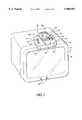
- FIG. 1is a perspective view of a videoconferencing unit, in accordance with the present invention, supported by a video display monitor;
- FIG. 2is a front elevational view of the videoconferencing unit, which clearly shows a base structure, a lip member, a tower assembly, venting grids, and a video camera unit;
- FIG. 3is a top plan view of the videoconferencing unit
- FIG. 4is a bottom plan view of the videoconferencing unit, illustrating a transmitter, a buffer member, and a lip gap formed in the lip member;
- FIG. 4Ais a bottom perspective view of a video display monitor with the videoconferencing unit's lip protruding in an outwardly direction;
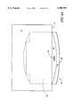
- FIG. 5is a side elevational view of the videoconferencing unit.
- FIGS. 1-5for a preferred embodiment of the invention, there is seen a videoconferencing unit, generally illustrated as 14, removably supported on a video display monitor 8.
- the video display monitor 8is a conventional monitor such as a television monitor or a computer monitor.
- the videoconferencing unit 14comprises a base structure 16 geometrically generally defined by a front portion 18, a rear portion 20, an upper surface 22, and a lower surface 24.
- the base structure 16rests on a top surface 10 of the video display monitor 8 such that the lower surface 24 is positioned proximal the top surface 10.
- a buffer member 26underlies the lower surface 24 to serve as a protective barrier against the video display monitor 8 (see FIG. 4).
- the primary function of buffer member 26is to prevent electromagnetic interference caused by the video display monitor 8.
- the buffer member 26is substantially coextensive with the base structure lower surface 24 and may be fabricated from a metallic or other suitable material. Venting grids 28 are dispersed throughout the upper surface to discharge the heat generated from the videoconferencing unit (see FIGS. 2 & 3).
- the videoconferencing unitadditionally comprises a lip member 30 formed integrally with or secured to the base structure 16.
- the lip member 30extends forwardly and downwardly from the front portion 18.
- a first group of microphones 32for the production of signals responsive to audio input, are set in the lip member 30 proximal the lowermost portion thereof.
- An inner wall 36 joined to an outer wall 34structurally define the lip member 30 (see FIGS. 4 & 4A).
- the inner wall 36is geometrically generally defined in an arch shape.
- the thickness of the width of the lip member 30decreases as it approaches the lip's middle portion 37, increasing in size as it expands outwards (see FIG. 4).
- a gap 38is formed in the lip member between the inner wall 36 of the lip 30 and the front surface 12 (see FIG. 4A).
- One or more transmitters 40which may comprise for example infrared light emitting diodes, are disposed within the gap 38.
- the transmittersare configured to transmit control signals to signal receivers 62 located on the video display monitor in order to effect control by the videoconferencing unit of various functional parameters of the video display monitor. For example, the transmitters may transmit a volume adjustment signal responsive to a user request.
- the gap 38permits the flow of ambient air therethrough to promote convective cooling of adjacent surfaces, thereby preventing overheating of the videoconferencing unit.
- the gap 38may further function to minimize physical obstruction of the transmitters which would interfere with the transmission of the control signal.
- the lip member 30engages in overhanging relation the upper front surface of the video display monitor 8.
- the lip memberthus serves to maintain the position of the videoconferencing unit with respect to the video display monitor and prevent its rearward displacement if, for example, cables or wires attached to ports located at the rear of the videoconferencing unit are inadvertently tugged.
- a tower member 42formed integrally with or secured to the base structure 16, extends upwardly from the rear portion 20.
- the tower member 42is adapted with venting grids 28 for facilitating the dissipation of heat generated by the operation of the videoconferencing unit 14.
- a second set of microphones 60are preferably set in the tower assembly 42 proximal to the upper edge surface thereof (see FIG. 3).
- differential signal analysismay be employed to identify the location of audio sources (i.e., videoconference participants). This technique may be used, for example, to enable camera tracking of a moving speaker or to focus on the participant who is speaking at any given time.
- Such differential signal analysis algorithmswhich generally involve comparing signals received from two or more spatially offset microphones, are known in the art and will not be discussed herein.
- a video camera 46of a type well known in the art, is housed within a pod unit 48, is connected to the upper surface 22.
- the pod unit 48is capable of rotating both in the vertical and horizontal plane of motion to enable adjustment of the camera's field of view.
- the base structure 16further houses electronic circuitry, of a type and description known in the art.
- the electronic circuitryis coupled to the microphones 32, the transmitters 40, the pod 48, and the video camera 46 to process the signals received therefrom and to communicate the processed signals to a remote videoconferencing unit.
- the base structure 16is preferably made of plastic or any other suitable polymer or material.
- the videoconferencing unit 14 of the present inventionprovides the desired communicating system without detracting from the overall aesthetics of the device.
Landscapes
- Engineering & Computer Science (AREA)
- Multimedia (AREA)
- Signal Processing (AREA)
- Studio Devices (AREA)
- Optical Communication System (AREA)
Abstract
Description
Claims (17)
Priority Applications (5)
| Application Number | Priority Date | Filing Date | Title |
|---|---|---|---|
| US08/953,276US5900907A (en) | 1997-10-17 | 1997-10-17 | Integrated videoconferencing unit |
| JP2000517548AJP2002532917A (en) | 1997-10-17 | 1998-07-29 | Integrated video conferencing device |
| PCT/US1998/015727WO1999021360A1 (en) | 1997-10-17 | 1998-07-29 | Integrated videoconferencing unit |
| EP98938091AEP1023805A4 (en) | 1997-10-17 | 1998-07-29 | INTEGRATED VIDEOCONFERENCE UNIT |
| CA002306107ACA2306107A1 (en) | 1997-10-17 | 1998-07-29 | Integrated videoconferencing unit |
Applications Claiming Priority (1)
| Application Number | Priority Date | Filing Date | Title |
|---|---|---|---|
| US08/953,276US5900907A (en) | 1997-10-17 | 1997-10-17 | Integrated videoconferencing unit |
Publications (1)
| Publication Number | Publication Date |
|---|---|
| US5900907Atrue US5900907A (en) | 1999-05-04 |
Family
ID=25493773
Family Applications (1)
| Application Number | Title | Priority Date | Filing Date |
|---|---|---|---|
| US08/953,276Expired - LifetimeUS5900907A (en) | 1997-10-17 | 1997-10-17 | Integrated videoconferencing unit |
Country Status (5)
| Country | Link |
|---|---|
| US (1) | US5900907A (en) |
| EP (1) | EP1023805A4 (en) |
| JP (1) | JP2002532917A (en) |
| CA (1) | CA2306107A1 (en) |
| WO (1) | WO1999021360A1 (en) |
Cited By (55)
| Publication number | Priority date | Publication date | Assignee | Title |
|---|---|---|---|---|
| US6137526A (en)* | 1995-02-16 | 2000-10-24 | Sumitomo Electric Industries, Ltd. | Two-way interactive system, terminal equipment and image pickup apparatus having mechanism for matching lines of sight between interlocutors through transmission means |
| WO2001031972A1 (en)* | 1999-10-22 | 2001-05-03 | Andrea Electronics Corporation | System and method for adaptive interference canceling |
| USD447758S1 (en) | 2001-01-19 | 2001-09-11 | Primax Electronics Ltd. | Camera |
| US6369847B1 (en) | 2000-03-17 | 2002-04-09 | Emtel, Inc. | Emergency facility video-conferencing system |
| US20020044682A1 (en)* | 2000-09-08 | 2002-04-18 | Weil Josef Oster | Method and apparatus for subject physical position and security determination |
| US6397275B1 (en) | 1994-09-07 | 2002-05-28 | Viseon, Inc. | Peripheral video conferencing system |
| USD458621S1 (en) | 2001-04-19 | 2002-06-11 | Canon Kabushiki Kaisha | Image input device |
| US6416239B1 (en)* | 2000-10-26 | 2002-07-09 | Chicony Electronics Co., Ltd. | Camera positioning seat |
| US6462781B1 (en)* | 1998-04-07 | 2002-10-08 | Pitcos Technologies, Inc. | Foldable teleconferencing camera |
| US20020149672A1 (en)* | 2001-04-13 | 2002-10-17 | Clapp Craig S.K. | Modular video conferencing system |
| USD467952S1 (en) | 2002-03-05 | 2002-12-31 | Sony Corporation | Video camera |
| USD470873S1 (en) | 2002-03-22 | 2003-02-25 | Polycom, Inc. | Videoconferencing system |
| USD471219S1 (en) | 2002-03-22 | 2003-03-04 | Polycom, Inc. | Videoconferencing system with extensible microphone arrays |
| USD471573S1 (en) | 2002-03-22 | 2003-03-11 | Polycom, Inc. | Videoconferencing system with extensible microphone arrays and microphone grills |
| USD471578S1 (en) | 2001-09-28 | 2003-03-11 | Intel Corporation | Digital camera stand |
| USD476345S1 (en) | 2002-09-09 | 2003-06-24 | Polycom, Inc. | Video camera |
| USD477622S1 (en) | 2002-09-06 | 2003-07-22 | Polycom, Inc. | Video camera system |
| US6618073B1 (en)* | 1998-11-06 | 2003-09-09 | Vtel Corporation | Apparatus and method for avoiding invalid camera positioning in a video conference |
| USD497925S1 (en) | 2002-12-11 | 2004-11-02 | Huawei Technologies Co., Ltd. | Video conferencing terminal |
| US20040257432A1 (en)* | 2003-06-20 | 2004-12-23 | Apple Computer, Inc. | Video conferencing system having focus control |
| US20040257431A1 (en)* | 2003-06-20 | 2004-12-23 | Apple Computer, Inc., A California Corporation | Video conferencing apparatus and method |
| USRE38884E1 (en)* | 1995-02-16 | 2005-11-22 | Sumitomo Electric Industries, Ltd. | Two-way interactive system, terminal equipment and image pickup apparatus having mechanism for matching lines of sight between interlocutors through transmission means |
| US7126816B2 (en) | 2004-03-12 | 2006-10-24 | Apple Computer, Inc. | Camera latch |
| US20060277254A1 (en)* | 2005-05-02 | 2006-12-07 | Kenoyer Michael L | Multi-component videoconferencing system |
| USD536719S1 (en)* | 2005-05-03 | 2007-02-13 | Lifesize Communications, Inc. | Camera |
| USD540358S1 (en)* | 2005-09-13 | 2007-04-10 | Chaim Sinai Orbach | Camera housing |
| USD545858S1 (en)* | 2005-08-12 | 2007-07-03 | Kye Systems Corp. | Web cam |
| USD546792S1 (en)* | 2005-01-24 | 2007-07-17 | Ginganet Corporation | Television telephone |
| US20070165106A1 (en)* | 2005-05-02 | 2007-07-19 | Groves Randall D | Distributed Videoconferencing Processing |
| USD562868S1 (en)* | 2006-08-31 | 2008-02-26 | Canon Kabushiki Kaisha | Network camera |
| USD566148S1 (en)* | 2006-03-16 | 2008-04-08 | Sony Corporation | Video camera |
| US20080088696A1 (en)* | 2005-06-03 | 2008-04-17 | Hernan Giraldo | Compact, portable universal script prompter and videoconferencing eye contact-assisting device for personal computers |
| US20080095401A1 (en)* | 2006-10-19 | 2008-04-24 | Polycom, Inc. | Ultrasonic camera tracking system and associated methods |
| US20080316297A1 (en)* | 2007-06-22 | 2008-12-25 | King Keith C | Video Conferencing Device which Performs Multi-way Conferencing |
| USD589996S1 (en) | 2008-02-07 | 2009-04-07 | Lifesize Communications, Inc. | Flat mounted camera |
| USD589995S1 (en) | 2008-02-07 | 2009-04-07 | Lifesize Communications, Inc. | Mountable camera |
| USD590000S1 (en) | 2008-02-07 | 2009-04-07 | Lifesize Communications, Inc. | Camera stand |
| US20090115838A1 (en)* | 2001-08-07 | 2009-05-07 | Polycom, Inc. | System and method for high resolution videoconferencing |
| US20090153804A1 (en)* | 2004-06-07 | 2009-06-18 | Hernan Giraldo | Apparatus, system, and method for the desktop-based creation, management, and publication of enhanced audiovisual presentations |
| US20100225737A1 (en)* | 2009-03-04 | 2010-09-09 | King Keith C | Videoconferencing Endpoint Extension |
| US20100225736A1 (en)* | 2009-03-04 | 2010-09-09 | King Keith C | Virtual Distributed Multipoint Control Unit |
| US20110115876A1 (en)* | 2009-11-16 | 2011-05-19 | Gautam Khot | Determining a Videoconference Layout Based on Numbers of Participants |
| US8139100B2 (en) | 2007-07-13 | 2012-03-20 | Lifesize Communications, Inc. | Virtual multiway scaler compensation |
| JP2012147420A (en)* | 2010-12-22 | 2012-08-02 | Ricoh Co Ltd | Image processing device and image processing system |
| US20130169740A1 (en)* | 2011-12-28 | 2013-07-04 | Samsung Electronics Co., Ltd. | Display apparatus |
| US20140063734A1 (en)* | 2012-08-30 | 2014-03-06 | Draeger Safety Uk Limited | Mounting assembly |
| CN105263083A (en)* | 2014-07-18 | 2016-01-20 | 纬创资通股份有限公司 | Loudspeaker module, display device, adjusting system, control method and simulcasting method |
| US9389643B1 (en) | 1998-09-18 | 2016-07-12 | Intermetro Industries Corporation | Mobile computer workstation |
| US20160282900A1 (en)* | 2015-03-24 | 2016-09-29 | T1V, Inc. | Frame having components integrated therein |
| USD788725S1 (en) | 2015-09-11 | 2017-06-06 | Polycom, Inc. | Videoconferencing unit |
| US10619787B1 (en)* | 2018-08-29 | 2020-04-14 | Facebook, Inc. | Mounting systems for a video-conferencing device, video conferencing systems, and related methods |
| USD905780S1 (en) | 2019-01-24 | 2020-12-22 | Polycom, Inc. | Videoconferencing camera |
| USD907595S1 (en) | 2018-11-26 | 2021-01-12 | Polycom, Inc. | Videoconferencing unit |
| US20210357008A1 (en)* | 2020-05-18 | 2021-11-18 | Beijing Xiaomi Mobile Software Co., Ltd. | Integrated module and display equipment |
| US20230305604A1 (en)* | 2022-03-22 | 2023-09-28 | Dell Products L.P. | Information handling system display peripheral with a detachable integrated camera |
Citations (6)
| Publication number | Priority date | Publication date | Assignee | Title |
|---|---|---|---|---|
| US5438357A (en)* | 1993-11-23 | 1995-08-01 | Mcnelley; Steve H. | Image manipulating teleconferencing system |
| US5539451A (en)* | 1994-12-27 | 1996-07-23 | At&T Corp. | Method and apparatus for channel spinning off a channel |
| US5612733A (en)* | 1994-07-18 | 1997-03-18 | C-Phone Corporation | Optics orienting arrangement for videoconferencing system |
| US5734414A (en)* | 1994-03-03 | 1998-03-31 | Matsushita Electric Industrial Co., Ltd. | Camera apparatus for electronic conference |
| US5760824A (en)* | 1995-12-29 | 1998-06-02 | Lucent Technologies Inc. | Multimedia telephone having wireless camera and television module and method of operation thereof |
| US5778082A (en)* | 1996-06-14 | 1998-07-07 | Picturetel Corporation | Method and apparatus for localization of an acoustic source |
Family Cites Families (1)
| Publication number | Priority date | Publication date | Assignee | Title |
|---|---|---|---|---|
| US4802227A (en)* | 1987-04-03 | 1989-01-31 | American Telephone And Telegraph Company | Noise reduction processing arrangement for microphone arrays |
- 1997
- 1997-10-17USUS08/953,276patent/US5900907A/ennot_activeExpired - Lifetime
- 1998
- 1998-07-29EPEP98938091Apatent/EP1023805A4/ennot_activeWithdrawn
- 1998-07-29JPJP2000517548Apatent/JP2002532917A/enactivePending
- 1998-07-29CACA002306107Apatent/CA2306107A1/ennot_activeAbandoned
- 1998-07-29WOPCT/US1998/015727patent/WO1999021360A1/enactiveSearch and Examination
Patent Citations (6)
| Publication number | Priority date | Publication date | Assignee | Title |
|---|---|---|---|---|
| US5438357A (en)* | 1993-11-23 | 1995-08-01 | Mcnelley; Steve H. | Image manipulating teleconferencing system |
| US5734414A (en)* | 1994-03-03 | 1998-03-31 | Matsushita Electric Industrial Co., Ltd. | Camera apparatus for electronic conference |
| US5612733A (en)* | 1994-07-18 | 1997-03-18 | C-Phone Corporation | Optics orienting arrangement for videoconferencing system |
| US5539451A (en)* | 1994-12-27 | 1996-07-23 | At&T Corp. | Method and apparatus for channel spinning off a channel |
| US5760824A (en)* | 1995-12-29 | 1998-06-02 | Lucent Technologies Inc. | Multimedia telephone having wireless camera and television module and method of operation thereof |
| US5778082A (en)* | 1996-06-14 | 1998-07-07 | Picturetel Corporation | Method and apparatus for localization of an acoustic source |
Cited By (90)
| Publication number | Priority date | Publication date | Assignee | Title |
|---|---|---|---|---|
| US6654825B2 (en) | 1994-09-07 | 2003-11-25 | Rsi Systems, Inc. | Peripheral video conferencing system with control unit for adjusting the transmission bandwidth of the communication channel |
| US6397275B1 (en) | 1994-09-07 | 2002-05-28 | Viseon, Inc. | Peripheral video conferencing system |
| US6519662B2 (en) | 1994-09-07 | 2003-02-11 | Rsi Systems, Inc. | Peripheral video conferencing system |
| USRE38884E1 (en)* | 1995-02-16 | 2005-11-22 | Sumitomo Electric Industries, Ltd. | Two-way interactive system, terminal equipment and image pickup apparatus having mechanism for matching lines of sight between interlocutors through transmission means |
| US6137526A (en)* | 1995-02-16 | 2000-10-24 | Sumitomo Electric Industries, Ltd. | Two-way interactive system, terminal equipment and image pickup apparatus having mechanism for matching lines of sight between interlocutors through transmission means |
| US6462781B1 (en)* | 1998-04-07 | 2002-10-08 | Pitcos Technologies, Inc. | Foldable teleconferencing camera |
| US9389643B1 (en) | 1998-09-18 | 2016-07-12 | Intermetro Industries Corporation | Mobile computer workstation |
| US6618073B1 (en)* | 1998-11-06 | 2003-09-09 | Vtel Corporation | Apparatus and method for avoiding invalid camera positioning in a video conference |
| WO2001031972A1 (en)* | 1999-10-22 | 2001-05-03 | Andrea Electronics Corporation | System and method for adaptive interference canceling |
| US6369847B1 (en) | 2000-03-17 | 2002-04-09 | Emtel, Inc. | Emergency facility video-conferencing system |
| USRE42288E1 (en) | 2000-03-17 | 2011-04-12 | Emtel, Inc. | Emergency facility video-conferencing system |
| US7106885B2 (en)* | 2000-09-08 | 2006-09-12 | Carecord Technologies, Inc. | Method and apparatus for subject physical position and security determination |
| US20020044682A1 (en)* | 2000-09-08 | 2002-04-18 | Weil Josef Oster | Method and apparatus for subject physical position and security determination |
| US6416239B1 (en)* | 2000-10-26 | 2002-07-09 | Chicony Electronics Co., Ltd. | Camera positioning seat |
| USD447758S1 (en) | 2001-01-19 | 2001-09-11 | Primax Electronics Ltd. | Camera |
| US20020149672A1 (en)* | 2001-04-13 | 2002-10-17 | Clapp Craig S.K. | Modular video conferencing system |
| EP1380165A4 (en)* | 2001-04-13 | 2006-04-26 | Polycom Inc | MODULAR VIDEO CONFERENCE SYSTEM |
| USD458621S1 (en) | 2001-04-19 | 2002-06-11 | Canon Kabushiki Kaisha | Image input device |
| US8077194B2 (en)* | 2001-08-07 | 2011-12-13 | Polycom, Inc. | System and method for high resolution videoconferencing |
| US20090115838A1 (en)* | 2001-08-07 | 2009-05-07 | Polycom, Inc. | System and method for high resolution videoconferencing |
| USD471578S1 (en) | 2001-09-28 | 2003-03-11 | Intel Corporation | Digital camera stand |
| USD467952S1 (en) | 2002-03-05 | 2002-12-31 | Sony Corporation | Video camera |
| USD471573S1 (en) | 2002-03-22 | 2003-03-11 | Polycom, Inc. | Videoconferencing system with extensible microphone arrays and microphone grills |
| USD471219S1 (en) | 2002-03-22 | 2003-03-04 | Polycom, Inc. | Videoconferencing system with extensible microphone arrays |
| USD470873S1 (en) | 2002-03-22 | 2003-02-25 | Polycom, Inc. | Videoconferencing system |
| USD477622S1 (en) | 2002-09-06 | 2003-07-22 | Polycom, Inc. | Video camera system |
| USD476345S1 (en) | 2002-09-09 | 2003-06-24 | Polycom, Inc. | Video camera |
| USD497925S1 (en) | 2002-12-11 | 2004-11-02 | Huawei Technologies Co., Ltd. | Video conferencing terminal |
| US20080218583A1 (en)* | 2003-06-20 | 2008-09-11 | Apple Inc. | Video conferencing apparatus and method |
| US7397495B2 (en) | 2003-06-20 | 2008-07-08 | Apple Inc. | Video conferencing apparatus and method |
| US20040257432A1 (en)* | 2003-06-20 | 2004-12-23 | Apple Computer, Inc. | Video conferencing system having focus control |
| US7559026B2 (en) | 2003-06-20 | 2009-07-07 | Apple Inc. | Video conferencing system having focus control |
| US20040257431A1 (en)* | 2003-06-20 | 2004-12-23 | Apple Computer, Inc., A California Corporation | Video conferencing apparatus and method |
| US8179419B2 (en) | 2003-06-20 | 2012-05-15 | Apple Inc. | Video conferencing apparatus and method |
| US8384518B2 (en) | 2004-03-12 | 2013-02-26 | Apple Inc. | Illuminable latch |
| US20060268505A1 (en)* | 2004-03-12 | 2006-11-30 | Apple Computer, Inc. | Camera latch |
| US7126816B2 (en) | 2004-03-12 | 2006-10-24 | Apple Computer, Inc. | Camera latch |
| US7570485B2 (en)* | 2004-03-12 | 2009-08-04 | Apple Inc. | Camera latch |
| US20090268401A1 (en)* | 2004-03-12 | 2009-10-29 | Apple Inc. | Camera latch |
| US8035481B2 (en) | 2004-03-12 | 2011-10-11 | Apple Inc. | Illuminable latch |
| US7972006B2 (en)* | 2004-06-07 | 2011-07-05 | Promptvideo Corporation | Apparatus, system, and method for the desktop-based creation, management, and publication of enhanced audiovisual presentations |
| US20090153804A1 (en)* | 2004-06-07 | 2009-06-18 | Hernan Giraldo | Apparatus, system, and method for the desktop-based creation, management, and publication of enhanced audiovisual presentations |
| USD546792S1 (en)* | 2005-01-24 | 2007-07-17 | Ginganet Corporation | Television telephone |
| US20060277254A1 (en)* | 2005-05-02 | 2006-12-07 | Kenoyer Michael L | Multi-component videoconferencing system |
| US20070009114A1 (en)* | 2005-05-02 | 2007-01-11 | Kenoyer Michael L | Integrated videoconferencing system |
| US7986335B2 (en) | 2005-05-02 | 2011-07-26 | Lifesize Communications, Inc. | Set top box videoconferencing system |
| US7907164B2 (en) | 2005-05-02 | 2011-03-15 | Lifesize Communications, Inc. | Integrated videoconferencing system |
| US20070009113A1 (en)* | 2005-05-02 | 2007-01-11 | Kenoyer Michael L | Set top box videoconferencing system |
| US20070165106A1 (en)* | 2005-05-02 | 2007-07-19 | Groves Randall D | Distributed Videoconferencing Processing |
| USD536719S1 (en)* | 2005-05-03 | 2007-02-13 | Lifesize Communications, Inc. | Camera |
| US20080088696A1 (en)* | 2005-06-03 | 2008-04-17 | Hernan Giraldo | Compact, portable universal script prompter and videoconferencing eye contact-assisting device for personal computers |
| USD545858S1 (en)* | 2005-08-12 | 2007-07-03 | Kye Systems Corp. | Web cam |
| USD540358S1 (en)* | 2005-09-13 | 2007-04-10 | Chaim Sinai Orbach | Camera housing |
| USD566148S1 (en)* | 2006-03-16 | 2008-04-08 | Sony Corporation | Video camera |
| USD562868S1 (en)* | 2006-08-31 | 2008-02-26 | Canon Kabushiki Kaisha | Network camera |
| US8249298B2 (en) | 2006-10-19 | 2012-08-21 | Polycom, Inc. | Ultrasonic camera tracking system and associated methods |
| US20080095401A1 (en)* | 2006-10-19 | 2008-04-24 | Polycom, Inc. | Ultrasonic camera tracking system and associated methods |
| US20080316295A1 (en)* | 2007-06-22 | 2008-12-25 | King Keith C | Virtual decoders |
| US20080316298A1 (en)* | 2007-06-22 | 2008-12-25 | King Keith C | Video Decoder which Processes Multiple Video Streams |
| US20080316297A1 (en)* | 2007-06-22 | 2008-12-25 | King Keith C | Video Conferencing Device which Performs Multi-way Conferencing |
| US8633962B2 (en) | 2007-06-22 | 2014-01-21 | Lifesize Communications, Inc. | Video decoder which processes multiple video streams |
| US8581959B2 (en) | 2007-06-22 | 2013-11-12 | Lifesize Communications, Inc. | Video conferencing system which allows endpoints to perform continuous presence layout selection |
| US8237765B2 (en) | 2007-06-22 | 2012-08-07 | Lifesize Communications, Inc. | Video conferencing device which performs multi-way conferencing |
| US8319814B2 (en) | 2007-06-22 | 2012-11-27 | Lifesize Communications, Inc. | Video conferencing system which allows endpoints to perform continuous presence layout selection |
| US8139100B2 (en) | 2007-07-13 | 2012-03-20 | Lifesize Communications, Inc. | Virtual multiway scaler compensation |
| USD590000S1 (en) | 2008-02-07 | 2009-04-07 | Lifesize Communications, Inc. | Camera stand |
| USD589995S1 (en) | 2008-02-07 | 2009-04-07 | Lifesize Communications, Inc. | Mountable camera |
| USD589996S1 (en) | 2008-02-07 | 2009-04-07 | Lifesize Communications, Inc. | Flat mounted camera |
| US8643695B2 (en) | 2009-03-04 | 2014-02-04 | Lifesize Communications, Inc. | Videoconferencing endpoint extension |
| US20100225737A1 (en)* | 2009-03-04 | 2010-09-09 | King Keith C | Videoconferencing Endpoint Extension |
| US8456510B2 (en) | 2009-03-04 | 2013-06-04 | Lifesize Communications, Inc. | Virtual distributed multipoint control unit |
| US20100225736A1 (en)* | 2009-03-04 | 2010-09-09 | King Keith C | Virtual Distributed Multipoint Control Unit |
| US20110115876A1 (en)* | 2009-11-16 | 2011-05-19 | Gautam Khot | Determining a Videoconference Layout Based on Numbers of Participants |
| US8350891B2 (en) | 2009-11-16 | 2013-01-08 | Lifesize Communications, Inc. | Determining a videoconference layout based on numbers of participants |
| JP2012147420A (en)* | 2010-12-22 | 2012-08-02 | Ricoh Co Ltd | Image processing device and image processing system |
| US20130169740A1 (en)* | 2011-12-28 | 2013-07-04 | Samsung Electronics Co., Ltd. | Display apparatus |
| US20140063734A1 (en)* | 2012-08-30 | 2014-03-06 | Draeger Safety Uk Limited | Mounting assembly |
| US9256254B2 (en)* | 2012-08-30 | 2016-02-09 | Draeger Safety Uk Limited | Mounting assembly |
| US10165378B2 (en)* | 2014-07-18 | 2018-12-25 | Wistron Corp. | Speaker module, display device having a speaker module, audio adjustment system and control method thereof, and synchronization method for playing multi-language sound |
| CN105263083A (en)* | 2014-07-18 | 2016-01-20 | 纬创资通股份有限公司 | Loudspeaker module, display device, adjusting system, control method and simulcasting method |
| US20160021454A1 (en)* | 2014-07-18 | 2016-01-21 | Wistron Corp. | Speaker module, display device having a speaker module, audio adjustment system and control method thereof, and synchronization method for playing multi-language sound |
| US20160282900A1 (en)* | 2015-03-24 | 2016-09-29 | T1V, Inc. | Frame having components integrated therein |
| USD788725S1 (en) | 2015-09-11 | 2017-06-06 | Polycom, Inc. | Videoconferencing unit |
| US10619787B1 (en)* | 2018-08-29 | 2020-04-14 | Facebook, Inc. | Mounting systems for a video-conferencing device, video conferencing systems, and related methods |
| USD907595S1 (en) | 2018-11-26 | 2021-01-12 | Polycom, Inc. | Videoconferencing unit |
| USD905780S1 (en) | 2019-01-24 | 2020-12-22 | Polycom, Inc. | Videoconferencing camera |
| USD1056012S1 (en) | 2019-01-24 | 2024-12-31 | Hewlett-Packard Development Company, L.P. | Videoconferencing camera |
| US20210357008A1 (en)* | 2020-05-18 | 2021-11-18 | Beijing Xiaomi Mobile Software Co., Ltd. | Integrated module and display equipment |
| US20230305604A1 (en)* | 2022-03-22 | 2023-09-28 | Dell Products L.P. | Information handling system display peripheral with a detachable integrated camera |
| US11829208B2 (en)* | 2022-03-22 | 2023-11-28 | Dell Products L.P. | Information handling system display peripheral with a detachable integrated camera |
Also Published As
| Publication number | Publication date |
|---|---|
| WO1999021360A1 (en) | 1999-04-29 |
| EP1023805A1 (en) | 2000-08-02 |
| CA2306107A1 (en) | 1999-04-29 |
| JP2002532917A (en) | 2002-10-02 |
| EP1023805A4 (en) | 2000-10-11 |
Similar Documents
| Publication | Publication Date | Title |
|---|---|---|
| US5900907A (en) | Integrated videoconferencing unit | |
| US11290681B2 (en) | System and methods for facilitating virtual presence | |
| US5612733A (en) | Optics orienting arrangement for videoconferencing system | |
| KR100960781B1 (en) | Integrated design for omnidirectional camera and microphone array | |
| CA1276673C (en) | Conference table | |
| US8063929B2 (en) | Managing scene transitions for video communication | |
| Cutler et al. | Distributed meetings: A meeting capture and broadcasting system | |
| US8154583B2 (en) | Eye gazing imaging for video communications | |
| US7576766B2 (en) | Normalized images for cameras | |
| US8253770B2 (en) | Residential video communication system | |
| US8284230B2 (en) | Video communication device and camera tracking method thereof | |
| JP3115798B2 (en) | Audio tracking video system | |
| US8154578B2 (en) | Multi-camera residential communication system | |
| US20020140804A1 (en) | Method and apparatus for audio/image speaker detection and locator | |
| US20050007445A1 (en) | Telepresence system and method for video teleconferencing | |
| US20030160862A1 (en) | Apparatus having cooperating wide-angle digital camera system and microphone array | |
| US7271827B2 (en) | System and method for recording moving images | |
| WO2008075726A1 (en) | Video conferencing device | |
| US5436654A (en) | Lens tilt mechanism for video teleconferencing unit | |
| WO2020003695A1 (en) | Information processing device, information processing method, and information processing system | |
| US12135494B2 (en) | Universal mount for a camera | |
| US20020078274A1 (en) | Electronic apparatus having hub function | |
| JP2006074388A (en) | Imaging apparatus, bidirectional interactive system including the same, and AV data correction method |
Legal Events
| Date | Code | Title | Description |
|---|---|---|---|
| AS | Assignment | Owner name:POLYCOM, INC., CALIFORNIA Free format text:ASSIGNMENT OF ASSIGNORS INTEREST;ASSIGNORS:MALLOY, CRAIG;KENOYER, MICHAEL;VANDERWILT, PAT;REEL/FRAME:009113/0731 Effective date:19980402 Owner name:POLYCOM, INC., CALIFORNIA Free format text:ASSIGNMENT OF ASSIGNORS INTEREST;ASSIGNOR:WAKEFIELD, SCOTT;REEL/FRAME:009099/0327 Effective date:19980325 | |
| STCF | Information on status: patent grant | Free format text:PATENTED CASE | |
| FEPP | Fee payment procedure | Free format text:PAT HOLDER NO LONGER CLAIMS SMALL ENTITY STATUS, ENTITY STATUS SET TO UNDISCOUNTED (ORIGINAL EVENT CODE: STOL); ENTITY STATUS OF PATENT OWNER: LARGE ENTITY | |
| REFU | Refund | Free format text:REFUND - SURCHARGE, PETITION TO ACCEPT PYMT AFTER EXP, UNINTENTIONAL (ORIGINAL EVENT CODE: R2551); ENTITY STATUS OF PATENT OWNER: LARGE ENTITY | |
| FPAY | Fee payment | Year of fee payment:4 | |
| FEPP | Fee payment procedure | Free format text:PAYOR NUMBER ASSIGNED (ORIGINAL EVENT CODE: ASPN); ENTITY STATUS OF PATENT OWNER: LARGE ENTITY | |
| FPAY | Fee payment | Year of fee payment:8 | |
| FPAY | Fee payment | Year of fee payment:12 | |
| AS | Assignment | Owner name:MORGAN STANLEY SENIOR FUNDING, INC., NEW YORK Free format text:SECURITY AGREEMENT;ASSIGNORS:POLYCOM, INC.;VIVU, INC.;REEL/FRAME:031785/0592 Effective date:20130913 | |
| AS | Assignment | Owner name:MACQUARIE CAPITAL FUNDING LLC, AS COLLATERAL AGENT, NEW YORK Free format text:GRANT OF SECURITY INTEREST IN PATENTS - FIRST LIEN;ASSIGNOR:POLYCOM, INC.;REEL/FRAME:040168/0094 Effective date:20160927 Owner name:MACQUARIE CAPITAL FUNDING LLC, AS COLLATERAL AGENT, NEW YORK Free format text:GRANT OF SECURITY INTEREST IN PATENTS - SECOND LIEN;ASSIGNOR:POLYCOM, INC.;REEL/FRAME:040168/0459 Effective date:20160927 Owner name:VIVU, INC., CALIFORNIA Free format text:RELEASE BY SECURED PARTY;ASSIGNOR:MORGAN STANLEY SENIOR FUNDING, INC.;REEL/FRAME:040166/0162 Effective date:20160927 Owner name:POLYCOM, INC., CALIFORNIA Free format text:RELEASE BY SECURED PARTY;ASSIGNOR:MORGAN STANLEY SENIOR FUNDING, INC.;REEL/FRAME:040166/0162 Effective date:20160927 Owner name:MACQUARIE CAPITAL FUNDING LLC, AS COLLATERAL AGENT Free format text:GRANT OF SECURITY INTEREST IN PATENTS - FIRST LIEN;ASSIGNOR:POLYCOM, INC.;REEL/FRAME:040168/0094 Effective date:20160927 Owner name:MACQUARIE CAPITAL FUNDING LLC, AS COLLATERAL AGENT Free format text:GRANT OF SECURITY INTEREST IN PATENTS - SECOND LIEN;ASSIGNOR:POLYCOM, INC.;REEL/FRAME:040168/0459 Effective date:20160927 | |
| AS | Assignment | Owner name:POLYCOM, INC., COLORADO Free format text:RELEASE BY SECURED PARTY;ASSIGNOR:MACQUARIE CAPITAL FUNDING LLC;REEL/FRAME:046472/0815 Effective date:20180702 Owner name:POLYCOM, INC., COLORADO Free format text:RELEASE BY SECURED PARTY;ASSIGNOR:MACQUARIE CAPITAL FUNDING LLC;REEL/FRAME:047247/0615 Effective date:20180702 |