US5900895A - Method for refilling an ink supply for an ink-jet printer - Google Patents
Method for refilling an ink supply for an ink-jet printerDownload PDFInfo
- Publication number
- US5900895A US5900895AUS08/566,642US56664295AUS5900895AUS 5900895 AUS5900895 AUS 5900895AUS 56664295 AUS56664295 AUS 56664295AUS 5900895 AUS5900895 AUS 5900895A
- Authority
- US
- United States
- Prior art keywords
- ink
- reservoir
- chamber
- valve
- supply
- Prior art date
- Legal status (The legal status is an assumption and is not a legal conclusion. Google has not performed a legal analysis and makes no representation as to the accuracy of the status listed.)
- Expired - Lifetime
Links
- 238000000034methodMethods0.000titleclaimsdescription23
- 239000012530fluidSubstances0.000claimsdescription65
- 239000000463materialSubstances0.000claimsdescription13
- 230000009977dual effectEffects0.000claims1
- 239000000976inkSubstances0.000description239
- 238000003032molecular dockingMethods0.000description21
- 238000007789sealingMethods0.000description16
- 230000006835compressionEffects0.000description7
- 238000007906compressionMethods0.000description7
- 230000007246mechanismEffects0.000description7
- 239000002985plastic filmSubstances0.000description7
- CURLTUGMZLYLDI-UHFFFAOYSA-NCarbon dioxideChemical compoundO=C=OCURLTUGMZLYLDI-UHFFFAOYSA-N0.000description6
- 238000003780insertionMethods0.000description6
- 230000037431insertionEffects0.000description6
- 229920001684low density polyethylenePolymers0.000description6
- 239000004702low-density polyethyleneSubstances0.000description6
- XLYOFNOQVPJJNP-UHFFFAOYSA-NwaterSubstancesOXLYOFNOQVPJJNP-UHFFFAOYSA-N0.000description5
- 229920000134Metallised filmPolymers0.000description4
- 230000003247decreasing effectEffects0.000description4
- -1polypropylenePolymers0.000description4
- 238000007639printingMethods0.000description4
- 230000001105regulatory effectEffects0.000description4
- 239000004743PolypropyleneSubstances0.000description3
- 239000000853adhesiveSubstances0.000description3
- 230000001070adhesive effectEffects0.000description3
- 229910002092carbon dioxideInorganic materials0.000description3
- 239000001569carbon dioxideSubstances0.000description3
- 230000036961partial effectEffects0.000description3
- 229920001155polypropylenePolymers0.000description3
- 230000008569processEffects0.000description3
- 230000001681protective effectEffects0.000description3
- 229910001220stainless steelInorganic materials0.000description3
- 239000010935stainless steelSubstances0.000description3
- 230000004888barrier functionEffects0.000description2
- 238000004891communicationMethods0.000description2
- 230000008878couplingEffects0.000description2
- 238000010168coupling processMethods0.000description2
- 238000005859coupling reactionMethods0.000description2
- 238000005429filling processMethods0.000description2
- 230000005484gravityEffects0.000description2
- 229920003023plasticPolymers0.000description2
- 239000004033plasticSubstances0.000description2
- 239000005020polyethylene terephthalateSubstances0.000description2
- 229920000139polyethylene terephthalatePolymers0.000description2
- 230000000717retained effectEffects0.000description2
- 230000003068static effectEffects0.000description2
- 239000004820Pressure-sensitive adhesiveSubstances0.000description1
- 238000007792additionMethods0.000description1
- 230000002411adverseEffects0.000description1
- XAGFODPZIPBFFR-UHFFFAOYSA-NaluminiumChemical compound[Al]XAGFODPZIPBFFR-UHFFFAOYSA-N0.000description1
- 229910052782aluminiumInorganic materials0.000description1
- 239000003086colorantSubstances0.000description1
- 239000000356contaminantSubstances0.000description1
- 238000007796conventional methodMethods0.000description1
- 230000007423decreaseEffects0.000description1
- 238000006073displacement reactionMethods0.000description1
- 229920001971elastomerPolymers0.000description1
- HQQADJVZYDDRJT-UHFFFAOYSA-Nethene;prop-1-eneChemical groupC=C.CC=CHQQADJVZYDDRJT-UHFFFAOYSA-N0.000description1
- 229920002457flexible plasticPolymers0.000description1
- 229920001903high density polyethylenePolymers0.000description1
- 239000004700high-density polyethyleneSubstances0.000description1
- 238000011900installation processMethods0.000description1
- 238000005304joiningMethods0.000description1
- 238000004519manufacturing processMethods0.000description1
- 238000012986modificationMethods0.000description1
- 230000004048modificationEffects0.000description1
- 239000000178monomerSubstances0.000description1
- 239000002245particleSubstances0.000description1
- 229920001195polyisoprenePolymers0.000description1
- 238000003825pressingMethods0.000description1
- 230000002829reductive effectEffects0.000description1
- 238000000926separation methodMethods0.000description1
- 230000000087stabilizing effectEffects0.000description1
- 239000000126substanceSubstances0.000description1
- 238000006467substitution reactionMethods0.000description1
- 238000003466weldingMethods0.000description1
- 230000037303wrinklesEffects0.000description1
Images


Classifications
- B—PERFORMING OPERATIONS; TRANSPORTING
- B41—PRINTING; LINING MACHINES; TYPEWRITERS; STAMPS
- B41J—TYPEWRITERS; SELECTIVE PRINTING MECHANISMS, i.e. MECHANISMS PRINTING OTHERWISE THAN FROM A FORME; CORRECTION OF TYPOGRAPHICAL ERRORS
- B41J2/00—Typewriters or selective printing mechanisms characterised by the printing or marking process for which they are designed
- B41J2/005—Typewriters or selective printing mechanisms characterised by the printing or marking process for which they are designed characterised by bringing liquid or particles selectively into contact with a printing material
- B41J2/01—Ink jet
- B41J2/17—Ink jet characterised by ink handling
- B41J2/175—Ink supply systems ; Circuit parts therefor
- B41J2/17503—Ink cartridges
- B41J2/1752—Mounting within the printer
- B—PERFORMING OPERATIONS; TRANSPORTING
- B41—PRINTING; LINING MACHINES; TYPEWRITERS; STAMPS
- B41J—TYPEWRITERS; SELECTIVE PRINTING MECHANISMS, i.e. MECHANISMS PRINTING OTHERWISE THAN FROM A FORME; CORRECTION OF TYPOGRAPHICAL ERRORS
- B41J2/00—Typewriters or selective printing mechanisms characterised by the printing or marking process for which they are designed
- B41J2/005—Typewriters or selective printing mechanisms characterised by the printing or marking process for which they are designed characterised by bringing liquid or particles selectively into contact with a printing material
- B41J2/01—Ink jet
- B41J2/17—Ink jet characterised by ink handling
- B41J2/175—Ink supply systems ; Circuit parts therefor
- B41J2/17503—Ink cartridges
- B41J2/17506—Refilling of the cartridge
- B—PERFORMING OPERATIONS; TRANSPORTING
- B41—PRINTING; LINING MACHINES; TYPEWRITERS; STAMPS
- B41J—TYPEWRITERS; SELECTIVE PRINTING MECHANISMS, i.e. MECHANISMS PRINTING OTHERWISE THAN FROM A FORME; CORRECTION OF TYPOGRAPHICAL ERRORS
- B41J2/00—Typewriters or selective printing mechanisms characterised by the printing or marking process for which they are designed
- B41J2/005—Typewriters or selective printing mechanisms characterised by the printing or marking process for which they are designed characterised by bringing liquid or particles selectively into contact with a printing material
- B41J2/01—Ink jet
- B41J2/17—Ink jet characterised by ink handling
- B41J2/175—Ink supply systems ; Circuit parts therefor
- B41J2/17503—Ink cartridges
- B41J2/17513—Inner structure
Definitions
- the present inventionrelates to a method for refilling a reusable ink supply having a pressurized chamber.
- a typical ink-jet printerhas a pen mounted to a carriage that traverses a printing surface, such as a piece of paper.
- the pencarries a print head.
- a control systemactivates ink-jets on the print head to eject, or jet, ink drops onto the printing surface and form desired images and characters.
- ink-jet printersuse a disposable ink pen that can be mounted to the carriage.
- Such an ink pentypically includes, in addition to the print head, a reservoir containing a supply of ink.
- the ink penalso typically includes pressure regulating mechanisms to maintain the ink supply at an appropriate pressure for use by the print head. When the ink supply is exhausted, the ink pen is disposed of and a new ink pen is installed. This system provides an easy, user friendly way of providing an ink supply for an ink-jet printer.
- the entire ink penincluding the reservoir and ink supply, is moved with the print head. This requires a trade-off. If the ink pen has a large reservoir and ink supply, it is heavier and is more difficult to move quickly. This may limit the speed with which the printer can print--an important characteristic of a printer. On the other hand, if the ink pen has a small reservoir and ink supply, it will be depleted more quickly and require more frequent replacement.
- the ink penmay no longer be able to print as intended.
- the ink penmust typically be replaced and discarded, or at least removed for refilling, when the first of the reservoirs is exhausted. This further decreases the useful life of the ink pen.
- the print head and pressure regulating mechanism of the ink pencontribute substantially to the cost of the ink pen. These mechanisms can also have a useful life expectancy far longer than the supply of ink in the reservoir. Thus, when the ink pen is discarded, the print head and pressure regulating mechanisms may have a great deal of usable life remaining. In addition, in multiple color ink pens, it is unlikely that all of the ink reservoirs will be depleted at the same time. Thus, the discarded ink pen will likely contain unused ink as well as a fully functional print head and pressure regulating mechanism. This results in increased cost to the user and a somewhat wasteful and inefficient use of resources.
- ink-jet printershave used ink supplies that are not mounted to the carriage. Such ink supplies, because they are stationary within the printer, are not subject to all of the size limitations of an ink supply that is moved with the carriage.
- Some printers with stationary ink supplieshave a refillable ink reservoir built into the printer. Ink is supplied from the reservoir to the print head through a tube which trails from the print head.
- the print headcan include a small ink reservoir that is periodically replenished by moving the print head to a filling station at the stationary, built-in reservoir.
- inkmay be supplied from the reservoir to the print head by either a pump within the printer or by gravity flow.
- replaceable reservoirsIn view of these problems, some printers use replaceable reservoirs. These reservoirs, like the built-in reservoirs are not located on the carriage and, thus, are not moved with the print head during printing. Replaceable reservoirs sometimes are plastic bags filled with ink.
- the bagis provided with a mechanism, such as a septum which can be punctured by a hollow needle, for coupling it to the printer so that ink may flow from the bag to the print head.
- the bagis squeezed, or pressurized in some other manner, to cause the ink to flow from the reservoir. Should the bag burst or leak while under pressure, the consequences can be catastrophic for the printer.
- One particular replaceable reservoirreliably supplies ink to the print head, yet is not complicated and can be manufactured simply and inexpensively. This reservoir is also easily recyclable.
- the replaceable reservoirhas an ink supply that has a main reservoir for holding a supply of ink.
- the main reservoirwhich is typically maintained at about ambient pressure, is coupled to a variable volume chamber via a valve that allows the flow of ink from the reservoir to the chamber and limits the flow of ink from the chamber to the reservoir.
- the chamberis coupled to a fluid outlet which is normally closed to prevent the flow of ink. However, when the ink supply is installed in a printer, the fluid outlet opens to establish a fluid connection between the chamber and the pen.
- the chambercan serve as part of a pump to supply ink from the reservoir to the pen.
- inkis drawn from the reservoir through the valve and into the chamber.
- inkis forced from the chamber through the fluid outlet to supply the print head.
- the reservoirincludes flexible plastic walls supported by a rigid frame.
- the frameis carried by a chassis which also carries the variable volume chamber and the fluid outlet.
- the present inventionis particularly directed to a method for refilling an ink supply of the type described above. This allows the ink supply container to be reused.
- the present methodinvolves supplying refill ink into the ink supply container through the fluid outlet that otherwise, during normal operation, serves to direct the ink from the supply to the pen.
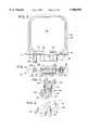
- FIG. 1is an exploded view of an ink supply that can be refilled using the method of the present invention.
- FIG. 2is a cross sectional view of the ink supply of FIG. 1.
- FIG. 3is a side view of the chassis of the ink supply of FIG. 1.
- FIG. 4is a bottom view of the chassis of FIG. 3.
- FIG. 5is a top perspective view of the pressure plate of the ink supply of FIG. 1.
- FIG. 6is a bottom perspective view of the pressure plate of FIG. 5.
- FIG. 7is an exploded, cross sectional view of an alternative pump for use in an ink supply that can be refilled using the method of the present invention.
- FIG. 8shows the ink supply of FIG. 1 being inserted into a docking bay of an ink-jet printer.
- FIG. 9is a cross sectional view of a part of the ink supply of FIG. 1 being inserted into the docking bay of an ink-jet printer.
- FIG. 10is a cross sectional view showing the ink supply of FIG. 9 fully inserted into the docking bay.
- FIGS. 11A-Dare cross-sectional views of the ink supply and docking bay showing the pump, actuator, and ink detector in various stages of operation, taken along line 11--11 of FIG. 10.
- FIG. 12illustrates the method of refilling of the present invention.
- FIG. 13is a cross sectional view, taken along line 13--13 of FIG. 12.
- FIG. 14is a cross sectional view, like FIG. 13, but of an alternative embodiment.
- FIG. 1An ink supply in accordance with a preferred embodiment of the present invention is illustrated in FIG. 1 as reference numeral 20.
- the ink supply 20has a chassis 22 which carries an ink reservoir 24 for containing ink, a pump 26 and fluid outlet 28.
- the chassis 22is enclosed within a hard protective shell 30 having a cap 32 affixed to its lower end.
- the cap 32is provided with an aperture 34 to allow access to the pump 26 and an aperture 36 to allow access to the fluid outlet 28.
- the ink supply 20is inserted into the docking bay 38 of an ink-jet printer, as illustrated in FIGS. 9 and 10.
- an actuator 40 within the docking bay 38is brought into contact with the pump 26 through aperture 34.
- a fluid inlet 42 within the docking bay 38is coupled to the fluid outlet 28 through aperture 36 to create a fluid path from the ink supply 20 to the pen. Operation of the actuator 40 causes the pump 26 to draw ink from the reservoir 24 and supply the ink through the fluid outlet 28 and the fluid inlet 42 to the pen.
- the ink supply 20can be easily removed from the docking bay 38. Upon removal, the fluid outlet 28 and the fluid inlet 42 close to help prevent any residual ink from leaking into the printer or onto the user. The ink supply 20 may then be refilled, discarded or stored for reinstallation at a later time. In this manner, the ink supply 20 provides a user of an ink-jet printer a simple, economical way to provide a reliable, and easily replaceable, supply of ink to an ink-jet printer.
- the chassis 22has a main body 44. Extending upward from the top of the chassis body 44 is a frame 46 which helps define and support the ink reservoir 24.
- the frame 46defines a generally square reservoir 24 having a thickness determined by the thickness of the frame 46 and having open sides. Each side of the frame 46 is provided with a face 48 to which a sheet of plastic 50 is attached to enclose the sides of the reservoir 24.
- the illustrated plastic sheetis flexible to allow the volume of the reservoir 24 to vary as ink is depleted from the reservoir 24. This helps to allow withdrawal and use of all of the ink within the reservoir 24 by reducing the amount of backpressure created as ink is depleted from the reservoir 24.
- the illustrated ink supply 20is intended to contain about 30 cubic centimeters of ink when full. Accordingly, the general dimensions of the ink reservoir defined by the frame are about 57 mm high, about 60 mm wide, and about 5.25 mm thick. These dimensions may vary depending on the desired size of the ink supply and the dimensions of the printer in which the ink supply is to be used.
- the plastic sheets 50are heat staked to the faces 48 of the frame in a manner well known to those in the art.
- the plastic sheets 50are, in the illustrated embodiment, multi-ply sheets having a an outer layer of low density polyethylene, a layer of adhesive, a layer of metallized polyethylene terephthalate, a layer of adhesive, a second layer of metallized polyethylene terephthalate, a layer of adhesive, and an inner layer of low density polyethylene.
- the layers of low density polyethyleneare about 0.0005 inches thick and the metallized polyethylene terephthalate is about 0.00048 inches thick.
- the low density polyethylene on the inner and outer sides of the plastic sheetscan be easily heat staked to the frame while the double layer of metallized polyethylene terephthalate provides a robust barrier against vapor loss and leakage.
- the double layer of metallized polyethylene terephthalateprovides a robust barrier against vapor loss and leakage.
- different materials, alternative methods of attaching the plastic sheets to the frame, or other types of reservoirsmight be used.
- the body 44 of the chassis 22, as seen in FIGS. 1-4,is provided with a fill port 52 to allow ink to be introduced into the reservoir 24.
- a plug 54is inserted into the fill port 52 to prevent the escape of ink through the fill port 52.
- the plug 54is a polypropylene ball that is press fit into the fill port 52.
- a pump 26is also carried on the body 44 of the chassis 22.
- the pump 26serves to pump ink from the reservoir 24 and supply it to the printer via the fluid outlet 28.
- the pump 26includes a pump chamber 56 that is integrally formed with the chassis 22.
- the pump chamber 56is defined by a skirt-like wall 58 which extends downwardly from the body 44 of the chassis 22.
- a pump inlet 60is formed at the top of the chamber 56 to allow fluid communication between the chamber 56 and the ink reservoir 24.
- a pump outlet 62 through which ink may be expelled from the chamber 56is also provided.
- a valve 64is positioned within the pump inlet 60. The valve 64 allows the flow of ink from the ink reservoir 24 into the chamber 56 but limits the flow of ink from the chamber 56 back into the ink reservoir 24. In this way, when the chamber is depressurized, ink may be drawn from the ink reservoir 24, through the pump inlet and into the chamber and when the chamber is pressurized ink within the chamber may be expelled through the pump outlet.
- the valve 64is a flapper valve positioned at the bottom of the pump inlet 60.
- the flapper valve 64illustrated in FIGS. 1 and 2, is a rectangular piece of flexible material.
- the valve 64is positioned over the bottom of the pump inlet 60 and heat staked to the chassis 22 at the midpoints of its short sides (the heat staked areas are darkened in the Figures).
- the unstaked sides of the valve 64each flex downward to allow the flow of ink around the valve 64, through the pump inlet 60, and into the chamber 56.
- the valve 64is configured to remain open as long as the chamber 56 is not pressurized.
- the flapper valve 64could be heat staked on only one side so that the entire valve 64 would flex about the staked side, or on three sides so that only one side of the valve 64 would flex.
- the flapper valve 64is made of a two ply material.
- the top plyis a layer of low density polyethylene 0.0015 inches thick.
- the bottom plyis a layer of polyethylene terephthalate (PET) 0.0005 inches thick.
- PETpolyethylene terephthalate
- the illustrated flapper valve 64is approximately 5.5 millimeters wide and 8.7 millimeters long. Of course, other materials or other sizes of valves may be used.
- a flexible diaphragm 66encloses the bottom of the chamber 56.
- the diaphragm 66is slightly larger than the opening at the bottom of the chamber 56 and is sealed around the bottom edge of the wall 58.
- the excess material in the oversized diaphragm 66allows the diaphragm 66 to flex up and down to vary the volume within the chamber 56.
- displacement of the diaphragm 66allows the volume of the chamber 56 to be varied by about 0.7 cubic centimeters.
- the fully expanded volume of the illustrated chamber 56is between about 2.2 and 2.5 cubic centimeters.
- the illustrated diaphragm 66is made of the same multi-ply material as the plastic sheets 50. Of course, other suitable materials may also be used to form the diaphragm 66.
- the diaphragm 66 in the illustrated embodimentis heat staked, using conventional methods, to the bottom edge of the skirt-like wall 58. During the heat staking process, the low density polyethylene in the diaphragm 66 seals any folds or wrinkles in the diaphragm 66 to create a leak proof connection.
- a pressure plate 68 and a spring 70are positioned within the chamber 56.
- the pressure plate 68illustrated in detail in FIGS. 5 and 6, has a smooth lower face 72 with a wall 74 extending upward about its perimeter.
- the central region 76 of the pressure plate 68is shaped to receive the lower end of the spring 70 and is provided with a spring retaining spike 78.
- Four wings 80extend laterally from an upper portion of the wall 74.
- the illustrated pressure plate 68is molded of high density polyethylene.
- the pressure plate 68is positioned within the chamber 56 with the lower face 72 adjacent the flexible diaphragm 66.
- the upper end of the spring 70which is stainless steel in the illustrated embodiment, is retained on a spike 82 formed in the chassis and the lower end of the spring 70 is retained on the spike 78 on the pressure plate 68.
- the springbiases the pressure plate 68 downward against the diaphragm 66 to increase the volume of the chamber.
- the wall 74 and wings 80serve to stabilize the orientation of the pressure plate 68 while allowing for its free, piston-like movement within the chamber 56.
- the pump 26includes a chamber 56a defined by a skirt-like wall 58a depending downwardly from the body 44a of the chassis.
- a flexible diaphragm 66ais attached to the lower edge of the wall 58a to enclose the lower end of the chamber 56a.
- a pump inlet 60a at the top of the chamber 56aextends from the chamber 56a into the ink reservoir 24a, and a pump outlet 62a allows ink to exit the chamber 56a.
- the pump inlet 60ahas a wide portion 86 opening into the chamber 56a, a narrow portion 88 opening into the ink reservoir, and a shoulder 90 joining the wide portion 86 to the narrow portion 88.
- a valve 64ais positioned in the pump inlet 60a to allow the flow of ink into the chamber 56a and limit the flow of ink from the chamber 56 back into the ink reservoir 24a.
- the valveis circular. However, other shaped valves, such as square or rectangular, could also be used.
- a unitary spring/pressure plate 92is positioned within the chamber 56a.
- the spring/pressure plate 92includes a flat lower face 94 that is positioned adjacent the diaphragm 66a, a spring portion 96 that biases the lower face downward, and a mounting stem 98 that is friction fit into the wide portion 86 of the pump inlet 60a.
- the spring portion 96is generally circular in configuration and is pre-stressed into a flexed position by the diaphragm 66a.
- the natural resiliency of the material used to construct the spring/pressure plate 92urges the spring to its original configuration, thereby biasing the lower face downward to expand the volume of the chamber 56a.
- the unitary spring/pressure plate 92may be formed of various suitable materials such as, for example, HYTREL.
- the valve 64ais a flapper valve that is held in position on the shoulder 90 of the pump inlet 60a by the top of the mounting stem 98.
- the mounting stem 98has a cross shape which allows the flapper valve 64a to deflect downward into four open quadrants to allow ink to flow from the ink reservoir 24a into the chamber.
- the shoulderprevents the flapper valve from deflecting in the upward direction to limit the flow of ink from the chamber back into the reservoir 24a. Rather, ink exits the chamber via the pump outlet 62.
- the mounting stemmay have a "V" cross section, an "I" cross section, or any other cross section which allows the flapper valve to flex sufficiently to permit the needed flow of ink into the chamber.
- a conduit 84joins the pump outlet 62 to the fluid outlet 28.
- the top wall of the conduit 84is formed by the lower member of the frame 46, the bottom wall is formed by the body 44 of the chassis 22; one side is enclosed by a portion of the chassis and the other side is enclosed by a portion of one of the plastic sheets 50.
- the fluid outlet 28is housed within a hollow cylindrical boss 99 that extends downward from the chassis 22.
- the top of the boss 99opens into the conduit 84 to allow ink to flow from the conduit 84 into the fluid outlet 28.
- a spring 100 and sealing ball 102are positioned within the boss 99 and are held in place by a compliant septum 104 and a crimp cover 106.
- the length of the spring 100is such that it can be placed into the inverted boss 99 with the ball 102 on top.
- the septum 104can then inserted be into the boss 99 to compress the spring 100 slightly so that the spring 100 biases the sealing ball 102 against the septum 104 to form a seal.
- the crimp cover 106fits over the septum 104 and engages an annular projection 108 on the boss 99 to hold the entire assembly in place.
- both the spring 100 and the ball 102are stainless steel.
- the sealing ball 102is sized such that it can move freely within the boss 99 and allow the flow of ink around the ball 102 when it is not in the sealing position.
- the septum 104is formed of polyisoprene rubber and has a concave bottom to receive a portion of the ball 102 to form a secure seal.
- the septum 104is provided with a slit 110 (FIG. 1) so that it may be easily pierced without tearing or coring. However, the slit 110 is normally closed such that the septum 104 itself forms a second seal.
- the slit 110may, preferably, be slightly tapered with its narrower end adjacent the ball 102.
- the illustrated crimp cover 106is formed of aluminum and has a thickness of about 0.020 inches. A hole 112 is provided so that the crimp cover 106 does not interfere with the piercing of the septum 104.
- the ink reservoir 24can be filled with ink.
- inkcan be injected through the fill port 52.
- a needle(not shown) can be inserted through the slit 110 in the septum 104 to depress the sealing ball 102 and allow the escape of any air from within the reservoir 24.
- a partial vacuumcan be applied through the needle.
- the partial vacuum at the fluid outlet 28causes ink from the reservoir 24 to fill the chamber 56, the conduit 84, and the cylindrical boss 99 such that little, if any, air remains in contact with the ink.
- the partial vacuum applied to the fluid outlet 28also speeds the filling process.
- any gas trapped within the ink supply 20 during the filling processwill be carbon dioxide, not air. This may be preferable because carbon dioxide may dissolve in some inks while air may not.
- the ink reservoir 24provides an ideal way to contain ink, it may be easily punctured or ruptured and may allow some amount of water loss from the ink. Accordingly, to protect the reservoir 24 and to further limit water loss, the reservoir 24 is enclosed within a protective shell 30.
- the illustrated shell 30is made of clarified polypropylene. A thickness of about one millimeter has been found to provide robust protection and to prevent unacceptable water loss from the ink. However, the material and thickness of the shell 30 may vary in other embodiments.
- the top of the shell 30has contoured gripping surfaces 114 that are shaped and textured to allow a user to easily grip and manipulate the ink supply 20.
- a vertical rib 116 having a detente 118 formed near its lower endprojects laterally from each side of the shell 30.
- the base of the shell 30is open to allow insertion of the chassis 22.
- a stop 120extends laterally outward from each side of wall 58 that defines the chamber 56. These stops 120 abut the lower edge of the shell 30 when the chassis 22 is inserted.
- the protective cap 32is fitted to the bottom of the shell 30 to maintain the chassis 22 in position.
- the cap 32is provided with recesses 128 which receive the stops 120 on the chassis 22. In this manner, the stops 120 are firmly secured between the cap 32 and the shell 30 to maintain the chassis 22 in position.
- the cap 32is also provided with an aperture 34 to allow access to the pump 26 and with an aperture 36 to allow access to the fluid outlet 28.
- the cap 32obscures the fill port 52 to help prevent tampering with the ink supply 20.
- One end of the cap 32is provided with projecting keys 130 which can identify the type or "family" of ink contained within the ink supply 20. For example, if the ink supply 20 is filled with ink suited for use with a particular printer or class of printers, a cap having keys of a selected number and spacing (in the illustrated embodiment, three evenly spaced apart keys are shown) to indicate that ink family is used.
- the other end of the cap 32is provided with a keyway 131 that, depending upon its particular location, size or both, is indicative of a certain color of ink, such as cyan, magenta, etc. Accordingly, if the ink supply 20 is filled with a particular color of ink, a cap having keyway(s) indicative of that color may be used. The color of the cap may also be used to indicate the color of ink contained within the ink supply 20.
- the chassis 22 and shell 30can be manufactured and assembled without regard to the particular type of ink they will contain. Then, after the ink reservoir 24 is filled, a cap indicative of the particular family and color of ink used is attached to the shell 30. This allows for manufacturing economies because a supply of empty chassis and shell 30 can be stored in inventory. Then when there is a demand for a particular type of ink, that ink can be introduced into the ink supply 20 and an appropriate cap fixed to the ink supply 20. Thus, this scheme reduces the need to maintain high inventories of ink supplies containing every type of ink.
- the bottom of the shell 30is provided with two circumferential grooves 122 which engage two circumferential ribs 124 formed on the cap 32 to secure the cap 32 to the shell 30. Sonic welding or some other mechanism may also be desirable to more securely fix the cap 32 to the shell 30.
- a labelcan be adhered to both the cap 32 and the shell 30 to more firmly secure them together. Pressure sensitive adhesive may be used to adhere the label in a manner that prevents the label from being peeled off and inhibits tampering with the ink supply 20.
- the attachment between the shell 30 and the cap 32should, preferably, be snug enough to prevent accidental separation of the cap 32 from the shell 30 and to resist the flow of ink from the shell 30 should the ink reservoir 24 develop a leak.
- the ingress of airshould be limited, however, in order to maintain a high humidity within the shell 30 and minimize water loss from the ink.
- the illustrated shell 30, and the flexible reservoir 24 which it contains,have the capacity to hold approximately thirty cubic centimeters of ink.
- the shell 30is approximately 67 millimeters wide, 15 millimeters thick, and 60 millimeters high. Of course, other dimensions and shapes can also be used depending on the particular needs of a given printer.
- the illustrated ink supply 20is ideally suited for insertion into a docking station 132 like that illustrated in FIGS. 8-10.
- the docking station 132 illustrated in FIG. 8is intended for use with a color printer. Accordingly, it has four side-by-side docking bays 38, each of which can receive one ink supply 20 of a different color.
- the structure of the illustrated ink supply 20allows for the supply to be relatively narrow in width. This allows for four ink supplies to be arranged side-by-side in a compact docking station without unduly increasing the "footprint" of the printer.
- Each docking bay 38includes opposing walls 134 and 136 which define inwardly facing vertical channels 138 and 140.
- a leaf spring 142 having an engagement prong 144is positioned within the lower portion of each channel 138 and 140.
- the engagement prong 144 of each leaf spring 142extends into the channel toward the docking bay 38 and is biased inward by the leaf spring.
- One of the channels 138is provided with keys 139 formed therein to mate with the keyway(s) 131 on one side of the ink supply cap 32.
- the other channel 140is provided with keyways 141 to mate with the keys 130 on the other side of the cap 32.
- a base plate 146defines the bottom of each docking bay 38.
- the base plate 146includes an aperture 148 which receives the actuator 40 and carries a housing 150 for the fluid inlet 42.
- the upper end of the actuatorextends upward through the aperture 148 in the base plate 146 and into the docking bay 38.
- the lower portion of the actuator 40is positioned below the base plate and is pivotably coupled to one end of a lever 152 which is supported on pivot point 154.
- the other end of the lever 154is biased downward by a compression spring 156.
- a cam 158 mounted on a rotatable shaft 160is positioned such that rotation of the shaft 160 to an engaged position causes the cam 158 to overcome the force of the compression spring 156 and move the actuator 40 downward. Movement of the actuator 40, as explained in more detail below, causes the pump 26 to draw ink from the reservoir 24 and supply it through the fluid outlet 28 and the fluid inlet 42 to the printer.
- the fluid inlet 42is positioned within the housing 150 carried on the base plate 146.
- the illustrated fluid inlet 42includes an upwardly extending needle 162 having a closed blunt upper end 164, a blind bore 166 and a lateral hole 168.
- a trailing tube(not shown) is connected to the lower end of the needle 162 such that the blind bore 166 is in fluid communication therewith.
- the trailing tubeleads to a print head (not shown).
- the print headwill usually include a small ink well for maintaining a small quantity of ink and some type of pressure regulator to maintain an appropriate pressure within the ink well. Typically, it is desired that the pressure within the ink well be slightly less than ambient. This "back pressure" helps to prevent ink from dripping from the print head.
- the pressure regulator at the print headmay commonly include a check valve which prevents the return flow of ink from the print head and into the trailing tube.
- a sliding collar 170surrounds the needle 162 and is biased upwardly by a spring 172.
- the sliding collar 170has a compliant sealing portion 174 with an exposed upper surface 176 and an inner surface 178 in direct contact with the needle 162.
- the illustrated sliding collarincludes a substantially rigid portion 180 extending downwardly to partially house the spring 172.
- An annular stop 182extends outward from the lower edge of the substantially rigid portion 180. The annular stop 182 is positioned beneath the base plate 146 such that it abuts the base plate 146 to limit upward travel of the sliding collar 170 and define an upper position of the sliding collar 170 on the needle 162. In the upper position, the lateral hole 168 is surrounded by the sealing portion 174 of the collar 170 to seal the lateral hole 168 and the blunt end 164 of the needle 162 is generally even with the upper surface 176 of the collar 170.
- the needle 162is an eighteen gauge stainless steel needle with an inside diameter of about 1.04 millimeters, an outside diameter of about 1.2 millimeters, and a length of about 30 millimeters.
- the lateral hole 168is generally rectangular with dimensions of about 0.55 millimeters by 0.70 millimeters and is located about 1.2 millimeters from the upper end of the needle 162.
- the sealing portion 174 of the sliding collar 170is made of ethylene propylene dimer monomer and the generally rigid portion 176 is made of polypropylene or any other suitably rigid material.
- the sealing portion 174is molded with an aperture to snugly receive the needle 162 and form a robust seal between the inner surface 178 and the needle 162. Alternative dimensions, materials or configurations might also be used.
- an ink supply 20within the docking bay 38, a user can simply place the lower end of the ink supply 20 between the opposing walls 134 and 136 with one edge in one vertical channel 138 and the other edge in the other vertical channel 140, as shown in FIGS. 8 and 9.
- the ink supply 20is then pushed downward into the installed position, shown in FIG. 10, in which the bottom of the cap 32 abuts the base plate 146.
- the fluid outlet 28 and fluid inlet 42automatically engage and open to form a path for fluid flow from the ink supply 20 to the printer, as explained in more detail below.
- the actuator 40enters the aperture 34 in the cap 32 to pressurize the pump 26, as explained in more detail below.
- the engagement prongs 144 on each side of the docking stationengage the detentes 118 formed in the shell 30 to firmly hold the ink supply 20 in place.
- the leaf springs 142which allow the engagement prongs 144 to move outward during insertion of the ink supply 20, bias the engagement prongs 144 inward to positively hold the ink supply 20 in the installed position.
- the edges of the ink supply 20are captured within the vertical channels 138 and 140 which provide lateral support and stability to the ink supply 20.
- FIG. 9shows the fluid outlet 28 upon its initial contact with the fluid inlet 42.
- the housing 150has partially entered the cap 32 through aperture 36 and the lower end of the fluid outlet 28 has entered into the top of the housing 150.
- the crimp cover 106contacts the sealing collar 170 to form a seal between the fluid outlet 28 and the fluid inlet 42 while both are still in their sealed positions. This seal acts as a safety barrier in the event that any ink should leak through the septum 104 or from the needle 162 during the coupling and decoupling process.
- the bottom of the fluid inlet 42 and the top of the fluid outlet 28are both generally planar. Thus, very little air is trapped within the seal between the fluid outlet 28 of the ink supply 20 and the fluid inlet 42 of the printer. This facilitates proper operation of the printer by reducing the possibility that air will enter the fluid outlet 28 or the fluid inlet 42 and reach the ink-jets in the print head.
- the bottom of the fluid outlet 28pushes the sliding collar 170 downward, as illustrated in FIG. 10.
- the needle 162enters the slit 110 and passes through the septum 104 to depress the sealing ball 102.
- inkcan flow from the boss 99, around the sealing ball 102, into the lateral hole 168, down the bore 166, through the trailing tube 169 to the print head.
- the needle 162Upon removal of the ink supply 20, the needle 162 is withdrawn and the spring 100 presses the sealing ball 102 firmly against the septum 104 to establish a robust seal.
- the slit 110closes to establish a second seal, both of which serve to prevent ink from leaking through the fluid outlet 28.
- the spring 172pushes the sliding collar 170 back to its upper position in which the lateral hole 168 is encased within the sealing portion of the collar 170 to prevent the escape of ink from the fluid inlet 42.
- the seal between the crimp cover 106 and the upper surface 176 of the sliding collar 170is broken. With this fluid interconnect, little, if any, ink is exposed when the fluid outlet 28 is separated from the fluid inlet 42. This helps to keep both the user and the printer clean.
- fluid outlet 28 and fluid inlet 42provide a secure seal with little entrapped air upon sealing and little excess ink upon unsealing, other fluid interconnections might also be used to connect the ink supply 20 to the printer.
- FIGS. 11A-Dillustrate various stages of the pump's operation.
- FIG. 11Aillustrates the fully charged position of the pump 26.
- the flexible diaphragm 66is in its lowermost position, and the volume of the chamber 56 is at its maximum.
- the actuator 40is pressed against the diaphragm 66 by the compression spring 156 to urge the chamber 56 to a reduced volume and create pressure within the pump chamber 56.
- the valve 64closes to prevent the flow of ink from the chamber 56 back into the reservoir 24, causing the ink to pass from the chamber 56 through the pump outlet 62 and the conduit 84 to the fluid outlet 28.
- the compression spring 156is chosen so as to create a pressure of about 1.5 pounds per square inch within the chamber 56.
- the desired pressuremay vary depending on the requirements of a particular printer and may vary through the pump stroke.
- the pressure within the chamberwill vary from about 90-45 inches of water column during the pump stroke.
- the compression spring 156continues to press the actuator 40 upward against the diaphragm 66 to maintain a pressure within the pump chamber 56. This causes the diaphragm 66 to move upward to an intermediate position decreasing the volume of the chamber 56, as illustrated in FIG. 11B.
- the diaphragm 66is pressed to its uppermost position, illustrated in FIG. 11C. In the uppermost position, the volume of the chamber 56 is at its minimum operational volume.
- the pump spring 70biases the pressure plate 68 and diaphragm 66 outward, expanding the volume and decreasing the pressure within the chamber 56.
- the valve 64With decreased pressure within the chamber 56, the valve 64 is open and ink is drawn from the reservoir 24 into the chamber 56 to refresh the pump 26, as illustrated in FIG. 11D.
- the check valve at the print head, the flow resistance within the trailing tube, or both,will limit ink from returning to the chamber 56 through the conduit 84.
- a check valvemay be provided at the outlet port, or at some other location, to prevent the return of ink through the outlet port and into the chamber 56.
- the refresh cycleis concluded by rotating the cam 158 back into its disengaged position and the ink supply 20 typically returns to the configuration illustrated in FIG. 11A.
- the configuration of the ink supply 20is particularly advantageous because only the relatively small amount of ink within the chamber 56 is pressurized when the actuator is engaged with the diaphragm 66.
- the large majority of the inkis maintained within the reservoir 24 at approximately ambient pressure. Thus, it is less likely to leak and, in the event of a leak, can be more easily contained.
- the illustrated diaphragm pumphas proven to be very reliable and well suited for use in the ink supply 20.
- other types of pumpsmay also be used.
- a piston pump, a bellows pump, or other types of pumpsmight be adapted for use with the present invention.
- the ink supply 20having a valve 64, a chamber 56 and a fluid outlet 28, as just described, is refilled once depleted.
- the ink supply 20is removed from the docking bay 38 for refilling.
- the diaphragm 66is no longer in contact with the actuator 40, which allows the chamber 56 to expand to its maximum volume and removes the chamber pressure applied by the actuator 40.
- the unattached sides of the valve 64are free to bend downward, slightly opening the valve 64 (see FIG. 13).
- the bend in the valve 64 that occurs in the absence of pressure (other than the static ink pressure) in the chamber 56is attributable to the slight deformation of the valve 64 that results as ink is normally pumped through the valve 64 into the chamber 56, forcing the valve 64 into an open, bent configuration.
- valve 64under static conditions (i.e., the actuator in the disengaged position), assumes a slightly open position. With the valve 64 so positioned, a gradual, low-pressure flow of refill ink may be directed through the valve 64 into the reservoir 24, as depicted in FIG. 13 and explained more fully below.
- the ink supply 20 to be refilledmay be placed in a stabilizing base 202, as shown in FIG. 12, or held steady by hand.
- the pumpis permitted to assume the fully charged position, so that chamber 56 is essentially unpressurized.
- a refill needle 200is inserted into the slit in the septum 104 of the fluid outlet 28.
- the refill needle 200is configured as the previously described needle 162 of the fluid inlet 42. Other configurations for a refill needle could be used.
- the needle 200emanates from a source of refill ink that provides ink having the appropriate physical and chemical characteristics of the originally supplied ink.
- Insertion of the refill needle 200depresses the sealing ball 102 and the spring 100, thereby opening a path for ink flow through the fluid outlet 28, conduit 84, into the chamber 56.
- the valve 64is slightly open and, thus, a complete path is available for flow of refill ink from the fluid outlet 28, through conduit 84, into chamber 56, through inlet 60, and into the reservoir 24 as shown by the arrows in FIG. 12.
- the rate at which the refill ink is suppliedis selected to be sufficiently slow, so that the valve 64 remains open during the entire refill process.
- the refill flow from an ink refill containermay be induced by gravity, with the refill container elevated by an amount sufficient to create a pressure head to refill the reservoir 24 without forcing the valve 64 closed.
- the method of the present inventionis also useful for refilling an ink supply having a valve that is heat staked to the chassis 22 at a location other than the midpoints of its short sides.
- the present methodcould be used on a valve 64b that is heat staked to the chassis 22 on only one side, as shown in FIG. 14.
- the valve 64bwould be likely to remain in a slightly deformed, open state that creates a relatively larger gap to allow refill ink flow into the reservoir 24.
- the method of the present inventioncould be used for refilling an ink supply having a unitary spring/pressure plate 92 as shown in FIG. 7 and described previously.
Landscapes
- Ink Jet (AREA)
Abstract
Description
The present invention relates to a method for refilling a reusable ink supply having a pressurized chamber.
A typical ink-jet printer has a pen mounted to a carriage that traverses a printing surface, such as a piece of paper. The pen carries a print head. As the print head passes over appropriate locations on the printing surface, a control system activates ink-jets on the print head to eject, or jet, ink drops onto the printing surface and form desired images and characters.
To work properly, such printers must have a reliable supply of ink for the print head. Many ink-jet printers use a disposable ink pen that can be mounted to the carriage. Such an ink pen typically includes, in addition to the print head, a reservoir containing a supply of ink. The ink pen also typically includes pressure regulating mechanisms to maintain the ink supply at an appropriate pressure for use by the print head. When the ink supply is exhausted, the ink pen is disposed of and a new ink pen is installed. This system provides an easy, user friendly way of providing an ink supply for an ink-jet printer.
However, in a printer using an ink pen, the entire ink pen, including the reservoir and ink supply, is moved with the print head. This requires a trade-off. If the ink pen has a large reservoir and ink supply, it is heavier and is more difficult to move quickly. This may limit the speed with which the printer can print--an important characteristic of a printer. On the other hand, if the ink pen has a small reservoir and ink supply, it will be depleted more quickly and require more frequent replacement.
The problems posed by size limitations of the ink reservoir have been heightened by the increasing popularity of color printers. In a color printer, it is usually necessary to supply more than one color of ink to the print head. Commonly, three or four different ink colors, each of which must be contained in a separate reservoir, are required. The combined volume of all of these reservoirs is limited in the same manner as the single reservoir of a typical one-color printer. Thus, each reservoir can be only a fraction of the size of a typical reservoir for a one-color printer.
Furthermore, when even one of the reservoirs is depleted, the ink pen may no longer be able to print as intended. Thus, the ink pen must typically be replaced and discarded, or at least removed for refilling, when the first of the reservoirs is exhausted. This further decreases the useful life of the ink pen.
As can be appreciated, the print head and pressure regulating mechanism of the ink pen contribute substantially to the cost of the ink pen. These mechanisms can also have a useful life expectancy far longer than the supply of ink in the reservoir. Thus, when the ink pen is discarded, the print head and pressure regulating mechanisms may have a great deal of usable life remaining. In addition, in multiple color ink pens, it is unlikely that all of the ink reservoirs will be depleted at the same time. Thus, the discarded ink pen will likely contain unused ink as well as a fully functional print head and pressure regulating mechanism. This results in increased cost to the user and a somewhat wasteful and inefficient use of resources.
To alleviate some of the shortcomings of disposable ink pens, some ink-jet printers have used ink supplies that are not mounted to the carriage. Such ink supplies, because they are stationary within the printer, are not subject to all of the size limitations of an ink supply that is moved with the carriage. Some printers with stationary ink supplies have a refillable ink reservoir built into the printer. Ink is supplied from the reservoir to the print head through a tube which trails from the print head. Alternatively, the print head can include a small ink reservoir that is periodically replenished by moving the print head to a filling station at the stationary, built-in reservoir. In either alternative, ink may be supplied from the reservoir to the print head by either a pump within the printer or by gravity flow.
However, such built-in reservoirs are frequently difficult and messy to refill. In addition, because they are never replaced, built-in ink reservoirs tend to collect particles and contaminants that can adversely affect printer performance.
In view of these problems, some printers use replaceable reservoirs. These reservoirs, like the built-in reservoirs are not located on the carriage and, thus, are not moved with the print head during printing. Replaceable reservoirs sometimes are plastic bags filled with ink. The bag is provided with a mechanism, such as a septum which can be punctured by a hollow needle, for coupling it to the printer so that ink may flow from the bag to the print head. Often, the bag is squeezed, or pressurized in some other manner, to cause the ink to flow from the reservoir. Should the bag burst or leak while under pressure, the consequences can be catastrophic for the printer.
One particular replaceable reservoir reliably supplies ink to the print head, yet is not complicated and can be manufactured simply and inexpensively. This reservoir is also easily recyclable.
The replaceable reservoir has an ink supply that has a main reservoir for holding a supply of ink. The main reservoir, which is typically maintained at about ambient pressure, is coupled to a variable volume chamber via a valve that allows the flow of ink from the reservoir to the chamber and limits the flow of ink from the chamber to the reservoir. The chamber is coupled to a fluid outlet which is normally closed to prevent the flow of ink. However, when the ink supply is installed in a printer, the fluid outlet opens to establish a fluid connection between the chamber and the pen.
The chamber can serve as part of a pump to supply ink from the reservoir to the pen. In particular, when the volume of the chamber is increased, ink is drawn from the reservoir through the valve and into the chamber. When the volume of the chamber is decreased, ink is forced from the chamber through the fluid outlet to supply the print head.
The reservoir includes flexible plastic walls supported by a rigid frame. The frame is carried by a chassis which also carries the variable volume chamber and the fluid outlet.
The present invention is particularly directed to a method for refilling an ink supply of the type described above. This allows the ink supply container to be reused.
The present method involves supplying refill ink into the ink supply container through the fluid outlet that otherwise, during normal operation, serves to direct the ink from the supply to the pen.
Other objects and aspects of the invention will become apparent to those skilled in the art from the detailed description of the invention which is presented by way of example and not as a limitation of the present invention.
FIG. 1 is an exploded view of an ink supply that can be refilled using the method of the present invention.
FIG. 2 is a cross sectional view of the ink supply of FIG. 1.
FIG. 3 is a side view of the chassis of the ink supply of FIG. 1.
FIG. 4 is a bottom view of the chassis of FIG. 3.
FIG. 5 is a top perspective view of the pressure plate of the ink supply of FIG. 1.
FIG. 6 is a bottom perspective view of the pressure plate of FIG. 5.
FIG. 7 is an exploded, cross sectional view of an alternative pump for use in an ink supply that can be refilled using the method of the present invention.
FIG. 8 shows the ink supply of FIG. 1 being inserted into a docking bay of an ink-jet printer.
FIG. 9 is a cross sectional view of a part of the ink supply of FIG. 1 being inserted into the docking bay of an ink-jet printer.
FIG. 10 is a cross sectional view showing the ink supply of FIG. 9 fully inserted into the docking bay.
FIGS. 11A-D are cross-sectional views of the ink supply and docking bay showing the pump, actuator, and ink detector in various stages of operation, taken along line 11--11 of FIG. 10.
FIG. 12 illustrates the method of refilling of the present invention.
FIG. 13 is a cross sectional view, taken alongline 13--13 of FIG. 12.
FIG. 14 is a cross sectional view, like FIG. 13, but of an alternative embodiment.
An ink supply in accordance with a preferred embodiment of the present invention is illustrated in FIG. 1 asreference numeral 20. Theink supply 20 has achassis 22 which carries anink reservoir 24 for containing ink, apump 26 andfluid outlet 28. Thechassis 22 is enclosed within a hardprotective shell 30 having acap 32 affixed to its lower end. Thecap 32 is provided with anaperture 34 to allow access to thepump 26 and anaperture 36 to allow access to thefluid outlet 28.
In use, theink supply 20 is inserted into thedocking bay 38 of an ink-jet printer, as illustrated in FIGS. 9 and 10. Upon insertion of theink supply 20, anactuator 40 within thedocking bay 38 is brought into contact with thepump 26 throughaperture 34. In addition, afluid inlet 42 within thedocking bay 38 is coupled to thefluid outlet 28 throughaperture 36 to create a fluid path from theink supply 20 to the pen. Operation of theactuator 40 causes thepump 26 to draw ink from thereservoir 24 and supply the ink through thefluid outlet 28 and thefluid inlet 42 to the pen.
Upon depletion of the ink from thereservoir 24, or for any other reason, theink supply 20 can be easily removed from thedocking bay 38. Upon removal, thefluid outlet 28 and thefluid inlet 42 close to help prevent any residual ink from leaking into the printer or onto the user. Theink supply 20 may then be refilled, discarded or stored for reinstallation at a later time. In this manner, theink supply 20 provides a user of an ink-jet printer a simple, economical way to provide a reliable, and easily replaceable, supply of ink to an ink-jet printer.
As illustrated in FIGS. 1-3, thechassis 22 has amain body 44. Extending upward from the top of thechassis body 44 is aframe 46 which helps define and support theink reservoir 24. In the illustrated embodiment, theframe 46 defines a generallysquare reservoir 24 having a thickness determined by the thickness of theframe 46 and having open sides. Each side of theframe 46 is provided with aface 48 to which a sheet ofplastic 50 is attached to enclose the sides of thereservoir 24. The illustrated plastic sheet is flexible to allow the volume of thereservoir 24 to vary as ink is depleted from thereservoir 24. This helps to allow withdrawal and use of all of the ink within thereservoir 24 by reducing the amount of backpressure created as ink is depleted from thereservoir 24. The illustratedink supply 20, is intended to contain about 30 cubic centimeters of ink when full. Accordingly, the general dimensions of the ink reservoir defined by the frame are about 57 mm high, about 60 mm wide, and about 5.25 mm thick. These dimensions may vary depending on the desired size of the ink supply and the dimensions of the printer in which the ink supply is to be used.
In the illustrated embodiment, theplastic sheets 50 are heat staked to thefaces 48 of the frame in a manner well known to those in the art. Theplastic sheets 50 are, in the illustrated embodiment, multi-ply sheets having a an outer layer of low density polyethylene, a layer of adhesive, a layer of metallized polyethylene terephthalate, a layer of adhesive, a second layer of metallized polyethylene terephthalate, a layer of adhesive, and an inner layer of low density polyethylene. The layers of low density polyethylene are about 0.0005 inches thick and the metallized polyethylene terephthalate is about 0.00048 inches thick. The low density polyethylene on the inner and outer sides of the plastic sheets can be easily heat staked to the frame while the double layer of metallized polyethylene terephthalate provides a robust barrier against vapor loss and leakage. Of course, in other embodiments, different materials, alternative methods of attaching the plastic sheets to the frame, or other types of reservoirs might be used.
Thebody 44 of thechassis 22, as seen in FIGS. 1-4, is provided with afill port 52 to allow ink to be introduced into thereservoir 24. After filling thereservoir 24, aplug 54 is inserted into thefill port 52 to prevent the escape of ink through thefill port 52. In the illustrated embodiment, theplug 54 is a polypropylene ball that is press fit into thefill port 52.
Apump 26 is also carried on thebody 44 of thechassis 22. Thepump 26 serves to pump ink from thereservoir 24 and supply it to the printer via thefluid outlet 28. In the illustrated embodiment, seen in FIGS. 1 and 2, thepump 26 includes apump chamber 56 that is integrally formed with thechassis 22. Thepump chamber 56 is defined by a skirt-like wall 58 which extends downwardly from thebody 44 of thechassis 22.
Apump inlet 60 is formed at the top of thechamber 56 to allow fluid communication between thechamber 56 and theink reservoir 24. Apump outlet 62 through which ink may be expelled from thechamber 56 is also provided. Avalve 64 is positioned within thepump inlet 60. Thevalve 64 allows the flow of ink from theink reservoir 24 into thechamber 56 but limits the flow of ink from thechamber 56 back into theink reservoir 24. In this way, when the chamber is depressurized, ink may be drawn from theink reservoir 24, through the pump inlet and into the chamber and when the chamber is pressurized ink within the chamber may be expelled through the pump outlet. In the illustrated embodiment, thevalve 64 is a flapper valve positioned at the bottom of thepump inlet 60. Theflapper valve 64, illustrated in FIGS. 1 and 2, is a rectangular piece of flexible material. Thevalve 64 is positioned over the bottom of thepump inlet 60 and heat staked to thechassis 22 at the midpoints of its short sides (the heat staked areas are darkened in the Figures). When the pressure within thechamber 56 drops sufficiently below that in thereservoir 24, the unstaked sides of thevalve 64 each flex downward to allow the flow of ink around thevalve 64, through thepump inlet 60, and into thechamber 56. Thevalve 64 is configured to remain open as long as thechamber 56 is not pressurized. In alternative configurations, theflapper valve 64 could be heat staked on only one side so that theentire valve 64 would flex about the staked side, or on three sides so that only one side of thevalve 64 would flex.
In the illustrated embodiment, theflapper valve 64 is made of a two ply material. The top ply is a layer of low density polyethylene 0.0015 inches thick. The bottom ply is a layer of polyethylene terephthalate (PET) 0.0005 inches thick. The illustratedflapper valve 64 is approximately 5.5 millimeters wide and 8.7 millimeters long. Of course, other materials or other sizes of valves may be used.
Aflexible diaphragm 66 encloses the bottom of thechamber 56. Thediaphragm 66 is slightly larger than the opening at the bottom of thechamber 56 and is sealed around the bottom edge of thewall 58. The excess material in theoversized diaphragm 66 allows thediaphragm 66 to flex up and down to vary the volume within thechamber 56. In the illustratedink supply 20, displacement of thediaphragm 66 allows the volume of thechamber 56 to be varied by about 0.7 cubic centimeters. The fully expanded volume of the illustratedchamber 56 is between about 2.2 and 2.5 cubic centimeters.
The illustrateddiaphragm 66 is made of the same multi-ply material as theplastic sheets 50. Of course, other suitable materials may also be used to form thediaphragm 66. Thediaphragm 66 in the illustrated embodiment is heat staked, using conventional methods, to the bottom edge of the skirt-like wall 58. During the heat staking process, the low density polyethylene in thediaphragm 66 seals any folds or wrinkles in thediaphragm 66 to create a leak proof connection.
Apressure plate 68 and aspring 70 are positioned within thechamber 56. Thepressure plate 68, illustrated in detail in FIGS. 5 and 6, has a smoothlower face 72 with awall 74 extending upward about its perimeter. Thecentral region 76 of thepressure plate 68 is shaped to receive the lower end of thespring 70 and is provided with aspring retaining spike 78. Fourwings 80 extend laterally from an upper portion of thewall 74. The illustratedpressure plate 68 is molded of high density polyethylene.
Thepressure plate 68 is positioned within thechamber 56 with thelower face 72 adjacent theflexible diaphragm 66. The upper end of thespring 70, which is stainless steel in the illustrated embodiment, is retained on aspike 82 formed in the chassis and the lower end of thespring 70 is retained on thespike 78 on thepressure plate 68. In this manner, the spring biases thepressure plate 68 downward against thediaphragm 66 to increase the volume of the chamber. Thewall 74 andwings 80 serve to stabilize the orientation of thepressure plate 68 while allowing for its free, piston-like movement within thechamber 56.
An alternative embodiment of thepump 26 is illustrated in FIG. 7. In this embodiment, thepump 26 includes achamber 56a defined by a skirt-like wall 58a depending downwardly from thebody 44a of the chassis. Aflexible diaphragm 66a is attached to the lower edge of thewall 58a to enclose the lower end of thechamber 56a. Apump inlet 60a at the top of thechamber 56a extends from thechamber 56a into the ink reservoir 24a, and apump outlet 62a allows ink to exit thechamber 56a. Thepump inlet 60a has awide portion 86 opening into thechamber 56a, anarrow portion 88 opening into the ink reservoir, and ashoulder 90 joining thewide portion 86 to thenarrow portion 88. A valve 64a is positioned in thepump inlet 60a to allow the flow of ink into thechamber 56a and limit the flow of ink from thechamber 56 back into the ink reservoir 24a. In the illustrated embodiment, the valve is circular. However, other shaped valves, such as square or rectangular, could also be used.
In the embodiment of FIG. 7, a unitary spring/pressure plate 92 is positioned within thechamber 56a. The spring/pressure plate 92 includes a flatlower face 94 that is positioned adjacent thediaphragm 66a, aspring portion 96 that biases the lower face downward, and a mountingstem 98 that is friction fit into thewide portion 86 of thepump inlet 60a. In the illustrated embodiment, thespring portion 96 is generally circular in configuration and is pre-stressed into a flexed position by thediaphragm 66a. The natural resiliency of the material used to construct the spring/pressure plate 92 urges the spring to its original configuration, thereby biasing the lower face downward to expand the volume of thechamber 56a. The unitary spring/pressure plate 92 may be formed of various suitable materials such as, for example, HYTREL.
In this embodiment, the valve 64a is a flapper valve that is held in position on theshoulder 90 of thepump inlet 60a by the top of the mountingstem 98. The mountingstem 98 has a cross shape which allows the flapper valve 64a to deflect downward into four open quadrants to allow ink to flow from the ink reservoir 24a into the chamber. The shoulder prevents the flapper valve from deflecting in the upward direction to limit the flow of ink from the chamber back into the reservoir 24a. Rather, ink exits the chamber via thepump outlet 62. It should be appreciated that the mounting stem may have a "V" cross section, an "I" cross section, or any other cross section which allows the flapper valve to flex sufficiently to permit the needed flow of ink into the chamber.
As illustrated in FIG. 2, aconduit 84 joins thepump outlet 62 to thefluid outlet 28. In the illustrated embodiment, the top wall of theconduit 84 is formed by the lower member of theframe 46, the bottom wall is formed by thebody 44 of thechassis 22; one side is enclosed by a portion of the chassis and the other side is enclosed by a portion of one of theplastic sheets 50.
As illustrated in FIGS. 1 and 2, thefluid outlet 28 is housed within a hollowcylindrical boss 99 that extends downward from thechassis 22. The top of theboss 99 opens into theconduit 84 to allow ink to flow from theconduit 84 into thefluid outlet 28. Aspring 100 and sealingball 102 are positioned within theboss 99 and are held in place by acompliant septum 104 and acrimp cover 106. The length of thespring 100 is such that it can be placed into theinverted boss 99 with theball 102 on top. Theseptum 104 can then inserted be into theboss 99 to compress thespring 100 slightly so that thespring 100 biases the sealingball 102 against theseptum 104 to form a seal. Thecrimp cover 106 fits over theseptum 104 and engages anannular projection 108 on theboss 99 to hold the entire assembly in place.
In the illustrated embodiment, both thespring 100 and theball 102 are stainless steel. The sealingball 102 is sized such that it can move freely within theboss 99 and allow the flow of ink around theball 102 when it is not in the sealing position. Theseptum 104 is formed of polyisoprene rubber and has a concave bottom to receive a portion of theball 102 to form a secure seal. Theseptum 104 is provided with a slit 110 (FIG. 1) so that it may be easily pierced without tearing or coring. However, theslit 110 is normally closed such that theseptum 104 itself forms a second seal. Theslit 110 may, preferably, be slightly tapered with its narrower end adjacent theball 102. The illustratedcrimp cover 106 is formed of aluminum and has a thickness of about 0.020 inches. Ahole 112 is provided so that thecrimp cover 106 does not interfere with the piercing of theseptum 104.
With the pump andfluid outlet 28 in place, theink reservoir 24 can be filled with ink. To fill theink reservoir 24, ink can be injected through thefill port 52. As ink is being introduced into thereservoir 24, a needle (not shown) can be inserted through theslit 110 in theseptum 104 to depress the sealingball 102 and allow the escape of any air from within thereservoir 24. Alternatively, a partial vacuum can be applied through the needle. The partial vacuum at thefluid outlet 28 causes ink from thereservoir 24 to fill thechamber 56, theconduit 84, and thecylindrical boss 99 such that little, if any, air remains in contact with the ink. The partial vacuum applied to thefluid outlet 28 also speeds the filling process. Once theink supply 20 is filled, theplug 54 is press fit into thefill port 52 to prevent the escape of ink or the entry of air.
Of course, there are a variety of other methods which might also be used to fill thepresent ink supply 20. In some instances, it may be desirable to flush theentire ink supply 20 with carbon dioxide prior to filling it with ink. In this way, any gas trapped within theink supply 20 during the filling process will be carbon dioxide, not air. This may be preferable because carbon dioxide may dissolve in some inks while air may not. In general, it is preferable to remove as much gas from theink supply 20 as possible so that bubbles and the like do not enter the print head or the trailing tube. To this end, it may also be preferable to use degassed ink to further avoid the creation or presence of bubbles in theink supply 20.
Although theink reservoir 24 provides an ideal way to contain ink, it may be easily punctured or ruptured and may allow some amount of water loss from the ink. Accordingly, to protect thereservoir 24 and to further limit water loss, thereservoir 24 is enclosed within aprotective shell 30. The illustratedshell 30 is made of clarified polypropylene. A thickness of about one millimeter has been found to provide robust protection and to prevent unacceptable water loss from the ink. However, the material and thickness of theshell 30 may vary in other embodiments.
As illustrated in FIG. 1, the top of theshell 30 has contouredgripping surfaces 114 that are shaped and textured to allow a user to easily grip and manipulate theink supply 20. Avertical rib 116 having adetente 118 formed near its lower end projects laterally from each side of theshell 30. The base of theshell 30 is open to allow insertion of thechassis 22. Astop 120 extends laterally outward from each side ofwall 58 that defines thechamber 56. These stops 120 abut the lower edge of theshell 30 when thechassis 22 is inserted.
Theprotective cap 32 is fitted to the bottom of theshell 30 to maintain thechassis 22 in position. Thecap 32 is provided withrecesses 128 which receive thestops 120 on thechassis 22. In this manner, thestops 120 are firmly secured between thecap 32 and theshell 30 to maintain thechassis 22 in position. Thecap 32 is also provided with anaperture 34 to allow access to thepump 26 and with anaperture 36 to allow access to thefluid outlet 28. Thecap 32 obscures thefill port 52 to help prevent tampering with theink supply 20.
One end of thecap 32 is provided with projectingkeys 130 which can identify the type or "family" of ink contained within theink supply 20. For example, if theink supply 20 is filled with ink suited for use with a particular printer or class of printers, a cap having keys of a selected number and spacing (in the illustrated embodiment, three evenly spaced apart keys are shown) to indicate that ink family is used.
The other end of thecap 32 is provided with a keyway 131 that, depending upon its particular location, size or both, is indicative of a certain color of ink, such as cyan, magenta, etc. Accordingly, if theink supply 20 is filled with a particular color of ink, a cap having keyway(s) indicative of that color may be used. The color of the cap may also be used to indicate the color of ink contained within theink supply 20.
As a result of this structure, thechassis 22 andshell 30 can be manufactured and assembled without regard to the particular type of ink they will contain. Then, after theink reservoir 24 is filled, a cap indicative of the particular family and color of ink used is attached to theshell 30. This allows for manufacturing economies because a supply of empty chassis andshell 30 can be stored in inventory. Then when there is a demand for a particular type of ink, that ink can be introduced into theink supply 20 and an appropriate cap fixed to theink supply 20. Thus, this scheme reduces the need to maintain high inventories of ink supplies containing every type of ink.
As illustrated, the bottom of theshell 30 is provided with twocircumferential grooves 122 which engage twocircumferential ribs 124 formed on thecap 32 to secure thecap 32 to theshell 30. Sonic welding or some other mechanism may also be desirable to more securely fix thecap 32 to theshell 30. In addition, a label can be adhered to both thecap 32 and theshell 30 to more firmly secure them together. Pressure sensitive adhesive may be used to adhere the label in a manner that prevents the label from being peeled off and inhibits tampering with theink supply 20.
The attachment between theshell 30 and thecap 32 should, preferably, be snug enough to prevent accidental separation of thecap 32 from theshell 30 and to resist the flow of ink from theshell 30 should theink reservoir 24 develop a leak. However, it is also desirable that the attachment allow the slow ingress of air into theshell 30 as ink is depleted from thereservoir 24 to maintain the pressure inside theshell 30 generally the same as the ambient pressure. Otherwise, a negative pressure may develop inside theshell 30 and inhibit the flow of ink from thereservoir 24. The ingress of air should be limited, however, in order to maintain a high humidity within theshell 30 and minimize water loss from the ink.
The illustratedshell 30, and theflexible reservoir 24 which it contains, have the capacity to hold approximately thirty cubic centimeters of ink. Theshell 30 is approximately 67 millimeters wide, 15 millimeters thick, and 60 millimeters high. Of course, other dimensions and shapes can also be used depending on the particular needs of a given printer.
The illustratedink supply 20 is ideally suited for insertion into adocking station 132 like that illustrated in FIGS. 8-10. Thedocking station 132 illustrated in FIG. 8, is intended for use with a color printer. Accordingly, it has four side-by-side docking bays 38, each of which can receive oneink supply 20 of a different color. The structure of the illustratedink supply 20 allows for the supply to be relatively narrow in width. This allows for four ink supplies to be arranged side-by-side in a compact docking station without unduly increasing the "footprint" of the printer.
Eachdocking bay 38 includes opposingwalls vertical channels leaf spring 142 having anengagement prong 144 is positioned within the lower portion of eachchannel engagement prong 144 of eachleaf spring 142 extends into the channel toward thedocking bay 38 and is biased inward by the leaf spring. One of thechannels 138 is provided withkeys 139 formed therein to mate with the keyway(s) 131 on one side of theink supply cap 32. Theother channel 140 is provided with keyways 141 to mate with thekeys 130 on the other side of thecap 32.
Abase plate 146 defines the bottom of eachdocking bay 38. Thebase plate 146 includes anaperture 148 which receives theactuator 40 and carries ahousing 150 for thefluid inlet 42.
As illustrated in FIG. 8, the upper end of the actuator extends upward through theaperture 148 in thebase plate 146 and into thedocking bay 38. The lower portion of theactuator 40 is positioned below the base plate and is pivotably coupled to one end of alever 152 which is supported onpivot point 154. The other end of thelever 154 is biased downward by acompression spring 156. In this manner, the force of thecompression spring 156 urges theactuator 40 upward. Acam 158 mounted on arotatable shaft 160 is positioned such that rotation of theshaft 160 to an engaged position causes thecam 158 to overcome the force of thecompression spring 156 and move theactuator 40 downward. Movement of theactuator 40, as explained in more detail below, causes thepump 26 to draw ink from thereservoir 24 and supply it through thefluid outlet 28 and thefluid inlet 42 to the printer.
As seen in FIG. 9, thefluid inlet 42 is positioned within thehousing 150 carried on thebase plate 146. The illustratedfluid inlet 42 includes an upwardly extendingneedle 162 having a closed bluntupper end 164, ablind bore 166 and alateral hole 168. A trailing tube (not shown) is connected to the lower end of theneedle 162 such that theblind bore 166 is in fluid communication therewith. The trailing tube leads to a print head (not shown). In most printers, the print head will usually include a small ink well for maintaining a small quantity of ink and some type of pressure regulator to maintain an appropriate pressure within the ink well. Typically, it is desired that the pressure within the ink well be slightly less than ambient. This "back pressure" helps to prevent ink from dripping from the print head. The pressure regulator at the print head may commonly include a check valve which prevents the return flow of ink from the print head and into the trailing tube.
A slidingcollar 170 surrounds theneedle 162 and is biased upwardly by aspring 172. The slidingcollar 170 has acompliant sealing portion 174 with an exposedupper surface 176 and aninner surface 178 in direct contact with theneedle 162. In addition, the illustrated sliding collar includes a substantiallyrigid portion 180 extending downwardly to partially house thespring 172. Anannular stop 182 extends outward from the lower edge of the substantiallyrigid portion 180. Theannular stop 182 is positioned beneath thebase plate 146 such that it abuts thebase plate 146 to limit upward travel of the slidingcollar 170 and define an upper position of the slidingcollar 170 on theneedle 162. In the upper position, thelateral hole 168 is surrounded by the sealingportion 174 of thecollar 170 to seal thelateral hole 168 and theblunt end 164 of theneedle 162 is generally even with theupper surface 176 of thecollar 170.
In the illustrated configuration, theneedle 162 is an eighteen gauge stainless steel needle with an inside diameter of about 1.04 millimeters, an outside diameter of about 1.2 millimeters, and a length of about 30 millimeters. Thelateral hole 168 is generally rectangular with dimensions of about 0.55 millimeters by 0.70 millimeters and is located about 1.2 millimeters from the upper end of theneedle 162. The sealingportion 174 of the slidingcollar 170 is made of ethylene propylene dimer monomer and the generallyrigid portion 176 is made of polypropylene or any other suitably rigid material. The sealingportion 174 is molded with an aperture to snugly receive theneedle 162 and form a robust seal between theinner surface 178 and theneedle 162. Alternative dimensions, materials or configurations might also be used.
To install anink supply 20 within thedocking bay 38, a user can simply place the lower end of theink supply 20 between the opposingwalls vertical channel 138 and the other edge in the othervertical channel 140, as shown in FIGS. 8 and 9. Theink supply 20 is then pushed downward into the installed position, shown in FIG. 10, in which the bottom of thecap 32 abuts thebase plate 146. As theink supply 20 is pushed downward, thefluid outlet 28 andfluid inlet 42 automatically engage and open to form a path for fluid flow from theink supply 20 to the printer, as explained in more detail below. In addition, theactuator 40 enters theaperture 34 in thecap 32 to pressurize thepump 26, as explained in more detail below.
Once in position, the engagement prongs 144 on each side of the docking station engage thedetentes 118 formed in theshell 30 to firmly hold theink supply 20 in place. The leaf springs 142, which allow the engagement prongs 144 to move outward during insertion of theink supply 20, bias the engagement prongs 144 inward to positively hold theink supply 20 in the installed position. Throughout the installation process and in the installed position, the edges of theink supply 20 are captured within thevertical channels ink supply 20. In some embodiments, it may be desirable to form grooves in one or both of thechannels vertical rib 116 formed in theshell 30 to provide additional stability to theink supply 20.
To remove theink supply 20, a user simply grasps theink supply 20, using the contouredgripping surfaces 114, and pulls upward to overcome the force of the leaf springs 142. Upon removal, thefluid outlet 28 andfluid inlet 42 automatically disconnect and reseal leaving little, if any, residual ink and thepump 26 is depressurized to reduce the possibility of any leakage from theink supply 20.
Operation of the fluid interconnect, which comprises thefluid outlet 28 and thefluid inlet 42, during insertion of theink supply 20 is illustrated in FIGS. 9 and 10. FIG. 9 shows thefluid outlet 28 upon its initial contact with thefluid inlet 42. As illustrated in FIG. 9, thehousing 150 has partially entered thecap 32 throughaperture 36 and the lower end of thefluid outlet 28 has entered into the top of thehousing 150. At this point, thecrimp cover 106 contacts thesealing collar 170 to form a seal between thefluid outlet 28 and thefluid inlet 42 while both are still in their sealed positions. This seal acts as a safety barrier in the event that any ink should leak through theseptum 104 or from theneedle 162 during the coupling and decoupling process.
In the illustrated configuration, the bottom of thefluid inlet 42 and the top of thefluid outlet 28 are both generally planar. Thus, very little air is trapped within the seal between thefluid outlet 28 of theink supply 20 and thefluid inlet 42 of the printer. This facilitates proper operation of the printer by reducing the possibility that air will enter thefluid outlet 28 or thefluid inlet 42 and reach the ink-jets in the print head.
As theink supply 20 is inserted further into thedocking bay 38, the bottom of thefluid outlet 28 pushes the slidingcollar 170 downward, as illustrated in FIG. 10. Simultaneously, theneedle 162 enters theslit 110 and passes through theseptum 104 to depress the sealingball 102. Thus, in the fully inserted position, ink can flow from theboss 99, around the sealingball 102, into thelateral hole 168, down thebore 166, through the trailing tube 169 to the print head.
Upon removal of theink supply 20, theneedle 162 is withdrawn and thespring 100 presses the sealingball 102 firmly against theseptum 104 to establish a robust seal. In addition, theslit 110 closes to establish a second seal, both of which serve to prevent ink from leaking through thefluid outlet 28. At the same time, thespring 172 pushes the slidingcollar 170 back to its upper position in which thelateral hole 168 is encased within the sealing portion of thecollar 170 to prevent the escape of ink from thefluid inlet 42. Finally, the seal between thecrimp cover 106 and theupper surface 176 of the slidingcollar 170 is broken. With this fluid interconnect, little, if any, ink is exposed when thefluid outlet 28 is separated from thefluid inlet 42. This helps to keep both the user and the printer clean.
Although the illustratedfluid outlet 28 andfluid inlet 42 provide a secure seal with little entrapped air upon sealing and little excess ink upon unsealing, other fluid interconnections might also be used to connect theink supply 20 to the printer.
When theink supply 20 is inserted into thedocking bay 38, theactuator 40 enters through theaperture 34 in thecap 32 and into position to operate thepump 26. FIGS. 11A-D illustrate various stages of the pump's operation. FIG. 11A illustrates the fully charged position of thepump 26. Theflexible diaphragm 66 is in its lowermost position, and the volume of thechamber 56 is at its maximum. Theactuator 40 is pressed against thediaphragm 66 by thecompression spring 156 to urge thechamber 56 to a reduced volume and create pressure within thepump chamber 56. With thepump chamber 56 pressurized, thevalve 64 closes to prevent the flow of ink from thechamber 56 back into thereservoir 24, causing the ink to pass from thechamber 56 through thepump outlet 62 and theconduit 84 to thefluid outlet 28. In the illustrated configuration, thecompression spring 156 is chosen so as to create a pressure of about 1.5 pounds per square inch within thechamber 56. Of course, the desired pressure may vary depending on the requirements of a particular printer and may vary through the pump stroke. For example, in the illustrated embodiment, the pressure within the chamber will vary from about 90-45 inches of water column during the pump stroke.
As ink is depleted from thepump chamber 56, thecompression spring 156 continues to press theactuator 40 upward against thediaphragm 66 to maintain a pressure within thepump chamber 56. This causes thediaphragm 66 to move upward to an intermediate position decreasing the volume of thechamber 56, as illustrated in FIG. 11B.
As still more ink is depleted from thepump chamber 56, thediaphragm 66 is pressed to its uppermost position, illustrated in FIG. 11C. In the uppermost position, the volume of thechamber 56 is at its minimum operational volume.
As illustrated in FIG. 11D, during the refresh cycle thecam 158 is rotated into contact with thelever 152 to compress thecompression spring 156 and move theactuator 40 to its lowermost position. In this position, theactuator 40 does not contact thediaphragm 66.
With theactuator 40 no longer pressing against thediaphragm 66, thepump spring 70 biases thepressure plate 68 anddiaphragm 66 outward, expanding the volume and decreasing the pressure within thechamber 56. With decreased pressure within thechamber 56, thevalve 64 is open and ink is drawn from thereservoir 24 into thechamber 56 to refresh thepump 26, as illustrated in FIG. 11D. The check valve at the print head, the flow resistance within the trailing tube, or both, will limit ink from returning to thechamber 56 through theconduit 84. Alternatively, a check valve may be provided at the outlet port, or at some other location, to prevent the return of ink through the outlet port and into thechamber 56.
After a predetermined amount of time has elapsed, the refresh cycle is concluded by rotating thecam 158 back into its disengaged position and theink supply 20 typically returns to the configuration illustrated in FIG. 11A.
The configuration of theink supply 20 is particularly advantageous because only the relatively small amount of ink within thechamber 56 is pressurized when the actuator is engaged with thediaphragm 66. The large majority of the ink is maintained within thereservoir 24 at approximately ambient pressure. Thus, it is less likely to leak and, in the event of a leak, can be more easily contained.
The illustrated diaphragm pump has proven to be very reliable and well suited for use in theink supply 20. However, other types of pumps may also be used. For example, a piston pump, a bellows pump, or other types of pumps might be adapted for use with the present invention.
In accordance with the method of the present invention, theink supply 20 having avalve 64, achamber 56 and afluid outlet 28, as just described, is refilled once depleted.
Theink supply 20 is removed from thedocking bay 38 for refilling. When theink supply 20 is removed, thediaphragm 66 is no longer in contact with theactuator 40, which allows thechamber 56 to expand to its maximum volume and removes the chamber pressure applied by theactuator 40. With such pressure removed, the unattached sides of thevalve 64 are free to bend downward, slightly opening the valve 64 (see FIG. 13). The bend in thevalve 64 that occurs in the absence of pressure (other than the static ink pressure) in thechamber 56 is attributable to the slight deformation of thevalve 64 that results as ink is normally pumped through thevalve 64 into thechamber 56, forcing thevalve 64 into an open, bent configuration. In short, thevalve 64, under static conditions (i.e., the actuator in the disengaged position), assumes a slightly open position. With thevalve 64 so positioned, a gradual, low-pressure flow of refill ink may be directed through thevalve 64 into thereservoir 24, as depicted in FIG. 13 and explained more fully below.
Theink supply 20 to be refilled may be placed in a stabilizingbase 202, as shown in FIG. 12, or held steady by hand. The pump is permitted to assume the fully charged position, so thatchamber 56 is essentially unpressurized. As illustrated in FIG. 12, arefill needle 200 is inserted into the slit in theseptum 104 of thefluid outlet 28. Therefill needle 200 is configured as the previously describedneedle 162 of thefluid inlet 42. Other configurations for a refill needle could be used. Theneedle 200 emanates from a source of refill ink that provides ink having the appropriate physical and chemical characteristics of the originally supplied ink.
Insertion of therefill needle 200 depresses the sealingball 102 and thespring 100, thereby opening a path for ink flow through thefluid outlet 28,conduit 84, into thechamber 56. As previously stated, thevalve 64 is slightly open and, thus, a complete path is available for flow of refill ink from thefluid outlet 28, throughconduit 84, intochamber 56, throughinlet 60, and into thereservoir 24 as shown by the arrows in FIG. 12.
The rate at which the refill ink is supplied is selected to be sufficiently slow, so that thevalve 64 remains open during the entire refill process. In this regard, the refill flow from an ink refill container (not shown) may be induced by gravity, with the refill container elevated by an amount sufficient to create a pressure head to refill thereservoir 24 without forcing thevalve 64 closed.
The method of the present invention is also useful for refilling an ink supply having a valve that is heat staked to thechassis 22 at a location other than the midpoints of its short sides. In particular, the present method could be used on avalve 64b that is heat staked to thechassis 22 on only one side, as shown in FIG. 14. In this case, thevalve 64b would be likely to remain in a slightly deformed, open state that creates a relatively larger gap to allow refill ink flow into thereservoir 24.
Additionally, the method of the present invention could be used for refilling an ink supply having a unitary spring/pressure plate 92 as shown in FIG. 7 and described previously.
This detailed description is set forth only for purposes of illustrating examples of the present invention and should not be considered to limit the scope thereof in any way. Clearly, numerous additions, substitutions, and other modifications can be made to the invention without departing from the scope of the invention which is defined in the appended claims and equivalents thereof.
Claims (6)
1. A refillable ink supply used to supply ink to a print head comprising:
a reservoir for containing refilled ink;
a pressurizable chamber connected to the reservoir;
a valve between the reservoir and the chamber, the valve closing when the chamber is pressurized to a positive pressure and opening when the chamber is not pressurized, thereby to permit the flow of refill ink from the chamber through the valve to the reservoir;
an outlet from the chamber; and
wherein the outlet is a dual purpose apparatus comprising means for supplying ink from the reservoir and through the pressurizable chamber to the print head in one mode of operation and comprising means for directing ink from an ink supply through the pressurizable chamber to refill the reservoir in a second mode of operation.
2. The refillable ink supply of claim 1 in which the valve is made of a deformable material.
3. The refillable ink supply of claim 1 in which the reservoir, chamber, and valve are arranged such that the valve is not closed by the flow of refill ink therethrough at a rate sufficient to refill.
4. A method of refilling an ink supply used to supply ink to a print head, wherein the ink supply has a reservoir for containing ink, an openable and closable valve on the reservoir, a pressurizable chamber into which the valve opens, and wherein the chamber is pressurizable to a positive pressure to close the valve to prevent ink from flowing from the reservoir, and wherein there is an outlet from the chamber, the method comprising the steps of:
establishing a fluid connection between a source of ink and the outlet from the chamber;
directing ink from the ink source through the outlet to the reservoir while the valve is opened; and
wherein prior to the step of directing ink from the outlet to the reservoir, the method includes providing ink from the reservoir to the pressurizable chamber.
5. The method of refilling an ink supply of claim 4 wherein after providing ink from the reservoir to the pressurizable chamber the method includes pressurizing the pressurizable chamber to close the valve producing ink flow from the ink container outlet.
6. A method of refilling an ink supply used to supply ink to a print head, wherein the ink supply has a reservoir for containing ink, an openable and closable valve on the reservoir, a pressurizable chamber into which the valve opens, and wherein the chamber is pressurizable to a positive pressure to close the valve to prevent ink from flowing from the reservoir, and wherein there is an outlet from the chamber, the method comprising the steps of:
directing ink from the reservoir through the pressurizable chamber and through the outlet to thereby supply ink to the print head; and
thereafter, refilling the ink supply to replace ink which has flowed from the reservoir to the print head by directing ink from the outlet to the reservoir while the valve is opened.
Priority Applications (2)
| Application Number | Priority Date | Filing Date | Title |
|---|---|---|---|
| US08/566,642US5900895A (en) | 1995-12-04 | 1995-12-04 | Method for refilling an ink supply for an ink-jet printer |
| DE19637879ADE19637879C2 (en) | 1995-12-04 | 1996-09-17 | Process for refilling an ink supply for an inkjet printer, refillable ink supply and refill device |
Applications Claiming Priority (1)
| Application Number | Priority Date | Filing Date | Title |
|---|---|---|---|
| US08/566,642US5900895A (en) | 1995-12-04 | 1995-12-04 | Method for refilling an ink supply for an ink-jet printer |
Publications (1)
| Publication Number | Publication Date |
|---|---|
| US5900895Atrue US5900895A (en) | 1999-05-04 |
Family
ID=24263770
Family Applications (1)
| Application Number | Title | Priority Date | Filing Date |
|---|---|---|---|
| US08/566,642Expired - LifetimeUS5900895A (en) | 1995-12-04 | 1995-12-04 | Method for refilling an ink supply for an ink-jet printer |
Country Status (2)
| Country | Link |
|---|---|
| US (1) | US5900895A (en) |
| DE (1) | DE19637879C2 (en) |
Cited By (17)
| Publication number | Priority date | Publication date | Assignee | Title |
|---|---|---|---|---|
| USD444497S1 (en) | 1995-12-04 | 2001-07-03 | Hewlett-Packard Company | Fluid container |
| EP1186421A1 (en)* | 1999-05-06 | 2002-03-13 | Firma Artech GmbH, design + production in plastic | Ink supply container |
| US6481839B1 (en)* | 1998-05-29 | 2002-11-19 | Citizen Watch Co., Ltd. | Fluid material reservoir |
| US20020180849A1 (en)* | 2001-05-17 | 2002-12-05 | Yasuto Sakai | Ink cartridge |
| US20050146571A1 (en)* | 2004-01-06 | 2005-07-07 | Fuji Xerox Co., Ltd | Systems, methods and structure for maximizing efficiency of refillable fluid ejection head |
| US20050157117A1 (en)* | 2004-01-21 | 2005-07-21 | Silverbrook Research Pty Ltd | Inkjet printer cartridge refill dispenser with security lock for spent refill |
| US20050157017A1 (en)* | 2004-01-21 | 2005-07-21 | Silverbrook Research Pty Ltd. | Ink refill unit having a linearly actuated plunger assembly |
| JP2005199516A (en)* | 2004-01-14 | 2005-07-28 | Seiko Epson Corp | Liquid filling method for liquid container |
| GB2440836A (en)* | 2006-08-11 | 2008-02-13 | Seiko Epson Corp | A method of manufacturing a liquid container |
| US20080094456A1 (en)* | 2006-08-11 | 2008-04-24 | Seiko Epson Corporation | Method of manufacturing liquid container and liquid container |
| US7393089B2 (en)* | 1996-11-14 | 2008-07-01 | Seiko Epson Corporation | Method of refilling an ink cartridge for use in ink jet recorder |
| US20080204528A1 (en)* | 2007-02-28 | 2008-08-28 | Kenneth Yuen | Ink cartridge |
| USD580971S1 (en) | 2006-09-08 | 2008-11-18 | Kenneth Yuen | Ink cartridge |
| US7559634B2 (en) | 1998-07-15 | 2009-07-14 | Seiko Epson Corporation | Ink-jet recording device and ink supply unit suitable for it |
| US8079683B2 (en) | 2004-01-21 | 2011-12-20 | Silverbrook Research Pty Ltd | Inkjet printer cradle with shaped recess for receiving a printer cartridge |
| US20130061982A1 (en)* | 2010-05-12 | 2013-03-14 | Zhuhai Ninestar Management Co., Ltd. | Ink cartridge refilling device |
| JP2018099860A (en)* | 2016-12-21 | 2018-06-28 | セイコーエプソン株式会社 | Liquid ejecting apparatus |
Families Citing this family (4)
| Publication number | Priority date | Publication date | Assignee | Title |
|---|---|---|---|---|
| US6692117B1 (en) | 1997-07-14 | 2004-02-17 | Owens-Illinois Closure Inc. | Liquid containment and dispensing device with improved flow control valve |
| EP1080918B1 (en)* | 1999-03-29 | 2004-05-26 | Seiko Epson Corporation | Method and device for filling ink into ink cartridge |
| DE102008013093A1 (en) | 2008-03-07 | 2009-09-24 | Andreas Lindfeld | Fluid i.e. ink, filling method for e.g. color inkjet printer, involves placing container present in vacuum chamber such that non-closed air exchange opening is present in fluid, where fluid and ink tank are exposed to vacuum |
| DE102011015663A1 (en) | 2011-03-31 | 2012-10-04 | Andreas Lindfeld | Method for filling fluid container, particularly ink tank or ink cartridge, at recipient under vacuum, involves introducing hollow needle in storage space of liquid container, where hollow needle has connection with storage space and liquid |
Citations (303)
| Publication number | Priority date | Publication date | Assignee | Title |
|---|---|---|---|---|
| US594196A (en)* | 1897-11-23 | Measuring and dispensing apparatus | ||
| US714264A (en)* | 1902-01-06 | 1902-11-25 | John K Turajski | Siphon-bottle filler. |
| US743798A (en)* | 1902-11-10 | 1903-11-10 | Henry A Allwardt | Siphon-filler. |
| US1150420A (en)* | 1914-03-09 | 1915-08-17 | William W Davis | Filling-nozzle. |
| US1304814A (en)* | 1919-05-27 | kraft | ||
| US1451037A (en)* | 1921-01-08 | 1923-04-10 | William N Blanchard | Valve |
| US1563331A (en)* | 1922-08-21 | 1925-12-01 | Detroit Ice Machine Co | Air system for ice-freezing plants |
| US1588898A (en)* | 1925-07-21 | 1926-06-15 | Joseph A Martocello | Quick opening and closing check valve for aerating systems |
| US1638488A (en)* | 1922-06-12 | 1927-08-09 | Alfred E Kellogg | Connecter for lubricating apparatus |
| US1759872A (en)* | 1927-01-11 | 1930-05-27 | Schwimmer Oscar | Safety gas fitting |
| US1767391A (en)* | 1925-12-22 | 1930-06-24 | Muller Jacques | Disconnecting coupling for pipes and the like |
| US1850879A (en)* | 1930-04-25 | 1932-03-22 | Nathan C Hunt | Valve and coupling |
| US1859018A (en)* | 1928-06-23 | 1932-05-17 | Clayton O Bedford | Coupling |
| US1918602A (en)* | 1931-02-28 | 1933-07-18 | Roy E Joyce | House service gas regulator |
| US2011639A (en)* | 1933-07-20 | 1935-08-20 | Karl Y Johannesson | Fountain pen desk set |
| US2024682A (en)* | 1933-09-15 | 1935-12-17 | Arthur A Eisenman | Quick detachable hose coupling |
| US2086569A (en)* | 1933-07-11 | 1937-07-13 | Meyer Coupling Company Inc | Coupling and valved coupling |
| US2092116A (en)* | 1935-11-07 | 1937-09-07 | Fred E Hansen | Hose coupling |
| US2258919A (en)* | 1937-07-02 | 1941-10-14 | Archibald L Wallace | Means for applying hose couplings |
| US2265267A (en)* | 1939-03-08 | 1941-12-09 | Cowles And Rudolph W Lotz | Separable swivel connection for conduits |
| US2288565A (en)* | 1940-05-31 | 1942-06-30 | Mine Safety Appliances Co | Breathing apparatus supply valve |
| US2327611A (en)* | 1941-09-30 | 1943-08-24 | Albert T Schelwer | Coupling |
| US2370182A (en)* | 1943-11-13 | 1945-02-27 | Morrow David | High-pressure gas fitting |
| US2373886A (en)* | 1943-10-08 | 1945-04-17 | David F Geiger | Pressure operated tool connector |
| US2412685A (en)* | 1944-04-22 | 1946-12-17 | Linde Air Prod Co | Conduit coupling |
| US2434167A (en)* | 1945-05-23 | 1948-01-06 | Ernest O Knoblauch | Valved coupling |
| US2459477A (en)* | 1946-02-05 | 1949-01-18 | John Van Schuyver | Valve coupling |
| US2492271A (en)* | 1946-10-11 | 1949-12-27 | Aeroquip Corp | Flapper valve |
| US2557807A (en)* | 1947-08-15 | 1951-06-19 | Associated Dev And Res Corp | Valved coupling |
| US2598009A (en)* | 1950-03-25 | 1952-05-27 | Vilbiss Co | Valved pipe coupling |
| US2612389A (en)* | 1950-08-01 | 1952-09-30 | Jr William F Macglashan | Valved pipe coupling |
| US2727759A (en)* | 1951-10-27 | 1955-12-20 | Hughes Tool Co | Valved couplers for fluid-conducting conduits |
| US2789838A (en)* | 1951-08-24 | 1957-04-23 | George H Palm | Pipe in socket type hose coupler with check valve |
| US2842382A (en)* | 1955-02-07 | 1958-07-08 | Imp Brass Mfg Co | Valved connector |
| US2888173A (en)* | 1955-09-09 | 1959-05-26 | Frank E Wolcott | Reusable pressurized dispenser |
| US2915325A (en)* | 1954-04-30 | 1959-12-01 | Lone Star Gas Co | Separable couplings |
| US2919935A (en)* | 1955-03-09 | 1960-01-05 | Carl E J Nyberg | Hose coupling |
| US2925103A (en)* | 1956-11-23 | 1960-02-16 | Kerr Chemicals Inc | Valve assembly |
| US3102770A (en)* | 1960-02-12 | 1963-09-03 | Honeywell Regulator Co | Recorder ink supply |
| US3104088A (en)* | 1960-09-27 | 1963-09-17 | Crawford Fitting Co | Quick connect coupling |
| US3106379A (en)* | 1961-03-30 | 1963-10-08 | Stile Craft Mfg Inc | Interlocked valve and coupling |
| US3140912A (en)* | 1962-09-11 | 1964-07-14 | Foxboro Co | Ink supply |
| US3152452A (en)* | 1960-12-21 | 1964-10-13 | Union Carbide Corp | Vacuum-insulated valved coupling |
| US3157314A (en)* | 1961-01-12 | 1964-11-17 | Nadler Emanuel | Refillable dispenser with flexible outer casing |
| US3170667A (en)* | 1963-11-04 | 1965-02-23 | Crawford Fitting Co | Quick connect system |
| US3223117A (en)* | 1964-03-04 | 1965-12-14 | Corrugated Container Company | Dispensing valve |
| US3230964A (en)* | 1963-08-20 | 1966-01-25 | Boeing Co | Fluid coupling unit |
| US3279497A (en)* | 1964-01-21 | 1966-10-18 | Weatherhead Co | Quick disconnect coupling |
| US3339883A (en)* | 1965-01-27 | 1967-09-05 | Acme Ind Inc | Pressure connection assembly |
| US3359015A (en)* | 1965-06-14 | 1967-12-19 | Crawford Fitting Co | Quick connect tube coupling |
| US3430824A (en)* | 1967-02-13 | 1969-03-04 | Corrugated Container Co | Liquid container with dispensing valve |
| US3490473A (en)* | 1966-11-22 | 1970-01-20 | Sealed Unit Parts Co Inc | Flare operated valve |
| US3493146A (en)* | 1967-05-18 | 1970-02-03 | Corco Inc | Liquid container with dispensing valve |
| US3537477A (en)* | 1969-03-20 | 1970-11-03 | Gamah Corp | Self-sealing disconnect coupling |
| US3613959A (en)* | 1969-07-18 | 1971-10-19 | Whirlpool Co | Liquid dispenser |
| US3614940A (en)* | 1969-04-18 | 1971-10-26 | Carco Inc | Marking device with pressurized fluid flow |
| US3640309A (en)* | 1970-01-16 | 1972-02-08 | Amp Inc | Fluid coupling with connection and sealing feature |
| US3708798A (en)* | 1971-12-23 | 1973-01-02 | Ibm | Ink distribution for non-impact printing recorder |
| US3777782A (en)* | 1972-06-15 | 1973-12-11 | Crawford Fitting Co | Double ended shut off coupling |
| US3777771A (en)* | 1971-05-27 | 1973-12-11 | Visscher P De | Joining of containers |
| US3787882A (en)* | 1972-09-25 | 1974-01-22 | Ibm | Servo control of ink jet pump |
| US3805276A (en)* | 1971-12-25 | 1974-04-16 | Casio Computer Co Ltd | Ink jet recording apparatus |
| US3825222A (en)* | 1972-06-08 | 1974-07-23 | N Petrova | Charging pipe union |
| US3831727A (en)* | 1972-11-21 | 1974-08-27 | Ibm | Pressurizing system for ink jet printing apparatus |
| US3873062A (en)* | 1973-11-30 | 1975-03-25 | Jerry Lynn Johnson | Air hose quick coupler |
| US3896853A (en)* | 1972-07-10 | 1975-07-29 | Pro Medical Eng Ab | Coupling means for use with blood sampling apparatus |
| US3924654A (en)* | 1973-12-26 | 1975-12-09 | Hughes Aircraft Co | Quick disconnect tank coupler |
| US3950761A (en)* | 1973-01-04 | 1976-04-13 | Casio Computer Co., Ltd. | Ink pressurizing apparatus for an ink jet recorder |
| US3961337A (en)* | 1974-08-26 | 1976-06-01 | Teletype Corporation | Disposable ink supply and nozzle system using a simple pump |
| US4053901A (en)* | 1975-12-22 | 1977-10-11 | Siemens Aktiengesellschaft | Fluid pump for a writing device having an air ejector feature |
| US4053902A (en)* | 1975-12-22 | 1977-10-11 | Siemens Aktiengesellschaft | Fluid pump for a writing device |
| US4074284A (en)* | 1976-06-07 | 1978-02-14 | Silonics, Inc. | Ink supply system and print head |
| US4079384A (en)* | 1975-10-09 | 1978-03-14 | Nippon Telegraph And Telephone Public Corporation | Integrated ink liquid supply system in an ink jet system printer |
| US4084165A (en)* | 1975-12-22 | 1978-04-11 | Siemens Aktiengesellschaft | Fluid-jet writing system |
| US4114853A (en)* | 1976-10-08 | 1978-09-19 | Swagelok Company | Quick connect coupling |
| US4119034A (en)* | 1977-02-04 | 1978-10-10 | Siemens Aktiengesellschaft | Leakproof ink supply reservoir |
| US4122457A (en)* | 1976-09-13 | 1978-10-24 | Bell & Howell Company | Ink jet printer with deflected nozzles |
| US4126868A (en)* | 1975-09-29 | 1978-11-21 | Siemens Aktiengesellschaft | Air venting device for ink supply systems of ink mosaic printers |
| US4131899A (en)* | 1977-02-22 | 1978-12-26 | Burroughs Corporation | Droplet generator for an ink jet printer |
| US4142653A (en)* | 1977-09-21 | 1979-03-06 | The Continental Group, Inc. | Flexible bag pump-type dispenser for mounting on cans |
| US4149172A (en)* | 1974-12-20 | 1979-04-10 | Siemens Aktiengesellschaft | Ink supply system for piezoelectrically operated printing jets |
| US4156244A (en)* | 1977-09-06 | 1979-05-22 | Bell & Howell Company | Ink jet printer ink cartridge |
| US4178595A (en)* | 1977-11-04 | 1979-12-11 | Ricoh Company, Ltd. | Ink jet printing apparatus with ink replenishing |
| US4183031A (en)* | 1976-06-07 | 1980-01-08 | Silonics, Inc. | Ink supply system |
| US4187511A (en)* | 1978-03-20 | 1980-02-05 | Centronics Data Computer Corp. | Method and apparatus for filling the movable reservoir of an inkjet printer |
| US4204215A (en)* | 1976-12-17 | 1980-05-20 | Sharp Kabushiki Kaisha | Ink jet system for issuing ink under a predetermined uniform pressure in an ink jet system printer |
| US4234885A (en)* | 1979-09-10 | 1980-11-18 | A. B. Dick Company | Remote ink valve |
| US4253103A (en)* | 1976-03-12 | 1981-02-24 | Siemens Aktiengesellschaft | Ink supply container for ink writing systems |
| US4263602A (en)* | 1978-11-30 | 1981-04-21 | Sharp Kabushiki Kaisha | Constant flow rate liquid supply pump |
| US4270133A (en)* | 1978-06-29 | 1981-05-26 | Sharp Kabushiki Kaisha | Ink supply device for an ink jet printer |
| US4287523A (en)* | 1980-02-19 | 1981-09-01 | Ncr Corporation | Valve for ink jet printer |
| US4303929A (en)* | 1980-06-04 | 1981-12-01 | International Business Machines Corporation | Air purging pump for ink jet printers |
| US4320407A (en)* | 1980-05-19 | 1982-03-16 | Burroughs Corporation | Fluid pump system for an ink jet printer |
| US4323907A (en)* | 1980-01-02 | 1982-04-06 | Ncr Corporation | Valve for ink jet printer |
| US4324239A (en)* | 1980-06-20 | 1982-04-13 | Whitman Medical Corp. | Safety valve for preventing air embolism and hemorrhage |
| US4329698A (en)* | 1980-12-19 | 1982-05-11 | International Business Machines Corporation | Disposable cartridge for ink drop printer |
| US4339761A (en)* | 1979-03-22 | 1982-07-13 | Sharp Kabushiki Kaisha | Compact plunger pump |
| US4340896A (en)* | 1980-12-22 | 1982-07-20 | Pitney Bowes Inc. | Impulse ink jet ink delivery apparatus |
| US4342042A (en)* | 1980-12-19 | 1982-07-27 | Pitney Bowes Inc. | Ink supply system for an array of ink jet heads |
| US4342041A (en)* | 1979-08-15 | 1982-07-27 | Canon Kabushiki Kaisha | Ink jet type recording apparatus |
| US4345627A (en) | 1980-01-21 | 1982-08-24 | Steiner Corporation | Soap dispensing system |
| US4357617A (en) | 1978-06-29 | 1982-11-02 | Sharp Kabushiki Kaisha | Ink recirculating device of ink jet printer |
| US4371004A (en) | 1980-09-17 | 1983-02-01 | Sysolin Petr V | Automatic coupling device to connect tractor and tractor-drawn means hydraulic systems |
| US4376283A (en) | 1980-11-03 | 1983-03-08 | Exxon Research And Engineering Co. | Method and apparatus for using a disposable ink jet assembly in a facsimile system and the like |
| US4380772A (en) | 1981-12-24 | 1983-04-19 | Ncr Corporation | Low ink indication for ink jet print head |
| US4383263A (en) | 1980-05-20 | 1983-05-10 | Canon Kabushiki Kaisha | Liquid ejecting apparatus having a suction mechanism |
| US4394669A (en) | 1980-07-22 | 1983-07-19 | Canon Kabushiki Kaisha | Liquid jet recording apparatus |
| US4403229A (en) | 1981-10-30 | 1983-09-06 | International Business Machines Corporation | Maintenance system to prime and to exclude air from ink jet heads |
| US4412232A (en) | 1982-04-15 | 1983-10-25 | Ncr Corporation | Ink jet printer |
| US4413267A (en) | 1981-12-18 | 1983-11-01 | Centronics Data Computer Corp. | Ink supply system for ink jet printing apparatus |
| US4419677A (en) | 1979-10-17 | 1983-12-06 | Canon Kabushiki Kaisha | Ink jet recording apparatus |
| US4422084A (en) | 1979-11-06 | 1983-12-20 | Epson Corporation | Fluid tank and device for detecting remaining fluid |
| US4422086A (en) | 1981-01-20 | 1983-12-20 | Matsushita Electric Industrial Company, Limited | Device for feeding constant pressure fluid |
| US4421296A (en) | 1980-07-17 | 1983-12-20 | Medical Valve Corporation | Disposable plastic reciprocating valve |
| US4429320A (en) | 1979-09-21 | 1984-01-31 | Canon Kabushiki Kaisha | Ink jet recording apparatus |
| US4433341A (en) | 1982-06-07 | 1984-02-21 | Ncr Corporation | Ink level control for ink jet printer |
| US4447820A (en) | 1981-06-08 | 1984-05-08 | Canon Kabushiki Kaisha | Ink supplying mechanism |
| US4456916A (en) | 1982-09-28 | 1984-06-26 | Burroughs Corporation | Ink jet cartridge with hydrostatic controller |
| US4460904A (en) | 1982-11-05 | 1984-07-17 | Xerox Corporation | Ink jet ink handling system |
| US4462037A (en) | 1982-06-07 | 1984-07-24 | Ncr Corporation | Ink level control for ink jet printer |
| US4471364A (en) | 1982-09-28 | 1984-09-11 | Burroughs Corporation | Ramp style constant head ink jet cartridge |
| US4475116A (en) | 1981-09-24 | 1984-10-02 | Olympia Werke Ag | Ink printer equipped with an ink printing head and intermediate ink container disposed on a movable carriage |
| US4476472A (en) | 1982-07-31 | 1984-10-09 | Sharp Kabushiki Kaisha | Bubble removal in an ink liquid supply system of an ink jet system printer |
| US4496960A (en) | 1982-09-20 | 1985-01-29 | Xerox Corporation | Ink jet ejector utilizing check valves to prevent air ingestion |
| US4496959A (en) | 1981-09-24 | 1985-01-29 | Olympia Werke Ag | Coupling for the leakage-free connection of fluid-filled pipes and containers |
| US4498658A (en) | 1981-09-07 | 1985-02-12 | Nitto Kohki Co., Ltd. | Pipe coupler arrangement |
| US4500895A (en) | 1983-05-02 | 1985-02-19 | Hewlett-Packard Company | Disposable ink jet head |
| US4502059A (en) | 1982-08-20 | 1985-02-26 | Xerox Corporation | Electrical interconnection system |
| US4506862A (en) | 1983-06-27 | 1985-03-26 | East/West Industries, Inc. | Fluid hose connectors |
| US4509659A (en) | 1982-09-08 | 1985-04-09 | Richard Cloutier | Portable liquid measuring and dispensing device |
| US4511906A (en) | 1982-10-13 | 1985-04-16 | Sharp Kabushiki Kaisha | Ink liquid reservoir in an ink jet system printer |
| US4520369A (en) | 1984-05-21 | 1985-05-28 | The Mead Corporation | Air piloted valve for controlling start/stop of an ink jet drop generator |
| US4527170A (en) | 1982-06-17 | 1985-07-02 | Ricoh Company Ltd. | Ink jet waste and replenish ink system |
| US4527175A (en) | 1981-12-02 | 1985-07-02 | Matsushita Electric Industrial Company, Limited | Ink supply system for nonimpact printers |
| US4536777A (en) | 1983-04-21 | 1985-08-20 | Canon Kabushiki Kaisha | Liquid jet recording apparatus |
| US4542390A (en) | 1983-07-29 | 1985-09-17 | Tektronix, Inc. | Ink jet printer purging device and process |
| US4541457A (en) | 1982-03-17 | 1985-09-17 | Colder Products Company | Two-way uncoupling valve assembly |
| US4542386A (en) | 1982-11-15 | 1985-09-17 | Dalemark Industries, Inc. | Ink jet printing system |
| US4555719A (en) | 1983-08-19 | 1985-11-26 | Videojet Systems International, Inc. | Ink valve for marking systems |
| US4558326A (en) | 1982-09-07 | 1985-12-10 | Konishiroku Photo Industry Co., Ltd. | Purging system for ink jet recording apparatus |
| US4568954A (en) | 1984-12-06 | 1986-02-04 | Tektronix, Inc. | Ink cartridge manufacturing method and apparatus |
| US4575738A (en) | 1984-07-20 | 1986-03-11 | Tektronix, Inc. | Ink jet printing apparatus having an ink pressure transient suppressor system |
| US4576199A (en) | 1983-12-19 | 1986-03-18 | Svensson Jan A | Slide valve and coupling unit |
| US4586058A (en) | 1983-08-15 | 1986-04-29 | Ricoh Company, Ltd. | Ink jet printing apparatus |
| US4590494A (en) | 1982-12-15 | 1986-05-20 | Canon Kabushiki Kaisha | Multicolor recording apparatus |
| US4591875A (en) | 1985-04-12 | 1986-05-27 | Eastman Kodak Company | Ink cartridge and cooperative continuous ink jet printing apparatus |
| US4593294A (en) | 1985-04-22 | 1986-06-03 | Exxon Printing Systems, Inc. | Ink jet method and apparatus |
| US4599625A (en) | 1984-03-30 | 1986-07-08 | Canon Kabushiki Kaisha | Ink tank frangible lever for pressure co-action with a ink bag |
| US4600927A (en) | 1984-03-30 | 1986-07-15 | Canon Kabushiki Kaisha | Method of preserving ink jet recording head |
| US4602662A (en) | 1983-10-11 | 1986-07-29 | Videojet Systems International, Inc. | Valve for liquid marking systems |
| US4604633A (en) | 1982-12-08 | 1986-08-05 | Konishiroku Photo Industry Co., Ltd | Ink-jet recording apparatus |
| US4607261A (en) | 1985-04-12 | 1986-08-19 | Eastman Kodak Company | Ink supply cartridge and cooperative ink circulation system of continuous ink jet printer |
| US4609925A (en) | 1981-12-26 | 1986-09-02 | Konishiroku Photo Industry Co., Ltd. | Method for removing air bubbles or solid impurities from the printing head of a drop-on-demand type ink jet printer |
| US4610202A (en) | 1983-12-26 | 1986-09-09 | Canon Kabushiki Kaisha | Ink reservoir |
| US4623905A (en) | 1982-12-15 | 1986-11-18 | Canon Kabushiki Kaisha | Liquid supply apparatus |
| US4628332A (en) | 1984-01-30 | 1986-12-09 | Canon Kabushiki Kaisha | Ink printhead with holder mount |
| US4628333A (en) | 1983-12-29 | 1986-12-09 | Canon Kabushiki Kaisha | Ink jet recording head and ink jet recorder |
| US4630072A (en) | 1984-01-20 | 1986-12-16 | Ing. C. Olivetti & C., S.P.A. | Jet printing apparatus |
| US4630758A (en) | 1982-02-20 | 1986-12-23 | Minolta Camera Kabushiki Kaisha | Liquid tank |
| US4636814A (en) | 1983-08-02 | 1987-01-13 | Canon Kabushiki Kaisha | Printing apparatus |
| US4639738A (en) | 1985-04-12 | 1987-01-27 | Eastman Kodak Company | Ink level detection system for ink jet printing apparatus |
| US4658273A (en) | 1983-12-16 | 1987-04-14 | Sharp Kabushiki Kaisha | Wall member for ink liquid reservoir mounted on a carriage in an ink jet system printer |
| US4658272A (en) | 1981-10-02 | 1987-04-14 | Canon Kabushiki Kaisha | Ink-supplying device |
| US4673955A (en) | 1985-06-04 | 1987-06-16 | Ricoh Company, Ltd. | Ink receptacle for ink jet printer |
| US4672993A (en) | 1984-11-23 | 1987-06-16 | General Motors Corporation | Plug |
| US4677447A (en) | 1986-03-20 | 1987-06-30 | Hewlett-Packard Company | Ink jet printhead having a preloaded check valve |
| US4680696A (en) | 1983-12-26 | 1987-07-14 | Canon Kabushiki Kaisha | Ink jet recorder with improved system for transporting ink to or from recording heads |
| US4683905A (en) | 1985-01-18 | 1987-08-04 | Duffour Et Igon S.A. (D.I.) | Fluid distribution connector, in particular for hospitals |
| US4684962A (en) | 1984-12-28 | 1987-08-04 | Canon Kabushiki Kaisha | Ink tube connecting system in a liquid jet recording apparatus |
| US4689642A (en) | 1984-03-30 | 1987-08-25 | Canon Kabushiki Kaisha | Ink-jet recording head with an elastic ink tank in a sealed casing held at a partial vacuum and having a breakable seal |
| US4694307A (en) | 1981-10-02 | 1987-09-15 | Canon Kabushiki Kaisha | Recording device with multiple recording units and a common ink source |
| US4695824A (en) | 1982-05-10 | 1987-09-22 | Canon Kabushiki Kaisha | Ink storing apparatus with a first case having plural ink tanks and second case having one ink tank and a waste ink receptacle |
| US4699356A (en) | 1986-06-13 | 1987-10-13 | Hargrove Barry C | Sampling valve |
| US4700205A (en) | 1986-01-17 | 1987-10-13 | Metromedia Company | Hydraulic servomechanism for controlling the pressure of writing fluid in an ink jet printing system |
| US4700202A (en) | 1983-02-23 | 1987-10-13 | Sharp Kabushiki Kaisha | Ink cartridge in an ink jet system printer |
| US4700744A (en) | 1986-03-10 | 1987-10-20 | Rutter Christopher C | Double shut-off fluid dispenser element |
| US4709725A (en) | 1987-02-17 | 1987-12-01 | Vetco Gray, Inc. | Metal-to-metal seal structure |
| US4714937A (en) | 1986-10-02 | 1987-12-22 | Hewlett-Packard Company | Ink delivery system |
| US4719475A (en) | 1985-04-10 | 1988-01-12 | Canon Kabushiki Kaisha | Ink-jet recording apparatus and ink tank used therein |
| US4734711A (en) | 1986-12-22 | 1988-03-29 | Eastman Kodak Company | Pressure regulation system for multi-head ink jet printing apparatus |
| US4737801A (en) | 1985-07-24 | 1988-04-12 | Canon Kabushiki Kaisha | Ink supply device and an ink jet recording apparatus having the ink supply device |
| US4736774A (en) | 1986-07-15 | 1988-04-12 | Markpoint System Ab | Electro mechanic valve device |
| US4739347A (en) | 1985-07-17 | 1988-04-19 | Ricoh Company, Ltd. | Ink supply system for use in an ink-jet printer |
| US4739847A (en) | 1984-02-24 | 1988-04-26 | Canon Kabushiki Kaisha | Ink jet printer |
| US4757331A (en) | 1985-03-19 | 1988-07-12 | Canon Kabuskiki Kaisha | Recorder having ink supply means for movable ink tank |
| US4760409A (en) | 1986-07-31 | 1988-07-26 | Canon Kabushiki Kaisha | Ink supply device in an ink jet recording apparatus |
| US4765657A (en) | 1987-04-13 | 1988-08-23 | Foster Manufacturing Company | Quick connect-disconnect coupling for fluid lines |
| US4775871A (en) | 1984-12-28 | 1988-10-04 | Canon Kabushiki Kaisha | Ink jet recording apparatus having a flexible ink supply connection |
| US4777497A (en) | 1982-01-25 | 1988-10-11 | Konishiroku Photo Industry Co., Ltd | Ink jet printing head having a flexible film covered ink supply chamber |
| US4785314A (en) | 1984-03-14 | 1988-11-15 | Canon Kabushiki Kaisha | Internally pressure-regulated ink supply |
| US4811035A (en) | 1988-03-14 | 1989-03-07 | Eastman Kodak Company | Modular two-color fluid system for continuous ink jet printer |
| US4814786A (en) | 1987-04-28 | 1989-03-21 | Spectra, Inc. | Hot melt ink supply system |
| US4814794A (en) | 1986-09-30 | 1989-03-21 | Dai Nippon Ink And Chemicals Inc. | Apparatus for cleaning a nozzle of an ink jet printer |
| US4825228A (en) | 1986-03-17 | 1989-04-25 | Gloeeckler Gerhard | Method of, and apparatus for, regulating ink viscosity in an ink jet printing system |
| US4826052A (en) | 1987-07-06 | 1989-05-02 | Leeds And Micallef | Trigger pump |
| US4831389A (en) | 1987-12-21 | 1989-05-16 | Hewlett-Packard Company | Off board ink supply system and process for operating an ink jet printer |
| US4844408A (en) | 1988-04-11 | 1989-07-04 | Great Plains Industries, Inc. | Coupling device |
| US4849773A (en) | 1986-09-05 | 1989-07-18 | Seiko Epson Corporation, A Japanese Corporation | Ink jet recording apparatus |
| US4853708A (en) | 1988-03-03 | 1989-08-01 | Eastman Kodak Company | Ink cartridge and housing construction for multicolor ink jet printing apparatus |
| US4881569A (en) | 1988-11-07 | 1989-11-21 | Aeroquip Corporation | Self-aligning coupling |
| US4888602A (en) | 1986-12-25 | 1989-12-19 | Canon Kabushiki Kaisha | Recording apparatus with bipositional sheet guiding member |
| US4896171A (en) | 1984-03-31 | 1990-01-23 | Canon Kabushiki Kaisha | Liquid ejection recording head removably mounted on a storage tank |
| US4898209A (en) | 1988-09-27 | 1990-02-06 | Baxter International Inc. | Sliding reconstitution device with seal |
| US4907019A (en) | 1989-03-27 | 1990-03-06 | Tektronix, Inc. | Ink jet cartridges and ink cartridge mounting system |
| US4910529A (en) | 1986-12-10 | 1990-03-20 | Imaje Sa | Multifunction cell with a variable volume chamber and a fluid supply circuit for an ink jet printing head |
| US4911203A (en) | 1988-04-26 | 1990-03-27 | Brunswick Corporation | Fuel line connector |
| US4926196A (en) | 1986-12-25 | 1990-05-15 | Canon Kabushiki Kaisha | Ink jet printer |
| US4928126A (en) | 1984-02-09 | 1990-05-22 | Canon Kk | Ink container with dual-member sealing closure |
| US4929109A (en) | 1988-10-03 | 1990-05-29 | Sharp Kabushiki Kaisha | Ink cartridge |
| US4931044A (en) | 1987-10-07 | 1990-06-05 | Becton, Dickinson And Company | Blood collection valve |
| US4931814A (en) | 1986-08-13 | 1990-06-05 | Sharp Kabushiki Kaisha | Ink supply device for ink jet printer |
| US4935751A (en) | 1989-09-21 | 1990-06-19 | Hewlett-Packard Company | Level sensor for ink bag |
| US4934655A (en) | 1989-03-13 | 1990-06-19 | Colder Products Company | Shutoff valve assembly |
| US4940997A (en) | 1989-08-08 | 1990-07-10 | Hewlett-Packard Company | Out-of-ink sensing method |
| US4940995A (en) | 1988-11-18 | 1990-07-10 | Spectra, Inc. | Removal of dissolved gas from ink in an ink jet system |
| US4942901A (en) | 1988-06-15 | 1990-07-24 | Pietro Vescovini | Fluid cutoff device in a fluid line |
| US4953756A (en) | 1987-06-03 | 1990-09-04 | Loctite Corporation | Modular dispensing system |
| US4957483A (en) | 1988-10-21 | 1990-09-18 | Den-Tal-Ez, Inc. | Sterilizable syringe |
| US4959667A (en) | 1989-02-14 | 1990-09-25 | Hewlett-Packard Company | Refillable ink bag |
| US4958754A (en) | 1989-03-01 | 1990-09-25 | Continental Sprayers, Inc. | Dispenser or sprayer with vent system |
| US4961082A (en) | 1987-04-28 | 1990-10-02 | Spectra, Inc. | Deaeration of ink in an ink jet system |
| US4967207A (en) | 1989-07-26 | 1990-10-30 | Hewlett-Packard Company | Ink jet printer with self-regulating refilling system |
| US4968998A (en) | 1989-07-26 | 1990-11-06 | Hewlett-Packard Company | Refillable ink jet print system |
| US4970533A (en) | 1988-10-31 | 1990-11-13 | Canon Kabushiki Kaisha | Ink jet printer using exchangeable ink cassette, and recording head and ink cassette therefor |
| US4973993A (en) | 1989-07-11 | 1990-11-27 | Hewlett-Packard Company | Ink-quantity and low ink sensing for ink-jet printers |
| US4977413A (en) | 1987-04-15 | 1990-12-11 | Canon Kabushiki Kaisha | Ink remain detector having a flexible member and a liquid injection recording apparatus utilizing the detector |
| US4987429A (en) | 1990-01-04 | 1991-01-22 | Precision Image Corporation | One-pump color imaging system and method |
| US4991820A (en) | 1990-02-09 | 1991-02-12 | Allied Healthcare Products, Inc. | Fluid conduit coupler |
| US4992802A (en) | 1988-12-22 | 1991-02-12 | Hewlett-Packard Company | Method and apparatus for extending the environmental operating range of an ink jet print cartridge |
| US4995940A (en) | 1988-11-18 | 1991-02-26 | Spectra, Inc. | Method for forming a gas removing device for an ink jet system |
| US4999652A (en) | 1987-12-21 | 1991-03-12 | Hewlett-Packard Company | Ink supply apparatus for rapidly coupling and decoupling a remote ink source to a disposable ink jet pen |
| US5002254A (en) | 1988-12-19 | 1991-03-26 | Legris S.A. | Automatic coupler for pressurized fluid circuit |
| US5025270A (en) | 1988-06-27 | 1991-06-18 | Seiko Instruments, Inc. | Recording apparatus coupled ink supply tubes |
| US5026024A (en) | 1988-10-14 | 1991-06-25 | Tokai Rubber Industries, Ltd. | Hose snap-action joint |
| US5030973A (en) | 1989-02-17 | 1991-07-09 | Fujitsu Limited | Pressure damper of an ink jet printer |
| US5043746A (en) | 1984-05-04 | 1991-08-27 | Canon Kabushiki Kaisha | Liquid jet pipe holding element |
| US5053787A (en) | 1988-01-27 | 1991-10-01 | Canon Kabushiki Kaisha | Ink jet recording method and head having additional generating means in the liquid chamber |
| US5070347A (en) | 1983-12-16 | 1991-12-03 | Sharp Kabushiki Kaisha | Cylindrical wall member for ink liquid resevoir mounted on a carriage in an ink jet system printer |
| US5074524A (en) | 1990-10-16 | 1991-12-24 | Bridge Products, Inc. | Quick disconnect coupler |
| US5119115A (en) | 1989-07-13 | 1992-06-02 | Ing. C. Olivetti & C. S.P.A. | Thermal ink jet print head with removable ink cartridge |
| US5126767A (en) | 1984-02-09 | 1992-06-30 | Canon Kabushiki Kaisha | Ink tank with dual-member sealing closure |
| US5136309A (en) | 1986-03-19 | 1992-08-04 | Canon Kabushiki Kaisha | Liquid injection apparatus with residual ink quantity detecting means |
| US5136305A (en) | 1990-12-06 | 1992-08-04 | Xerox Corporation | Ink jet printer with ink supply monitoring means |
| US5153612A (en) | 1991-01-03 | 1992-10-06 | Hewlett-Packard Company | Ink delivery system for an ink-jet pen |
| US5155502A (en) | 1989-01-13 | 1992-10-13 | Canon Kabushiki Kaisha | Ink-jet cartridge |
| US5159348A (en) | 1990-10-29 | 1992-10-27 | Xerox Corporation | Ink jet printing apparatus |
| US5182581A (en) | 1988-07-26 | 1993-01-26 | Canon Kabushiki Kaisha | Ink jet recording unit having an ink tank section containing porous material and a recording head section |
| US5187498A (en) | 1991-07-24 | 1993-02-16 | Xerox Corporation | Ink supply container and system |
| US5189438A (en) | 1989-03-06 | 1993-02-23 | Spectra, Inc. | Dual reservoir and valve system for an ink jet head |
| US5199470A (en) | 1991-05-17 | 1993-04-06 | Graphic Utilities, Inc. | Method and apparatus for refilling ink cartridges |
| US5206668A (en) | 1991-10-29 | 1993-04-27 | Hewlett-Packard Company | Method and apparatus for detecting ink flow |
| US5215231A (en) | 1991-04-15 | 1993-06-01 | Paczonay Joseph R | Water supply apparatus for bicycle |
| US5216452A (en) | 1982-05-10 | 1993-06-01 | Canon Kabushiki Kaisha | Ink storing device |
| US5220345A (en) | 1989-03-31 | 1993-06-15 | Canon Kabushiki Kaisha | Ink jet recording apparatus |
| US5221936A (en) | 1987-04-03 | 1993-06-22 | Canon Kabushiki Kaisha | Ink tank having a vent path opened and closed by a movable magnetic member |
| US5221935A (en) | 1990-02-15 | 1993-06-22 | Canon Kabushiki Kaisha | Waste ink receiving cartridge and ink recording apparatus using said cartridge |
| US5245915A (en) | 1992-03-25 | 1993-09-21 | Bunn-O-Matic Corporation | Waste disposal tray for an automatic coffee maker |
| US5255827A (en) | 1987-06-03 | 1993-10-26 | Loctite Corporation | Sealless modular positive displacement dispenser |
| US5270739A (en) | 1991-01-25 | 1993-12-14 | Canon Kabushiki Kaisha | Liquid container having an elastic dome-shaped pressure control device with a slit |
| US5280300A (en) | 1991-08-27 | 1994-01-18 | Hewlett-Packard Company | Method and apparatus for replenishing an ink cartridge |
| US5283593A (en) | 1988-07-25 | 1994-02-01 | Mannesmann Ag | Ink reservoir for ink printer means having a means to prevent unauthorized refilling |
| US5289212A (en) | 1992-05-19 | 1994-02-22 | Xerox Corporation | Air vent for an ink supply cartridge in a thermal ink-jet printer |
| US5293913A (en) | 1991-07-12 | 1994-03-15 | Minnesota Mining And Manufacturing Company | Bottle keying system |
| US5305920A (en) | 1991-11-20 | 1994-04-26 | The Procter & Gamble Company | Bag-in-bottle package with reusable resilient squeeze bottle and disposable inner receptacle which inverts upon emptying without attachment near its midpoint to squeeze bottle |
| US5307091A (en) | 1992-03-16 | 1994-04-26 | Lexmark International, Inc. | Jet ink refill supply |
| US5306125A (en) | 1992-03-02 | 1994-04-26 | Raimund Andris Gmbh U. Co. Kg | Dispensing pump for substances of low viscosity, especially paste-like substances |
| US5311214A (en) | 1985-11-08 | 1994-05-10 | Canon Kabushiki Kaisha | Ink jet recording apparatus having means for removing foreign material from an ink supply path by first introducing an into the ink supply path |
| US5320326A (en) | 1993-06-11 | 1994-06-14 | Ted Ju | Improved structure of a quick-connect pipe fitting |
| US5329294A (en) | 1992-09-24 | 1994-07-12 | Repeat-O-Type Mfg. Co., Inc. | User refillable ink jet cartridge and method for making said cartridge |
| US5328055A (en) | 1992-11-27 | 1994-07-12 | Battle John R | Refillable liquid dispenser with diamond-shaped inner pliant bladder |
| US5331339A (en) | 1992-03-12 | 1994-07-19 | Hitachi, Ltd. | Ink jet printer |
| US5337925A (en) | 1993-07-26 | 1994-08-16 | Ispg, Inc. | Injection device for injecting a fluid into food |
| US5341161A (en) | 1991-06-14 | 1994-08-23 | Canon Kabushiki Kaisha | Ink recorder including a sealing member for an ink storage section |
| US5343226A (en) | 1990-09-28 | 1994-08-30 | Dataproducts Corporation | Ink jet ink supply apparatus |
| US5348192A (en) | 1993-05-12 | 1994-09-20 | Jet Spray Corp. | Dispenser valve |
| US5351073A (en) | 1991-04-25 | 1994-09-27 | Canon Kabushiki Kaisha | Ink jet cartridge with an ink tank having an ink outlet in a sloped surface |
| US5359353A (en) | 1991-06-19 | 1994-10-25 | Hewlett-Packard Company | Spring-bag printer ink cartridge with volume indicator |
| US5359356A (en) | 1992-09-30 | 1994-10-25 | Ecklund Joel E | Collapsible jet-ink container assembly and method |
| US5359357A (en) | 1992-03-19 | 1994-10-25 | Fuji Xerox Co., Ltd. | Ink-jet recording apparatus |
| US5365262A (en) | 1990-12-10 | 1994-11-15 | Canon Kabushiki Kaisha | Sealed insulated ink container |
| US5365260A (en) | 1991-06-19 | 1994-11-15 | Canon Kabushiki Kaisha | Ink supply device with elastic valve for liquid supplying slit |
| US5369429A (en) | 1993-10-20 | 1994-11-29 | Lasermaster Corporation | Continuous ink refill system for disposable ink jet cartridges having a predetermined ink capacity |
| US5368070A (en) | 1990-04-04 | 1994-11-29 | Fssl Limited | Radial seal fluid couplers |
| US5372306A (en) | 1991-03-28 | 1994-12-13 | Yianilos; Nicholas P. | Fail safe lawn sprinkler device |
| US5381172A (en) | 1990-12-07 | 1995-01-10 | Canon Kabushiki Kaisha | Ink jet head cartridge, ink tank cartridge using degradeable plastic as part of construction or package thereof and ink jet apparatus having fitting part for the cartridges |
| US5385331A (en) | 1994-03-15 | 1995-01-31 | Aeroquip Corporation | Valve assembly |
| US5390702A (en) | 1994-02-15 | 1995-02-21 | National Coupling Company, Inc. | Undersea hydraulic coupling with pre-sealing guidance |
| US5394177A (en) | 1992-05-29 | 1995-02-28 | Scitex Digital Printing, Inc. | Four inch fluid system |
| US5396268A (en) | 1992-03-27 | 1995-03-07 | Scitex Digital Printing, Inc. | Refill apparatus and method |
| US5400066A (en) | 1990-12-10 | 1995-03-21 | Canon Kabushiki Kaisha | Ink tank cartridge that prevents leakage of residual ink and ink jet recording apparatus using same |
| US5400573A (en) | 1993-12-14 | 1995-03-28 | Crystal; Richard G. | Kit and method for opening, refilling and sealing a cartridge |
| US5402982A (en) | 1992-06-04 | 1995-04-04 | Vernay Laboratories, Inc. | Medical coupling site valve body |
| US5406320A (en) | 1992-03-10 | 1995-04-11 | Scitex Digital Printing, Inc. | Ink replenishment assemblies for ink jet printers |
| US5408256A (en) | 1992-07-27 | 1995-04-18 | Repeat-O-Type Manufacturing Company, Inc. | Refillable color ink jet cartridge and method for making said cartridge |
| US5426459A (en) | 1992-12-22 | 1995-06-20 | Hewlett-Packard Company | Combined filter/aircheck valve for thermal ink-jet pen |
| US5537134A (en) | 1990-01-12 | 1996-07-16 | Hewlett-Packard Company | Refill method for ink-jet print cartridge |
| US5574489A (en) | 1994-03-30 | 1996-11-12 | Hewlett-Packard Company | Ink cartridge system for ink-jet printer |
| US5583545A (en) | 1994-10-31 | 1996-12-10 | Hewlett-Packard Company | Ink level detection in a pressure regulated pen |
| US5621445A (en) | 1991-08-27 | 1997-04-15 | Hewlett-Packard Company | Apparatus for refilling ink cartridges |
| US5721576A (en) | 1995-12-04 | 1998-02-24 | Hewlett-Packard Company | Refill kit and method for refilling an ink supply for an ink-jet printer |
| US5734401A (en) | 1995-04-27 | 1998-03-31 | Hewlett-Packard Company | Fluid interconnect for coupling a replaceable ink supply with an ink-jet printer |
| US5732751A (en) | 1995-12-04 | 1998-03-31 | Hewlett-Packard Company | Filling ink supply containers |
| US5784087A (en) | 1995-04-27 | 1998-07-21 | Owens-Illinois Closure Inc. | Liquid containment and dispensing device |
- 1995
- 1995-12-04USUS08/566,642patent/US5900895A/ennot_activeExpired - Lifetime
- 1996
- 1996-09-17DEDE19637879Apatent/DE19637879C2/ennot_activeExpired - Fee Related
Patent Citations (306)
| Publication number | Priority date | Publication date | Assignee | Title |
|---|---|---|---|---|
| US594196A (en)* | 1897-11-23 | Measuring and dispensing apparatus | ||
| US1304814A (en)* | 1919-05-27 | kraft | ||
| US714264A (en)* | 1902-01-06 | 1902-11-25 | John K Turajski | Siphon-bottle filler. |
| US743798A (en)* | 1902-11-10 | 1903-11-10 | Henry A Allwardt | Siphon-filler. |
| US1150420A (en)* | 1914-03-09 | 1915-08-17 | William W Davis | Filling-nozzle. |
| US1451037A (en)* | 1921-01-08 | 1923-04-10 | William N Blanchard | Valve |
| US1638488A (en)* | 1922-06-12 | 1927-08-09 | Alfred E Kellogg | Connecter for lubricating apparatus |
| US1563331A (en)* | 1922-08-21 | 1925-12-01 | Detroit Ice Machine Co | Air system for ice-freezing plants |
| US1588898A (en)* | 1925-07-21 | 1926-06-15 | Joseph A Martocello | Quick opening and closing check valve for aerating systems |
| US1767391A (en)* | 1925-12-22 | 1930-06-24 | Muller Jacques | Disconnecting coupling for pipes and the like |
| US1759872A (en)* | 1927-01-11 | 1930-05-27 | Schwimmer Oscar | Safety gas fitting |
| US1859018A (en)* | 1928-06-23 | 1932-05-17 | Clayton O Bedford | Coupling |
| US1850879A (en)* | 1930-04-25 | 1932-03-22 | Nathan C Hunt | Valve and coupling |
| US1918602A (en)* | 1931-02-28 | 1933-07-18 | Roy E Joyce | House service gas regulator |
| US2086569A (en)* | 1933-07-11 | 1937-07-13 | Meyer Coupling Company Inc | Coupling and valved coupling |
| US2011639A (en)* | 1933-07-20 | 1935-08-20 | Karl Y Johannesson | Fountain pen desk set |
| US2024682A (en)* | 1933-09-15 | 1935-12-17 | Arthur A Eisenman | Quick detachable hose coupling |
| US2092116A (en)* | 1935-11-07 | 1937-09-07 | Fred E Hansen | Hose coupling |
| US2258919A (en)* | 1937-07-02 | 1941-10-14 | Archibald L Wallace | Means for applying hose couplings |
| US2265267A (en)* | 1939-03-08 | 1941-12-09 | Cowles And Rudolph W Lotz | Separable swivel connection for conduits |
| US2288565A (en)* | 1940-05-31 | 1942-06-30 | Mine Safety Appliances Co | Breathing apparatus supply valve |
| US2327611A (en)* | 1941-09-30 | 1943-08-24 | Albert T Schelwer | Coupling |
| US2373886A (en)* | 1943-10-08 | 1945-04-17 | David F Geiger | Pressure operated tool connector |
| US2370182A (en)* | 1943-11-13 | 1945-02-27 | Morrow David | High-pressure gas fitting |
| US2412685A (en)* | 1944-04-22 | 1946-12-17 | Linde Air Prod Co | Conduit coupling |
| US2434167A (en)* | 1945-05-23 | 1948-01-06 | Ernest O Knoblauch | Valved coupling |
| US2459477A (en)* | 1946-02-05 | 1949-01-18 | John Van Schuyver | Valve coupling |
| US2492271A (en)* | 1946-10-11 | 1949-12-27 | Aeroquip Corp | Flapper valve |
| US2557807A (en)* | 1947-08-15 | 1951-06-19 | Associated Dev And Res Corp | Valved coupling |
| US2598009A (en)* | 1950-03-25 | 1952-05-27 | Vilbiss Co | Valved pipe coupling |
| US2612389A (en)* | 1950-08-01 | 1952-09-30 | Jr William F Macglashan | Valved pipe coupling |
| US2789838A (en)* | 1951-08-24 | 1957-04-23 | George H Palm | Pipe in socket type hose coupler with check valve |
| US2727759A (en)* | 1951-10-27 | 1955-12-20 | Hughes Tool Co | Valved couplers for fluid-conducting conduits |
| US2915325A (en)* | 1954-04-30 | 1959-12-01 | Lone Star Gas Co | Separable couplings |
| US2842382A (en)* | 1955-02-07 | 1958-07-08 | Imp Brass Mfg Co | Valved connector |
| US2919935A (en)* | 1955-03-09 | 1960-01-05 | Carl E J Nyberg | Hose coupling |
| US2888173A (en)* | 1955-09-09 | 1959-05-26 | Frank E Wolcott | Reusable pressurized dispenser |
| US2925103A (en)* | 1956-11-23 | 1960-02-16 | Kerr Chemicals Inc | Valve assembly |
| US3102770A (en)* | 1960-02-12 | 1963-09-03 | Honeywell Regulator Co | Recorder ink supply |
| US3104088A (en)* | 1960-09-27 | 1963-09-17 | Crawford Fitting Co | Quick connect coupling |
| US3152452A (en)* | 1960-12-21 | 1964-10-13 | Union Carbide Corp | Vacuum-insulated valved coupling |
| US3157314A (en)* | 1961-01-12 | 1964-11-17 | Nadler Emanuel | Refillable dispenser with flexible outer casing |
| US3106379A (en)* | 1961-03-30 | 1963-10-08 | Stile Craft Mfg Inc | Interlocked valve and coupling |
| US3140912A (en)* | 1962-09-11 | 1964-07-14 | Foxboro Co | Ink supply |
| US3230964A (en)* | 1963-08-20 | 1966-01-25 | Boeing Co | Fluid coupling unit |
| US3170667A (en)* | 1963-11-04 | 1965-02-23 | Crawford Fitting Co | Quick connect system |
| US3279497A (en)* | 1964-01-21 | 1966-10-18 | Weatherhead Co | Quick disconnect coupling |
| US3223117A (en)* | 1964-03-04 | 1965-12-14 | Corrugated Container Company | Dispensing valve |
| US3339883A (en)* | 1965-01-27 | 1967-09-05 | Acme Ind Inc | Pressure connection assembly |
| US3359015A (en)* | 1965-06-14 | 1967-12-19 | Crawford Fitting Co | Quick connect tube coupling |
| US3490473A (en)* | 1966-11-22 | 1970-01-20 | Sealed Unit Parts Co Inc | Flare operated valve |
| US3430824A (en)* | 1967-02-13 | 1969-03-04 | Corrugated Container Co | Liquid container with dispensing valve |
| US3493146A (en)* | 1967-05-18 | 1970-02-03 | Corco Inc | Liquid container with dispensing valve |
| US3537477A (en)* | 1969-03-20 | 1970-11-03 | Gamah Corp | Self-sealing disconnect coupling |
| US3614940A (en)* | 1969-04-18 | 1971-10-26 | Carco Inc | Marking device with pressurized fluid flow |
| US3613959A (en)* | 1969-07-18 | 1971-10-19 | Whirlpool Co | Liquid dispenser |
| US3640309A (en)* | 1970-01-16 | 1972-02-08 | Amp Inc | Fluid coupling with connection and sealing feature |
| US3777771A (en)* | 1971-05-27 | 1973-12-11 | Visscher P De | Joining of containers |
| US3708798A (en)* | 1971-12-23 | 1973-01-02 | Ibm | Ink distribution for non-impact printing recorder |
| US3805276A (en)* | 1971-12-25 | 1974-04-16 | Casio Computer Co Ltd | Ink jet recording apparatus |
| US3825222A (en)* | 1972-06-08 | 1974-07-23 | N Petrova | Charging pipe union |
| US3777782A (en)* | 1972-06-15 | 1973-12-11 | Crawford Fitting Co | Double ended shut off coupling |
| US3896853A (en)* | 1972-07-10 | 1975-07-29 | Pro Medical Eng Ab | Coupling means for use with blood sampling apparatus |
| US3787882A (en)* | 1972-09-25 | 1974-01-22 | Ibm | Servo control of ink jet pump |
| US3831727A (en)* | 1972-11-21 | 1974-08-27 | Ibm | Pressurizing system for ink jet printing apparatus |
| US3950761A (en)* | 1973-01-04 | 1976-04-13 | Casio Computer Co., Ltd. | Ink pressurizing apparatus for an ink jet recorder |
| US3873062A (en)* | 1973-11-30 | 1975-03-25 | Jerry Lynn Johnson | Air hose quick coupler |
| US3924654A (en)* | 1973-12-26 | 1975-12-09 | Hughes Aircraft Co | Quick disconnect tank coupler |
| US3961337A (en)* | 1974-08-26 | 1976-06-01 | Teletype Corporation | Disposable ink supply and nozzle system using a simple pump |
| US4149172A (en)* | 1974-12-20 | 1979-04-10 | Siemens Aktiengesellschaft | Ink supply system for piezoelectrically operated printing jets |
| US4126868A (en)* | 1975-09-29 | 1978-11-21 | Siemens Aktiengesellschaft | Air venting device for ink supply systems of ink mosaic printers |
| US4079384A (en)* | 1975-10-09 | 1978-03-14 | Nippon Telegraph And Telephone Public Corporation | Integrated ink liquid supply system in an ink jet system printer |
| US4053902A (en)* | 1975-12-22 | 1977-10-11 | Siemens Aktiengesellschaft | Fluid pump for a writing device |
| US4084165A (en)* | 1975-12-22 | 1978-04-11 | Siemens Aktiengesellschaft | Fluid-jet writing system |
| US4053901A (en)* | 1975-12-22 | 1977-10-11 | Siemens Aktiengesellschaft | Fluid pump for a writing device having an air ejector feature |
| US4253103A (en)* | 1976-03-12 | 1981-02-24 | Siemens Aktiengesellschaft | Ink supply container for ink writing systems |
| US4074284A (en)* | 1976-06-07 | 1978-02-14 | Silonics, Inc. | Ink supply system and print head |
| US4183031A (en)* | 1976-06-07 | 1980-01-08 | Silonics, Inc. | Ink supply system |
| US4122457A (en)* | 1976-09-13 | 1978-10-24 | Bell & Howell Company | Ink jet printer with deflected nozzles |
| US4114853A (en)* | 1976-10-08 | 1978-09-19 | Swagelok Company | Quick connect coupling |
| US4204215A (en)* | 1976-12-17 | 1980-05-20 | Sharp Kabushiki Kaisha | Ink jet system for issuing ink under a predetermined uniform pressure in an ink jet system printer |
| US4119034A (en)* | 1977-02-04 | 1978-10-10 | Siemens Aktiengesellschaft | Leakproof ink supply reservoir |
| US4131899A (en)* | 1977-02-22 | 1978-12-26 | Burroughs Corporation | Droplet generator for an ink jet printer |
| US4156244A (en)* | 1977-09-06 | 1979-05-22 | Bell & Howell Company | Ink jet printer ink cartridge |
| US4142653A (en)* | 1977-09-21 | 1979-03-06 | The Continental Group, Inc. | Flexible bag pump-type dispenser for mounting on cans |
| US4178595A (en)* | 1977-11-04 | 1979-12-11 | Ricoh Company, Ltd. | Ink jet printing apparatus with ink replenishing |
| US4187511A (en)* | 1978-03-20 | 1980-02-05 | Centronics Data Computer Corp. | Method and apparatus for filling the movable reservoir of an inkjet printer |
| US4270133A (en)* | 1978-06-29 | 1981-05-26 | Sharp Kabushiki Kaisha | Ink supply device for an ink jet printer |
| US4357617A (en) | 1978-06-29 | 1982-11-02 | Sharp Kabushiki Kaisha | Ink recirculating device of ink jet printer |
| US4263602A (en)* | 1978-11-30 | 1981-04-21 | Sharp Kabushiki Kaisha | Constant flow rate liquid supply pump |
| US4339761A (en)* | 1979-03-22 | 1982-07-13 | Sharp Kabushiki Kaisha | Compact plunger pump |
| US4342041A (en)* | 1979-08-15 | 1982-07-27 | Canon Kabushiki Kaisha | Ink jet type recording apparatus |
| US4234885A (en)* | 1979-09-10 | 1980-11-18 | A. B. Dick Company | Remote ink valve |
| US4429320A (en) | 1979-09-21 | 1984-01-31 | Canon Kabushiki Kaisha | Ink jet recording apparatus |
| US4419677A (en) | 1979-10-17 | 1983-12-06 | Canon Kabushiki Kaisha | Ink jet recording apparatus |
| US4422084A (en) | 1979-11-06 | 1983-12-20 | Epson Corporation | Fluid tank and device for detecting remaining fluid |
| US4323907A (en)* | 1980-01-02 | 1982-04-06 | Ncr Corporation | Valve for ink jet printer |
| US4345627A (en) | 1980-01-21 | 1982-08-24 | Steiner Corporation | Soap dispensing system |
| US4287523A (en)* | 1980-02-19 | 1981-09-01 | Ncr Corporation | Valve for ink jet printer |
| US4320407A (en)* | 1980-05-19 | 1982-03-16 | Burroughs Corporation | Fluid pump system for an ink jet printer |
| US4383263A (en) | 1980-05-20 | 1983-05-10 | Canon Kabushiki Kaisha | Liquid ejecting apparatus having a suction mechanism |
| US4303929A (en)* | 1980-06-04 | 1981-12-01 | International Business Machines Corporation | Air purging pump for ink jet printers |
| US4324239A (en)* | 1980-06-20 | 1982-04-13 | Whitman Medical Corp. | Safety valve for preventing air embolism and hemorrhage |
| US4421296A (en) | 1980-07-17 | 1983-12-20 | Medical Valve Corporation | Disposable plastic reciprocating valve |
| US4394669A (en) | 1980-07-22 | 1983-07-19 | Canon Kabushiki Kaisha | Liquid jet recording apparatus |
| US4371004A (en) | 1980-09-17 | 1983-02-01 | Sysolin Petr V | Automatic coupling device to connect tractor and tractor-drawn means hydraulic systems |
| US4376283A (en) | 1980-11-03 | 1983-03-08 | Exxon Research And Engineering Co. | Method and apparatus for using a disposable ink jet assembly in a facsimile system and the like |
| US4329698A (en)* | 1980-12-19 | 1982-05-11 | International Business Machines Corporation | Disposable cartridge for ink drop printer |
| US4342042A (en)* | 1980-12-19 | 1982-07-27 | Pitney Bowes Inc. | Ink supply system for an array of ink jet heads |
| US4340896A (en)* | 1980-12-22 | 1982-07-20 | Pitney Bowes Inc. | Impulse ink jet ink delivery apparatus |
| US4422086A (en) | 1981-01-20 | 1983-12-20 | Matsushita Electric Industrial Company, Limited | Device for feeding constant pressure fluid |
| US4447820A (en) | 1981-06-08 | 1984-05-08 | Canon Kabushiki Kaisha | Ink supplying mechanism |
| US4498658A (en) | 1981-09-07 | 1985-02-12 | Nitto Kohki Co., Ltd. | Pipe coupler arrangement |
| US4496959A (en) | 1981-09-24 | 1985-01-29 | Olympia Werke Ag | Coupling for the leakage-free connection of fluid-filled pipes and containers |
| US4475116A (en) | 1981-09-24 | 1984-10-02 | Olympia Werke Ag | Ink printer equipped with an ink printing head and intermediate ink container disposed on a movable carriage |
| US4694307A (en) | 1981-10-02 | 1987-09-15 | Canon Kabushiki Kaisha | Recording device with multiple recording units and a common ink source |
| US4658272A (en) | 1981-10-02 | 1987-04-14 | Canon Kabushiki Kaisha | Ink-supplying device |
| US4403229A (en) | 1981-10-30 | 1983-09-06 | International Business Machines Corporation | Maintenance system to prime and to exclude air from ink jet heads |
| US4527175A (en) | 1981-12-02 | 1985-07-02 | Matsushita Electric Industrial Company, Limited | Ink supply system for nonimpact printers |
| US4413267A (en) | 1981-12-18 | 1983-11-01 | Centronics Data Computer Corp. | Ink supply system for ink jet printing apparatus |
| US4380772A (en) | 1981-12-24 | 1983-04-19 | Ncr Corporation | Low ink indication for ink jet print head |
| US4609925A (en) | 1981-12-26 | 1986-09-02 | Konishiroku Photo Industry Co., Ltd. | Method for removing air bubbles or solid impurities from the printing head of a drop-on-demand type ink jet printer |
| US4777497A (en) | 1982-01-25 | 1988-10-11 | Konishiroku Photo Industry Co., Ltd | Ink jet printing head having a flexible film covered ink supply chamber |
| US4630758A (en) | 1982-02-20 | 1986-12-23 | Minolta Camera Kabushiki Kaisha | Liquid tank |
| US4541457A (en) | 1982-03-17 | 1985-09-17 | Colder Products Company | Two-way uncoupling valve assembly |
| US4412232A (en) | 1982-04-15 | 1983-10-25 | Ncr Corporation | Ink jet printer |
| US4695824A (en) | 1982-05-10 | 1987-09-22 | Canon Kabushiki Kaisha | Ink storing apparatus with a first case having plural ink tanks and second case having one ink tank and a waste ink receptacle |
| US5216452A (en) | 1982-05-10 | 1993-06-01 | Canon Kabushiki Kaisha | Ink storing device |
| US4433341A (en) | 1982-06-07 | 1984-02-21 | Ncr Corporation | Ink level control for ink jet printer |
| US4462037A (en) | 1982-06-07 | 1984-07-24 | Ncr Corporation | Ink level control for ink jet printer |
| US4527170A (en) | 1982-06-17 | 1985-07-02 | Ricoh Company Ltd. | Ink jet waste and replenish ink system |
| US4476472A (en) | 1982-07-31 | 1984-10-09 | Sharp Kabushiki Kaisha | Bubble removal in an ink liquid supply system of an ink jet system printer |
| US4502059A (en) | 1982-08-20 | 1985-02-26 | Xerox Corporation | Electrical interconnection system |
| US4558326A (en) | 1982-09-07 | 1985-12-10 | Konishiroku Photo Industry Co., Ltd. | Purging system for ink jet recording apparatus |
| US4509659A (en) | 1982-09-08 | 1985-04-09 | Richard Cloutier | Portable liquid measuring and dispensing device |
| US4496960A (en) | 1982-09-20 | 1985-01-29 | Xerox Corporation | Ink jet ejector utilizing check valves to prevent air ingestion |
| US4471364A (en) | 1982-09-28 | 1984-09-11 | Burroughs Corporation | Ramp style constant head ink jet cartridge |
| US4456916A (en) | 1982-09-28 | 1984-06-26 | Burroughs Corporation | Ink jet cartridge with hydrostatic controller |
| US4511906A (en) | 1982-10-13 | 1985-04-16 | Sharp Kabushiki Kaisha | Ink liquid reservoir in an ink jet system printer |
| US4460904A (en) | 1982-11-05 | 1984-07-17 | Xerox Corporation | Ink jet ink handling system |
| US4542386A (en) | 1982-11-15 | 1985-09-17 | Dalemark Industries, Inc. | Ink jet printing system |
| US4604633A (en) | 1982-12-08 | 1986-08-05 | Konishiroku Photo Industry Co., Ltd | Ink-jet recording apparatus |
| US4623905A (en) | 1982-12-15 | 1986-11-18 | Canon Kabushiki Kaisha | Liquid supply apparatus |
| US4590494A (en) | 1982-12-15 | 1986-05-20 | Canon Kabushiki Kaisha | Multicolor recording apparatus |
| US4700202A (en) | 1983-02-23 | 1987-10-13 | Sharp Kabushiki Kaisha | Ink cartridge in an ink jet system printer |
| US4536777A (en) | 1983-04-21 | 1985-08-20 | Canon Kabushiki Kaisha | Liquid jet recording apparatus |
| US4500895A (en) | 1983-05-02 | 1985-02-19 | Hewlett-Packard Company | Disposable ink jet head |
| US4506862A (en) | 1983-06-27 | 1985-03-26 | East/West Industries, Inc. | Fluid hose connectors |
| US4542390A (en) | 1983-07-29 | 1985-09-17 | Tektronix, Inc. | Ink jet printer purging device and process |
| US4636814A (en) | 1983-08-02 | 1987-01-13 | Canon Kabushiki Kaisha | Printing apparatus |
| US4586058A (en) | 1983-08-15 | 1986-04-29 | Ricoh Company, Ltd. | Ink jet printing apparatus |
| US4555719A (en) | 1983-08-19 | 1985-11-26 | Videojet Systems International, Inc. | Ink valve for marking systems |
| US4602662A (en) | 1983-10-11 | 1986-07-29 | Videojet Systems International, Inc. | Valve for liquid marking systems |
| US4658273A (en) | 1983-12-16 | 1987-04-14 | Sharp Kabushiki Kaisha | Wall member for ink liquid reservoir mounted on a carriage in an ink jet system printer |
| US5070347A (en) | 1983-12-16 | 1991-12-03 | Sharp Kabushiki Kaisha | Cylindrical wall member for ink liquid resevoir mounted on a carriage in an ink jet system printer |
| US4576199A (en) | 1983-12-19 | 1986-03-18 | Svensson Jan A | Slide valve and coupling unit |
| US4610202A (en) | 1983-12-26 | 1986-09-09 | Canon Kabushiki Kaisha | Ink reservoir |
| US5008688A (en) | 1983-12-26 | 1991-04-16 | Canon Kabushiki Kaisha | Ink jet recording apparatus capable of mounting an ink tank and ink tank for use in same |
| US4680696A (en) | 1983-12-26 | 1987-07-14 | Canon Kabushiki Kaisha | Ink jet recorder with improved system for transporting ink to or from recording heads |
| US4628333A (en) | 1983-12-29 | 1986-12-09 | Canon Kabushiki Kaisha | Ink jet recording head and ink jet recorder |
| US4630072A (en) | 1984-01-20 | 1986-12-16 | Ing. C. Olivetti & C., S.P.A. | Jet printing apparatus |
| US4628332A (en) | 1984-01-30 | 1986-12-09 | Canon Kabushiki Kaisha | Ink printhead with holder mount |
| US4928126A (en) | 1984-02-09 | 1990-05-22 | Canon Kk | Ink container with dual-member sealing closure |
| US5126767A (en) | 1984-02-09 | 1992-06-30 | Canon Kabushiki Kaisha | Ink tank with dual-member sealing closure |
| US4739847A (en) | 1984-02-24 | 1988-04-26 | Canon Kabushiki Kaisha | Ink jet printer |
| US4785314A (en) | 1984-03-14 | 1988-11-15 | Canon Kabushiki Kaisha | Internally pressure-regulated ink supply |
| US4920360A (en) | 1984-03-14 | 1990-04-24 | Canon Kabushiki Kaisha | Liquid ejection recording unit and liquid ejection recording apparatus |
| US4689642A (en) | 1984-03-30 | 1987-08-25 | Canon Kabushiki Kaisha | Ink-jet recording head with an elastic ink tank in a sealed casing held at a partial vacuum and having a breakable seal |
| US4599625A (en) | 1984-03-30 | 1986-07-08 | Canon Kabushiki Kaisha | Ink tank frangible lever for pressure co-action with a ink bag |
| US4600927A (en) | 1984-03-30 | 1986-07-15 | Canon Kabushiki Kaisha | Method of preserving ink jet recording head |
| US4896171A (en) | 1984-03-31 | 1990-01-23 | Canon Kabushiki Kaisha | Liquid ejection recording head removably mounted on a storage tank |
| US5043746A (en) | 1984-05-04 | 1991-08-27 | Canon Kabushiki Kaisha | Liquid jet pipe holding element |
| US4520369A (en) | 1984-05-21 | 1985-05-28 | The Mead Corporation | Air piloted valve for controlling start/stop of an ink jet drop generator |
| US4575738A (en) | 1984-07-20 | 1986-03-11 | Tektronix, Inc. | Ink jet printing apparatus having an ink pressure transient suppressor system |
| US4672993A (en) | 1984-11-23 | 1987-06-16 | General Motors Corporation | Plug |
| US4568954A (en) | 1984-12-06 | 1986-02-04 | Tektronix, Inc. | Ink cartridge manufacturing method and apparatus |
| US4775871A (en) | 1984-12-28 | 1988-10-04 | Canon Kabushiki Kaisha | Ink jet recording apparatus having a flexible ink supply connection |
| US4684962A (en) | 1984-12-28 | 1987-08-04 | Canon Kabushiki Kaisha | Ink tube connecting system in a liquid jet recording apparatus |
| US4683905A (en) | 1985-01-18 | 1987-08-04 | Duffour Et Igon S.A. (D.I.) | Fluid distribution connector, in particular for hospitals |
| US4757331A (en) | 1985-03-19 | 1988-07-12 | Canon Kabuskiki Kaisha | Recorder having ink supply means for movable ink tank |
| US4719475A (en) | 1985-04-10 | 1988-01-12 | Canon Kabushiki Kaisha | Ink-jet recording apparatus and ink tank used therein |
| US4591875A (en) | 1985-04-12 | 1986-05-27 | Eastman Kodak Company | Ink cartridge and cooperative continuous ink jet printing apparatus |
| US4639738A (en) | 1985-04-12 | 1987-01-27 | Eastman Kodak Company | Ink level detection system for ink jet printing apparatus |
| US4607261A (en) | 1985-04-12 | 1986-08-19 | Eastman Kodak Company | Ink supply cartridge and cooperative ink circulation system of continuous ink jet printer |
| US4593294A (en) | 1985-04-22 | 1986-06-03 | Exxon Printing Systems, Inc. | Ink jet method and apparatus |
| US4673955A (en) | 1985-06-04 | 1987-06-16 | Ricoh Company, Ltd. | Ink receptacle for ink jet printer |
| US4739347A (en) | 1985-07-17 | 1988-04-19 | Ricoh Company, Ltd. | Ink supply system for use in an ink-jet printer |
| US4737801A (en) | 1985-07-24 | 1988-04-12 | Canon Kabushiki Kaisha | Ink supply device and an ink jet recording apparatus having the ink supply device |
| US5311214A (en) | 1985-11-08 | 1994-05-10 | Canon Kabushiki Kaisha | Ink jet recording apparatus having means for removing foreign material from an ink supply path by first introducing an into the ink supply path |
| US4700205A (en) | 1986-01-17 | 1987-10-13 | Metromedia Company | Hydraulic servomechanism for controlling the pressure of writing fluid in an ink jet printing system |
| US4700744A (en) | 1986-03-10 | 1987-10-20 | Rutter Christopher C | Double shut-off fluid dispenser element |
| US4825228A (en) | 1986-03-17 | 1989-04-25 | Gloeeckler Gerhard | Method of, and apparatus for, regulating ink viscosity in an ink jet printing system |
| US5136309A (en) | 1986-03-19 | 1992-08-04 | Canon Kabushiki Kaisha | Liquid injection apparatus with residual ink quantity detecting means |
| US4677447A (en) | 1986-03-20 | 1987-06-30 | Hewlett-Packard Company | Ink jet printhead having a preloaded check valve |
| US4699356A (en) | 1986-06-13 | 1987-10-13 | Hargrove Barry C | Sampling valve |
| US4736774A (en) | 1986-07-15 | 1988-04-12 | Markpoint System Ab | Electro mechanic valve device |
| US4760409A (en) | 1986-07-31 | 1988-07-26 | Canon Kabushiki Kaisha | Ink supply device in an ink jet recording apparatus |
| US4931814A (en) | 1986-08-13 | 1990-06-05 | Sharp Kabushiki Kaisha | Ink supply device for ink jet printer |
| US4849773A (en) | 1986-09-05 | 1989-07-18 | Seiko Epson Corporation, A Japanese Corporation | Ink jet recording apparatus |
| US4814794A (en) | 1986-09-30 | 1989-03-21 | Dai Nippon Ink And Chemicals Inc. | Apparatus for cleaning a nozzle of an ink jet printer |
| US4714937A (en) | 1986-10-02 | 1987-12-22 | Hewlett-Packard Company | Ink delivery system |
| US4910529A (en) | 1986-12-10 | 1990-03-20 | Imaje Sa | Multifunction cell with a variable volume chamber and a fluid supply circuit for an ink jet printing head |
| US4734711A (en) | 1986-12-22 | 1988-03-29 | Eastman Kodak Company | Pressure regulation system for multi-head ink jet printing apparatus |
| US4888602A (en) | 1986-12-25 | 1989-12-19 | Canon Kabushiki Kaisha | Recording apparatus with bipositional sheet guiding member |
| US4926196A (en) | 1986-12-25 | 1990-05-15 | Canon Kabushiki Kaisha | Ink jet printer |
| US4709725A (en) | 1987-02-17 | 1987-12-01 | Vetco Gray, Inc. | Metal-to-metal seal structure |
| US5221936A (en) | 1987-04-03 | 1993-06-22 | Canon Kabushiki Kaisha | Ink tank having a vent path opened and closed by a movable magnetic member |
| US4765657A (en) | 1987-04-13 | 1988-08-23 | Foster Manufacturing Company | Quick connect-disconnect coupling for fluid lines |
| US4977413A (en) | 1987-04-15 | 1990-12-11 | Canon Kabushiki Kaisha | Ink remain detector having a flexible member and a liquid injection recording apparatus utilizing the detector |
| US4814786A (en) | 1987-04-28 | 1989-03-21 | Spectra, Inc. | Hot melt ink supply system |
| US4961082A (en) | 1987-04-28 | 1990-10-02 | Spectra, Inc. | Deaeration of ink in an ink jet system |
| US4953756A (en) | 1987-06-03 | 1990-09-04 | Loctite Corporation | Modular dispensing system |
| US5255827A (en) | 1987-06-03 | 1993-10-26 | Loctite Corporation | Sealless modular positive displacement dispenser |
| US4826052A (en) | 1987-07-06 | 1989-05-02 | Leeds And Micallef | Trigger pump |
| US4931044A (en) | 1987-10-07 | 1990-06-05 | Becton, Dickinson And Company | Blood collection valve |
| US4831389A (en) | 1987-12-21 | 1989-05-16 | Hewlett-Packard Company | Off board ink supply system and process for operating an ink jet printer |
| US4999652A (en) | 1987-12-21 | 1991-03-12 | Hewlett-Packard Company | Ink supply apparatus for rapidly coupling and decoupling a remote ink source to a disposable ink jet pen |
| US5053787A (en) | 1988-01-27 | 1991-10-01 | Canon Kabushiki Kaisha | Ink jet recording method and head having additional generating means in the liquid chamber |
| US4853708A (en) | 1988-03-03 | 1989-08-01 | Eastman Kodak Company | Ink cartridge and housing construction for multicolor ink jet printing apparatus |
| US4811035A (en) | 1988-03-14 | 1989-03-07 | Eastman Kodak Company | Modular two-color fluid system for continuous ink jet printer |
| US4844408A (en) | 1988-04-11 | 1989-07-04 | Great Plains Industries, Inc. | Coupling device |
| US4911203A (en) | 1988-04-26 | 1990-03-27 | Brunswick Corporation | Fuel line connector |
| US4942901A (en) | 1988-06-15 | 1990-07-24 | Pietro Vescovini | Fluid cutoff device in a fluid line |
| US5025270A (en) | 1988-06-27 | 1991-06-18 | Seiko Instruments, Inc. | Recording apparatus coupled ink supply tubes |
| US5283593A (en) | 1988-07-25 | 1994-02-01 | Mannesmann Ag | Ink reservoir for ink printer means having a means to prevent unauthorized refilling |
| US5182581A (en) | 1988-07-26 | 1993-01-26 | Canon Kabushiki Kaisha | Ink jet recording unit having an ink tank section containing porous material and a recording head section |
| US4898209A (en) | 1988-09-27 | 1990-02-06 | Baxter International Inc. | Sliding reconstitution device with seal |
| US4929109A (en) | 1988-10-03 | 1990-05-29 | Sharp Kabushiki Kaisha | Ink cartridge |
| US5026024A (en) | 1988-10-14 | 1991-06-25 | Tokai Rubber Industries, Ltd. | Hose snap-action joint |
| US4957483A (en) | 1988-10-21 | 1990-09-18 | Den-Tal-Ez, Inc. | Sterilizable syringe |
| US4970533A (en) | 1988-10-31 | 1990-11-13 | Canon Kabushiki Kaisha | Ink jet printer using exchangeable ink cassette, and recording head and ink cassette therefor |
| US4881569A (en) | 1988-11-07 | 1989-11-21 | Aeroquip Corporation | Self-aligning coupling |
| US4995940A (en) | 1988-11-18 | 1991-02-26 | Spectra, Inc. | Method for forming a gas removing device for an ink jet system |
| US4940995A (en) | 1988-11-18 | 1990-07-10 | Spectra, Inc. | Removal of dissolved gas from ink in an ink jet system |
| US5002254A (en) | 1988-12-19 | 1991-03-26 | Legris S.A. | Automatic coupler for pressurized fluid circuit |
| US4992802A (en) | 1988-12-22 | 1991-02-12 | Hewlett-Packard Company | Method and apparatus for extending the environmental operating range of an ink jet print cartridge |
| US5155502A (en) | 1989-01-13 | 1992-10-13 | Canon Kabushiki Kaisha | Ink-jet cartridge |
| US4959667A (en) | 1989-02-14 | 1990-09-25 | Hewlett-Packard Company | Refillable ink bag |
| US5030973A (en) | 1989-02-17 | 1991-07-09 | Fujitsu Limited | Pressure damper of an ink jet printer |
| US4958754A (en) | 1989-03-01 | 1990-09-25 | Continental Sprayers, Inc. | Dispenser or sprayer with vent system |
| US5189438A (en) | 1989-03-06 | 1993-02-23 | Spectra, Inc. | Dual reservoir and valve system for an ink jet head |
| US4934655A (en) | 1989-03-13 | 1990-06-19 | Colder Products Company | Shutoff valve assembly |
| US4907019A (en) | 1989-03-27 | 1990-03-06 | Tektronix, Inc. | Ink jet cartridges and ink cartridge mounting system |
| US5220345A (en) | 1989-03-31 | 1993-06-15 | Canon Kabushiki Kaisha | Ink jet recording apparatus |
| US4973993A (en) | 1989-07-11 | 1990-11-27 | Hewlett-Packard Company | Ink-quantity and low ink sensing for ink-jet printers |
| US5119115A (en) | 1989-07-13 | 1992-06-02 | Ing. C. Olivetti & C. S.P.A. | Thermal ink jet print head with removable ink cartridge |
| US4967207A (en) | 1989-07-26 | 1990-10-30 | Hewlett-Packard Company | Ink jet printer with self-regulating refilling system |
| US4968998A (en) | 1989-07-26 | 1990-11-06 | Hewlett-Packard Company | Refillable ink jet print system |
| US4940997A (en) | 1989-08-08 | 1990-07-10 | Hewlett-Packard Company | Out-of-ink sensing method |
| US4935751A (en) | 1989-09-21 | 1990-06-19 | Hewlett-Packard Company | Level sensor for ink bag |
| US4987429A (en) | 1990-01-04 | 1991-01-22 | Precision Image Corporation | One-pump color imaging system and method |
| US5537134A (en) | 1990-01-12 | 1996-07-16 | Hewlett-Packard Company | Refill method for ink-jet print cartridge |
| US4991820A (en) | 1990-02-09 | 1991-02-12 | Allied Healthcare Products, Inc. | Fluid conduit coupler |
| US5221935A (en) | 1990-02-15 | 1993-06-22 | Canon Kabushiki Kaisha | Waste ink receiving cartridge and ink recording apparatus using said cartridge |
| US5368070A (en) | 1990-04-04 | 1994-11-29 | Fssl Limited | Radial seal fluid couplers |
| US5343226A (en) | 1990-09-28 | 1994-08-30 | Dataproducts Corporation | Ink jet ink supply apparatus |
| US5074524A (en) | 1990-10-16 | 1991-12-24 | Bridge Products, Inc. | Quick disconnect coupler |
| US5159348A (en) | 1990-10-29 | 1992-10-27 | Xerox Corporation | Ink jet printing apparatus |
| US5136305A (en) | 1990-12-06 | 1992-08-04 | Xerox Corporation | Ink jet printer with ink supply monitoring means |
| US5381172A (en) | 1990-12-07 | 1995-01-10 | Canon Kabushiki Kaisha | Ink jet head cartridge, ink tank cartridge using degradeable plastic as part of construction or package thereof and ink jet apparatus having fitting part for the cartridges |
| US5365262A (en) | 1990-12-10 | 1994-11-15 | Canon Kabushiki Kaisha | Sealed insulated ink container |
| US5400066A (en) | 1990-12-10 | 1995-03-21 | Canon Kabushiki Kaisha | Ink tank cartridge that prevents leakage of residual ink and ink jet recording apparatus using same |
| US5153612A (en) | 1991-01-03 | 1992-10-06 | Hewlett-Packard Company | Ink delivery system for an ink-jet pen |
| US5270739A (en) | 1991-01-25 | 1993-12-14 | Canon Kabushiki Kaisha | Liquid container having an elastic dome-shaped pressure control device with a slit |
| US5372306A (en) | 1991-03-28 | 1994-12-13 | Yianilos; Nicholas P. | Fail safe lawn sprinkler device |
| US5215231A (en) | 1991-04-15 | 1993-06-01 | Paczonay Joseph R | Water supply apparatus for bicycle |
| US5351073A (en) | 1991-04-25 | 1994-09-27 | Canon Kabushiki Kaisha | Ink jet cartridge with an ink tank having an ink outlet in a sloped surface |
| US5199470A (en) | 1991-05-17 | 1993-04-06 | Graphic Utilities, Inc. | Method and apparatus for refilling ink cartridges |
| US5199470B1 (en) | 1991-05-17 | 1996-05-14 | Graphic Utilities Inc | Method and apparatus for refilling ink cartridges |
| US5341161A (en) | 1991-06-14 | 1994-08-23 | Canon Kabushiki Kaisha | Ink recorder including a sealing member for an ink storage section |
| US5365260A (en) | 1991-06-19 | 1994-11-15 | Canon Kabushiki Kaisha | Ink supply device with elastic valve for liquid supplying slit |
| US5359353A (en) | 1991-06-19 | 1994-10-25 | Hewlett-Packard Company | Spring-bag printer ink cartridge with volume indicator |
| US5293913A (en) | 1991-07-12 | 1994-03-15 | Minnesota Mining And Manufacturing Company | Bottle keying system |
| US5187498A (en) | 1991-07-24 | 1993-02-16 | Xerox Corporation | Ink supply container and system |
| US5280300A (en) | 1991-08-27 | 1994-01-18 | Hewlett-Packard Company | Method and apparatus for replenishing an ink cartridge |
| US5621445A (en) | 1991-08-27 | 1997-04-15 | Hewlett-Packard Company | Apparatus for refilling ink cartridges |
| US5206668A (en) | 1991-10-29 | 1993-04-27 | Hewlett-Packard Company | Method and apparatus for detecting ink flow |
| US5305920A (en) | 1991-11-20 | 1994-04-26 | The Procter & Gamble Company | Bag-in-bottle package with reusable resilient squeeze bottle and disposable inner receptacle which inverts upon emptying without attachment near its midpoint to squeeze bottle |
| US5306125A (en) | 1992-03-02 | 1994-04-26 | Raimund Andris Gmbh U. Co. Kg | Dispensing pump for substances of low viscosity, especially paste-like substances |
| US5406320A (en) | 1992-03-10 | 1995-04-11 | Scitex Digital Printing, Inc. | Ink replenishment assemblies for ink jet printers |
| US5331339A (en) | 1992-03-12 | 1994-07-19 | Hitachi, Ltd. | Ink jet printer |
| US5307091A (en) | 1992-03-16 | 1994-04-26 | Lexmark International, Inc. | Jet ink refill supply |
| US5359357A (en) | 1992-03-19 | 1994-10-25 | Fuji Xerox Co., Ltd. | Ink-jet recording apparatus |
| US5245915A (en) | 1992-03-25 | 1993-09-21 | Bunn-O-Matic Corporation | Waste disposal tray for an automatic coffee maker |
| US5396268A (en) | 1992-03-27 | 1995-03-07 | Scitex Digital Printing, Inc. | Refill apparatus and method |
| US5289212A (en) | 1992-05-19 | 1994-02-22 | Xerox Corporation | Air vent for an ink supply cartridge in a thermal ink-jet printer |
| US5394177A (en) | 1992-05-29 | 1995-02-28 | Scitex Digital Printing, Inc. | Four inch fluid system |
| US5402982A (en) | 1992-06-04 | 1995-04-04 | Vernay Laboratories, Inc. | Medical coupling site valve body |
| US5408256A (en) | 1992-07-27 | 1995-04-18 | Repeat-O-Type Manufacturing Company, Inc. | Refillable color ink jet cartridge and method for making said cartridge |
| US5329294A (en) | 1992-09-24 | 1994-07-12 | Repeat-O-Type Mfg. Co., Inc. | User refillable ink jet cartridge and method for making said cartridge |
| US5359356A (en) | 1992-09-30 | 1994-10-25 | Ecklund Joel E | Collapsible jet-ink container assembly and method |
| US5328055A (en) | 1992-11-27 | 1994-07-12 | Battle John R | Refillable liquid dispenser with diamond-shaped inner pliant bladder |
| US5426459A (en) | 1992-12-22 | 1995-06-20 | Hewlett-Packard Company | Combined filter/aircheck valve for thermal ink-jet pen |
| US5348192A (en) | 1993-05-12 | 1994-09-20 | Jet Spray Corp. | Dispenser valve |
| US5320326A (en) | 1993-06-11 | 1994-06-14 | Ted Ju | Improved structure of a quick-connect pipe fitting |
| US5337925A (en) | 1993-07-26 | 1994-08-16 | Ispg, Inc. | Injection device for injecting a fluid into food |
| US5369429A (en) | 1993-10-20 | 1994-11-29 | Lasermaster Corporation | Continuous ink refill system for disposable ink jet cartridges having a predetermined ink capacity |
| US5400573A (en) | 1993-12-14 | 1995-03-28 | Crystal; Richard G. | Kit and method for opening, refilling and sealing a cartridge |
| US5390702A (en) | 1994-02-15 | 1995-02-21 | National Coupling Company, Inc. | Undersea hydraulic coupling with pre-sealing guidance |
| US5385331A (en) | 1994-03-15 | 1995-01-31 | Aeroquip Corporation | Valve assembly |
| US5574489A (en) | 1994-03-30 | 1996-11-12 | Hewlett-Packard Company | Ink cartridge system for ink-jet printer |
| US5583545A (en) | 1994-10-31 | 1996-12-10 | Hewlett-Packard Company | Ink level detection in a pressure regulated pen |
| US5734401A (en) | 1995-04-27 | 1998-03-31 | Hewlett-Packard Company | Fluid interconnect for coupling a replaceable ink supply with an ink-jet printer |
| US5784087A (en) | 1995-04-27 | 1998-07-21 | Owens-Illinois Closure Inc. | Liquid containment and dispensing device |
| US5721576A (en) | 1995-12-04 | 1998-02-24 | Hewlett-Packard Company | Refill kit and method for refilling an ink supply for an ink-jet printer |
| US5732751A (en) | 1995-12-04 | 1998-03-31 | Hewlett-Packard Company | Filling ink supply containers |
Cited By (33)
| Publication number | Priority date | Publication date | Assignee | Title |
|---|---|---|---|---|
| USD444497S1 (en) | 1995-12-04 | 2001-07-03 | Hewlett-Packard Company | Fluid container |
| US7393089B2 (en)* | 1996-11-14 | 2008-07-01 | Seiko Epson Corporation | Method of refilling an ink cartridge for use in ink jet recorder |
| US6481839B1 (en)* | 1998-05-29 | 2002-11-19 | Citizen Watch Co., Ltd. | Fluid material reservoir |
| US7559634B2 (en) | 1998-07-15 | 2009-07-14 | Seiko Epson Corporation | Ink-jet recording device and ink supply unit suitable for it |
| EP1186421A1 (en)* | 1999-05-06 | 2002-03-13 | Firma Artech GmbH, design + production in plastic | Ink supply container |
| US6394592B1 (en) | 1999-05-06 | 2002-05-28 | Artech Gmbh Design + Production In Plastic | Ink reservoir |
| US6945641B2 (en) | 2001-05-17 | 2005-09-20 | Silicon Valley Bank | Ink cartridge |
| US20020180849A1 (en)* | 2001-05-17 | 2002-12-05 | Yasuto Sakai | Ink cartridge |
| US20050030357A1 (en)* | 2001-05-17 | 2005-02-10 | Yasuto Sakai | Inc cartridge |
| US7213913B2 (en) | 2001-05-17 | 2007-05-08 | Seiko Epson Corporation | Ink cartridge |
| US20050146571A1 (en)* | 2004-01-06 | 2005-07-07 | Fuji Xerox Co., Ltd | Systems, methods and structure for maximizing efficiency of refillable fluid ejection head |
| US7192126B2 (en)* | 2004-01-06 | 2007-03-20 | Fuji Xerox Co., Ltd. | Systems, methods and structure for maximizing efficiency of refillable fluid ejection head |
| JP2005199516A (en)* | 2004-01-14 | 2005-07-28 | Seiko Epson Corp | Liquid filling method for liquid container |
| US20050157017A1 (en)* | 2004-01-21 | 2005-07-21 | Silverbrook Research Pty Ltd. | Ink refill unit having a linearly actuated plunger assembly |
| US20050157117A1 (en)* | 2004-01-21 | 2005-07-21 | Silverbrook Research Pty Ltd | Inkjet printer cartridge refill dispenser with security lock for spent refill |
| US7344232B2 (en)* | 2004-01-21 | 2008-03-18 | Silverbrook Research Pty Ltd | Inkjet printer cartridge refill dispenser with security lock for spent refill |
| US8439497B2 (en) | 2004-01-21 | 2013-05-14 | Zamtec Ltd | Image processing apparatus with nested printer and scanner |
| US20080123118A1 (en)* | 2004-01-21 | 2008-05-29 | Silverbrook Research Pty Ltd. | Print system for a pagewidth printer for expanding and printing compressed images |
| US8079683B2 (en) | 2004-01-21 | 2011-12-20 | Silverbrook Research Pty Ltd | Inkjet printer cradle with shaped recess for receiving a printer cartridge |
| US7399072B2 (en)* | 2004-01-21 | 2008-07-15 | Silverbrook Research Pty Ltd | Ink refill unit having a linearly actuated plunger assembly |
| US7819505B2 (en) | 2004-01-21 | 2010-10-26 | Silverbrook Research Pty Ltd | Print system for a pagewidth printer for expanding and printing compressed images |
| US20080246787A1 (en)* | 2004-01-21 | 2008-10-09 | Silverbrook Research Pty Ltd | Ink Refill Unit For A Print Engine Having A Compression Arrangement With Actuation Means Operable By A Controller Of The Print Engine |
| US7802879B2 (en) | 2004-01-21 | 2010-09-28 | Silverbrook Research Pty Ltd | Ink refill unit for a print engine having a compression arrangement with actuation means operable by a controller of the print engine |
| GB2440836A (en)* | 2006-08-11 | 2008-02-13 | Seiko Epson Corp | A method of manufacturing a liquid container |
| US7788807B2 (en)* | 2006-08-11 | 2010-09-07 | Seiko Epson Corporation | Method of manufacturing a liquid container |
| GB2440836B (en)* | 2006-08-11 | 2008-10-22 | Seiko Epson Corp | Method of manufacturing liquid container and liquid container |
| US20080034712A1 (en)* | 2006-08-11 | 2008-02-14 | Seiko Epson Corporation | Method of manufacturing liquid container and liquid container |
| US8291591B2 (en) | 2006-08-11 | 2012-10-23 | Seiko Epson Corporation | Method of manufacturing liquid container and liquid container |
| US20080094456A1 (en)* | 2006-08-11 | 2008-04-24 | Seiko Epson Corporation | Method of manufacturing liquid container and liquid container |
| USD580971S1 (en) | 2006-09-08 | 2008-11-18 | Kenneth Yuen | Ink cartridge |
| US20080204528A1 (en)* | 2007-02-28 | 2008-08-28 | Kenneth Yuen | Ink cartridge |
| US20130061982A1 (en)* | 2010-05-12 | 2013-03-14 | Zhuhai Ninestar Management Co., Ltd. | Ink cartridge refilling device |
| JP2018099860A (en)* | 2016-12-21 | 2018-06-28 | セイコーエプソン株式会社 | Liquid ejecting apparatus |
Also Published As
| Publication number | Publication date |
|---|---|
| DE19637879A1 (en) | 1997-06-05 |
| DE19637879C2 (en) | 2001-01-25 |
Similar Documents
| Publication | Publication Date | Title |
|---|---|---|
| US5856839A (en) | Ink supply having an integral pump | |
| US5777646A (en) | Self-sealing fluid inerconnect with double sealing septum | |
| US7114801B2 (en) | Method and apparatus for providing ink to an ink jet printing system | |
| US5900895A (en) | Method for refilling an ink supply for an ink-jet printer | |
| EP0778144B1 (en) | Refill kit and method for refilling an ink supply for an ink-jet printer | |
| US6764169B2 (en) | Method and apparatus for providing ink to an ink jet printing system | |
| US5900896A (en) | Ink cartridge adapters | |
| EP0739740B1 (en) | Ink supply for an inkjet printer | |
| EP0778147B1 (en) | Apparatus and method for filling ink cartridges | |
| US6231173B1 (en) | Contact pad and fluid interconnect configuration on a print cartridge | |
| EP0778148B1 (en) | Keying system for ink supply containers | |
| US6364472B1 (en) | Method and apparatus for keying ink supply containers | |
| US5880764A (en) | Adaptive ink supply for an ink-jet printer | |
| US5844579A (en) | Out-of-ink sensing system for an ink-jet printer |
Legal Events
| Date | Code | Title | Description |
|---|---|---|---|
| AS | Assignment | Owner name:HEWLETT-PACKARD COMPANY, CALIFORNIA Free format text:ASSIGNMENT OF ASSIGNORS INTEREST;ASSIGNOR:MERRILL, DAVID O.;REEL/FRAME:008009/0365 Effective date:19960306 | |
| STCF | Information on status: patent grant | Free format text:PATENTED CASE | |
| AS | Assignment | Owner name:HEWLETT-PACKARD COMPANY, COLORADO Free format text:MERGER;ASSIGNOR:HEWLETT-PACKARD COMPANY;REEL/FRAME:011523/0469 Effective date:19980520 | |
| FEPP | Fee payment procedure | Free format text:PAYOR NUMBER ASSIGNED (ORIGINAL EVENT CODE: ASPN); ENTITY STATUS OF PATENT OWNER: LARGE ENTITY | |
| FPAY | Fee payment | Year of fee payment:4 | |
| FPAY | Fee payment | Year of fee payment:8 | |
| FPAY | Fee payment | Year of fee payment:12 | |
| AS | Assignment | Owner name:HEWLETT-PACKARD DEVELOPMENT COMPANY, L.P., TEXAS Free format text:ASSIGNMENT OF ASSIGNORS INTEREST;ASSIGNOR:HEWLETT-PACKARD COMPANY;REEL/FRAME:026945/0699 Effective date:20030131 |