US5900830A - System for custom recording - Google Patents
System for custom recordingDownload PDFInfo
- Publication number
- US5900830A US5900830AUS08/446,449US44644995AUS5900830AUS 5900830 AUS5900830 AUS 5900830AUS 44644995 AUS44644995 AUS 44644995AUS 5900830 AUS5900830 AUS 5900830A
- Authority
- US
- United States
- Prior art keywords
- analog
- sample
- circuit
- data
- digital
- Prior art date
- Legal status (The legal status is an assumption and is not a legal conclusion. Google has not performed a legal analysis and makes no representation as to the accuracy of the status listed.)
- Expired - Lifetime
Links
Images


Classifications
- G—PHYSICS
- G06—COMPUTING OR CALCULATING; COUNTING
- G06Q—INFORMATION AND COMMUNICATION TECHNOLOGY [ICT] SPECIALLY ADAPTED FOR ADMINISTRATIVE, COMMERCIAL, FINANCIAL, MANAGERIAL OR SUPERVISORY PURPOSES; SYSTEMS OR METHODS SPECIALLY ADAPTED FOR ADMINISTRATIVE, COMMERCIAL, FINANCIAL, MANAGERIAL OR SUPERVISORY PURPOSES, NOT OTHERWISE PROVIDED FOR
- G06Q20/00—Payment architectures, schemes or protocols
- G06Q20/08—Payment architectures
- G06Q20/12—Payment architectures specially adapted for electronic shopping systems
- G06Q20/123—Shopping for digital content
- G—PHYSICS
- G07—CHECKING-DEVICES
- G07F—COIN-FREED OR LIKE APPARATUS
- G07F17/00—Coin-freed apparatus for hiring articles; Coin-freed facilities or services
- G07F17/0014—Coin-freed apparatus for hiring articles; Coin-freed facilities or services for vending, access and use of specific services not covered anywhere else in G07F17/00
- G—PHYSICS
- G07—CHECKING-DEVICES
- G07F—COIN-FREED OR LIKE APPARATUS
- G07F17/00—Coin-freed apparatus for hiring articles; Coin-freed facilities or services
- G07F17/16—Coin-freed apparatus for hiring articles; Coin-freed facilities or services for devices exhibiting advertisements, announcements, pictures or the like
- G—PHYSICS
- G11—INFORMATION STORAGE
- G11B—INFORMATION STORAGE BASED ON RELATIVE MOVEMENT BETWEEN RECORD CARRIER AND TRANSDUCER
- G11B27/00—Editing; Indexing; Addressing; Timing or synchronising; Monitoring; Measuring tape travel
- G11B27/002—Programmed access in sequence to a plurality of record carriers or indexed parts, e.g. tracks, thereof, e.g. for editing
- G—PHYSICS
- G11—INFORMATION STORAGE
- G11B—INFORMATION STORAGE BASED ON RELATIVE MOVEMENT BETWEEN RECORD CARRIER AND TRANSDUCER
- G11B27/00—Editing; Indexing; Addressing; Timing or synchronising; Monitoring; Measuring tape travel
- G11B27/02—Editing, e.g. varying the order of information signals recorded on, or reproduced from, record carriers
- G11B27/022—Electronic editing of analogue information signals, e.g. audio or video signals
- G11B27/028—Electronic editing of analogue information signals, e.g. audio or video signals with computer assistance
- G—PHYSICS
- G11—INFORMATION STORAGE
- G11B—INFORMATION STORAGE BASED ON RELATIVE MOVEMENT BETWEEN RECORD CARRIER AND TRANSDUCER
- G11B27/00—Editing; Indexing; Addressing; Timing or synchronising; Monitoring; Measuring tape travel
- G11B27/02—Editing, e.g. varying the order of information signals recorded on, or reproduced from, record carriers
- G11B27/031—Electronic editing of digitised analogue information signals, e.g. audio or video signals
- G—PHYSICS
- G11—INFORMATION STORAGE
- G11B—INFORMATION STORAGE BASED ON RELATIVE MOVEMENT BETWEEN RECORD CARRIER AND TRANSDUCER
- G11B5/00—Recording by magnetisation or demagnetisation of a record carrier; Reproducing by magnetic means; Record carriers therefor
- G11B5/86—Re-recording, i.e. transcribing information from one magnetisable record carrier on to one or more similar or dissimilar record carriers
- G—PHYSICS
- G11—INFORMATION STORAGE
- G11B—INFORMATION STORAGE BASED ON RELATIVE MOVEMENT BETWEEN RECORD CARRIER AND TRANSDUCER
- G11B2220/00—Record carriers by type
- G11B2220/20—Disc-shaped record carriers
- G—PHYSICS
- G11—INFORMATION STORAGE
- G11B—INFORMATION STORAGE BASED ON RELATIVE MOVEMENT BETWEEN RECORD CARRIER AND TRANSDUCER
- G11B2220/00—Record carriers by type
- G11B2220/20—Disc-shaped record carriers
- G11B2220/25—Disc-shaped record carriers characterised in that the disc is based on a specific recording technology
- G11B2220/2537—Optical discs
- G11B2220/2545—CDs
- G—PHYSICS
- G11—INFORMATION STORAGE
- G11B—INFORMATION STORAGE BASED ON RELATIVE MOVEMENT BETWEEN RECORD CARRIER AND TRANSDUCER
- G11B2220/00—Record carriers by type
- G11B2220/40—Combinations of multiple record carriers
- G11B2220/41—Flat as opposed to hierarchical combination, e.g. library of tapes or discs, CD changer, or groups of record carriers that together store one title
- G—PHYSICS
- G11—INFORMATION STORAGE
- G11B—INFORMATION STORAGE BASED ON RELATIVE MOVEMENT BETWEEN RECORD CARRIER AND TRANSDUCER
- G11B2220/00—Record carriers by type
- G11B2220/60—Solid state media
- G11B2220/61—Solid state media wherein solid state memory is used for storing A/V content
- G—PHYSICS
- G11—INFORMATION STORAGE
- G11B—INFORMATION STORAGE BASED ON RELATIVE MOVEMENT BETWEEN RECORD CARRIER AND TRANSDUCER
- G11B2220/00—Record carriers by type
- G11B2220/90—Tape-like record carriers
- G—PHYSICS
- G11—INFORMATION STORAGE
- G11B—INFORMATION STORAGE BASED ON RELATIVE MOVEMENT BETWEEN RECORD CARRIER AND TRANSDUCER
- G11B2220/00—Record carriers by type
- G11B2220/90—Tape-like record carriers
- G11B2220/91—Helical scan format, wherein tracks are slightly tilted with respect to tape direction, e.g. VHS, DAT, DVC, AIT or exabyte
- G11B2220/913—Digital audio tape [DAT] format
- G—PHYSICS
- G11—INFORMATION STORAGE
- G11B—INFORMATION STORAGE BASED ON RELATIVE MOVEMENT BETWEEN RECORD CARRIER AND TRANSDUCER
- G11B27/00—Editing; Indexing; Addressing; Timing or synchronising; Monitoring; Measuring tape travel
- G11B27/02—Editing, e.g. varying the order of information signals recorded on, or reproduced from, record carriers
- G11B27/022—Electronic editing of analogue information signals, e.g. audio or video signals
- G11B27/024—Electronic editing of analogue information signals, e.g. audio or video signals on tapes
Definitions
- This inventionrelates to recording systems and more particularly to systems for custom recording tape cassettes or other recording media by recording a number of specific selections taken from a repertoire of selections which is stored in a library or libraries.
- the recorded informationmay be, not only music, but also a recorded foreign language lesson, poetry, telemetry, sound effects, or any other suitable items.
- the recording mediacould be tape, records, compact discs, optical tracks on film, or the like.
- the "library”could be any suitable data base, including satellite, slave, or other distributed libraries.
- each recording companymay have a remote library of its musical selections which the inventive recorder may reach via a telecommunication network.
- the term "album”is used herein to mean a certain batch amount of recorded information items, regardless of whether the items are music, voice, or some other material. Long play records and tape cassettes are examples of albums; however, there may also be other examples.
- One example of the inventionis found in the recording industry which issues "singles" and "albums". If singles are played, the listener hears exactly what he wants to hear, but he has to continuously change records or tapes, which is a bother. On the other hand, if an album is played, the listener usually likes one or two of the many selections which are recorded thereon and is indifferent to or positively dislikes the remaining selections in the album. The alternative is to buy expensive play back equipment which can pick one of many selections in an album. However, this, in effect, reduces the album to one or two singles with all of the same problems that singles present.
- U.S. Pat. No. 4,410,917has a capability of recording from a master medium onto a slave medium but it does not provide a random selection capability and does not provide a sufficient flexibility.
- the structure of this patentcan not rearrange, edit, or modify the stored information items. It is strictly a duplicator of recorded media.
- a desirable kind of master-slave recording systemis one which might eventually become almost as commonplace as record stores. Still, the growth of such an industry may be relatively slow; therefore, the same system should also be adaptable to use in a single central location where custom recorded albums are made for distribution via the mail.
- an object of this inventionis to provide new and improved means for and methods of distributing recorded music.
- an objectis to provide systems for preparing customized recorded albums containing only recorded information selected by an individual.
- a master library, libraries, data base or storage mediumcontain recorded information which may originate from any suitable source, such as phonograph records, tapes, sound tracks, compact discs, telemetry sources, or the like.
- Each recorded information item in the libraryis stored under its own address.
- the selected itemsare read out of the library medium and stored in a large capacity memory, usually to provide a total of about forty-five minutes of listening time. Then, all of the items are read out of that large capacity memory and recorded at a high speed onto a suitable album size medium, such as a tape cassette, for example.
- the various transfers of recorded information items from the master storage to the recorded albummay be accomplished at a high speed.
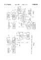
- FIG. 1is a block diagram of a first embodiment of the inventive system for storing recorded information items, such as musical selections, for example, in a master library;
- FIG. 2is a block diagram of the inventive system for retrieving recorded information items from the master library
- FIG. 3is a block diagram of a first embodiment of an analog-to-digital module for converting the analog source music into digital data for processing within the inventive system;
- FIG. 3ais a block diagram of a low pass filter used in the ANDI and the DIAN modules
- FIG. 3bindicates a clock rate caused roll off in the upper frequency range of signals passing through said low pass filter
- FIG. 4is a timing chart for the operation of the analog-to-digital converter of FIG. 3;
- FIG. 5is a block diagram of a command control computer for se in the circuit of FIG. 1;
- FIG. 6is a block diagram of a master storage circuit for se in FIG. 1;
- FIG. 7is a block diagram of a master storage controller circuit used in FIG. 1;
- FIG. 8is a block diagram of a source media for use in FIG. 1;
- FIG. 9is a block diagram of a first embodiment of a digital-to-analog module for converting the digital data processed by the inventive system into an analog form for recording;
- FIG. 10is a timing diagram for the digital-to-analog converter of FIG. 5;
- FIG. 11is a destination controller for directing data taken from the master library to the album sized recording medium
- FIG. 12is a block diagram of an intermediate storage circuit for buffer storing digital data relating to recorded information items which are read out of the master library and prior to its recording on the customized album;
- FIG. 13is a block diagram for a destination medium on which the custom album is recorded
- FIG. 14is a graph illustrating, by best case and worst case examples, a loss of fidelity in a conventional prior art PCM recording
- FIG. 15is a similar graph showing how a second embodiment of the invention improves the fidelity of the PCM signal
- FIG. 16shows the high frequency end of a recorded characteristic curve that illustrates how the second embodiment of the invention improves the recorded fidelity
- FIG. 17is a block diagram of a second embodiment of the analog-to-digital converter
- FIG. 18is a block diagram of a second embodiment of a digit-to-analog converter
- FIG. 19is a graph similar to FIG. 15 showing how the digital-to-analog circuit converts the digital signals back into an analog signal with improved fidelity;
- FIG. 20is a timing chart for the converter of FIG. 18;
- FIG. 21is a block diagram of a destination controller for use in the information retrieving system of FIG. 2;
- FIG. 22is a flow chart for the circuit of FIG. 21, showing the state of the circuit responsive to a request control logic
- FIG. 23is a flow chart for the circuit of FIG. 21, showing the state of the circuit during bus control;
- FIG. 24is a block diagram of a master storage controller for use in connection with the information retrieving circuit of FIG. 21;
- FIG. 25is a flow chart showing the state of the circuit of FIG. 24 in a request for control condition
- FIG. 26is a flow chart showing the state of the circuit of FIG. 24 during bus control
- FIG. 27is a block diagram showing the intermediate buffer storage of FIG. 2;
- FIG. 28is a flow chart showing the control over the random access memory of FIG. 26.
- FIG. 1shows a system which may be used to store or create a master library containing a repertoire of recorded information items, such as musical selections, for example.
- the major parts of this systemare a central controller 40 operating in response to a command control computer 42, a master storage medium 44, a source medium 46, and an analog to digital conversion module 48.
- the master storage medium 44could be a laser disc, or the like. Any suitable source medium 46 may be used such as records, tapes, compact discs, optical tracks, or the like.
- the pertinent playback device at 46has an analog output at 50 which ANDI module 48 converts into digital data.
- the digital datais then transferred over a data input bus 52 and through storage controller 40 to the master storage medium, via a data bus 54.
- the storage of each recorded information item or selectionis at its own individually identified address location in the master storage medium 44. All of this happens in response to control signals transmitted from a microprocessor or mini-computer 42 over control busses 56-60.
- the selections stored in the master storage medium 44are retrieved for assembly as an album which is recorded on any suitable destination medium 62, such as on a tape cassette, for example, or the like.
- the digital data taken from the master storage medium 44are sent over data bus 54, through the master storage controller 40, and bus 65 to an intermediate buffer storage circuit 64.
- an album amount of music(about forty-five minutes) is assembled in the intermediate storage circuit 64, it is sent over a data bus 66 to a digital-to-analog converter module ("DIAN”) 68, from which an analog signal is sent via bus 70 and recorded onto medium 62.
- DIANdigital-to-analog converter module
- the data retrieval circuit(FIG. 2) is controlled by a destination controller 72, which is driven from the microprocessor 42 via data bus 56 and master storage controller 40. Connected to the input/output ports of the destination controller 72 are data request 74 bus, digital-to-analog control commands bus 76, destination medium control bus 78, storage/retrieval address bus 80, and intermediate buffer storage control bus 82.
- an operatorsimply applies any suitable recorded information in the source medium 46 (FIG. 1) by playing a recording, tape, or the like.
- the operatormay place a phonograph record on a turn table and play it back.
- the command control computer 42assigns suitable addresses to each recorded information item that is played back and stored at 44. This address assignment may be done either automatically or in response to operator entered command signals.
- Any suitable printer 83may print out a master list of recorded items and their addresses in the master storage 44. An automatic address assignment and print out is all done in approximately the same manner that a word processor assigns document numbers and prints out documents.
- an operatorconsults the master list and enters the indicated addresses on a keyboard 85 (FIG. 2) associated with the command control computer 42. Responsive thereto, the master storage controller 40 reads stored data out of the library or libraries at master storage 44, where the digital data is that stored under each selected address. That read out data is then stored in the intermediate buffer storage circuit 64, at an address selected by the destination controller 72. After all of the digital data required to record an entire album is read from the master storage circuit 44, the destination control 72, acting responsive to computer 42, causes the intermediate buffer storage circuit 64 to transmits the entire album of data through the digital to analog "DIAN" module 68 for storage on medium 62, such storage being in an analog form.
- the destination control 72acting responsive to computer 42, causes the intermediate buffer storage circuit 64 to transmits the entire album of data through the digital to analog "DIAN" module 68 for storage on medium 62, such storage being in an analog form.
- the intermediate buffer storage memory 64may have a much smaller capacity. Then, the system may operate on a demand and fetch basis. That is, the master storage circuit 44 reads out a burst of data which is put into intermediate buffer storage at 64. In this alternative system, the resulting stored data immediately begins to be read out of buffer 64 for storage at the destination medium 62. As the data is being so read out, the intermediate buffer storage 64 makes repeated demands for more data from the master storage 44. As each demand is made, more data is fetched from the master storage circuit 44, which is used to replenish the data being taken from the intermediate buffer storage and recorded in the destination medium.
- FIGS. 3, 4show the details of a first embodiment of the "ANDI" analog to digital module 48 and of the timing of the module operation.
- This module 48converts the analog information, taken from the source medium 46 (FIG. 1) into the digital data information that is processed and stored on the master storage device 44.
- the analog signal which is taken from a record or tapeenters the module 48 through input port 84 and the input amplifier 86, which sets a uniform input signal level by providing a suitable gain. Also amplifier 86 isolates the input port 84 from the next stage 88 which is a low pass filter that rolls off or drops out the high frequencies.
- the next stageis the sample and hold amplifier 90, which holds a sample of the input signal at a constant level while the analog-to-digital converter 94 is making its conversion.
- a mode input control signalis applied to the sample and hold amplifier 90 to select between the sample mode and the hold mode.
- amplifier 90reads the input signal and stores it inside the amplifier 90.
- the hold modeit holds the previously sampled voltage at a constant level, to prevent the analog-to-digital converter 94 from trying to convert an input signal with a level that is changing.
- the sample and hold amplifier 90has a very high output impedance.
- the analog-to-digital converter 94has a very low input impedance. Therefore, to compensate for this, a buffer stage 96 is coupled between these two devices. Of course, the buffer may not be required if the impedances match.
- the signal which reaches the analog-to-digital converter 94is converted into digital data, such as a 16-bit digital word, for example.
- digital datasuch as a 16-bit digital word
- the analog-to-digital converter 94strobes the digital word into a first-in first-out ("FIFO") buffer memory 98.
- This bufferstores the samples in aligned rows, which may be 1,024 samples long, for example.
- the command control computer 42(FIGS. 1, 2) retrieves the stored data, on a word by word basis.
- the read-out datais transmitted through the digital buffer 100 to the master storage controller 40.
- This buffer storageenables the two systems to operate at speeds that are not synchronized.
- the bandwidthis selected at 99 by sample and filter clock divisor signals sent over data bus 56 and received in the ANDI module 48.
- the timing generator 101 and the clock divider unit 102are the timing generator 101 and the clock divider unit 102.
- the timing generator 101places the sample and hold amplifier 90 in a particular mode and starts the analog-to-digital converter 94.
- the timing generator 101 and the clock divider unit 102are controlled via bus 56, by a signal which is sent under the control of the master microprocessor or minicomputer 42.
- the source clock 104is a 5.64480 MHz crystal oscillator which has an output that is an exact multiple of the industry standard sampling rate. Other frequencies may be used in other systems.
- the divider 102provides a divided sample rate which is equivalent to or any multiple of the industry standard rate.
- the timing generator 101in effect, retimes the clock pulses divided by circuit 102 in order to accommodate circuit delays, such as the finite time required for a signal to transfer from the input of amplifier 86 to the input of sample and hold circuit 90, for example.
- the divided sample clock rate pulse streamis sent from clock divider unit 102 over wire 103 to drive the low pass filter 88.
- clock controlled low pass filter 88switches a capacitor back and forth between its input and an output. Its effect is to start a process whereby the analog signal is divided into a plurality of pulses representing the intelligence in the analog signal.
- the low pass filter 88includes a switched capacitor network 105 driven from clock pulses on wire 103, via divider circuit 106, and clock generator 107.
- the divider circuit 106may be set to divide by 1, 2, or 4.
- the switching circuit 105alternately connects a small capacitor to the input terminal "IN” and the output terminal "OUT".
- This filtermay be low pass filter LTC 1062 made by Linear Technology Corporation of Milpitas, Calif. 95035-7487.
- a small segment of the analog signalis fed to a sample and hold capacitor in circuit 90 where it is held long enough to accumulate a charge that represents the instantaneous amplitude of a generally analog wave shape during that segment.
- the command control computer module 42includes a commercially available computer system 110 which should have multi-user capability. That is, the computer should be able to sort and segregate data into a number of different categories. Each of many clients and copyright owners has a separate record keeping memory to make royalty accounting possible. Thus, as each recorded information item is read out of the master storage, a record company or other person owning the copyright on that particular selection receives an accounting credit.
- the command control computerwas a four-user Maxicom/DL computer with an 85-megabyte, hard disk drive.
- This unithas a general purpose parallel interface card 112 which sends commands and receives responses from commands over the various data buses. Any suitable interface circuit 112 may be provided to integrate this computer into the over all system. In general, these interface circuits meet the SCSI (small computer system interface) standards.
- the master storage circuit 44(FIG. 6) includes any suitable recording device, such as a commercially available twelve or fourteen inch laser read-write device 114 with a removable disc.
- a commercially available twelve or fourteen inch laser read-write device 114 with a removable discOne system used an Alcatel Thomson Gigadisc.
- Datais stored on and retrieved from the disc by the master storage circuit 44 in response to standard industry commands. Both the data and the master storage commands are sent over the data bus 54.
- the master storage controller 40uses custom software with a commercially available 32-bit central processor unit 116 which may be a Motorola MVME-130, for example.
- the source medium 46(FIG. 8) is any suitable commercially available, studio quality, reel-to-reel player, phonograph disk player, cassette player, CD disk player, or any other suitable device 126 that can supply suitable audio output signals, usually analog signals.
- the storage controller 40selects the bandwidth. Then, controller 40 starts the source medium 46 by sending signals over the source medium control bus 58. Once the master storage controller 40 has started the source medium 46, it begins receiving samples which are sent from the ANDI module 48 over the input data bus 52. These samples are forwarded through the bus 52 to the master storage circuit 44 by way of the data bus 54.
- controller 40sets up the destination controller 72 (FIG. 2) by way of the command bus 56.
- the destination controllerbegins a retrieve cycle in order to take data from master storage circuit 44 by way of the master storage data bus 54 and the SCSI interface card 118 (FIG. 7).
- the information that is being received from master storage circuit 64is sent over the data bus 54 to the intermediate buffer storage circuit 64, where it is stored.
- FIGS. 9, 10show details of a first embodiment of the digital-to-analog (DIAN) module 68 and of the timing of the module operations.
- This module 68translates the digital data as it is received from the destination controller circuit 72 (FIG. 2) into the analog information that is required for the destination medium 62.
- the digital-to-analog conversion processstarts with the destination controller circuit 72 setting a clock divider unit 130 in the module of FIG. 9 to operate at the desired output sample rate.
- the command signals that set the sample rateare sent via the command control bus 76.
- the destination controller 72(FIG. 2) starts the destination medium via bus 78.
- the intermediate buffer storage circuit 64continuously sends 16-bit samples to the first-in first-out buffer circuit 132 (FIG. 9), over the data bus 66.
- Timing generator 134Two critical circuits in the digital-to-analog module (FIG. 9) are the timing generator 134 and the clock divider unit 130.
- the timing generatorretimes the divided clock pulses in order to accommodate the circuit delays. For example, there is a circuit delay that is required for a signal to transfer from the FIFO buffer 132 to the converter 142, which the retimed pulse accommodates.
- the master clock 136has a frequency of 5.64480 MHz in this embodiment. This frequency is divided by the clock divider unit 130.
- the destination controller 72sends a divisor control signal to the clock divider unit 130 which is used to divide the master clock pulse repetition rate.
- the destination controlleralso sends a divisor control signal over the command control bus 76 and through circuit 130 to the low pass filter 140, which uses it as a filter clock frequency.
- the output of the low pass filter 140goes through an output buffer 146 in order to drive the destination medium 62 via bus 70.
- the timing generator 134As the sample clock pulse stream is sent to the timing generator 134, it generates and sends a read pulse to the first-in first-out buffer 132. Once this read pulse has been sent, the data is read out of the first-in first-out buffer 132 to the digital-to-analog converter 142. Converter 142 then receives a start command from the timing generator 134, via wire 143, whereupon it ignores all other data on its inputs and converts the digital data word that it receives into an analog output sample. The analog output signal travels through a buffer stage 144 to low pass filter 140, which limits the output frequency response of the system. Because the output sample frequency may be changed for varying destination speeds, the low pass filter 140 may be programmed to vary the roll off frequencies, without requiring a revision of the software.
- FIG. 10shows the timing for the operation of digital to analog converter of FIG. 9. It is thought that this chart is self explanatory.
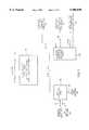
- the details of one embodiment of the destination controller 72are shown in FIG. 11 as including two 32-bit binary counters 150, 152 and a destination control latch 154.
- the destination control processbegins with the master storage controller 40 (FIG. 2) storing, via the command bus 56, a start address in the 32-bit binary counter 150.
- Destination controller 72triggers the digital-to-analog circuit 68 via the bus 76 (FIG. 9). Then, data bytes begin flowing from the master storage circuit 44 (FIG. 2) through the master storage controller 40 to intermediate buffer storage circuit 64.
- the intermediate buffer storage circuit 64(FIG. 12) has a module with a memory which consists of a large RAM array 156 and a storage capacity of ninety-six or more megabytes. Data comes in from the master storage controller 40 (FIG. 2) via the data bus 65 (FIG. 12) and is combined in circuit 158 with a 32-bit storage address received from the destination controlled 72 by way of the storage address bus 80. This combined data is then stored in RAM 156 at the indicated address. Data is retrieved from the RAM 156 in response to an address that is generated in the destination controller 72 and sent over the retrieve address bus 82. Once the address has been latched at circuit 160, data is retrieved from the RAM array 156 and is sent to the DIAN module 68 via the data bus 66.
- the intermediate buffer storage circuit 64receives a data byte, it also sends a strobe signal over part of the data bus 56 to the destination controller 72 (FIG. 2).
- This strobe signalincrements the counter 158 each time that a data byte is stored into intermediate buffer storage circuit 64.
- the new addressis incremented and sent back from the destination controller 72 to intermediate buffer storage circuit 64 via the address bus 80.
- the master storage controller 40has sent all of its data bytes to the intermediate buffer storage, at which time it sends a sample rate divisor to the digital-to-analog module 68 (FIG. 2) via the command bus 56.
- destination controller 72sends a destination medium control start signal over the destination medium control bus 78 (FIG. 11). Assuming that the destination medium is a cassette recorder, it is started in a record mode by this signal. Then, the destination controller circuit 72 sets up the intermediate buffer storage circuit 64 (FIG. 12), starting a retrieve address routine via the command bus 82 and then enables the digital-to-analog module 68. As they are needed, the module 68 sends a data bytes request signal over the data request bus 74 to the intermediate buffer storage circuit 64. Also, destination controller 72 (FIG.
- the master storage controller 40may send a "rewind" or other suitable command via the destination medium control bus 60 to end the recording production.
- the destination medium 62may include any commercially available duplicator, and usually any suitable cassette recorder, such as those sold under the trademarks Infonix, Pentagon, etc . . . .
- the destination medium 62receives its command (regardless of whether they are "start", “stop”, “rewind” etc . . . ) over the destination medium control bus 78. Once it has received its command, the destination medium 62 then records the audio signals which it receives over the destination medium signal bus 70.
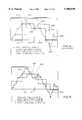
- FIG. 14is a graph which illustrates a problem that the prior art encountered when music is reduced to a pulse code modulation ("PCM”) signal.
- PCMpulse code modulation
- This graphplots time along a horizontal axis and amplitude of sound along a vertical axis.
- a musical signalis shown which is much more complex than a similar voice signal. This complexity occurs because there is an accumulation of musical instruments (trumpets, violins, drums, bells, etc) which together make a much greater variety of sounds than a human voice can make.
- the PCM techniqueoriginated in telephony where the highest frequency level of the transmitted voice signal is about 3500 cps.
- the work which was done for telephonyindicates that the sample rate should be at least twice the highest frequency that is to be encoded (i.e. sample at a frequency which is at least around 7000 cps).
- a sine wavesuitably approximates a voice signal as it is transmitted over a telephone line, since the wave form of the lower frequencies of a single human voice does not depart too far from such a sine wave.
- a sine wavedoes not provide an adequate basis for a study of musical signals, filled with the complex sounds of an orchestra, for example.
- telephonyis interested in a low cost transmission of a signal, with only a sufficient fidelity for (1) an easy understanding of the spoken word and (2) a not too offensive overall sound. In music, a mere understanding is not enough. There is a demand for complete fidelity, at a quality standard which is much higher than the quality which is required for simple speech.
- FIG. 14contains an analog wave form 200 of music which has been arbitrarily drawn to show that a simple sine wave can not represent more than a bare minimum of the available intelligence.
- telephony studies based on sine wavesare not adequate to teach how to encode musical signals. Accordingly, the standard sampling rate at twice the highest frequency is not adequate for music.
- the marks 212, 214indicate the boundaries of a single one of many cyclically recurring time slots which have the conventional relationship wherein sampling must be carried out at twice the highest frequency that is to be reproduced.
- the instantaneous amplitudes of the sample line 216indicate a rough approximation between the analog wave 200 and the sample wave form 216 within the time slot 212, 214. The approximation occurs because the volt/second content of the time slot pulses forming lines 216, 228 generally coincide with the averages of the analog wave form.
- sample wave form 200is displaced slightly relative to the time slot 212, 214 so that the sample period coincides with peak values 220, 222 in the analog wave 200, instead of with some fairly randomly positioned mid-points 224, 226 on the analog wave 200.
- sample wave form 228results.
- a visual comparison of sample wave forms 216, 228quickly establishes that the sample wave 228 is a very poor representation of the analog curve 200.
- wave 216may be called the "best” case and wave form 228 may be called the "worst" case.
- sample errorThe differences between (i.e. the spaces between) the analog waveform 200 and the sample waveforms 216, 228 is known as the "sample error.”
- the assumptionhas to be that the time slots and an analog average will not always coincide with a resulting worst case sampling error (i.e. that the error will be that of sample wave form 228 and not of sample wave form 216). Therefore, audio systems should be designed to provide the best possible results with the worst case wave form 228.
- the sample errorincreases with an increase in the frequency of sound represented by the analog signal. Accordingly, the sample error may be reduced by passing the analog wave 200 through a low pass filter. Or stated another way, if a filter eliminates the peaks 220, 222, 223 the worst case sample wave form 228 becomes very close to the optimum sample wave form 216. However, the analog wave form which is being reproduced has already lost much of its character by the low pass filtering. This low frequency filtering of the analog wave form 200 completely destroys the intelligence represented by the peaks 220, 222, 223. That loss presents a new set of problems for an audio reproduction system which is trying to provide a higher fidelity. Among these problems is a restriction of bandwidth for the recorded signal.
- a sampling systemis run at a very high rate in order to track the analog signal more closely and with greater fidelity than is possible under the industry standard.
- the results of this high speed samplingare fed into a computer which calculates a theoretical wave form, as it would appear at the standard sampling rate, if it follows and approximates the original analog signal with the best cases wave form.
- the PCM signals which are sent to the recorderare based on the theoretical sampling wave form which is calculated and not on the samples which are actually read off the analog signal.
- FIG. 15shows the analog wave form 200 and sampling time slot 212, 214, which are the same as the correspondingly numbered analog wave form and time slot shown in FIG. 14.
- a sampling wave which conforms to this time slot 212, 214has all of the characteristics of a standard sampling wave which may be encoded and later played back on conventionally available reproducing equipment.
- the sampling circuitis driven at a very high rate (such as sixteen times the standard sampling rate).
- the high rate sampling periodsare represented by "X" marks (one of which is 230), each sample having an amplitude which fall on the analog signal.
- a computercalculates the volt/second content of pulses forming the sample wave form 232 or 234 which most closely represents the analog wave 200.
- the best case sample wave form 232 in FIG. 15is drawn to be substantially the same as the best case wave form 216 in FIG. 14; since it is the best case, it does change with the invention.
- the worst case wave form 234 for the inventionis shifted from the best case wave form 216 by the same amount that the prior art worst case wave form 228 is shifted from the best case wave form 216.
- the worst case sample wave form 234is much closer to the best case sample wave form 232, than the worst case prior sample wave form 228 is displaced from the best case sample wave form 216. Accordingly, it is no longer a problem if the sampling tends to coincide with extreme peaks of the analog signal, in the manner that the sampling wave 228 coincides with the extremes of the peaks and valleys of the analog signal 200.
- FIG. 16is a graph which indicates the improved fidelity high frequency end of the spectrum for the inventive recording system, as compared with a prior art recording system, using the standard sampling rate.
- the frequency delivered by a recordingwill rise at some low frequency, have a flat top, and fall off at some high frequency.
- FIG. 16shows that, for the standard system, the fall off is abrupt at about 20K.
- peoplecan not actually hear at these high frequencies, there is a psychological response thereto which greatly enhances the recorded sounds, especially in the "noise" range. (i.e. such things as drums, bells, etc.).
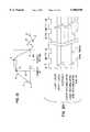
- FIG. 17shows a block diagram of a circuit for practicing this embodiment of the invention.
- a sample clock input 240receives clock pulses at a suitable high frequency repetition rate which enables a closer tracking of the analog signal, as indicated by the X-marks 230 in FIG. 15. It is thought that a sample rate which is sixteen times the normal clock rate might be in order.
- the clock divider circuit 244responds to the clock pulses and provides several output signals.
- the analog signalappears at input terminal 246 and is applied to a gain adjustment circuit 248 which brings all input signals to a standard amplitude. Thereafter, the signals pass through a buffer amplifier 250 which provides isolation.
- Two sample and hold circuits 252, 254are provided to operate alternately since the inventive sample speed is too high for response by components in a single sample and hold circuit having an acceptable level of precision of response.
- the sample and hold circuits 252, 254are alternately enabled under the control of a sequence and selector circuit driven from the clock divider circuit 244.
- the circuits for actually selecting these sample and hold circuitsis represented by the switches 258, 260, 258', 260'.
- the outputs of these sample and hold circuits 252, 254are applied to the input of an analog-to-digital converter 262.
- the clock divider circuit 244applies clock pulses to sequence and selector circuit 256 and to the converter 262 at the high repetition rate of the sample clock 240.
- the pulsesare reshaped by pulse shaper 264.
- the high sample ratemay be sixteen times the standard sample rate.
- the clock dividerpulses a timing generator 266 to inform it of the time conversion, and it groups the high speed samples at the standard rate. For example, at the suggested sixteen-to-one time conversion, clock divider 244 pulses the "first" terminal 268 on the first of each of sixteen sequential clock pulses and pulses the "last" terminal 270 on the sixteenth pulse, immediately followed by a reset pulse 272 on the "reset” terminal. Thus, circuit 266 groups sixteen high speed samples into one standard sample.
- the analog-to-digital converter 262converts each sample pulse in response to a clock pulse transmitted through pulse shaper 264 to the "Go" terminal. After each of the sixteen samples in a group, the converter 262 sends a "done” signal to the timing generator 266.
- the clock divider 244sends a four bit number to the ROM 274 for each of the sixteen samples applied to and encoded by converter 262, to identify each of the sixteen high speed samples in a group as it is then being received.
- This numbercauses the ROM 274 to send a coefficient to an accumulator 276, where it is used as a multiplier.
- the coefficients in the ROMare put there by a programmer who designs the ROM. For example, if all sixteen pulses have the same weight, the multiplier is 1/16 for each high speed sample pulse. On the other hand, if the circuit 276 takes a trend into account, there may be different coefficients for each high speed sample in the group.
- the coefficientsrepresent the area of a triangle. Another coefficient is used to produce the area of a rectangle if the high speed samples have an envelope which is a rectangular curve within the sample area represented by the group of sixteen high speed samples.
- the analog-to-digital converter circuit 262sends each of the digitally encoded pulses which represent the analog signal to the accumulator 276. There, they are multiplied by the coefficient derived from the ROM 274 and then accumulated to bring the sample signals into correspondence with the industry standard sampling rate.
- FIG. 15has been drawn to show sixteen X-marks 230 on the analog curve 200, within the standard sample period 212, 214.
- the converter 262,(FIG. 17) converts each of the high speed samples represented by these X-marks into a pulse code, which is sent to accumulator 276.
- the accumulatorstores the codes of the sixteen samples forming a group corresponding to a standard time slot and computes the pulse code of a hypothetical sample that best represents the analog curve during the standard time slot 212, 214.
- the data latch circuit 278is enabled periodically to gate out the pulse code representing the hypothetical sample of the standard time slot. This code may be recorded directly; or, depending upon system needs, it may be transmitted to a FIFO memory for buffer storage to enable a retiming of the code pulses.
- the timing generatorpulses a "strobe" lead 280 to inform associated equipment that a sample has been completed and is coming to be recorded. That associated equipment responds to the strobe by pulsing the acknowledge bus 282. The circuit is now ready to process the next sample.
- the second embodiment of digital-to-analog module 68is substantially the inverse of the circuit shown in FIG. 17.
- the coefficient ROM 274may play a more important role since the sixteen high speed sample pulses may be given different amplitudes, thereby more closely approximating the true analog curve.
- FIGS. 18-28Details of the system for recovering the analog signal are given in FIGS. 18-28, which relate to the construction of the DIAN module 68 (FIG. 2), the destination controller 72, and the intermediate buffer storage circuit 64.
- the DIAN(FIG. 18) is another embodiment of the DIAN module, which is shown in FIG. 9, and which may compute a more accurate analog curve. More particularly, the digital-to-analog converter circuit ("DIAN") of FIG. 18 is substantially the reverse of analog-to-digital circuit ("ANDI") of FIG. 3.
- DIANdigital-to-analog converter circuit
- ANDIanalog-to-digital circuit
- Each of these DIAN converter circuitsis also individually useful, aside from their use in the inventive system.
- the ANDI circuitcould be used as part of a recorder, and the DIAN could be used in a playback system.
- these circuitsare described herein as being used together in a single system.
- the oversampled output of the digital-to-analog module of FIG. 18almost eliminates the need for an output low-pass filter, since the oversampled output does almost all of the filtration itself, as indicated in FIG. 3b.
- the DIAN actionmakes a very high speed operation possible without requiring a switched capacitor filter. Also, if it should become desirable to change the output speed, say from 16 ⁇ to 32 ⁇ , the DIAN action tends to eliminate a need for low pass filters.
- line-Arepresents the original analog wave form which was the basis of the analog-to-digital conversion in FIG. 3. Therefore, ideally, this exact curve desired at the output of the DIAN module.
- Line-Brepresents a stepped output curve which a standard PCM converter would produce, based on the samples taken at points 1, 2, 3, 4, and 5 in line-A of FIG. 19.
- Line-Crepresents the computed analog output which is produced by the DIAN module of FIG. 18.
- Line-Cis created by computing sixteen samples (each represented by a dot) which are at points that are evenly distributed along segments of a sine wave which are most likely to represent the changes between the successive points 1 and 5.
- the DIANreceives the digital or stepped signal represented by line B; however, it is completely obvious that the analog signal did not have the stepped wave with square corners at 1, 2, 3, 4, 5. There was a relatively smooth curve extending between these successive points.
- a simple sine wavedoes not approximate a continuous flow of an entire analog musical selection in the sense that it approximates a human voice for telephonic communications. However, it is much better than a square wave and for the brief time represented by points 1, 2; 2, 3; . . . 4, 5, it does approximate music.
- segments of a sine waveare superior, as compared to the approximation of the square wave B.
- the circuit in the inventive systemlooks at points 1, 2 on curve B and computes sixteen points (shown by dots on curve C) evenly spaced between the sampled points 1, 2.
- the computercalculates a segment of a sine wave which would most likely fit the change represented by points 1, 2.
- the circuitlooks at the change represented by points 2, 3, and computes sixteen points which are evenly spaced to this next point or which represent a segment of a sine wave which most approximates the change.
- the calculated analog waveis linear between the points 1, 2; 2, 3; etc.
- the segment of the sine wave which was computed for the change between points 1, 2, and the next computations for two segments of a sine wave curve most likely to have occurred between points 3, 4 and 4, 5form the analog curve.
- the DIAN converterdraws a "most probable" curve which fits the leading corners of the successive square wave pulses stored in the intermediate buffer storage circuit 64.
- a wave formmay be computed which is a more faithful duplication of the original analog wave form. Since the computed waveform is smoother than the conventional digital curve, it reduces the demands upon the low pass output filter, thus both improving the performance and reducing the complexity of the circuit.
- the operation of the DIAN module of FIG. 18is coordinated by clock signals which are multiplied by sixteen and applied through timing generator 348.
- This clocking systemis similar to the clocking system that is shown at 244 in FIG. 17.
- the sample datais received from the intermediate buffer storage circuit 64 (FIG. 2), via data bus 66 (FIG. 18), which is the same as bus 66 shown in FIG. 2.
- This sample datais latched in the input latch 352 (FIG. 18) on the first sample clock pulse that is received via wire 76 from the destination controller 72 (FIG. 2).
- subtractor 356subtracts the output signal of the last sample latch 354 from the present signal supplied by the input latch 352.
- the difference resulting from this subtractionis the delta modulation or the change in signal (points 1, 2 or 2, 3 . . . in FIG. 19), which is then latched on the output of the subtractor unit 356.
- This difference or change signalis divided by sixteen at 357 and applied to accumulator 358.
- FIG. 20is a self-explanatory series of time related pulses which show the timing of the circuit of FIG. 18.
- the destination controller 72(FIG. 21) is an alternative embodiment of the destination controller 72 of FIG. 2.
- the destination controller 72(FIG. 21) uses a control processor 370 which may be a micro processor or a minicomputer that controls a plurality of DIAN modules 68, each of which may be in FIGS. 2 or 18.
- Each DIAN modulehas access through a first-in-first-out buffer memory 368 to a byte unstacker 380 which converts the bit transmission stream between serial and parallel streams in order to take data from memory and transmit it over a data bus.
- the control processor 370also drives address generators 372-376 which increment to successively call up the data store in memory and to transmit it through the DIAN modules 68 to the outgoing signal buses.
- the inventive systemis used to record a conventional audio cassette, there are A and B tracks, each with a left and a right channel to give stereo sound.
- the DIAN #1(FIG. 21) provides the left channel for the A track, as indicated on the left-hand edge of FIG. 21 by the notation "A L ".
- the DIAN #2provides the right channel for the A track A R .
- the DIAN #Nprovides the right channel for the B track, B R .
- Another DIAN module(not shown) provides the left channel for the B track. All of these channels correspond to wire 70 in FIG. 2.
- the input signalsarrive at the intermediate buffer storage circuit 64 via wire 65.
- the signal pathis traced from wire 65, through intermediate buffer storage circuit 64, data latch 385, byte unstacker 380, a FIFO memory, a DIAN module, and conductors 70.
- a command to reproduce recorded informationis received over command bus 56, which also appears in FIG. 2.
- This commandis fed into the control processor 370 (FIG. 21), whereupon the control processor 370 sets the appropriate starting addresses for each of the address generators 372-376, associated with the DIAN modules 68. After the addresses are set, processor 370 selects the direction in which the address counts increment in the address generators and thus the directions in which the bytes are read out. This ability to provide a selected one of bidirectional read outs enables the system to playback the recorded information in both the forward and reverse directions.
- the recorded destination mediummay be recorded in either a backward or a forward direction.
- the conventional audio tape cassettehas tracks A and B which are played back while the tape moves in opposite directions.
- DIAN modules #1, 2read out in a forward direction while DIAN module #N (and another not shown) read out in an opposite direction.
- the inventionrecords track A from start-to-finish and track B from finish to start. The consumer plays side A while the tape moves in one direction and then turns over the cassette and plays side B while the tape moves in the opposite direction.
- the inventionmay read bidirectionally out of memory in order to record both tracks on one pass.
- the control processor 370starts the destination medium to moving and enables the operation of appropriate DIAN modules 68. Once a DIAN module is enabled, it requests data from the request control logic 378.
- the request control logic 378determines the priority of and selects between the requesting DIAN modules. Then, logic controller 378 selects the direction in which the bytes are to be% read out of memory by the byte unstacker 380 and requests data from the bus control logic circuit 382. This state is maintained until the "done" signal is returned by bus control logic circuit 382.
- the "done” signaltells the request control logic circuit 378 that all of the data bytes have been read from a RAM (Random Access Memory) in the intermediate buffer storage circuit 64 (FIG. 2), the read out control being accomplished via buses 80 and 82. At this point, the request control logic 378 waits for the "unstack-done" command from byte unstacker 380.
- the byte unstacker 380writes the data readout over buses 80 and 82 through a FIFO memory 368 and into the appropriate DIAN module 68.
- byte-unstacker 380sends an unstack done signal to request control logic 378, thereby indicating a completion of the readout of the recorded information.
- Request control logic 378then counts one address as having been done in the requesting DIAN module. From this address, the address generator may either count up or count down depending on the direction selected by the control processor 370 and given to the address generators 372-376. At this point, the request control logic circuit 376 sends an acknowledge pulse to the requesting DIAN module, which then terminates a cycle.
- This data read out cyclerepeats continuously until the destination medium has been completely recorded. Then, the control processor 370 stops the destination medium by sending a signal over bus 78 and simultaneously inhibits the DIAN modules that were being used. This timing, as described above, is set forth in the flow chart of FIG. 22.
- bus control logic circuit 382When the bus control logic circuit 382 receives a request from request control logic 378, it initiates a read cycle, responsive to signals sent over buses 80 and 82 via the read and output enable lines. Then, logic circuit 382 strobes the line which causes the intermediate buffer storage circuit 64 to read stored information from memory. This state is maintained until the buffer memory storage circuit has terminated its read cycle, which is indicated by a "done" pulse sent from the intermediate buffer storage circuit to bus control logic circuit 382. Bus control logic 382 then releases the read, write, strobe, and output enable lines. A signal is sent to the request control logic circuit 378 to indicate that the cycle is done, the signal being sent via the done line. This state is maintained until the request control logic circuit 378 releases the request line "REQ" extending to bus control logic circuit 382. The sequence of events followed by the bus control logic circuit 382 is set forth in the flow diagram or FIG. 23.
- FIG. 24shows a second embodiment of a master storage controller which serves as item 40 in FIG. 2, and includes intermediate buffer storage circuit 64.
- the master storage controlleris similar to the destination controller of FIG. 21 in that it is controlled by the microprocessor or minicomputer 370 and request control logic 378.
- the logic circuit 378has access to a plurality of master storage devices 386 which fit into the overall circuit at 44 (FIG. 2).
- the byte stacker 390converts between parallel and serial data transmission, taking data from storage and sending it over a line to the intermediate buffer storage. Again, the data may be read out of storage under the control of address generator circuits.
- the recorded information or audio signalsare taken from the master storage devices 386, which may be disks recorded by a laser beam. There may be many such master storage disks for storing information in order to provide greater capacity.
- the audio signal pathmay be traced from the master storage devices through byte stacker 390, data drivers 391, bus 56, and intermediate buffer storage circuit 64 to an output bus 66.
- the command to retrieve datais received via command bus 56 (FIG. 24) and stored in the control processor 370, whereupon it sets the appropriate starting addresses in each of the address generators 372-378 which are individually associated with each master storage device 386. The starting address is relative to the placement of music on the destination medium. Then, the control processor 370 resets all master storage FIFO (first in, first out) buffer memories 388 to be sure that no stray data is in them.
- FIFOfirst in, first out
- control processor 370begins to send retrieve data commands to the master storage units 386.
- a master storage unitbegins to read data, it also latches the data, byte-by-byte, into its associated FIFO buffer memory 388.
- each FIFO buffer memoryreaches its half-full state, it requests service from the request control logic circuit 378.
- the request control logic circuit 378determines priority among the service requesting FIFO devices. Then it sends an identification of the FIFO device with the highest current priority to the byte stacker 390, and also sends a start-to-stack signal.
- the byte-stacker 390reads out data from the FIFO buffers 388 and latches them into its internal data register. After all bytes have been stacked, the byte stacker 390 sends the stack done signal to request control logic circuit 378, to indicate the completion of the readout. Request control logic circuit 378 then sends a request signal REQ to bus control logic circuit 382. This state is maintained until the done signal is returned from bus control logic circuit 382, to indicate to the request control logic circuit 378 that the data bytes have been written into a RAM in intermediate buffer storage via buses 80 and 82.
- request control logic 378increments the storage address counter for the requesting one of the master storage devices 386. This cycle continues until all of the required data is read from the master storage devices.
- the timing for FIG. 24is detailed in the flow chart of FIG. 25.
- FIG. 27is primarily a random access memory (RAM) with peripheral control circuits.
- the recorded information or audio signalsenter at 65 and leave at 66 in the upper left corner of the figure. During the period while the signals are in the intermediate buffer storage circuit 64, they are stored in RAM array 400. The remainder of FIG. 27 is devoted to control circuits.
- bus control logic circuit 382(FIG. 24) receives a request from request control logic circuit 378, it initiates a write to memory cycle by sending write and bus enable signals over via buses 80 and 82. Then, bus control logic 382 pulses the strobe line in bus 82, which causes the intermediate buffer to write into memory. This write state is maintained until the intermediate buffer storage circuit terminates its read cycle which is indicated by a done pulse which is sent to bus control logic circuit 382. Responsive thereto, the bus control logic releases the read, write, strobe and bus enable lines and indicates to request control logic circuit 378 that the cycle is done. This state is maintained until request control logic circuit 378 releases its request line. This sequence of events for the bus control logic circuit 382 is set forth in the flow chart of FIG. 25.
- the intermediate buffer storage circuitincludes a state control circuit 390, a refresh control timer 392, an address decoder 394, address drivers 396, data and control drivers 398, and a large array of RAM chips 400.
- the state control logic circuit 390waits for a command strobe pulse from bus control logic 382 which is transmitted via the data buses. If the command strobe pulse is given and a board select signal is received from the address decoder 394, a particular memory board is enabled in the RAM array 400.
- the state control logic circuit 390then checks for the presence of a valid read or write pulse. If it is a valid read signal, the address received from the address bus is latched and the row address is sent to the addressed RAM in array 400. The addressed row is strobed via the address strobe wire (RAS) and the control decoder and drive circuit 398.
- RASaddress strobe wire
- the control drive circuit 398determines which of four banks of RAM chips is being requested by bus control logic 382, and gives an appropriate RAS signal.
- state control logic circuit 390gives a signal over the MUX line to change the address line drivers to the column address.
- the selected column address line (CAS)is strobed through the control drive circuit 398.
- the control decoders in circuit 398then give the appropriate CAS signal.
- the RAM access timehas passed, the data returning from the RAM array is latched into the data latches 396.
- the done signalis given to the bus control logic 382 that is then requesting the data.
- a refresh cycleis inserted to retain the data in the RAM chips. This also resets timer 392 to prevent a board generated refresh. After the refresh cycle is complete, the refresh timer 394 is reset.
- the command strobeis released, along with all data bus drivers. The circuit has now returned to its idle state.
- control drive circuit 398sends data and a row address to the RAM array 400, along with the row address strobe signal (RAS). Then, control drive circuit 398 sends the column address to the RAM array along with an address strobe (CAS) and waits for a period equal to the write time of the RAM. After completion of the write cycle, the done command is sent to the requesting control logic. A refresh cycle is added to retain the memory. After the refresh cycle is complete, the refresh timer is reset and the command strobe is released, along with all data bus drivers. The circuit returns again to the idle state.
- RASrow address strobe signal
- the refresh control timer 392waits for a predetermined period of time after either a read or write request is received. If no RAM access occurs, the refresh control timer 392 requests the state control logic circuit 390 to issue a refresh cycle signal. The refresh timer maintains a continued storage of the data in the RAM chips.
- a suitable RAM chip for use in this systemis a 1 megabit RAM chip such as that manufactured by the Toshiba Corporation and known as a type TC511000. Because of the high data transfer rate which is possible with this form of multiple master storage devices, a RAM chip access time of 100 nanoseconds or shorter may be used.
- FIG. 28is a flow chart which gives the timing for the intermediate buffer storage circuit of FIG. 27.
Landscapes
- Engineering & Computer Science (AREA)
- General Physics & Mathematics (AREA)
- Business, Economics & Management (AREA)
- Physics & Mathematics (AREA)
- Accounting & Taxation (AREA)
- Multimedia (AREA)
- Strategic Management (AREA)
- General Business, Economics & Management (AREA)
- Theoretical Computer Science (AREA)
- General Engineering & Computer Science (AREA)
- Finance (AREA)
- Signal Processing For Digital Recording And Reproducing (AREA)
- Management Or Editing Of Information On Record Carriers (AREA)
Abstract
Description
Claims (1)
Priority Applications (2)
| Application Number | Priority Date | Filing Date | Title |
|---|---|---|---|
| US08/446,449US5900830A (en) | 1987-01-06 | 1995-05-22 | System for custom recording |
| US09/055,806US6263154B1 (en) | 1987-01-06 | 1998-04-06 | Multiple user recording system |
Applications Claiming Priority (7)
| Application Number | Priority Date | Filing Date | Title |
|---|---|---|---|
| US87487A | 1987-01-06 | 1987-01-06 | |
| US07/133,936US5041921A (en) | 1987-01-06 | 1987-12-17 | System for recording custom albums from a library of pre-recorded items |
| US69229291A | 1991-04-25 | 1991-04-25 | |
| US93288192A | 1992-08-20 | 1992-08-20 | |
| US8840493A | 1993-07-07 | 1993-07-07 | |
| US08/221,084US5418654A (en) | 1987-01-06 | 1994-03-31 | System for recording custom albums from a library of pre-recorded items |
| US08/446,449US5900830A (en) | 1987-01-06 | 1995-05-22 | System for custom recording |
Related Parent Applications (1)
| Application Number | Title | Priority Date | Filing Date |
|---|---|---|---|
| US08/221,084ContinuationUS5418654A (en) | 1987-01-06 | 1994-03-31 | System for recording custom albums from a library of pre-recorded items |
Related Child Applications (1)
| Application Number | Title | Priority Date | Filing Date |
|---|---|---|---|
| US09/055,806ContinuationUS6263154B1 (en) | 1987-01-06 | 1998-04-06 | Multiple user recording system |
Publications (1)
| Publication Number | Publication Date |
|---|---|
| US5900830Atrue US5900830A (en) | 1999-05-04 |
Family
ID=26668256
Family Applications (4)
| Application Number | Title | Priority Date | Filing Date |
|---|---|---|---|
| US07/133,936Expired - LifetimeUS5041921A (en) | 1987-01-06 | 1987-12-17 | System for recording custom albums from a library of pre-recorded items |
| US08/221,084Expired - LifetimeUS5418654A (en) | 1987-01-06 | 1994-03-31 | System for recording custom albums from a library of pre-recorded items |
| US08/446,449Expired - LifetimeUS5900830A (en) | 1987-01-06 | 1995-05-22 | System for custom recording |
| US09/055,806Expired - Fee RelatedUS6263154B1 (en) | 1987-01-06 | 1998-04-06 | Multiple user recording system |
Family Applications Before (2)
| Application Number | Title | Priority Date | Filing Date |
|---|---|---|---|
| US07/133,936Expired - LifetimeUS5041921A (en) | 1987-01-06 | 1987-12-17 | System for recording custom albums from a library of pre-recorded items |
| US08/221,084Expired - LifetimeUS5418654A (en) | 1987-01-06 | 1994-03-31 | System for recording custom albums from a library of pre-recorded items |
Family Applications After (1)
| Application Number | Title | Priority Date | Filing Date |
|---|---|---|---|
| US09/055,806Expired - Fee RelatedUS6263154B1 (en) | 1987-01-06 | 1998-04-06 | Multiple user recording system |
Country Status (6)
| Country | Link |
|---|---|
| US (4) | US5041921A (en) |
| JP (1) | JP3072488B2 (en) |
| CA (1) | CA1327395C (en) |
| DE (1) | DE3800065C2 (en) |
| FR (1) | FR2611299B1 (en) |
| GB (1) | GB2199984B (en) |
Cited By (31)
| Publication number | Priority date | Publication date | Assignee | Title |
|---|---|---|---|---|
| US6078972A (en)* | 1996-11-06 | 2000-06-20 | Nec Corporation | Control system of FIFO memories |
| US6184813B1 (en)* | 1998-11-20 | 2001-02-06 | Legerity, Inc. | Method and apparatus for synchronizing signals |
| US6393430B1 (en)* | 1998-05-08 | 2002-05-21 | Sony Corporation | Method and system for automatically recording music data files by using the hard drive of a personal computer as an intermediate storage medium |
| US20020120936A1 (en)* | 2000-10-10 | 2002-08-29 | Del Beccaro David J. | System and method for receiving broadcast audio/video works and for enabling a consumer to purchase the received audio/video works |
| US6446080B1 (en)* | 1998-05-08 | 2002-09-03 | Sony Corporation | Method for creating, modifying, and playing a custom playlist, saved as a virtual CD, to be played by a digital audio/visual actuator device |
| WO2002071617A1 (en)* | 2001-03-03 | 2002-09-12 | Optimum Power Technology, L.P. | Apparatus and method for adjusting filter frequency in relation to sampling frequency |
| US6496802B1 (en) | 2000-01-07 | 2002-12-17 | Mp3.Com, Inc. | System and method for providing access to electronic works |
| US6879963B1 (en) | 2000-04-12 | 2005-04-12 | Music Choice | Cross channel delivery system and method |
| US20060075132A1 (en)* | 2004-09-15 | 2006-04-06 | Nokia Corporation | Compressing, filtering, and transmitting of protocol messages via a protocol-aware intermediary node |
| US7028082B1 (en) | 2001-03-08 | 2006-04-11 | Music Choice | Personalized audio system and method |
| US7076561B1 (en) | 2000-03-08 | 2006-07-11 | Music Choice | Personalized audio system and method |
| US20060184431A1 (en)* | 2000-04-12 | 2006-08-17 | Music Choice | Media content delivery systems and methods |
| US20060288082A1 (en)* | 2005-06-15 | 2006-12-21 | Music Choice | Systems and methods for facilitating the acquisition of content |
| US7158169B1 (en) | 2003-03-07 | 2007-01-02 | Music Choice | Method and system for displaying content while reducing burn-in of a display |
| US7240143B1 (en) | 2003-06-06 | 2007-07-03 | Broadbus Technologies, Inc. | Data access and address translation for retrieval of data amongst multiple interconnected access nodes |
| US20070219876A1 (en)* | 2006-03-15 | 2007-09-20 | Digital River, Inc. | Physical On Demand Testing With Version Support |
| US7275256B1 (en) | 2001-08-28 | 2007-09-25 | Music Choice | System and method for providing an interactive, visual complement to an audio program |
| US20070234353A1 (en)* | 2006-01-31 | 2007-10-04 | Digital River, Inc. | Physical on Demand |
| US20070294099A1 (en)* | 2006-03-31 | 2007-12-20 | Digital River, Inc. | Physical On Demand Product Creation System and Method |
| US7325043B1 (en) | 2000-03-08 | 2008-01-29 | Music Choice | System and method for providing a personalized media service |
| US20080059724A1 (en)* | 2003-06-06 | 2008-03-06 | Stifter Francis J Jr | Content distribution and switching amongst data streams |
| US20090164652A1 (en)* | 2007-12-21 | 2009-06-25 | General Instrument Corporation | Methods and System for Processing Time-Based Content |
| US7617295B1 (en) | 2002-03-18 | 2009-11-10 | Music Choice | Systems and methods for providing a broadcast entertainment service and an on-demand entertainment service |
| US7626609B1 (en) | 2003-03-07 | 2009-12-01 | Music Choice | Method and system for displaying content while reducing burn-in of a display |
| US7783722B1 (en) | 2000-03-08 | 2010-08-24 | Music Choice | Personalized audio system and method |
| US7856485B2 (en) | 2000-03-08 | 2010-12-21 | Music Choice | Systems and methods for providing customized media channels |
| US8166133B1 (en) | 2000-03-08 | 2012-04-24 | Music Choice | Systems and methods for providing a broadcast entertainment service and an on-demand entertainment service |
| US8463780B1 (en) | 2000-03-08 | 2013-06-11 | Music Choice | System and method for providing a personalized media service |
| US9456243B1 (en) | 2003-06-06 | 2016-09-27 | Arris Enterprises, Inc. | Methods and apparatus for processing time-based content |
| US10219027B1 (en) | 2014-10-24 | 2019-02-26 | Music Choice | System for providing music content to a user |
| US10390093B1 (en) | 2012-04-26 | 2019-08-20 | Music Choice | Automatic on-demand navigation based on meta-data broadcast with media content |
Families Citing this family (126)
| Publication number | Priority date | Publication date | Assignee | Title |
|---|---|---|---|---|
| US5021893A (en)* | 1987-12-17 | 1991-06-04 | Duplitronics, Inc. | High speed tape duplicating machine |
| US5365381A (en)* | 1987-01-06 | 1994-11-15 | Magic Music Cassette Company | High speed recorded information duplicating equipment |
| CA1302570C (en)* | 1988-09-20 | 1992-06-02 | Thomas P. Crean | Automated video cassette recording and dispensing machine |
| DE3921942A1 (en)* | 1989-07-04 | 1991-01-17 | Grundig Emv | CIRCUIT ARRANGEMENT FOR REVISING A SPOKEN TEXT STORED IN A MAGNETIC TAPE AND / OR SEMICONDUCTOR MEMORY |
| KR970010517B1 (en)* | 1989-07-31 | 1997-06-26 | Lg Electronics Inc | Recording and reproducing apparatus and method using dat memory function |
| NL9001039A (en)* | 1990-05-01 | 1991-12-02 | Philips Nv | DEVICE FOR OBTAINING PRE-PLAYED DIGITAL MUSIC CASSETTES. |
| US5848398A (en)* | 1990-06-15 | 1998-12-08 | Arachnid, Inc. | System for managing a plurality of computer jukeboxes |
| US6970834B2 (en)* | 1990-06-15 | 2005-11-29 | Arachnid, Inc. | Advertisement downloading computer jukebox |
| US20010023403A1 (en)* | 1990-06-15 | 2001-09-20 | Martin John R. | Computer jukebox and jukebox network |
| US5355302A (en) | 1990-06-15 | 1994-10-11 | Arachnid, Inc. | System for managing a plurality of computer jukeboxes |
| US5781889A (en)* | 1990-06-15 | 1998-07-14 | Martin; John R. | Computer jukebox and jukebox network |
| IT1243715B (en)* | 1990-08-31 | 1994-06-21 | Bernardino Bernardini | ELECTRONIC DEVICE FOR THE FAST DUPLICATION OF MAGNETIC TAPES |
| US5963916A (en)* | 1990-09-13 | 1999-10-05 | Intouch Group, Inc. | Network apparatus and method for preview of music products and compilation of market data |
| WO1992007360A1 (en)* | 1990-10-10 | 1992-04-30 | Mario Moro | A recording medium library management system |
| CA2068414C (en)* | 1990-10-24 | 1998-07-21 | David W. Stebbings | Method and apparatus for high speed duplication of audio or digital signals |
| KR960005404B1 (en)* | 1990-12-31 | 1996-04-24 | 삼성전자주식회사 | Program copy method of double deck VCR |
| US5253275A (en) | 1991-01-07 | 1993-10-12 | H. Lee Browne | Audio and video transmission and receiving system |
| US5272627A (en)* | 1991-03-27 | 1993-12-21 | Gulton Industries, Inc. | Data converter for CT data acquisition system |
| US20080228517A1 (en)* | 1992-03-06 | 2008-09-18 | Martin John R | Computer jukebox and jukebox network |
| US5418713A (en)* | 1993-08-05 | 1995-05-23 | Allen; Richard | Apparatus and method for an on demand data delivery system for the preview, selection, retrieval and reproduction at a remote location of previously recorded or programmed materials |
| DE4435450A1 (en)* | 1993-10-04 | 1995-04-06 | Matsushita Electric Industrial Co Ltd | Liquid crystal unit and projection display which uses a liquid crystal unit |
| FR2714760B1 (en)* | 1993-12-30 | 1996-02-02 | Thomson Consumer Electronics | Information recording, storage and reading system. |
| US5590282A (en)* | 1994-07-11 | 1996-12-31 | Clynes; Manfred | Remote access server using files containing generic and specific music data for generating customized music on demand |
| US7424731B1 (en) | 1994-10-12 | 2008-09-09 | Touchtunes Music Corporation | Home digital audiovisual information recording and playback system |
| US7188352B2 (en) | 1995-07-11 | 2007-03-06 | Touchtunes Music Corporation | Intelligent digital audiovisual playback system |
| US8661477B2 (en) | 1994-10-12 | 2014-02-25 | Touchtunes Music Corporation | System for distributing and selecting audio and video information and method implemented by said system |
| EP0786121B1 (en) | 1994-10-12 | 2000-01-12 | Touchtunes Music Corporation | Intelligent digital audiovisual playback system |
| US5793980A (en) | 1994-11-30 | 1998-08-11 | Realnetworks, Inc. | Audio-on-demand communication system |
| US7349976B1 (en) | 1994-11-30 | 2008-03-25 | Realnetworks, Inc. | Audio-on-demand communication system |
| DE19539172C2 (en)* | 1995-03-13 | 1998-06-18 | Nsm Ag | Multimedia box |
| WO1996042074A2 (en)* | 1995-06-09 | 1996-12-27 | Peter Josef Szauder | Information carrier vending machine |
| MY121607A (en)* | 1995-07-10 | 2006-02-28 | Hyundai Curitel Inc | Grid moving method of object image and apparatus using the same and compaction/motion estimation method using the same and apparatus thereof |
| JP3541535B2 (en)* | 1995-11-27 | 2004-07-14 | ソニー株式会社 | Recording device, recording / reproducing device |
| US5726909A (en)* | 1995-12-08 | 1998-03-10 | Krikorian; Thomas M. | Continuous play background music system |
| ITMI960289A1 (en)* | 1996-02-15 | 1997-08-15 | Giacomo Ghisolfi | ELECTRONIC-TELEMATIC-MECHANICAL SYSTEM FOR THE SALE OF LITERARY WORKS FOR AUDIO FOR VIDEO PRODUCED AT THE TIME OF PURCHASE |
| AU2335897A (en)* | 1996-03-21 | 1997-10-10 | Maximum Video Systems, Inc. | High speed video digital versatile disk distribution and manufacturing system |
| NL1003587C2 (en)* | 1996-07-15 | 1998-01-21 | Carel Christiaan Van Helsdinge | Recording station for writing data or music to blank compact disc |
| US5909638A (en)* | 1996-08-06 | 1999-06-01 | Maximum Video Systems, Inc. | High speed video distribution and manufacturing system |
| US5740134A (en) | 1996-08-13 | 1998-04-14 | Peterson; Tim | Musical CD creation unit |
| FR2753868A1 (en) | 1996-09-25 | 1998-03-27 | Technical Maintenance Corp | METHOD FOR SELECTING A RECORDING ON AN AUDIOVISUAL DIGITAL REPRODUCTION SYSTEM AND SYSTEM FOR IMPLEMENTING THE METHOD |
| US5740146A (en)* | 1996-10-22 | 1998-04-14 | Disney Enterprises, Inc. | Method and apparatus for reducing noise using a plurality of recording copies |
| US5959944A (en)* | 1996-11-07 | 1999-09-28 | The Music Connection Corporation | System and method for production of customized compact discs on demand |
| US6011758A (en)* | 1996-11-07 | 2000-01-04 | The Music Connection | System and method for production of compact discs on demand |
| WO1998048363A1 (en)* | 1997-04-22 | 1998-10-29 | Bandai Holding Corporation | Custom information delivery system |
| JP3552474B2 (en)* | 1997-07-06 | 2004-08-11 | 株式会社ケンウッド | Recording medium title input device |
| US7574727B2 (en) | 1997-07-23 | 2009-08-11 | Touchtunes Music Corporation | Intelligent digital audiovisual playback system |
| US6223348B1 (en)* | 1997-09-03 | 2001-04-24 | Universal Electronics Inc. | Universal remote control system |
| FR2769165B1 (en) | 1997-09-26 | 2002-11-29 | Technical Maintenance Corp | WIRELESS SYSTEM WITH DIGITAL TRANSMISSION FOR SPEAKERS |
| JPH11185381A (en)* | 1997-10-16 | 1999-07-09 | Shoichi Iida | System and method for purchasing personal recording medium and recording medium recording personal recording medium purchasing program |
| US5900608A (en)* | 1997-10-16 | 1999-05-04 | Iida; Takahito | Method of purchasing personal recording media, system for purchasing personal recording media, and media recorded with personal recording media purchasing program |
| US6942143B1 (en) | 1997-10-16 | 2005-09-13 | Dentsu, Inc. | System and method for accessing broadcast media in data communication with a broadcast receiving device |
| US6766946B2 (en) | 1997-10-16 | 2004-07-27 | Dentsu, Inc. | System for granting permission of user's personal information to third party |
| US6209787B1 (en) | 1997-10-16 | 2001-04-03 | Takahito Iida | Global access system of multi-media related information |
| DE19757129A1 (en)* | 1997-12-20 | 1999-06-24 | Stefan Kneller | Arrangement for prerecording data medium with music items or video clips |
| FR2781582B1 (en) | 1998-07-21 | 2001-01-12 | Technical Maintenance Corp | SYSTEM FOR DOWNLOADING OBJECTS OR FILES FOR SOFTWARE UPDATE |
| US8028318B2 (en) | 1999-07-21 | 2011-09-27 | Touchtunes Music Corporation | Remote control unit for activating and deactivating means for payment and for displaying payment status |
| FR2781591B1 (en) | 1998-07-22 | 2000-09-22 | Technical Maintenance Corp | AUDIOVISUAL REPRODUCTION SYSTEM |
| FR2781593B1 (en) | 1998-07-22 | 2001-01-12 | Technical Maintenance Corp | REMOTE CONTROL FOR INTELLIGENT DIGITAL AUDIOVISUAL REPRODUCTION SYSTEM |
| US6288719B1 (en) | 1998-10-26 | 2001-09-11 | Eastman Kodak Company | System and method of constructing a photo album |
| FR2781580B1 (en) | 1998-07-22 | 2000-09-22 | Technical Maintenance Corp | SOUND CONTROL CIRCUIT FOR INTELLIGENT DIGITAL AUDIOVISUAL REPRODUCTION SYSTEM |
| US6434579B1 (en) | 1998-08-19 | 2002-08-13 | Eastman Kodak Company | System and method of constructing a photo album |
| US6123362A (en)* | 1998-10-26 | 2000-09-26 | Eastman Kodak Company | System and method of constructing a photo collage |
| AU5591299A (en)* | 1998-07-31 | 2000-02-21 | Benjamin Filmalter Grobler | Data vending system |
| US6606398B2 (en)* | 1998-09-30 | 2003-08-12 | Intel Corporation | Automatic cataloging of people in digital photographs |
| US6389181B2 (en) | 1998-11-25 | 2002-05-14 | Eastman Kodak Company | Photocollage generation and modification using image recognition |
| US6396963B2 (en)* | 1998-12-29 | 2002-05-28 | Eastman Kodak Company | Photocollage generation and modification |
| US6690843B1 (en) | 1998-12-29 | 2004-02-10 | Eastman Kodak Company | System and method of constructing a photo album |
| US6362900B1 (en)* | 1998-12-30 | 2002-03-26 | Eastman Kodak Company | System and method of constructing a photo album |
| US8726330B2 (en) | 1999-02-22 | 2014-05-13 | Touchtunes Music Corporation | Intelligent digital audiovisual playback system |
| JP2000251381A (en)* | 1999-02-25 | 2000-09-14 | Sony Corp | Disk dubbing system |
| KR100575538B1 (en)* | 1999-07-14 | 2006-05-03 | 엘지전자 주식회사 | Audio data converter and data transmission method therefrom |
| FR2796482B1 (en) | 1999-07-16 | 2002-09-06 | Touchtunes Music Corp | REMOTE MANAGEMENT SYSTEM FOR AT LEAST ONE AUDIOVISUAL INFORMATION REPRODUCING DEVICE |
| US7657910B1 (en) | 1999-07-26 | 2010-02-02 | E-Cast Inc. | Distributed electronic entertainment method and apparatus |
| JP4135287B2 (en)* | 2000-02-01 | 2008-08-20 | ソニー株式会社 | RECORDING / REPRODUCING DEVICE, PORTABLE DEVICE, DATA TRANSFER SYSTEM, DATA TRANSFER METHOD, DATA REPRODUCING METHOD, DATA TRANSFER AND REPRODUCING METHOD |
| FR2805377B1 (en) | 2000-02-23 | 2003-09-12 | Touchtunes Music Corp | EARLY ORDERING PROCESS FOR A SELECTION, DIGITAL SYSTEM AND JUKE-BOX FOR IMPLEMENTING THE METHOD |
| FR2805060B1 (en) | 2000-02-16 | 2005-04-08 | Touchtunes Music Corp | METHOD FOR RECEIVING FILES DURING DOWNLOAD |
| FR2805072B1 (en) | 2000-02-16 | 2002-04-05 | Touchtunes Music Corp | METHOD FOR ADJUSTING THE SOUND VOLUME OF A DIGITAL SOUND RECORDING |
| US6560577B1 (en)* | 2000-03-21 | 2003-05-06 | Intel Corporation | Process for encoding audio from an analog medium into a compressed digital format using attribute information and silence detection |
| GB2361129A (en)* | 2000-04-05 | 2001-10-10 | Sony Uk Ltd | Creating a database of audio/video productions |
| FR2808906B1 (en) | 2000-05-10 | 2005-02-11 | Touchtunes Music Corp | DEVICE AND METHOD FOR REMOTELY MANAGING A NETWORK OF AUDIOVISUAL INFORMATION REPRODUCTION SYSTEMS |
| FR2811175B1 (en)* | 2000-06-29 | 2002-12-27 | Touchtunes Music Corp | AUDIOVISUAL INFORMATION DISTRIBUTION METHOD AND AUDIOVISUAL INFORMATION DISTRIBUTION SYSTEM |
| FR2811114B1 (en) | 2000-06-29 | 2002-12-27 | Touchtunes Music Corp | DEVICE AND METHOD FOR COMMUNICATION BETWEEN A SYSTEM FOR REPRODUCING AUDIOVISUAL INFORMATION AND AN ELECTRONIC ENTERTAINMENT MACHINE |
| US6498937B1 (en) | 2000-07-14 | 2002-12-24 | Trw Inc. | Asymmetric bandwidth wireless communication techniques |
| JP4214665B2 (en)* | 2000-07-25 | 2009-01-28 | ソニー株式会社 | Playback device |
| JP4304888B2 (en)* | 2000-09-04 | 2009-07-29 | ソニー株式会社 | Recording medium, editing apparatus and editing method |
| FR2814085B1 (en) | 2000-09-15 | 2005-02-11 | Touchtunes Music Corp | ENTERTAINMENT METHOD BASED ON MULTIPLE CHOICE COMPETITION GAMES |
| JP4555454B2 (en)* | 2000-11-21 | 2010-09-29 | 富士通株式会社 | Data playback device |
| US6520159B2 (en)* | 2001-03-26 | 2003-02-18 | General Motors Corporation | Engine converter misfire protection method and apparatus |
| US7177589B1 (en) | 2001-12-07 | 2007-02-13 | William H Lynch | Satellite entertainment receiver system |
| US8332895B2 (en) | 2002-09-16 | 2012-12-11 | Touchtunes Music Corporation | Digital downloading jukebox system with user-tailored music management, communications, and other tools |
| US10373420B2 (en) | 2002-09-16 | 2019-08-06 | Touchtunes Music Corporation | Digital downloading jukebox with enhanced communication features |
| US8584175B2 (en) | 2002-09-16 | 2013-11-12 | Touchtunes Music Corporation | Digital downloading jukebox system with user-tailored music management, communications, and other tools |
| US11029823B2 (en) | 2002-09-16 | 2021-06-08 | Touchtunes Music Corporation | Jukebox with customizable avatar |
| US9646339B2 (en) | 2002-09-16 | 2017-05-09 | Touchtunes Music Corporation | Digital downloading jukebox system with central and local music servers |
| US8103589B2 (en) | 2002-09-16 | 2012-01-24 | Touchtunes Music Corporation | Digital downloading jukebox system with central and local music servers |
| US8151304B2 (en) | 2002-09-16 | 2012-04-03 | Touchtunes Music Corporation | Digital downloading jukebox system with user-tailored music management, communications, and other tools |
| US7822687B2 (en) | 2002-09-16 | 2010-10-26 | Francois Brillon | Jukebox with customizable avatar |
| US12100258B2 (en) | 2002-09-16 | 2024-09-24 | Touchtunes Music Company, Llc | Digital downloading jukebox with enhanced communication features |
| US20040162633A1 (en)* | 2003-02-19 | 2004-08-19 | Sheldon Kraft | Interactive vending apparatus and method for dispensing and ordering digital media |
| US7216178B2 (en) | 2003-04-04 | 2007-05-08 | Gibson Guitar Corp. | System and method for distributing music to customers over the internet using uniquely identified proprietary devices |
| US7249147B2 (en) | 2003-04-04 | 2007-07-24 | Gibson Guitar Corp. | Combination compact disc recorder and player system |
| US20050234818A1 (en)* | 2004-04-15 | 2005-10-20 | Charles Marshall | Automated on-demand online media manufacturing and fulfillment system |
| US20050234783A1 (en)* | 2004-04-15 | 2005-10-20 | Charles Marshall | Business method for on-demand product manufacturing and fulfillment system |
| US7711835B2 (en) | 2004-09-30 | 2010-05-04 | Citrix Systems, Inc. | Method and apparatus for reducing disclosure of proprietary data in a networked environment |
| US8099482B2 (en)* | 2004-10-01 | 2012-01-17 | E-Cast Inc. | Prioritized content download for an entertainment device |
| US9330529B2 (en) | 2007-01-17 | 2016-05-03 | Touchtunes Music Corporation | Game terminal configured for interaction with jukebox device systems including same, and/or associated methods |
| US9171419B2 (en) | 2007-01-17 | 2015-10-27 | Touchtunes Music Corporation | Coin operated entertainment system |
| US20080228507A1 (en)* | 2007-03-14 | 2008-09-18 | Paul Larue | Retail publishing system, method, program, and apparatus |
| US9953481B2 (en) | 2007-03-26 | 2018-04-24 | Touchtunes Music Corporation | Jukebox with associated video server |
| US10290006B2 (en) | 2008-08-15 | 2019-05-14 | Touchtunes Music Corporation | Digital signage and gaming services to comply with federal and state alcohol and beverage laws and regulations |
| US8332887B2 (en) | 2008-01-10 | 2012-12-11 | Touchtunes Music Corporation | System and/or methods for distributing advertisements from a central advertisement network to a peripheral device via a local advertisement server |
| US8849435B2 (en) | 2008-07-09 | 2014-09-30 | Touchtunes Music Corporation | Digital downloading jukebox with revenue-enhancing features |
| EP2406737A1 (en)* | 2009-03-10 | 2012-01-18 | IMS Software Services, Ltd. | Systems and methods for address intelligence |
| US10719149B2 (en) | 2009-03-18 | 2020-07-21 | Touchtunes Music Corporation | Digital jukebox device with improved user interfaces, and associated methods |
| US9292166B2 (en) | 2009-03-18 | 2016-03-22 | Touchtunes Music Corporation | Digital jukebox device with improved karaoke-related user interfaces, and associated methods |
| US10564804B2 (en) | 2009-03-18 | 2020-02-18 | Touchtunes Music Corporation | Digital jukebox device with improved user interfaces, and associated methods |
| US12112093B2 (en) | 2009-03-18 | 2024-10-08 | Touchtunes Music Company, Llc | Entertainment server and associated social networking services |
| EP2409273A4 (en) | 2009-03-18 | 2016-05-11 | Touchtunes Music Corp | ENTERTAINMENT SERVER AND RELATED SOCIAL NETWORK SERVICES |
| US8185445B1 (en) | 2009-09-09 | 2012-05-22 | Dopa Music Ltd. | Method for providing background music |
| CN105354940A (en) | 2010-01-26 | 2016-02-24 | 踏途音乐公司 | Digital jukebox device with improved user interfaces, and associated methods |
| USD646667S1 (en) | 2010-04-20 | 2011-10-11 | Donegain Douglas T | Portable audio converter |
| GB2522772B (en) | 2011-09-18 | 2016-01-13 | Touchtunes Music Corp | Digital jukebox device with karaoke and/or photo booth features, and associated methods |
| US11151224B2 (en) | 2012-01-09 | 2021-10-19 | Touchtunes Music Corporation | Systems and/or methods for monitoring audio inputs to jukebox devices |
| WO2015070070A1 (en) | 2013-11-07 | 2015-05-14 | Touchtunes Music Corporation | Techniques for generating electronic menu graphical user interface layouts for use in connection with electronic devices |
| JP6777545B2 (en) | 2014-03-25 | 2020-10-28 | タッチチューンズ ミュージック コーポレイションTouchtunes Music Corporation | Digital jukebox devices with an improved user interface and related methods |
| US9967044B1 (en) | 2016-07-25 | 2018-05-08 | Duwayne Morris Gray | Portable music studio |
Citations (27)
| Publication number | Priority date | Publication date | Assignee | Title |
|---|---|---|---|---|
| US3689879A (en)* | 1971-05-18 | 1972-09-05 | Baxter Laboratories Inc | Conservation of transient pulses in analog to digital conversion |
| JPS5050626A (en)* | 1973-09-07 | 1975-05-07 | ||
| US4227226A (en)* | 1977-11-28 | 1980-10-07 | Matsushita Electric Industrial Co., Inc. | Cassette tape player |
| US4229770A (en)* | 1978-02-10 | 1980-10-21 | Sony Corporation | Method of recording on a magnetic tape which is attached to a card |
| GB1581966A (en)* | 1977-02-18 | 1980-12-31 | Sheehan D L | Selection control system for recording tape cartridges |
| US4320486A (en)* | 1980-01-11 | 1982-03-16 | Advanced Integrated Design, Incorporated | Transferring information signals from a first to a second recording medium |
| US4348754A (en)* | 1980-05-15 | 1982-09-07 | Ampex Corporation | Digital delay for high quality audio use |
| US4355338A (en)* | 1979-02-13 | 1982-10-19 | Nippon Columbia K.K. | Duplicator |
| GB2103868A (en)* | 1981-07-24 | 1983-02-23 | Sumitomo Electric Industries | Magnet wires |
| US4375658A (en)* | 1981-01-14 | 1983-03-01 | Verbatim Corporation | Cleaning disk |
| JPS58130414A (en)* | 1982-01-28 | 1983-08-03 | Sony Corp | Recording and reproducing system |
| US4410917A (en)* | 1981-09-14 | 1983-10-18 | Accurate Sound Corporation | Method of and apparatus for recording information from a master medium onto a slave medium employing digital techniques |
| GB2137401A (en)* | 1983-03-10 | 1984-10-03 | Mermaid Distributors | Apparatus for and a method of vending software |
| US4528643A (en)* | 1983-01-10 | 1985-07-09 | Fpdc, Inc. | System for reproducing information in material objects at a point of sale location |
| US4620158A (en)* | 1984-06-20 | 1986-10-28 | Pioneer Electronic Corp. | PCM signal demodulating circuit |
| US4654799A (en)* | 1984-05-18 | 1987-03-31 | Brother Kogyo Kabushiki Kaisha | Software vending system |
| US4703465A (en)* | 1985-12-04 | 1987-10-27 | 1K Entertainment Center Ltd. | Method and apparatus for producing an audio magnetic tape recording from a preselected music library |
| US4707750A (en)* | 1985-02-20 | 1987-11-17 | Media Systems Technology, Inc. | Automatic sequencer for a flexible disk loader/copier |
| US4763207A (en)* | 1985-10-15 | 1988-08-09 | R. R. Donnelley & Sons Company | Digital method and system for reproducing analog data |
| US4766581A (en)* | 1984-08-07 | 1988-08-23 | Justin Korn | Information retrieval system and method using independent user stations |
| US4786983A (en)* | 1981-07-13 | 1988-11-22 | Massari B | System for recording one's own voice on tapes already recorded with musical accompaniments |
| US4811325A (en)* | 1987-10-15 | 1989-03-07 | Personics Corporation | High-speed reproduction facility for audio programs |
| US4835682A (en)* | 1982-09-30 | 1989-05-30 | Tokyo Shibaura Denki Kabushiki Kaisha | Computer system for preventing copying of program from a storage medium by modifying the program using a unique key |
| US4855743A (en)* | 1987-12-09 | 1989-08-08 | Texas Instruments Incorporated | Analog interface system |
| US4899230A (en)* | 1987-12-22 | 1990-02-06 | Idb Corporation | Taped data copying utilizing multiple addressable memories |
| US4958640A (en)* | 1988-12-23 | 1990-09-25 | Spacelabs, Inc. | Method and apparatus for correlating the display of information contained in two information signals |
| US5460038A (en)* | 1992-01-28 | 1995-10-24 | Curtin Matheson Scientific, Inc. | Acoustic displacement flow meter |
Family Cites Families (11)
| Publication number | Priority date | Publication date | Assignee | Title |
|---|---|---|---|---|
| DE2614745B2 (en)* | 1976-04-06 | 1978-05-11 | Teldec Telefunken-Decca-Schallplatten Gmbh, 2000 Hamburg | Device for copying a magnetic tape recording running on a parent machine for the purpose of producing daughter tapes |
| US4227220A (en)* | 1977-05-02 | 1980-10-07 | Hill Brown | Tape recording system |
| US4224983A (en)* | 1978-02-02 | 1980-09-30 | General Atomic Company | Heat exchange apparatus for a reactor |
| US4381522A (en)* | 1980-12-01 | 1983-04-26 | Adams-Russell Co., Inc. | Selective viewing |
| US4375655A (en)* | 1981-01-02 | 1983-03-01 | Memory Control Technology Corporation | Universal digital data copying system |
| IT8122891A0 (en)* | 1981-07-13 | 1981-07-13 | Massari B | SYSTEM FOR THE PRODUCTION OF PERSONALIZED MUSIC TAPE AND VIDEO TAPE. |
| US4682248A (en)* | 1983-04-19 | 1987-07-21 | Compusonics Video Corporation | Audio and video digital recording and playback system |
| JPS6050626A (en)* | 1983-08-29 | 1985-03-20 | Olympus Optical Co Ltd | Duplicator |
| JPS62202332A (en)* | 1986-02-28 | 1987-09-07 | Sony Corp | Audio signal dubbing equipment |
| US5021893A (en) | 1987-12-17 | 1991-06-04 | Duplitronics, Inc. | High speed tape duplicating machine |
| CA1301313C (en)* | 1987-02-20 | 1992-05-19 | Lorne A. Parker | Method and apparatus for producing an audio magnetic tape recording at high speed from a preselected music library |
- 1987
- 1987-12-17USUS07/133,936patent/US5041921A/ennot_activeExpired - Lifetime
- 1988
- 1988-01-05FRFR8800075Apatent/FR2611299B1/ennot_activeExpired - Fee Related
- 1988-01-05DEDE3800065Apatent/DE3800065C2/ennot_activeExpired - Fee Related
- 1988-01-05CACA000555902Apatent/CA1327395C/ennot_activeExpired - Fee Related
- 1988-01-06GBGB8800226Apatent/GB2199984B/ennot_activeExpired - Fee Related
- 1988-01-06JPJP63000449Apatent/JP3072488B2/ennot_activeExpired - Fee Related
- 1994
- 1994-03-31USUS08/221,084patent/US5418654A/ennot_activeExpired - Lifetime
- 1995
- 1995-05-22USUS08/446,449patent/US5900830A/ennot_activeExpired - Lifetime
- 1998
- 1998-04-06USUS09/055,806patent/US6263154B1/ennot_activeExpired - Fee Related
Patent Citations (28)
| Publication number | Priority date | Publication date | Assignee | Title |
|---|---|---|---|---|
| US3689879A (en)* | 1971-05-18 | 1972-09-05 | Baxter Laboratories Inc | Conservation of transient pulses in analog to digital conversion |
| JPS5050626A (en)* | 1973-09-07 | 1975-05-07 | ||
| GB1581966A (en)* | 1977-02-18 | 1980-12-31 | Sheehan D L | Selection control system for recording tape cartridges |
| US4227226A (en)* | 1977-11-28 | 1980-10-07 | Matsushita Electric Industrial Co., Inc. | Cassette tape player |
| US4229770A (en)* | 1978-02-10 | 1980-10-21 | Sony Corporation | Method of recording on a magnetic tape which is attached to a card |
| US4355338A (en)* | 1979-02-13 | 1982-10-19 | Nippon Columbia K.K. | Duplicator |
| US4320486A (en)* | 1980-01-11 | 1982-03-16 | Advanced Integrated Design, Incorporated | Transferring information signals from a first to a second recording medium |
| US4348754A (en)* | 1980-05-15 | 1982-09-07 | Ampex Corporation | Digital delay for high quality audio use |
| US4375658A (en)* | 1981-01-14 | 1983-03-01 | Verbatim Corporation | Cleaning disk |
| US4786983A (en)* | 1981-07-13 | 1988-11-22 | Massari B | System for recording one's own voice on tapes already recorded with musical accompaniments |
| GB2103868A (en)* | 1981-07-24 | 1983-02-23 | Sumitomo Electric Industries | Magnet wires |
| US4410917A (en)* | 1981-09-14 | 1983-10-18 | Accurate Sound Corporation | Method of and apparatus for recording information from a master medium onto a slave medium employing digital techniques |
| US4410917B1 (en)* | 1981-09-14 | 1992-05-05 | Accurate Sound Corp | |
| JPS58130414A (en)* | 1982-01-28 | 1983-08-03 | Sony Corp | Recording and reproducing system |
| US4835682A (en)* | 1982-09-30 | 1989-05-30 | Tokyo Shibaura Denki Kabushiki Kaisha | Computer system for preventing copying of program from a storage medium by modifying the program using a unique key |
| US4528643A (en)* | 1983-01-10 | 1985-07-09 | Fpdc, Inc. | System for reproducing information in material objects at a point of sale location |
| GB2137401A (en)* | 1983-03-10 | 1984-10-03 | Mermaid Distributors | Apparatus for and a method of vending software |
| US4654799A (en)* | 1984-05-18 | 1987-03-31 | Brother Kogyo Kabushiki Kaisha | Software vending system |
| US4620158A (en)* | 1984-06-20 | 1986-10-28 | Pioneer Electronic Corp. | PCM signal demodulating circuit |
| US4766581A (en)* | 1984-08-07 | 1988-08-23 | Justin Korn | Information retrieval system and method using independent user stations |
| US4707750A (en)* | 1985-02-20 | 1987-11-17 | Media Systems Technology, Inc. | Automatic sequencer for a flexible disk loader/copier |
| US4763207A (en)* | 1985-10-15 | 1988-08-09 | R. R. Donnelley & Sons Company | Digital method and system for reproducing analog data |
| US4703465A (en)* | 1985-12-04 | 1987-10-27 | 1K Entertainment Center Ltd. | Method and apparatus for producing an audio magnetic tape recording from a preselected music library |
| US4811325A (en)* | 1987-10-15 | 1989-03-07 | Personics Corporation | High-speed reproduction facility for audio programs |
| US4855743A (en)* | 1987-12-09 | 1989-08-08 | Texas Instruments Incorporated | Analog interface system |
| US4899230A (en)* | 1987-12-22 | 1990-02-06 | Idb Corporation | Taped data copying utilizing multiple addressable memories |
| US4958640A (en)* | 1988-12-23 | 1990-09-25 | Spacelabs, Inc. | Method and apparatus for correlating the display of information contained in two information signals |
| US5460038A (en)* | 1992-01-28 | 1995-10-24 | Curtin Matheson Scientific, Inc. | Acoustic displacement flow meter |
Cited By (82)
| Publication number | Priority date | Publication date | Assignee | Title |
|---|---|---|---|---|
| AU736345B2 (en)* | 1996-11-06 | 2001-07-26 | Nec Personal Computers, Ltd | A control system of FIFO memories |
| US6078972A (en)* | 1996-11-06 | 2000-06-20 | Nec Corporation | Control system of FIFO memories |
| US6393430B1 (en)* | 1998-05-08 | 2002-05-21 | Sony Corporation | Method and system for automatically recording music data files by using the hard drive of a personal computer as an intermediate storage medium |
| US6446080B1 (en)* | 1998-05-08 | 2002-09-03 | Sony Corporation | Method for creating, modifying, and playing a custom playlist, saved as a virtual CD, to be played by a digital audio/visual actuator device |
| US6184813B1 (en)* | 1998-11-20 | 2001-02-06 | Legerity, Inc. | Method and apparatus for synchronizing signals |
| US6609105B2 (en) | 2000-01-07 | 2003-08-19 | Mp3.Com, Inc. | System and method for providing access to electronic works |
| US7376581B2 (en) | 2000-01-07 | 2008-05-20 | Universal Music Group, Inc. | System and method for providing access to electronic works |
| US6496802B1 (en) | 2000-01-07 | 2002-12-17 | Mp3.Com, Inc. | System and method for providing access to electronic works |
| US8463870B1 (en) | 2000-03-08 | 2013-06-11 | Music Choice | Personalized audio system and method |
| US7555539B1 (en) | 2000-03-08 | 2009-06-30 | Music Choice | Personalized audio system and method |
| US7783722B1 (en) | 2000-03-08 | 2010-08-24 | Music Choice | Personalized audio system and method |
| US7856485B2 (en) | 2000-03-08 | 2010-12-21 | Music Choice | Systems and methods for providing customized media channels |
| US9172732B1 (en) | 2000-03-08 | 2015-10-27 | Music Choice | System and method for providing a personalized media service |
| US7076561B1 (en) | 2000-03-08 | 2006-07-11 | Music Choice | Personalized audio system and method |
| US8051146B2 (en) | 2000-03-08 | 2011-11-01 | Music Choice | Personalized audio system and method |
| US7133924B1 (en) | 2000-03-08 | 2006-11-07 | Music Choice | Personalized audio system and method |
| US8612539B1 (en) | 2000-03-08 | 2013-12-17 | Music Choice | Systems and methods for providing customized media channels |
| US8463780B1 (en) | 2000-03-08 | 2013-06-11 | Music Choice | System and method for providing a personalized media service |
| US9591051B2 (en) | 2000-03-08 | 2017-03-07 | Music Choice | Systems and methods for providing customized media channels |
| US20080104106A1 (en)* | 2000-03-08 | 2008-05-01 | Music Choice | Personalized Audio System and Method |
| US8060635B2 (en) | 2000-03-08 | 2011-11-15 | Music Choice | Personalized audio system and method |
| US8214462B1 (en) | 2000-03-08 | 2012-07-03 | Music Choice | System and method for providing a personalized media service |
| US8166133B1 (en) | 2000-03-08 | 2012-04-24 | Music Choice | Systems and methods for providing a broadcast entertainment service and an on-demand entertainment service |
| US9348907B1 (en) | 2000-03-08 | 2016-05-24 | Music Choice | Personalized audio system and method |
| US8060583B2 (en) | 2000-03-08 | 2011-11-15 | Music Choice | Personalized audio system and method |
| US7321923B1 (en) | 2000-03-08 | 2008-01-22 | Music Choice | Personalized audio system and method |
| US7325043B1 (en) | 2000-03-08 | 2008-01-29 | Music Choice | System and method for providing a personalized media service |
| US8060584B1 (en) | 2000-03-08 | 2011-11-15 | Music Choice | Personalized audio system and method |
| US20080140239A1 (en)* | 2000-03-08 | 2008-06-12 | Music Choice | Personalized Audio System and Method |
| US20070282691A1 (en)* | 2000-04-12 | 2007-12-06 | Music Choice | Cross channel delivery system and method |
| US7346558B2 (en) | 2000-04-12 | 2008-03-18 | Music Choice | Cross channel delivery system and method |
| US8271341B2 (en) | 2000-04-12 | 2012-09-18 | Music Choice | Media content delivery systems and methods |
| US8332276B2 (en) | 2000-04-12 | 2012-12-11 | Music Choice | Cross channel delivery system and method |
| US20060184431A1 (en)* | 2000-04-12 | 2006-08-17 | Music Choice | Media content delivery systems and methods |
| US9171325B2 (en) | 2000-04-12 | 2015-10-27 | Music Choice | Cross channel delivery system and method |
| US6879963B1 (en) | 2000-04-12 | 2005-04-12 | Music Choice | Cross channel delivery system and method |
| US20020120936A1 (en)* | 2000-10-10 | 2002-08-29 | Del Beccaro David J. | System and method for receiving broadcast audio/video works and for enabling a consumer to purchase the received audio/video works |
| US7913273B2 (en) | 2000-10-10 | 2011-03-22 | Music Choice | System and method for receiving broadcast audio/video works and for enabling a consumer to purchase the received audio/video works |
| US7756229B2 (en)* | 2001-03-03 | 2010-07-13 | Optimum Power Technology, L.P. | Apparatus and method for adjusting filter frequency in relation to sampling frequency |
| WO2002071617A1 (en)* | 2001-03-03 | 2002-09-12 | Optimum Power Technology, L.P. | Apparatus and method for adjusting filter frequency in relation to sampling frequency |
| AU2002252161B2 (en)* | 2001-03-03 | 2004-09-16 | Optimum Power Technology, L.P. | Apparatus and method for adjusting filter frequency in relation to sampling frequency |
| CN100574111C (en)* | 2001-03-03 | 2009-12-23 | 最佳动力技术有限合伙公司 | Be used to adjust the apparatus and method of the frequency filtering relevant with sample frequency |
| US20070116167A1 (en)* | 2001-03-03 | 2007-05-24 | Optimum Power Technology, L.P | Apparatus and method for adjusting filter frequency in relation to sampling frequency |
| US7028082B1 (en) | 2001-03-08 | 2006-04-11 | Music Choice | Personalized audio system and method |
| US9357245B1 (en) | 2001-08-28 | 2016-05-31 | Music Choice | System and method for providing an interactive, visual complement to an audio program |
| US9451300B1 (en) | 2001-08-28 | 2016-09-20 | Music Choice | System and method for providing an interactive, visual complement to an audio program |
| US8769602B1 (en) | 2001-08-28 | 2014-07-01 | Music Choice | System and method for providing an interactive, visual complement to an audio program |
| US7926085B2 (en) | 2001-08-28 | 2011-04-12 | Music Choice | System and method for providing an interactive, visual complement to an audio program |
| US7275256B1 (en) | 2001-08-28 | 2007-09-25 | Music Choice | System and method for providing an interactive, visual complement to an audio program |
| US7617295B1 (en) | 2002-03-18 | 2009-11-10 | Music Choice | Systems and methods for providing a broadcast entertainment service and an on-demand entertainment service |
| US9414121B1 (en) | 2002-03-18 | 2016-08-09 | Music Choice | Systems and methods for providing an on-demand entertainment service |
| US10390092B1 (en) | 2002-03-18 | 2019-08-20 | Music Choice | Systems and methods for providing an on-demand entertainment service |
| US7962572B1 (en) | 2002-03-18 | 2011-06-14 | Music Choice | Systems and methods for providing an on-demand entertainment service |
| US9351045B1 (en) | 2002-06-21 | 2016-05-24 | Music Choice | Systems and methods for providing a broadcast entertainment service and an on-demand entertainment service |
| US7626609B1 (en) | 2003-03-07 | 2009-12-01 | Music Choice | Method and system for displaying content while reducing burn-in of a display |
| US7643057B2 (en) | 2003-03-07 | 2010-01-05 | Music Choice | Method and system for displaying content while reducing burn-in of a display |
| US7940303B1 (en) | 2003-03-07 | 2011-05-10 | Music Choice | Method and system for displaying content while reducing burn-in of a display |
| US7158169B1 (en) | 2003-03-07 | 2007-01-02 | Music Choice | Method and system for displaying content while reducing burn-in of a display |
| US9286214B2 (en) | 2003-06-06 | 2016-03-15 | Arris Enterprises, Inc. | Content distribution and switching amongst data streams |
| US20080059724A1 (en)* | 2003-06-06 | 2008-03-06 | Stifter Francis J Jr | Content distribution and switching amongst data streams |
| US9456243B1 (en) | 2003-06-06 | 2016-09-27 | Arris Enterprises, Inc. | Methods and apparatus for processing time-based content |
| US7240143B1 (en) | 2003-06-06 | 2007-07-03 | Broadbus Technologies, Inc. | Data access and address translation for retrieval of data amongst multiple interconnected access nodes |
| US20060075132A1 (en)* | 2004-09-15 | 2006-04-06 | Nokia Corporation | Compressing, filtering, and transmitting of protocol messages via a protocol-aware intermediary node |
| US20060288082A1 (en)* | 2005-06-15 | 2006-12-21 | Music Choice | Systems and methods for facilitating the acquisition of content |
| US8639228B2 (en) | 2005-06-15 | 2014-01-28 | Music Choice | Systems and methods for facilitating the acquisition of content |
| US7986977B2 (en) | 2005-06-15 | 2011-07-26 | Music Choice | Systems and methods for facilitating the acquisition of content |
| US7668538B2 (en) | 2005-06-15 | 2010-02-23 | Music Choice | Systems and methods for facilitating the acquisition of content |
| US8260271B2 (en) | 2005-06-15 | 2012-09-04 | Music Choice | Systems and methods for facilitating the acquisition of content |
| US9271105B2 (en) | 2005-06-15 | 2016-02-23 | Music Choice | Systems and methods for facilitating the acquisition of content |
| US20100136951A1 (en)* | 2005-06-15 | 2010-06-03 | Music Choice | Systems and Methods for Facilitating the Acquisition of Content |
| US8769479B2 (en) | 2006-01-31 | 2014-07-01 | Digital River, Inc. | Physical on demand |
| US20070234353A1 (en)* | 2006-01-31 | 2007-10-04 | Digital River, Inc. | Physical on Demand |
| US9123068B2 (en) | 2006-01-31 | 2015-09-01 | Digital River, Inc. | Physical on demand |
| US8165922B2 (en) | 2006-03-15 | 2012-04-24 | Digital River, Inc. | Physical on demand testing with version support |
| US20070219876A1 (en)* | 2006-03-15 | 2007-09-20 | Digital River, Inc. | Physical On Demand Testing With Version Support |
| US20070294099A1 (en)* | 2006-03-31 | 2007-12-20 | Digital River, Inc. | Physical On Demand Product Creation System and Method |
| US8966103B2 (en) | 2007-12-21 | 2015-02-24 | General Instrument Corporation | Methods and system for processing time-based content |
| US20090164652A1 (en)* | 2007-12-21 | 2009-06-25 | General Instrument Corporation | Methods and System for Processing Time-Based Content |
| US10390093B1 (en) | 2012-04-26 | 2019-08-20 | Music Choice | Automatic on-demand navigation based on meta-data broadcast with media content |
| US10219027B1 (en) | 2014-10-24 | 2019-02-26 | Music Choice | System for providing music content to a user |
| US10785526B1 (en) | 2014-10-24 | 2020-09-22 | Music Choice | System for providing music content to a user |
| US11336948B1 (en) | 2014-10-24 | 2022-05-17 | Music Choice | System for providing music content to a user |
Also Published As
| Publication number | Publication date |
|---|---|
| US5041921A (en) | 1991-08-20 |
| GB2199984A (en) | 1988-07-20 |
| US5418654A (en) | 1995-05-23 |
| GB8800226D0 (en) | 1988-02-10 |
| JP3072488B2 (en) | 2000-07-31 |
| GB2199984B (en) | 1991-09-04 |
| FR2611299B1 (en) | 1995-10-13 |
| DE3800065C2 (en) | 1997-07-10 |
| JPS63261589A (en) | 1988-10-28 |
| DE3800065A1 (en) | 1988-11-24 |
| FR2611299A1 (en) | 1988-08-26 |
| CA1327395C (en) | 1994-03-01 |
| US6263154B1 (en) | 2001-07-17 |
Similar Documents
| Publication | Publication Date | Title |
|---|---|---|
| US5900830A (en) | System for custom recording | |
| US5502601A (en) | High speed recorded information duplicating equipment | |
| US5021893A (en) | High speed tape duplicating machine | |
| EP0697703B1 (en) | Video storage apparatus and method | |
| US4851931A (en) | Method and apparatus for producing an audio magnetic tape recording at high speed from a preselected music library | |
| EG19335A (en) | Disc recording / reproducing apparatus | |
| EP0309298A3 (en) | Recording selection, high speed and high quality duplication, and royalty payment apparatus and method | |
| JPH06501601A (en) | Audio and video transmission and reception systems | |
| US5233477A (en) | High speed tape duplicating equipment | |
| US5339203A (en) | Apparatus and method of retrieving a message from a digital audio tape | |
| AU602386B2 (en) | Method and apparatus for producing an audio magnetic tape recording at high speed from a preselected music library | |
| CA1341129C (en) | System for custom recording | |
| JPS631664B2 (en) | ||
| KR970032109A (en) | Multimedia data processing system with separate storage means for storing different types of data | |
| CN1212424A (en) | Seamless punch-out | |
| JPH02216687A (en) | Audio/music information management system and audio/music information management network system | |
| CA1339753C (en) | High speed tape duplicating machine | |
| CA1340623C (en) | High speed tape duplicating machine | |
| JPH07220453A (en) | Time delay apparatus | |
| JPS6150274A (en) | Program transmitting device | |
| JPH01130689A (en) | Information offering system | |
| JPH01185721A (en) | Multiaccess filing device | |
| JPH08306127A (en) | Information provision device | |
| JPH02189063A (en) | Plural pickup type laser disk telephone service system | |
| JPH0423583A (en) | Database equipment and recording/playback equipment |
Legal Events
| Date | Code | Title | Description |
|---|---|---|---|
| STCF | Information on status: patent grant | Free format text:PATENTED CASE | |
| CC | Certificate of correction | ||
| FPAY | Fee payment | Year of fee payment:4 | |
| REMI | Maintenance fee reminder mailed | ||
| AS | Assignment | Owner name:BROADBUS TECHNOLOGIES, INC., MASSACHUSETTS Free format text:ASSIGNMENT OF ASSIGNORS INTEREST;ASSIGNOR:MC2=THE MAGICAL MUSIC CASSETTE CO.;REEL/FRAME:013974/0638 Effective date:20030224 | |
| REMI | Maintenance fee reminder mailed | ||
| FEPP | Fee payment procedure | Free format text:PAT HOLDER NO LONGER CLAIMS SMALL ENTITY STATUS, ENTITY STATUS SET TO UNDISCOUNTED (ORIGINAL EVENT CODE: STOL); ENTITY STATUS OF PATENT OWNER: LARGE ENTITY | |
| REFU | Refund | Free format text:REFUND - PAYMENT OF MAINTENANCE FEE, 8TH YR, SMALL ENTITY (ORIGINAL EVENT CODE: R2552); ENTITY STATUS OF PATENT OWNER: LARGE ENTITY Free format text:REFUND - 7.5 YR SURCHARGE - LATE PMT W/IN 6 MO, SMALL ENTITY (ORIGINAL EVENT CODE: R2555); ENTITY STATUS OF PATENT OWNER: LARGE ENTITY | |
| FPAY | Fee payment | Year of fee payment:8 | |
| SULP | Surcharge for late payment | Year of fee payment:7 | |
| FPAY | Fee payment | Year of fee payment:12 | |
| AS | Assignment | Owner name:BANK OF AMERICA, N.A., AS ADMINISTRATIVE AGENT, IL Free format text:SECURITY AGREEMENT;ASSIGNORS:ARRIS GROUP, INC.;ARRIS ENTERPRISES, INC.;ARRIS SOLUTIONS, INC.;AND OTHERS;REEL/FRAME:030498/0023 Effective date:20130417 Owner name:BANK OF AMERICA, N.A., AS ADMINISTRATIVE AGENT, ILLINOIS Free format text:SECURITY AGREEMENT;ASSIGNORS:ARRIS GROUP, INC.;ARRIS ENTERPRISES, INC.;ARRIS SOLUTIONS, INC.;AND OTHERS;REEL/FRAME:030498/0023 Effective date:20130417 | |
| AS | Assignment | Owner name:GENERAL INSTRUMENT WIRELINE NETWORKS INC, GEORGIA Free format text:MERGER;ASSIGNOR:BROADBUS TECHNOLOGIES INC;REEL/FRAME:036206/0297 Effective date:20131231 Owner name:ARRIS TECHNOLOGY INC, GEORGIA Free format text:MERGER;ASSIGNOR:GENERAL INSTRUMENT WIRELINE NETWORKS INC;REEL/FRAME:036206/0370 Effective date:20150101 | |
| AS | Assignment | Owner name:ARRIS ENTERPRISES, INC., GEORGIA Free format text:ASSIGNMENT OF ASSIGNORS INTEREST;ASSIGNOR:ARRIS TECHNOLOGY, INC;REEL/FRAME:037328/0341 Effective date:20151214 | |
| AS | Assignment | Owner name:ARRIS HOLDINGS CORP. OF ILLINOIS, INC., PENNSYLVAN Free format text:TERMINATION AND RELEASE OF SECURITY INTEREST IN PATENTS;ASSIGNOR:BANK OF AMERICA, N.A., AS ADMINISTRATIVE AGENT;REEL/FRAME:048825/0294 Effective date:20190404 Owner name:GENERAL INSTRUMENT INTERNATIONAL HOLDINGS, INC., P Free format text:TERMINATION AND RELEASE OF SECURITY INTEREST IN PATENTS;ASSIGNOR:BANK OF AMERICA, N.A., AS ADMINISTRATIVE AGENT;REEL/FRAME:048825/0294 Effective date:20190404 Owner name:NEXTLEVEL SYSTEMS (PUERTO RICO), INC., PENNSYLVANI Free format text:TERMINATION AND RELEASE OF SECURITY INTEREST IN PATENTS;ASSIGNOR:BANK OF AMERICA, N.A., AS ADMINISTRATIVE AGENT;REEL/FRAME:048825/0294 Effective date:20190404 Owner name:ACADIA AIC, INC., PENNSYLVANIA Free format text:TERMINATION AND RELEASE OF SECURITY INTEREST IN PATENTS;ASSIGNOR:BANK OF AMERICA, N.A., AS ADMINISTRATIVE AGENT;REEL/FRAME:048825/0294 Effective date:20190404 Owner name:MOTOROLA WIRELINE NETWORKS, INC., PENNSYLVANIA Free format text:TERMINATION AND RELEASE OF SECURITY INTEREST IN PATENTS;ASSIGNOR:BANK OF AMERICA, N.A., AS ADMINISTRATIVE AGENT;REEL/FRAME:048825/0294 Effective date:20190404 Owner name:TEXSCAN CORPORATION, PENNSYLVANIA Free format text:TERMINATION AND RELEASE OF SECURITY INTEREST IN PATENTS;ASSIGNOR:BANK OF AMERICA, N.A., AS ADMINISTRATIVE AGENT;REEL/FRAME:048825/0294 Effective date:20190404 Owner name:GIC INTERNATIONAL HOLDCO LLC, PENNSYLVANIA Free format text:TERMINATION AND RELEASE OF SECURITY INTEREST IN PATENTS;ASSIGNOR:BANK OF AMERICA, N.A., AS ADMINISTRATIVE AGENT;REEL/FRAME:048825/0294 Effective date:20190404 Owner name:QUANTUM BRIDGE COMMUNICATIONS, INC., PENNSYLVANIA Free format text:TERMINATION AND RELEASE OF SECURITY INTEREST IN PATENTS;ASSIGNOR:BANK OF AMERICA, N.A., AS ADMINISTRATIVE AGENT;REEL/FRAME:048825/0294 Effective date:20190404 Owner name:MODULUS VIDEO, INC., PENNSYLVANIA Free format text:TERMINATION AND RELEASE OF SECURITY INTEREST IN PATENTS;ASSIGNOR:BANK OF AMERICA, N.A., AS ADMINISTRATIVE AGENT;REEL/FRAME:048825/0294 Effective date:20190404 Owner name:ARRIS SOLUTIONS, INC., PENNSYLVANIA Free format text:TERMINATION AND RELEASE OF SECURITY INTEREST IN PATENTS;ASSIGNOR:BANK OF AMERICA, N.A., AS ADMINISTRATIVE AGENT;REEL/FRAME:048825/0294 Effective date:20190404 Owner name:IMEDIA CORPORATION, PENNSYLVANIA Free format text:TERMINATION AND RELEASE OF SECURITY INTEREST IN PATENTS;ASSIGNOR:BANK OF AMERICA, N.A., AS ADMINISTRATIVE AGENT;REEL/FRAME:048825/0294 Effective date:20190404 Owner name:GENERAL INSTRUMENT CORPORATION, PENNSYLVANIA Free format text:TERMINATION AND RELEASE OF SECURITY INTEREST IN PATENTS;ASSIGNOR:BANK OF AMERICA, N.A., AS ADMINISTRATIVE AGENT;REEL/FRAME:048825/0294 Effective date:20190404 Owner name:UCENTRIC SYSTEMS, INC., PENNSYLVANIA Free format text:TERMINATION AND RELEASE OF SECURITY INTEREST IN PATENTS;ASSIGNOR:BANK OF AMERICA, N.A., AS ADMINISTRATIVE AGENT;REEL/FRAME:048825/0294 Effective date:20190404 Owner name:BIG BAND NETWORKS, INC., PENNSYLVANIA Free format text:TERMINATION AND RELEASE OF SECURITY INTEREST IN PATENTS;ASSIGNOR:BANK OF AMERICA, N.A., AS ADMINISTRATIVE AGENT;REEL/FRAME:048825/0294 Effective date:20190404 Owner name:ARRIS ENTERPRISES, INC., PENNSYLVANIA Free format text:TERMINATION AND RELEASE OF SECURITY INTEREST IN PATENTS;ASSIGNOR:BANK OF AMERICA, N.A., AS ADMINISTRATIVE AGENT;REEL/FRAME:048825/0294 Effective date:20190404 Owner name:POWER GUARD, INC., PENNSYLVANIA Free format text:TERMINATION AND RELEASE OF SECURITY INTEREST IN PATENTS;ASSIGNOR:BANK OF AMERICA, N.A., AS ADMINISTRATIVE AGENT;REEL/FRAME:048825/0294 Effective date:20190404 Owner name:NETOPIA, INC., PENNSYLVANIA Free format text:TERMINATION AND RELEASE OF SECURITY INTEREST IN PATENTS;ASSIGNOR:BANK OF AMERICA, N.A., AS ADMINISTRATIVE AGENT;REEL/FRAME:048825/0294 Effective date:20190404 Owner name:4HOME, INC., PENNSYLVANIA Free format text:TERMINATION AND RELEASE OF SECURITY INTEREST IN PATENTS;ASSIGNOR:BANK OF AMERICA, N.A., AS ADMINISTRATIVE AGENT;REEL/FRAME:048825/0294 Effective date:20190404 Owner name:THE GI REALTY TRUST 1996, PENNSYLVANIA Free format text:TERMINATION AND RELEASE OF SECURITY INTEREST IN PATENTS;ASSIGNOR:BANK OF AMERICA, N.A., AS ADMINISTRATIVE AGENT;REEL/FRAME:048825/0294 Effective date:20190404 Owner name:AEROCAST, INC., PENNSYLVANIA Free format text:TERMINATION AND RELEASE OF SECURITY INTEREST IN PATENTS;ASSIGNOR:BANK OF AMERICA, N.A., AS ADMINISTRATIVE AGENT;REEL/FRAME:048825/0294 Effective date:20190404 Owner name:SETJAM, INC., PENNSYLVANIA Free format text:TERMINATION AND RELEASE OF SECURITY INTEREST IN PATENTS;ASSIGNOR:BANK OF AMERICA, N.A., AS ADMINISTRATIVE AGENT;REEL/FRAME:048825/0294 Effective date:20190404 Owner name:CCE SOFTWARE LLC, PENNSYLVANIA Free format text:TERMINATION AND RELEASE OF SECURITY INTEREST IN PATENTS;ASSIGNOR:BANK OF AMERICA, N.A., AS ADMINISTRATIVE AGENT;REEL/FRAME:048825/0294 Effective date:20190404 Owner name:ARRIS GROUP, INC., PENNSYLVANIA Free format text:TERMINATION AND RELEASE OF SECURITY INTEREST IN PATENTS;ASSIGNOR:BANK OF AMERICA, N.A., AS ADMINISTRATIVE AGENT;REEL/FRAME:048825/0294 Effective date:20190404 Owner name:GENERAL INSTRUMENT AUTHORIZATION SERVICES, INC., P Free format text:TERMINATION AND RELEASE OF SECURITY INTEREST IN PATENTS;ASSIGNOR:BANK OF AMERICA, N.A., AS ADMINISTRATIVE AGENT;REEL/FRAME:048825/0294 Effective date:20190404 Owner name:LEAPSTONE SYSTEMS, INC., PENNSYLVANIA Free format text:TERMINATION AND RELEASE OF SECURITY INTEREST IN PATENTS;ASSIGNOR:BANK OF AMERICA, N.A., AS ADMINISTRATIVE AGENT;REEL/FRAME:048825/0294 Effective date:20190404 Owner name:ARRIS KOREA, INC., PENNSYLVANIA Free format text:TERMINATION AND RELEASE OF SECURITY INTEREST IN PATENTS;ASSIGNOR:BANK OF AMERICA, N.A., AS ADMINISTRATIVE AGENT;REEL/FRAME:048825/0294 Effective date:20190404 Owner name:SUNUP DESIGN SYSTEMS, INC., PENNSYLVANIA Free format text:TERMINATION AND RELEASE OF SECURITY INTEREST IN PATENTS;ASSIGNOR:BANK OF AMERICA, N.A., AS ADMINISTRATIVE AGENT;REEL/FRAME:048825/0294 Effective date:20190404 Owner name:JERROLD DC RADIO, INC., PENNSYLVANIA Free format text:TERMINATION AND RELEASE OF SECURITY INTEREST IN PATENTS;ASSIGNOR:BANK OF AMERICA, N.A., AS ADMINISTRATIVE AGENT;REEL/FRAME:048825/0294 Effective date:20190404 Owner name:GIC INTERNATIONAL CAPITAL LLC, PENNSYLVANIA Free format text:TERMINATION AND RELEASE OF SECURITY INTEREST IN PATENTS;ASSIGNOR:BANK OF AMERICA, N.A., AS ADMINISTRATIVE AGENT;REEL/FRAME:048825/0294 Effective date:20190404 Owner name:BROADBUS TECHNOLOGIES, INC., PENNSYLVANIA Free format text:TERMINATION AND RELEASE OF SECURITY INTEREST IN PATENTS;ASSIGNOR:BANK OF AMERICA, N.A., AS ADMINISTRATIVE AGENT;REEL/FRAME:048825/0294 Effective date:20190404 Owner name:GENERAL INSTRUMENT INTERNATIONAL HOLDINGS, INC., PENNSYLVANIA Free format text:TERMINATION AND RELEASE OF SECURITY INTEREST IN PATENTS;ASSIGNOR:BANK OF AMERICA, N.A., AS ADMINISTRATIVE AGENT;REEL/FRAME:048825/0294 Effective date:20190404 Owner name:ARRIS HOLDINGS CORP. OF ILLINOIS, INC., PENNSYLVANIA Free format text:TERMINATION AND RELEASE OF SECURITY INTEREST IN PATENTS;ASSIGNOR:BANK OF AMERICA, N.A., AS ADMINISTRATIVE AGENT;REEL/FRAME:048825/0294 Effective date:20190404 Owner name:NEXTLEVEL SYSTEMS (PUERTO RICO), INC., PENNSYLVANIA Free format text:TERMINATION AND RELEASE OF SECURITY INTEREST IN PATENTS;ASSIGNOR:BANK OF AMERICA, N.A., AS ADMINISTRATIVE AGENT;REEL/FRAME:048825/0294 Effective date:20190404 Owner name:GENERAL INSTRUMENT AUTHORIZATION SERVICES, INC., PENNSYLVANIA Free format text:TERMINATION AND RELEASE OF SECURITY INTEREST IN PATENTS;ASSIGNOR:BANK OF AMERICA, N.A., AS ADMINISTRATIVE AGENT;REEL/FRAME:048825/0294 Effective date:20190404 | |
| AS | Assignment | Owner name:ARRIS ENTERPRISES LLC, GEORGIA Free format text:CHANGE OF NAME;ASSIGNOR:ARRIS ENTERPRISES, INC.;REEL/FRAME:049649/0062 Effective date:20151231 | |
| AS | Assignment | Owner name:WILMINGTON TRUST, NATIONAL ASSOCIATION, AS COLLATE Free format text:PATENT SECURITY AGREEMENT;ASSIGNOR:ARRIS ENTERPRISES LLC;REEL/FRAME:049820/0495 Effective date:20190404 Owner name:JPMORGAN CHASE BANK, N.A., NEW YORK Free format text:TERM LOAN SECURITY AGREEMENT;ASSIGNORS:COMMSCOPE, INC. OF NORTH CAROLINA;COMMSCOPE TECHNOLOGIES LLC;ARRIS ENTERPRISES LLC;AND OTHERS;REEL/FRAME:049905/0504 Effective date:20190404 Owner name:JPMORGAN CHASE BANK, N.A., NEW YORK Free format text:ABL SECURITY AGREEMENT;ASSIGNORS:COMMSCOPE, INC. OF NORTH CAROLINA;COMMSCOPE TECHNOLOGIES LLC;ARRIS ENTERPRISES LLC;AND OTHERS;REEL/FRAME:049892/0396 Effective date:20190404 Owner name:WILMINGTON TRUST, NATIONAL ASSOCIATION, AS COLLATERAL AGENT, CONNECTICUT Free format text:PATENT SECURITY AGREEMENT;ASSIGNOR:ARRIS ENTERPRISES LLC;REEL/FRAME:049820/0495 Effective date:20190404 | |
| AS | Assignment | Owner name:ARRIS ENTERPRISES, INC., GEORGIA Free format text:ASSIGNMENT OF ASSIGNORS INTEREST;ASSIGNOR:ARRIS TECHNOLOGY, INC.;REEL/FRAME:060791/0583 Effective date:20151214 | |
| AS | Assignment | Owner name:RUCKUS WIRELESS, LLC (F/K/A RUCKUS WIRELESS, INC.), NORTH CAROLINA Free format text:RELEASE OF SECURITY INTEREST AT REEL/FRAME 049905/0504;ASSIGNOR:JPMORGAN CHASE BANK, N.A., AS COLLATERAL AGENT;REEL/FRAME:071477/0255 Effective date:20241217 Owner name:COMMSCOPE TECHNOLOGIES LLC, NORTH CAROLINA Free format text:RELEASE OF SECURITY INTEREST AT REEL/FRAME 049905/0504;ASSIGNOR:JPMORGAN CHASE BANK, N.A., AS COLLATERAL AGENT;REEL/FRAME:071477/0255 Effective date:20241217 Owner name:COMMSCOPE, INC. OF NORTH CAROLINA, NORTH CAROLINA Free format text:RELEASE OF SECURITY INTEREST AT REEL/FRAME 049905/0504;ASSIGNOR:JPMORGAN CHASE BANK, N.A., AS COLLATERAL AGENT;REEL/FRAME:071477/0255 Effective date:20241217 Owner name:ARRIS SOLUTIONS, INC., NORTH CAROLINA Free format text:RELEASE OF SECURITY INTEREST AT REEL/FRAME 049905/0504;ASSIGNOR:JPMORGAN CHASE BANK, N.A., AS COLLATERAL AGENT;REEL/FRAME:071477/0255 Effective date:20241217 Owner name:ARRIS TECHNOLOGY, INC., NORTH CAROLINA Free format text:RELEASE OF SECURITY INTEREST AT REEL/FRAME 049905/0504;ASSIGNOR:JPMORGAN CHASE BANK, N.A., AS COLLATERAL AGENT;REEL/FRAME:071477/0255 Effective date:20241217 Owner name:ARRIS ENTERPRISES LLC (F/K/A ARRIS ENTERPRISES, INC.), NORTH CAROLINA Free format text:RELEASE OF SECURITY INTEREST AT REEL/FRAME 049905/0504;ASSIGNOR:JPMORGAN CHASE BANK, N.A., AS COLLATERAL AGENT;REEL/FRAME:071477/0255 Effective date:20241217 |