US5899925A - Method and apparatus for aperiodic self-testing of a defibrillator - Google Patents
Method and apparatus for aperiodic self-testing of a defibrillatorDownload PDFInfo
- Publication number
- US5899925A US5899925AUS08/910,970US91097097AUS5899925AUS 5899925 AUS5899925 AUS 5899925AUS 91097097 AUS91097097 AUS 91097097AUS 5899925 AUS5899925 AUS 5899925A
- Authority
- US
- United States
- Prior art keywords
- defibrillator
- determining
- operable
- circuit
- testing
- Prior art date
- Legal status (The legal status is an assumption and is not a legal conclusion. Google has not performed a legal analysis and makes no representation as to the accuracy of the status listed.)
- Expired - Lifetime
Links
Images


Classifications
- A—HUMAN NECESSITIES
- A61—MEDICAL OR VETERINARY SCIENCE; HYGIENE
- A61N—ELECTROTHERAPY; MAGNETOTHERAPY; RADIATION THERAPY; ULTRASOUND THERAPY
- A61N1/00—Electrotherapy; Circuits therefor
- A61N1/18—Applying electric currents by contact electrodes
- A61N1/32—Applying electric currents by contact electrodes alternating or intermittent currents
- A61N1/38—Applying electric currents by contact electrodes alternating or intermittent currents for producing shock effects
- A61N1/39—Heart defibrillators
- A61N1/3925—Monitoring; Protecting
- A61N1/3931—Protecting, e.g. back-up systems
Definitions
- This inventionrelates generally to a method and apparatus for automatic self-testing of electrical devices, and more particularly to a method and apparatus for automatic self-testing of electrical defibrillators.
- Sudden cardiac deathis the leading cause of death in the United States. Most sudden cardiac death is caused by ventricular fibrillation, in which the heart's muscle fibers contract without coordination, thereby interrupting normal blood flow to the body.
- the only known effective treatment for ventricular fibrillationis electrical defibrillation, in which an electrical pulse is applied to the patient's heart. The electrical pulse must be delivered within a short time after onset of ventricular fibrillation in order for the patient to have any reasonable chance of survival.
- External defibrillatorssend electrical pulses to the patient's heart through electrodes applied to the patient's torso.
- External defibrillatorsare typically located and used in hospital emergency rooms, operating rooms, and emergency medical vehicles.
- AEDsautomatic and semi-automatic external defibrillators
- Such defibrillatorsare also especially lightweight, compact, and portable.
- AEDsprovide a number of advantages, including the availability of external defibrillation at locations where external defibrillation is not regularly expected, such as in residences, public buildings, businesses, personal vehicles, public transportation vehicles, etc.
- AEDsare typically subject to widely varying conditions and are used relatively infrequently, but are nevertheless expected to function reliably when used. Thus, regular testing of an AED is desirable, in order to sample readiness for use should it be needed.
- operators trained in the use of AEDsare usually inexperienced in the testing of medical equipment. Therefore, testing of AED functions is preferably performed automatically by the AED itself (known in the art as "self-testing").
- a method and circuitfor automatically and aperiodically testing a defibrillator.
- An aperiodic time intervalis selected, and testing of the defibrillator is initiated after the aperiodic time interval has elapsed.
- Selecting an aperiodic time intervalmay include generating or otherwise selecting a random number and determining whether that random number falls within a given test interval range of numbers.
- Selecting an aperiodic time intervalmay also include measuring an ambient condition and then selecting a corresponding time interval.
- Selecting an aperiodic time intervalmay further include determining the age of the defibrillator, or whether the defibrillator was recently used or repaired, and then selecting a corresponding time interval.
- Initiating testing of the defibrillatormay include selecting a test procedure and then determining whether that test procedure is one of a selected category of test procedures. If so, the test procedure is initiated at a frequency different from that associated with other test procedures.
- a defibrillatorin accordance with one embodiment of the present invention, includes a high voltage circuit, a controller, and a testing circuit.
- the high voltage circuitproduces a high energy electrical pulse for delivery to a patient
- the controlleris coupled with and controls the operations of the high voltage circuit.
- the testing circuitis coupled with and automatically tests the operations of the high voltage circuit at aperiodic time intervals.
- the defibrillatormay also include an electrocardiogram ("ECG") circuit for detecting an electrocardiogram signal produced by the patient, in which case the testing circuit is also coupled with and automatically tests the operations of the ECG circuit at aperiodic time intervals.
- the testing circuitmay include a timing circuit and a testing controller.
- the timing circuitproduces a timing signal following elapse of a given time interval, and the testing controller receives the timing signal and initiates test procedures in response thereto.
- the testing circuitmay also include a memory or a random number generator, each for providing values associated with aperiodic time intervals.
- FIG. 1is a functional block diagram depicting a defibrillator according to an embodiment of the present invention.
- FIG. 2is a functional block diagram depicting a system monitor included in the defibrillator of FIG. 1.
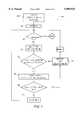
- FIG. 3is a flowchart depicting a method of aperiodically initiating self-testing of the defibrillator of FIG. 1.
- FIG. 4is a flowchart depicting a method of selecting time intervals in the method of FIG. 3.
- FIG. 5is a flowchart depicting a method of selecting test procedures to be initiated in the method of FIG. 3.
- defibrillator systemis described in U.S. Pat. No. 5,607,454, entitled “Electrotherapy Method and Apparatus,” the disclosure of which is incorporated herein by reference.
- Examples of defibrillators having automatic self-test featuresare described in U.S. Pat. No. 5,579,234, entitled “System for Automatically Testing an Electronic Device During Quiescent Periods,” and in U.S. Pat. No. 5,591,213, entitled “Defibrillator System Condition Indicator,” the disclosures of which are incorporated herein by reference.
- a defibrillatorwhich includes a testing circuit for automatically and aperiodically testing defibrillator functions. Test frequency and procedures may also be modified to account for conditions potentially affecting defibrillator reliability and performance.
- test frequency and proceduresmay also be modified to account for conditions potentially affecting defibrillator reliability and performance.
- FIG. 1is a functional block diagram depicting a defibrillator or AED 10 having a testing circuit or system monitor 12 in accordance with an embodiment of the present invention.
- the AED 10includes a power supply 13, which is powered by an energy source such as a removable battery 14.
- a controller or central processing unit (“CPU") 16controls the operation of the various components of the AED 10.
- a high voltage delivery circuit 18delivers a pulse of electrical energy to an electrode connector or interface 20, and then to a patient via electrodes 22.
- the high voltage delivery circuit 18typically includes a capacitor or a capacitor bank and appropriate switches (not shown), and delivery of the electrical pulse is controlled by the CPU 16.
- An ECG circuit 24acquires and processes the patient's ECG signals through the electrodes 22 and sends the signals to the CPU 16 via a system gate array 26.
- the system gate array 26is a custom application specific integrated circuit ("ASIC") integrating many of the defibrillator's functions, such as display control and many of the instrument control functions. Providing the separate system gate array 26 allows the CPU 16 to focus on other tasks. Alternatively, the functionality of the system gate array 26 could be included within the operations performed by the CPU 16, or could be replaced by discrete logic circuit components or a separately dedicated CPU.
- the AED 10also includes a memory device 30 (such as a removable personal computer memory card international association "PCMCIA”! card or a magnetic tape), a microphone 32, an audio speaker 34, a liquid crystal display (“LCD”) panel 36, and a set of push-button controls 38.
- PCMCIApersonal computer memory card international association
- LCDliquid crystal display
- the system monitor 12generates test signals at various times and in response to specified events, such as power-on events, to initiate testing of defibrillator functions.
- the system monitor 12can also operate a fail-safe defibrillator status indicator, which includes a visual test status indicator 40 (which may be integrated within the LCD display 36) and an audio test status indicator 42 (which may be integrated within the audio speaker 34).
- the system monitor 12applies test signals to the CPU 16 via a communication channel, and the CPU controls and gathers information from various tested defibrillator components via other communication channels, some of which pass through the system gate array 26.
- Each of the various tested defibrillator componentsmay itself contain circuitry (not shown) for testing and communicating component status to the CPU 16 and system monitor 12.
- the ECG circuit 24may include a signal generator for generating test ECG signals to test ECG amplifier and analog-to-digital converter functions, etc.
- the high voltage delivery circuit 18may include test load circuitry to which a high voltage pulse is delivered instead of to the electrode connector 20.
- the test load circuitrywould include relay circuitry to isolate the high voltage delivery circuit 18 from the electrode connector 20 and apply the high voltage pulse to a test load impedance.
- Other components of the AED 10may include similarly adapted circuitry for testing component function and communicating test results to the CPU 16 and the system monitor 12, as will be understood by those skilled in the art.
- the functionality of the system monitor 12could be included within the operations performed by the CPU 16. However, providing the separate system monitor 12 allows the CPU 16 to focus on other tasks.
- the testing circuitcan also be conveniently powered separately from other components of the AED 10, resulting in energy savings.
- the system monitor 12can then include its own separately dedicated power supply (not shown), which may be powered by the main battery 14 or by a separate dedicated battery (not shown).
- FIG. 2is a functional block diagram depicting certain details of the system monitor 12.
- a test controller 46executes primary functions of the system monitor 12.
- the test controller 46may itself be a CPU or a microcontroller operating under software control, or may be a gate array ASIC or other suitably adapted circuitry.
- the test controller 46controls operation of the visual and audible status indicators 40 and 42, and responds to power-on events, as depicted by the coupling with an on-button control 48.
- An ambient condition sensor 44is coupled with the test controller to provide signals corresponding to measured conditions such as temperature and humidity.
- a clock and timer circuit 50is coupled with the test controller 46 to provide clock signal functionality to the test controller and to provide signals associated with the timing of certain events.
- a memory 54is coupled with the test controller 46 to store data and instructions used by the test controller to execute test functions.
- a random number generator 52is shown coupled with the test controller 46 to provide signals corresponding to random numbers, which may be used for loading random time values in the clock and timer circuit 50. Alternatively, time values may be stored or otherwise determined from data stored in the memory 54.
- the clock and timer circuit 50Upon expiration of a given time interval, the clock and timer circuit 50 applies a control signal to the test controller 46 to initiate the various defibrillator self-test functions mediated by the test controller.
- the system monitor 12automatically tests defibrillator functions at random or otherwise aperiodic time intervals.
- the time intervalsmay be determined by the random number generator 52 providing signals for loading the timer circuit 50.
- the time intervalsmay be selected from a plurality of preprogrammed time values stored in the memory 54, with the selection of these values being random, sequential, etc.
- the time intervalscould be calculated or otherwise determined in accordance with any of a wide variety of non-periodic functions. Indeed, those skilled in the art will appreciate that any of numerous methods and suitably adapted circuitry may be employed for initiating defibrillator self-test functions at other than regular, periodic time intervals.
- aperiodic testingallows more accurate reliability testing than conventional periodic testing, which can inadvertently be synchronized with environmental conditions.
- Such aperiodic testingcan also be advantageously tailored to change the type and frequency of the self-test performed. For example, high energy tests (such as a full energy defibrillator discharge test) need not be performed as frequently as low energy tests. Also, the mean frequency of the aperiodic testing can be modified depending on ambient or other conditions encountered upon "wake-up" of the AED 10 for testing.
- an electronic devicesuch as the AED 10
- the AED 10is likely to fail or perform poorly when something unusual happens to it.
- its useis something unusual-such devices being designed to spend most of their service lives not being used.
- the AED 10may be dropped or exposed to wet conditions, and the battery 14 (see FIG. 1) suffers some depletion.
- near-term effectssuch as mechanical fatigue of circuit connections or corrosion may adversely impact defibrillator performance and reliability.
- the battery 14may be substantially depleted, although not quite reaching a low battery condition status. Consequently, the AED 10 is more likely to fail when being used, or soon thereafter, than when remaining in a standby condition for an extended period of time.
- the system monitor 12adjusts the mean frequency of the aperiodic testing to provide more frequent testing following the use of the AED 10. Such testing more effectively identifies failures precipitated by conditions during the use of the AED 10.
- the time intervals separating defibrillator self-test operationsare made gradually larger as increasing numbers of tests are passed successfully, since a determination of consistently stable defibrillator functions justifies increasing the time intervals between successive tests of those functions.
- the time interval spacingmay, for example, follow a logarithmic progression until normal standby test intervals are warranted.
- the repair of the AED 10might also warrant more frequent initial testing. Similarly, more frequent testing can be performed soon after manufacture of the AED 10, to more rapidly identify any "infant mortality" effects. Later in the life of the AED 10 (as a function of time from manufacture, number of shocks delivered, use history, repair history, etc.), the frequency of testing can gradually increase to identify wear-out failures more quickly.
- test proceduresmay be performed more frequently than others. For example, cold temperatures adversely affect battery performance, but do not otherwise normally affect many of the other defibrillator components. If the temperature tends to be cold upon wake-ups, the mean interval of high energy testing can be extended in order to minimize battery drain. If, however, high humidity is detected, high energy testing can be performed more frequently to determine if the humidity is adversely affecting high voltage performance.
- the frequency of battery testingmay be adjusted as a function of the battery's age and/or history of use of the battery in AED 10. In later battery life, increasingly frequent testing will tend to decrease the exposure to any marginal battery conditions while the AED 10 is in standby mode. As the battery begins to reach a depletion stage, increasingly frequent testing will itself accelerate the depletion of the battery, thereby accelerating the needed replacement of the battery.
- Such aperiodic testingachieves a number of important advantages. Failures precipitated by use of the AED 10 are detected sooner. The mean energy required for testing can, in the long run, be less than that required for traditional periodic testing methods, resulting in improved battery life. It is also possible that a data trend analysis of variables measured during post-use testing can be predictive of failure, thereby allowing the AED 10 to be repaired prior to an actual failure. Those skilled in the art will also appreciate further advantages achievable by the above-described aperiodic testing.
- FIG. 3is a flow chart depicting a method 60 of aperiodically initiating selftesting of the AED 10.
- one or more condition parametersare determined.
- Example condition parametersinclude ambient conditions such as temperature and humidity, the number of uses of the AED 10 and/or the time since the last such use, the age of the AED 10 or the battery's state of change (as a function of time from manufacture, number of shocks delivered, use history, etc.), parameters relating to the repair and/or component replacement, etc.
- step 64a time interval corresponding to the determined condition parameter(s) is selected. Following elapse of the time interval (depicted as a wait state 66), defibrillator self-test operations are initiated in step 68.
- condition parameterscan be accomplished in any number of ways. Of course, determining ambient conditions, such as temperature and humidity, is most conveniently done by measuring such conditions with the sensor 44 (see FIG. 2).
- the time elapsed since a most recent use of the AED 10may be provided by the clock and timer circuit 50, or may be determined from data stored in the memory 54.
- Parameters associated with the repair history, use history, and age of the AED 10can also be determined from data stored in the memory 54 data which is updated according to the occurrence of events pertinent to such condition parameters, as will be clear to those skilled in the art.
- the battery's state of changecan be determined by measuring the battery's terminal voltage and the battery's response under load.
- the time interval corresponding to the determined condition parameter(s)can be selected or otherwise determined according to any of a wide variety of methods consistent with the above description of varying the frequency of defibrillator testing.
- FIG. 4is a flow chart depicting one such method 64.
- a test interval or range of valuesis selected in correspondence with the determined condition parameter(s).
- This test intervalmay represent a range of values corresponding to an acceptable range of time intervals between successive testing of defibrillator functions, given the determined condition parameter(s), as will be understood by those skilled in the art. Following a use of the AED 10, for example, successive test interval means may follow a roughly logarithmic progression until normal standby testing is again warranted.
- a random numberis then generated in step 72, and a conditional branch step 74 is performed, in which the generated random number is compared to the test interval. If the random number is not an element of the test interval, the method returns to step 72, in which another random number is generated. If, instead, the random number is an element of the test interval, a time interval is selected corresponding to that random number in step 76. The time interval may simply be equal to the random number, or may be correspondingly calculated, selected graphically or from a look-up table, etc.
- FIGS. 3 and 4are just one of many methods of initiating defibrillator self-test operations at aperiodic time intervals.
- the selection and order of certain stepscan be readily modified, with some steps omitted and others added. Any of a number of suitable methods may be employed to select a random time interval, whether selected in correspondence with particular condition parameters or not. Also, selecting a random time interval is just one example of, more generally, selecting or otherwise determining a time interval that is not regular or periodic.
- FIGS. 3 and 4combines self-testing of defibrillator functions at random time intervals with self-testing at frequencies dictated by the determined condition parameter(s).
- the scope of the present inventionalso includes solely testing at random or otherwise aperiodic time intervals, as well as solely testing at frequencies adjusted in accordance with determined condition parameters.
- the step 68 depicted in FIG. 3can include the determination of which test procedure should be performed. Any of a number of acceptable methods can be employed for such a determination.
- One such method 68is shown in FIG. 5.
- a test time valueis selected or otherwise determined corresponding to the condition parameter(s) determined in step 62 of FIG. 3.
- the test time valuemay represent a minimum acceptable time interval between successive performance of a particular category of test procedures, given the determined condition parameter(s), as will be understood by those skilled in the art.
- An integral value Nis set to zero in step 86 and compared to a maximum value N MAX in a conditional branch step 88.
- the value N MAXreflects the number of distinct test procedures that can be performed during defibrillator self-test operations. If the value N exceeds N MAX , then defibrillator self-testing operations are concluded. Otherwise, a test procedure corresponding to the value N is selected in step 90.
- a conditional branch step 92determines whether the selected test procedure is an element of a selected category of test procedures, such as high energy tests. If not, the test procedure is performed in step 94. If, however, the selected test procedure is of the selected category, a determination of a last-tested time interval (the time elapsed since a most recent performance of the test procedure) is determined in step 96. A conditional branch step 98 is then performed in which the last-tested time interval is compared to the previously selected test time value. If the last-tested time interval exceeds the test time value, performance of the selected test procedure is initiated in step 94. If, however, the last-tested time value does not exceed the selected test time, the value N is incremented by 1 in step 99, and the sequence of operations branches back to conditional branch step 88, in which the value N is compared to the maximum value N MAX .
- FIG. 5is just one of many methods of adjusting the frequency of defibrillator self-test operations for certain selected test procedures.
- the selection and order of certain stepscan be readily modified, with some steps omitted and others added. Any of a number of suitable methods may be employed to appropriately adjust the frequency of selected test procedures, whether adjusted in correspondence with particular condition parameters or not.
- the method depicted in FIG. 5selectively initiates test procedures depending on whether or not they belong to a single selected category. However, those skilled in the art will appreciate that this method can be readily adapted to identify and initiate test 10 procedures according to multiple categories.
- each of the circuits whose function and interconnection is described in connection with FIGS. 1 and 2is of a type known in the art, and one skilled in the art would be able to use such circuits in the described combination to practice the present invention.
- the internal details of these particular circuitsare not part of, nor critical to, the invention. Therefore, a detailed description of the internal circuit operation is not required.
- each of the steps depicted in FIGS. 3-5is of a type well known in the art and may itself include a sequence of operations which need not be described herein.
Landscapes
- Health & Medical Sciences (AREA)
- Cardiology (AREA)
- Heart & Thoracic Surgery (AREA)
- Engineering & Computer Science (AREA)
- Biomedical Technology (AREA)
- Nuclear Medicine, Radiotherapy & Molecular Imaging (AREA)
- Radiology & Medical Imaging (AREA)
- Life Sciences & Earth Sciences (AREA)
- Animal Behavior & Ethology (AREA)
- General Health & Medical Sciences (AREA)
- Public Health (AREA)
- Veterinary Medicine (AREA)
- Electrotherapy Devices (AREA)
Abstract
Description
Claims (74)
Priority Applications (1)
| Application Number | Priority Date | Filing Date | Title |
|---|---|---|---|
| US08/910,970US5899925A (en) | 1997-08-07 | 1997-08-07 | Method and apparatus for aperiodic self-testing of a defibrillator |
Applications Claiming Priority (1)
| Application Number | Priority Date | Filing Date | Title |
|---|---|---|---|
| US08/910,970US5899925A (en) | 1997-08-07 | 1997-08-07 | Method and apparatus for aperiodic self-testing of a defibrillator |
Publications (1)
| Publication Number | Publication Date |
|---|---|
| US5899925Atrue US5899925A (en) | 1999-05-04 |
Family
ID=25429586
Family Applications (1)
| Application Number | Title | Priority Date | Filing Date |
|---|---|---|---|
| US08/910,970Expired - LifetimeUS5899925A (en) | 1997-08-07 | 1997-08-07 | Method and apparatus for aperiodic self-testing of a defibrillator |
Country Status (1)
| Country | Link |
|---|---|
| US (1) | US5899925A (en) |
Cited By (24)
| Publication number | Priority date | Publication date | Assignee | Title |
|---|---|---|---|---|
| US6317633B1 (en) | 1999-01-19 | 2001-11-13 | Medtronic, Inc. | Implantable lead functional status monitor and method |
| US6329822B1 (en) | 2000-02-11 | 2001-12-11 | Daniel J. Powers | Periodic automatic self-test system and methodology |
| US20030055681A1 (en)* | 2001-08-27 | 2003-03-20 | Klaus Abraham-Fuchs | Quality control in disease management services |
| US6586850B1 (en) | 2000-07-05 | 2003-07-01 | Koninklijke Philips Electronics N.V. | Device with multiple, concurrently-installed power molecules and method for controlling same |
| EP1382369A1 (en) | 2002-07-20 | 2004-01-21 | Schiller AG | Device for electrotherapy and method of testing and operating the same |
| GB2402747A (en)* | 2003-06-14 | 2004-12-15 | Desmond Bryan Mills | Self-test system for a medical device |
| US20050277991A1 (en)* | 2004-06-10 | 2005-12-15 | Covey Kevin K | Assessing medical electrode condition |
| US20060136000A1 (en)* | 2004-11-18 | 2006-06-22 | Bowers Kyle R | System and method for performing self-test in an automatic external defibrillator (AED) |
| US20070032830A1 (en)* | 2005-08-04 | 2007-02-08 | Bowers Kyle R | Automatic external defibrillator (AED) with wireless communications |
| EP1795984A1 (en)* | 2005-11-18 | 2007-06-13 | General Electric Company | Functionality test method |
| US20080147136A1 (en)* | 2006-12-18 | 2008-06-19 | Shenzhen Mindray Bio-Medical Electronics Co., Ltd | Method and apparatus for automatic self-test of medical device |
| US20090248100A1 (en)* | 2008-03-28 | 2009-10-01 | Defibtech, Llc | System and Method for Conditioning a Lithium Battery in an Automatic External Defibrillator |
| EP1289603B1 (en)* | 2000-06-12 | 2009-10-07 | Cardiac Science, Inc. | A public access defibrillator |
| JP2015526228A (en)* | 2012-08-29 | 2015-09-10 | コーニンクレッカ フィリップス エヌ ヴェ | Environmental and usage monitoring system for advanced life support devices |
| JP2016500286A (en)* | 2012-12-17 | 2016-01-12 | コーニンクレッカ フィリップス エヌ ヴェKoninklijke Philips N.V. | Adaptive self-test and stress analysis of medical devices |
| US20180001097A1 (en)* | 2014-12-30 | 2018-01-04 | Koninklijke Philips N.V. | Advanced warning indicator for emergency medical devices |
| US10155118B2 (en) | 2013-08-01 | 2018-12-18 | Zoll Medical Corporation | Systems and methods for utilizing identification devices in a wearable medical therapy device |
| US10272010B2 (en) | 2015-03-20 | 2019-04-30 | Zoll Medical Corporation | Systems and methods for testing a medical device |
| US10426342B2 (en) | 2016-03-31 | 2019-10-01 | Zoll Medical Corporation | Remote access for ambulatory medical device |
| US10561852B2 (en) | 2016-02-26 | 2020-02-18 | Zoll Medical Corporation | Systems and methods for providing rapid medical care |
| CN114009066A (en)* | 2019-07-03 | 2022-02-01 | 深圳迈瑞生物医疗电子股份有限公司 | Defibrillator and Management Server |
| US11549684B2 (en)* | 2018-08-27 | 2023-01-10 | Honeywell International Inc. | Burner system control |
| US11709747B2 (en) | 2016-01-08 | 2023-07-25 | Zoll Medical Corporation | Patient assurance system and method |
| WO2025066069A1 (en)* | 2023-09-27 | 2025-04-03 | 普美康(江苏)医疗科技有限公司 | Defibrillation electrode pad assembly, device, defibrillation electrode pad loss estimation method, and medium |
Citations (59)
| Publication number | Priority date | Publication date | Assignee | Title |
|---|---|---|---|---|
| US3747605A (en)* | 1971-10-20 | 1973-07-24 | Beaumont Hospital William | Defibillator and method and apparatus for calibrating, testing, monitoring and/or controlling a defibrillator or the like |
| FR2172681A5 (en)* | 1972-02-16 | 1973-09-28 | Siemens Ag | |
| US3983476A (en)* | 1974-06-28 | 1976-09-28 | Francis Konopasek | Defibrillator testing device |
| DE2712352A1 (en)* | 1977-03-21 | 1978-09-28 | Mela Gmbh Elektromedizin | Defibrillator electrode testing circuit - has load resistance followed by rectifier bridge and measuring instrument with quenching switch |
| US4164946A (en)* | 1977-05-27 | 1979-08-21 | Mieczyslaw Mirowski | Fault detection circuit for permanently implanted cardioverter |
| US4295474A (en)* | 1979-10-02 | 1981-10-20 | The Johns Hopkins University | Recorder with patient alarm and service request systems suitable for use with automatic implantable defibrillator |
| US4300567A (en)* | 1980-02-11 | 1981-11-17 | Mieczyslaw Mirowski | Method and apparatus for effecting automatic ventricular defibrillation and/or demand cardioversion through the means of an implanted automatic defibrillator |
| US4353372A (en)* | 1980-02-11 | 1982-10-12 | Bunker Ramo Corporation | Medical cable set and electrode therefor |
| US4404972A (en)* | 1981-05-18 | 1983-09-20 | Intermedics, Inc. | Implantable device with microprocessor control |
| US4407288A (en)* | 1981-02-18 | 1983-10-04 | Mieczyslaw Mirowski | Implantable heart stimulator and stimulation method |
| US4442315A (en)* | 1980-11-17 | 1984-04-10 | Fukuda Denshi Kabushiki Kaisha | X-Ray transmissive electrode-shielded wire assembly and manufacture thereof |
| US4488555A (en)* | 1982-12-13 | 1984-12-18 | Mieczyslaw Mirowski | Battery condition warning system for medical implant |
| US4494552A (en)* | 1980-08-08 | 1985-01-22 | R2 Corporation | Physiological monitoring electrode system |
| US4504773A (en)* | 1981-09-10 | 1985-03-12 | Kureha Kagaku Kogyo Kabushiki Kaisha | Capacitor discharge circuit |
| US4523595A (en)* | 1981-11-25 | 1985-06-18 | Zibell J Scott | Method and apparatus for automatic detection and treatment of ventricular fibrillation |
| US4543958A (en)* | 1979-04-30 | 1985-10-01 | Ndm Corporation | Medical electrode assembly |
| US4574810A (en)* | 1984-10-05 | 1986-03-11 | Lerman Bruce B | Automatic threshold defibrillator |
| US4583549A (en)* | 1984-05-30 | 1986-04-22 | Samir Manoli | ECG electrode pad |
| US4595009A (en)* | 1984-02-06 | 1986-06-17 | Medtronic, Inc. | Protection circuit for implantable cardioverter |
| US4610254A (en)* | 1984-03-08 | 1986-09-09 | Physio-Control Corporation | Interactive portable defibrillator |
| US4625730A (en)* | 1985-04-09 | 1986-12-02 | The Johns Hopkins University | Patient ECG recording control for an automatic implantable defibrillator |
| US4628935A (en)* | 1985-01-08 | 1986-12-16 | Physio-Control Corporation | Defibrillator adapted for use with accessory cassettes |
| US4733670A (en)* | 1985-10-11 | 1988-03-29 | The Kendall Company | Device for cardiac output monitoring |
| US4745923A (en)* | 1985-11-20 | 1988-05-24 | Intermedics, Inc. | Protection apparatus for patient-implantable device |
| US4771781A (en)* | 1986-10-03 | 1988-09-20 | Lerman Bruce B | Current-based defibrillating method |
| US4785812A (en)* | 1986-11-26 | 1988-11-22 | First Medical Devices Corporation | Protection system for preventing defibrillation with incorrect or improperly connected electrodes |
| US4852572A (en)* | 1987-03-30 | 1989-08-01 | Fukuda Denshi Co., Ltd. | Multi-electrode type electrocardiographic electrode structure |
| EP0327304A1 (en)* | 1988-02-01 | 1989-08-09 | Physio-Control Corporation | Disposable stimulation electrode with long shelf life and improved current density profile |
| US4895169A (en)* | 1980-08-08 | 1990-01-23 | Darox Corporation | Disposable non-invasive stimulating electrode set |
| US4957109A (en)* | 1988-08-22 | 1990-09-18 | Cardiac Spectrum Technologies, Inc. | Electrocardiograph system |
| US5078134A (en)* | 1988-04-25 | 1992-01-07 | Lifecor, Inc. | Portable device for sensing cardiac function and automatically delivering electrical therapy |
| US5080099A (en)* | 1988-08-26 | 1992-01-14 | Cardiotronics, Inc. | Multi-pad, multi-function electrode |
| EP0472411A1 (en)* | 1990-08-21 | 1992-02-26 | Telectronics N.V. | Implantable ambulatory electrocardiogram monitor |
| US5097830A (en)* | 1990-03-30 | 1992-03-24 | Laerdal Manufacturing Corporation | Defibrillator with reliability verification |
| US5099844A (en)* | 1988-12-22 | 1992-03-31 | Biofield Corp. | Discriminant function analysis method and apparatus for disease diagnosis and screening |
| US5168875A (en)* | 1991-04-11 | 1992-12-08 | Staodyn, Inc. | Elongated strip electrode arrangement and method |
| US5184620A (en)* | 1991-12-26 | 1993-02-09 | Marquette Electronics, Inc. | Method of using a multiple electrode pad assembly |
| US5191886A (en)* | 1991-04-18 | 1993-03-09 | Physio-Control Corporation | Multiple electrode strip |
| US5201865A (en)* | 1991-10-28 | 1993-04-13 | Medtronic, Inc. | Medical lead impedance measurement system |
| US5222830A (en)* | 1992-01-15 | 1993-06-29 | Combo Manufacturing, Inc. | Combined dock and boat lift |
| US5224870A (en)* | 1991-01-11 | 1993-07-06 | Physio-Control Corporation | Battery pack |
| EP0551746A2 (en)* | 1992-01-10 | 1993-07-21 | Physio-Control Corporation | Detection of electrode/patient motion and fast restore limits |
| US5231987A (en)* | 1992-04-10 | 1993-08-03 | Random Technologies, Inc. | Time domain reflectometer-integrity testing system and method for implantable electrode |
| US5237991A (en)* | 1991-11-19 | 1993-08-24 | Cyberonics, Inc. | Implantable medical device with dummy load for pre-implant testing in sterile package and facilitating electrical lead connection |
| WO1993016759A1 (en)* | 1992-02-21 | 1993-09-02 | Zmd Corporation | Defibrillation discharge circuit test |
| GB2272376A (en)* | 1992-11-13 | 1994-05-18 | Eric Thomas Mcadams | Multi-function multi-electrode device for medical use |
| US5327888A (en)* | 1992-06-05 | 1994-07-12 | Physiometrix, Inc. | Precordial electrode strip and apparatus and method using the same |
| US5330526A (en)* | 1992-05-01 | 1994-07-19 | Zmd Corporation | Combined defibrillation and pacing electrode |
| US5342403A (en)* | 1993-04-09 | 1994-08-30 | Hewlett-Packard Corporation | Integrated defibrillator/monitor architecture with defibrillator-only fail-safe mode of operation |
| WO1994027674A1 (en)* | 1993-05-18 | 1994-12-08 | Heartstream, Inc. | Defibrillator with self-test features |
| US5400782A (en)* | 1992-10-07 | 1995-03-28 | Graphic Controls Corporation | Integral medical electrode including a fusible conductive substrate |
| US5402884A (en)* | 1992-09-24 | 1995-04-04 | Surviva Link Corporation | Medical electrode packaging technology |
| EP0671687A2 (en)* | 1994-03-11 | 1995-09-13 | SpaceLabs Medical, Inc. | System for automatically testing an electronic device during quiescent periods |
| US5462157A (en)* | 1993-10-28 | 1995-10-31 | Zmd Corporation | Electrode package |
| US5467768A (en)* | 1993-03-17 | 1995-11-21 | Nihon Koden Corporation | Multi-purpose sensor |
| US5549646A (en)* | 1994-12-06 | 1996-08-27 | Pacesetter, Inc. | Periodic electrical lead intergrity testing system and method for implantable cardiac stimulating devices |
| US5591213A (en)* | 1993-05-18 | 1997-01-07 | Heartstream, Inc. | Defibrillator system condition indictator |
| US5607454A (en)* | 1993-08-06 | 1997-03-04 | Heartstream, Inc. | Electrotherapy method and apparatus |
| US5645571A (en)* | 1995-08-01 | 1997-07-08 | Survivalink Corporation | Automated external defibrillator with lid activated self-test system |
- 1997
- 1997-08-07USUS08/910,970patent/US5899925A/ennot_activeExpired - Lifetime
Patent Citations (66)
| Publication number | Priority date | Publication date | Assignee | Title |
|---|---|---|---|---|
| US3747605A (en)* | 1971-10-20 | 1973-07-24 | Beaumont Hospital William | Defibillator and method and apparatus for calibrating, testing, monitoring and/or controlling a defibrillator or the like |
| FR2172681A5 (en)* | 1972-02-16 | 1973-09-28 | Siemens Ag | |
| US3983476A (en)* | 1974-06-28 | 1976-09-28 | Francis Konopasek | Defibrillator testing device |
| DE2712352A1 (en)* | 1977-03-21 | 1978-09-28 | Mela Gmbh Elektromedizin | Defibrillator electrode testing circuit - has load resistance followed by rectifier bridge and measuring instrument with quenching switch |
| US4164946A (en)* | 1977-05-27 | 1979-08-21 | Mieczyslaw Mirowski | Fault detection circuit for permanently implanted cardioverter |
| US4543958A (en)* | 1979-04-30 | 1985-10-01 | Ndm Corporation | Medical electrode assembly |
| US4295474A (en)* | 1979-10-02 | 1981-10-20 | The Johns Hopkins University | Recorder with patient alarm and service request systems suitable for use with automatic implantable defibrillator |
| US4300567A (en)* | 1980-02-11 | 1981-11-17 | Mieczyslaw Mirowski | Method and apparatus for effecting automatic ventricular defibrillation and/or demand cardioversion through the means of an implanted automatic defibrillator |
| US4353372A (en)* | 1980-02-11 | 1982-10-12 | Bunker Ramo Corporation | Medical cable set and electrode therefor |
| US4494552A (en)* | 1980-08-08 | 1985-01-22 | R2 Corporation | Physiological monitoring electrode system |
| US4895169A (en)* | 1980-08-08 | 1990-01-23 | Darox Corporation | Disposable non-invasive stimulating electrode set |
| US4442315A (en)* | 1980-11-17 | 1984-04-10 | Fukuda Denshi Kabushiki Kaisha | X-Ray transmissive electrode-shielded wire assembly and manufacture thereof |
| US4539995A (en)* | 1980-11-17 | 1985-09-10 | Fukuda Denshi Kabushiki Kaisha | X-Ray transmissive electrode-shielded wire assembly |
| US4407288B1 (en)* | 1981-02-18 | 2000-09-19 | Mieczyslaw Mirowski | Implantable heart stimulator and stimulation method |
| US4407288A (en)* | 1981-02-18 | 1983-10-04 | Mieczyslaw Mirowski | Implantable heart stimulator and stimulation method |
| US4404972A (en)* | 1981-05-18 | 1983-09-20 | Intermedics, Inc. | Implantable device with microprocessor control |
| US4404972B1 (en)* | 1981-05-18 | 2000-07-11 | Intermedics Inc | Implantable device with microprocessor control |
| US4504773A (en)* | 1981-09-10 | 1985-03-12 | Kureha Kagaku Kogyo Kabushiki Kaisha | Capacitor discharge circuit |
| US4523595A (en)* | 1981-11-25 | 1985-06-18 | Zibell J Scott | Method and apparatus for automatic detection and treatment of ventricular fibrillation |
| US4488555A (en)* | 1982-12-13 | 1984-12-18 | Mieczyslaw Mirowski | Battery condition warning system for medical implant |
| US4595009A (en)* | 1984-02-06 | 1986-06-17 | Medtronic, Inc. | Protection circuit for implantable cardioverter |
| US4610254A (en)* | 1984-03-08 | 1986-09-09 | Physio-Control Corporation | Interactive portable defibrillator |
| US4583549A (en)* | 1984-05-30 | 1986-04-22 | Samir Manoli | ECG electrode pad |
| US4574810A (en)* | 1984-10-05 | 1986-03-11 | Lerman Bruce B | Automatic threshold defibrillator |
| US4628935A (en)* | 1985-01-08 | 1986-12-16 | Physio-Control Corporation | Defibrillator adapted for use with accessory cassettes |
| US4625730A (en)* | 1985-04-09 | 1986-12-02 | The Johns Hopkins University | Patient ECG recording control for an automatic implantable defibrillator |
| US4733670A (en)* | 1985-10-11 | 1988-03-29 | The Kendall Company | Device for cardiac output monitoring |
| US4745923A (en)* | 1985-11-20 | 1988-05-24 | Intermedics, Inc. | Protection apparatus for patient-implantable device |
| US4771781A (en)* | 1986-10-03 | 1988-09-20 | Lerman Bruce B | Current-based defibrillating method |
| US4785812A (en)* | 1986-11-26 | 1988-11-22 | First Medical Devices Corporation | Protection system for preventing defibrillation with incorrect or improperly connected electrodes |
| US4852572A (en)* | 1987-03-30 | 1989-08-01 | Fukuda Denshi Co., Ltd. | Multi-electrode type electrocardiographic electrode structure |
| EP0327304A1 (en)* | 1988-02-01 | 1989-08-09 | Physio-Control Corporation | Disposable stimulation electrode with long shelf life and improved current density profile |
| US5078134A (en)* | 1988-04-25 | 1992-01-07 | Lifecor, Inc. | Portable device for sensing cardiac function and automatically delivering electrical therapy |
| US4957109A (en)* | 1988-08-22 | 1990-09-18 | Cardiac Spectrum Technologies, Inc. | Electrocardiograph system |
| US5080099A (en)* | 1988-08-26 | 1992-01-14 | Cardiotronics, Inc. | Multi-pad, multi-function electrode |
| US5099844A (en)* | 1988-12-22 | 1992-03-31 | Biofield Corp. | Discriminant function analysis method and apparatus for disease diagnosis and screening |
| US5097830A (en)* | 1990-03-30 | 1992-03-24 | Laerdal Manufacturing Corporation | Defibrillator with reliability verification |
| EP0472411A1 (en)* | 1990-08-21 | 1992-02-26 | Telectronics N.V. | Implantable ambulatory electrocardiogram monitor |
| US5224870A (en)* | 1991-01-11 | 1993-07-06 | Physio-Control Corporation | Battery pack |
| US5168875A (en)* | 1991-04-11 | 1992-12-08 | Staodyn, Inc. | Elongated strip electrode arrangement and method |
| US5191886A (en)* | 1991-04-18 | 1993-03-09 | Physio-Control Corporation | Multiple electrode strip |
| US5201865A (en)* | 1991-10-28 | 1993-04-13 | Medtronic, Inc. | Medical lead impedance measurement system |
| US5237991A (en)* | 1991-11-19 | 1993-08-24 | Cyberonics, Inc. | Implantable medical device with dummy load for pre-implant testing in sterile package and facilitating electrical lead connection |
| US5184620A (en)* | 1991-12-26 | 1993-02-09 | Marquette Electronics, Inc. | Method of using a multiple electrode pad assembly |
| EP0551746A2 (en)* | 1992-01-10 | 1993-07-21 | Physio-Control Corporation | Detection of electrode/patient motion and fast restore limits |
| US5222830A (en)* | 1992-01-15 | 1993-06-29 | Combo Manufacturing, Inc. | Combined dock and boat lift |
| WO1993016759A1 (en)* | 1992-02-21 | 1993-09-02 | Zmd Corporation | Defibrillation discharge circuit test |
| US5249573A (en)* | 1992-02-21 | 1993-10-05 | Zmd Corporation | Defibrillation discharge circuit test |
| US5231987A (en)* | 1992-04-10 | 1993-08-03 | Random Technologies, Inc. | Time domain reflectometer-integrity testing system and method for implantable electrode |
| US5330526A (en)* | 1992-05-01 | 1994-07-19 | Zmd Corporation | Combined defibrillation and pacing electrode |
| US5327888A (en)* | 1992-06-05 | 1994-07-12 | Physiometrix, Inc. | Precordial electrode strip and apparatus and method using the same |
| US5402884A (en)* | 1992-09-24 | 1995-04-04 | Surviva Link Corporation | Medical electrode packaging technology |
| US5400782A (en)* | 1992-10-07 | 1995-03-28 | Graphic Controls Corporation | Integral medical electrode including a fusible conductive substrate |
| US5466256A (en)* | 1992-11-13 | 1995-11-14 | Mcadams; Eric T. | Multi-function multi-electrode device |
| GB2272376A (en)* | 1992-11-13 | 1994-05-18 | Eric Thomas Mcadams | Multi-function multi-electrode device for medical use |
| US5467768A (en)* | 1993-03-17 | 1995-11-21 | Nihon Koden Corporation | Multi-purpose sensor |
| US5342403A (en)* | 1993-04-09 | 1994-08-30 | Hewlett-Packard Corporation | Integrated defibrillator/monitor architecture with defibrillator-only fail-safe mode of operation |
| WO1994027674A1 (en)* | 1993-05-18 | 1994-12-08 | Heartstream, Inc. | Defibrillator with self-test features |
| US5591213A (en)* | 1993-05-18 | 1997-01-07 | Heartstream, Inc. | Defibrillator system condition indictator |
| US5607454A (en)* | 1993-08-06 | 1997-03-04 | Heartstream, Inc. | Electrotherapy method and apparatus |
| US5462157A (en)* | 1993-10-28 | 1995-10-31 | Zmd Corporation | Electrode package |
| EP0671687A2 (en)* | 1994-03-11 | 1995-09-13 | SpaceLabs Medical, Inc. | System for automatically testing an electronic device during quiescent periods |
| US5579234A (en)* | 1994-03-11 | 1996-11-26 | Physio-Control Corporation | System for automatically testing an electronic device during quiescent periods |
| US5549646A (en)* | 1994-12-06 | 1996-08-27 | Pacesetter, Inc. | Periodic electrical lead intergrity testing system and method for implantable cardiac stimulating devices |
| US5645571B1 (en)* | 1995-08-01 | 1999-08-24 | Surviva Link Corp | Automated external defibrillator with lid activated self-test system |
| US5645571A (en)* | 1995-08-01 | 1997-07-08 | Survivalink Corporation | Automated external defibrillator with lid activated self-test system |
Non-Patent Citations (1)
| Title |
|---|
| Product Brochure from Vivalink AED Automatic External Defibrillator System by Survivalink Corporation.* |
Cited By (51)
| Publication number | Priority date | Publication date | Assignee | Title |
|---|---|---|---|---|
| US6317633B1 (en) | 1999-01-19 | 2001-11-13 | Medtronic, Inc. | Implantable lead functional status monitor and method |
| US6329822B1 (en) | 2000-02-11 | 2001-12-11 | Daniel J. Powers | Periodic automatic self-test system and methodology |
| EP1289603B1 (en)* | 2000-06-12 | 2009-10-07 | Cardiac Science, Inc. | A public access defibrillator |
| EP2116276A3 (en)* | 2000-06-12 | 2010-12-01 | Cardiac Science Corporation | A public access defibrillator |
| US6586850B1 (en) | 2000-07-05 | 2003-07-01 | Koninklijke Philips Electronics N.V. | Device with multiple, concurrently-installed power molecules and method for controlling same |
| US6784568B2 (en) | 2000-07-05 | 2004-08-31 | Koninklijke Philips Electronics N.V. | Device with multiple, concurrently-installed power modules and method for controlling same |
| US20030055681A1 (en)* | 2001-08-27 | 2003-03-20 | Klaus Abraham-Fuchs | Quality control in disease management services |
| US7200535B2 (en)* | 2001-08-27 | 2007-04-03 | Siemens Aktiengesellschaft | Quality control in disease management services |
| EP1382369A1 (en) | 2002-07-20 | 2004-01-21 | Schiller AG | Device for electrotherapy and method of testing and operating the same |
| US20040030355A1 (en)* | 2002-07-20 | 2004-02-12 | Schiller Ag | Apparatus for electrotherapy and method for testing and operating same |
| EP1633435A1 (en)* | 2003-06-14 | 2006-03-15 | Mills, Desmond Bryan | A self test system for a medical device |
| US20060217775A1 (en)* | 2003-06-14 | 2006-09-28 | Ika Medical Products Llp | Self test system for a medical device |
| WO2004112900A1 (en) | 2003-06-14 | 2004-12-29 | Brown, Stephen, Colin | A selt test system for a medical device |
| GB2402747B (en)* | 2003-06-14 | 2007-05-09 | Desmond Bryan Mills | A medical device including a self test system |
| GB2402747A (en)* | 2003-06-14 | 2004-12-15 | Desmond Bryan Mills | Self-test system for a medical device |
| US20050277991A1 (en)* | 2004-06-10 | 2005-12-15 | Covey Kevin K | Assessing medical electrode condition |
| US8116864B2 (en) | 2004-06-10 | 2012-02-14 | Physio-Control, Inc. | Assessing medical electrode condition |
| US8005552B2 (en) | 2004-06-10 | 2011-08-23 | Physio-Control, Inc. | Assessing medical electrode condition |
| US20090048636A1 (en)* | 2004-06-10 | 2009-02-19 | Medtronic Emergency Response Systems, Inc. | Assessing medical electrode condition |
| US20090088810A1 (en)* | 2004-06-10 | 2009-04-02 | Medtronic Emergency | Assessing medical electrode condition |
| US7526345B2 (en)* | 2004-06-10 | 2009-04-28 | Medtronic Emergency Response Systems, Inc. | Assessing medical electrode condition |
| US20060136000A1 (en)* | 2004-11-18 | 2006-06-22 | Bowers Kyle R | System and method for performing self-test in an automatic external defibrillator (AED) |
| US20070032830A1 (en)* | 2005-08-04 | 2007-02-08 | Bowers Kyle R | Automatic external defibrillator (AED) with wireless communications |
| CN101021428B (en)* | 2005-11-18 | 2010-10-27 | 通用电气公司 | Functionality test method |
| EP1795984A1 (en)* | 2005-11-18 | 2007-06-13 | General Electric Company | Functionality test method |
| US20080147136A1 (en)* | 2006-12-18 | 2008-06-19 | Shenzhen Mindray Bio-Medical Electronics Co., Ltd | Method and apparatus for automatic self-test of medical device |
| US8065004B2 (en)* | 2006-12-18 | 2011-11-22 | Shenzhen Mindray Bio-Medical Electronics Co., Ltd. | Method and apparatus for automatic self-test of medical device |
| US20120265264A1 (en)* | 2008-03-28 | 2012-10-18 | Defibtech, Llc | System and Method for Conditioning a Lithium Battery in an Automatic External Defibrillator |
| US20090248100A1 (en)* | 2008-03-28 | 2009-10-01 | Defibtech, Llc | System and Method for Conditioning a Lithium Battery in an Automatic External Defibrillator |
| JP2015526228A (en)* | 2012-08-29 | 2015-09-10 | コーニンクレッカ フィリップス エヌ ヴェ | Environmental and usage monitoring system for advanced life support devices |
| JP2016500286A (en)* | 2012-12-17 | 2016-01-12 | コーニンクレッカ フィリップス エヌ ヴェKoninklijke Philips N.V. | Adaptive self-test and stress analysis of medical devices |
| EP3222320A1 (en)* | 2012-12-17 | 2017-09-27 | Koninklijke Philips N.V. | Adaptive self-testing and stress analysis of medical devices |
| US11129997B2 (en) | 2012-12-17 | 2021-09-28 | Koninklijke Philips N.V. | Adaptive self-testing and stress analysis of medical devices |
| US10029108B2 (en) | 2012-12-17 | 2018-07-24 | Koninklijke Philips N.V. | Adaptive self-testing and stress analysis of medical devices |
| JP2018134447A (en)* | 2012-12-17 | 2018-08-30 | コーニンクレッカ フィリップス エヌ ヴェKoninklijke Philips N.V. | Adaptive self-testing and stress analysis of medical devices |
| US10155118B2 (en) | 2013-08-01 | 2018-12-18 | Zoll Medical Corporation | Systems and methods for utilizing identification devices in a wearable medical therapy device |
| US10201714B2 (en)* | 2014-12-30 | 2019-02-12 | Koninklijke Philips N.V. | Advanced warning indicator for emergency medical devices |
| US20180001097A1 (en)* | 2014-12-30 | 2018-01-04 | Koninklijke Philips N.V. | Advanced warning indicator for emergency medical devices |
| US11213211B2 (en) | 2015-03-20 | 2022-01-04 | Zoll Medical Corporation | Systems and methods for testing a medical device |
| US10744057B2 (en) | 2015-03-20 | 2020-08-18 | Zoll Medical Corporation | Systems and methods for testing a medical device |
| US10272010B2 (en) | 2015-03-20 | 2019-04-30 | Zoll Medical Corporation | Systems and methods for testing a medical device |
| US11701006B2 (en) | 2015-03-20 | 2023-07-18 | Zoll Medical Corporation | Systems and methods for testing a medical device |
| US12251199B2 (en) | 2015-03-20 | 2025-03-18 | Zoll Medical Corporation | Systems and methods for testing a medical device |
| US11709747B2 (en) | 2016-01-08 | 2023-07-25 | Zoll Medical Corporation | Patient assurance system and method |
| US10561852B2 (en) | 2016-02-26 | 2020-02-18 | Zoll Medical Corporation | Systems and methods for providing rapid medical care |
| US10426342B2 (en) | 2016-03-31 | 2019-10-01 | Zoll Medical Corporation | Remote access for ambulatory medical device |
| US11202569B2 (en) | 2016-03-31 | 2021-12-21 | Zoll Medical Corporation | Remote access for ambulatory medical device |
| US12109004B2 (en) | 2016-03-31 | 2024-10-08 | Zoll Medical Corporation | Remote access for ambulatory medical device |
| US11549684B2 (en)* | 2018-08-27 | 2023-01-10 | Honeywell International Inc. | Burner system control |
| CN114009066A (en)* | 2019-07-03 | 2022-02-01 | 深圳迈瑞生物医疗电子股份有限公司 | Defibrillator and Management Server |
| WO2025066069A1 (en)* | 2023-09-27 | 2025-04-03 | 普美康(江苏)医疗科技有限公司 | Defibrillation electrode pad assembly, device, defibrillation electrode pad loss estimation method, and medium |
Similar Documents
| Publication | Publication Date | Title |
|---|---|---|
| US5899925A (en) | Method and apparatus for aperiodic self-testing of a defibrillator | |
| US5285792A (en) | System for producing prioritized alarm messages in a medical instrument | |
| US11129997B2 (en) | Adaptive self-testing and stress analysis of medical devices | |
| US5944741A (en) | Environment-responsive method for maintaining an electronic device | |
| US5919212A (en) | Watchdog timer for automated external defibrillator | |
| US4488555A (en) | Battery condition warning system for medical implant | |
| US8065004B2 (en) | Method and apparatus for automatic self-test of medical device | |
| US5579234A (en) | System for automatically testing an electronic device during quiescent periods | |
| US9008767B2 (en) | System and method for performing self-test in an automatic external defribillator (AED) | |
| US4140131A (en) | Body tissue stimulation apparatus with warning device | |
| US8224441B2 (en) | Automatic external defibrillator with active status indicator | |
| US20090248100A1 (en) | System and Method for Conditioning a Lithium Battery in an Automatic External Defibrillator | |
| US11141598B2 (en) | Failed diagnostic test alert override in an automated external defibrillator (AED) | |
| US5868792A (en) | Environment-response method for maintaining electronic device such as an external defibrillator | |
| US5748427A (en) | Method and system for detecting relay failure | |
| EP0757912A2 (en) | Automated external defibrillator with self-test system | |
| US6266562B1 (en) | Defibrillator with automated test load |
Legal Events
| Date | Code | Title | Description |
|---|---|---|---|
| AS | Assignment | Owner name:HEARTSTREAM, INC., WASHINGTON Free format text:ASSIGNMENT OF ASSIGNORS INTEREST;ASSIGNORS:OCHS, DENNIS E.;MORGAN, CARLTON B.;REEL/FRAME:008665/0482 Effective date:19970807 | |
| STCF | Information on status: patent grant | Free format text:PATENTED CASE | |
| AS | Assignment | Owner name:AGILENT TECHNOLOGIES, INC., CALIFORNIA Free format text:MERGER;ASSIGNOR:PETE, INC.;REEL/FRAME:011097/0632 Effective date:20000505 Owner name:PETE, INC., CALIFORNIA Free format text:MERGER;ASSIGNOR:HEARTSTREAM, INC.;REEL/FRAME:011113/0504 Effective date:20000504 | |
| FPAY | Fee payment | Year of fee payment:4 | |
| AS | Assignment | Owner name:KONINKLIJKE PHILIPS ELECTRONICS N.V., NETHERLANDS Free format text:ASSIGNMENT OF ASSIGNORS INTEREST;ASSIGNOR:AGILENT TECHNOLOGIES, INC.;REEL/FRAME:014662/0179 Effective date:20010801 | |
| FPAY | Fee payment | Year of fee payment:8 | |
| AS | Assignment | Owner name:KONINKLIJKE PHILIPS ELECTRONICS N V, NETHERLANDS Free format text:ASSIGNMENT OF ASSIGNORS INTEREST;ASSIGNOR:AGILENT TECHNOLOGIES, INC.;REEL/FRAME:022835/0572 Effective date:20090610 | |
| FPAY | Fee payment | Year of fee payment:12 |