US5899920A - Suture anchor assembly and kit - Google Patents
Suture anchor assembly and kitDownload PDFInfo
- Publication number
- US5899920A US5899920AUS08/799,120US79912097AUS5899920AUS 5899920 AUS5899920 AUS 5899920AUS 79912097 AUS79912097 AUS 79912097AUS 5899920 AUS5899920 AUS 5899920A
- Authority
- US
- United States
- Prior art keywords
- loop
- gripping member
- suture anchor
- threading
- elongated
- Prior art date
- Legal status (The legal status is an assumption and is not a legal conclusion. Google has not performed a legal analysis and makes no representation as to the accuracy of the status listed.)
- Expired - Fee Related
Links
- 210000000988bone and boneAnatomy0.000claimsabstractdescription35
- 239000011800void materialSubstances0.000claimsdescription14
- 238000009434installationMethods0.000abstractdescription15
- 210000004872soft tissueAnatomy0.000abstractdescription14
- 210000002435tendonAnatomy0.000abstractdescription6
- 230000000694effectsEffects0.000abstractdescription2
- 230000001012protectorEffects0.000description7
- 238000000034methodMethods0.000description4
- 239000003562lightweight materialSubstances0.000description3
- 238000002360preparation methodMethods0.000description3
- 230000006835compressionEffects0.000description2
- 238000007906compressionMethods0.000description2
- 238000000605extractionMethods0.000description2
- 239000000463materialSubstances0.000description2
- 239000002184metalSubstances0.000description2
- 230000002028prematureEffects0.000description2
- 230000000717retained effectEffects0.000description2
- 238000001356surgical procedureMethods0.000description2
- 239000000560biocompatible materialSubstances0.000description1
- 230000015572biosynthetic processEffects0.000description1
- 230000007812deficiencyEffects0.000description1
- 238000010494dissociation reactionMethods0.000description1
- 230000005593dissociationsEffects0.000description1
- 238000010438heat treatmentMethods0.000description1
- 230000035515penetrationEffects0.000description1
- 239000012858resilient materialSubstances0.000description1
- 229910001220stainless steelInorganic materials0.000description1
- 239000010935stainless steelSubstances0.000description1
- 239000003356suture materialSubstances0.000description1
- 210000001519tissueAnatomy0.000description1
- 238000003466weldingMethods0.000description1
Images


Classifications
- A—HUMAN NECESSITIES
- A61—MEDICAL OR VETERINARY SCIENCE; HYGIENE
- A61B—DIAGNOSIS; SURGERY; IDENTIFICATION
- A61B17/00—Surgical instruments, devices or methods
- A61B17/04—Surgical instruments, devices or methods for suturing wounds; Holders or packages for needles or suture materials
- A61B17/0485—Devices or means, e.g. loops, for capturing the suture thread and threading it through an opening of a suturing instrument or needle eyelet
- A—HUMAN NECESSITIES
- A61—MEDICAL OR VETERINARY SCIENCE; HYGIENE
- A61B—DIAGNOSIS; SURGERY; IDENTIFICATION
- A61B17/00—Surgical instruments, devices or methods
- A61B17/04—Surgical instruments, devices or methods for suturing wounds; Holders or packages for needles or suture materials
- A61B17/0401—Suture anchors, buttons or pledgets, i.e. means for attaching sutures to bone, cartilage or soft tissue; Instruments for applying or removing suture anchors
- A61B2017/0409—Instruments for applying suture anchors
- Y—GENERAL TAGGING OF NEW TECHNOLOGICAL DEVELOPMENTS; GENERAL TAGGING OF CROSS-SECTIONAL TECHNOLOGIES SPANNING OVER SEVERAL SECTIONS OF THE IPC; TECHNICAL SUBJECTS COVERED BY FORMER USPC CROSS-REFERENCE ART COLLECTIONS [XRACs] AND DIGESTS
- Y10—TECHNICAL SUBJECTS COVERED BY FORMER USPC
- Y10S—TECHNICAL SUBJECTS COVERED BY FORMER USPC CROSS-REFERENCE ART COLLECTIONS [XRACs] AND DIGESTS
- Y10S606/00—Surgery
- Y10S606/916—Tool for installing or removing orthopedic fastener
Definitions
- the present inventionrelates to devices for securing soft tissue to bone, and more particularly to suture anchors and equivalent devices which include an eyelet at a proximal end for passage of a suture or soft tissue section therethrough.
- Suture anchorsare widely used in surgical procedures to provide a fixture on or within a bone for attaching sutures or soft tissue segments, such as tendons, thereto.
- Typical suture anchorshave a threaded or barbed distal end which is adapted for penetration into, and relatively secure engagement in, a bone, and an eyelet or other receptacle at a proximal end for passage of a suture or soft tissue segment therethrough.
- U.S. Pat. No. 5,534,011 to Greene, Jr. et al.discloses a method and apparatus for threading a suture through the exposed eyelet of a suture anchor after the anchor is installed in a bone.
- a suture anchoris provided with a portion of a suture-engaging implement pre-installed in the eyelet of the anchor.
- the suture anchor with the pre-installed suture-engaging implementis driven into a bone so as to leave the eyelet and suture-engaging implement exposed.
- a sutureis then engaged with the suture-engaging implement, which is then pulled through the eyelet to thread the suture through the eyelet.
- the suture-engaging implementis then disengaged from the suture.
- the suture engaging implement of Greene, Jr. et al.is preferably either a thin, flexible tube of a biocompatible material with a flared end for receiving a suture therein, or a loop of a flexible, biocompatible wire.
- the loop or wireis attached at its ends to a metal knob or gripping member.
- the Greene, Jr. et al. method and apparatuspresent some difficulties in threading the suture anchor after it has been installed in a bone.
- the metal knob or gripping memberis relatively small and thus does not facilitate the grasping and manipulation of the suture engaging implement.
- the suture-engaging implement and the attached gripping memberdo not necessarily fit closely together or otherwise facilitate handling and control of the suture anchor and the suture threading components.
- Another object of the inventionis to provide a suture anchor assembly which permits a suture anchor to be easily threaded with a suture or a section of tendon or other soft tissue after the suture anchor is installed in a bone.
- Still another object of the inventionis to provide a suture anchor assembly which includes a pre-installed suture threader that can be easily manipulated.
- the suture anchor assembly of the present inventionprovides for easy and convenient threading of a suture anchor with a suture or a section of a tendon or other soft tissue after the anchor has been installed in a bone, regardless of the size of the suture anchor and suture or tissue section used.
- the assemblyincludes a suture threading loop which is attached at one end to a rigid, elongated gripping member.
- the elongated gripping memberacts as a wand which provides enhanced control and maneuverability of the gripping member and threading loop and permits the surgeon to thread the suture anchor from outside of the patient's body, a clear advantage in confined surgical spaces.
- the suture threading loop and gripping memberare preferably enclosed in an elongated sheath which extends beyond the ends of the loop and gripping member.
- This sheathed assemblyis inserted into a rotatable cannulated driver and through a sidewall port in the driver.
- the sheathprotects the loop and the gripping member prior to and during their installation into the driver and through the eyelet of the suture anchor. By extending the end of the sheath through the sidewall port of the driver, the sheath can be easily and conveniently removed with the driver after the suture anchor is installed in a bone.
- a self-threading suture anchor assemblycomprises:
- a suture anchorextending along a principal axis and having an eyelet at a drive end and an anchor portion at an end opposite the drive end;
- the loopis positionable adjacent to and alongside the gripping member.
- an elongated sheathis disposed around and frictionally engaged with the loop and the gripping member.
- the elongated sheathextends from a point near the proximal ends of the loop and the gripping member to a point beyond the loop and the gripping member.
- the suture threading loopis sufficiently rigid to maintain a loop shape.
- the loopis disposed about a void region and includes two substantially parallel leg portions extending from the void region to the gripping member. The proximal ends of the loop are secured to the elongated gripping member, preferably near a proximal end of the gripping member.
- a self-threading suture anchor kitwhich comprises:
- A. a self-threading suture anchor assemblyincluding:
- suture anchorextending along a principal axis and having an eyelet at a drive end and an anchor portion at an end opposite the drive end;
- an elongated suture threading loopextending from two proximal loop ends through the eyelet of the suture anchor and having an elongated, substantially rigid gripping member extending from the proximal ends of the loop
- the elongated suture threading loopis positionable adjacent to and alongside the elongated gripping member and is sufficiently rigid to maintain a loop shape, and wherein the loop is disposed about a void region and includes two substantially parallel leg portions extending from the void region to the gripping member;
- a rotatable driverincluding a cannulated shaft extending along a principal axis between first and second ends, the first end being removably engageable with the drive end of the suture anchor, the cannulated shaft defining a central canal adapted for passage of the elongated sheath therethrough and including a port in a sidewall of the cannulated shaft, wherein the distance between the port and the first end of the cannulated shaft is less than the length of the elongated sheath.
- the kitincludes a bone-cutting drive bit which is engageable with the first end of the cannulated shaft and which includes a pair of axially extending prong-like projections which are adapted for releasable engagement with the drive end of the suture anchor and for cutting a chamfered, countersunk hole in bone.
- the kitcan further include an annular element disposed around the cannulated shaft between the port and the first end of the shaft.
- the annular elementis adapted for frictional engagement with the distal portion of the elongated sheath extending from the port in the shaft to hold the sheath in place relative to the driver.
- the kitcan also include a handle which is adapted for releasable engagement with the second end of the cannulated shaft.
- the kitcan further include an anchor extractor member disposed at the second end of the cannulated shaft.
- the extractor memberis preferably adapted for releasable engagement with the drive end of the suture anchor for removal of the suture anchor after installation in a bone.
- a handle which is adapted for releasable engagement with the first end of the cannulated shaftcan also be included.
- the anchor extractor memberwhen installed in the cannulated shaft, acts as a deflector for guiding the elongated sheath in the shaft toward the port.
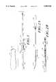
- FIG. 1is an exploded perspective view of the suture anchor assembly and kit of the present invention
- FIG. 2Ais a side elevational view of the suture anchor, the suture threading loop, the elongated gripping member, and the elongated sheath;
- FIG. 2Bis a detail view of the suture threading loop and the elongated gripping member installed in the elongated sheath;
- FIG. 3Ais a perspective view of the suture threading loop and elongated gripping member
- FIG. 3Bis a side elevational view of the suture anchor in an anchor protecting sleeve, with the suture threading loop attached to an elongated gripping member and disposed within the eyelet of the anchor;
- FIG. 3Cis a side elevational view of the suture anchor in an anchor protecting sleeve, with the suture threading loop attached to an elongated gripping member and disposed within the eyelet of the anchor and also within an elongated sheath;
- FIG. 4Ais an axial view of a bone-cutting drive bit which is engageable with the first end of the cannulated shaft;
- FIG. 4Bis an exploded side elevational view of the bone-cutting drive bit of FIG. 4A and the cannulated shaft;
- FIG. 4Cis another side elevational view of the bit of FIG. 4A;
- FIG. 4Dis a detail view of the projection fingers of the bone-cutting drive bit illustrated in FIG. 4C;
- FIG. 5is a sectional view of the cannulated driver of FIG. 4B along section lines A--A, including the anchor extractor member as it attaches to the second end of the cannulated driver shaft;
- FIG. 6is a sectional view of the anchor extraction member of FIG. 5 along section lines B--B;
- FIG. 7Ais an axial view of the handle
- FIG. 7Bis a side elevational view of the handle
- FIG. 7Cis a sectional view of the handle of FIG. 7B along section lines C--C;
- FIG. 8Ais an axial view of an anti-rotation sleeve which fits over the shaft of the driver and within the handle, as illustrated in FIG. 1;
- FIG. 8Bis a sectional view of the anti-rotation sleeve of FIG. 8A along section lines D--D;
- FIG. 9Ais an axial view of a first end of an annular element which fits over the cannulated driver shaft and is engageable with the elongated sheath;
- FIG. 9Bis a sectional view of the annular element of FIG. 9A along section lines E--E;
- FIG. 9Cis an axial view of an opposite end of the annular element.
- FIG. 1The self-threading suture anchor assembly and kit of the present invention are illustrated in FIG. 1, and the components of the assembly and kit are shown in greater detail in FIGS. 2-9C.
- the assemblycomprises a suture anchor 10, an elongated suture threading loop 12 (shown in FIGS. 2B and 3A-3B), and an elongated gripping member 14 (shown in FIGS. 2A-2B and 3A-3C) attached to the suture threading loop.
- the suture anchor 10is of a type known in the art which extends along a principal axis X between an anchor portion 10A at one end and a drive portion 10B at an opposite end, as shown in phantom in FIGS. 3B-3C.
- the suture anchor 10is threaded along at least a portion of its length or otherwise adapted for secure engagement in bone and includes an eyelet 16 in the drive end 10B.
- the eyelet 16is sufficiently large and suitably finished to accommodate one or more lengths of a suture or sections of soft tissue.
- the suture anchor 10is threaded over the entire length of the outside surface of the anchor from the anchor portion 10A to the drive portion 10B, as shown in FIGS. 3B-3C.
- the eyelet 16 of the illustrated suture anchoris the so-called "inverted" type which extends transversely through the body of the suture anchor near the drive end 10B of the anchor.
- the anchor 10includes a pair of flat regions 11 extending on either side of the eyelet 16 in a direction parallel to the principal axis X of the anchor.
- the flat regions 11permit a two-prong rotatable driver or extractor member to engage with the drive end 10B of the anchor, as detailed more fully below.
- the suture threading loop 12shown in FIG. 3A, extends from two proximate ends 12A and 12B and is disposed around a central void region 18.
- the loopincludes two substantially parallel leg portions 20 which extend from the void region 18 to the gripping member 14.
- the gripping member 14is an elongated, substantially rigid member which is secured to, and extends from, a point at or near the proximal ends of the loop 12, such as by a crimp or spot weld 22.
- the loop 12is positionable alongside the rigid gripping member 14, as shown in FIGS. 3B-3C, so that an elongated tubular sheath 24 can be disposed around, and frictionally engage with, both the loop 12 and the gripping member 14.
- the gripping member 14acts as a wand to direct and manipulate the suture threading loop 12, which is pre-loaded into the eyelet 16 of the suture anchor 10 prior to installation of the suture anchor 10 into a bone.
- the gripping member 14is elongated to facilitate handling of the suture threading loop and suture anchor and to bring the suture threading loop outside of the patient's body so that a suture can be relatively easily threaded through it and the eyelet of the suture anchor from outside of the patient's body.
- the elongated sheath 24When installed over the suture threading loop 12 and the elongated gripping member 14, the elongated sheath 24 preferably extends from a point near the proximal ends 12A, 12B of the loop to a point beyond the loop and the distal end 14A of the gripping member 14, as shown in FIGS. 2A-2B.
- the elongated sheath 24is preferably made of a flexible, lightweight material, such as plastic, with a diameter which is sufficiently large to enclose the threading loop and elongated gripping member as they are disposed alongside one another without severely restricting movement of the sheath relative to the threading loop and gripping member.
- a portion of the sheath 24is compressed about the gripping member 14 and suture threading loop 12 therein, such as by controlled application of local heating to the sheath 24 with a heat gun, to establish frictional engagement between the sheath 24 and the gripping member 14 and threading loop 12.
- this frictional engagement of the sheath with the gripper and threading loopprevents premature disengagement of the sheath 24 from the gripper 14 and threading loop 12.
- the end portion 24A of the elongated sheath 24which extends beyond the loop 12 and gripping member 14 extends through an opening in a sidewall of a cannulated driver and is engageable with the driver at that end so that removal of the driver from the suture anchor after the anchor is installed effects a simultaneous removal of the elongated sheath, thereby exposing the suture threading loop and gripping member in preparation for threading of the suture anchor.
- Axial withdrawal of the driver from the suture anchor after the suture anchor is installedtypically provides sufficient axial force to overcome the frictional engagement established between the sheath 24 and the gripping member 14 and threading loop 12 therein, so that the sheath can be removed with the driver.
- the loop 12is preferably made of a resilient material, such as a wire, which is sufficiently rigid to maintain a loop shape even when the loop is temporarily collapsed or is otherwise partially flattened to fit alongside the gripping member 14 and/or within the elongated sheath 24.
- a resilient materialsuch as a wire
- stainless steelis used as the material for the loop, although other materials meeting the above-described requirements are within the scope of the invention.
- an anchor protector 26can be inserted over the anchor portion 10A of the suture anchor 10 to facilitate handling of the anchor, which may relatively small and difficult to grasp without forceps, and to protect both the anchor portion 10A and anything which may come into contact with the anchor portion 10A prior to installation of the anchor into bone.
- the anchor protector 26can be, for example, a sleeve of flexible or rigid tubing, such as plastic tubing, which slips over and frictionally engages with at least the anchor portion 10A of the anchor.
- the anchor protector 26extends beyond the end of the anchor portion 10A for a sufficient length to facilitate handling of the anchor, as shown in FIG. 2A.
- the anchor protector 26is designed for removable engagement with the suture anchor 10 and is retained on the suture anchor until just prior to installation of the anchor into bone.
- the kit shown in FIG. 1includes the suture anchor threading assembly described above, and a rotatable cannulated driver 28.
- the driver 28, shown in greater detail in FIGS. 4B and 5,comprises a cannulated shaft 30 extending along a principal axis Y between a first end 30A and a second end 30B.
- the first end 30A of the cannulated shaftis removably engageable with the drive end 10B of the suture anchor 10.
- the first end 30A of the cannulated shaft 30is adapted to receive a bone-cutting drive bit 32, shown in FIGS. 4A-4D.
- the bit 32includes two prong-like projections 34 which engage with the flat portions 11 of the suture anchor 10 to enable the anchor to be rotated and thus turned into or out of an installation site in a bone.
- the projections 34are preferably chamfered or otherwise provided with sharpened bone-cutting edges to facilitate the formation of a countersunk hole in the bone for installation of the anchor into the bone.
- each projection 34includes a 5 degree chamfer. The chamfers preferably extend in opposite directions, as shown in FIGS. 4C-4D, to facilitate entry of the bit 32 into the bone as the driver and bit are rotated.
- the bone-cutting drive bit 32is preferably permanently attached to the driver shaft, such as by laser welding.
- the bitcan be removably attached to the driver shaft, such as with an interference fit or removable locking pins.
- the cannulated shaft 30 of the driver 28includes a central canal 36, shown in FIG. 5, which is sufficiently large to permit passage therethrough of the elongated sheath 24 containing the suture threading loop 12 and the elongated gripping member 14.
- a port 38 located in a sidewall of the cannulated shaft 30provides an exit aperture through which a distal end 24A of the elongated sheath 24 passes.
- the port 38is located at a distance from the first end 30A of the cannulated shaft 30 which is less than the length of the elongated sheath 24.
- the distal end portion 24A of the sheath 24extends through the port 38 and can engage frictionally with an annular element 48 which is disposed around the cannulated shaft 30, as shown in FIG. 1 and in greater detail in FIGS. 9A-9C.
- the annular element 48can be made of, for example, plastic or other lightweight material and includes a variable-height recess 50 along one side of its inner diameter, as shown in FIGS. 9B-9C.
- variable-height recess 50is sufficiently large to permit the distal end 24A of the elongated sheath 24 to be held frictionally within the annular element 48 and against the outside of the cannulated shaft 30 without crushing or otherwise damaging the elongated sheath 24.
- the annular element 48is slidable along a portion of the cannulated shaft 30 in the direction of arrows 42 in FIG. 1 for selective engagement with the distal end 24A of the elongated sheath 24.
- a handle 44is adapted for releasable engagement with the second end 30B of the driver 28, as shown in FIG. 1 and in greater detail in FIGS. 7A-7C.
- the handle 44includes a central void region 45 extending axially therethrough to accommodate a portion of the shaft 30.
- the handle 44is preferably constructed of a lightweight material, such as plastic, and preferably is adapted to receivingly engage with an anti-rotation sleeve element 46, shown in FIGS. 1 and 8A-8B, which is insertable into an opening in the handle and is adapted for frictional engagement with the cannulated shaft 30 of the driver 28.
- the anti-rotation sleeve element 46has a triangular cross-section, as shown in FIG.
- the second end 30B of the cannulated shaft 30fits within the void region 45 of the handle 44, as shown in FIGS. 1 and 7C.
- the driver 28can be easily inserted into the handle by pushing it axially into the void region 45 and adjusting the position of the anti-rotation sleeve element 46 along the driver shaft 30 until the sleeve element 46 engages with the correspondingly-shaped opening 47 in the handle.
- the driver 28can be easily removed from the handle 44 by pulling it axially from the handle until the sleeve element 46 releases from the handle.
- the kitcan further include an anchor extractor member 52, shown in FIGS. 1, 5 and 6, which is disposed at the second end 30B of the cannulated shaft 30 of the driver 28.
- the anchor extractor member 52is adapted for releasable engagement with the drive end 10B of the suture anchor 10 and is designed to facilitate removal of the suture anchor from its installation site in a bone.
- the anchor extractor member 52extends along a principal axis Z and includes a through hole 54 near a proximal end 52A thereof.
- a corresponding through hole 56is located in the shaft 30 of the driver 28.
- the through holes 54, 56are adapted to receive a pin for securing the anchor extractor member 48 within the shaft 30.
- the distal tip 52A of the anchor extractor member 52includes a pair of fingerlike projections 58 which extend into and engage with the flat regions 11 near the eyelet 16 of the anchor 10. Counterclockwise rotation of the extractor member 52 in the drive end of the suture anchor 10 which has been installed into a bone disengages the anchor from the bone and permits it to be loosened or removed.
- the anchor extractor member 52includes a wedge-shaped end 39 which can act as a guide for the end of the elongated sheath 24 (indicated by dashed line 41 in FIG. 5) to facilitate its passage through the port 38.
- the anchor extractor member 52is adapted to fit within the void region 45 of the handle 44 in the same manner in which as the drive bit end of the driver 28 fits within the handle.
- the driver 28can include a bone-cutting drive bit 32 at one end 30A and an anchor extractor member 52 at an opposite end 30B, and either end of the driver 28 can be engaged securely with the handle 44.
- the shaft 30preferably includes a flat region 49 at the location of the anti-rotation sleeve element 46 which permits the axial position of the anti-rotation sleeve to be varied along the shaft.
- the anti-rotation sleeve 46can be moved axially along the length of the flat region 49 to locate it in the desired position on the shaft to secure the driver shaft within the handle.
- the driver and extractor member, as well as the suture threading loop,are all made in a variety of sizes to accommodate the various sizes of suture anchor which are used in surgical procedures.
- a suture anchorcan be conveniently installed into a bone and threaded with a suture or a section of tendon or other soft tissue after installation according to the following method.
- a suture anchor of the appropriate sizeis selected.
- the suture anchormay be provided with an anchor protector already installed on it to protect the anchor and facilitate its handling.
- a corresponding driver and extractor member which will fit the suture anchorare then selected.
- An anti-rotation sleeve and an annular elementare disposed around the driver shaft.
- a handle which is suitable for engaging the driver shaft and extractor memberis then selected.
- the handleis assembled to the driver shaft by sliding the handle over the driver shaft and aligning the anti-rotation sleeve on the shaft with the corresponding opening in the handle, with the cutting drive bit end of the driver exposed and the anchor extractor member, if provided, disposed within the interior of the handle.
- the suture threading loopmay be flattened and caused to extend alongside the elongated gripping member. Both the loop and the gripping member are then inserted into the elongated sheath, the distal end of which extends for approximately an inch beyond the ends of the loop and gripping member within the sheath.
- the sheathis controllably compressed about a portion of the gripping member and threading loop therein to establish a frictional engagement between the sheath and those elements inside the sheath.
- the preloaded suture anchoris then assembled to the driver by holding the anchor protector and inserting the suture threading loop, the attached elongated gripping member and the elongated sheath surrounding them into the cannulated shaft from the drive bit end.
- the flat regions of the suture anchorare then aligned with the fingerlike projections on the bone-cutting drive bit to engage and fully seat the anchor with the bit.
- the distal end portion of the elongated sheath containing the suture threading loop and elongated gripping membershould extend through the port in the cannulated shaft.
- the annular elementcan then be slid over the distal portion of the sheath to engage it against the shaft. This operation also secures the suture anchor to the driver.
- the anchor protectorcan now be removed from the anchor by twisting it off of the anchor, in preparation for installation of the anchor into a bone.
- the tip of the anchoris then placed substantially perpendicular to the bone into which it is to be installed.
- the driveris rotated clockwise by the handle with application of constant axial pressure. Care should be taken to keep the anchor perpendicular to the bone to prevent premature dissociation of the anchor from the driver.
- the driveris rotated in a clockwise direction until the anchor disengages from the cutting bit and is fully installed into the bone. After disengagement, the driver can be pulled away from the anchor, thereby removing the elongated sheath and exposing the suture threading loop and elongated gripping member. The elongated sheath will be retained with the driver shaft and annular element and can be discarded. The driver can be reused to install another suture anchor.
- a suture or section of soft tissuesuch as a tendon
- a suture or section of soft tissuecan be threaded through the eyelet of the installed anchor by inserting the suture or soft tissue section through the threading loop and then pulling the elongated gripping member and attached threading loop through the eyelet.
- the suture or soft tissue sectionwill be pulled through the eyelet with the threading loop. Care should be taken to provide a sufficient length of suture or soft tissue section so that the anchor can be threaded properly.
- the suture threading loop and elongated gripping membercan be discarded after the suture or soft tissue section is threaded through the eyelet of the anchor.
- the driver shaftis removed from the handle and reversed to expose the anchor extractor member.
- the driveris then reassembled to the handle with the anchor extractor member exposed for operation.
- the anti-rotation sleeveis positioned in the desired axial location along the shaft to ensure secure engagement of the shaft in the handle.
Landscapes
- Health & Medical Sciences (AREA)
- Surgery (AREA)
- Life Sciences & Earth Sciences (AREA)
- Biomedical Technology (AREA)
- Nuclear Medicine, Radiotherapy & Molecular Imaging (AREA)
- Engineering & Computer Science (AREA)
- Heart & Thoracic Surgery (AREA)
- Medical Informatics (AREA)
- Molecular Biology (AREA)
- Animal Behavior & Ethology (AREA)
- General Health & Medical Sciences (AREA)
- Public Health (AREA)
- Veterinary Medicine (AREA)
- Rheumatology (AREA)
- Surgical Instruments (AREA)
Abstract
Description
Claims (14)
Priority Applications (1)
| Application Number | Priority Date | Filing Date | Title |
|---|---|---|---|
| US08/799,120US5899920A (en) | 1997-02-11 | 1997-02-11 | Suture anchor assembly and kit |
Applications Claiming Priority (1)
| Application Number | Priority Date | Filing Date | Title |
|---|---|---|---|
| US08/799,120US5899920A (en) | 1997-02-11 | 1997-02-11 | Suture anchor assembly and kit |
Publications (1)
| Publication Number | Publication Date |
|---|---|
| US5899920Atrue US5899920A (en) | 1999-05-04 |
Family
ID=25175083
Family Applications (1)
| Application Number | Title | Priority Date | Filing Date |
|---|---|---|---|
| US08/799,120Expired - Fee RelatedUS5899920A (en) | 1997-02-11 | 1997-02-11 | Suture anchor assembly and kit |
Country Status (1)
| Country | Link |
|---|---|
| US (1) | US5899920A (en) |
Cited By (127)
| Publication number | Priority date | Publication date | Assignee | Title |
|---|---|---|---|---|
| US6267766B1 (en) | 1999-05-28 | 2001-07-31 | Stephen S. Burkhart | Suture anchor reel device kit and method |
| US20020002369A1 (en)* | 1993-08-23 | 2002-01-03 | Hood Larry L. | Method and apparatus for modifying visual acuity by moving a focal point of energy within a cornea |
| US20020052629A1 (en)* | 2000-09-12 | 2002-05-02 | Morgan Daniel E. | Apparatus and method for securing suture to bone |
| WO2002021997A3 (en)* | 2000-09-12 | 2002-06-27 | Axya Medical Inc | Apparatus and method for securing suture to bone |
| US6508830B2 (en)* | 2001-04-30 | 2003-01-21 | Musculoskeletal Transplant Foundation | Suture anchor |
| US20030088272A1 (en)* | 2001-11-08 | 2003-05-08 | Graham Smith | Tissue repair system |
| US20030093119A1 (en)* | 2001-09-27 | 2003-05-15 | Chunfeng Zhao | Eyelet reinforcement at the tissue-suture interface |
| US20030120309A1 (en)* | 2001-11-08 | 2003-06-26 | Dennis Colleran | Reattachment of tissue to base tissue |
| US20030181903A1 (en)* | 1993-08-23 | 2003-09-25 | Hood Larry L. | Method and apparatus for modifications of visual acuity by thermal means |
| US6673069B1 (en)* | 2000-03-30 | 2004-01-06 | Refractec, Inc. | Thermokeratoplasty system with a power supply that can determine a wet or dry cornea |
| US6723093B2 (en) | 2002-03-22 | 2004-04-20 | Refractec Inc. | Electrode assembly for a thermokeratoplasty system used to correct vision acuity |
| US20050251205A1 (en)* | 2004-05-07 | 2005-11-10 | Usgi Medical Inc. | Apparatus and methods for positioning and securing anchors |
| US20050277966A1 (en)* | 2004-06-09 | 2005-12-15 | Usgi Medical Inc. | Compressible tissue anchor assemblies |
| US20050277983A1 (en)* | 2004-06-09 | 2005-12-15 | Usgi Medical Inc. | System for optimizing anchoring force |
| US20050277981A1 (en)* | 2004-06-09 | 2005-12-15 | Usgi Medical Inc. | Apparatus and methods for optimizing anchoring force |
| US20060106423A1 (en)* | 2004-09-28 | 2006-05-18 | Thomas Weisel | Suture anchor |
| US20060217762A1 (en)* | 2004-06-09 | 2006-09-28 | Usgi Medical, Inc. | Compressible tissue anchor assemblies |
| US20070135816A1 (en)* | 2005-11-21 | 2007-06-14 | Ist Innovative Shoulder Technology Ag | Bone anchor |
| US20070142861A1 (en)* | 2003-03-31 | 2007-06-21 | Burkhart Stephen S | Suture anchor device, kit and method |
| US7347863B2 (en) | 2004-05-07 | 2008-03-25 | Usgi Medical, Inc. | Apparatus and methods for manipulating and securing tissue |
| US7361180B2 (en) | 2004-05-07 | 2008-04-22 | Usgi Medical, Inc. | Apparatus for manipulating and securing tissue |
| US20080109038A1 (en)* | 2006-11-08 | 2008-05-08 | Musculoskeletal Transplant Foundation | Threaded suture anchor and inserter device |
| US7390329B2 (en) | 2004-05-07 | 2008-06-24 | Usgi Medical, Inc. | Methods for grasping and cinching tissue anchors |
| US20080184297A1 (en)* | 2001-02-21 | 2008-07-31 | Ellis Michael D | Systems and methods for interactive program guides with personal video recording features |
| US7416554B2 (en) | 2002-12-11 | 2008-08-26 | Usgi Medical Inc | Apparatus and methods for forming and securing gastrointestinal tissue folds |
| US7571729B2 (en) | 2004-03-09 | 2009-08-11 | Usgi Medical, Inc. | Apparatus and methods for performing mucosectomy |
| US7601159B2 (en) | 2004-05-07 | 2009-10-13 | Usgi Medical, Inc. | Interlocking tissue anchor apparatus and methods |
| US7618426B2 (en) | 2002-12-11 | 2009-11-17 | Usgi Medical, Inc. | Apparatus and methods for forming gastrointestinal tissue approximations |
| US7704264B2 (en) | 1999-06-25 | 2010-04-27 | Usgi Medical, Inc. | Apparatus and methods for forming and securing gastrointestinal tissue folds |
| WO2010028324A3 (en)* | 2008-09-08 | 2010-05-27 | Revolutionary Surgical Device, Llc | Knotless suture anchors |
| US20100130990A1 (en)* | 2007-07-03 | 2010-05-27 | Saliman Justin D | Methods of suturing and repairing tissue using a continuous suture passer device |
| US7736374B2 (en) | 2004-05-07 | 2010-06-15 | Usgi Medical, Inc. | Tissue manipulation and securement system |
| US20100305576A1 (en)* | 2009-05-29 | 2010-12-02 | Wright Medical Technology, Inc. | Suture anchoring instrument |
| US20100313213A1 (en)* | 1998-07-14 | 2010-12-09 | United Video Properties, Inc. | Client-server based interactive television program guide system with remote server recording |
| US20100316350A1 (en)* | 1998-09-17 | 2010-12-16 | United Video Properties, Inc. | Program guide with a digital storage device |
| US7918869B2 (en) | 2004-05-07 | 2011-04-05 | Usgi Medical, Inc. | Methods and apparatus for performing endoluminal gastroplasty |
| US7918845B2 (en) | 2003-01-15 | 2011-04-05 | Usgi Medical, Inc. | Endoluminal tool deployment system |
| US20110087246A1 (en)* | 2007-07-03 | 2011-04-14 | Saliman Justin D | Methods and devices for continuous suture passing |
| US20110112556A1 (en)* | 2009-11-09 | 2011-05-12 | Saliman Justin D | Devices, systems and methods for meniscus repair |
| US7942898B2 (en) | 2002-12-11 | 2011-05-17 | Usgi Medical, Inc. | Delivery systems and methods for gastric reduction |
| US7942884B2 (en) | 2002-12-11 | 2011-05-17 | Usgi Medical, Inc. | Methods for reduction of a gastric lumen |
| US20110130773A1 (en)* | 2007-07-03 | 2011-06-02 | Saliman Justin D | Methods for continuous suture passing |
| US20110152892A1 (en)* | 2007-11-05 | 2011-06-23 | Saliman Justin D | Suture passing instrument and method |
| US20110225616A1 (en)* | 2003-01-30 | 2011-09-15 | United Video Properties, Inc. | Interactive television systems with digital video recording and adjustable reminders |
| US8128698B2 (en) | 1999-10-20 | 2012-03-06 | Anulex Technologies, Inc. | Method and apparatus for the treatment of the intervertebral disc annulus |
| US8163022B2 (en) | 2008-10-14 | 2012-04-24 | Anulex Technologies, Inc. | Method and apparatus for the treatment of the intervertebral disc annulus |
| US8216252B2 (en) | 2004-05-07 | 2012-07-10 | Usgi Medical, Inc. | Tissue manipulation and securement system |
| US8257394B2 (en) | 2004-05-07 | 2012-09-04 | Usgi Medical, Inc. | Apparatus and methods for positioning and securing anchors |
| US8298291B2 (en) | 2005-05-26 | 2012-10-30 | Usgi Medical, Inc. | Methods and apparatus for securing and deploying tissue anchors |
| US8444657B2 (en) | 2004-05-07 | 2013-05-21 | Usgi Medical, Inc. | Apparatus and methods for rapid deployment of tissue anchors |
| US8460319B2 (en) | 2010-01-11 | 2013-06-11 | Anulex Technologies, Inc. | Intervertebral disc annulus repair system and method |
| US8465505B2 (en) | 2011-05-06 | 2013-06-18 | Ceterix Orthopaedics, Inc. | Suture passer devices and methods |
| US8500809B2 (en) | 2011-01-10 | 2013-08-06 | Ceterix Orthopaedics, Inc. | Implant and method for repair of the anterior cruciate ligament |
| US8545535B2 (en) | 2009-05-12 | 2013-10-01 | Foundry Newco Xi, Inc. | Suture anchors with one-way cinching mechanisms |
| US8556977B2 (en) | 1999-10-20 | 2013-10-15 | Anulex Technologies, Inc. | Tissue anchoring system and method |
| US8663253B2 (en) | 2007-07-03 | 2014-03-04 | Ceterix Orthopaedics, Inc. | Methods of meniscus repair |
| US8702731B2 (en) | 2007-07-03 | 2014-04-22 | Ceterix Orthopaedics, Inc. | Suturing and repairing tissue using in vivo suture loading |
| US8726909B2 (en) | 2006-01-27 | 2014-05-20 | Usgi Medical, Inc. | Methods and apparatus for revision of obesity procedures |
| US8790370B2 (en) | 2012-03-30 | 2014-07-29 | Depuy Mitek, Llc | Surgical filament assemblies |
| US8806533B1 (en) | 2004-10-08 | 2014-08-12 | United Video Properties, Inc. | System and method for using television information codes |
| US8814905B2 (en) | 2010-11-23 | 2014-08-26 | Depuy Mitek, Llc | Surgical filament snare assemblies |
| US8821545B2 (en) | 2010-11-23 | 2014-09-02 | Depuy Mitek, Llc | Surgical filament snare assemblies |
| US8821543B2 (en) | 2010-12-23 | 2014-09-02 | Depuy Mitek, Llc | Adjustable anchor systems and methods |
| US20140257385A1 (en)* | 2013-03-06 | 2014-09-11 | Smith & Nephew, Inc. | Microanchor |
| US8870916B2 (en) | 2006-07-07 | 2014-10-28 | USGI Medical, Inc | Low profile tissue anchors, tissue anchor systems, and methods for their delivery and use |
| US8894684B2 (en) | 2012-05-07 | 2014-11-25 | Medos International Sàrl | Systems, devices, and methods for securing tissue using a suture having one or more protrusions |
| US9060764B2 (en) | 2012-05-07 | 2015-06-23 | Medos International Sàrl | Systems, devices, and methods for securing tissue |
| US9060763B2 (en) | 2012-05-07 | 2015-06-23 | Medos International Sàrl | Systems, devices, and methods for securing tissue |
| US9075861B2 (en) | 2006-03-06 | 2015-07-07 | Veveo, Inc. | Methods and systems for segmenting relative user preferences into fine-grain and coarse-grain collections |
| US9095331B2 (en) | 2010-12-23 | 2015-08-04 | Medos International Sàrl | Adjustable anchor systems and methods |
| US9095442B2 (en) | 1999-10-20 | 2015-08-04 | Krt Investors, Inc. | Method and apparatus for the treatment of the intervertebral disc annulus |
| US9114025B2 (en) | 1999-10-20 | 2015-08-25 | Krt Investors, Inc. | Methods and devices for spinal disc annulus reconstruction and repair |
| US9125169B2 (en) | 2011-12-23 | 2015-09-01 | Rovi Guides, Inc. | Methods and systems for performing actions based on location-based rules |
| US9166714B2 (en) | 2009-09-11 | 2015-10-20 | Veveo, Inc. | Method of and system for presenting enriched video viewing analytics |
| WO2015164570A1 (en)* | 2014-04-25 | 2015-10-29 | DePuy Synthes Products, Inc. | Flexible suture anchor threader and suture anchor kit |
| US9179907B2 (en) | 2000-06-22 | 2015-11-10 | Arthrex, Inc. | Knotless graft fixation assembly |
| US9191722B2 (en) | 1997-07-21 | 2015-11-17 | Rovi Guides, Inc. | System and method for modifying advertisement responsive to EPG information |
| US9192373B2 (en) | 2012-12-27 | 2015-11-24 | Medos International Sàrl | Surgical constructs and methods for securing tissue |
| US9265514B2 (en) | 2012-04-17 | 2016-02-23 | Miteas Ltd. | Manipulator for grasping tissue |
| US9294799B2 (en) | 2000-10-11 | 2016-03-22 | Rovi Guides, Inc. | Systems and methods for providing storage of data on servers in an on-demand media delivery system |
| US9319735B2 (en) | 1995-06-07 | 2016-04-19 | Rovi Guides, Inc. | Electronic television program guide schedule system and method with data feed access |
| US9326025B2 (en) | 2007-03-09 | 2016-04-26 | Rovi Technologies Corporation | Media content search results ranked by popularity |
| US9345567B2 (en) | 2012-05-07 | 2016-05-24 | Medos International Sàrl | Systems, devices, and methods for securing tissue using snare assemblies and soft anchors |
| US9426509B2 (en) | 1998-08-21 | 2016-08-23 | Rovi Guides, Inc. | Client-server electronic program guide |
| US9463010B2 (en) | 2009-05-12 | 2016-10-11 | The Foundry, Llc | Methods and devices to treat diseased or injured musculoskeletal tissue |
| US9521999B2 (en) | 2005-09-13 | 2016-12-20 | Arthrex, Inc. | Fully-threaded bioabsorbable suture anchor |
| US9526493B2 (en) | 1999-02-02 | 2016-12-27 | Arthrex, Inc. | Suture anchor with insert-molded rigid member |
| US20160374661A1 (en)* | 2009-10-28 | 2016-12-29 | Smith & Nephew, Inc. | Threaded suture anchor |
| US9585651B2 (en) | 2005-05-26 | 2017-03-07 | Usgi Medical, Inc. | Methods and apparatus for securing and deploying tissue anchors |
| US9622739B2 (en) | 2004-04-06 | 2017-04-18 | Arthrex, Inc. | Suture anchor |
| US9700299B2 (en) | 2011-05-06 | 2017-07-11 | Ceterix Orthopaedics, Inc. | Suture passer devices and methods |
| US9736524B2 (en) | 2011-01-06 | 2017-08-15 | Veveo, Inc. | Methods of and systems for content search based on environment sampling |
| US9737294B2 (en) | 2013-01-28 | 2017-08-22 | Cartiva, Inc. | Method and system for orthopedic repair |
| US9737293B2 (en) | 2013-03-15 | 2017-08-22 | Medos International Sàrl | Surgical constructs with collapsing suture loop and methods for securing tissue |
| US9749693B2 (en) | 2006-03-24 | 2017-08-29 | Rovi Guides, Inc. | Interactive media guidance application with intelligent navigation and display features |
| US9763655B2 (en) | 2012-09-20 | 2017-09-19 | Medos International Sarl | Systems, devices, and methods for securing tissue using hard anchors |
| US10063934B2 (en) | 2008-11-25 | 2018-08-28 | Rovi Technologies Corporation | Reducing unicast session duration with restart TV |
| US20180303475A1 (en)* | 2012-12-27 | 2018-10-25 | Medos International Sarl | Multi-Piece Anchor Inserter |
| US10179012B2 (en) | 2013-01-28 | 2019-01-15 | Cartiva, Inc. | Systems and methods for orthopedic repair |
| US10383624B2 (en) | 2008-10-24 | 2019-08-20 | The Foundry, Llc | Methods and devices for suture anchor delivery |
| US10973507B2 (en) | 2006-02-03 | 2021-04-13 | Biomet Sports Medicine, Llc | Method and apparatus for coupling soft tissue to a bone |
| US10987099B2 (en)* | 2006-02-03 | 2021-04-27 | Biomet Sports Medicine, Llc | Method for tissue fixation |
| US11039826B2 (en) | 2006-02-03 | 2021-06-22 | Biomet Sports Medicine, Llc | Method and apparatus for forming a self-locking adjustable loop |
| US11065103B2 (en) | 2006-02-03 | 2021-07-20 | Biomet Sports Medicine, Llc | Method and apparatus for fixation of an ACL graft |
| US11096684B2 (en) | 2006-09-29 | 2021-08-24 | Biomet Sports Medicine, Llc | Method and apparatus for forming a self-locking adjustable loop |
| US11109857B2 (en) | 2004-11-05 | 2021-09-07 | Biomet Sports Medicine, Llc | Soft tissue repair device and method |
| US11116495B2 (en) | 2006-02-03 | 2021-09-14 | Biomet Sports Medicine, Llc | Soft tissue repair assembly and associated method |
| US11185320B2 (en) | 2007-04-10 | 2021-11-30 | Biomet Sports Medicine, Llc | Adjustable knotless loops |
| US11241305B2 (en) | 2011-11-03 | 2022-02-08 | Biomet Sports Medicine, Llc | Method and apparatus for stitching tendons |
| US11259792B2 (en) | 2006-02-03 | 2022-03-01 | Biomet Sports Medicine, Llc | Method and apparatus for coupling anatomical features |
| US11259794B2 (en) | 2006-09-29 | 2022-03-01 | Biomet Sports Medicine, Llc | Method for implanting soft tissue |
| US11284884B2 (en) | 2006-02-03 | 2022-03-29 | Biomet Sports Medicine, Llc | Method and apparatus for coupling soft tissue to a bone |
| US11311287B2 (en) | 2006-02-03 | 2022-04-26 | Biomet Sports Medicine, Llc | Method for tissue fixation |
| US11317907B2 (en) | 2006-02-03 | 2022-05-03 | Biomet Sports Medicine, Llc | Method and apparatus for forming a self-locking adjustable loop |
| US11376115B2 (en) | 2006-09-29 | 2022-07-05 | Biomet Sports Medicine, Llc | Prosthetic ligament system for knee joint |
| US11471147B2 (en) | 2006-02-03 | 2022-10-18 | Biomet Sports Medicine, Llc | Method and apparatus for coupling soft tissue to a bone |
| US11534157B2 (en) | 2011-11-10 | 2022-12-27 | Biomet Sports Medicine, Llc | Method for coupling soft tissue to a bone |
| US11589859B2 (en) | 2006-02-03 | 2023-02-28 | Biomet Sports Medicine, Llc | Method and apparatus for coupling soft tissue to bone |
| US11607323B2 (en) | 2018-10-15 | 2023-03-21 | Howmedica Osteonics Corp. | Patellofemoral trial extractor |
| US11612391B2 (en) | 2007-01-16 | 2023-03-28 | Biomet Sports Medicine, Llc | Soft tissue repair device and associated methods |
| US11617572B2 (en) | 2006-02-03 | 2023-04-04 | Biomet Sports Medicine, Llc | Soft tissue repair device and associated methods |
| US11723648B2 (en) | 2006-02-03 | 2023-08-15 | Biomet Sports Medicine, Llc | Method and apparatus for soft tissue fixation |
| US11998188B2 (en) | 2020-12-28 | 2024-06-04 | DePuy Synthes Products, Inc. | Suture threader for bone plate |
| US12096928B2 (en) | 2009-05-29 | 2024-09-24 | Biomet Sports Medicine, Llc | Method and apparatus for coupling soft tissue to a bone |
| US12245759B2 (en) | 2008-08-22 | 2025-03-11 | Biomet Sports Medicine, Llc | Method and apparatus for coupling soft tissue to bone |
| US12329373B2 (en) | 2011-05-02 | 2025-06-17 | Biomet Sports Medicine, Llc | Method and apparatus for soft tissue fixation |
| US12419632B2 (en) | 2008-08-22 | 2025-09-23 | Biomet Sports Medicine, Llc | Method and apparatus for coupling anatomical features |
Citations (5)
| Publication number | Priority date | Publication date | Assignee | Title |
|---|---|---|---|---|
| US4632100A (en)* | 1985-08-29 | 1986-12-30 | Marlowe E. Goble | Suture anchor assembly |
| US5224946A (en)* | 1990-07-02 | 1993-07-06 | American Cyanamid Company | Bone anchor and method of anchoring a suture to a bone |
| US5466243A (en)* | 1994-02-17 | 1995-11-14 | Arthrex, Inc. | Method and apparatus for installing a suture anchor through a hollow cannulated grasper |
| US5534011A (en)* | 1994-10-27 | 1996-07-09 | Vesica Medical, Inc. | Method and apparatus for threading a suture anchor |
| US5591207A (en)* | 1995-03-30 | 1997-01-07 | Linvatec Corporation | Driving system for inserting threaded suture anchors |
- 1997
- 1997-02-11USUS08/799,120patent/US5899920A/ennot_activeExpired - Fee Related
Patent Citations (5)
| Publication number | Priority date | Publication date | Assignee | Title |
|---|---|---|---|---|
| US4632100A (en)* | 1985-08-29 | 1986-12-30 | Marlowe E. Goble | Suture anchor assembly |
| US5224946A (en)* | 1990-07-02 | 1993-07-06 | American Cyanamid Company | Bone anchor and method of anchoring a suture to a bone |
| US5466243A (en)* | 1994-02-17 | 1995-11-14 | Arthrex, Inc. | Method and apparatus for installing a suture anchor through a hollow cannulated grasper |
| US5534011A (en)* | 1994-10-27 | 1996-07-09 | Vesica Medical, Inc. | Method and apparatus for threading a suture anchor |
| US5591207A (en)* | 1995-03-30 | 1997-01-07 | Linvatec Corporation | Driving system for inserting threaded suture anchors |
Non-Patent Citations (8)
| Title |
|---|
| "Statak™ Soft Tissue Attachment Device", Zimmer, 1994. |
| Bradley, "The Anchor That Holds Fast", Linvatec, 1994. |
| Bradley, The Anchor That Holds Fast , Linvatec , 1994.* |
| Ogden, "A New Bone Anchor for Re-Attachment of Soft Tissue and Management of Fractures and Dislocations" Orthopedic Surgery, Surgical Technology International III, pp. 593-602, Oct., 1994. |
| Ogden, A New Bone Anchor for Re Attachment of Soft Tissue and Management of Fractures and Dislocations Orthopedic Surgery , Surgical Technology International III, pp. 593 602, Oct., 1994.* |
| Rosenberg, "Endoscopic Technique For ACL Reconstruction With Pro-Trac Tibial Guide", Acufex, 1991. |
| Rosenberg, Endoscopic Technique For ACL Reconstruction With Pro Trac Tibial Guide , Acufex , 1991.* |
| Statak Soft Tissue Attachment Device , Zimmer , 1994.* |
Cited By (294)
| Publication number | Priority date | Publication date | Assignee | Title |
|---|---|---|---|---|
| US20030181903A1 (en)* | 1993-08-23 | 2003-09-25 | Hood Larry L. | Method and apparatus for modifications of visual acuity by thermal means |
| US20020002369A1 (en)* | 1993-08-23 | 2002-01-03 | Hood Larry L. | Method and apparatus for modifying visual acuity by moving a focal point of energy within a cornea |
| US9319735B2 (en) | 1995-06-07 | 2016-04-19 | Rovi Guides, Inc. | Electronic television program guide schedule system and method with data feed access |
| US9191722B2 (en) | 1997-07-21 | 2015-11-17 | Rovi Guides, Inc. | System and method for modifying advertisement responsive to EPG information |
| US8272019B2 (en) | 1998-07-14 | 2012-09-18 | United Video Properties, Inc. | Client-server based interactive television program guide system with remote server recording |
| US20100319026A1 (en)* | 1998-07-14 | 2010-12-16 | United Video Properties, Inc. | Client server based interactive television program guide system with remote server recording |
| US8776126B2 (en) | 1998-07-14 | 2014-07-08 | United Video Properties, Inc. | Client-server based interactive television guide with server recording |
| US9021538B2 (en) | 1998-07-14 | 2015-04-28 | Rovi Guides, Inc. | Client-server based interactive guide with server recording |
| US20100313213A1 (en)* | 1998-07-14 | 2010-12-09 | United Video Properties, Inc. | Client-server based interactive television program guide system with remote server recording |
| US20100313221A1 (en)* | 1998-07-14 | 2010-12-09 | United Video Properties, Inc. | Client-server based interactive television program guide system with remote server recording |
| US10027998B2 (en) | 1998-07-14 | 2018-07-17 | Rovi Guides, Inc. | Systems and methods for multi-tuner recording |
| US20100313224A1 (en)* | 1998-07-14 | 2010-12-09 | United Video Properties, Inc. | Client-server based interactive television program guide system with remote server recording |
| US9232254B2 (en) | 1998-07-14 | 2016-01-05 | Rovi Guides, Inc. | Client-server based interactive television guide with server recording |
| US8528032B2 (en) | 1998-07-14 | 2013-09-03 | United Video Properties, Inc. | Client-server based interactive television program guide system with remote server recording |
| US9226006B2 (en) | 1998-07-14 | 2015-12-29 | Rovi Guides, Inc. | Client-server based interactive guide with server recording |
| US8091110B2 (en) | 1998-07-14 | 2012-01-03 | United Video Properties, Inc. | Client-server based interactive television program guide system with remote server recording |
| US10075746B2 (en) | 1998-07-14 | 2018-09-11 | Rovi Guides, Inc. | Client-server based interactive television guide with server recording |
| US9154843B2 (en) | 1998-07-14 | 2015-10-06 | Rovi Guides, Inc. | Client-server based interactive guide with server recording |
| US9118948B2 (en) | 1998-07-14 | 2015-08-25 | Rovi Guides, Inc. | Client-server based interactive guide with server recording |
| US8176521B2 (en) | 1998-07-14 | 2012-05-08 | United Video Properties, Inc. | Client server based interactive television program guide system with remote server recording |
| US8266662B2 (en) | 1998-07-14 | 2012-09-11 | United Video Properties, Inc. | Client-server based interactive television program guide system with remote server recording |
| US9055318B2 (en) | 1998-07-14 | 2015-06-09 | Rovi Guides, Inc. | Client-server based interactive guide with server storage |
| US9055319B2 (en) | 1998-07-14 | 2015-06-09 | Rovi Guides, Inc. | Interactive guide with recording |
| US9426509B2 (en) | 1998-08-21 | 2016-08-23 | Rovi Guides, Inc. | Client-server electronic program guide |
| US8843960B2 (en) | 1998-09-17 | 2014-09-23 | United Video Properties, Inc. | Electronic program guide with digital storage |
| US9106947B2 (en) | 1998-09-17 | 2015-08-11 | Rovi Guides, Inc. | Electronic program guide with digital storage |
| US9363553B2 (en) | 1998-09-17 | 2016-06-07 | Rovi Guides, Inc. | Electronic program guide with digital storage |
| US9237371B2 (en) | 1998-09-17 | 2016-01-12 | Rovi Guides, Inc. | Electronic program guide with digital storage |
| US20100316350A1 (en)* | 1998-09-17 | 2010-12-16 | United Video Properties, Inc. | Program guide with a digital storage device |
| US8448215B2 (en) | 1998-09-17 | 2013-05-21 | United Video Properties, Inc. | Electronic program guide with digital storage |
| US8413191B2 (en) | 1998-09-17 | 2013-04-02 | United Video Properties, Inc. | Program guide with a digital storage device |
| US8413193B2 (en) | 1998-09-17 | 2013-04-02 | United Video Properties, Inc. | Program guide with a digital storage device |
| US20110162011A1 (en)* | 1998-09-17 | 2011-06-30 | United Video Properties, Inc. | Program guide with a digital storage device |
| US8898721B2 (en) | 1998-09-17 | 2014-11-25 | United Video Properties, Inc. | Electronic program guide with digital storage |
| US9100686B2 (en) | 1998-09-17 | 2015-08-04 | Rovi Guides, Inc. | Electronic program guide with digital storage |
| US9549726B2 (en) | 1999-02-02 | 2017-01-24 | Arthrex, Inc. | Suture anchor with insert-molded rigid member |
| US9526493B2 (en) | 1999-02-02 | 2016-12-27 | Arthrex, Inc. | Suture anchor with insert-molded rigid member |
| US6267766B1 (en) | 1999-05-28 | 2001-07-31 | Stephen S. Burkhart | Suture anchor reel device kit and method |
| US9216017B2 (en) | 1999-05-28 | 2015-12-22 | Arthrex, Inc. | Suture anchor device, kit, and method |
| US20040172062A1 (en)* | 1999-05-28 | 2004-09-02 | Burkhart Stephen S. | Suture anchor reel device, kit and method |
| US6540750B2 (en) | 1999-05-28 | 2003-04-01 | Stephen S. Burkhart | Suture anchor reel device, kit and method |
| US7744613B2 (en) | 1999-06-25 | 2010-06-29 | Usgi Medical, Inc. | Apparatus and methods for forming and securing gastrointestinal tissue folds |
| US8343175B2 (en) | 1999-06-25 | 2013-01-01 | Usgi Medical, Inc. | Apparatus and methods for forming and securing gastrointestinal tissue folds |
| US7955340B2 (en) | 1999-06-25 | 2011-06-07 | Usgi Medical, Inc. | Apparatus and methods for forming and securing gastrointestinal tissue folds |
| US7704264B2 (en) | 1999-06-25 | 2010-04-27 | Usgi Medical, Inc. | Apparatus and methods for forming and securing gastrointestinal tissue folds |
| US8574243B2 (en) | 1999-06-25 | 2013-11-05 | Usgi Medical, Inc. | Apparatus and methods for forming and securing gastrointestinal tissue folds |
| US8128698B2 (en) | 1999-10-20 | 2012-03-06 | Anulex Technologies, Inc. | Method and apparatus for the treatment of the intervertebral disc annulus |
| US9114025B2 (en) | 1999-10-20 | 2015-08-25 | Krt Investors, Inc. | Methods and devices for spinal disc annulus reconstruction and repair |
| US9675347B2 (en) | 1999-10-20 | 2017-06-13 | Krt Investors, Inc. | Apparatus for the treatment of tissue |
| US8632590B2 (en) | 1999-10-20 | 2014-01-21 | Anulex Technologies, Inc. | Apparatus and methods for the treatment of the intervertebral disc |
| US8556977B2 (en) | 1999-10-20 | 2013-10-15 | Anulex Technologies, Inc. | Tissue anchoring system and method |
| US9095442B2 (en) | 1999-10-20 | 2015-08-04 | Krt Investors, Inc. | Method and apparatus for the treatment of the intervertebral disc annulus |
| US6673069B1 (en)* | 2000-03-30 | 2004-01-06 | Refractec, Inc. | Thermokeratoplasty system with a power supply that can determine a wet or dry cornea |
| US9179907B2 (en) | 2000-06-22 | 2015-11-10 | Arthrex, Inc. | Knotless graft fixation assembly |
| US9706986B2 (en) | 2000-06-22 | 2017-07-18 | Arthrex, Inc. | Knotless suture and tissue securing method |
| US10716556B2 (en) | 2000-06-22 | 2020-07-21 | Arthtrex, Inc. | Knotless tissue fixation assembly |
| US9775599B2 (en) | 2000-06-22 | 2017-10-03 | Arthrex, Inc. | Knotless tissue fixation assembly |
| US10709436B2 (en) | 2000-06-22 | 2020-07-14 | Arthrex, Inc. | Graft fixation using a plug against suture |
| US6923824B2 (en) | 2000-09-12 | 2005-08-02 | Axya Medical, Inc. | Apparatus and method for securing suture to bone |
| US20020052629A1 (en)* | 2000-09-12 | 2002-05-02 | Morgan Daniel E. | Apparatus and method for securing suture to bone |
| US20050267479A1 (en)* | 2000-09-12 | 2005-12-01 | Morgan Daniel E | Apparatus and method for securing suture to bone |
| WO2002021997A3 (en)* | 2000-09-12 | 2002-06-27 | Axya Medical Inc | Apparatus and method for securing suture to bone |
| US9294799B2 (en) | 2000-10-11 | 2016-03-22 | Rovi Guides, Inc. | Systems and methods for providing storage of data on servers in an on-demand media delivery system |
| US20080184297A1 (en)* | 2001-02-21 | 2008-07-31 | Ellis Michael D | Systems and methods for interactive program guides with personal video recording features |
| US8457475B2 (en) | 2001-02-21 | 2013-06-04 | United Video Properties, Inc. | Systems and methods for interactive program guides with personal video recording features |
| US8768147B2 (en) | 2001-02-21 | 2014-07-01 | United Video Properties, Inc. | Systems and methods for interactive program guides with personal video recording features |
| US20090310937A1 (en)* | 2001-02-21 | 2009-12-17 | United Video Properties, Inc. | Systems and methods for interactive program guides with personal video recording features |
| US9055322B2 (en) | 2001-02-21 | 2015-06-09 | Rovi Guides, Inc. | Systems and methods for interactive program guides with personal video recording features |
| US9930374B2 (en) | 2001-02-21 | 2018-03-27 | Rovi Guides, Inc. | Systems and methods for interactive program guides with personal video recording features |
| US6508830B2 (en)* | 2001-04-30 | 2003-01-21 | Musculoskeletal Transplant Foundation | Suture anchor |
| US20030093119A1 (en)* | 2001-09-27 | 2003-05-15 | Chunfeng Zhao | Eyelet reinforcement at the tissue-suture interface |
| US9060762B2 (en) | 2001-11-08 | 2015-06-23 | Smith & Nephew, Inc. | Reattachment of tissue to base tissue |
| US7867251B2 (en) | 2001-11-08 | 2011-01-11 | Smith & Nephew, Inc. | Reattachment of tissue to base tissue |
| US20030120309A1 (en)* | 2001-11-08 | 2003-06-26 | Dennis Colleran | Reattachment of tissue to base tissue |
| US7309337B2 (en) | 2001-11-08 | 2007-12-18 | Smith & Nephew, Inc. | Tissue repair system |
| US20040111117A1 (en)* | 2001-11-08 | 2004-06-10 | Smith & Nephew, Inc., A Delaware Corporation | Tissue repair system |
| US6986781B2 (en) | 2001-11-08 | 2006-01-17 | Smith & Nephew, Inc. | Tissue repair system |
| US20030088272A1 (en)* | 2001-11-08 | 2003-05-08 | Graham Smith | Tissue repair system |
| US6723093B2 (en) | 2002-03-22 | 2004-04-20 | Refractec Inc. | Electrode assembly for a thermokeratoplasty system used to correct vision acuity |
| US8066719B2 (en) | 2002-12-11 | 2011-11-29 | Ewers Richard C | Apparatus and methods for forming gastrointestinal tissue approximations |
| US7942898B2 (en) | 2002-12-11 | 2011-05-17 | Usgi Medical, Inc. | Delivery systems and methods for gastric reduction |
| US8262676B2 (en) | 2002-12-11 | 2012-09-11 | Usgi Medical, Inc. | Apparatus and methods for forming gastrointestinal tissue approximations |
| US7942884B2 (en) | 2002-12-11 | 2011-05-17 | Usgi Medical, Inc. | Methods for reduction of a gastric lumen |
| US7416554B2 (en) | 2002-12-11 | 2008-08-26 | Usgi Medical Inc | Apparatus and methods for forming and securing gastrointestinal tissue folds |
| US7618426B2 (en) | 2002-12-11 | 2009-11-17 | Usgi Medical, Inc. | Apparatus and methods for forming gastrointestinal tissue approximations |
| US8216260B2 (en) | 2002-12-11 | 2012-07-10 | Usgi Medical, Inc. | Apparatus and methods for forming and securing gastrointestinal tissue folds |
| US7918845B2 (en) | 2003-01-15 | 2011-04-05 | Usgi Medical, Inc. | Endoluminal tool deployment system |
| US20110225616A1 (en)* | 2003-01-30 | 2011-09-15 | United Video Properties, Inc. | Interactive television systems with digital video recording and adjustable reminders |
| US8806546B2 (en) | 2003-01-30 | 2014-08-12 | United Video Properties, Inc. | Interactive television systems with digital video recording and adjustable reminders |
| US8799971B2 (en) | 2003-01-30 | 2014-08-05 | United Video Properties, Inc. | Interactive television systems with digital video recording and adjustable reminders |
| US9071872B2 (en) | 2003-01-30 | 2015-06-30 | Rovi Guides, Inc. | Interactive television systems with digital video recording and adjustable reminders |
| US8370884B2 (en) | 2003-01-30 | 2013-02-05 | United Video Properties, Inc. | Interactive television systems with digital video recording and adjustable reminders |
| US9369741B2 (en) | 2003-01-30 | 2016-06-14 | Rovi Guides, Inc. | Interactive television systems with digital video recording and adjustable reminders |
| US7959649B2 (en) | 2003-03-31 | 2011-06-14 | Arthrex, Inc. | Suture anchor device, kit and method |
| US20070142861A1 (en)* | 2003-03-31 | 2007-06-21 | Burkhart Stephen S | Suture anchor device, kit and method |
| US10045871B2 (en) | 2003-12-12 | 2018-08-14 | Usgi Medical, Inc. | Apparatus for manipulating and securing tissue |
| US9510817B2 (en) | 2003-12-12 | 2016-12-06 | Usgi Medical, Inc. | Apparatus for manipulating and securing tissue |
| US7571729B2 (en) | 2004-03-09 | 2009-08-11 | Usgi Medical, Inc. | Apparatus and methods for performing mucosectomy |
| US7703459B2 (en) | 2004-03-09 | 2010-04-27 | Usgi Medical, Inc. | Apparatus and methods for mapping out endoluminal gastrointestinal surgery |
| US10537319B2 (en) | 2004-04-06 | 2020-01-21 | Arthrex, Inc. | Suture anchor |
| US9622739B2 (en) | 2004-04-06 | 2017-04-18 | Arthrex, Inc. | Suture anchor |
| US8257394B2 (en) | 2004-05-07 | 2012-09-04 | Usgi Medical, Inc. | Apparatus and methods for positioning and securing anchors |
| US8216253B2 (en) | 2004-05-07 | 2012-07-10 | Usgi Medical, Inc. | Apparatus for manipulating and securing tissue |
| US8308765B2 (en) | 2004-05-07 | 2012-11-13 | Usgi Medical, Inc. | Apparatus and methods for positioning and securing anchors |
| US7347863B2 (en) | 2004-05-07 | 2008-03-25 | Usgi Medical, Inc. | Apparatus and methods for manipulating and securing tissue |
| US7361180B2 (en) | 2004-05-07 | 2008-04-22 | Usgi Medical, Inc. | Apparatus for manipulating and securing tissue |
| US7736374B2 (en) | 2004-05-07 | 2010-06-15 | Usgi Medical, Inc. | Tissue manipulation and securement system |
| US7390329B2 (en) | 2004-05-07 | 2008-06-24 | Usgi Medical, Inc. | Methods for grasping and cinching tissue anchors |
| US7736378B2 (en) | 2004-05-07 | 2010-06-15 | Usgi Medical, Inc. | Apparatus and methods for positioning and securing anchors |
| US8236009B2 (en) | 2004-05-07 | 2012-08-07 | Usgi Medical, Inc. | Needle assembly for tissue manipulation |
| US11045341B2 (en) | 2004-05-07 | 2021-06-29 | Usgi Medical, Inc. | Apparatus for manipulating and securing tissue |
| US8444657B2 (en) | 2004-05-07 | 2013-05-21 | Usgi Medical, Inc. | Apparatus and methods for rapid deployment of tissue anchors |
| US20050251206A1 (en)* | 2004-05-07 | 2005-11-10 | Usgi Medical Corporation | Apparatus and methods for positioning and securing anchors |
| US8926634B2 (en) | 2004-05-07 | 2015-01-06 | Usgi Medical, Inc. | Apparatus and methods for manipulating and securing tissue |
| US7918869B2 (en) | 2004-05-07 | 2011-04-05 | Usgi Medical, Inc. | Methods and apparatus for performing endoluminal gastroplasty |
| US8216252B2 (en) | 2004-05-07 | 2012-07-10 | Usgi Medical, Inc. | Tissue manipulation and securement system |
| US20050251205A1 (en)* | 2004-05-07 | 2005-11-10 | Usgi Medical Inc. | Apparatus and methods for positioning and securing anchors |
| US8828027B2 (en) | 2004-05-07 | 2014-09-09 | U.S.G.I. Medical, Inc. | Tissue manipulation and securement system |
| US8057511B2 (en) | 2004-05-07 | 2011-11-15 | Usgi Medical, Inc. | Apparatus and methods for positioning and securing anchors |
| US7621925B2 (en) | 2004-05-07 | 2009-11-24 | Usgi Medical, Inc. | Needle assembly for tissue manipulation |
| US7601159B2 (en) | 2004-05-07 | 2009-10-13 | Usgi Medical, Inc. | Interlocking tissue anchor apparatus and methods |
| US20060217762A1 (en)* | 2004-06-09 | 2006-09-28 | Usgi Medical, Inc. | Compressible tissue anchor assemblies |
| US7678135B2 (en) | 2004-06-09 | 2010-03-16 | Usgi Medical, Inc. | Compressible tissue anchor assemblies |
| US8206417B2 (en) | 2004-06-09 | 2012-06-26 | Usgi Medical Inc. | Apparatus and methods for optimizing anchoring force |
| US20050277981A1 (en)* | 2004-06-09 | 2005-12-15 | Usgi Medical Inc. | Apparatus and methods for optimizing anchoring force |
| US8382800B2 (en) | 2004-06-09 | 2013-02-26 | Usgi Medical, Inc. | Compressible tissue anchor assemblies |
| US20050277966A1 (en)* | 2004-06-09 | 2005-12-15 | Usgi Medical Inc. | Compressible tissue anchor assemblies |
| US7736379B2 (en) | 2004-06-09 | 2010-06-15 | Usgi Medical, Inc. | Compressible tissue anchor assemblies |
| US8740940B2 (en) | 2004-06-09 | 2014-06-03 | Usgi Medical, Inc. | Compressible tissue anchor assemblies |
| US20050277983A1 (en)* | 2004-06-09 | 2005-12-15 | Usgi Medical Inc. | System for optimizing anchoring force |
| US7695493B2 (en) | 2004-06-09 | 2010-04-13 | Usgi Medical, Inc. | System for optimizing anchoring force |
| US20060106423A1 (en)* | 2004-09-28 | 2006-05-18 | Thomas Weisel | Suture anchor |
| JP2012166098A (en)* | 2004-09-28 | 2012-09-06 | Surgical Solutions Llc | Suture anchor |
| US8118835B2 (en) | 2004-09-28 | 2012-02-21 | Surgical Solutions, Llc | Suture anchor |
| JP2008514382A (en)* | 2004-09-28 | 2008-05-08 | サージカル ソリューションズ リミテッド ライアビリティ カンパニー | Suture anchor |
| US8806533B1 (en) | 2004-10-08 | 2014-08-12 | United Video Properties, Inc. | System and method for using television information codes |
| US11109857B2 (en) | 2004-11-05 | 2021-09-07 | Biomet Sports Medicine, Llc | Soft tissue repair device and method |
| US8298291B2 (en) | 2005-05-26 | 2012-10-30 | Usgi Medical, Inc. | Methods and apparatus for securing and deploying tissue anchors |
| US9585651B2 (en) | 2005-05-26 | 2017-03-07 | Usgi Medical, Inc. | Methods and apparatus for securing and deploying tissue anchors |
| US9521999B2 (en) | 2005-09-13 | 2016-12-20 | Arthrex, Inc. | Fully-threaded bioabsorbable suture anchor |
| US11324493B2 (en) | 2005-09-13 | 2022-05-10 | Arthrex, Inc. | Fully-threaded bioabsorbable suture anchor |
| US10595847B2 (en) | 2005-09-13 | 2020-03-24 | Arthrex, Inc. | Fully-threaded bioabsorbable suture anchor |
| US12064104B2 (en) | 2005-09-13 | 2024-08-20 | Arthrex, Inc. | Fully-threaded bioabsorbable suture anchor |
| US20070135816A1 (en)* | 2005-11-21 | 2007-06-14 | Ist Innovative Shoulder Technology Ag | Bone anchor |
| US8726909B2 (en) | 2006-01-27 | 2014-05-20 | Usgi Medical, Inc. | Methods and apparatus for revision of obesity procedures |
| US11259792B2 (en) | 2006-02-03 | 2022-03-01 | Biomet Sports Medicine, Llc | Method and apparatus for coupling anatomical features |
| US11617572B2 (en) | 2006-02-03 | 2023-04-04 | Biomet Sports Medicine, Llc | Soft tissue repair device and associated methods |
| US11471147B2 (en) | 2006-02-03 | 2022-10-18 | Biomet Sports Medicine, Llc | Method and apparatus for coupling soft tissue to a bone |
| US11446019B2 (en) | 2006-02-03 | 2022-09-20 | Biomet Sports Medicine, Llc | Method and apparatus for coupling soft tissue to a bone |
| US12096931B2 (en) | 2006-02-03 | 2024-09-24 | Biomet Sports Medicine, Llc | Method and apparatus for coupling soft tissue to a bone |
| US12064101B2 (en) | 2006-02-03 | 2024-08-20 | Biomet Sports Medicine, Llc | Method and apparatus for forming a self-locking adjustable loop |
| US10973507B2 (en) | 2006-02-03 | 2021-04-13 | Biomet Sports Medicine, Llc | Method and apparatus for coupling soft tissue to a bone |
| US11039826B2 (en) | 2006-02-03 | 2021-06-22 | Biomet Sports Medicine, Llc | Method and apparatus for forming a self-locking adjustable loop |
| US10987099B2 (en)* | 2006-02-03 | 2021-04-27 | Biomet Sports Medicine, Llc | Method for tissue fixation |
| US11065103B2 (en) | 2006-02-03 | 2021-07-20 | Biomet Sports Medicine, Llc | Method and apparatus for fixation of an ACL graft |
| US11723648B2 (en) | 2006-02-03 | 2023-08-15 | Biomet Sports Medicine, Llc | Method and apparatus for soft tissue fixation |
| US11998185B2 (en) | 2006-02-03 | 2024-06-04 | Biomet Sports Medicine, Llc | Method and apparatus for coupling soft tissue to a bone |
| US11116495B2 (en) | 2006-02-03 | 2021-09-14 | Biomet Sports Medicine, Llc | Soft tissue repair assembly and associated method |
| US11896210B2 (en) | 2006-02-03 | 2024-02-13 | Biomet Sports Medicine, Llc | Method and apparatus for coupling soft tissue to a bone |
| US11730464B2 (en) | 2006-02-03 | 2023-08-22 | Biomet Sports Medicine, Llc | Soft tissue repair assembly and associated method |
| US11317907B2 (en) | 2006-02-03 | 2022-05-03 | Biomet Sports Medicine, Llc | Method and apparatus for forming a self-locking adjustable loop |
| US11589859B2 (en) | 2006-02-03 | 2023-02-28 | Biomet Sports Medicine, Llc | Method and apparatus for coupling soft tissue to bone |
| US11786236B2 (en) | 2006-02-03 | 2023-10-17 | Biomet Sports Medicine, Llc | Method and apparatus for coupling anatomical features |
| US11819205B2 (en) | 2006-02-03 | 2023-11-21 | Biomet Sports Medicine, Llc | Soft tissue repair device and associated methods |
| US11284884B2 (en) | 2006-02-03 | 2022-03-29 | Biomet Sports Medicine, Llc | Method and apparatus for coupling soft tissue to a bone |
| US11311287B2 (en) | 2006-02-03 | 2022-04-26 | Biomet Sports Medicine, Llc | Method for tissue fixation |
| US9075861B2 (en) | 2006-03-06 | 2015-07-07 | Veveo, Inc. | Methods and systems for segmenting relative user preferences into fine-grain and coarse-grain collections |
| US9092503B2 (en) | 2006-03-06 | 2015-07-28 | Veveo, Inc. | Methods and systems for selecting and presenting content based on dynamically identifying microgenres associated with the content |
| US10984037B2 (en) | 2006-03-06 | 2021-04-20 | Veveo, Inc. | Methods and systems for selecting and presenting content on a first system based on user preferences learned on a second system |
| US9128987B2 (en) | 2006-03-06 | 2015-09-08 | Veveo, Inc. | Methods and systems for selecting and presenting content based on a comparison of preference signatures from multiple users |
| US9749693B2 (en) | 2006-03-24 | 2017-08-29 | Rovi Guides, Inc. | Interactive media guidance application with intelligent navigation and display features |
| US8870916B2 (en) | 2006-07-07 | 2014-10-28 | USGI Medical, Inc | Low profile tissue anchors, tissue anchor systems, and methods for their delivery and use |
| US11376115B2 (en) | 2006-09-29 | 2022-07-05 | Biomet Sports Medicine, Llc | Prosthetic ligament system for knee joint |
| US11672527B2 (en) | 2006-09-29 | 2023-06-13 | Biomet Sports Medicine, Llc | Method for implanting soft tissue |
| US11096684B2 (en) | 2006-09-29 | 2021-08-24 | Biomet Sports Medicine, Llc | Method and apparatus for forming a self-locking adjustable loop |
| US11259794B2 (en) | 2006-09-29 | 2022-03-01 | Biomet Sports Medicine, Llc | Method for implanting soft tissue |
| US20080109038A1 (en)* | 2006-11-08 | 2008-05-08 | Musculoskeletal Transplant Foundation | Threaded suture anchor and inserter device |
| US11612391B2 (en) | 2007-01-16 | 2023-03-28 | Biomet Sports Medicine, Llc | Soft tissue repair device and associated methods |
| US10694256B2 (en) | 2007-03-09 | 2020-06-23 | Rovi Technologies Corporation | Media content search results ranked by popularity |
| US9326025B2 (en) | 2007-03-09 | 2016-04-26 | Rovi Technologies Corporation | Media content search results ranked by popularity |
| US12303122B2 (en) | 2007-04-10 | 2025-05-20 | Biomet Sports Medicine, Llc | Adjustable knotless loops |
| US11185320B2 (en) | 2007-04-10 | 2021-11-30 | Biomet Sports Medicine, Llc | Adjustable knotless loops |
| US8663253B2 (en) | 2007-07-03 | 2014-03-04 | Ceterix Orthopaedics, Inc. | Methods of meniscus repair |
| US20100130990A1 (en)* | 2007-07-03 | 2010-05-27 | Saliman Justin D | Methods of suturing and repairing tissue using a continuous suture passer device |
| US8920441B2 (en) | 2007-07-03 | 2014-12-30 | Ceterix Orthopaedics, Inc. | Methods of meniscus repair |
| US8702731B2 (en) | 2007-07-03 | 2014-04-22 | Ceterix Orthopaedics, Inc. | Suturing and repairing tissue using in vivo suture loading |
| US20110087246A1 (en)* | 2007-07-03 | 2011-04-14 | Saliman Justin D | Methods and devices for continuous suture passing |
| US20110130773A1 (en)* | 2007-07-03 | 2011-06-02 | Saliman Justin D | Methods for continuous suture passing |
| US20110152892A1 (en)* | 2007-11-05 | 2011-06-23 | Saliman Justin D | Suture passing instrument and method |
| US8821518B2 (en) | 2007-11-05 | 2014-09-02 | Ceterix Orthopaedics, Inc. | Suture passing instrument and method |
| US12419632B2 (en) | 2008-08-22 | 2025-09-23 | Biomet Sports Medicine, Llc | Method and apparatus for coupling anatomical features |
| US11534159B2 (en) | 2008-08-22 | 2022-12-27 | Biomet Sports Medicine, Llc | Method and apparatus for coupling soft tissue to a bone |
| US12245759B2 (en) | 2008-08-22 | 2025-03-11 | Biomet Sports Medicine, Llc | Method and apparatus for coupling soft tissue to bone |
| WO2010028324A3 (en)* | 2008-09-08 | 2010-05-27 | Revolutionary Surgical Device, Llc | Knotless suture anchors |
| US9192372B2 (en) | 2008-10-14 | 2015-11-24 | Krt Investors, Inc. | Method for the treatment of tissue |
| US8163022B2 (en) | 2008-10-14 | 2012-04-24 | Anulex Technologies, Inc. | Method and apparatus for the treatment of the intervertebral disc annulus |
| US8454697B2 (en) | 2008-10-14 | 2013-06-04 | Anulex Technologies, Inc. | Method and apparatus for the treatment of tissue |
| US11272925B2 (en) | 2008-10-24 | 2022-03-15 | The Foundry, Llc | Methods and devices for suture anchor delivery |
| US10383624B2 (en) | 2008-10-24 | 2019-08-20 | The Foundry, Llc | Methods and devices for suture anchor delivery |
| USRE50355E1 (en) | 2008-11-25 | 2025-03-25 | Adeia Technologies Inc. | Reducing unicast session duration with restart TV |
| US10063934B2 (en) | 2008-11-25 | 2018-08-28 | Rovi Technologies Corporation | Reducing unicast session duration with restart TV |
| US11000267B2 (en) | 2009-05-12 | 2021-05-11 | The Foundry, Llc | Knotless suture anchor and methods of use |
| US9539000B2 (en) | 2009-05-12 | 2017-01-10 | The Foundry, Llc | Knotless suture anchor and methods of use |
| US10588614B2 (en) | 2009-05-12 | 2020-03-17 | The Foundry, Llc | Methods and devices to treat diseased or injured musculoskeletal tissue |
| US10582919B2 (en) | 2009-05-12 | 2020-03-10 | The Foundry, Llc | Suture anchors with one-way cinching mechanisms |
| US9463010B2 (en) | 2009-05-12 | 2016-10-11 | The Foundry, Llc | Methods and devices to treat diseased or injured musculoskeletal tissue |
| US8545535B2 (en) | 2009-05-12 | 2013-10-01 | Foundry Newco Xi, Inc. | Suture anchors with one-way cinching mechanisms |
| US12096928B2 (en) | 2009-05-29 | 2024-09-24 | Biomet Sports Medicine, Llc | Method and apparatus for coupling soft tissue to a bone |
| US12251093B2 (en) | 2009-05-29 | 2025-03-18 | Biomet Sports Medicine, Llc | Method and apparatus for coupling soft tissue to a bone |
| US20100305576A1 (en)* | 2009-05-29 | 2010-12-02 | Wright Medical Technology, Inc. | Suture anchoring instrument |
| US9166714B2 (en) | 2009-09-11 | 2015-10-20 | Veveo, Inc. | Method of and system for presenting enriched video viewing analytics |
| US10610214B2 (en)* | 2009-10-28 | 2020-04-07 | Smith And Nephew, Inc. | Threaded suture anchor |
| US20160374661A1 (en)* | 2009-10-28 | 2016-12-29 | Smith & Nephew, Inc. | Threaded suture anchor |
| US9980718B2 (en)* | 2009-10-28 | 2018-05-29 | Smith & Nephew, Inc. | Threaded suture anchor |
| US8449533B2 (en) | 2009-11-09 | 2013-05-28 | Ceterix Orthopaedics, Inc. | Devices, systems and methods for meniscus repair |
| US8562631B2 (en) | 2009-11-09 | 2013-10-22 | Ceterix Orthopaedics, Inc. | Devices, systems and methods for meniscus repair |
| US20110112556A1 (en)* | 2009-11-09 | 2011-05-12 | Saliman Justin D | Devices, systems and methods for meniscus repair |
| US8652153B2 (en) | 2010-01-11 | 2014-02-18 | Anulex Technologies, Inc. | Intervertebral disc annulus repair system and bone anchor delivery tool |
| US9795372B2 (en) | 2010-01-11 | 2017-10-24 | Krt Investors, Inc. | Intervertebral disc annulus repair system and bone anchor delivery tool |
| US8460319B2 (en) | 2010-01-11 | 2013-06-11 | Anulex Technologies, Inc. | Intervertebral disc annulus repair system and method |
| US9895145B2 (en) | 2010-11-23 | 2018-02-20 | Medos International Sàrl | Surgical filament snare assemblies |
| US8821544B2 (en) | 2010-11-23 | 2014-09-02 | Depuy Mitek, Llc | Surgical filament snare assemblies |
| US9532778B2 (en) | 2010-11-23 | 2017-01-03 | Medos International Sàrl | Surgical filament snare assemblies |
| US10292695B2 (en) | 2010-11-23 | 2019-05-21 | Medos International Sàrl | Surgical filament snare assemblies |
| US9179908B2 (en) | 2010-11-23 | 2015-11-10 | Medos International Sàrl | Surgical filament snare assemblies |
| US9198653B2 (en) | 2010-11-23 | 2015-12-01 | Medos International Sàrl | Surgical filament snare assemblies |
| US12357294B2 (en) | 2010-11-23 | 2025-07-15 | Medos International Sàrl | Surgical filament snare assemblies |
| US12329371B2 (en) | 2010-11-23 | 2025-06-17 | Medos International Sarl | Surgical filament snare assemblies |
| US10912549B2 (en) | 2010-11-23 | 2021-02-09 | Medos International Sàrl | Surgical filament snare assemblies |
| US8821545B2 (en) | 2010-11-23 | 2014-09-02 | Depuy Mitek, Llc | Surgical filament snare assemblies |
| US11039827B2 (en) | 2010-11-23 | 2021-06-22 | Medos International Sàrl | Surgical filament snare assemblies |
| US8814905B2 (en) | 2010-11-23 | 2014-08-26 | Depuy Mitek, Llc | Surgical filament snare assemblies |
| US9345468B2 (en) | 2010-11-23 | 2016-05-24 | Medos International Sárl | Surgical filament snare assemblies |
| US9095331B2 (en) | 2010-12-23 | 2015-08-04 | Medos International Sàrl | Adjustable anchor systems and methods |
| US8821543B2 (en) | 2010-12-23 | 2014-09-02 | Depuy Mitek, Llc | Adjustable anchor systems and methods |
| US10835231B2 (en) | 2010-12-23 | 2020-11-17 | Medos International Sàrl | Adjustable anchor systems and methods |
| US8974495B2 (en) | 2010-12-23 | 2015-03-10 | Medos International Sàrl | Adjustable anchor systems and methods |
| US9833229B2 (en) | 2010-12-23 | 2017-12-05 | Medos International Sàrl | Adjustable anchor systems and methods |
| US9736524B2 (en) | 2011-01-06 | 2017-08-15 | Veveo, Inc. | Methods of and systems for content search based on environment sampling |
| US8500809B2 (en) | 2011-01-10 | 2013-08-06 | Ceterix Orthopaedics, Inc. | Implant and method for repair of the anterior cruciate ligament |
| US12336701B2 (en) | 2011-05-02 | 2025-06-24 | Biomet Sports Medicine, Llc | Method and apparatus for soft tissue fixation |
| US12329373B2 (en) | 2011-05-02 | 2025-06-17 | Biomet Sports Medicine, Llc | Method and apparatus for soft tissue fixation |
| US9861354B2 (en) | 2011-05-06 | 2018-01-09 | Ceterix Orthopaedics, Inc. | Meniscus repair |
| US9700299B2 (en) | 2011-05-06 | 2017-07-11 | Ceterix Orthopaedics, Inc. | Suture passer devices and methods |
| US8465505B2 (en) | 2011-05-06 | 2013-06-18 | Ceterix Orthopaedics, Inc. | Suture passer devices and methods |
| US11241305B2 (en) | 2011-11-03 | 2022-02-08 | Biomet Sports Medicine, Llc | Method and apparatus for stitching tendons |
| US11534157B2 (en) | 2011-11-10 | 2022-12-27 | Biomet Sports Medicine, Llc | Method for coupling soft tissue to a bone |
| US9125169B2 (en) | 2011-12-23 | 2015-09-01 | Rovi Guides, Inc. | Methods and systems for performing actions based on location-based rules |
| US11771414B2 (en) | 2012-03-30 | 2023-10-03 | Medos International Sarl | Surgical filament assemblies |
| US8790370B2 (en) | 2012-03-30 | 2014-07-29 | Depuy Mitek, Llc | Surgical filament assemblies |
| US9872678B2 (en) | 2012-03-30 | 2018-01-23 | Medos International Sarl | Surgical filament assemblies |
| US10751041B2 (en) | 2012-03-30 | 2020-08-25 | Medos International Sarl | Surgical filament assemblies |
| US9610088B2 (en) | 2012-04-17 | 2017-04-04 | A-Base Korlatolt Felelossegu Tarsasag | Manipulator for grasping tissue |
| US9265514B2 (en) | 2012-04-17 | 2016-02-23 | Miteas Ltd. | Manipulator for grasping tissue |
| US12207831B2 (en) | 2012-04-17 | 2025-01-28 | A-Base Korlatolt Felelossegu Tarsasag | Manipulator for grasping tissue |
| US10441302B2 (en) | 2012-04-17 | 2019-10-15 | A-Base Korlatolt Felelossegu Tarsasag | Manipulator for grasping tissue |
| US11633203B2 (en) | 2012-04-17 | 2023-04-25 | A-Base Korlatolt Felelossegu Tarsasag | Manipulator for grasping tissue |
| US9060764B2 (en) | 2012-05-07 | 2015-06-23 | Medos International Sàrl | Systems, devices, and methods for securing tissue |
| US10524777B2 (en) | 2012-05-07 | 2020-01-07 | Medos International Sàrl | Systems, devices, and methods for securing tissue |
| US9757116B2 (en) | 2012-05-07 | 2017-09-12 | Medos International Sárl | Systems, devices, and methods for securing tissue |
| US12336700B2 (en) | 2012-05-07 | 2025-06-24 | Medos International Sarl | Systems, devices, and methods for securing tissue |
| US9795373B2 (en) | 2012-05-07 | 2017-10-24 | Medos International Sàrl | Systems, devices, and methods for securing tissue using a suture having one or more protrusions |
| US11272915B2 (en) | 2012-05-07 | 2022-03-15 | Medos International Sarl | Systems, devices, and methods for securing tissue using snare assemblies and soft anchors |
| US12310573B2 (en) | 2012-05-07 | 2025-05-27 | Medos International Sàrl | Systems, devices, and methods for securing tissue using snare assemblies and soft anchors |
| US9345567B2 (en) | 2012-05-07 | 2016-05-24 | Medos International Sàrl | Systems, devices, and methods for securing tissue using snare assemblies and soft anchors |
| US8894684B2 (en) | 2012-05-07 | 2014-11-25 | Medos International Sàrl | Systems, devices, and methods for securing tissue using a suture having one or more protrusions |
| US10271833B2 (en) | 2012-05-07 | 2019-04-30 | Medos International Sàrl | Systems, devices, and methods for securing tissue using snare assemblies and soft anchors |
| US9034013B2 (en) | 2012-05-07 | 2015-05-19 | Medos International Sàrl | Systems, devices, and methods for securing tissue using a suture having one or more protrusions |
| US9060763B2 (en) | 2012-05-07 | 2015-06-23 | Medos International Sàrl | Systems, devices, and methods for securing tissue |
| US11564676B2 (en) | 2012-05-07 | 2023-01-31 | Medos International Sarl | Systems, devices, and methods for securing tissue |
| US11672523B2 (en) | 2012-09-20 | 2023-06-13 | Medos International Sarl | Systems, devices, and methods for securing tissue using hard anchors |
| US10695047B2 (en) | 2012-09-20 | 2020-06-30 | Medos International Sarl | Systems, devices, and methods for securing tissue using hard anchors |
| US12369902B2 (en) | 2012-09-20 | 2025-07-29 | Medos International Sàrl | Systems, devices, and methods for securing tissue using hard anchors |
| US9763655B2 (en) | 2012-09-20 | 2017-09-19 | Medos International Sarl | Systems, devices, and methods for securing tissue using hard anchors |
| US9271716B2 (en) | 2012-12-27 | 2016-03-01 | Medos International Sàrl | Surgical constructs and methods for securing tissue |
| US11369361B2 (en) | 2012-12-27 | 2022-06-28 | Medos International Sarl | Surgical constructs and methods for securing tissue |
| US11013505B2 (en)* | 2012-12-27 | 2021-05-25 | Medos International Sarl | Multi-piece anchor inserter |
| US10258321B2 (en) | 2012-12-27 | 2019-04-16 | Medos International Sàrl | Surgical constructs and methods for securing tissue |
| US9192373B2 (en) | 2012-12-27 | 2015-11-24 | Medos International Sàrl | Surgical constructs and methods for securing tissue |
| US20180303475A1 (en)* | 2012-12-27 | 2018-10-25 | Medos International Sarl | Multi-Piece Anchor Inserter |
| US11980357B2 (en) | 2012-12-27 | 2024-05-14 | Medos International Sarl | Multi-piece anchor inserter |
| US9737294B2 (en) | 2013-01-28 | 2017-08-22 | Cartiva, Inc. | Method and system for orthopedic repair |
| US10179012B2 (en) | 2013-01-28 | 2019-01-15 | Cartiva, Inc. | Systems and methods for orthopedic repair |
| US11471199B2 (en) | 2013-01-28 | 2022-10-18 | Cartiva, Inc. | Systems and methods for orthopedic repair |
| US10188378B2 (en)* | 2013-03-06 | 2019-01-29 | Smith & Nephew, Inc. | Microanchor |
| US20140257385A1 (en)* | 2013-03-06 | 2014-09-11 | Smith & Nephew, Inc. | Microanchor |
| US10631848B2 (en) | 2013-03-15 | 2020-04-28 | Medos International Sàrl | Surgical constructs with collapsing suture loop and methods for securing tissue |
| US9737293B2 (en) | 2013-03-15 | 2017-08-22 | Medos International Sàrl | Surgical constructs with collapsing suture loop and methods for securing tissue |
| US12402874B2 (en) | 2013-03-15 | 2025-09-02 | Medos International Sàrl | Surgical constructs with collapsing suture loop and methods for securing tissue |
| US11672522B2 (en) | 2013-03-15 | 2023-06-13 | Medos International Sarl | Surgical constructs with collapsing suture loop and methods for securing tissue |
| US9883859B2 (en) | 2014-04-25 | 2018-02-06 | DePuy Synthes Products, Inc. | Flexible suture anchor threader and suture anchor kit |
| WO2015164570A1 (en)* | 2014-04-25 | 2015-10-29 | DePuy Synthes Products, Inc. | Flexible suture anchor threader and suture anchor kit |
| US11607323B2 (en) | 2018-10-15 | 2023-03-21 | Howmedica Osteonics Corp. | Patellofemoral trial extractor |
| US11998188B2 (en) | 2020-12-28 | 2024-06-04 | DePuy Synthes Products, Inc. | Suture threader for bone plate |
Similar Documents
| Publication | Publication Date | Title |
|---|---|---|
| US5899920A (en) | Suture anchor assembly and kit | |
| AU2001253899B2 (en) | Method and apparatus for suturing | |
| US8282659B2 (en) | Suture manipulating and cutting implement | |
| US10478173B2 (en) | Medical apparatus and method for attaching a suture to a bone | |
| CA2033563C (en) | Medical instrument for driving a suture needle | |
| US6723107B1 (en) | Method and apparatus for suturing | |
| AU712129B2 (en) | Needle driving apparatus and methods of suturing tissue | |
| US5562684A (en) | Surgical knot pusher device and improved method of forming knots | |
| AU658932B2 (en) | Endoscopic tissue manipulator | |
| JP4094677B2 (en) | Biopsy forceps with removable handle and distal jaw | |
| US8585714B2 (en) | Expandable needle suture apparatus and associated handle assembly with rotational suture manipulation system | |
| JP5058604B2 (en) | Loading for stitching | |
| EP3025654B1 (en) | Medical implement for manipulating sutures particularly useful in arthroscopic surgery | |
| US9788831B2 (en) | Endoscopic suture cinch system with replaceable cinch | |
| US20040127915A1 (en) | Suture hoop system | |
| EP3150130B1 (en) | Apparatus for guiding a suture thread | |
| US20020188301A1 (en) | Tissue anchor insertion system | |
| US20060020273A1 (en) | Suture passing surgical instrument | |
| JP2000506053A (en) | Tendon guiding device | |
| JPH08505307A (en) | Suture gripping device | |
| AU2001253899A1 (en) | Method and apparatus for suturing | |
| JPH07155332A (en) | Sutural device for surgical operation with charging mechanism | |
| US20200155137A1 (en) | Surgical tool and method of use | |
| WO1993021833A1 (en) | Laparoscopic needle holder | |
| CN104540456A (en) | Apparatus and method for delivering surgical tissue connectors into an abdominal cavity and removing the surgical tissue connectors from the abdominal cavity |
Legal Events
| Date | Code | Title | Description |
|---|---|---|---|
| AS | Assignment | Owner name:WRIGHT MEDICAL TECHNOLOGY, INC., TENNESSEE Free format text:ASSIGNMENT OF ASSIGNORS INTEREST;ASSIGNORS:DESATNICK, ALLEN H.;ZASLAVSKY, ELLA;REEL/FRAME:008467/0771 Effective date:19970207 | |
| AS | Assignment | Owner name:CHASE MANHATTAN BANK, AS COLLATERAL AGENT, THE, NE Free format text:SECURITY INTEREST;ASSIGNOR:WRIGHT MEDICAL TECHNOLOGY, INC., A DELAWARE CORPORATION;REEL/FRAME:010506/0341 Effective date:19991220 | |
| AS | Assignment | Owner name:CHASE MANHATTAN BANK, AS COLLATERAL AGENT FOR SECU Free format text:GUARANTEE AND COLLATERAL AGREEMENT;ASSIGNOR:WRIGHT MEDICAL TECHNOLOGY, INC.;REEL/FRAME:012066/0233 Effective date:20010801 | |
| AS | Assignment | Owner name:WRIGHT MEDICAL TECHNOLOGY, INC., TENNESSEE Free format text:TERMINATION AND RELEASE OF SECURITY INTEREST;ASSIGNOR:CHASE MANHATTAN BANK, AS COLLATERAL AGENT FOR SECURED PARTIES, THE;REEL/FRAME:012066/0327 Effective date:20010801 | |
| REMI | Maintenance fee reminder mailed | ||
| FEPP | Fee payment procedure | Free format text:PAYER NUMBER DE-ASSIGNED (ORIGINAL EVENT CODE: RMPN); ENTITY STATUS OF PATENT OWNER: SMALL ENTITY Free format text:PAT HOLDER CLAIMS SMALL ENTITY STATUS, ENTITY STATUS SET TO SMALL (ORIGINAL EVENT CODE: LTOS); ENTITY STATUS OF PATENT OWNER: SMALL ENTITY Free format text:PAYOR NUMBER ASSIGNED (ORIGINAL EVENT CODE: ASPN); ENTITY STATUS OF PATENT OWNER: SMALL ENTITY | |
| FPAY | Fee payment | Year of fee payment:4 | |
| SULP | Surcharge for late payment | ||
| FP | Lapsed due to failure to pay maintenance fee | Effective date:20030504 | |
| FEPP | Fee payment procedure | Free format text:PAYOR NUMBER ASSIGNED (ORIGINAL EVENT CODE: ASPN); ENTITY STATUS OF PATENT OWNER: SMALL ENTITY Free format text:PAYER NUMBER DE-ASSIGNED (ORIGINAL EVENT CODE: RMPN); ENTITY STATUS OF PATENT OWNER: SMALL ENTITY | |
| REMI | Maintenance fee reminder mailed | ||
| LAPS | Lapse for failure to pay maintenance fees | ||
| STCH | Information on status: patent discontinuation | Free format text:PATENT EXPIRED DUE TO NONPAYMENT OF MAINTENANCE FEES UNDER 37 CFR 1.362 | |
| FP | Lapsed due to failure to pay maintenance fee | Effective date:20070504 |