US5899879A - Spring-actuated needleless injector - Google Patents
Spring-actuated needleless injectorDownload PDFInfo
- Publication number
- US5899879A US5899879AUS08/574,842US57484295AUS5899879AUS 5899879 AUS5899879 AUS 5899879AUS 57484295 AUS57484295 AUS 57484295AUS 5899879 AUS5899879 AUS 5899879A
- Authority
- US
- United States
- Prior art keywords
- piston
- vial
- orifice
- medication
- force
- Prior art date
- Legal status (The legal status is an assumption and is not a legal conclusion. Google has not performed a legal analysis and makes no representation as to the accuracy of the status listed.)
- Expired - Fee Related
Links
Images


Classifications
- A—HUMAN NECESSITIES
- A61—MEDICAL OR VETERINARY SCIENCE; HYGIENE
- A61M—DEVICES FOR INTRODUCING MEDIA INTO, OR ONTO, THE BODY; DEVICES FOR TRANSDUCING BODY MEDIA OR FOR TAKING MEDIA FROM THE BODY; DEVICES FOR PRODUCING OR ENDING SLEEP OR STUPOR
- A61M5/00—Devices for bringing media into the body in a subcutaneous, intra-vascular or intramuscular way; Accessories therefor, e.g. filling or cleaning devices, arm-rests
- A61M5/178—Syringes
- A61M5/30—Syringes for injection by jet action, without needle, e.g. for use with replaceable ampoules or carpules
- A—HUMAN NECESSITIES
- A61—MEDICAL OR VETERINARY SCIENCE; HYGIENE
- A61M—DEVICES FOR INTRODUCING MEDIA INTO, OR ONTO, THE BODY; DEVICES FOR TRANSDUCING BODY MEDIA OR FOR TAKING MEDIA FROM THE BODY; DEVICES FOR PRODUCING OR ENDING SLEEP OR STUPOR
- A61M5/00—Devices for bringing media into the body in a subcutaneous, intra-vascular or intramuscular way; Accessories therefor, e.g. filling or cleaning devices, arm-rests
- A61M5/178—Syringes
- A61M5/31—Details
- A61M2005/3103—Leak prevention means for distal end of syringes, i.e. syringe end for mounting a needle
- A—HUMAN NECESSITIES
- A61—MEDICAL OR VETERINARY SCIENCE; HYGIENE
- A61M—DEVICES FOR INTRODUCING MEDIA INTO, OR ONTO, THE BODY; DEVICES FOR TRANSDUCING BODY MEDIA OR FOR TAKING MEDIA FROM THE BODY; DEVICES FOR PRODUCING OR ENDING SLEEP OR STUPOR
- A61M5/00—Devices for bringing media into the body in a subcutaneous, intra-vascular or intramuscular way; Accessories therefor, e.g. filling or cleaning devices, arm-rests
- A61M5/178—Syringes
- A61M5/20—Automatic syringes, e.g. with automatically actuated piston rod, with automatic needle injection, filling automatically
- A61M5/2033—Spring-loaded one-shot injectors with or without automatic needle insertion
- A—HUMAN NECESSITIES
- A61—MEDICAL OR VETERINARY SCIENCE; HYGIENE
- A61M—DEVICES FOR INTRODUCING MEDIA INTO, OR ONTO, THE BODY; DEVICES FOR TRANSDUCING BODY MEDIA OR FOR TAKING MEDIA FROM THE BODY; DEVICES FOR PRODUCING OR ENDING SLEEP OR STUPOR
- A61M5/00—Devices for bringing media into the body in a subcutaneous, intra-vascular or intramuscular way; Accessories therefor, e.g. filling or cleaning devices, arm-rests
- A61M5/178—Syringes
- A61M5/24—Ampoule syringes, i.e. syringes with needle for use in combination with replaceable ampoules or carpules, e.g. automatic
- A—HUMAN NECESSITIES
- A61—MEDICAL OR VETERINARY SCIENCE; HYGIENE
- A61M—DEVICES FOR INTRODUCING MEDIA INTO, OR ONTO, THE BODY; DEVICES FOR TRANSDUCING BODY MEDIA OR FOR TAKING MEDIA FROM THE BODY; DEVICES FOR PRODUCING OR ENDING SLEEP OR STUPOR
- A61M5/00—Devices for bringing media into the body in a subcutaneous, intra-vascular or intramuscular way; Accessories therefor, e.g. filling or cleaning devices, arm-rests
- A61M5/178—Syringes
- A61M5/31—Details
- A61M5/315—Pistons; Piston-rods; Guiding, blocking or restricting the movement of the rod or piston; Appliances on the rod for facilitating dosing ; Dosing mechanisms
- A61M5/31525—Dosing
- A—HUMAN NECESSITIES
- A61—MEDICAL OR VETERINARY SCIENCE; HYGIENE
- A61M—DEVICES FOR INTRODUCING MEDIA INTO, OR ONTO, THE BODY; DEVICES FOR TRANSDUCING BODY MEDIA OR FOR TAKING MEDIA FROM THE BODY; DEVICES FOR PRODUCING OR ENDING SLEEP OR STUPOR
- A61M5/00—Devices for bringing media into the body in a subcutaneous, intra-vascular or intramuscular way; Accessories therefor, e.g. filling or cleaning devices, arm-rests
- A61M5/178—Syringes
- A61M5/31—Details
- A61M5/315—Pistons; Piston-rods; Guiding, blocking or restricting the movement of the rod or piston; Appliances on the rod for facilitating dosing ; Dosing mechanisms
- A61M5/31533—Dosing mechanisms, i.e. setting a dose
- A61M5/31545—Setting modes for dosing
- A61M5/31548—Mechanically operated dose setting member
- A61M5/3155—Mechanically operated dose setting member by rotational movement of dose setting member, e.g. during setting or filling of a syringe
- A61M5/31553—Mechanically operated dose setting member by rotational movement of dose setting member, e.g. during setting or filling of a syringe without axial movement of dose setting member
- A—HUMAN NECESSITIES
- A61—MEDICAL OR VETERINARY SCIENCE; HYGIENE
- A61M—DEVICES FOR INTRODUCING MEDIA INTO, OR ONTO, THE BODY; DEVICES FOR TRANSDUCING BODY MEDIA OR FOR TAKING MEDIA FROM THE BODY; DEVICES FOR PRODUCING OR ENDING SLEEP OR STUPOR
- A61M5/00—Devices for bringing media into the body in a subcutaneous, intra-vascular or intramuscular way; Accessories therefor, e.g. filling or cleaning devices, arm-rests
- A61M5/178—Syringes
- A61M5/31—Details
- A61M5/315—Pistons; Piston-rods; Guiding, blocking or restricting the movement of the rod or piston; Appliances on the rod for facilitating dosing ; Dosing mechanisms
- A61M5/31565—Administration mechanisms, i.e. constructional features, modes of administering a dose
- A61M5/3159—Dose expelling manners
- A61M5/31591—Single dose, i.e. individually set dose administered only once from the same medicament reservoir, e.g. including single stroke limiting means
Definitions
- the present inventionis directed to the field of medicinal injectors, and, more particularly, to needleless injectors which have spring-actuated pistons which force medicinal fluids through the skin without piercing the skin.
- needleless injectorshave been developed to obviate the use of needles.
- Such needleless injectorsapply a high pressure to a medicinal fluid in a syringe to force the fluid out of a small orifice at the end of the syringe.
- the orifice of the syringeis held against the skin, the fluid penetrates the skin and enters the underlying tissues where it is absorbed as discussed above.
- Some needleless injectorshave used high pressure gas, such as, for example, carbon dioxide (CO 2 ).
- Other injectorshave used springs to force the fluid out of the syringe.
- the present inventionis directed to improvements to spring actuated needleless injectors.
- the needleless injectorcomprises a vial which holds a volume of liquid medication.
- the vialcomprises a vial piston which moves to force the liquid medication out of the vial.
- a power mechanismapplies force to the vial piston.
- the power mechanismcomprises a power piston which has a plurality of ratchets formed thereon.
- a springhas a first end and a second end, wherein the first end of the spring is positioned to apply force to the power piston.
- a triggerengages the ratchets on the power piston to hold the power piston in place against the force applied by the spring. The trigger selectively releases the power piston to move in response to the force applied by the spring.
- the power pistonapplies the force to the vial piston to cause the vial piston to force the liquid medication out of the vial.
- a cocking mechanismapplies force to the power piston to move the power piston against the force of the spring to engage the ratchets.
- a travel adjustment mechanismis moveable to position the second end of the spring within the power mechanism to control the movement of the power piston, thereby controlling the volume of liquid ejected from the vial.
- the travel adjustment mechanismcomprises a threaded plug
- the power mechanismcomprises a threaded bore.
- the threaded plugis rotatable in the bore to move the threaded plug closer to and further away from the vial to thereby limit the distance by which the power piston can be moved away from the vial when cocked.
- the ratchets on the power pistonare spaced apart by equal distances, with each of the ratchets corresponding to an incremental volume of the vial.
- the travel adjustment mechanismis adjustable for a predetermined volume of liquid medication to cause the power piston to engage the vial piston to prevent a vial from being inserted into the power mechanism with a volume of liquid medication greater than the predetermined volume.
- the medication vialcomprises a container which defines a volume which receives a quantity of liquid medication.
- the containerhas a first end and a second end, and the first end has an orifice formed therein to release the liquid medication.
- a piston having a first end and a second endmoves within the container.
- the first end of the pistonis moveable with respect to the first end of the container to define the volume when the first end of the piston is moved away from the first end of the container.
- the pistonforces the liquid medication through the orifice when the first end of the piston is moved toward the first end of the container.
- the first end of the pistonhas a protuberance formed thereon which closes the orifice to block further use of the container after the liquid medication is expelled.
- the needleless injectorhas a piston, a spring to power the piston, and a trigger mechanism to selectably hold the piston against the spring and to release the piston to move in response to force provided by the spring.
- the pistonis coupled to a vial of liquid medication to force liquid medication from the vial.
- the stroke adjustment mechanismcomprises a plurality of ratchets formed on the piston. Each ratchet is selectably engageable with the trigger mechanism to select a stroke distance for the piston.
- An adjustment plugis moveable within the needleless injector. The adjustment plug is engageable with a first end of the spring and with a first end of the piston to control an amount of compression of the spring when the piston is engaged with the trigger mechanism.
- the adjustment plugfurther limits an amount of travel of the piston to thereby limit an amount of liquid medication ejected from the vial.
- the adjustment plugcomprises a threaded portion and an extended portion.
- the threaded portionhas a shoulder which engages the spring.
- the extended portionengages the piston such that the spring is compressed between the piston and the shoulder.
- the extended portion of the adjustment plugincludes a central bore.
- the stroke adjustment mechanismfurther includes an adjustment knob.
- the adjustment knobincludes a manual engagement portion rotatable by a user and an extended portion. The extended portion of the adjustment knob engages the central bore of the extended portion of the adjustment plug to thereby rotate the adjustment plug when the engagement portion is rotated.
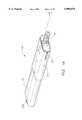
- FIGS. 1 and 1Aillustrate perspective views of the needleless injector of the present invention
- FIG. 2illustrates an exploded view of the needleless injector of the present invention
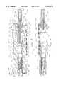
- FIG. 3is a cross-sectional view of the needleless injector of FIGS. 1 and 1A taken along the lines 3--3 in FIG. 1, showing the needleless injector with a vial of having a substantially full volume of liquid in position and with the power mechanism cocked for operation;
- FIG. 4is a cross-sectional view of the needleless injector of FIGS. 1 and 1A taken along the lines 4--4 in FIG. 1A, showing the needleless injector with a vial of liquid in position and with the power mechanism cocked for operation;
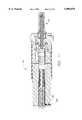
- FIG. 5is cross-sectional view of the needleless injector of FIG. 1, similar to the view of FIG. 3 but with the vial removed, which illustrates the action of cocking the power mechanism to prepare the injector to receive a vial having approximately half of the maximum volume of liquid medication;
- FIG. 6is a cross-sectional view of the needleless injector of FIG. 1, similar to the view of FIG. 3, showing the ejection of the liquid medication when the piston is moved by the springs;
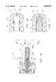
- FIG. 7is an enlarged cross-sectional view of the vial of FIG. 1 in position against the skin of a patient pictorially illustrating the flow of the liquid medicine into the tissues of the patient;
- FIG. 8is an enlarged cross-sectional view of the vial as in FIG. 6 showing the plugging effect of the end of the piston to preclude further use of the vial;
- FIG. 9is an enlarged cross-sectional view of the end of the vial in FIG. 8 showing the plugging effect in more detail;
- FIG. 10is a cross-sectional view of the needleless injector similar to FIG. 3, showing the dose adjustment stop moved to permit only a vial having a small dose of liquid medicine to be inserted into the needleless injector;
- FIG. 11is a cross-sectional view of the needleless injector of FIG. 10 with the vial of liquid medicine in position to be ejected;
- FIG. 12is a cross-sectional view of the needleless injector similar to FIG. 3, showing the dose adjustment stop moved and the injector cocked to permit a vial having a maximum dose of liquid medicine to be inserted into the needleless injector;
- FIG. 13is a cross-sectional view of the needleless injector of FIG. 12 with the vial of liquid medicine in position to be ejected;
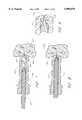
- FIG. 14is a cross-sectional view of an alternative embodiment of the needleless injector having a quarter-turn engagement mechanism between the vial and the power mechanism, and further having a modified orifice;
- FIG. 15Ais a front elevational view of the needleless injector of FIG. 14 showing the positioning of the vial onto the power mechanism prior to turning the vial to lock the vial to the power mechanism;
- FIG. 15Bis a front elevational view of the needleless injector of FIG. 14 showing the positioning of the vial after turning the vial to lock the vial to the power mechanism;
- FIG. 16is an enlarged cross-sectional view of a portion of the vial showing the modified orifice and the protuberance surrounding the inner portion of the orifice;
- FIG. 17further illustrates the enlarged cross-sectional view of FIG. 16 and shows the engagement of the funnel-shaped recess on the piston with the protuberance around the orifice to squeeze the orifice closed when the piston is driven forward.
- FIGS. 1 and 1Aillustrate perspective views of a preferred embodiment of a needleless injector 100 in accordance with the present invention.
- FIG. 1Ais substantially the same as FIG. 1 and is included to provide the section lines for FIG. 4.
- the needleless injector 100comprises a power mechanism 102 and a medication vial 104.
- the medication vial 104includes a threaded portion 106 which threadingly engages a threaded socket 108 of the power mechanism 102.
- the power mechanism 102further includes a bar-shaped main body portion 120 which has a generally oval-shaped cross-section.
- the main body portion 120is shown lying on its side in FIGS. 1 and 2 wherein an oval-shaped top end 122 has the socket 108 which receives the medication vial 104.
- the body portion 120has an oppositely disposed oval-shaped bottom end 124.
- the body portion 120has a first wide side 126 and an oppositely disposed second wide side 128.
- the body portion 120has a first narrow side 130 and an oppositely disposed second narrow side 132.
- a first trigger slot 150is formed in the first narrow side 130 to receive a first trigger 152.
- the first trigger 152is pivotably mounted proximate to its midpoint on a pin 154 which is pressed into a hole 156 through the first wide side 126, through a hole 157 in the trigger 152, and into a corresponding hole (not shown) in the second wide side 128.
- the first trigger 152has an activation portion 158 and a ratchet portion 160.
- a spring 162biases the first trigger 152 so that the activation portion 158 is forced out of the first narrow side 130 and so that the ratchet portion 160 is forced into the first narrow side 130.
- a second trigger slot 170is formed in the second narrow side 132 to receive a second trigger 172.
- the second trigger 172is pivotably mounted on a pin 174 which is pressed into a hole (not shown) through the second wide side 128, through a hole 177 in the trigger 172, and into a corresponding hole (not shown) in the second wide side 128.
- the second trigger 172has an activation portion 178 and a ratchet portion 180.
- a spring 182biases the second trigger 172 so that the activation portion 178 is forced out of the second narrow side 132 and so that the ratchet portion 180 is forced into the second narrow side 132.
- a slot 200is formed into the first wide side 126.
- the slot 200has a width on the first wide side 126 sufficient to receive a first sleeve spring 202.
- the width of the slot 200 at the first wide side 126extends for a depth slightly greater than the diameter of the first sleeve spring 202 so that the first sleeve spring 202 can be positioned in the slot 200 without an portion extending above the first wide side 126.
- the width of the slot 200narrows below the first sleeve spring 202 to a width less than the diameter of the first sleeve spring 202 so that first sleeve spring 202 is supported just below the first wide side 126.
- the narrow portion (not shown) of the first slot 200extends through the body portion 120 to the second wide side 128.
- a slot 204 substantially similar to the slot 200is formed into the second wide side 128 to receive a second sleeve spring 206.
- the wide portion of the second slot 204is not shown.
- the narrow portion of the second slot 204is shown extending through the first wide side 126.
- a cocking sleeve 220is positioned over the body portion 120.
- the cocking sleeve 220has a generally oval-shaped cross-section and is sized so that it fits over the body portion 120 and moves freely thereon from the top to the bottom without significant lateral play.
- the cocking sleevehas a top end 222, a bottom end 224, a first wide side 226, a second wide side 228, a first narrow side 230 and a second narrow side 232.
- the slots 240, 242have a sufficient width to encompass the activation portions 158 and 178 of the first trigger 152 and the second trigger 172, respectively.
- the cocking sleeve 220further includes a pair of holes 250 and 252 extending from the first wide surface 226 to the second wide surface 228. When the cocking sleeve is in position on the body portion 120, the holes 250 and 252 are aligned with the ends of the slots 200 and 204, respectively.
- a pair of pins 254 and 256are positioned in the holes 250 and 252, and extend thus through the slots 200 and 204.
- the pins 254 and 256engage respective first ends of the sleeve springs 202 and 206. The operation of the cocking sleeve 220 and the sleeve springs 202 and 206 will be discussed below.
- the body portion 120has a cylindrical bore 300 extending from the bottom end 124 to the top end 122.
- An upper portion 302 of the cylindrical bore 300 proximate to the top end 122has a largest diameter and is threaded to form the socket 108 which receives the medication vial 104.
- a lower portion 304 of the cylindrical bore 300 proximate to the bottom end 124a slightly smaller diameter.
- a lowermost portion of the lower portion 304is threaded to receive an adjustment plug described below.
- a second portion of the lower portion 304is not threaded.
- a middle portion 306 of the cylindrical bore 300 just below the upper portion 302i.e., to the left of the upper portion 302 in FIGS. 3 and 4) has a smaller diameter sized to receive a vial piston described below.
- a piston 310is positioned in the central bore 300.
- the piston 310has a first end 312 and a second end 314.
- the first end 312is positioned in the direction toward the bottom end 124 of the body portion 120, and the second end 314 is positioned in the direction of the top end 122.
- the piston 300has an outside diameter selected to be slightly smaller than the inside diameter of the cylindrical bore 300 so that the piston 310 moves freely within the cylindrical bore 300 without significant play.
- a first portion 316 of the piston 310 proximate to the first end 312is generally smooth.
- a second or ratchet portion 318 of the piston 310 proximate to the second end 318is milled or otherwise shaped to form a series of ratchets 320.
- the ratchet portion 318 shown in FIG. 3has ten ratchets 320 formed thereon.
- Each of the ratchets 320is tapered inward in the direction of the bottom end 124 of the body portion 120 to form a shoulder 322.
- the ratchet portions 160 and 180 of the first trigger 152 and of the second trigger 172are formed at an angle to generally match the taper of the ratchets 320 and to engage the shoulders 322.
- the operation of the ratchet portion 318 of the cylinder 310 with respect to the triggers 152 and 172will be explained below.
- a compression spring 330is positioned in the cylindrical bore 300 below the piston 310.
- a first end 332 of the compression spring 330rests against the first end 312 of the piston 310.
- a second end 334 of the compression spring 330is positioned in a direction toward the bottom end 124 of the body portion 120.
- a stroke adjustment plug 340is positioned in the cylindrical bore 300 below the compression spring 330.
- the stroke adjustment plug 340has a first portion 342 having a threaded outside diameter sized to fit within the cylindrical bore 300 and to engage the threaded portion of the cylindrical bore proximate to the bottom end 124 of the body portion 120.
- the stroke adjustment plug 340has a second extended portion 344 which extends from the first portion 342 in the direction toward the top end 122 of the body portion 120.
- the compression spring 330is positioned over the extended portion 344 such that the second end 334 of the compression spring 330 rests against a shoulder 346 of the first portion 342 of the stroke adjustment plug 340.
- the stroke adjustment plug 340has a central bore 348 formed therein.
- the central bore 348 of the stroke adjustment plug 340preferably has a square cross section or any other non-circular cross section for the reasons set forth below.
- a stroke adjustment knob 350is mounted in the cylindrical bore 300 proximate to the bottom end 124.
- a first portion 352 of the knob 350is a generally square bar portion which has a cross section sized to fit within the central bore 348 of the stroke adjustment plug 340.
- a second portion 354 of the knob 350is generally cylindrical and is sized to fit within the cylindrical bore 300 of the body portion 120.
- the second portion 354has a groove 356 formed therein. As shown in FIG.
- a set screw 360is positioned through a hole 362 in the first side 130 of the body portion 120 to engage the groove 356 in the second portion 354 of the knob 350.
- the set screw 360is initially threaded into the hole 362 sufficiently far to hold the knob 350 so that the second portion 354 cannot be removed from the cylindrical bore 300 but not so far as to press against the inside diameter of the groove 356.
- the knob 350can turn within the cylindrical bore 300.
- a third portion 358 of the knob 350is generally cylindrical and has a size greater than the size of the cylindrical bore 300.
- the third portion 358has a shoulder thereon which rests against the bottom end 124 of the body portion when the second portion 354 is inserted into the cylindrical bore 300.
- the outside diameter of the third portion 358is preferably knurled to provide a surface which can be readily gripped by a person's fingers so that the knob 350 can be turned.
- the stroke adjustment plug 340is turned by the interaction of the first portion 352 of the knob 350 and the central bore 348 of the stroke adjustment plug 340.
- the stroke adjustment plug 340will be threaded up or down the central bore 300.
- the stroke adjustment plug 340will slide on the first portion 352 of the knob 350 so that the knob 350 only needs to rotate and does not move up or down with respect to the central bore 300.
- the medicinal vial 104comprises a cylindrical portion 400 having an inside diameter.
- a first end 402 of the cylindrical portion 400is substantially closed with only a small opening 404 formed therein.
- a second end 406 of the cylindrical portion 400 proximate to the threaded portion 106is open for the full inside diameter.
- a piston 410is positioned within the cylindrical portion 400 through the second end 406.
- the piston 410has a main body portion 412 sized to fit within the cylindrical portion 400 and to move freely therein.
- a first end 414 of the piston 410extends from the cylindrical portion 400 for engagement with the piston 310, as described in more detail below.
- the piston 410comprises a solid plastic.
- the piston 410has a second end 418 which is positioned within the cylindrical portion 400.
- the second end 418has an outside diameter smaller than the inside diameter of the cylindrical portion 400.
- a rubber piston ring 420is positioned on the second end 418.
- the rubber piston ring 420is sized to fit tightly within the cylindrical portion 400 to form a seal therein while still permitting movement within the cylindrical portion 400.
- a liquid medicine 422is constrained between the first end 402 of the cylindrical portion 400 and the rubber piston ring 420.
- the opening 404 at the first end 402 of the cylindrical portion 400is tapered such that the outer portion of the opening 404 at the outside surface of the cylindrical portion 400 has a diameter selected to control the flow of medicinal liquid from the cylindrical portion 400.
- a diameter selected to control the flow of medicinal liquid from the cylindrical portion 400For example, an opening 404 having a diameter of approximately 0.006 inch has been advantageous in one embodiment.
- the opening 404is funnel shaped with its largest diameter inside the cylindrical portion 400 and its smaller diameter at the surface.
- the second end 418 of the piston 410has a central extended portion 430 which is aligned with the opening 404 in the cylindrical portion 400.
- the extended portion 430has an outside diameter that is smaller than the inside diameter of the opening 404 within the cylindrical portion 400. However, the outside diameter of the extended portion 430 is greater than the inside diameter of the opening 404 at the surface.
- the extended portion 430has a funnel-shaped recess 432 formed therein so that the extended portion 430 has relatively thin walls at the end proximate to the opening 404 and has thicker walls proximate to the piston ring 420.
- the vial 104When the present invention is assembled as illustrated in FIGS. 1, 3 and 4, it operates to provide a high pressure needleless injection system.
- the vial 104is first filled with an appropriate liquid medicine, such as, for example, insulin.
- the vial 104is provided as a sterile one-use-only vial.
- the vial 104is filled in a pharmaceutical environment by dispensing an appropriate amount of the liquid medicine in the vial 104 and then inserting the piston 410 into the cylindrical body portion 400 to seal the liquid therein.
- the first end 402is then sealed in an appropriate manner, and the filled vial 402 is packaged for distribution.
- the vial 104can be filled by a health care provider or, for self-injections of insulin and the like, by a patient.
- the vial 104is shipped in sterile packaging (not shown).
- the vial 104is removed from the sterile packaging and the first end 402 is inserted into a source of liquid medication. While holding the first end 402 of the vial 104 in the medication, the first end 414 of the piston 410 is pulled slowly to pull the piston 410 away from the first end 402 to thereby draw the liquid medicine into the vial 104 in a manner similar to filling a hypodermic syringe.
- the vial 104is preferably filled initially with more than the desired volume of medication, and the excess volume will be ejected, as discussed below, prior to injecting the medication into the patient.
- the vial 104is provided with conventional markings 500 (FIG. 1) to indicate the volume of liquid in the vial 104.
- the markingsmay be spaced to indicate 0.05 milliliter increments in volume.
- the vial 104has a total volume of 0.5 milliliters and thus has ten markings thereon.
- the vial 104can be distributed with a needle (not shown) attached to it so that it can be filled from sources of liquid medications which need to be punctured by a needle. See, for example, U.S. Pat. No. 4,680,027, which illustrates a removable needle. The needle is removed before engaging the vial 104 with the power mechanism 102.
- the power mechanism 102Before engaging the vial 104 with the power mechanism 102, the power mechanism 102 is cocked to provide the pressure and stroke required to eject the liquid medication from the vial 104 for a particular volume of liquid medication. As illustrated in FIG. 5, this is accomplished by moving the cocking sleeve downward (in the direction from the top end 122 to the bottom end 124).
- the pins 254 and 256are positioned proximate to the second end 314 of the piston 310 when the piston 310 is in its rest (uncocked) position.
- the sleeve 220When the cocking sleeve 220 is moved toward the bottom end 124 of the body portion 120, the sleeve 220 causes the pins 254 and 256 to slide in the slots 200 and 204 against the force of the sleeve springs 202 and 206. The pins 254 and 256 push the piston 310 downwardly in the bore 300 toward the bottom end 124 of the body portion 120 against the pressure of the compression spring 330. As the piston 310 moves toward the bottom end 124, the ratchet ends 160 and 180 of the triggers 152 and 172 are forced outwardly by the taper of each ratchet 320 and then snap inward behind each shoulder 322. Thus, the ratchet ends 160 and 180 engage each shoulder 322 and operate to hold the piston 310 in position against the pressure of the compression spring 330.
- the spacing between the shoulders 322 of the ratchets 320is selected to provide a predetermined incremental increase in the volume of the vial 104 accommodated by the power mechanism 102.
- each the distance between each shoulder 322corresponds to a 0.05 milliliter increase in the volume of the vial 104.
- the power mechanism 102includes an adjustment so that the user does not have to rely solely on counting the number of clicks. This feature is described below.
- the cocking sleeve 220is released and is returned to its original position, as shown in FIG. 1, by the pressure of the sleeve springs 202 and 206.
- the ratchet ends 160 and 180 of the triggers 152 and 172hold the piston 310 in its cocked position.
- the first end 414 of the piston 410contacts the second end 314 of the piston 310. If the vial 104 has been filled with more liquid than can be accommodated by the position of the piston 310, then, as the vial is screwed into the power mechanism 102, the first end 414 of the piston 410 will contact the second end 314 before the threaded portion 106 is fully seated in the socket 108. Thus, the piston 410 will move in the body portion 400 and force the excess liquid out of the vial 104.
- the ratchet portions 160 and 180are disengaged from the ratchets 320.
- the pressure of the compression spring 330operates against the first end 312 of the piston 310 to force the piston 310 toward the upper end 122 of the body portion 120.
- the second end 314 of the piston 310operates against the first end 414 of the piston 410 to force the piston 410 further into the body portion 400 of the vial 104 and thereby force the liquid medication 422 out of the vial 104 through the opening 404 as illustrated in FIG. 6.
- the power mechanism 102 of the present inventionrequires the user to press both activation portions 158 and 178 to release the piston 310. This safety feature reduces the likelihood that the power mechanism 102 will be accidentally triggered before the user has the vial 104 in place on the patient's skin and is ready to trigger the mechanism.
- the forward motion of the piston 310is stopped by metal outcroppings 510 which remain after forming the middle portion 306 of the central bore 300 and which extend above and below the middle portion 306 between the two slots 200 and 204. Because of the location of the section lines 4--4 in FIG. 1A, the outcroppings 510 are shown in phantom in FIG. 4. The outcroppings 510 prevent the second end 314 of the piston 310 from striking the pins 254 and 256 when the piston 310 reaches the end of its travel.
- the liquidis forced out of the opening 404 with sufficient force to penetrate the skin 600 of a patient and to penetrate the tissues 602 beneath the skin 600.
- FIG. 8 and FIG. 9when the liquid has been fully expelled from the vial 104 as the piston 410 travels to the end of the body portion 400, the extended portion 430 enters the funnel shaped inside portion of the opening 404.
- the relatively thin walls of the extended portion 430 caused by the funnel-shaped recess 432engage the inside walls of the hole 404 and force the hole 404 closed.
- the vial 104 and the piston 410are preferably formed from medical-grade plastic. The force of the engagement between the extended portion 430 and the inner wall of the hole 404 is sufficient to cause the two parts to mesh, thereby effectively preventing the vial 104 from being reused.
- the power mechanism 102be cocked so that the first end 414 of the piston 410 just engages the second end 314 of the piston 310 when the vial 104 is inserted into the power mechanism 102. If, the power mechanism is not cocked far enough, a portion of the liquid medication will be forced out of the vial 104 as the vial 104 is inserted into the socket 108, thus reducing the medication to less than the proper dosage. If, on the other hand, the power mechanism is cocked too far, the first end 414 of the piston 410 will not touch the second end 314 of the piston 310.
- the piston 310when the triggers 152 and 172 are activated, the piston 310 will travel a short distance and will be traveling a significant velocity before engaging the first end 414 of the piston 410. This can have the undesirable effect of causing the piston 310 to slap against the first end 414 of the piston 410 and may cause the user to fail to hold the end 402 of the vial 104 against the skin. Thus, the liquid medication 422 may tend to spray on the skin rather than to penetrate the skin as desired.
- the present inventionincludes a mechanism to reproducibly match the position of the cocked piston 310 to the first end 414 of the piston 410.
- the stroke adjustment plug 340permits the user to set the stroke of the piston 310 to the precise amount of the liquid medication to be dispensed so that when the vial 104 is engaged with the power mechanism 102, the first end 414 of the piston 410 will rest on the second end 314 of the piston 310.
- the piston 310will accelerate the piston 410 to smoothly force the liquid medication 422 out of the opening 404.
- the stroke adjustment plug 340is shown in a position so that the piston 310 can be moved by only the distance of two ratchets.
- the userplaces the stroke adjustment plug 340 in the position of FIG. 10 by turning the knurled knob 358 clockwise with respect to the bottom end 124 of the body portion 120.
- the stroke adjustment knob 350turns within the central bore 300 causing the first portion 352 (i.e., the square bar) to turn.
- the first portion 352is engaged with the central bore 348 of the stroke adjustment plug 340.
- the stroke adjustment plug 340turns within the central bore 300.
- the threaded engagement of the stroke adjustment plug 340 with the central bore 300causes the stroke adjustment plug 340 to advance toward the top end 122 of the body portion 120 to the position shown in FIG. 10.
- the usercan readily determine the correct position to place the stroke adjustment plug 340 by cocking the power mechanism 102 the required number of clicks (e.g., one click for 0.05 milliliters of medication, two clicks for 0.1 milliliter of medication, and so on).
- the stroke adjustment knob 350is turned until the user feels resistance when the stroke adjustment plug 340 engages the first end 312 of the piston 310.
- the stroke adjustment plug 340is then left in this position.
- the power mechanism 102is cocked by moving the cocking sheath 220 toward the bottom end 124, as shown, the piston 310 cannot be ratcheted beyond the position established by the stroke adjustment plug 340.
- the vial 104When the vial 104 is engaged with the power mechanism 102 when adjusted as in FIG. 10, the vial 104 can hold a maximum of 0.1 milliliters as illustrated in FIG. 11. Any excess medication will be ejected as the vial 104 is engaged, as discussed above.
- the stroke adjustment knob 350may be removed by retracting the screw 360, or, in the alternative, the screw 360 may be further engaged in the hole 362 until the end of the screw 360 frictionally engages the groove 356 so that the knob 350 cannot be turned.
- FIG. 12further illustrates the adjustment of the present invention, wherein the stroke adjustment plug 340 is positioned for maximum discharge of medication (e.g., 0.5 milliliter).
- FIG. 13illustrates the vial 104 in position in the power mechanism 102 when the power mechanism 102 has been cocked as illustrated in FIG. 12.
- the stroke adjustment plug 340has the further advantage that the force applied to the liquid medication for the initial injection of the medication through the skin is substantially the same regardless of the volume of the liquid to be ejected.
- the compression spring 330is compressed by substantially the same amount between the first end 312 of the piston 310 and the first portion 342 of the stroke adjustment plug 340.
- the force initially applied to the piston 310 and thus to the liquid medication 422is substantially the same for each volume.
- FIGS. 14-17illustrated an alternative embodiment of the needleless injector 700 in which a vial 702 can be more quickly engaged onto a power mechanism 704.
- the embodiment of FIGS. 14-17further includes a modified first end 710 of the vial 702 to assure that an orifice 712 is fully closed after the vial is emptied.
- the embodiment 700 of FIGS. 14-16is substantially similar to the previously described embodiment, and like elements are numbered the same.
- the vial 702engages the power mechanism 704 via a quarter-turn engagement mechanism comprising a first thread 720 and an oppositely disposed second thread 722 formed on a second end 724 of the vial 702.
- a quarter-turn engagement mechanismcomprising a first thread 720 and an oppositely disposed second thread 722 formed on a second end 724 of the vial 702.
- Each of the threads 720 and 722extends for approximately one-fourth of the circumference of the second end 724 of the vial 702.
- the threads 720 and 722have pitches selected to match corresponding threads 730 and 732 formed in a first end 734 of the power mechanism 704.
- the threads 730 and 732are conventional double lead threads which enable both threads 720 and 722 of the vial 702 to be engaged at the same time.
- the vial 702By turning the vial 702 one-quarter turn in the clockwise direction, as viewed in FIGS. 15A and 15B, the vial 702 is fully engaged with the power mechanism 704, thus enabling the user of the present invention to rapidly switch vials. This feature is particularly advantageous for mass inoculations of vaccine, and the like.
- the vial 702 in accordance with the embodiment of FIGS. 14-16has the modified orifice 712.
- the orifice 712extends into a cavity 740 of the vial 702.
- An inner wall 742 of the vial 702is formed into a conical protuberance 744 which surrounds the innermost portion of the orifice 712.
- the conical protuberance 744is sized to have a initial outside diameter greater than the inside diameter of the funnel-shaped recess 432 on the extended portion 430 of the piston 410.
- the inner wall 742 of the vial 702 proximate to the orifice 712is sloped generally toward the orifice 712, and the protuberance 744 extends from the sloped portion of the inner wall 742.
- the various portions of the power mechanism 102are fabricated from aluminum or other suitable metal, as indicated in cross-section herein.
- the power mechanism 102may be fabricated from high impact plastic to reduce the cost and the weight of the mechanism.
- the vial 104 and its component elementsare fabricated from a medical grade plastic such as is conventionally used in hypodermic syringes and the like.
Landscapes
- Health & Medical Sciences (AREA)
- Vascular Medicine (AREA)
- Engineering & Computer Science (AREA)
- Anesthesiology (AREA)
- Biomedical Technology (AREA)
- Heart & Thoracic Surgery (AREA)
- Hematology (AREA)
- Life Sciences & Earth Sciences (AREA)
- Animal Behavior & Ethology (AREA)
- General Health & Medical Sciences (AREA)
- Public Health (AREA)
- Veterinary Medicine (AREA)
- Infusion, Injection, And Reservoir Apparatuses (AREA)
Abstract
Description
Claims (5)
Priority Applications (3)
| Application Number | Priority Date | Filing Date | Title |
|---|---|---|---|
| US08/574,842US5899879A (en) | 1995-12-19 | 1995-12-19 | Spring-actuated needleless injector |
| TW086110658ATW346401B (en) | 1995-12-19 | 1997-07-26 | Spring-actuated needleless injector |
| US09/165,260US6083197A (en) | 1995-12-19 | 1998-10-01 | Spring-actuated needleless injector |
Applications Claiming Priority (1)
| Application Number | Priority Date | Filing Date | Title |
|---|---|---|---|
| US08/574,842US5899879A (en) | 1995-12-19 | 1995-12-19 | Spring-actuated needleless injector |
Publications (1)
| Publication Number | Publication Date |
|---|---|
| US5899879Atrue US5899879A (en) | 1999-05-04 |
Family
ID=24297881
Family Applications (2)
| Application Number | Title | Priority Date | Filing Date |
|---|---|---|---|
| US08/574,842Expired - Fee RelatedUS5899879A (en) | 1995-12-19 | 1995-12-19 | Spring-actuated needleless injector |
| US09/165,260Expired - Fee RelatedUS6083197A (en) | 1995-12-19 | 1998-10-01 | Spring-actuated needleless injector |
Family Applications After (1)
| Application Number | Title | Priority Date | Filing Date |
|---|---|---|---|
| US09/165,260Expired - Fee RelatedUS6083197A (en) | 1995-12-19 | 1998-10-01 | Spring-actuated needleless injector |
Country Status (2)
| Country | Link |
|---|---|
| US (2) | US5899879A (en) |
| TW (1) | TW346401B (en) |
Cited By (16)
| Publication number | Priority date | Publication date | Assignee | Title |
|---|---|---|---|---|
| USD422697S (en)* | 1999-01-13 | 2000-04-11 | Powderject Research Limited | Hand held injector |
| US20030042336A1 (en)* | 2001-09-04 | 2003-03-06 | Boehringer Ingelheim International Gmbh | Locking-stressing mechanism for a miniaturised high pressuriser |
| US6610042B2 (en)* | 1997-12-05 | 2003-08-26 | Felton Medical, Inc. | Disposable unit-dose jet-injection syringe for pre-filled and/or transfilled liquid injectable medical drug or vaccine products and method thereof |
| US20040015126A1 (en)* | 2000-03-03 | 2004-01-22 | Bernd Zierenberg | Needle-less injector of miniature type |
| EP1635896A1 (en)* | 2003-06-20 | 2006-03-22 | Allergan, Inc. | Needless injectors |
| US20070027428A1 (en)* | 2005-05-03 | 2007-02-01 | Pharmajet, Inc. | Vial system and method for needle-less injector |
| US20070055214A1 (en)* | 2005-08-10 | 2007-03-08 | Gilbert Scott J | Method for delivering drugs to tissue under microjet propulsion |
| US20070118094A1 (en)* | 2005-05-03 | 2007-05-24 | John Bingham | Needle-less injector and method of fluid delivery |
| US20070191762A1 (en)* | 2002-05-30 | 2007-08-16 | Kerry Quinn | Needleless injector and ampule system |
| US20080281261A1 (en)* | 2005-05-03 | 2008-11-13 | Genesis Medical Technologies, Inc. | Needle-less injector |
| WO2009098502A3 (en)* | 2008-02-08 | 2009-12-03 | Owen Mumford Limited | Autoinjector having a trigger and a cocking arrangement with an elongate flexible element |
| US9408972B2 (en) | 2011-08-02 | 2016-08-09 | Pharmajet, Inc. | Needle-free injection device |
| US9433735B2 (en) | 2011-12-13 | 2016-09-06 | Pharmajet Inc. | Needle-free intradermal injection device |
| US20220280389A1 (en)* | 2021-03-06 | 2022-09-08 | Control, Ltd. | Syringe Assembly & Method for Accurate Dosing |
| USD994110S1 (en)* | 2011-01-26 | 2023-08-01 | Kaleo, Inc. | Medicament delivery device cover |
| USD994111S1 (en)* | 2008-05-12 | 2023-08-01 | Kaleo, Inc. | Medicament delivery device cover |
Families Citing this family (91)
| Publication number | Priority date | Publication date | Assignee | Title |
|---|---|---|---|---|
| US6402718B1 (en) | 1992-08-17 | 2002-06-11 | Medrad, Inc. | Front-loading medical injector and syringe for use therewith |
| US5383858B1 (en) | 1992-08-17 | 1996-10-29 | Medrad Inc | Front-loading medical injector and syringe for use therewith |
| CZ297361B6 (en) | 1998-01-30 | 2006-11-15 | Novo Nordisk A/S | Injection syringe |
| US6488661B1 (en)* | 1998-07-31 | 2002-12-03 | Medrad, Inc. | Pressure control systems for medical injectors and syringes used therewith |
| DE19913344C1 (en)* | 1999-03-24 | 2000-08-24 | Deutscher Zahnarzt Verlag Dzv | Needleless injection syringe includes mounting for capsule of medicament with piston operated by spring, which can be tensioned from common rotary unit |
| US6802826B1 (en) | 1999-10-11 | 2004-10-12 | Felton International, Inc. | Universal anti-infectious protector for needleless injectors |
| US7074210B2 (en)* | 1999-10-11 | 2006-07-11 | Felton International, Inc. | Universal protector cap with auto-disable features for needle-free injectors |
| US6776776B2 (en)* | 1999-10-14 | 2004-08-17 | Becton, Dickinson And Company | Prefillable intradermal delivery device |
| US6494865B1 (en) | 1999-10-14 | 2002-12-17 | Becton Dickinson And Company | Intradermal delivery device including a needle assembly |
| US6569123B2 (en) | 1999-10-14 | 2003-05-27 | Becton, Dickinson And Company | Prefillable intradermal injector |
| US20020193740A1 (en) | 1999-10-14 | 2002-12-19 | Alchas Paul G. | Method of intradermally injecting substances |
| US6569143B2 (en) | 1999-10-14 | 2003-05-27 | Becton, Dickinson And Company | Method of intradermally injecting substances |
| US6843781B2 (en)* | 1999-10-14 | 2005-01-18 | Becton, Dickinson And Company | Intradermal needle |
| US6382204B1 (en)* | 1999-10-14 | 2002-05-07 | Becton Dickinson And Company | Drug delivery system including holder and drug container |
| US7887506B1 (en) | 1999-11-23 | 2011-02-15 | Pulse Needlefree Systems, Inc. | Safety mechanism to prevent accidental patient injection and methods of same |
| US6770054B1 (en) | 1999-11-23 | 2004-08-03 | Felton International, Inc. | Injector assembly with driving means and locking means |
| US7029457B2 (en)* | 1999-11-23 | 2006-04-18 | Felton International, Inc. | Jet injector with hand piece |
| US6958053B1 (en)* | 1999-11-24 | 2005-10-25 | Medrad, Inc. | Injector providing drive member advancement and engagement with syringe plunger, and method of connecting a syringe to an injector |
| US6652489B2 (en)* | 2000-02-07 | 2003-11-25 | Medrad, Inc. | Front-loading medical injector and syringes, syringe interfaces, syringe adapters and syringe plungers for use therewith |
| US6716190B1 (en)* | 2000-04-19 | 2004-04-06 | Scimed Life Systems, Inc. | Device and methods for the delivery and injection of therapeutic and diagnostic agents to a target site within a body |
| US6663602B2 (en) | 2000-06-16 | 2003-12-16 | Novo Nordisk A/S | Injection device |
| AUPQ867900A0 (en) | 2000-07-10 | 2000-08-03 | Medrad, Inc. | Medical injector system |
| JP2002263106A (en)* | 2001-03-12 | 2002-09-17 | Olympus Optical Co Ltd | Optical probe device |
| CA2451816A1 (en)* | 2001-06-29 | 2003-01-09 | Becton, Dickinson And Company | Intradermal delivery of vaccines and gene therapeutic agents via microcannula |
| US20060018877A1 (en)* | 2001-06-29 | 2006-01-26 | Mikszta John A | Intradermal delivery of vacccines and therapeutic agents |
| US7553294B2 (en) | 2002-05-30 | 2009-06-30 | Medrad, Inc. | Syringe plunger sensing mechanism for a medical injector |
| GB0304823D0 (en) | 2003-03-03 | 2003-04-09 | Dca Internat Ltd | Improvements in and relating to a pen-type injector |
| GB0304822D0 (en) | 2003-03-03 | 2003-04-09 | Dca Internat Ltd | Improvements in and relating to a pen-type injector |
| EP2210634A1 (en)* | 2009-01-22 | 2010-07-28 | Sanofi-Aventis Deutschland GmbH | Drug delivery device dose setting mechanism |
| GB0308267D0 (en)* | 2003-04-10 | 2003-05-14 | Dca Design Int Ltd | Improvements in and relating to a pen-type injector |
| US7419478B1 (en) | 2003-06-25 | 2008-09-02 | Medrad, Inc. | Front-loading syringe for medical injector having a flexible syringe retaining ring |
| USD1031029S1 (en) | 2003-11-25 | 2024-06-11 | Bayer Healthcare Llc | Syringe plunger |
| US7666169B2 (en) | 2003-11-25 | 2010-02-23 | Medrad, Inc. | Syringe and syringe plungers for use with medical injectors |
| US20050249699A1 (en)* | 2004-05-05 | 2005-11-10 | Stoff Jesse A | Immunodynamic complexes and methods for using and preparing such complexes |
| GB2414404B (en) | 2004-05-28 | 2009-06-03 | Cilag Ag Int | Injection device |
| GB2414401B (en) | 2004-05-28 | 2009-06-17 | Cilag Ag Int | Injection device |
| GB2414409B (en) | 2004-05-28 | 2009-11-18 | Cilag Ag Int | Injection device |
| GB2414400B (en) | 2004-05-28 | 2009-01-14 | Cilag Ag Int | Injection device |
| GB2414399B (en) | 2004-05-28 | 2008-12-31 | Cilag Ag Int | Injection device |
| GB2414403B (en)* | 2004-05-28 | 2009-01-07 | Cilag Ag Int | Injection device |
| GB2414406B (en) | 2004-05-28 | 2009-03-18 | Cilag Ag Int | Injection device |
| GB2414405B (en)* | 2004-05-28 | 2009-01-14 | Cilag Ag Int | Injection device |
| GB2414775B (en) | 2004-05-28 | 2008-05-21 | Cilag Ag Int | Releasable coupling and injection device |
| GB2414402B (en) | 2004-05-28 | 2009-04-22 | Cilag Ag Int | Injection device |
| EP1781180A2 (en)* | 2004-07-08 | 2007-05-09 | CliniWave, Inc. | Rolling tube apparatus and method for treating a wound |
| ATE444090T1 (en) | 2004-10-21 | 2009-10-15 | Novo Nordisk As | SELECTION MECHANISM FOR A ROTARY PIN |
| GB2424836B (en) | 2005-04-06 | 2010-09-22 | Cilag Ag Int | Injection device (bayonet cap removal) |
| GB2424838B (en) | 2005-04-06 | 2011-02-23 | Cilag Ag Int | Injection device (adaptable drive) |
| GB2427826B (en) | 2005-04-06 | 2010-08-25 | Cilag Ag Int | Injection device comprising a locking mechanism associated with integrally formed biasing means |
| GB2424835B (en) | 2005-04-06 | 2010-06-09 | Cilag Ag Int | Injection device (modified trigger) |
| GB2425062B (en) | 2005-04-06 | 2010-07-21 | Cilag Ag Int | Injection device |
| US20090043264A1 (en) | 2005-04-24 | 2009-02-12 | Novo Nordisk A/S | Injection Device |
| PL1759729T3 (en) | 2005-08-30 | 2010-09-30 | Cilag Gmbh Int | Needle assembly for a prefilled syringe system |
| US20110098656A1 (en) | 2005-09-27 | 2011-04-28 | Burnell Rosie L | Auto-injection device with needle protecting cap having outer and inner sleeves |
| CN101400394B (en) | 2006-03-10 | 2012-07-04 | 诺沃-诺迪斯克有限公司 | An injection device having a gearing arrangement |
| JP5062768B2 (en) | 2006-03-10 | 2012-10-31 | ノボ・ノルデイスク・エー/エス | INJECTION DEVICE AND METHOD FOR REPLACING CARTRIDGE OF THE DEVICE |
| US8926569B2 (en) | 2006-03-15 | 2015-01-06 | Bayer Medical Care Inc. | Plunger covers and plungers for use in syringes and methods of fabricating plunger covers and plungers for use in syringes |
| ATE458517T1 (en) | 2006-05-16 | 2010-03-15 | Novo Nordisk As | TRANSMISSION MECHANISM FOR AN INJECTION DEVICE |
| JP5253387B2 (en) | 2006-05-18 | 2013-07-31 | ノボ・ノルデイスク・エー/エス | Injection device with mode locking means |
| GB2438593B (en) | 2006-06-01 | 2011-03-30 | Cilag Gmbh Int | Injection device (cap removal feature) |
| GB2438590B (en) | 2006-06-01 | 2011-02-09 | Cilag Gmbh Int | Injection device |
| GB2438591B (en) | 2006-06-01 | 2011-07-13 | Cilag Gmbh Int | Injection device |
| EP2109474B2 (en) | 2007-02-05 | 2019-01-30 | Novo Nordisk A/S | Injection button |
| USD942005S1 (en) | 2007-03-14 | 2022-01-25 | Bayer Healthcare Llc | Orange syringe plunger cover |
| USD1002840S1 (en) | 2007-03-14 | 2023-10-24 | Bayer Healthcare Llc | Syringe plunger |
| USD847985S1 (en) | 2007-03-14 | 2019-05-07 | Bayer Healthcare Llc | Syringe plunger cover |
| BRPI0809265A2 (en) | 2007-03-23 | 2014-10-07 | Novo Nordisk As | INJECTION DEVICE INCLUDING A TIGHTENING NUT |
| GB2461086B (en) | 2008-06-19 | 2012-12-05 | Cilag Gmbh Int | Injection device |
| GB2461087B (en) | 2008-06-19 | 2012-09-26 | Cilag Gmbh Int | Injection device |
| GB2461089B (en) | 2008-06-19 | 2012-09-19 | Cilag Gmbh Int | Injection device |
| GB2461085B (en) | 2008-06-19 | 2012-08-29 | Cilag Gmbh Int | Injection device |
| GB2461084B (en) | 2008-06-19 | 2012-09-26 | Cilag Gmbh Int | Fluid transfer assembly |
| CN102939120B (en) | 2010-06-04 | 2016-12-07 | 拜耳医药保健有限责任公司 | Systems and methods for planning and monitoring the use of multiple doses of radiopharmaceuticals on radiopharmaceutical syringes |
| JP6069351B2 (en) | 2011-12-29 | 2017-02-01 | ノボ・ノルデイスク・エー/エス | Torsion spring type automatic syringe with dial-up / dial-down administration mechanism |
| US9174003B2 (en) | 2012-09-28 | 2015-11-03 | Bayer Medical Care Inc. | Quick release plunger |
| US9808579B2 (en) | 2013-05-08 | 2017-11-07 | Elwha Llc | Needleless injector systems, and related methods and components |
| GB2515038A (en) | 2013-06-11 | 2014-12-17 | Cilag Gmbh Int | Injection device |
| GB2515032A (en) | 2013-06-11 | 2014-12-17 | Cilag Gmbh Int | Guide for an injection device |
| GB2517896B (en) | 2013-06-11 | 2015-07-08 | Cilag Gmbh Int | Injection device |
| GB2515039B (en) | 2013-06-11 | 2015-05-27 | Cilag Gmbh Int | Injection Device |
| AU2015231396B2 (en) | 2014-03-19 | 2018-12-06 | Bayer Healthcare Llc | System for syringe engagement to an injector |
| US9480797B1 (en) | 2015-10-28 | 2016-11-01 | Bayer Healthcare Llc | System and method for syringe plunger engagement with an injector |
| PL227678B1 (en) | 2015-12-22 | 2018-01-31 | Copernicus Spolka Z Ograniczona Odpowiedzialnoscia | Control and drive system for the device intended for injection and the device for making injections equipped with such a system |
| PL3108914T3 (en) | 2016-07-07 | 2019-08-30 | Copernicus Sp. Z O.O. | Injection device for delivering a defined number of equal doses of a liquid substance |
| US10589029B2 (en)* | 2016-12-29 | 2020-03-17 | ChitoTech (Keifiat Tolid Takapoo) | Adjustable needle-free injector |
| HUE063479T2 (en) | 2017-01-06 | 2024-01-28 | Bayer Healthcare Llc | Syringe plunger with dynamic seal |
| PL232651B1 (en) | 2017-07-18 | 2019-07-31 | Copernicus Spolka Z Ograniczona Odpowiedzialnoscia | Coupling with locking system for the medical injecting device |
| RS65380B1 (en) | 2017-08-24 | 2024-04-30 | Novo Nordisk As | Glp-1 compositions and uses thereof |
| HUE061426T2 (en) | 2018-02-27 | 2023-06-28 | Bayer Healthcare Llc | Syringe piston switch mechanism |
| IL294520A (en) | 2020-02-18 | 2022-09-01 | Novo Nordisk As | Pharmaceutical formulations |
| BR112022023788A2 (en) | 2020-06-18 | 2022-12-27 | Bayer Healthcare Llc | SYSTEM AND METHOD OF COUPLING A SYRINGE PLUNGER WITH AN INJECTOR |
Citations (62)
| Publication number | Priority date | Publication date | Assignee | Title |
|---|---|---|---|---|
| US24419A (en)* | 1859-06-14 | Improvement in seeding-machines | ||
| US569887A (en)* | 1896-10-20 | Scraper | ||
| US2547099A (en)* | 1948-03-11 | 1951-04-03 | Becton Dickinson Co | Injection device and ampoule |
| US2605763A (en)* | 1948-01-31 | 1952-08-05 | Becton Dickinson Co | Injection device |
| US2635601A (en)* | 1951-11-15 | 1953-04-21 | Becton Dickinson Co | Injection device |
| US2645223A (en)* | 1951-02-17 | 1953-07-14 | Becton Dickinson Co | Injection device |
| US2699166A (en)* | 1949-07-29 | 1955-01-11 | Becton Dickinson Co | Hypodermic injection unit |
| US2737946A (en)* | 1949-09-01 | 1956-03-13 | Jr George N Hein | Hypodermic injection apparatus |
| US2764977A (en)* | 1951-05-24 | 1956-10-02 | Becton Dickinson Co | Hypodermic injection mechanism |
| US2800903A (en)* | 1947-07-30 | 1957-07-30 | Becton Dickinson Co | Injection apparatus |
| USRE24419E (en) | 1958-01-21 | Ziherl et au | ||
| US2821193A (en)* | 1952-07-22 | 1958-01-28 | Geoffrey W Walker | Multiple injection inoculator instrument |
| US2821981A (en)* | 1954-07-21 | 1958-02-04 | Geoffrey W Walker | Multi-shot inoculant injector instrument with adjustable ejection pressure control |
| US3057349A (en)* | 1959-12-14 | 1962-10-09 | Ismach Aaron | Multi-dose jet injection device |
| US3115133A (en)* | 1962-05-15 | 1963-12-24 | Morando Emilio Donald | Needleless prefilled disposable hypodermic injector |
| US3138157A (en)* | 1961-05-12 | 1964-06-23 | Z & W Mfg Corp | Inoculant injector instrument |
| US3202151A (en)* | 1963-04-08 | 1965-08-24 | Scherer Corp R P | Multidose jet injector |
| US3292622A (en)* | 1964-09-21 | 1966-12-20 | Oscar H Banker | Power operated inoculator |
| US3292621A (en)* | 1963-07-19 | 1966-12-20 | Oscar H Banker | Jet type protable inoculator |
| US3461867A (en)* | 1966-03-14 | 1969-08-19 | Mizzy Inc | Needleless injector |
| US3688765A (en)* | 1969-10-03 | 1972-09-05 | Jack S Gasaway | Hypodermic injection device |
| US3695266A (en)* | 1970-06-18 | 1972-10-03 | Maurice G Lussier | Needleless sequential dosing syringe |
| US3714943A (en)* | 1970-12-01 | 1973-02-06 | H Yanof | Medicament injectors |
| US3763359A (en)* | 1972-05-15 | 1973-10-02 | Bell Telephone Labor Inc | Apparatus for equalizing a transmission system |
| US3788315A (en)* | 1971-04-20 | 1974-01-29 | S Laurens | Disposable cutaneous transjector |
| US3805783A (en)* | 1971-02-12 | 1974-04-23 | A Ismach | Hand powered hypodermic jet injector gun |
| US3815594A (en)* | 1972-08-10 | 1974-06-11 | N Doherty | Needleless inoculator |
| US3853125A (en)* | 1971-10-05 | 1974-12-10 | W Clark | Disposable needleless injector |
| US3859996A (en)* | 1973-07-18 | 1975-01-14 | Mizzy Inc | Multi-dose injector |
| US3908651A (en)* | 1974-05-17 | 1975-09-30 | Daystrol Scient Inc | Medicament injection device |
| US3933155A (en)* | 1975-01-23 | 1976-01-20 | Mizzy Inc. | Pressure injector apparatus having improved trigger mechanism |
| US3945383A (en)* | 1974-08-08 | 1976-03-23 | Smithkline Corporation | Unit dose ampul for jet injector |
| US3945379A (en)* | 1974-08-08 | 1976-03-23 | Smithkline Corporation | Injection device |
| US4004575A (en)* | 1974-04-02 | 1977-01-25 | Walter Sarstedt Kunststoff-Spritzgusswerk | Apparatus for loading blood extracting devices |
| US4031889A (en)* | 1975-03-25 | 1977-06-28 | William Floyd Pike | Power operated aspirating hypodermic syringe |
| US4059107A (en)* | 1975-05-08 | 1977-11-22 | Asahi Kasei Kogyo Kabushiki Kaisha | Two step type pressurized injector |
| US4089334A (en)* | 1976-10-07 | 1978-05-16 | Schwebel Paul R | Pyrotechnically powered needleless injector |
| US4103684A (en)* | 1976-12-30 | 1978-08-01 | Aaron Ismach | Hydraulically powered hypodermic injector with adapters for reducing and increasing fluid injection force |
| US4124024A (en)* | 1977-03-03 | 1978-11-07 | Schwebel Paul R | Disposable hypodermic injection ampule |
| US4128098A (en)* | 1976-12-06 | 1978-12-05 | American Hospital Supply Corporation | Valved spike transfer device |
| US4301795A (en)* | 1978-07-22 | 1981-11-24 | Hoechst Aktiengesellschaft | Vaccination gun |
| US4329988A (en)* | 1980-12-23 | 1982-05-18 | Survival Technology, Inc. | Plural injection assembly |
| US4342310A (en)* | 1980-07-08 | 1982-08-03 | Istvan Lindmayer | Hydro-pneumatic jet injector |
| US4400172A (en)* | 1981-04-16 | 1983-08-23 | Hoechst Aktiengesellschaft | Needle-less injection instrument |
| US4403989A (en)* | 1981-09-14 | 1983-09-13 | Syntex (U.S.A.) Inc. | Injection device |
| US4403609A (en)* | 1981-02-24 | 1983-09-13 | Cohen Edgar C | Vacuum-compression injector |
| US4421508A (en)* | 1981-02-24 | 1983-12-20 | Cohen Edgar C | Vacuum-compression injector |
| US4447225A (en)* | 1982-03-22 | 1984-05-08 | Taff Barry E | Multidose jet injector |
| US4475905A (en)* | 1982-09-30 | 1984-10-09 | Himmelstrup Anders B | Injection device |
| US4507113A (en)* | 1982-11-22 | 1985-03-26 | Derata Corporation | Hypodermic jet injector |
| US4518385A (en)* | 1983-06-13 | 1985-05-21 | Preci-Tech Ltd. | Disposable syringe for needleless injector |
| US4592742A (en)* | 1984-08-28 | 1986-06-03 | Sergio Landau | Pressure hypodermic syringe |
| US4596556A (en)* | 1985-03-25 | 1986-06-24 | Bioject, Inc. | Hypodermic injection apparatus |
| US5106371A (en)* | 1990-02-28 | 1992-04-21 | Mo Zhao | Clinical Syringe to be rendered useless after being used once |
| US5211628A (en)* | 1991-09-30 | 1993-05-18 | Marshall John M | Syringe with automatic retracting needle |
| US5312348A (en)* | 1993-07-30 | 1994-05-17 | Sans Ten S | Single-usage disposable hypodermic syringe |
| US5527284A (en)* | 1994-05-18 | 1996-06-18 | Randall E. Ohnemus | Single use syringes |
| US5531705A (en)* | 1990-11-30 | 1996-07-02 | Nujenko Pty Ltd | Syringe unit |
| US5556384A (en)* | 1991-07-18 | 1996-09-17 | Da Encarnac+E,Otl A+Ee O; Fernando A. F. | Self-destructive hypodermic syringe |
| US5569203A (en)* | 1995-06-23 | 1996-10-29 | Chen; Long-Hsiung | Simplified safety syringe with retractable self-biased needle and minimized plunger |
| US5575774A (en)* | 1995-10-24 | 1996-11-19 | Chen; Long-Hsiung | Structure of safety hypodermic syringe |
| US5578015A (en)* | 1989-09-18 | 1996-11-26 | Robb Pascal Patent Limited | Safety syringe incorporating automatic needle holder release |
Family Cites Families (5)
| Publication number | Priority date | Publication date | Assignee | Title |
|---|---|---|---|---|
| CA569887A (en)* | 1959-02-03 | P. Scherer Robert | Hypo jet injector | |
| US3763859A (en)* | 1971-11-11 | 1973-10-09 | Pigmy Health Prod Inc | Injector apparatus |
| US4680027A (en)* | 1985-12-12 | 1987-07-14 | Injet Medical Products, Inc. | Needleless hypodermic injection device |
| US5599302A (en)* | 1995-01-09 | 1997-02-04 | Medi-Ject Corporation | Medical injection system and method, gas spring thereof and launching device using gas spring |
| US5865795A (en)* | 1996-02-29 | 1999-02-02 | Medi-Ject Corporation | Safety mechanism for injection devices |
- 1995
- 1995-12-19USUS08/574,842patent/US5899879A/ennot_activeExpired - Fee Related
- 1997
- 1997-07-26TWTW086110658Apatent/TW346401B/enactive
- 1998
- 1998-10-01USUS09/165,260patent/US6083197A/ennot_activeExpired - Fee Related
Patent Citations (62)
| Publication number | Priority date | Publication date | Assignee | Title |
|---|---|---|---|---|
| US569887A (en)* | 1896-10-20 | Scraper | ||
| US24419A (en)* | 1859-06-14 | Improvement in seeding-machines | ||
| USRE24419E (en) | 1958-01-21 | Ziherl et au | ||
| US2800903A (en)* | 1947-07-30 | 1957-07-30 | Becton Dickinson Co | Injection apparatus |
| US2605763A (en)* | 1948-01-31 | 1952-08-05 | Becton Dickinson Co | Injection device |
| US2547099A (en)* | 1948-03-11 | 1951-04-03 | Becton Dickinson Co | Injection device and ampoule |
| US2699166A (en)* | 1949-07-29 | 1955-01-11 | Becton Dickinson Co | Hypodermic injection unit |
| US2737946A (en)* | 1949-09-01 | 1956-03-13 | Jr George N Hein | Hypodermic injection apparatus |
| US2645223A (en)* | 1951-02-17 | 1953-07-14 | Becton Dickinson Co | Injection device |
| US2764977A (en)* | 1951-05-24 | 1956-10-02 | Becton Dickinson Co | Hypodermic injection mechanism |
| US2635601A (en)* | 1951-11-15 | 1953-04-21 | Becton Dickinson Co | Injection device |
| US2821193A (en)* | 1952-07-22 | 1958-01-28 | Geoffrey W Walker | Multiple injection inoculator instrument |
| US2821981A (en)* | 1954-07-21 | 1958-02-04 | Geoffrey W Walker | Multi-shot inoculant injector instrument with adjustable ejection pressure control |
| US3057349A (en)* | 1959-12-14 | 1962-10-09 | Ismach Aaron | Multi-dose jet injection device |
| US3138157A (en)* | 1961-05-12 | 1964-06-23 | Z & W Mfg Corp | Inoculant injector instrument |
| US3115133A (en)* | 1962-05-15 | 1963-12-24 | Morando Emilio Donald | Needleless prefilled disposable hypodermic injector |
| US3202151A (en)* | 1963-04-08 | 1965-08-24 | Scherer Corp R P | Multidose jet injector |
| US3292621A (en)* | 1963-07-19 | 1966-12-20 | Oscar H Banker | Jet type protable inoculator |
| US3292622A (en)* | 1964-09-21 | 1966-12-20 | Oscar H Banker | Power operated inoculator |
| US3461867A (en)* | 1966-03-14 | 1969-08-19 | Mizzy Inc | Needleless injector |
| US3688765A (en)* | 1969-10-03 | 1972-09-05 | Jack S Gasaway | Hypodermic injection device |
| US3695266A (en)* | 1970-06-18 | 1972-10-03 | Maurice G Lussier | Needleless sequential dosing syringe |
| US3714943A (en)* | 1970-12-01 | 1973-02-06 | H Yanof | Medicament injectors |
| US3805783A (en)* | 1971-02-12 | 1974-04-23 | A Ismach | Hand powered hypodermic jet injector gun |
| US3788315A (en)* | 1971-04-20 | 1974-01-29 | S Laurens | Disposable cutaneous transjector |
| US3853125A (en)* | 1971-10-05 | 1974-12-10 | W Clark | Disposable needleless injector |
| US3763359A (en)* | 1972-05-15 | 1973-10-02 | Bell Telephone Labor Inc | Apparatus for equalizing a transmission system |
| US3815594A (en)* | 1972-08-10 | 1974-06-11 | N Doherty | Needleless inoculator |
| US3859996A (en)* | 1973-07-18 | 1975-01-14 | Mizzy Inc | Multi-dose injector |
| US4004575A (en)* | 1974-04-02 | 1977-01-25 | Walter Sarstedt Kunststoff-Spritzgusswerk | Apparatus for loading blood extracting devices |
| US3908651A (en)* | 1974-05-17 | 1975-09-30 | Daystrol Scient Inc | Medicament injection device |
| US3945383A (en)* | 1974-08-08 | 1976-03-23 | Smithkline Corporation | Unit dose ampul for jet injector |
| US3945379A (en)* | 1974-08-08 | 1976-03-23 | Smithkline Corporation | Injection device |
| US3933155A (en)* | 1975-01-23 | 1976-01-20 | Mizzy Inc. | Pressure injector apparatus having improved trigger mechanism |
| US4031889A (en)* | 1975-03-25 | 1977-06-28 | William Floyd Pike | Power operated aspirating hypodermic syringe |
| US4059107A (en)* | 1975-05-08 | 1977-11-22 | Asahi Kasei Kogyo Kabushiki Kaisha | Two step type pressurized injector |
| US4089334A (en)* | 1976-10-07 | 1978-05-16 | Schwebel Paul R | Pyrotechnically powered needleless injector |
| US4128098A (en)* | 1976-12-06 | 1978-12-05 | American Hospital Supply Corporation | Valved spike transfer device |
| US4103684A (en)* | 1976-12-30 | 1978-08-01 | Aaron Ismach | Hydraulically powered hypodermic injector with adapters for reducing and increasing fluid injection force |
| US4124024A (en)* | 1977-03-03 | 1978-11-07 | Schwebel Paul R | Disposable hypodermic injection ampule |
| US4301795A (en)* | 1978-07-22 | 1981-11-24 | Hoechst Aktiengesellschaft | Vaccination gun |
| US4342310A (en)* | 1980-07-08 | 1982-08-03 | Istvan Lindmayer | Hydro-pneumatic jet injector |
| US4329988A (en)* | 1980-12-23 | 1982-05-18 | Survival Technology, Inc. | Plural injection assembly |
| US4421508A (en)* | 1981-02-24 | 1983-12-20 | Cohen Edgar C | Vacuum-compression injector |
| US4403609A (en)* | 1981-02-24 | 1983-09-13 | Cohen Edgar C | Vacuum-compression injector |
| US4400172A (en)* | 1981-04-16 | 1983-08-23 | Hoechst Aktiengesellschaft | Needle-less injection instrument |
| US4403989A (en)* | 1981-09-14 | 1983-09-13 | Syntex (U.S.A.) Inc. | Injection device |
| US4447225A (en)* | 1982-03-22 | 1984-05-08 | Taff Barry E | Multidose jet injector |
| US4475905A (en)* | 1982-09-30 | 1984-10-09 | Himmelstrup Anders B | Injection device |
| US4507113A (en)* | 1982-11-22 | 1985-03-26 | Derata Corporation | Hypodermic jet injector |
| US4518385A (en)* | 1983-06-13 | 1985-05-21 | Preci-Tech Ltd. | Disposable syringe for needleless injector |
| US4592742A (en)* | 1984-08-28 | 1986-06-03 | Sergio Landau | Pressure hypodermic syringe |
| US4596556A (en)* | 1985-03-25 | 1986-06-24 | Bioject, Inc. | Hypodermic injection apparatus |
| US5578015A (en)* | 1989-09-18 | 1996-11-26 | Robb Pascal Patent Limited | Safety syringe incorporating automatic needle holder release |
| US5106371A (en)* | 1990-02-28 | 1992-04-21 | Mo Zhao | Clinical Syringe to be rendered useless after being used once |
| US5531705A (en)* | 1990-11-30 | 1996-07-02 | Nujenko Pty Ltd | Syringe unit |
| US5556384A (en)* | 1991-07-18 | 1996-09-17 | Da Encarnac+E,Otl A+Ee O; Fernando A. F. | Self-destructive hypodermic syringe |
| US5211628A (en)* | 1991-09-30 | 1993-05-18 | Marshall John M | Syringe with automatic retracting needle |
| US5312348A (en)* | 1993-07-30 | 1994-05-17 | Sans Ten S | Single-usage disposable hypodermic syringe |
| US5527284A (en)* | 1994-05-18 | 1996-06-18 | Randall E. Ohnemus | Single use syringes |
| US5569203A (en)* | 1995-06-23 | 1996-10-29 | Chen; Long-Hsiung | Simplified safety syringe with retractable self-biased needle and minimized plunger |
| US5575774A (en)* | 1995-10-24 | 1996-11-19 | Chen; Long-Hsiung | Structure of safety hypodermic syringe |
Cited By (42)
| Publication number | Priority date | Publication date | Assignee | Title |
|---|---|---|---|---|
| US6610042B2 (en)* | 1997-12-05 | 2003-08-26 | Felton Medical, Inc. | Disposable unit-dose jet-injection syringe for pre-filled and/or transfilled liquid injectable medical drug or vaccine products and method thereof |
| USD422697S (en)* | 1999-01-13 | 2000-04-11 | Powderject Research Limited | Hand held injector |
| US20040015126A1 (en)* | 2000-03-03 | 2004-01-22 | Bernd Zierenberg | Needle-less injector of miniature type |
| US6689092B2 (en)* | 2000-03-03 | 2004-02-10 | Boehringer International Gmbh | Needle-less injector of miniature type |
| US6932789B2 (en) | 2000-03-03 | 2005-08-23 | Boehringer Ingelheim International Gmbh | Needle-less injector of miniature type |
| US20030042336A1 (en)* | 2001-09-04 | 2003-03-06 | Boehringer Ingelheim International Gmbh | Locking-stressing mechanism for a miniaturised high pressuriser |
| US6945472B2 (en)* | 2001-09-04 | 2005-09-20 | Boehringer Ingelheim International Gmbh | Locking-stressing mechanism for a miniaturised high pressuriser |
| US20050269424A1 (en)* | 2001-09-04 | 2005-12-08 | Boehringer Ingelheim International Gmbh | Locking-tensioning mechanism for a miniaturised high pressuriser |
| US7726588B2 (en)* | 2001-09-04 | 2010-06-01 | Boehringer Ingelheim International Gmbh | Locking-tensioning mechanism for a miniaturised high pressuriser |
| US20070191762A1 (en)* | 2002-05-30 | 2007-08-16 | Kerry Quinn | Needleless injector and ampule system |
| US20070043319A1 (en)* | 2003-06-20 | 2007-02-22 | Kimmel Steven D | Needlless injectors |
| EP1635896A1 (en)* | 2003-06-20 | 2006-03-22 | Allergan, Inc. | Needless injectors |
| US20070118094A1 (en)* | 2005-05-03 | 2007-05-24 | John Bingham | Needle-less injector and method of fluid delivery |
| US7699802B2 (en) | 2005-05-03 | 2010-04-20 | Pharmajet, Inc. | Needle-less injector |
| US9333300B2 (en) | 2005-05-03 | 2016-05-10 | Pharmajet, Inc. | Needle-less injector and method of fluid delivery |
| US20070027428A1 (en)* | 2005-05-03 | 2007-02-01 | Pharmajet, Inc. | Vial system and method for needle-less injector |
| US20080281261A1 (en)* | 2005-05-03 | 2008-11-13 | Genesis Medical Technologies, Inc. | Needle-less injector |
| US7618393B2 (en) | 2005-05-03 | 2009-11-17 | Pharmajet, Inc. | Needle-less injector and method of fluid delivery |
| US10099011B2 (en) | 2005-05-03 | 2018-10-16 | Pharmajet, Inc. | Needle-less injector and method of fluid delivery |
| US8529500B2 (en) | 2005-05-03 | 2013-09-10 | Pharmajet, Inc. | Needle-less injector and method of fluid delivery |
| US20070055199A1 (en)* | 2005-08-10 | 2007-03-08 | Gilbert Scott J | Drug delivery device for buccal and aural applications and other areas of the body difficult to access |
| US20070055200A1 (en)* | 2005-08-10 | 2007-03-08 | Gilbert Scott J | Needle-free jet injection drug delivery device |
| US8591457B2 (en) | 2005-08-10 | 2013-11-26 | Alza Corporation | Method for making a needle-free jet injection drug delivery device |
| US20070055214A1 (en)* | 2005-08-10 | 2007-03-08 | Gilbert Scott J | Method for delivering drugs to tissue under microjet propulsion |
| US8998881B2 (en) | 2005-08-10 | 2015-04-07 | Alza Corporation | Method for delivering drugs to tissue under microjet propulsion |
| US11878147B2 (en) | 2006-11-13 | 2024-01-23 | Pharmajet Inc. | Needle-less injector and method of fluid delivery |
| WO2009098502A3 (en)* | 2008-02-08 | 2009-12-03 | Owen Mumford Limited | Autoinjector having a trigger and a cocking arrangement with an elongate flexible element |
| US20100324485A1 (en)* | 2008-02-08 | 2010-12-23 | Owen Mumford Limited | Injection devices |
| US8647303B2 (en) | 2008-02-08 | 2014-02-11 | Owen Mumford Limited | Injection devices |
| USD994111S1 (en)* | 2008-05-12 | 2023-08-01 | Kaleo, Inc. | Medicament delivery device cover |
| USD1043972S1 (en) | 2008-05-12 | 2024-09-24 | Kaleo, Inc. | Medicament delivery device cover |
| USD994110S1 (en)* | 2011-01-26 | 2023-08-01 | Kaleo, Inc. | Medicament delivery device cover |
| USD1011520S1 (en) | 2011-01-26 | 2024-01-16 | Kaleo, Inc. | Medicament delivery device and cover assembly |
| US12420016B2 (en) | 2011-01-26 | 2025-09-23 | Kaleo, Inc. | Medicament delivery devices for administration of a medicament within a prefilled syringe |
| US10463795B2 (en) | 2011-08-02 | 2019-11-05 | Pharmajet Inc. | Needle-free injection methods |
| US11471603B2 (en) | 2011-08-02 | 2022-10-18 | Pharmajet, Inc. | Needle-free injector |
| US9408972B2 (en) | 2011-08-02 | 2016-08-09 | Pharmajet, Inc. | Needle-free injection device |
| US11154659B2 (en) | 2011-12-13 | 2021-10-26 | Pharmajet Inc. | Needle-free intradermal injection device |
| US10322238B2 (en) | 2011-12-13 | 2019-06-18 | Pharmajet, Inc. | Needle-free intradermal injection device |
| US9700675B2 (en) | 2011-12-13 | 2017-07-11 | Pharmajet Inc. | Needle-free intradermal injection device |
| US9433735B2 (en) | 2011-12-13 | 2016-09-06 | Pharmajet Inc. | Needle-free intradermal injection device |
| US20220280389A1 (en)* | 2021-03-06 | 2022-09-08 | Control, Ltd. | Syringe Assembly & Method for Accurate Dosing |
Also Published As
| Publication number | Publication date |
|---|---|
| TW346401B (en) | 1998-12-01 |
| US6083197A (en) | 2000-07-04 |
Similar Documents
| Publication | Publication Date | Title |
|---|---|---|
| US5899879A (en) | Spring-actuated needleless injector | |
| CA2239515C (en) | Spring-actuated needleless injector | |
| RU2179864C2 (en) | Needleless injector | |
| DE69635167T2 (en) | SUBCUTANEOUS JET INJECTOR | |
| US5704911A (en) | Needleless hypodermic jet injector | |
| US7981081B2 (en) | Injection device with secondary reservoir | |
| US5499972A (en) | Hypodermic jet injector | |
| JP2826196B2 (en) | Apparatus and method for manifold drug injection | |
| CN1738657B (en) | Needle-free injection device | |
| US7112187B2 (en) | Injecting device | |
| US5092842A (en) | Injection device with a cocking element and a second setting element | |
| US6126642A (en) | Patient controlled fluid delivery device | |
| US8608684B2 (en) | Impulse chamber for jet delivery device | |
| US20030004467A1 (en) | Multi-dose syringe driver | |
| US20060161111A1 (en) | Drug delivery system | |
| US6213984B1 (en) | Self-metering cartridge | |
| US20020022805A1 (en) | Self metering cartridge | |
| AU2004267899A1 (en) | System for administering an injectable product | |
| US12246168B2 (en) | Needleless injectors and related methods | |
| CN116747387A (en) | Quantitative preparation device for medicament | |
| JPH05161713A (en) | Medicine quantitative dosing device | |
| JPS61265147A (en) | Disposable syringe |
Legal Events
| Date | Code | Title | Description |
|---|---|---|---|
| AS | Assignment | Owner name:GENESIS MEDICAL TECHNOLOGIES, INC., COLORADO Free format text:ASSIGNMENT OF ASSIGNORS INTEREST;ASSIGNOR:UMBAUGH, JERALD C.;REEL/FRAME:009229/0156 Effective date:19980528 | |
| REMI | Maintenance fee reminder mailed | ||
| REIN | Reinstatement after maintenance fee payment confirmed | ||
| FP | Lapsed due to failure to pay maintenance fee | Effective date:20030504 | |
| FEPP | Fee payment procedure | Free format text:PETITION RELATED TO MAINTENANCE FEES FILED (ORIGINAL EVENT CODE: PMFP); ENTITY STATUS OF PATENT OWNER: SMALL ENTITY | |
| FEPP | Fee payment procedure | Free format text:PETITION RELATED TO MAINTENANCE FEES GRANTED (ORIGINAL EVENT CODE: PMFG); ENTITY STATUS OF PATENT OWNER: SMALL ENTITY | |
| FPAY | Fee payment | Year of fee payment:4 | |
| PRDP | Patent reinstated due to the acceptance of a late maintenance fee | Effective date:20050930 | |
| FPAY | Fee payment | Year of fee payment:8 | |
| SULP | Surcharge for late payment | Year of fee payment:7 | |
| AS | Assignment | Owner name:PHARMAJET, INC., COLORADO Free format text:ASSIGNMENT OF ASSIGNORS INTEREST;ASSIGNOR:GENESIS MEDICAL TECHNOLOGIES, INC.;REEL/FRAME:019057/0339 Effective date:19951219 | |
| REMI | Maintenance fee reminder mailed | ||
| LAPS | Lapse for failure to pay maintenance fees | ||
| STCH | Information on status: patent discontinuation | Free format text:PATENT EXPIRED DUE TO NONPAYMENT OF MAINTENANCE FEES UNDER 37 CFR 1.362 | |
| FP | Lapsed due to failure to pay maintenance fee | Effective date:20110504 |