US5899665A - Method and apparatus for controlling infusion volume - Google Patents
Method and apparatus for controlling infusion volumeDownload PDFInfo
- Publication number
- US5899665A US5899665AUS08/872,843US87284397AUS5899665AUS 5899665 AUS5899665 AUS 5899665AUS 87284397 AUS87284397 AUS 87284397AUS 5899665 AUS5899665 AUS 5899665A
- Authority
- US
- United States
- Prior art keywords
- drip
- fluid
- chamber
- flow rate
- infusion
- Prior art date
- Legal status (The legal status is an assumption and is not a legal conclusion. Google has not performed a legal analysis and makes no representation as to the accuracy of the status listed.)
- Expired - Lifetime
Links
Images


Classifications
- A—HUMAN NECESSITIES
- A61—MEDICAL OR VETERINARY SCIENCE; HYGIENE
- A61M—DEVICES FOR INTRODUCING MEDIA INTO, OR ONTO, THE BODY; DEVICES FOR TRANSDUCING BODY MEDIA OR FOR TAKING MEDIA FROM THE BODY; DEVICES FOR PRODUCING OR ENDING SLEEP OR STUPOR
- A61M5/00—Devices for bringing media into the body in a subcutaneous, intra-vascular or intramuscular way; Accessories therefor, e.g. filling or cleaning devices, arm-rests
- A61M5/14—Infusion devices, e.g. infusing by gravity; Blood infusion; Accessories therefor
- A61M5/168—Means for controlling media flow to the body or for metering media to the body, e.g. drip meters, counters ; Monitoring media flow to the body
- A61M5/172—Means for controlling media flow to the body or for metering media to the body, e.g. drip meters, counters ; Monitoring media flow to the body electrical or electronic
- A—HUMAN NECESSITIES
- A61—MEDICAL OR VETERINARY SCIENCE; HYGIENE
- A61M—DEVICES FOR INTRODUCING MEDIA INTO, OR ONTO, THE BODY; DEVICES FOR TRANSDUCING BODY MEDIA OR FOR TAKING MEDIA FROM THE BODY; DEVICES FOR PRODUCING OR ENDING SLEEP OR STUPOR
- A61M5/00—Devices for bringing media into the body in a subcutaneous, intra-vascular or intramuscular way; Accessories therefor, e.g. filling or cleaning devices, arm-rests
- A61M5/14—Infusion devices, e.g. infusing by gravity; Blood infusion; Accessories therefor
- A61M5/168—Means for controlling media flow to the body or for metering media to the body, e.g. drip meters, counters ; Monitoring media flow to the body
- A61M5/16886—Means for controlling media flow to the body or for metering media to the body, e.g. drip meters, counters ; Monitoring media flow to the body for measuring fluid flow rate, i.e. flowmeters
- A61M5/1689—Drip counters
- G—PHYSICS
- G01—MEASURING; TESTING
- G01F—MEASURING VOLUME, VOLUME FLOW, MASS FLOW OR LIQUID LEVEL; METERING BY VOLUME
- G01F1/00—Measuring the volume flow or mass flow of fluid or fluent solid material wherein the fluid passes through a meter in a continuous flow
- G01F1/66—Measuring the volume flow or mass flow of fluid or fluent solid material wherein the fluid passes through a meter in a continuous flow by measuring frequency, phase shift or propagation time of electromagnetic or other waves, e.g. using ultrasonic flowmeters
- G01F1/661—Measuring the volume flow or mass flow of fluid or fluent solid material wherein the fluid passes through a meter in a continuous flow by measuring frequency, phase shift or propagation time of electromagnetic or other waves, e.g. using ultrasonic flowmeters using light
- G—PHYSICS
- G01—MEASURING; TESTING
- G01F—MEASURING VOLUME, VOLUME FLOW, MASS FLOW OR LIQUID LEVEL; METERING BY VOLUME
- G01F3/00—Measuring the volume flow of fluids or fluent solid material wherein the fluid passes through the meter in successive and more or less isolated quantities, the meter being driven by the flow
- A—HUMAN NECESSITIES
- A61—MEDICAL OR VETERINARY SCIENCE; HYGIENE
- A61M—DEVICES FOR INTRODUCING MEDIA INTO, OR ONTO, THE BODY; DEVICES FOR TRANSDUCING BODY MEDIA OR FOR TAKING MEDIA FROM THE BODY; DEVICES FOR PRODUCING OR ENDING SLEEP OR STUPOR
- A61M5/00—Devices for bringing media into the body in a subcutaneous, intra-vascular or intramuscular way; Accessories therefor, e.g. filling or cleaning devices, arm-rests
- A61M5/14—Infusion devices, e.g. infusing by gravity; Blood infusion; Accessories therefor
- A61M5/142—Pressure infusion, e.g. using pumps
Definitions
- the inventionrelates generally to infusion systems, and more particularly, to an apparatus and method for controlling the volume flow rate of infusion fluid through an infusion pump.
- a typical infusion system for use in the medical fieldincludes an infusion fluid container that supplies infusion fluid to a drip chamber.
- the drip chamberis typically made of a transparent resin.
- the drip chambersupplies the fluid to an infusion tube which passes through an infusion pump.
- an apparatus and method for controlling infusion volumetypically involves setting the rate at which fluid flows through the infusion pump to match the rate at which fluid flows into the drip chamber.
- a photo coupler flow sensoris used to detect drops of fluid entering the drip chamber.
- the number of drops of fluid dripping into the drip chamberis counted over a specified period of time by a computer, typically contained in the infusion pump.
- the volume flow rate of fluid into the drip chamberis then calculated by the computer. Using this calculated volume flow rate, the infusion-pump motor is adjusted so that the desired volume flow rate of fluid through the infusion pump matches the measured flow rate into the drip chamber.
- the method and apparatus of controlling volume flow rate as just describedprovides smooth and continuous infusion.
- a sway or vibration of the drip chambermay occur at a bedside or in a clinical environment due to the movement of a patient.
- Uncontrollable environmental conditions, such as wind,may also cause the drip chamber to move.
- the inventionis directed to a method and apparatus for controlling infusion volume through an infusion pump.
- the inventioncomprises a method of controlling the fluid-flow rate of infusion fluid through an infusion pump that is receiving infusion fluid from a drip chamber.
- the methodincludes the step of measuring the flow rate of infusion fluid into the drip chamber and the step of monitoring the drip chamber for movement. If drip-chamber movement is not detected, the method further includes the step of setting the fluid-flow rate of the infusion pump to substantially match the fluid-flow rate of the drip chamber. If, however, drip-chamber movement is detected, the method then further includes the step of omitting the setting step and instead maintaining the fluid-flow rate of the infusion pump as set immediately prior to the detection of drip-chamber movement.
- the inventioncomprises an apparatus for controlling the flow rate of infusion fluid through an infusion pump.
- the infusion pumpreceives infusion fluid from a drip chamber that has a fluid-flow rate; the fluid-flow rate of the infusion pump is set to substantially match the fluid-flow rate of the drip chamber.
- the apparatusincludes a motion sensor that detects drip-chamber movement and generates a motion-detection signal that indicates the motion state of the drip-chamber. Also included is a controller that is coupled to receive the motion-detection signal from the motion sensor. If drip-chamber movement is detected, the controller maintains the fluid-flow rate of the infusion pump as set immediately prior to the detection of drip-chamber movement.
- the inventioncomprises an apparatus for controlling the flow rate of infusion fluid through an infusion pump that receives infusion fluid from a drip chamber.
- the apparatusincludes a flow sensor that detects drops of infusion fluid that enter the drip chamber and generates a drop-detection signal that indicates each drop detected.
- a setting controllercoupled to receive the drop-detection signals from the flow sensor. The setting controller counts the detected drops and determines the fluid-flow rate of infusion fluid into the drip chamber. The setting controller then sets the fluid-flow rate of the infusion pump to substantially match the fluid-flow rate of the drip chamber.
- the apparatusfurther includes a motion sensor that detects drip-chamber movement and generates a motion-detection signal that indicates the motion state of the drip-chamber.
- a maintaining controlleris coupled to receive the motion-detection signal from the motion sensor.
- the maintaining controllerstores a signal that indicates a stationary drip chamber.
- the maintaining controllercompares the motion-detection signal to the stored signal to determine if drip chamber movement has occurred. If drip-chamber movement has occurred the maintaining controller then maintains the fluid-flow rate of the infusion pump as set immediately prior to the detection of drip-chamber movement.
- FIG. 1is a side elevation view showing an outlined configuration of an infusion system having an infusion volume control apparatus according to a preferred embodiment of the invention
- FIG. 2is a longitudinal-sectional view of an infusion pump which is part of the infusion system of FIG. 1;
- FIG. 3is a longitudinal-sectional view of a drip monitoring device which is part of the infusion volume control apparatus of FIG. 1, also depicted is a block diagram of a controller which is also part of the infusion volume control apparatus of FIG. 1;
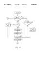
- FIG. 4is a flow chart depicting the operational steps of the controller of FIG. 3.
- FIG. 1there is shown an infusion system that is equipped with an infusion liquid container 2.
- a drip chamber 3communicates with, and receives fluid from the infusion liquid container 2.
- An infusion tube 4in turn, communicates with the drip chamber 3 and receives fluid therefrom.
- the infusion tube 4passes through an infusion pump 5 which controls the rate at which fluid flows through the infusion tube 4.
- the infusion liquid container 2 and infusion pump 5are supported by an infusion stand 1.
- a drip monitoring device 6is attached to the drip chamber 3.
- a controller(not shown) controls the operation of the infusion pump and is preferably incorporated into the infusion pump 5.
- the drip monitoring device 6 and controllerinterface through a cable 7.
- the infusion pump 5 as shown in FIG. 2is provided with a plurality of horizontally movable finger members 8 disposed in a multi-layered fashion.
- a plurality of eccentric cams 10, one for each finger member 8,are pivotally stacked on a rotatable drive shaft 9.
- the eccentric cams 10rotate together with the drive shaft 9.
- the finger members 8are constructed so as to carry out peristaltic movements in line with the rotation of the drive shaft 9 and eccentric cams 10. This motion causes the finger members 8 to press against the infusion tube 4.
- Pressure plate 11limits the movement of the infusion tube 4 and, together with the finger members 8, acts to compress the infusion tube 4 thereby transferring the infusion fluid in the tube 4 downward.
- the upper end of the drive shaft 9is connected to a motor 13 through a transmission mechanism 12.
- the transmission mechanismincludes a worm gear 12a; engaged with the worm gear 12a is a gear 12b.
- An encoder 14is attached to the drive shaft 9 while a rotation position detector 15 is aligned with the encoder
- the drip monitoring device 6 as shown in FIG. 3has a flow sensor 16 which detects fluid drops 25 entering the drip chamber 3.
- the flow sensor 16is a photo coupler consisting of a light-emitting element 16a and light-receiving element 16b which are disposed in a casing 17.
- the casing 17is attached to the drip chamber 3 so that the drip chamber 3 is positioned between the light-emitting element 16a and light-receiving element 16b.
- a drop of fluid 25passes through the drip chamber 3 it passes between the light-emitting element 16a and light-receiving element 16b.
- the intensity of light received by the light-receiving element 16bis reduced and a drop is thereby detected.
- the flow sensor 16generates an electrical signal based on the light intensity received by the light-receiving element 16b. Typically, a reduction in light intensity results in a reduction in the voltage of the electrical signal.
- the flow sensor 16is electrically coupled to the controller 22 which is typically a microcomputer and is usually incorporated into the infusion pump.
- a motion sensor 18 for detecting swaying or vibration of the drip chamber 3is disposed in the drip monitoring device 6. Because the drip monitor device 6 is attached to the drip chamber 3, any movement of the drip chamber 3 results in a corresponding movement of the motion sensor 18.
- the motion sensor 18includes a vibration detector 20. In an alternate configuration the motion sensor 18 also includes a vibration generator 21 and a metallic shim 19 positioned between the vibration detector 20 and the vibration generator 21.
- the vibration detector 20 and a vibration generator 21are preferably piezoelectric ceramic elements.
- the motion sensor 18is electrically coupled to the controller 22.
- the voltage level of the electrical signal generated by the flow sensor 16is monitored by a setting controller 23, contained in the controller 22. Based on the fluctuation in the voltage level of the electrical signal caused by fluid drops passing between the light emitting element 16a and the light receiving element 16b, the setting controller 23 counts the number of drops entering the drip chamber for a set period of time. The setting controller 23 then calculates the volume flow rate of fluid into the drip chamber 3 and, based on this calculation, sets the number of revolutions of the motor 13 which, in turn, sets the infusion volume flow rate of the infusion pump 5.
- Movement of the drip chambercauses a corresponding movement or vibration of the vibration detector 20.
- the frequency of vibration of the vibration detector 20 due to drip-chamber movementis generally low, as for example 10 Hz.
- the movement of the vibration detector 20,in turn, produces an electrical signal whose voltage level fluctuates with the frequency of vibration of the vibration detector 20.
- the vibration generator 21is used to verify the operation of the vibration detector 20.
- the vibration generator 21is forced to vibrate at a known frequency, typically 60 Hz, through the application of an AC voltage signal.
- the vibration of the vibration generator 21is transmitted to the vibration detector 20 through the shim 19. If operating properly, the vibration detector 20 vibrates at the same frequency of the vibration generator 21 and, again, produces a corresponding voltage.
- the maintaining controlleris programmed to distinguish voltages indicating drip-chamber movement, i.e., voltages associated with frequencies around 10 Hz, from voltages indicating a stationary drip chamber, i.e., the voltage associated with a frequency of around 0 Hz for a motion sensor 18 consisting only of a vibration detector 20 and the voltage associated with a frequency of around 60 Hz for a motion sensor 18 which includes the vibration generator 21 and the shim 19.
- the maintaining controller 24overrides the setting controller 23 and the number of revolutions of the motor 13 remains as set immediately prior to the detection of drip-chamber movement. Otherwise the setting controller 23 sets the number of revolutions of the motor 13 so that the fluid-flow rate through the infusion pump 5 matches the fluid-flow rate through the drip chamber 3. While the setting controller 23 and the maintaining controller 24 are described as separate components of the controller 22, their functions may actually be performed by a single component, as for example a programmed microprocessor.
- the controllerperforms a series of steps as shown in FIG. 4 that determines the volume flow rate of the infusion pump.
- step S1operation of the infusion pump is commenced.
- step S2the controller determines whether the signal it receives from the motion sensor indicates that drip-chamber movement has occurred. If drip-chamber movement has not occurred, in step S3 the controller determines, based on the signals received from the flow sensor, whether drops (D) are being detected by the flow sensor.
- step S4the controller counts the number of drops (Nd) for a fixed period of time, e.g., 100 msec.
- step S6the controller, having calculated the infusion volume in the drip chamber, calculates the number of revolutions (RN) of the motor necessary to set the infusion volume of the infusion pump to match that of the drip chamber.
- step S7the controller sends a control signal to the infusion-pump motor to set the number of revolutions of the motor to match that calculated in step S6. Thereafter, the process is returned to step S2.
- step S3when no drops are detected for a fixed period of time, an infusion malfunction is issued.
- step S8the controller sets the number of revolutions of the motor in step S7 to zero, thereby causing the motor to a stop.
- step S2when drip-chamber movement is detected and infusion has just commenced, the controller sets the number of revolutions of the motor in step S7 to a predetermined value as set in step S9.
- the predetermined valueis typically programmed into the controller.
Landscapes
- Health & Medical Sciences (AREA)
- Physics & Mathematics (AREA)
- Fluid Mechanics (AREA)
- Biomedical Technology (AREA)
- Hematology (AREA)
- Vascular Medicine (AREA)
- Engineering & Computer Science (AREA)
- Anesthesiology (AREA)
- Veterinary Medicine (AREA)
- Heart & Thoracic Surgery (AREA)
- General Physics & Mathematics (AREA)
- Life Sciences & Earth Sciences (AREA)
- Animal Behavior & Ethology (AREA)
- General Health & Medical Sciences (AREA)
- Public Health (AREA)
- Electromagnetism (AREA)
- Infusion, Injection, And Reservoir Apparatuses (AREA)
Abstract
Description
Claims (18)
Priority Applications (1)
| Application Number | Priority Date | Filing Date | Title |
|---|---|---|---|
| US08/872,843US5899665A (en) | 1997-06-11 | 1997-06-11 | Method and apparatus for controlling infusion volume |
Applications Claiming Priority (1)
| Application Number | Priority Date | Filing Date | Title |
|---|---|---|---|
| US08/872,843US5899665A (en) | 1997-06-11 | 1997-06-11 | Method and apparatus for controlling infusion volume |
Publications (1)
| Publication Number | Publication Date |
|---|---|
| US5899665Atrue US5899665A (en) | 1999-05-04 |
Family
ID=25360411
Family Applications (1)
| Application Number | Title | Priority Date | Filing Date |
|---|---|---|---|
| US08/872,843Expired - LifetimeUS5899665A (en) | 1997-06-11 | 1997-06-11 | Method and apparatus for controlling infusion volume |
Country Status (1)
| Country | Link |
|---|---|
| US (1) | US5899665A (en) |
Cited By (85)
| Publication number | Priority date | Publication date | Assignee | Title |
|---|---|---|---|---|
| US20040171994A1 (en)* | 2002-11-14 | 2004-09-02 | Goldberg Barry A. | Drip rate monitor for intravenous infusion set |
| US20050267401A1 (en)* | 2004-05-25 | 2005-12-01 | Sherwood Services, Ag. | Safety interlock system for an enteral feeding pump |
| US20060004327A1 (en)* | 2002-09-26 | 2006-01-05 | Sherwood Services Ag | Safety interlock system for an enteral feeding pump |
| US6985870B2 (en) | 2002-01-11 | 2006-01-10 | Baxter International Inc. | Medication delivery system |
| US20060265246A1 (en)* | 2005-05-10 | 2006-11-23 | Cardinal Health 303, Inc. | Medication safety system featuring a multiplexed RFID interrogator panel |
| USD602387S1 (en)* | 2008-11-07 | 2009-10-20 | Industrial Technology Research Institute | Wireless drip monitoring apparatus |
| US8234128B2 (en) | 2002-04-30 | 2012-07-31 | Baxter International, Inc. | System and method for verifying medical device operational parameters |
| US20130310990A1 (en)* | 2011-12-21 | 2013-11-21 | Deka Products Limited Partnership | System, Method, and Apparatus for Monitoring, Regulating, or Controlling Fluid Flow |
| US8622979B2 (en) | 2010-10-19 | 2014-01-07 | Baxter Healthcare S.A. | Infusion system using optical imager for controlling flow and method thereof |
| US8775196B2 (en) | 2002-01-29 | 2014-07-08 | Baxter International Inc. | System and method for notification and escalation of medical data |
| CN104014026A (en)* | 2014-05-28 | 2014-09-03 | 苏州瓦屋物联网科技有限公司 | Fluid infusion device based on acceleration flow detection |
| CN104014049A (en)* | 2014-06-25 | 2014-09-03 | 深圳市万聚源科技有限公司 | Control system and control method of infusion pump |
| CN104014046A (en)* | 2014-05-28 | 2014-09-03 | 苏州瓦屋物联网科技有限公司 | Intelligent drip control device based on vibration sensing monitoring |
| CN104027864A (en)* | 2014-06-15 | 2014-09-10 | 苏州瓦屋物联网科技有限公司 | Squeeze infusion device with function of pressure detection |
| US20140330205A1 (en)* | 2012-09-27 | 2014-11-06 | Shenzhen Wanjuyuan Technology Co., Ltd. | Intelligent infusion pump |
| US9128051B2 (en) | 2010-10-19 | 2015-09-08 | Baxter International Inc. | Optical imaging system for air bubble and empty bag detection in an infusion tube |
| US9134735B2 (en) | 2011-09-30 | 2015-09-15 | Hospira, Inc. | Intravenous flow rate controller |
| US9144644B2 (en) | 2011-08-02 | 2015-09-29 | Baxter International Inc. | Infusion pump with independently controllable valves and low power operation and methods thereof |
| US9151646B2 (en) | 2011-12-21 | 2015-10-06 | Deka Products Limited Partnership | System, method, and apparatus for monitoring, regulating, or controlling fluid flow |
| USD745661S1 (en) | 2013-11-06 | 2015-12-15 | Deka Products Limited Partnership | Apparatus to control fluid flow through a tube |
| US9234850B2 (en) | 2013-03-14 | 2016-01-12 | Baxter International Inc. | Drip chamber with integrated optics |
| USD749206S1 (en) | 2013-11-06 | 2016-02-09 | Deka Products Limited Partnership | Apparatus to control fluid flow through a tube |
| USD751689S1 (en) | 2013-11-06 | 2016-03-15 | Deka Products Limited Partnership | Apparatus to control fluid flow through a tube |
| USD751690S1 (en) | 2013-11-06 | 2016-03-15 | Deka Products Limited Partnership | Apparatus to control fluid flow through a tube |
| USD752209S1 (en) | 2013-11-06 | 2016-03-22 | Deka Products Limited Partnership | Apparatus to control fluid flow through a tube |
| US9352081B2 (en) | 2013-03-14 | 2016-05-31 | Baxter International Inc. | Drip chamber with hydrophobic interior surface |
| US9435455B2 (en) | 2011-12-21 | 2016-09-06 | Deka Products Limited Partnership | System, method, and apparatus for monitoring, regulating, or controlling fluid flow |
| WO2016160527A1 (en)* | 2015-04-01 | 2016-10-06 | Becton, Dickinson And Company | Iv flow management systems and methods |
| US9476825B2 (en) | 2010-10-19 | 2016-10-25 | Baxter International Inc. | Optical imaging system with multiple imaging channel optical sensing |
| US9724465B2 (en) | 2011-12-21 | 2017-08-08 | Deka Products Limited Partnership | Flow meter |
| US9746093B2 (en) | 2011-12-21 | 2017-08-29 | Deka Products Limited Partnership | Flow meter and related system and apparatus |
| US9746094B2 (en) | 2011-12-21 | 2017-08-29 | Deka Products Limited Partnership | Flow meter having a background pattern with first and second portions |
| US9759343B2 (en) | 2012-12-21 | 2017-09-12 | Deka Products Limited Partnership | Flow meter using a dynamic background image |
| US9915523B2 (en) | 2010-06-17 | 2018-03-13 | Koninklijke Philips N.V. | System for monitoring the position of a tube's distal end relative to a blood vessel |
| US10016554B2 (en) | 2008-07-09 | 2018-07-10 | Baxter International Inc. | Dialysis system including wireless patient data |
| US10022498B2 (en) | 2011-12-16 | 2018-07-17 | Icu Medical, Inc. | System for monitoring and delivering medication to a patient and method of using the same to minimize the risks associated with automated therapy |
| US10061899B2 (en) | 2008-07-09 | 2018-08-28 | Baxter International Inc. | Home therapy machine |
| US10105899B2 (en) | 2015-03-26 | 2018-10-23 | Becton, Dickinson And Company | IV membrane attachment systems and methods |
| US10166328B2 (en) | 2013-05-29 | 2019-01-01 | Icu Medical, Inc. | Infusion system which utilizes one or more sensors and additional information to make an air determination regarding the infusion system |
| US10173008B2 (en) | 2002-01-29 | 2019-01-08 | Baxter International Inc. | System and method for communicating with a dialysis machine through a network |
| US10201667B2 (en) | 2015-03-26 | 2019-02-12 | Becton, Dickinson And Company | IV membrane attachment systems and methods |
| US10228683B2 (en) | 2011-12-21 | 2019-03-12 | Deka Products Limited Partnership | System, method, and apparatus for monitoring, regulating, or controlling fluid flow |
| US10232130B2 (en) | 2015-03-26 | 2019-03-19 | Becton, Dickinson And Company | Anti-run dry membrane |
| US10342917B2 (en) | 2014-02-28 | 2019-07-09 | Icu Medical, Inc. | Infusion system and method which utilizes dual wavelength optical air-in-line detection |
| US10347374B2 (en) | 2008-10-13 | 2019-07-09 | Baxter Corporation Englewood | Medication preparation system |
| USD854145S1 (en) | 2016-05-25 | 2019-07-16 | Deka Products Limited Partnership | Apparatus to control fluid flow through a tube |
| US10430761B2 (en) | 2011-08-19 | 2019-10-01 | Icu Medical, Inc. | Systems and methods for a graphical interface including a graphical representation of medical data |
| JP2019177131A (en)* | 2018-03-30 | 2019-10-17 | 株式会社ジェイ・エム・エス | Flow volume monitoring device, infusion device and abnormality notification method |
| US10463788B2 (en) | 2012-07-31 | 2019-11-05 | Icu Medical, Inc. | Patient care system for critical medications |
| US10488848B2 (en) | 2011-12-21 | 2019-11-26 | Deka Products Limited Partnership | System, method, and apparatus for monitoring, regulating, or controlling fluid flow |
| US10552577B2 (en) | 2012-08-31 | 2020-02-04 | Baxter Corporation Englewood | Medication requisition fulfillment system and method |
| US10578474B2 (en) | 2012-03-30 | 2020-03-03 | Icu Medical, Inc. | Air detection system and method for detecting air in a pump of an infusion system |
| US10596316B2 (en) | 2013-05-29 | 2020-03-24 | Icu Medical, Inc. | Infusion system and method of use which prevents over-saturation of an analog-to-digital converter |
| US10635784B2 (en) | 2007-12-18 | 2020-04-28 | Icu Medical, Inc. | User interface improvements for medical devices |
| CN111093728A (en)* | 2017-09-27 | 2020-05-01 | T.J.史密夫及内修有限公司 | Device Operation Monitoring and Control in Wound Treatment Systems |
| US10646405B2 (en) | 2012-10-26 | 2020-05-12 | Baxter Corporation Englewood | Work station for medical dose preparation system |
| US10656894B2 (en) | 2017-12-27 | 2020-05-19 | Icu Medical, Inc. | Synchronized display of screen content on networked devices |
| US10702689B2 (en) | 2015-03-26 | 2020-07-07 | Becton, Dickinson And Company | Auto-stop vent plug |
| US10818387B2 (en) | 2014-12-05 | 2020-10-27 | Baxter Corporation Englewood | Dose preparation data analytics |
| US10850024B2 (en) | 2015-03-02 | 2020-12-01 | Icu Medical, Inc. | Infusion system, device, and method having advanced infusion features |
| USD905848S1 (en) | 2016-01-28 | 2020-12-22 | Deka Products Limited Partnership | Apparatus to control fluid flow through a tube |
| US10874793B2 (en) | 2013-05-24 | 2020-12-29 | Icu Medical, Inc. | Multi-sensor infusion system for detecting air or an occlusion in the infusion system |
| US10971257B2 (en) | 2012-10-26 | 2021-04-06 | Baxter Corporation Englewood | Image acquisition for medical dose preparation system |
| US11107574B2 (en) | 2014-09-30 | 2021-08-31 | Baxter Corporation Englewood | Management of medication preparation with formulary management |
| US11135360B1 (en) | 2020-12-07 | 2021-10-05 | Icu Medical, Inc. | Concurrent infusion with common line auto flush |
| US11246985B2 (en) | 2016-05-13 | 2022-02-15 | Icu Medical, Inc. | Infusion pump system and method with common line auto flush |
| US11278671B2 (en) | 2019-12-04 | 2022-03-22 | Icu Medical, Inc. | Infusion pump with safety sequence keypad |
| US11291762B2 (en)* | 2018-10-15 | 2022-04-05 | Carefusion 303, Inc. | Microdrop drip chamber |
| US11324888B2 (en) | 2016-06-10 | 2022-05-10 | Icu Medical, Inc. | Acoustic flow sensor for continuous medication flow measurements and feedback control of infusion |
| US11344668B2 (en) | 2014-12-19 | 2022-05-31 | Icu Medical, Inc. | Infusion system with concurrent TPN/insulin infusion |
| US11344673B2 (en) | 2014-05-29 | 2022-05-31 | Icu Medical, Inc. | Infusion system and pump with configurable closed loop delivery rate catch-up |
| US11367533B2 (en) | 2014-06-30 | 2022-06-21 | Baxter Corporation Englewood | Managed medical information exchange |
| USD964563S1 (en) | 2019-07-26 | 2022-09-20 | Deka Products Limited Partnership | Medical flow clamp |
| US11495334B2 (en) | 2015-06-25 | 2022-11-08 | Gambro Lundia Ab | Medical device system and method having a distributed database |
| US11516183B2 (en) | 2016-12-21 | 2022-11-29 | Gambro Lundia Ab | Medical device system including information technology infrastructure having secure cluster domain supporting external domain |
| US11575673B2 (en) | 2014-09-30 | 2023-02-07 | Baxter Corporation Englewood | Central user management in a distributed healthcare information management system |
| US11744935B2 (en) | 2016-01-28 | 2023-09-05 | Deka Products Limited Partnership | Apparatus for monitoring, regulating, or controlling fluid flow |
| US11839741B2 (en) | 2019-07-26 | 2023-12-12 | Deka Products Limited Partneship | Apparatus for monitoring, regulating, or controlling fluid flow |
| US11883361B2 (en) | 2020-07-21 | 2024-01-30 | Icu Medical, Inc. | Fluid transfer devices and methods of use |
| US11948112B2 (en) | 2015-03-03 | 2024-04-02 | Baxter Corporation Engelwood | Pharmacy workflow management with integrated alerts |
| US12098738B2 (en) | 2011-12-21 | 2024-09-24 | Deka Products Limited Partnership | System, method, and apparatus for clamping |
| US12263294B2 (en) | 2016-09-28 | 2025-04-01 | T.J.Smith And Nephew, Limited | Systems and methods for operating negative pressure wound therapy devices |
| US12350233B2 (en) | 2021-12-10 | 2025-07-08 | Icu Medical, Inc. | Medical fluid compounding systems with coordinated flow control |
| USD1091564S1 (en) | 2021-10-13 | 2025-09-02 | Icu Medical, Inc. | Display screen or portion thereof with graphical user interface for a medical device |
| US12412644B2 (en) | 2014-10-24 | 2025-09-09 | Baxter Corporation Englewood | Automated exchange of healthcare information for fulfillment of medication doses |
Citations (2)
| Publication number | Priority date | Publication date | Assignee | Title |
|---|---|---|---|---|
| US4786800A (en)* | 1984-12-11 | 1988-11-22 | Baxter International Inc. | Fluid drop detection and discrimination system |
| US4857048A (en)* | 1987-05-29 | 1989-08-15 | Hewlett-Packard Company | IV pump and disposable flow chamber with flow control |
- 1997
- 1997-06-11USUS08/872,843patent/US5899665A/ennot_activeExpired - Lifetime
Patent Citations (2)
| Publication number | Priority date | Publication date | Assignee | Title |
|---|---|---|---|---|
| US4786800A (en)* | 1984-12-11 | 1988-11-22 | Baxter International Inc. | Fluid drop detection and discrimination system |
| US4857048A (en)* | 1987-05-29 | 1989-08-15 | Hewlett-Packard Company | IV pump and disposable flow chamber with flow control |
Cited By (176)
| Publication number | Priority date | Publication date | Assignee | Title |
|---|---|---|---|---|
| US7668731B2 (en) | 2002-01-11 | 2010-02-23 | Baxter International Inc. | Medication delivery system |
| US6985870B2 (en) | 2002-01-11 | 2006-01-10 | Baxter International Inc. | Medication delivery system |
| US10173008B2 (en) | 2002-01-29 | 2019-01-08 | Baxter International Inc. | System and method for communicating with a dialysis machine through a network |
| US8775196B2 (en) | 2002-01-29 | 2014-07-08 | Baxter International Inc. | System and method for notification and escalation of medical data |
| US10556062B2 (en) | 2002-01-29 | 2020-02-11 | Baxter International Inc. | Electronic medication order transfer and processing methods and apparatus |
| US8234128B2 (en) | 2002-04-30 | 2012-07-31 | Baxter International, Inc. | System and method for verifying medical device operational parameters |
| US7537579B2 (en) | 2002-09-26 | 2009-05-26 | Covidien Ag | Safety interlock system for an enteral feeding pump |
| US20060004327A1 (en)* | 2002-09-26 | 2006-01-05 | Sherwood Services Ag | Safety interlock system for an enteral feeding pump |
| US7190275B2 (en)* | 2002-11-14 | 2007-03-13 | Goldberg Barry A | Drip rate monitor for intravenous infusion set |
| US20040171994A1 (en)* | 2002-11-14 | 2004-09-02 | Goldberg Barry A. | Drip rate monitor for intravenous infusion set |
| US20050267401A1 (en)* | 2004-05-25 | 2005-12-01 | Sherwood Services, Ag. | Safety interlock system for an enteral feeding pump |
| US7976508B2 (en)* | 2005-05-10 | 2011-07-12 | Carefusion 303, Inc. | Medication safety system featuring a multiplexed RFID interrogator panel |
| US20110241878A1 (en)* | 2005-05-10 | 2011-10-06 | Carefusion 303, Inc. | Medication safety system |
| US20060265246A1 (en)* | 2005-05-10 | 2006-11-23 | Cardinal Health 303, Inc. | Medication safety system featuring a multiplexed RFID interrogator panel |
| US10635784B2 (en) | 2007-12-18 | 2020-04-28 | Icu Medical, Inc. | User interface improvements for medical devices |
| US10646634B2 (en) | 2008-07-09 | 2020-05-12 | Baxter International Inc. | Dialysis system and disposable set |
| US11311658B2 (en) | 2008-07-09 | 2022-04-26 | Baxter International Inc. | Dialysis system having adaptive prescription generation |
| US10016554B2 (en) | 2008-07-09 | 2018-07-10 | Baxter International Inc. | Dialysis system including wireless patient data |
| US10061899B2 (en) | 2008-07-09 | 2018-08-28 | Baxter International Inc. | Home therapy machine |
| US10068061B2 (en) | 2008-07-09 | 2018-09-04 | Baxter International Inc. | Home therapy entry, modification, and reporting system |
| US10095840B2 (en) | 2008-07-09 | 2018-10-09 | Baxter International Inc. | System and method for performing renal therapy at a home or dwelling of a patient |
| US11918721B2 (en) | 2008-07-09 | 2024-03-05 | Baxter International Inc. | Dialysis system having adaptive prescription management |
| US10224117B2 (en) | 2008-07-09 | 2019-03-05 | Baxter International Inc. | Home therapy machine allowing patient device program selection |
| US10272190B2 (en) | 2008-07-09 | 2019-04-30 | Baxter International Inc. | Renal therapy system including a blood pressure monitor |
| US10347374B2 (en) | 2008-10-13 | 2019-07-09 | Baxter Corporation Englewood | Medication preparation system |
| USD602387S1 (en)* | 2008-11-07 | 2009-10-20 | Industrial Technology Research Institute | Wireless drip monitoring apparatus |
| US9915523B2 (en) | 2010-06-17 | 2018-03-13 | Koninklijke Philips N.V. | System for monitoring the position of a tube's distal end relative to a blood vessel |
| US9603999B2 (en) | 2010-10-19 | 2017-03-28 | Baxter International Inc. | Infusion system using optical imager for controlling flow and method thereof |
| US11583630B2 (en) | 2010-10-19 | 2023-02-21 | Baxter International Inc. | Optical imaging system with multiple imaging channel optical sensing |
| US10226574B2 (en) | 2010-10-19 | 2019-03-12 | Baxter International Inc. | Infusion system using optical imager for controlling flow and method thereof |
| US8622979B2 (en) | 2010-10-19 | 2014-01-07 | Baxter Healthcare S.A. | Infusion system using optical imager for controlling flow and method thereof |
| US11529465B2 (en) | 2010-10-19 | 2022-12-20 | Baxter International Inc. | Infusion system using optical imager for controlling flow and method thereof |
| US10220140B2 (en) | 2010-10-19 | 2019-03-05 | Baxter International Inc. | Infusion system using optical imager for controlling flow and method thereof |
| US9128051B2 (en) | 2010-10-19 | 2015-09-08 | Baxter International Inc. | Optical imaging system for air bubble and empty bag detection in an infusion tube |
| US10406284B2 (en) | 2010-10-19 | 2019-09-10 | Baxter International Inc. | Optical imaging system with multiple imaging channel optical sensing |
| US9476825B2 (en) | 2010-10-19 | 2016-10-25 | Baxter International Inc. | Optical imaging system with multiple imaging channel optical sensing |
| US11571512B2 (en) | 2010-10-19 | 2023-02-07 | Baxter International Inc. | Infusion system using optical imager for controlling flow and method thereof |
| US9144644B2 (en) | 2011-08-02 | 2015-09-29 | Baxter International Inc. | Infusion pump with independently controllable valves and low power operation and methods thereof |
| US10006454B2 (en) | 2011-08-02 | 2018-06-26 | Baxter International Inc. | Infusion pump with independently controllable valves and low power operation and methods thereof |
| US10865786B2 (en) | 2011-08-02 | 2020-12-15 | Baxter International Inc. | Infusion pump with independently controllable valves and low power operation and methods thereof |
| US10851773B2 (en) | 2011-08-02 | 2020-12-01 | Baxter International Inc. | Infusion pump with independently controllable valves and low power operation and methods thereof |
| US10430761B2 (en) | 2011-08-19 | 2019-10-01 | Icu Medical, Inc. | Systems and methods for a graphical interface including a graphical representation of medical data |
| US12346879B2 (en) | 2011-08-19 | 2025-07-01 | Icu Medical, Inc. | Systems and methods for a graphical interface including a graphical representation of medical data |
| US11004035B2 (en) | 2011-08-19 | 2021-05-11 | Icu Medical, Inc. | Systems and methods for a graphical interface including a graphical representation of medical data |
| US11599854B2 (en) | 2011-08-19 | 2023-03-07 | Icu Medical, Inc. | Systems and methods for a graphical interface including a graphical representation of medical data |
| US11972395B2 (en) | 2011-08-19 | 2024-04-30 | Icu Medical, Inc. | Systems and methods for a graphical interface including a graphical representation of medical data |
| US9134735B2 (en) | 2011-09-30 | 2015-09-15 | Hospira, Inc. | Intravenous flow rate controller |
| US9134736B2 (en) | 2011-09-30 | 2015-09-15 | Hospira, Inc. | Intravenous flow rate controller |
| US10022498B2 (en) | 2011-12-16 | 2018-07-17 | Icu Medical, Inc. | System for monitoring and delivering medication to a patient and method of using the same to minimize the risks associated with automated therapy |
| US11376361B2 (en) | 2011-12-16 | 2022-07-05 | Icu Medical, Inc. | System for monitoring and delivering medication to a patient and method of using the same to minimize the risks associated with automated therapy |
| US9772044B2 (en) | 2011-12-21 | 2017-09-26 | Deka Products Limited Partnership | Flow metering using a difference image for liquid parameter estimation |
| US9372486B2 (en)* | 2011-12-21 | 2016-06-21 | Deka Products Limited Partnership | System, method, and apparatus for monitoring, regulating, or controlling fluid flow |
| US11339887B2 (en) | 2011-12-21 | 2022-05-24 | Deka Products Limited Partnership | Flow meter and related method |
| US11449037B2 (en) | 2011-12-21 | 2022-09-20 | Deka Products Limited Partnership | System, method, and apparatus for monitoring, regulating, or controlling fluid flow |
| US9976665B2 (en) | 2011-12-21 | 2018-05-22 | Deka Products Limited Partnership | Flow meter |
| US11574407B2 (en) | 2011-12-21 | 2023-02-07 | Deka Products Limited Partnership | System, method, and apparatus for monitoring, regulating, or controlling fluid flow |
| US9746094B2 (en) | 2011-12-21 | 2017-08-29 | Deka Products Limited Partnership | Flow meter having a background pattern with first and second portions |
| US9746093B2 (en) | 2011-12-21 | 2017-08-29 | Deka Products Limited Partnership | Flow meter and related system and apparatus |
| US9724467B2 (en) | 2011-12-21 | 2017-08-08 | Deka Products Limited Partnership | Flow meter |
| US9724466B2 (en) | 2011-12-21 | 2017-08-08 | Deka Products Limited Partnership | Flow meter |
| US10088346B2 (en) | 2011-12-21 | 2018-10-02 | Deka Products Limited Partnership | System, method, and apparatus for monitoring, regulating, or controlling fluid flow |
| US20130310990A1 (en)* | 2011-12-21 | 2013-11-21 | Deka Products Limited Partnership | System, Method, and Apparatus for Monitoring, Regulating, or Controlling Fluid Flow |
| US9724465B2 (en) | 2011-12-21 | 2017-08-08 | Deka Products Limited Partnership | Flow meter |
| US10488848B2 (en) | 2011-12-21 | 2019-11-26 | Deka Products Limited Partnership | System, method, and apparatus for monitoring, regulating, or controlling fluid flow |
| US10436342B2 (en) | 2011-12-21 | 2019-10-08 | Deka Products Limited Partnership | Flow meter and related method |
| US10113660B2 (en) | 2011-12-21 | 2018-10-30 | Deka Products Limited Partnership | Flow meter |
| US10894638B2 (en) | 2011-12-21 | 2021-01-19 | Deka Products Limited Partnership | System, method, and apparatus for monitoring, regulating, or controlling fluid flow |
| US9435455B2 (en) | 2011-12-21 | 2016-09-06 | Deka Products Limited Partnership | System, method, and apparatus for monitoring, regulating, or controlling fluid flow |
| US10876868B2 (en) | 2011-12-21 | 2020-12-29 | Deka Products Limited Partnership | System, method, and apparatus for monitoring, regulating, or controlling fluid flow |
| US9856990B2 (en) | 2011-12-21 | 2018-01-02 | Deka Products Limited Partnership | Flow metering using a difference image for liquid parameter estimation |
| US12100507B2 (en) | 2011-12-21 | 2024-09-24 | Deka Products Limited Partnership | System, method, and apparatus for monitoring, regulating, or controlling fluid flow |
| US10228683B2 (en) | 2011-12-21 | 2019-03-12 | Deka Products Limited Partnership | System, method, and apparatus for monitoring, regulating, or controlling fluid flow |
| US11738143B2 (en) | 2011-12-21 | 2023-08-29 | Deka Products Limited Partnership | Flow meier having a valve |
| US11793928B2 (en) | 2011-12-21 | 2023-10-24 | Deka Products Limited Partnership | Flow meter and related method |
| US10718445B2 (en) | 2011-12-21 | 2020-07-21 | Deka Products Limited Partnership | Flow meter having a valve |
| US9151646B2 (en) | 2011-12-21 | 2015-10-06 | Deka Products Limited Partnership | System, method, and apparatus for monitoring, regulating, or controlling fluid flow |
| US10844970B2 (en) | 2011-12-21 | 2020-11-24 | Deka Products Limited Partnership | Flow meter |
| US12098738B2 (en) | 2011-12-21 | 2024-09-24 | Deka Products Limited Partnership | System, method, and apparatus for clamping |
| US10739759B2 (en) | 2011-12-21 | 2020-08-11 | Deka Products Limited Partnership | System, method, and apparatus for monitoring, regulating, or controlling fluid flow |
| US11933650B2 (en) | 2012-03-30 | 2024-03-19 | Icu Medical, Inc. | Air detection system and method for detecting air in a pump of an infusion system |
| US10578474B2 (en) | 2012-03-30 | 2020-03-03 | Icu Medical, Inc. | Air detection system and method for detecting air in a pump of an infusion system |
| US10089443B2 (en) | 2012-05-15 | 2018-10-02 | Baxter International Inc. | Home medical device systems and methods for therapy prescription and tracking, servicing and inventory |
| US11623042B2 (en) | 2012-07-31 | 2023-04-11 | Icu Medical, Inc. | Patient care system for critical medications |
| US12280239B2 (en) | 2012-07-31 | 2025-04-22 | Icu Medical, Inc. | Patient care system for critical medications |
| US10463788B2 (en) | 2012-07-31 | 2019-11-05 | Icu Medical, Inc. | Patient care system for critical medications |
| US10552577B2 (en) | 2012-08-31 | 2020-02-04 | Baxter Corporation Englewood | Medication requisition fulfillment system and method |
| US20140330205A1 (en)* | 2012-09-27 | 2014-11-06 | Shenzhen Wanjuyuan Technology Co., Ltd. | Intelligent infusion pump |
| US9700667B2 (en)* | 2012-09-27 | 2017-07-11 | Shenzhen Wanjuyuan Technology Co., Ltd. | Intelligent infusion pump |
| US10971257B2 (en) | 2012-10-26 | 2021-04-06 | Baxter Corporation Englewood | Image acquisition for medical dose preparation system |
| US10646405B2 (en) | 2012-10-26 | 2020-05-12 | Baxter Corporation Englewood | Work station for medical dose preparation system |
| US9759343B2 (en) | 2012-12-21 | 2017-09-12 | Deka Products Limited Partnership | Flow meter using a dynamic background image |
| US9234850B2 (en) | 2013-03-14 | 2016-01-12 | Baxter International Inc. | Drip chamber with integrated optics |
| US9801996B2 (en) | 2013-03-14 | 2017-10-31 | Baxter International Inc. | Drip chamber with hydrophobic interior surface |
| US10314972B2 (en) | 2013-03-14 | 2019-06-11 | Baxter International Inc. | Drip chamber with hydrophobic interior surface |
| US10429312B2 (en) | 2013-03-14 | 2019-10-01 | Baxter International Inc. | Drip chamber with integrated optics |
| US11013860B2 (en) | 2013-03-14 | 2021-05-25 | Baxter International Inc. | Drip chamber with hydrophobic interior surface |
| US11255795B2 (en) | 2013-03-14 | 2022-02-22 | Baxter International Inc. | Drip chamber with integrated optics |
| US9352081B2 (en) | 2013-03-14 | 2016-05-31 | Baxter International Inc. | Drip chamber with hydrophobic interior surface |
| US10874793B2 (en) | 2013-05-24 | 2020-12-29 | Icu Medical, Inc. | Multi-sensor infusion system for detecting air or an occlusion in the infusion system |
| US12048831B2 (en) | 2013-05-24 | 2024-07-30 | Icu Medical, Inc. | Multi-sensor infusion system for detecting air or an occlusion in the infusion system |
| US11596737B2 (en) | 2013-05-29 | 2023-03-07 | Icu Medical, Inc. | Infusion system and method of use which prevents over-saturation of an analog-to-digital converter |
| US10596316B2 (en) | 2013-05-29 | 2020-03-24 | Icu Medical, Inc. | Infusion system and method of use which prevents over-saturation of an analog-to-digital converter |
| US11433177B2 (en) | 2013-05-29 | 2022-09-06 | Icu Medical, Inc. | Infusion system which utilizes one or more sensors and additional information to make an air determination regarding the infusion system |
| US10166328B2 (en) | 2013-05-29 | 2019-01-01 | Icu Medical, Inc. | Infusion system which utilizes one or more sensors and additional information to make an air determination regarding the infusion system |
| US12059551B2 (en) | 2013-05-29 | 2024-08-13 | Icu Medical, Inc. | Infusion system and method of use which prevents over-saturation of an analog-to-digital converter |
| USD799025S1 (en) | 2013-11-06 | 2017-10-03 | Deka Products Limited Partnership | Apparatus to control fluid flow through a tube |
| USD745661S1 (en) | 2013-11-06 | 2015-12-15 | Deka Products Limited Partnership | Apparatus to control fluid flow through a tube |
| USD802118S1 (en) | 2013-11-06 | 2017-11-07 | Deka Products Limited Partnership | Apparatus to control fluid flow through a tube |
| USD816829S1 (en) | 2013-11-06 | 2018-05-01 | Deka Products Limited Partnership | Apparatus to control fluid flow through a tube |
| USD752209S1 (en) | 2013-11-06 | 2016-03-22 | Deka Products Limited Partnership | Apparatus to control fluid flow through a tube |
| USD751690S1 (en) | 2013-11-06 | 2016-03-15 | Deka Products Limited Partnership | Apparatus to control fluid flow through a tube |
| USD815730S1 (en) | 2013-11-06 | 2018-04-17 | Deka Products Limited Partnership | Apparatus to control fluid flow through a tube |
| USD749206S1 (en) | 2013-11-06 | 2016-02-09 | Deka Products Limited Partnership | Apparatus to control fluid flow through a tube |
| USD813376S1 (en) | 2013-11-06 | 2018-03-20 | Deka Products Limited Partnership | Apparatus to control fluid flow through a tube |
| USD751689S1 (en) | 2013-11-06 | 2016-03-15 | Deka Products Limited Partnership | Apparatus to control fluid flow through a tube |
| US10342917B2 (en) | 2014-02-28 | 2019-07-09 | Icu Medical, Inc. | Infusion system and method which utilizes dual wavelength optical air-in-line detection |
| US12083310B2 (en) | 2014-02-28 | 2024-09-10 | Icu Medical, Inc. | Infusion system and method which utilizes dual wavelength optical air-in-line detection |
| CN104014026A (en)* | 2014-05-28 | 2014-09-03 | 苏州瓦屋物联网科技有限公司 | Fluid infusion device based on acceleration flow detection |
| CN104014046A (en)* | 2014-05-28 | 2014-09-03 | 苏州瓦屋物联网科技有限公司 | Intelligent drip control device based on vibration sensing monitoring |
| US11344673B2 (en) | 2014-05-29 | 2022-05-31 | Icu Medical, Inc. | Infusion system and pump with configurable closed loop delivery rate catch-up |
| CN104027864A (en)* | 2014-06-15 | 2014-09-10 | 苏州瓦屋物联网科技有限公司 | Squeeze infusion device with function of pressure detection |
| CN104014049A (en)* | 2014-06-25 | 2014-09-03 | 深圳市万聚源科技有限公司 | Control system and control method of infusion pump |
| US11367533B2 (en) | 2014-06-30 | 2022-06-21 | Baxter Corporation Englewood | Managed medical information exchange |
| US11107574B2 (en) | 2014-09-30 | 2021-08-31 | Baxter Corporation Englewood | Management of medication preparation with formulary management |
| US11575673B2 (en) | 2014-09-30 | 2023-02-07 | Baxter Corporation Englewood | Central user management in a distributed healthcare information management system |
| US12412644B2 (en) | 2014-10-24 | 2025-09-09 | Baxter Corporation Englewood | Automated exchange of healthcare information for fulfillment of medication doses |
| US10818387B2 (en) | 2014-12-05 | 2020-10-27 | Baxter Corporation Englewood | Dose preparation data analytics |
| US11344668B2 (en) | 2014-12-19 | 2022-05-31 | Icu Medical, Inc. | Infusion system with concurrent TPN/insulin infusion |
| US12115337B2 (en) | 2015-03-02 | 2024-10-15 | Icu Medical, Inc. | Infusion system, device, and method having advanced infusion features |
| US10850024B2 (en) | 2015-03-02 | 2020-12-01 | Icu Medical, Inc. | Infusion system, device, and method having advanced infusion features |
| US11948112B2 (en) | 2015-03-03 | 2024-04-02 | Baxter Corporation Engelwood | Pharmacy workflow management with integrated alerts |
| US10973993B2 (en) | 2015-03-26 | 2021-04-13 | Becton, Dickinson And Company | Anti-run dry membrane |
| US11744941B2 (en) | 2015-03-26 | 2023-09-05 | Becton, Dickinson And Company | IV membrane attachment systems and methods |
| US10702689B2 (en) | 2015-03-26 | 2020-07-07 | Becton, Dickinson And Company | Auto-stop vent plug |
| US10232130B2 (en) | 2015-03-26 | 2019-03-19 | Becton, Dickinson And Company | Anti-run dry membrane |
| US10201667B2 (en) | 2015-03-26 | 2019-02-12 | Becton, Dickinson And Company | IV membrane attachment systems and methods |
| US10926029B2 (en) | 2015-03-26 | 2021-02-23 | Becton, Dickinson And Company | IV membrane attachment systems and methods |
| US10105899B2 (en) | 2015-03-26 | 2018-10-23 | Becton, Dickinson And Company | IV membrane attachment systems and methods |
| US11826557B2 (en) | 2015-03-26 | 2023-11-28 | Becton, Dickinson And Company | Anti-run dry membrane |
| AU2016244168B2 (en)* | 2015-04-01 | 2018-10-25 | Becton, Dickinson And Company | IV flow management systems and methods |
| WO2016160527A1 (en)* | 2015-04-01 | 2016-10-06 | Becton, Dickinson And Company | Iv flow management systems and methods |
| US10646648B2 (en) | 2015-04-01 | 2020-05-12 | Becton, Dickinson And Company | IV flow management systems and methods |
| CN107427634A (en)* | 2015-04-01 | 2017-12-01 | 贝克顿·迪金森公司 | venous flow management system and method |
| US11617831B2 (en) | 2015-04-01 | 2023-04-04 | Becton, Dickinson And Company | IV flow management systems and methods |
| US11495334B2 (en) | 2015-06-25 | 2022-11-08 | Gambro Lundia Ab | Medical device system and method having a distributed database |
| US11744935B2 (en) | 2016-01-28 | 2023-09-05 | Deka Products Limited Partnership | Apparatus for monitoring, regulating, or controlling fluid flow |
| USD905848S1 (en) | 2016-01-28 | 2020-12-22 | Deka Products Limited Partnership | Apparatus to control fluid flow through a tube |
| USD943736S1 (en) | 2016-01-28 | 2022-02-15 | Deka Products Limited Partnership | Apparatus to control fluid flow through a tube |
| US11246985B2 (en) | 2016-05-13 | 2022-02-15 | Icu Medical, Inc. | Infusion pump system and method with common line auto flush |
| US12201811B2 (en) | 2016-05-13 | 2025-01-21 | Icu Medical, Inc. | Infusion pump system and method with common line auto flush |
| USD1060608S1 (en) | 2016-05-25 | 2025-02-04 | Deka Products Limited Partnership | Device to control fluid flow through a tube |
| USD860437S1 (en) | 2016-05-25 | 2019-09-17 | Deka Products Limited Partnership | Apparatus to control fluid flow through a tube |
| USD972718S1 (en) | 2016-05-25 | 2022-12-13 | Deka Products Limited Partnership | Apparatus to control fluid flow through a tube |
| USD854145S1 (en) | 2016-05-25 | 2019-07-16 | Deka Products Limited Partnership | Apparatus to control fluid flow through a tube |
| USD972125S1 (en) | 2016-05-25 | 2022-12-06 | Deka Products Limited Partnership | Apparatus to control fluid flow through a tube |
| US11324888B2 (en) | 2016-06-10 | 2022-05-10 | Icu Medical, Inc. | Acoustic flow sensor for continuous medication flow measurements and feedback control of infusion |
| US12076531B2 (en) | 2016-06-10 | 2024-09-03 | Icu Medical, Inc. | Acoustic flow sensor for continuous medication flow measurements and feedback control of infusion |
| US12263294B2 (en) | 2016-09-28 | 2025-04-01 | T.J.Smith And Nephew, Limited | Systems and methods for operating negative pressure wound therapy devices |
| US11516183B2 (en) | 2016-12-21 | 2022-11-29 | Gambro Lundia Ab | Medical device system including information technology infrastructure having secure cluster domain supporting external domain |
| CN111093728A (en)* | 2017-09-27 | 2020-05-01 | T.J.史密夫及内修有限公司 | Device Operation Monitoring and Control in Wound Treatment Systems |
| US11029911B2 (en) | 2017-12-27 | 2021-06-08 | Icu Medical, Inc. | Synchronized display of screen content on networked devices |
| US11868161B2 (en) | 2017-12-27 | 2024-01-09 | Icu Medical, Inc. | Synchronized display of screen content on networked devices |
| US10656894B2 (en) | 2017-12-27 | 2020-05-19 | Icu Medical, Inc. | Synchronized display of screen content on networked devices |
| US12333201B2 (en) | 2017-12-27 | 2025-06-17 | Icu Medical, Inc. | Synchronized display of screen content on networked devices |
| JP2019177131A (en)* | 2018-03-30 | 2019-10-17 | 株式会社ジェイ・エム・エス | Flow volume monitoring device, infusion device and abnormality notification method |
| US11291762B2 (en)* | 2018-10-15 | 2022-04-05 | Carefusion 303, Inc. | Microdrop drip chamber |
| USD964563S1 (en) | 2019-07-26 | 2022-09-20 | Deka Products Limited Partnership | Medical flow clamp |
| US11839741B2 (en) | 2019-07-26 | 2023-12-12 | Deka Products Limited Partneship | Apparatus for monitoring, regulating, or controlling fluid flow |
| US12268843B2 (en) | 2019-12-04 | 2025-04-08 | Icu Medical, Inc. | Infusion pump with safety sequence keypad |
| US11278671B2 (en) | 2019-12-04 | 2022-03-22 | Icu Medical, Inc. | Infusion pump with safety sequence keypad |
| US12310921B2 (en) | 2020-07-21 | 2025-05-27 | Icu Medical, Inc. | Fluid transfer devices and methods of use |
| US11883361B2 (en) | 2020-07-21 | 2024-01-30 | Icu Medical, Inc. | Fluid transfer devices and methods of use |
| US11135360B1 (en) | 2020-12-07 | 2021-10-05 | Icu Medical, Inc. | Concurrent infusion with common line auto flush |
| US12390586B2 (en) | 2020-12-07 | 2025-08-19 | Icu Medical, Inc. | Concurrent infusion with common line auto flush |
| USD1091564S1 (en) | 2021-10-13 | 2025-09-02 | Icu Medical, Inc. | Display screen or portion thereof with graphical user interface for a medical device |
| US12350233B2 (en) | 2021-12-10 | 2025-07-08 | Icu Medical, Inc. | Medical fluid compounding systems with coordinated flow control |
Similar Documents
| Publication | Publication Date | Title |
|---|---|---|
| US5899665A (en) | Method and apparatus for controlling infusion volume | |
| US4617014A (en) | Dual mode I. V. infusion device | |
| CA1200870A (en) | Intermittent drop detecting method and apparatus | |
| CA1258212A (en) | Dual mode i.v. infusion device with distal sensor | |
| EP0440320A1 (en) | Pumping system | |
| US6532392B1 (en) | Transmitter with software for determining when to initiate diagnostics | |
| US5180287A (en) | Method for monitoring fluid flow from a volumetric pump | |
| US6142008A (en) | Air bubble sensor | |
| EP0248633B1 (en) | Detection of fluid flow faults in the parenteral administration of fluids | |
| MXPA02006732A (en) | Occlusion detection method and system for ambulatory drug infusion pump. | |
| US5039279A (en) | Sensor for detecting fluid flow from a positive displacement pump | |
| EP3859157A1 (en) | Microfluidic pump-based infusion anomaly state detection and control system | |
| WO1993004284A1 (en) | Detecting occlusion of proximal or distal lines of an iv pump | |
| EP0058167A4 (en) | Metering apparatus with downline pressure monitoring system. | |
| WO2004052429A1 (en) | A syringe driver assembly | |
| CN106015893A (en) | Lubricating device with a control unit for operating the lubricating pump | |
| US6339373B1 (en) | Sensor device providing indication of device health | |
| TW202016666A (en) | Monitoring method for lubricating oil injection system that avoids excessive oil injection or insufficient oil injection | |
| EP4004374B1 (en) | Fluid pump | |
| CN116173352B (en) | Automatic transfusion monitoring method and system based on weight monitoring | |
| US10953153B2 (en) | Infusion device and method allowing for detecting a drift in a sensor signal | |
| CN112972803B (en) | Microdialysis system comprising flow feedback device | |
| US4864203A (en) | Diagnostic apparatus | |
| EP1741076B1 (en) | Gas monitor using electrochemical cell and method of operating | |
| JPH11119839A (en) | Pressure control abnormality detection device in semiconductor manufacturing equipment |
Legal Events
| Date | Code | Title | Description |
|---|---|---|---|
| AS | Assignment | Owner name:ALARIS MEDICAL SYSTEMS, INC., CALIFORNIA Free format text:ASSIGNMENT OF ASSIGNORS INTEREST;ASSIGNORS:MAKINO, HIDEO;KATAYAMA, KENJI;TAKEDA, YOSHITAKA;REEL/FRAME:008605/0600 Effective date:19970531 | |
| STCF | Information on status: patent grant | Free format text:PATENTED CASE | |
| AS | Assignment | Owner name:BANKERS TRUST COMPANY, NEW YORK Free format text:SECURITY INTEREST;ASSIGNOR:ALARIS MEDICAL SYSTEMS, INC.;REEL/FRAME:011731/0265 Effective date:20010322 | |
| AS | Assignment | Owner name:IISBC BANK USA, NEW YORK Free format text:SECURITY INTEREST;ASSIGNOR:ALARIS MEDICAL SYSTEMS, INC.;REEL/FRAME:013403/0338 Effective date:20011016 | |
| FPAY | Fee payment | Year of fee payment:4 | |
| AS | Assignment | Owner name:ALARIS MEDICAL SYSTEMS, INC., CALIFORNIA Free format text:CHANGE OF NAME;ASSIGNOR:ALARIS MEDICAL, INC.;REEL/FRAME:014201/0592 Effective date:20030630 Owner name:ALARIS MEDICAL SYSTEMS, INC., CALIFORNIA Free format text:SECURITY AGREEMENT;ASSIGNOR:HSBC BANK USA;REEL/FRAME:014220/0171 Effective date:20030630 Owner name:ALARIS MEDICAL, INC., CALIFORNIA Free format text:MERGER;ASSIGNOR:ALARIS MEDICAL SYSTEMS, INC.;REEL/FRAME:014220/0417 Effective date:20030630 Owner name:CITICORP NORTH AMERICA, INC., NEW YORK Free format text:SECURITY AGREEMENT;ASSIGNOR:ALARIS MEDICAL SYSTEMS, INC.;REEL/FRAME:014220/0315 Effective date:20030630 | |
| AS | Assignment | Owner name:ALARIS MEDICAL SYSTEMS, INC., CALIFORNIA Free format text:RELEASE OF SECURITY AGREEMENT;ASSIGNOR:CITICORP NORTH AMERICA, INC.;REEL/FRAME:015703/0127 Effective date:20040707 | |
| AS | Assignment | Owner name:CARDINAL HEALTH 303, INC., CALIFORNIA Free format text:CHANGE OF NAME;ASSIGNOR:ALARIS MEDICAL SYSTEMS, INC.;REEL/FRAME:016996/0582 Effective date:20041013 | |
| FPAY | Fee payment | Year of fee payment:8 | |
| AS | Assignment | Owner name:CAREFUSION 303, INC.,CALIFORNIA Free format text:CHANGE OF NAME;ASSIGNOR:CARDINAL HEALTH 303, INC.;REEL/FRAME:023800/0598 Effective date:20090801 Owner name:CAREFUSION 303, INC., CALIFORNIA Free format text:CHANGE OF NAME;ASSIGNOR:CARDINAL HEALTH 303, INC.;REEL/FRAME:023800/0598 Effective date:20090801 | |
| FPAY | Fee payment | Year of fee payment:12 |