US5899410A - Aerodynamic body having coplanar joined wings - Google Patents
Aerodynamic body having coplanar joined wingsDownload PDFInfo
- Publication number
- US5899410A US5899410AUS08/764,201US76420196AUS5899410AUS 5899410 AUS5899410 AUS 5899410AUS 76420196 AUS76420196 AUS 76420196AUS 5899410 AUS5899410 AUS 5899410A
- Authority
- US
- United States
- Prior art keywords
- wing
- wings
- joined
- fuselage
- aft
- Prior art date
- Legal status (The legal status is an assumption and is not a legal conclusion. Google has not performed a legal analysis and makes no representation as to the accuracy of the status listed.)
- Expired - Lifetime
Links
Images


Classifications
- B—PERFORMING OPERATIONS; TRANSPORTING
- B64—AIRCRAFT; AVIATION; COSMONAUTICS
- B64C—AEROPLANES; HELICOPTERS
- B64C39/00—Aircraft not otherwise provided for
- B64C39/06—Aircraft not otherwise provided for having disc- or ring-shaped wings
- B64C39/068—Aircraft not otherwise provided for having disc- or ring-shaped wings having multiple wings joined at the tips
Definitions
- the present inventionrelates generally to aerodynamic bodies, such as aircraft, and, more particularly, to aircraft and other aerodynamic bodies having coplanar joined wings which improve their aerodynamic performance and allow improved internal arrangements.
- All successful aircraft designsmust address numerous design parameters in order to provide the necessary lift and thrust to overcome the associated drag and weight of an aircraft so as to fly.
- common design parameterswhich affect the aerodynamic efficiency or performance of an aircraft include the aspect ratio (AR), weight, the lift coefficient, the drag coefficient and stability factors (typically indicated by yawing, pitching, and rolling moments) both at high speed and low speed conditions.
- the central challenge of aircraft designis to maximize the amount of lift generated by an aircraft for the amount of associated drag, i.e., maximize the lift to drag (L/D) ratio.
- L/Dlift to drag
- shape of the aircraft's wingsalso impacts the distribution of aerodynamic pressure or force over the surface of the wings which, in turn, affects the rotational and structural capabilities and limitations of the resulting aircraft.
- the ARis generally thought to be one of the more important aircraft design parameters and can be computed as follows:
- sweep angle of the wingswhich can be described as the angle between a line drawn a quarter of the way between the leading and trailing edge of a wing and the spanwise or lateral direction. Wings with lower sweep angles generally yield higher lift force components, while wings having greater sweep angles are typically more desirable at flight speeds close to the speed of sound in order delay the onset of undesirable compressibility effects.
- a number of different types of aircrafthave been developed.
- conventional aircraftcan be generally divided into two categories--a cantilever wing type aircraft and a joined wing type aircraft.
- Prior joined wing aircraft configurationsemploy two sets of wings which are rigidly interconnected or joined. As a result, the joined wing structure is self-bracing.
- a cantilever wing structureemploys wings which have no self-bracing feature, but which, instead, extend laterally outward from the fuselage in a manner independent of the other wing.
- a cantilever wing structuremust therefore have stronger supporting struts and, in some instances, requires thicker wings fabricated from stronger materials.
- joined wing aircraftcan have lighter and stiffer wings. Further, joined wing aircraft can also have improved aerodynamic characteristics such as higher span-efficiency factors which result in lower induced drag.
- the Wolkovitch '684 patentdescribes the use of a vertical tail to mount an aft wing higher than a forward wing, thus, forming a triangular braced wing configuration.
- the tailwhile providing inherent stability to the aircraft, must be of fairly rugged construction in order to carry the entire aft wing loads as well as its own load. As a result, the tail would likely be sized thicker than the aerodynamically optimum tail, potentially resulting in a tail-heavy condition. Further, the increased drag introduced by this non-coplanar wing configuration also reduces the L/D ratio.
- the triangular braced wing configuration proposed by the Wolkovitch '684 patentis also configured such that the large forward wing and aft wing dihedral creates a significant amount of wing area when viewed from the side of the aircraft.
- the dihedral angleis the angle between the plane of the wing and the horizontal plane as seen in the front view.
- any side projected area of the wings forward of the center of gravityis directionally destabilizing, although it is at least partially counter-balanced by the side projected area of the aft wing which is stabilizing (like the vertical tail).
- the side projected area of both wingsdoes not provide any aerodynamic benefit and would most likely add to the aircraft's drag without increasing its lift.
- U.S. Pat. No. 4,365,773also issued to Wolkovitch entitled Joined Wing Aircraft also describes a joined wing aircraft which employs a tail and a pair of wings.
- the first set of wingsextend outwardly in opposite directions from a medial portion of the fuselage to join the ends of respective ones of a second set of wings which are mounted to the top of the tail and extend downwardly and forward therefrom.
- the wingsare positioned at different planar levels and require the tail to support the aft wings, thereby creating a heavier vertical tail and aft body.
- each of these joined wing aircraft designsstill suffers from several deficiencies which limit the aircraft's performance capabilities.
- an aerodynamic bodysuch as an aircraft, which includes a lengthwise extending fuselage and a pair of coplanar joined wings extending outwardly from opposed sides of the fuselage.
- the pair of coplanar joined wingsare formed by at least two forward wings extending laterally outward and rearward from opposite sides of a forward portion of the fuselage, and at least two aft wings extending laterally outward and forward from opposite sides of a rearward portion of the fuselage.
- Each aft wingis joined to a respective forward wing at a common wingtip to thereby form one of the joined wings.
- the aft wingcan either be joined to the outermost portion of the respective forward wing or to a medial portion of the respective forward wing such that a portion of the forward wing extends outboard of the common wingtip or vice versa.
- the forward and aft wings of the joined wing aircraft of the present inventiondefine respective planes which are mutually coplanar such that the resulting coplanar joined wing aircraft has enhanced aerodynamic and structural properties.
- the aircraftis designed such that expendable objects, such as fuel, and heavier objects, such as air-to-ground weapons, can be carried at or near the center of gravity of the aircraft, while objects with a fixed weight or lighter objects can be removed from the center of gravity of the aircraft.
- the aircraftincludes a crew station which typically has a fixed weight and which is positioned away from the center of gravity of the aircraft and within at least one common wingtip.
- an aircraft according to another embodiment of the present inventioncan define an internal weapons bay within a common wingtip, such as the common wingtip opposite the crew station, for storing weapons, such as relatively lightweight air-to-air weapons, prior to delivery of the weapons during flight of the aircraft.
- the aircraftcan include a fuel tank disposed within the fuselage and surrounding the center of gravity such that the center of gravity of the aircraft will not significantly shift and the aircraft's performance will not be altered as the fuel is expended during the flight of the aircraft.
- the aircraftcan also include landing gear, including centerline landing gear which extends downwardly from the fuselage and outrigger landing gear which extends downwardly from respective ones of the common wingtips.
- the aerodynamic bodysuch as an aircraft, of one advantageous embodiment has variable wing sweep in order to further improve its aerodynamic performance.
- one wing of each coplanar joined wingis fixed in position relative to the fuselage while the other wing is adjustably joined to the fuselage such that the sweep angle defined by the adjustable wing can be controllably varied.
- both the forward and aft wings of a coplanar joined wingcan be adjustably connected to the fuselage such that the entire joined wing can be extended and can be closed in a scissors-like motion to provide variable wing sweep.
- the adjustable connection of one or both wings of the coplanar joined wing to the fuselagegenerally includes a sliding-type connection such that relative position of the fuselage and the adjustable wing(s) can be adjusted by sliding the wing(s) forward and rearward.
- the aerodynamic body of the present inventionsuch as an aircraft, includes at least two wing panels extending outward from the respective ones of the common wingtips. While the wing panels can be integral with and extend outwardly from a respective forward wing, the wing panels can also be adjustably connected to the respective common wingtip such that the sweep angle defined by each wing panel can be controllably varied to provide the variable wing sweep. For example, each wing panel can be controllably rotated within the plane defined by the forward and aft wings of the coplanar joined wing to thereby selectively vary the sweep angle.
- each wing panelcan be provided in a wing-fold configuration, for example, each wing panel can be hingedly connected to the respective common wingtip such that the wing panel can be controllably rotated in an upward direction to a stowed position to facilitate storage of the aerodynamic body.
- the aerodynamic body, such as the aircraft, of the present inventionpreferably includes coplanar joined wings which provide significant aerodynamic and structural advantages.
- the coplanar joined wingscan be positionally varied to provide variable wing sweep, thereby further improving the aerodynamic performance of the aircraft at different operating conditions, such as during takeoff, flight and landing.
- the aircraft of the present inventionallows fixed weight and lighter weight objects, such as a crew station and lighter weapons, to be disposed in the common wingtips of the coplanar joined wings such that heavier items and expendable items, such as fuel, can be disposed at or near the center of gravity of the aircraft, thereby insuring that the aerodynamic performance of the aircraft will not change or degrade as the expendable items are consumed during flight.
- FIG. 1illustrates a perspective view of a coplanar joined wing aircraft.
- FIG. 2illustrates a plan view of a tailless coplanar joined wing aircraft including multiple control surfaces according to.
- FIG. 3illustrates a side view of the embodiment of the coplanar joined wing aircraft illustrated in FIG. 2.
- FIGS. 4A and 4Billustrate one embodiment of the coplanar joined wing aircraft of the present invention in which the coplanar joined wings have a variable sweep option for both wings and define a relatively small sweep angle and a relatively large sweep angle, respectively.
- FIGS. 5A and 5Bare schematic plan views of one embodiment of the coplanar joined wing aircraft of the present invention which illustrate wing panels having variable sweep outer panels which extend outwardly from the common wingtips.
- FIGS. 6A and 6Bare perspective and schematic cross-sectional plan views, respectively, of one embodiment of the coplanar joined wing aircraft of the present invention which includes a crew station and a weapons bay in the common wingtips.
- FIGS. 7A and 7Bare schematic plan views of one embodiment of the coplanar joined wing aircraft of the present invention which illustrate control surfaces on the trailing edges of the forward and aft wings.
- FIGS. 8A and 8Bare schematic plan views of one embodiment of the coplanar joined wing aircraft of the present invention which illustrate movement of either the forward wings alone or the aft wings alone in order to vary the corresponding sweep angle.
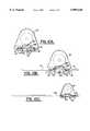
- FIGS. 9A-9Care plan views of one embodiment of a coplanar joined wing missile of the present invention which illustrates the coplanar joined wings in the stowed, partially deployed and fully deployed positions, respectively.
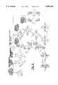
- FIGS. 10A-10Care cross-sectional views taken along line 10--10 of FIGS. 9A-9C, respectively, which illustrate the adjustable connection between the forward wings and the fuselage of the coplanar joined wing missile of one embodiment of the present invention.
- FIG. 11is a schematic diagram illustrating a coplanar joined wing family tree which illustrates some of the fixed and variable wing configurations.
- FIG. 1illustrates a joined wing aircraft 10. While the present invention will be described primarily in conjunction with aircraft, such as airplanes, the present invention is equally applicable to a number of different aerodynamic bodies, such as missiles as shown in FIGS. 9 and 10 and described hereinafter.
- a joined wing aircraftincludes a lengthwise extending fuselage 12, forward wings 14 which are preferably aft swept and aft wings 16 which are preferably forward swept. The wings are attached to the fuselage at their respective wingroots.
- the aft wings 16are positioned aft of the forward wings 14, but on substantially the same planar level relative to the forward wings.
- each of the wingsis relatively flat when viewed from the side as shown in FIG. 3.
- each wingdefines a respective planar surface which extends through the leading and trailing edges of the wing and which is mutually coplanar with the planar surfaces defined by each of the other wings.
- the forward wing 14 and aft wing 16 on each side of the fuselage 12are each angled or swept, at either the same or different angles, to extend toward the other and to join at a common wingtip 13, thereby forming a coplanar joined wing on each side of the fuselage.
- the outermost portions 15B, 17B of the forward and aft wingsare joined in the embodiment of FIGS. 1-3.
- the structurecan also include an additional wing panel 14A, 16A positioned at a common wing tip 13 to extend therebeyond.
- the extra panel 14A, 16Acan be positioned at a number of locations so that it is aligned with aft wing forward wing or variable sweep. See e.g. configurations noted in FIG.
- FIG. 11illustrates some of the alternative wing configurations and illustrates wings or wing portions which have been both speckled and cross-hatched to show some alternative wing positions.
- one of the forward or aft wingis stationary or fixed (indicated as white) and the other wing is moveable between a first position (indicated as shaded or speckled pattern) and a second position (indicated by a cross-hatch pattern).
- the aircraft 10includes an additional wing panel 14A which extends beyond or outboard of the common wingtip 13.
- the attachmentcan be either fixed or variable thus providing a fixed wing geometry or a variable sweep wing geometry.
- the additional wing panel 14Acan be integral with a common wing tip 13 and extend at the same angle as respective ones of the forward wing 14 or the aft wing 16.
- the wing panels 14Acan be joined, typically in an adjustable manner, to a common wingtip 13 as shown in FIGS. 5A and 5B (FIG. 11).
- the wing panels 14A, 16Acan be rotatably connected to the common wingtip such that the wing panels can be rotated within the plane defined by the forward and aft wings to vary sweep angle of the wing panels as shown by the dashed lines in FIGS. 5A and 5B.
- the sweep angle of the wing panelsis selectively controlled during flight, such as by a flight control computer which operates either automatically or based on pilot input, in order to optimize the aerodynamic performance of the aircraft for different flight conditions.
- the wing panelscan be hingedly connected to the respective common wingtips such that the wing panels can be rotated upwardly to a stowed position following flight to facilitate storage of the aircraft.
- Examples of known wing panel connections which would secure the wing panel to the common wingtip as in FIG. 5includes a pin and bearing arrangement similar to those employed on B-1, F-111, or Soviet aircraft.
- the wing panelscould be rotated in any number of manners such as via a linear or rotary actuator.
- the location of the center of gravity (Cg) of an aircraftis an important factor in aircraft stability since the various forces and moments of the aircraft must be balanced about the Cg in order for an aircraft to be stable.
- the stability of an aircraftwas hindered by changes in the location of the Cg during flight as bombs are released and fuel is consumed.
- the aircraft 10 of the present inventionis designed such that the Cg is within the fuselage 12 and expendable items and relatively heavy objects are located near the Cg, while lighter and fixed-weight items are mounted or disposed outboard of the fuselage, such as within the common wingtips 13.
- the aircraft 10includes a crew station 20 for housing the crew of the aircraft.
- the crew stationcan resemble the cockpit of a conventional aircraft which includes the controls and other monitors necessary to guide the aircraft. While the crew station can be disposed within the fuselage 12 as shown in FIGS. 1-5, the crew station of one advantageous embodiment is preferably disposed within a common wingtip 13 or an extension of the common wingtip as shown in FIGS. 6A and 6B. As a result, the fixed-weight crew station is moved away from the Cg of the aircraft such that heavier items or expendable items can fill the fuselage.
- FIGS. 1-5the crew station of one advantageous embodiment is preferably disposed within a common wingtip 13 or an extension of the common wingtip as shown in FIGS. 6A and 6B.
- the aircraft and, more particularly, the flight control computer and the control surfacescan be readily configured such that the aircraft responds to the pilot's commands in a conventional fashion, such as by rolling about the crew station as opposed to the Cg of the aircraft, if desired.
- the fuselage 12 of this embodimentcan include a fuel tank 38 for storing the fuel which will be consumed during the flight of the aircraft 10.
- the fuel tankis disposed such that the Cg is near or within the fuel tank.
- the fuselagecan include a weapons bay 39 for storing relatively heavy weapons, such as air-to-surface missiles, and/or bombs, near the Cg such that the stability of the aircraft will not be significantly affected as these heavier weapons are deployed.
- lighter weaponssuch as air-to-air missiles
- an outboard weapons bay 37which is defined in one of the common wingtips, such as the wingtip opposite the crew station 20. Since these weapons are much lighter, however, they can be held within and deployed from a weapons bay remote from the Cg without significantly altering the flight characteristics of the aircraft.
- these lighter missilescan be conveniently mounted on a launch rail attached to a weapons bay door. Thus, when the door is opened, the missiles are rotated into the air stream and released.
- the aircraft 10 of the present inventionalso includes at least one propulsion engine 40.
- the enginecould be mounted in a number of positions, the engine is preferably mounted aft of and central to the aircraft to further balance the craft.
- the propulsion enginecan include, but is not limited to, abducted fan or a turbofan.
- the aircraftalso includes landing gear and, more preferably, includes a tandem centerline landing gear 41, such as employed by the B-52, U2, and AV-8 Harrier aircraft, which extends downwardly from the fuselage 12 and an outrigger landing gear 43 which extends downwardly from the common wingtips 13. During flight, the outrigger landing gear can be retracted into and housed within the common wingtips.
- the aircraft 10can include a tail 18 as shown in FIG. 1, it is preferred that the coplanar joined wing aircraft be configured without a rear vertical tail, i.e., vertically tailless, as shown in FIGS. 2 and 3.
- the tailless designyields an improvement in drag and weight.
- the aircraftcan include a small tail fin(s) to provide a stabilizing effect without introducing large amounts of drag and weight. In any event, it is desired to minimize or replace the tail with other means to stabilize yawing moments. Exemplary methods for achieving this result include, but are not limited to, thrust vectoring or other aerodynamic features such as drag devices extending from the common wingtips 13 (FIG. 2) and the like.
- the coplanar joined wing aircraft 10 of the present inventioncan provide directional stability in a variety of manners such as one or more vertical tails 18 which can include respective rudders, drag rudders and/or thrust vectoring.
- the coplanar joined wing aircraftcan include a single centerline tail or two laterally spaced tails.
- the tailcan be of different sizes, it is preferred that the tail(s) be relatively small to reduce the drag and weight of the aircraft.
- the coplanar joined wing aircraftcan include drag rudders 30e (FIG.
- thrust vectoringalone or in combination with other control surfaces can be used to generate an altered thrust vector to balance a yawing moment, thereby creating a controlled and stabilized force.
- the aircraft 10 of the present inventionpreferably includes control surfaces 30, such as ailerons, elevators and rudders, which operate under control of the flight control computer to control various directional movements.
- control surfaces 30such as ailerons, elevators and rudders, which operate under control of the flight control computer to control various directional movements.
- the angle of attack(and therefore speed) is typically controlled by elevators or elevons.
- These control surfaces wingwill direct the angle of attack of an aircraft, in accordance with their position relative to the forward or aft wing. For example, assuming the control surfaces are positioned on forward wings 14, deflecting these control surfaces downward increases the lift of the wing and causes the nose of the aircraft to pitch upward, while an upward deflection yields the opposite effect.
- control surfaces positioned on aft wings 16the reverse is true.
- lateral control of an aircraftis typically achieved by the differential deployment of the ailerons.
- one aileroncan be deflected downwardly to increase wing lift on the same side as the aileron, while another aileron, positioned on the opposing wing, can be deflected upwardly to reduce lift on that side.
- the aircraftcan include spoilers which project upwardly from the wing in lieu of or in addition to ailerons to produce separation and drag that, in turn, reduces lift.
- a coplanar joined wing aircraft 10 of the present inventioncan include pitch and roll control surfaces 30 positioned on the trailing edges of the forward wings 14 alone, the aft wings 16 alone, or both.
- each wingcan include a single control surface which is deflected in combination with the other control surfaces upon command by the flight control computer to function either as an elevator (moving together) or as an aileron (moving differentially).
- each forward wing 14can include a pair of control surfaces 30 to thereby form an inboard set 30a and an outboard set 30b.
- each aft wing 16can include a pair of control surfaces 30 to thereby form an inboard set 30d and an outboard set 30c.
- the aircraft 10can be controlled in at least two different fashions.
- the inboard set of control surfaces 30a, 30d on both the forward and the aft wings 14, 16can be deployed as elevators and the outboard set on both wings 30b, 30c can be deployed differentially as ailerons.
- control surfaces 30can be activated or deployed, such as by the flight control computer, in different manners to thereby intermix the functions of both pitch and roll among the various control surfaces. This flexibility enhances an aircraft's survivability by providing redundant control.
- the aircraft 10 of the present inventiondeploys the intermixed control surfaces 30 (e.g., FIGS. 4, and 6) to provide a high lift configuration.
- the intermixed control surfaces 30e.g., FIGS. 4, and 6
- selected ones of both forward and aft wing control surfaces 30can be deflected downwardly for landing, while other selected surfaces can be deflected upwardly to control the roll and/or pitch of the aircraft.
- the various control surfacescan be trimmed to provide high lift, while generating balanced moments on the forward and aft wings.
- the coplanar joined wing aircraft of the present inventionsuffers from relatively little, if any, loss of lift compared to the much greater loss associated with conventional wing/tail systems, thereby producing a higher trimmed lift coefficient. Further, it will be appreciated by those of skill in the art that a non-coplanar joined wing's dihedrals yields lift which is normal to the plane of the wing and results in a corresponding loss in high lift.
- the aircrafthas a variable geometry to provide both an optimum subsonic and supersonic wing sweep.
- This variable wing sweep featureallows the L/D ratio to be adjusted to provide good cruise efficiency at both speed conditions. For example, an unswept configuration is generally best for low speed conditions, such as take off, and a swept wing configuration is generally best for high speed conditions.
- this featureallows for increased range, better STOL characteristics and better maneuvering capabilities at higher speeds.
- a coplanar joined wing aircraft 10 of the present inventioncan incorporate variable sweep in a variety of manners, such as by changing the sweep of only one wing while keeping the other wing fixed or by changing the sweep of both wings either independently or in the same manner. Additionally, the sweep angle of only a portion of the wings can be altered, such as the sweep angle defined by a wing panel 14A, 16A positioned outboard of the common wingtip 13 as described above.
- the forward and aft wingsare joined to the fuselage 12 in an adjustable manner such that the sweep angle defined by each of the wings can be controllably altered.
- FIG. 4Ashows an unswept configuration
- FIG. 4Bshows a swept configuration.
- the wingscan have a variety of shapes and sizes and can be positioned so as to have a variety of sweep angles.
- FIG. 4A and 4Bdepicts the aft wing 16 joined to a medial portion of the forward wing 14 to form a common wingtip 13 which is inboard of the wing edge, the aft and forward wings can be joined at their respective wingtips as shown in FIG. 1 without departing from the spirit and scope of the present invention.
- the coplanar joined wing aircraft 10 of this embodimentincludes a scissor mechanism which operates under control of the pilot and/or flight control computer to controllably position the forward and aft wings.
- the forward wings 14are rotatably connected to the fuselage 12 so as to rotate about a pivot point while the aft wings 16 are slidably connected to the fuselage. Therefore, the relative position at which the aft wings extend outwardly from the fuselage can be readily adjusted by controllably sliding the aft wings either forward or rearward relative to the fuselage.
- the movement of the aft wings forward and rearward relative to the fuselagenot only alters the sweep angle of the aft wings, but also moves the forward wings in the same direction so as to correspondingly alter the sweep angle defined by the forward wings.
- the forward and aft wingscan be extended in a low swept condition.
- the forward and aft wingscan be closed into a higher swept condition.
- the aerodynamic bodyis a missile as shown in FIGS. 9 and 10
- the forward and aft wings 14, 16can be closed within the fuselage to facilitate internal storage and or a low drag external carriage.
- the forward wings 14can be rotatably connected to the fuselage 12 so as to rotate about respective pivot points as the aft wings 16 slide forward and rearward
- the scissor mechanismcan be implemented in the variety of other fashions to allow the sweep angle of the forward and/or aft wings to be varied without departing from the spirit and scope of the present invention.
- the aft wingscan be rotatably connected to the fuselage so as to rotate about a pivot point, while the forward wings can be slidably connected to the fuselage such that the forward wings can slide forward and rearward in order to decrease the sweep angle and increase the sweep angle, respectively.
- both the forward and aft wingscan be slidably connected to the fuselage 12 such that both the forward and aft wings can slide forward and rearward relative to the fuselage as shown in FIGS. 4A and 4B.
- the forward wings 14could slide rearward while the aft wings 16 could slide forward.
- the forward wingscould slide forward and the aft wings could slide rearward.
- the forward and aft wings of each coplanar joined wingare rotatably connected at a pivot point 25 such that the forward and aft wings remain joined at the common wingtip 13 as the relative positions of the forward and aft wings change.
- FIGS. 9 and 10one acceptable connection, as illustrated in FIGS. 9 and 10, is a tracked wing carry-through 83 structure or box with integral bearings connected to the spars of the respective wings.
- the wing carry-through box 83can be activated by a linear actuator such as a jackscrew.
- the coplanar joined wing aircraft 10 of the present inventioncan provide variable wing sweep even if one set of the wings, such as the forward wings 14 or the aft wings 16, are fixed in position.
- the aft wingsare fixed in position and the forward wings are slidably connected to the fuselage 12.
- the forward wingscan be fixed in position and the aft wings can be slidably connected to the fuselage as shown in FIG. 8B.
- the sweep angle of the aft wingscan be decreased and increased, respectively.
- the wingsare typically moved or deployed under control of the flight control computer as described above.
- the forward and aft wings 14, 16are preferably adjustably connected such that the forward and aft wings remain joined as the relative positions of the wings are varied.
- the forward and aft wingscan be connected by means of a pin and bearing mounted to their respective spars as described above.
- the aerodynamic body of the instant inventioncan also include wings configured to provide a wingfold to facilitate storage of the aerodynamic body.
- the wingfoldcan be positioned at either the wingroot or at a common wingtip.
- the wingfoldwill be hingeably connected to the fuselage, thereby allowing the wing to be rotated upward for storage.
- the outboard panelwill be hingeably connected to the wing, thereby allowing the panel to be rotated upward for storage.
- the aerodynamic bodyis a missile 65, such as a cruise missile, which employs a coplanar joined wing configuration as shown for increased aerodynamic efficiency including longer range, lower profile, better maneuvering and less wing structural weight.
- cruise missilesincorporate folding fins and/or wings to allow the missile to be carried either under wing or in the weapons bay of an aircraft.
- the joined wingscan be folded into the fuselage 12 of the missile of the present invention as shown in FIGS. 9A and 10A in order to permit compact storage prior to deployment.
- the missile 65can controllably alter the sweep of the wings to optimize the mission profile.
- initially wingsare folded, then during the next phase of the mission when the missile is heavy due to the full load of fuel, the wings can be deployed to provide less wing sweep as shown in FIGS. 9C, 10C.
- the wingscan be deployed to provide more wing sweep to achieve a higher inbound speed to the target destination as shown in FIGS. 9B and 10B.
- the wingscan be deployed to provide additional wing sweep to increase climb performance.
- the wingscan be restowed for minimum drag and maximum impact velocity.
- the wingsare adapted to be extended and retracted by sliding either the forward wings 14 or the aft wings 16 or both relative to the fuselage 12.
- the aft wingscan be rotatably connected, such as with pins 67 and 69, to both the fuselage and the respective forward wing.
- the forward wingscan be slidably connected to the fuselage, such as via an integral track/roller mechanism, such that the integral rollers 77 can slide over cam tracks 79 integral with the fuselage covers 81 to deploy and retract the fuselage covers allowing the wing to extend or retract.
- rollers and associated cam tracks 77, 79respectively, open and close the wing covers 81.
- the wing track and associated rollers 85, 86slide the wing 14 aft.
- the mechanismis housed in a wing box carry through 83 under or on the bottom of the fuselage 12.
- the forward and aft wingscan be slidably connected to the fuselage in a variety of other manners without departing from the spirit and scope of the present invention.
- the joined wings of each of the above-described embodimentshave been swept or moved in a similar manner in the attached drawings, the joined wings can be deployed such that the joined wings have different sweep angles, i.e., are swept differentially.
- the resulting asymmetric liftcan provide roll stability and control instead of or in addition to ailerons.
- symmetric sweeping of the wingscan provide pitch stability and control.
- the aerodynamic body, such as the aircraft 10, of the present inventionpreferably includes coplanar joined wings which provide significant aerodynamic and structural advantages.
- the coplanar joined wingscan be positionally varied to provide variable wing sweep, thereby further improving the aerodynamic performance of the aircraft at different operating conditions, such as during takeoff, flight and landing.
- the aircraft of the present inventionallows fixed weight and lighter weight objects, such as a crew station 20 and lighter weapons 37, to be disposed in the common wingtips 13 of the coplanar joined wings such that heavier items and expendable items, such as fuel, can be disposed at or near the center of gravity of the aircraft, thereby insuring that the aerodynamic stability and performance of the aircraft will not change or degrade as the expendable items are used during flight.
- fixed weight and lighter weight objectssuch as a crew station 20 and lighter weapons 37
Landscapes
- Engineering & Computer Science (AREA)
- Aviation & Aerospace Engineering (AREA)
- Toys (AREA)
Abstract
Description
AR=(span).sup.2 /area
Claims (7)
Priority Applications (1)
| Application Number | Priority Date | Filing Date | Title |
|---|---|---|---|
| US08/764,201US5899410A (en) | 1996-12-13 | 1996-12-13 | Aerodynamic body having coplanar joined wings |
Applications Claiming Priority (1)
| Application Number | Priority Date | Filing Date | Title |
|---|---|---|---|
| US08/764,201US5899410A (en) | 1996-12-13 | 1996-12-13 | Aerodynamic body having coplanar joined wings |
Publications (1)
| Publication Number | Publication Date |
|---|---|
| US5899410Atrue US5899410A (en) | 1999-05-04 |
Family
ID=25069984
Family Applications (1)
| Application Number | Title | Priority Date | Filing Date |
|---|---|---|---|
| US08/764,201Expired - LifetimeUS5899410A (en) | 1996-12-13 | 1996-12-13 | Aerodynamic body having coplanar joined wings |
Country Status (1)
| Country | Link |
|---|---|
| US (1) | US5899410A (en) |
Cited By (65)
| Publication number | Priority date | Publication date | Assignee | Title |
|---|---|---|---|---|
| US6553333B1 (en) | 2000-05-31 | 2003-04-22 | The United States Of America As Represented By The Secretary Of The Air Force | System and method for calculating aerodynamic performance of tilting wing aircraft |
| US6626398B1 (en) | 2001-05-10 | 2003-09-30 | Mission Technologies, Inc. | Unmanned biplane for airborne reconnaissance and surveillance having staggered and gapped wings |
| US6659394B1 (en) | 2000-05-31 | 2003-12-09 | The United States Of America As Represented By The Secretary Of The Air Force | Compound tilting wing for high lift stability and control of aircraft |
| US6729577B2 (en) | 2000-12-08 | 2004-05-04 | Lockheed Martin Corporation | Tail-braced wing aircraft and configurations for achieving long supersonic range and low sonic boom |
| US20040217230A1 (en)* | 2002-10-31 | 2004-11-04 | Fanucci Jerome P. | Extendable joined wing system for a fluid-born body |
| US20040245387A1 (en)* | 2003-01-21 | 2004-12-09 | Kreeke Marc Van De | Method and system for controlling an aircraft control surface |
| WO2004099707A3 (en)* | 2002-08-30 | 2004-12-29 | Raytheon Co | Winged vehicle with deployable wings mounted to a translating pivot mechanism |
| US20050045765A1 (en)* | 2003-08-28 | 2005-03-03 | Pitt Dale M. | Apparatus for increase of aircraft lift and maneuverability |
| US20050178884A1 (en)* | 2001-11-06 | 2005-08-18 | Konrad Schafroth | Flight device with a lift-generating fuselage |
| WO2005092704A1 (en)* | 2004-03-29 | 2005-10-06 | Kimura, Yumiko | Aircraft having a ring-shaped wing structure |
| US20050230531A1 (en)* | 2004-04-13 | 2005-10-20 | Japan Aerospace Exploration Agency | Variable forward swept wing supersonic aircraft having both low-boom characteristics and low-drag characteristics |
| WO2005118392A1 (en) | 2004-03-16 | 2005-12-15 | The Boeing Company | Aerodynamic vehicle having a variable geometry, co-planar, joined wing |
| US20060022085A1 (en)* | 2004-07-30 | 2006-02-02 | Ferman Marty A | Device and method of control of fixed and variable geometry rhomboid wings |
| US7014141B2 (en) | 2001-07-13 | 2006-03-21 | Mission Technologies, Inc. | Unmanned airborne reconnaissance system |
| US20060060696A1 (en)* | 2004-08-26 | 2006-03-23 | Cordy Clifford B Jr | Link between the wing and canard for flutter reduction |
| US20060118675A1 (en)* | 2004-12-07 | 2006-06-08 | Tidwell John Z | Transformable fluid foil with pivoting spars and ribs |
| US20060144992A1 (en)* | 2004-12-07 | 2006-07-06 | Jha Akhllesh K | Transformable fluid foil with pivoting spars |
| US20060157613A1 (en)* | 2005-01-19 | 2006-07-20 | Adamson Eric E | Supersonic aircraft with active lift distribution control for reducing sonic boom |
| US7185847B1 (en) | 2004-05-13 | 2007-03-06 | Raytheon Company | Winged vehicle with variable-sweep cantilevered wing mounted on a translating wing-support body |
| US20070084971A1 (en)* | 2005-10-18 | 2007-04-19 | Haru Miyake | Wireless-controlled airplane |
| US7210654B1 (en) | 2003-07-23 | 2007-05-01 | Mission Technologies, Inc. | Unmanned airborne reconnaissance system |
| US20070170309A1 (en)* | 2003-05-05 | 2007-07-26 | Konrad Schafroth | Flight device (aircraft) with a lift-generating fuselage |
| US20070215748A1 (en)* | 2006-03-20 | 2007-09-20 | Robbins Brent A | VTOL UA V with lift fans in joined wings |
| WO2008010226A1 (en) | 2006-07-20 | 2008-01-24 | Israel Aerospace Industries Ltd. | Air vehicle and deployable wing arrangement therefor |
| DE102004019496B4 (en)* | 2004-04-22 | 2008-08-21 | Gerd Lukoschus | Wing for aircraft with engines |
| USD576098S1 (en)* | 2006-11-02 | 2008-09-02 | Branly Rolando M | Folded wing rocket aircraft |
| US20090127379A1 (en)* | 2004-12-02 | 2009-05-21 | Sonic Blue Aerospace, Inc. | Vtol aircraft with forward-swept fixed wing |
| US7644892B1 (en) | 2006-07-06 | 2010-01-12 | Alford Jr Lionel D | Blended winglet |
| US20100200703A1 (en)* | 2009-02-12 | 2010-08-12 | Airbus Operations | Aircraft presenting two pairs of wings |
| US7841559B1 (en) | 2006-02-16 | 2010-11-30 | Mbda Incorporated | Aerial vehicle with variable aspect ratio deployable wings |
| WO2010143179A1 (en) | 2009-06-08 | 2010-12-16 | Elta Systems Ltd. | Air vehicle |
| US20110000999A1 (en)* | 2009-06-02 | 2011-01-06 | Im Sunstar | Foldable swan-wings aircraft |
| US20110024548A1 (en)* | 2009-07-31 | 2011-02-03 | Mitsubishi Heavy Industries, Ltd. | Launching system and launching apparatus |
| US20110031355A1 (en)* | 2009-06-04 | 2011-02-10 | Alvarez Calderon F Alberto | Aircraft with dual flight regimes |
| WO2011087189A1 (en)* | 2010-01-15 | 2011-07-21 | Agency For Defense Development | Door control device coupled with wing deployment and flight vehicle having the same |
| US20120032033A1 (en)* | 2010-08-03 | 2012-02-09 | Jason Everett Cole | Wing piercing airplane |
| US20120032023A1 (en)* | 2010-08-03 | 2012-02-09 | Samuel Hall Bousfield | Flying vehicle retractable wing hinge and truss |
| US20130175383A1 (en)* | 2011-06-24 | 2013-07-11 | Eurocopter | Rotary-wing and fixed-wing aircraft |
| US8651431B1 (en)* | 2011-08-09 | 2014-02-18 | The Boeing Company | Aircraft with movable winglets and method of control |
| US8708286B2 (en) | 2012-06-21 | 2014-04-29 | The Boeing Company | Swing tip assembly rotation joint |
| US20140224926A1 (en)* | 2013-02-14 | 2014-08-14 | Gulfstream Aerospace Corporation | Systems and methods for controlling a magnitude of a sonic boom |
| US9079663B2 (en) | 2013-02-27 | 2015-07-14 | Northrop Grumman Systems Corporation | Canard-locked oblique wing aircraft |
| CN105564638A (en)* | 2014-10-11 | 2016-05-11 | 中国航空工业集团公司西安飞机设计研究所 | Special airplane pneumatic configuration |
| CN105882961A (en)* | 2016-04-13 | 2016-08-24 | 邓阳平 | High-speed aircraft capable of taking off and landing vertically as well as control method of high-speed aircraft |
| CN105905277A (en)* | 2016-04-19 | 2016-08-31 | 北京航空航天大学 | Air vehicle aerodynamic configuration with trailing edge supporting wing |
| WO2017007915A1 (en)* | 2015-07-09 | 2017-01-12 | Advisr Aero Llc | Aircraft |
| CN107264774A (en)* | 2017-05-24 | 2017-10-20 | 北京航空航天大学 | A kind of M shape wings high subsonic flight device aerodynamic arrangement of use leading edge braced wing |
| WO2018158549A1 (en) | 2017-03-02 | 2018-09-07 | Fly-R | Aircraft with variable-geometry rhombohedral wing structure |
| CN108502138A (en)* | 2018-03-26 | 2018-09-07 | 北京航空航天大学 | A kind of buzzard-type wing expanded letter high subsonic flight device aerodynamic arrangement using leading edge braced wing |
| US20180334248A1 (en)* | 2017-05-22 | 2018-11-22 | Paul NEISER | Apparatus and Method for Interaction with a Fluid |
| US10401134B2 (en)* | 2015-09-29 | 2019-09-03 | Nexter Munitions | Artillery projectile with a piloted phase |
| JP2019532871A (en)* | 2016-11-02 | 2019-11-14 | ジョビー エイビエイション インクJoby Aviation, Inc. | Vertical take-off and landing aircraft simulating rigid-wing aerodynamics using a rotor |
| US10583910B2 (en) | 2009-09-09 | 2020-03-10 | Aerovironment, Inc. | Elevon control system |
| US10597140B2 (en)* | 2016-06-22 | 2020-03-24 | Airbus Operations Limited | Methods of configuring a wing tip device on an aircraft |
| DE102019003739B3 (en) | 2019-05-24 | 2020-06-18 | Friedrich Grimm | Airplane with a folding system |
| US10703506B2 (en) | 2009-09-09 | 2020-07-07 | Aerovironment, Inc. | Systems and devices for remotely operated unmanned aerial vehicle report-suppressing launcher with portable RF transparent launch tube |
| US10836481B2 (en)* | 2017-11-09 | 2020-11-17 | Bell Helicopter Textron Inc. | Biplane tiltrotor aircraft |
| US20220024558A1 (en)* | 2019-05-24 | 2022-01-27 | Airbus Operations Limited | Arrangement for avoiding clashing between an actuation assembly and an upper cover of a folding wing tip |
| US20220073193A1 (en)* | 2010-07-14 | 2022-03-10 | Airbus Operations Limited | Wing tip device |
| US11555672B2 (en) | 2009-02-02 | 2023-01-17 | Aerovironment, Inc. | Multimode unmanned aerial vehicle |
| WO2023049497A1 (en)* | 2021-09-27 | 2023-03-30 | Sia Fixar-Aero | Closed polygonal wing member and uses thereof |
| US20230174218A1 (en)* | 2020-06-22 | 2023-06-08 | Israel Aerospace Industries Ltd. | Wing module for air vehicle |
| DE102023108980B3 (en) | 2023-04-07 | 2024-02-15 | Helmut Gerbig-Brathge | Airplane |
| US20250121964A1 (en)* | 2023-10-11 | 2025-04-17 | The Boeing Company | Wing deployment apparatus and methods for aircraft |
| US12441456B2 (en)* | 2020-06-22 | 2025-10-14 | Israel Aerospace Industries Ltd. | Wing module for air vehicle with non-zero angular displacement pivot axes for first wing and second wing elements |
Citations (12)
| Publication number | Priority date | Publication date | Assignee | Title |
|---|---|---|---|---|
| US3834654A (en)* | 1973-03-19 | 1974-09-10 | Lockheed Aircraft Corp | Boxplane wing and aircraft |
| US4053125A (en)* | 1973-08-30 | 1977-10-11 | Alexander Ratony | Staggered channel wing-type aircraft |
| US4106727A (en)* | 1977-05-09 | 1978-08-15 | Teledyne Brown Engineering, A Division Of Teledyne Industries, Inc. | Aircraft folding airfoil system |
| US4336913A (en)* | 1979-10-02 | 1982-06-29 | Hall Eric B | Compound wing aircraft |
| US4364531A (en)* | 1980-10-09 | 1982-12-21 | Knoski Jerry L | Attachable airfoil with movable control surface |
| US4365773A (en)* | 1979-04-11 | 1982-12-28 | Julian Wolkovitch | Joined wing aircraft |
| US4453426A (en)* | 1980-08-29 | 1984-06-12 | The United States Of America As Represented By The Secretary Of The Navy | Pivotal mono wing cruise missile with wing deployment and fastener mechanism |
| US4856736A (en)* | 1987-06-26 | 1989-08-15 | Skywardens Limited | Aircraft with paired aerofoils |
| US4896846A (en)* | 1985-04-09 | 1990-01-30 | Dynamic Engineering, Inc. | Superagile tactical fighter aircraft and method of flying it in supernormal flight |
| US5046684A (en)* | 1989-02-09 | 1991-09-10 | Julian Wolkovitch | Airplane with braced wings and pivoting propulsion devices |
| US5615846A (en)* | 1994-11-04 | 1997-04-01 | Gec Marconi Dynamics Inc. | Extendable wing for guided missles and munitions |
| US5671899A (en)* | 1996-02-26 | 1997-09-30 | Lockheed Martin Corporation | Airborne vehicle with wing extension and roll control |
- 1996
- 1996-12-13USUS08/764,201patent/US5899410A/ennot_activeExpired - Lifetime
Patent Citations (12)
| Publication number | Priority date | Publication date | Assignee | Title |
|---|---|---|---|---|
| US3834654A (en)* | 1973-03-19 | 1974-09-10 | Lockheed Aircraft Corp | Boxplane wing and aircraft |
| US4053125A (en)* | 1973-08-30 | 1977-10-11 | Alexander Ratony | Staggered channel wing-type aircraft |
| US4106727A (en)* | 1977-05-09 | 1978-08-15 | Teledyne Brown Engineering, A Division Of Teledyne Industries, Inc. | Aircraft folding airfoil system |
| US4365773A (en)* | 1979-04-11 | 1982-12-28 | Julian Wolkovitch | Joined wing aircraft |
| US4336913A (en)* | 1979-10-02 | 1982-06-29 | Hall Eric B | Compound wing aircraft |
| US4453426A (en)* | 1980-08-29 | 1984-06-12 | The United States Of America As Represented By The Secretary Of The Navy | Pivotal mono wing cruise missile with wing deployment and fastener mechanism |
| US4364531A (en)* | 1980-10-09 | 1982-12-21 | Knoski Jerry L | Attachable airfoil with movable control surface |
| US4896846A (en)* | 1985-04-09 | 1990-01-30 | Dynamic Engineering, Inc. | Superagile tactical fighter aircraft and method of flying it in supernormal flight |
| US4856736A (en)* | 1987-06-26 | 1989-08-15 | Skywardens Limited | Aircraft with paired aerofoils |
| US5046684A (en)* | 1989-02-09 | 1991-09-10 | Julian Wolkovitch | Airplane with braced wings and pivoting propulsion devices |
| US5615846A (en)* | 1994-11-04 | 1997-04-01 | Gec Marconi Dynamics Inc. | Extendable wing for guided missles and munitions |
| US5671899A (en)* | 1996-02-26 | 1997-09-30 | Lockheed Martin Corporation | Airborne vehicle with wing extension and roll control |
Non-Patent Citations (6)
| Title |
|---|
| Aerospace Daily, "MDC's Phantom Works Develops `Diamond` Concept," Jan. 23, 1995, pp. 104, 105. |
| Aerospace Daily, MDC s Phantom Works Develops Diamond Concept, Jan. 23, 1995, pp. 104, 105.* |
| David A. Fulghum, Aviation Week & Space Technology, "Industry Base Faces 20% Cut," Jan. 30, 1995, pp. 22, 23. |
| David A. Fulghum, Aviation Week & Space Technology, Industry Base Faces 20% Cut, Jan. 30, 1995, pp. 22, 23.* |
| Don Edberg, Radio Control Modeler, "Soaring", 1994, pp. 19, 21. |
| Don Edberg, Radio Control Modeler, Soaring , 1994, pp. 19, 21.* |
Cited By (118)
| Publication number | Priority date | Publication date | Assignee | Title |
|---|---|---|---|---|
| US6659394B1 (en) | 2000-05-31 | 2003-12-09 | The United States Of America As Represented By The Secretary Of The Air Force | Compound tilting wing for high lift stability and control of aircraft |
| US6553333B1 (en) | 2000-05-31 | 2003-04-22 | The United States Of America As Represented By The Secretary Of The Air Force | System and method for calculating aerodynamic performance of tilting wing aircraft |
| US6729577B2 (en) | 2000-12-08 | 2004-05-04 | Lockheed Martin Corporation | Tail-braced wing aircraft and configurations for achieving long supersonic range and low sonic boom |
| US6626398B1 (en) | 2001-05-10 | 2003-09-30 | Mission Technologies, Inc. | Unmanned biplane for airborne reconnaissance and surveillance having staggered and gapped wings |
| US7014141B2 (en) | 2001-07-13 | 2006-03-21 | Mission Technologies, Inc. | Unmanned airborne reconnaissance system |
| US20050178884A1 (en)* | 2001-11-06 | 2005-08-18 | Konrad Schafroth | Flight device with a lift-generating fuselage |
| WO2004099707A3 (en)* | 2002-08-30 | 2004-12-29 | Raytheon Co | Winged vehicle with deployable wings mounted to a translating pivot mechanism |
| US20040217230A1 (en)* | 2002-10-31 | 2004-11-04 | Fanucci Jerome P. | Extendable joined wing system for a fluid-born body |
| US6986481B2 (en)* | 2002-10-31 | 2006-01-17 | Kazak Composites, Incorporated | Extendable joined wing system for a fluid-born body |
| US6863242B2 (en)* | 2003-01-21 | 2005-03-08 | Airbus France | Method and system for controlling an aircraft control surface |
| US20040245387A1 (en)* | 2003-01-21 | 2004-12-09 | Kreeke Marc Van De | Method and system for controlling an aircraft control surface |
| US20070170309A1 (en)* | 2003-05-05 | 2007-07-26 | Konrad Schafroth | Flight device (aircraft) with a lift-generating fuselage |
| US7210654B1 (en) | 2003-07-23 | 2007-05-01 | Mission Technologies, Inc. | Unmanned airborne reconnaissance system |
| US20050045765A1 (en)* | 2003-08-28 | 2005-03-03 | Pitt Dale M. | Apparatus for increase of aircraft lift and maneuverability |
| US7028948B2 (en)* | 2003-08-28 | 2006-04-18 | The Boeing Company | Apparatus for increase of aircraft lift and maneuverability |
| US20070120007A1 (en)* | 2004-03-16 | 2007-05-31 | Yurkovich Rudolph N | Aerodynamic vehicle having a variable geometry, co-planar, joined wing |
| US7249734B2 (en)* | 2004-03-16 | 2007-07-31 | The Boeing Company | Aerodynamic vehicle having a variable geometry, co-planar, joined wing |
| WO2005118392A1 (en) | 2004-03-16 | 2005-12-15 | The Boeing Company | Aerodynamic vehicle having a variable geometry, co-planar, joined wing |
| US20070215746A1 (en)* | 2004-03-29 | 2007-09-20 | Rieken William D | Aircraft Having A Ring-Shaped Wing Structure |
| WO2005092704A1 (en)* | 2004-03-29 | 2005-10-06 | Kimura, Yumiko | Aircraft having a ring-shaped wing structure |
| US20050230531A1 (en)* | 2004-04-13 | 2005-10-20 | Japan Aerospace Exploration Agency | Variable forward swept wing supersonic aircraft having both low-boom characteristics and low-drag characteristics |
| DE102004019496B4 (en)* | 2004-04-22 | 2008-08-21 | Gerd Lukoschus | Wing for aircraft with engines |
| US7185847B1 (en) | 2004-05-13 | 2007-03-06 | Raytheon Company | Winged vehicle with variable-sweep cantilevered wing mounted on a translating wing-support body |
| US7131611B2 (en)* | 2004-07-30 | 2006-11-07 | Saint Louis University | Device and method of control of fixed and variable geometry rhomboid wings |
| US20060022085A1 (en)* | 2004-07-30 | 2006-02-02 | Ferman Marty A | Device and method of control of fixed and variable geometry rhomboid wings |
| US20060060696A1 (en)* | 2004-08-26 | 2006-03-23 | Cordy Clifford B Jr | Link between the wing and canard for flutter reduction |
| US7735774B2 (en)* | 2004-12-02 | 2010-06-15 | Sonic Blue Aerospace, Inc. | VTOL aircraft with forward-swept fixed wing |
| US20090127379A1 (en)* | 2004-12-02 | 2009-05-21 | Sonic Blue Aerospace, Inc. | Vtol aircraft with forward-swept fixed wing |
| US20060144992A1 (en)* | 2004-12-07 | 2006-07-06 | Jha Akhllesh K | Transformable fluid foil with pivoting spars |
| US20060118675A1 (en)* | 2004-12-07 | 2006-06-08 | Tidwell John Z | Transformable fluid foil with pivoting spars and ribs |
| US20060157613A1 (en)* | 2005-01-19 | 2006-07-20 | Adamson Eric E | Supersonic aircraft with active lift distribution control for reducing sonic boom |
| US7377470B2 (en)* | 2005-10-18 | 2008-05-27 | Haru Miyake | Wireless-controlled airplane |
| US20070084971A1 (en)* | 2005-10-18 | 2007-04-19 | Haru Miyake | Wireless-controlled airplane |
| US7841559B1 (en) | 2006-02-16 | 2010-11-30 | Mbda Incorporated | Aerial vehicle with variable aspect ratio deployable wings |
| US7410122B2 (en)* | 2006-03-20 | 2008-08-12 | The Boeing Company | VTOL UAV with lift fans in joined wings |
| US20070215748A1 (en)* | 2006-03-20 | 2007-09-20 | Robbins Brent A | VTOL UA V with lift fans in joined wings |
| US7644892B1 (en) | 2006-07-06 | 2010-01-12 | Alford Jr Lionel D | Blended winglet |
| WO2008010226A1 (en) | 2006-07-20 | 2008-01-24 | Israel Aerospace Industries Ltd. | Air vehicle and deployable wing arrangement therefor |
| USD576098S1 (en)* | 2006-11-02 | 2008-09-02 | Branly Rolando M | Folded wing rocket aircraft |
| US12013212B2 (en) | 2009-02-02 | 2024-06-18 | Aerovironment, Inc. | Multimode unmanned aerial vehicle |
| US11555672B2 (en) | 2009-02-02 | 2023-01-17 | Aerovironment, Inc. | Multimode unmanned aerial vehicle |
| US20100200703A1 (en)* | 2009-02-12 | 2010-08-12 | Airbus Operations | Aircraft presenting two pairs of wings |
| US8439310B2 (en)* | 2009-02-12 | 2013-05-14 | Airbus Operations | Aircraft presenting two pairs of wings and fuel tanks in fluid communication |
| US20110000999A1 (en)* | 2009-06-02 | 2011-01-06 | Im Sunstar | Foldable swan-wings aircraft |
| US8464979B2 (en)* | 2009-06-02 | 2013-06-18 | Sunstar IM | Foldable swan-wings aircraft |
| US20110031355A1 (en)* | 2009-06-04 | 2011-02-10 | Alvarez Calderon F Alberto | Aircraft with dual flight regimes |
| US8690096B2 (en)* | 2009-06-04 | 2014-04-08 | Alberto Alvarez-Calderon F. | Aircraft with dual flight regimes |
| WO2010143179A1 (en) | 2009-06-08 | 2010-12-16 | Elta Systems Ltd. | Air vehicle |
| US20110024548A1 (en)* | 2009-07-31 | 2011-02-03 | Mitsubishi Heavy Industries, Ltd. | Launching system and launching apparatus |
| US8262015B2 (en)* | 2009-07-31 | 2012-09-11 | Mitsubishi Heavy Industries, Ltd. | Launching system and launching apparatus |
| US10960968B2 (en)* | 2009-09-09 | 2021-03-30 | Aerovironment, Inc. | Elevon control system |
| US11667373B2 (en)* | 2009-09-09 | 2023-06-06 | Aerovironment, Inc. | Elevon control system |
| US12139274B2 (en) | 2009-09-09 | 2024-11-12 | Aerovironment, Inc. | Systems and devices for remotely operated unmanned aerial vehicle report-suppressing launcher with portable RF transparent launch tube |
| US12103678B2 (en)* | 2009-09-09 | 2024-10-01 | Aerovironment, Inc. | Elevon control system |
| US12043382B2 (en) | 2009-09-09 | 2024-07-23 | Aerovironment, Inc. | Elevon control system |
| US20230264805A1 (en)* | 2009-09-09 | 2023-08-24 | Aerovironment, Inc. | Elevon control system |
| US11731784B2 (en) | 2009-09-09 | 2023-08-22 | Aerovironment, Inc. | Systems and devices for remotely operated unmanned aerial vehicle report-suppressing launcher with portable RF transparent launch tube |
| US11577818B2 (en) | 2009-09-09 | 2023-02-14 | Aerovironment, Inc. | Elevon control system |
| US11319087B2 (en) | 2009-09-09 | 2022-05-03 | Aerovironment, Inc. | Systems and devices for remotely operated unmanned aerial vehicle report-suppressing launcher with portable RF transparent launch tube |
| US20210261235A1 (en)* | 2009-09-09 | 2021-08-26 | Aerovironment, Inc. | Elevon control system |
| US11040766B2 (en) | 2009-09-09 | 2021-06-22 | Aerovironment, Inc. | Elevon control system |
| US10953976B2 (en) | 2009-09-09 | 2021-03-23 | Aerovironment, Inc. | Air vehicle system having deployable airfoils and rudder |
| US10703506B2 (en) | 2009-09-09 | 2020-07-07 | Aerovironment, Inc. | Systems and devices for remotely operated unmanned aerial vehicle report-suppressing launcher with portable RF transparent launch tube |
| US10696375B2 (en)* | 2009-09-09 | 2020-06-30 | Aerovironment, Inc. | Elevon control system |
| US10583910B2 (en) | 2009-09-09 | 2020-03-10 | Aerovironment, Inc. | Elevon control system |
| WO2011087189A1 (en)* | 2010-01-15 | 2011-07-21 | Agency For Defense Development | Door control device coupled with wing deployment and flight vehicle having the same |
| KR101181275B1 (en) | 2010-01-15 | 2012-09-11 | 국방과학연구소 | Door control device coupled with wing deploying and flight vehicle having the same |
| US20240158070A1 (en)* | 2010-07-14 | 2024-05-16 | Airbus Operations Limited | Wing tip device |
| US20220073193A1 (en)* | 2010-07-14 | 2022-03-10 | Airbus Operations Limited | Wing tip device |
| US20250100676A1 (en)* | 2010-07-14 | 2025-03-27 | Airbus Operations Limited | Wing tip device |
| US12234008B2 (en)* | 2010-07-14 | 2025-02-25 | Airbus Operations Limited | Wing tip device |
| US11851164B2 (en)* | 2010-07-14 | 2023-12-26 | Airbus Operations Limited | Wing tip device |
| US20120032033A1 (en)* | 2010-08-03 | 2012-02-09 | Jason Everett Cole | Wing piercing airplane |
| US10293935B2 (en)* | 2010-08-03 | 2019-05-21 | Tudor Crossfelt, Lp | Flying vehicle retractable wing hinge and truss |
| US11142312B2 (en) | 2010-08-03 | 2021-10-12 | Tudor Crossfelt, Lp | Flying vehicle retractable wing hinge and truss |
| US20120032023A1 (en)* | 2010-08-03 | 2012-02-09 | Samuel Hall Bousfield | Flying vehicle retractable wing hinge and truss |
| US8820673B2 (en)* | 2011-06-24 | 2014-09-02 | Airbus Helicopters | Rotary-wing and fixed-wing aircraft |
| US20130175383A1 (en)* | 2011-06-24 | 2013-07-11 | Eurocopter | Rotary-wing and fixed-wing aircraft |
| US8651431B1 (en)* | 2011-08-09 | 2014-02-18 | The Boeing Company | Aircraft with movable winglets and method of control |
| US8708286B2 (en) | 2012-06-21 | 2014-04-29 | The Boeing Company | Swing tip assembly rotation joint |
| US20140224926A1 (en)* | 2013-02-14 | 2014-08-14 | Gulfstream Aerospace Corporation | Systems and methods for controlling a magnitude of a sonic boom |
| US20140224927A1 (en)* | 2013-02-14 | 2014-08-14 | Gulfstream Aerospace Corporation | Systems and methods for controlling a magnitude of a sonic boom |
| US9446839B2 (en) | 2013-02-14 | 2016-09-20 | Gulfstream Aerospace Corporation | Systems and methods for controlling a magnitude of a sonic boom |
| US9561847B2 (en)* | 2013-02-14 | 2017-02-07 | Gulfstream Aerospace Corporation | Systems and methods for controlling a magnitude of a sonic boom |
| US9580169B2 (en)* | 2013-02-14 | 2017-02-28 | Gulfstream Aerospace Corporation | Systems and methods for controlling a magnitude of a sonic boom |
| CN105228901B (en)* | 2013-02-14 | 2017-04-12 | 湾流航空航天公司 | Systems and methods for controlling sonic boom amplitude |
| US10093410B2 (en)* | 2013-02-14 | 2018-10-09 | Gulfstream Aerospace Corporation | Systems and methods for controlling a magnitude of a sonic boom |
| US10351226B2 (en)* | 2013-02-14 | 2019-07-16 | Gulfstream Aerospace Corporation | Systems and methods for controlling a magnitude of a sonic boom |
| CN105228901A (en)* | 2013-02-14 | 2016-01-06 | 湾流航空航天公司 | For controlling the system and method for sonic boom amplitude |
| US20140224924A1 (en)* | 2013-02-14 | 2014-08-14 | Gulfstream Aerospace Corporation | Systems and methods for controlling a magnitude of a sonic boom |
| US9079663B2 (en) | 2013-02-27 | 2015-07-14 | Northrop Grumman Systems Corporation | Canard-locked oblique wing aircraft |
| CN105564638A (en)* | 2014-10-11 | 2016-05-11 | 中国航空工业集团公司西安飞机设计研究所 | Special airplane pneumatic configuration |
| WO2017007915A1 (en)* | 2015-07-09 | 2017-01-12 | Advisr Aero Llc | Aircraft |
| US10401134B2 (en)* | 2015-09-29 | 2019-09-03 | Nexter Munitions | Artillery projectile with a piloted phase |
| US10788297B2 (en)* | 2015-09-29 | 2020-09-29 | Nexter Munitions | Artillery projectile with a piloted phase |
| CN105882961A (en)* | 2016-04-13 | 2016-08-24 | 邓阳平 | High-speed aircraft capable of taking off and landing vertically as well as control method of high-speed aircraft |
| CN105905277A (en)* | 2016-04-19 | 2016-08-31 | 北京航空航天大学 | Air vehicle aerodynamic configuration with trailing edge supporting wing |
| US10597140B2 (en)* | 2016-06-22 | 2020-03-24 | Airbus Operations Limited | Methods of configuring a wing tip device on an aircraft |
| JP2019532871A (en)* | 2016-11-02 | 2019-11-14 | ジョビー エイビエイション インクJoby Aviation, Inc. | Vertical take-off and landing aircraft simulating rigid-wing aerodynamics using a rotor |
| WO2018158549A1 (en) | 2017-03-02 | 2018-09-07 | Fly-R | Aircraft with variable-geometry rhombohedral wing structure |
| US11180252B2 (en)* | 2017-03-02 | 2021-11-23 | Fly-R | Aircraft with variable-geometry rhombohedral wing structure |
| FR3063487A1 (en)* | 2017-03-02 | 2018-09-07 | Fly-R | RHOMBOEDRIQUE VESSEL AIRCRAFT WITH VARIABLE GEOMETRY |
| US10967956B2 (en)* | 2017-05-22 | 2021-04-06 | Paul NEISER | Apparatus and method for interaction with a fluid |
| US20180334248A1 (en)* | 2017-05-22 | 2018-11-22 | Paul NEISER | Apparatus and Method for Interaction with a Fluid |
| CN107264774B (en)* | 2017-05-24 | 2019-10-25 | 北京航空航天大学 | Aerodynamic layout of an M-wing high subsonic aircraft with leading-edge supported wings |
| CN107264774A (en)* | 2017-05-24 | 2017-10-20 | 北京航空航天大学 | A kind of M shape wings high subsonic flight device aerodynamic arrangement of use leading edge braced wing |
| US10836481B2 (en)* | 2017-11-09 | 2020-11-17 | Bell Helicopter Textron Inc. | Biplane tiltrotor aircraft |
| CN108502138A (en)* | 2018-03-26 | 2018-09-07 | 北京航空航天大学 | A kind of buzzard-type wing expanded letter high subsonic flight device aerodynamic arrangement using leading edge braced wing |
| DE102019003739B3 (en) | 2019-05-24 | 2020-06-18 | Friedrich Grimm | Airplane with a folding system |
| US11845542B2 (en)* | 2019-05-24 | 2023-12-19 | Airbus Operations Limited | Arrangement for avoiding clashing between an actuation assembly and an upper cover of a folding wing tip |
| US11820503B2 (en) | 2019-05-24 | 2023-11-21 | Friedrich Grimm | Aircraft having a folding system |
| US20220024558A1 (en)* | 2019-05-24 | 2022-01-27 | Airbus Operations Limited | Arrangement for avoiding clashing between an actuation assembly and an upper cover of a folding wing tip |
| US20230174218A1 (en)* | 2020-06-22 | 2023-06-08 | Israel Aerospace Industries Ltd. | Wing module for air vehicle |
| US12441456B2 (en)* | 2020-06-22 | 2025-10-14 | Israel Aerospace Industries Ltd. | Wing module for air vehicle with non-zero angular displacement pivot axes for first wing and second wing elements |
| WO2023049497A1 (en)* | 2021-09-27 | 2023-03-30 | Sia Fixar-Aero | Closed polygonal wing member and uses thereof |
| DE102023108980B3 (en) | 2023-04-07 | 2024-02-15 | Helmut Gerbig-Brathge | Airplane |
| US20250121964A1 (en)* | 2023-10-11 | 2025-04-17 | The Boeing Company | Wing deployment apparatus and methods for aircraft |
| US12391412B2 (en)* | 2023-10-11 | 2025-08-19 | The Boeing Company | Wing deployment apparatus and methods for aircraft |
Similar Documents
| Publication | Publication Date | Title |
|---|---|---|
| US5899410A (en) | Aerodynamic body having coplanar joined wings | |
| JP7457175B2 (en) | Wing tilt actuation system for electric vertical takeoff and landing (VTOL) aircraft | |
| US4641800A (en) | Tandem or multi-winged high performance aircraft | |
| US7793884B2 (en) | Deltoid main wing aerodynamic configurations | |
| US6601795B1 (en) | Air vehicle having scissors wings | |
| US5927656A (en) | Wing leading edge flap and method therefor | |
| US9180974B2 (en) | Aircraft with an integral aerodynamic configuration | |
| US5118052A (en) | Variable geometry RPV | |
| US5082204A (en) | All wing aircraft | |
| US7455264B2 (en) | Reconfiguration control system for an aircraft wing | |
| US7997538B2 (en) | Aerodynamic fan control effector | |
| US6892982B2 (en) | Aircraft with forward opening inlay spoilers for yaw control | |
| US5495999A (en) | Retractable canard wing surfaces for airplanes | |
| US20090242690A1 (en) | Ducted propulsion vector system | |
| US5984231A (en) | Aircraft with variable forward-sweep wing | |
| KR20070045216A (en) | Hybrid aircraft | |
| CN112606995A (en) | Wide-speed-range pneumatic stability control characteristic structure for flying wing layout | |
| US12371161B2 (en) | Multi-segment oblique flying wing aircraft | |
| US4093156A (en) | Supersonic transport | |
| US5671898A (en) | Aircraft having fixed and pivotal wings | |
| US20060016931A1 (en) | High-lift, low-drag dual fuselage aircraft | |
| KR20210124978A (en) | Switchable airplanes and related control methods | |
| US20120037751A1 (en) | Supersonic flying wing | |
| US4726545A (en) | VTOL aircraft having combination lift and lift/cruise engines | |
| US2998209A (en) | Multi-purpose, jet propelled aircraft |
Legal Events
| Date | Code | Title | Description |
|---|---|---|---|
| AS | Assignment | Owner name:DOUGLAS, MCDONNELL, MISSOURI Free format text:ASSIGNMENT OF ASSIGNORS INTEREST;ASSIGNOR:GARRETT, TIMOTHY M.;REEL/FRAME:008332/0572 Effective date:19961211 | |
| AS | Assignment | Owner name:MCDONNELL DOUGLAS CORPORATION, MISSOURI Free format text:ASSIGNMENT OF ASSIGNORS INTEREST;ASSIGNOR:GARRETT, TIMOTHY M.;REEL/FRAME:008485/0439 Effective date:19970423 | |
| FEPP | Fee payment procedure | Free format text:PAYOR NUMBER ASSIGNED (ORIGINAL EVENT CODE: ASPN); ENTITY STATUS OF PATENT OWNER: LARGE ENTITY | |
| STCF | Information on status: patent grant | Free format text:PATENTED CASE | |
| CC | Certificate of correction | ||
| FEPP | Fee payment procedure | Free format text:PAYER NUMBER DE-ASSIGNED (ORIGINAL EVENT CODE: RMPN); ENTITY STATUS OF PATENT OWNER: LARGE ENTITY Free format text:PAYOR NUMBER ASSIGNED (ORIGINAL EVENT CODE: ASPN); ENTITY STATUS OF PATENT OWNER: LARGE ENTITY | |
| FEPP | Fee payment procedure | Free format text:PAYER NUMBER DE-ASSIGNED (ORIGINAL EVENT CODE: RMPN); ENTITY STATUS OF PATENT OWNER: LARGE ENTITY Free format text:PAYOR NUMBER ASSIGNED (ORIGINAL EVENT CODE: ASPN); ENTITY STATUS OF PATENT OWNER: LARGE ENTITY | |
| FPAY | Fee payment | Year of fee payment:4 | |
| FPAY | Fee payment | Year of fee payment:8 | |
| FPAY | Fee payment | Year of fee payment:12 |