US5899329A - Display tool box - Google Patents
Display tool boxDownload PDFInfo
- Publication number
- US5899329A US5899329AUS08/957,969US95796997AUS5899329AUS 5899329 AUS5899329 AUS 5899329AUS 95796997 AUS95796997 AUS 95796997AUS 5899329 AUS5899329 AUS 5899329A
- Authority
- US
- United States
- Prior art keywords
- base
- stand
- tool box
- display tool
- operation area
- Prior art date
- Legal status (The legal status is an assumption and is not a legal conclusion. Google has not performed a legal analysis and makes no representation as to the accuracy of the status listed.)
- Expired - Fee Related
Links
- 238000012986modificationMethods0.000description1
- 230000004048modificationEffects0.000description1
Images


Classifications
- A—HUMAN NECESSITIES
- A47—FURNITURE; DOMESTIC ARTICLES OR APPLIANCES; COFFEE MILLS; SPICE MILLS; SUCTION CLEANERS IN GENERAL
- A47F—SPECIAL FURNITURE, FITTINGS, OR ACCESSORIES FOR SHOPS, STOREHOUSES, BARS, RESTAURANTS OR THE LIKE; PAYING COUNTERS
- A47F7/00—Show stands, hangers, or shelves, adapted for particular articles or materials
- A47F7/0021—Show stands, hangers, or shelves, adapted for particular articles or materials for long or non-stable articles, e.g. fishing rods, pencils, lipsticks or the like; Compartments or recesses as stabilising means
- A47F7/0028—Show stands, hangers, or shelves, adapted for particular articles or materials for long or non-stable articles, e.g. fishing rods, pencils, lipsticks or the like; Compartments or recesses as stabilising means with one compartment or recess for each article
- B—PERFORMING OPERATIONS; TRANSPORTING
- B25—HAND TOOLS; PORTABLE POWER-DRIVEN TOOLS; MANIPULATORS
- B25H—WORKSHOP EQUIPMENT, e.g. FOR MARKING-OUT WORK; STORAGE MEANS FOR WORKSHOPS
- B25H3/00—Storage means or arrangements for workshops facilitating access to, or handling of, work tools or instruments
- B25H3/02—Boxes
- Y—GENERAL TAGGING OF NEW TECHNOLOGICAL DEVELOPMENTS; GENERAL TAGGING OF CROSS-SECTIONAL TECHNOLOGIES SPANNING OVER SEVERAL SECTIONS OF THE IPC; TECHNICAL SUBJECTS COVERED BY FORMER USPC CROSS-REFERENCE ART COLLECTIONS [XRACs] AND DIGESTS
- Y10—TECHNICAL SUBJECTS COVERED BY FORMER USPC
- Y10S—TECHNICAL SUBJECTS COVERED BY FORMER USPC CROSS-REFERENCE ART COLLECTIONS [XRACs] AND DIGESTS
- Y10S206/00—Special receptacle or package
- Y10S206/806—Suspension
Definitions
- the present inventionrelates to a display tool box and, more particularly, to an improved tool box having a receiving area and an operation area including a rotatable ratchet member and a tool, such as a spanner, rotatably engaged with the ratchet member so that a user may operate the tool in the operation area.
- a conventional display boxgenerally is a plastic box for receiving a plurality of tools therein and having a transparent cover so that customers may see the tools via the transparent cover.
- such toolsare not designed for simply having decorative purposes so that the conventional display tool boxes cannot meet needs of customers who want to operate the tools themselves.
- the tools they produced onceare put in the conventional display tool boxes will not able to show their special characters because customers cannot even touch them. Accordingly, the customers, the manufacturers and the dealers have the same need to have a new display tool box having a new style of displaying.
- the present inventionintends to provide an improved display tool box to mitigate and/or obviate the above-mentioned problems.
- a display tool boxcomprising a base having a receiving area with a plurality of recesses defined therein and an operation area having a hole defined therethrough which has a toothed inner periphery for a ratchet member rotatably engaged therewith.
- FIG. 1is a perspective view of a display tool box in accordance with the present invention
- FIG. 2is an exploded view of the display tool box in accordance with the present invention.
- FIG. 3is a bottom view to show a receiving portion defined in an under side of the base
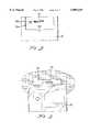
- FIG. 4is a side elevational view, partly in section, of a stand pivotally received in the receiving portion of the base;
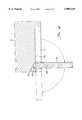
- FIG. 5is an illustrative view to show the stand can be hung on a bolt on a wall
- FIG. 6is a perspective view of the display tool box in which tools are received
- FIG. 7is a perspective view of the display tool box in accordance with the present invention, wherein a tool in the operation area is pivoted outwardly, and
- FIG. 8is an illustrative view to show the tool in the operation area is pivoted about a ratchet member and a stand is pivoted from the base.
- a display tool box in accordance with the present inventiongenerally includes a base 10 having a receiving area 101 with a plurality of recesses 11, 12 defined therein so as to receive tools, such as combination box and open end wrenches 30 (see FIG. 6) therein and a recessed operation area 13 having a hole 131 defined therethrough which has a toothed inner periphery 132 for a ratchet member 14 rotatably engaged therewith.
- the base 10has a stud 17 and a dent 18 respectively extending from and defined in each one of two ends thereof. Referring to FIGS.
- the base 10has a recessed portion 15 defined in an under side thereof and a slot 152 is defined in a bottom defining the recessed portion 15.
- Two sides defining the recessed portion 15each have a first recess 153 and a second recess 154 defined therein.
- the ratchet member 14has a polygonal head 143 and two curved portions 140 extending from the polygonal head 143 so that the two curved portions 140 can be pressed to approach with each other slightly.
- Each of the two curved portions 140has a toothed outer periphery 141 and a flange 142 extending from a lower edge thereof so that the two toothed outer peripheries 141 are engaged with the toothed inner periphery 132 of the hole 131 and the flanges 142 limit the ratchet member 14 from being disengaged from the toothed inner periphery 132.
- a flexible plate 19is connected to the base 10 and located next to the operation area 13, the flexible plate 19 has a second flange 191 extending upwardly therefrom and being flush with a side of the operation area 13.
- a transparent cover 20has two end skirts 201 extending downwardly from two opposite ends thereof and each end skirt 201 has an aperture 22 defined therethrough for receiving the corresponding stud 17 therein and a boss 23 extends from an inner side thereof so as to be received in the dent 18 corresponding thereto such that the transparent cover 20 can be pivoted about an axis connecting the two studs 17.
- a cut-away 21is defined in a side of the transparent cover 20 so that the operation area 13 can be accessed from the cut-away 21.
- a stand 16is pivotally disposed to the under side of the base 10 and is pivotally received in the recessed portion 15.
- the stand 16has a first positioning protrusion 164 and a second positioning protrusion 165 extending from each one of two ends thereof so that the first positioning protrusions 164 are pivotally received in the first recesses 153 and the second positioning protrusions 165 are received in the second recesses 154 when the stand 16 is pivoted to received in the recessed portion 15.
- the stand 16has a ridge 163 extending from one of two sides thereof so as to be pivotally received in the slot 152 when the stand 16 is pivoted perpendicular to the base 10 as shown FIG. 4.
- An inner end defining the recessed portion 15has a finger recess 151 defined therein as shown in FIG. 3 so that a user's finger can insert into the finger recess 151 to pull the stand 16 downwardly.
- the stand 16has a oblong hole 161 defined therethrough and a periphery defining the oblong hole 161 has a semi-circular recess 162 defined therein so that the stand 16 can be pivoted to a position parallel to the base 10 and be hung on a bolt on a wall as shown in FIG. 5.
- the combination box and open end wrenches 30are respectively received in the recesses 11, 12 in the receiving area 101 and one wrench 30' is received in the operation area 13 with its box end mounted to the polygonal head 143 of the ratchet member 14.
- the second flange 191limits the wrench 30' from dropping from the operation area 13.
- An open end of the wrench 30'can be pulled outwardly by pushing the flexible plate 19 downwardly slightly so that the user can hold the wrench 30' and rotates the wrench 30' about the ratchet member 14 to let the toothed outer peripheries 141 move across the toothed inner periphery 132 of the hole 131.
- the display tool box of the present inventionincludes the operation area 13 which provides a wrench 30' to be operated therein and this meets needs of the customers. Furthermore, the stand 16 is conveniently to let the display tool box be hung on the wall or stand on a table.
Landscapes
- Engineering & Computer Science (AREA)
- Mechanical Engineering (AREA)
- Packaging Of Annular Or Rod-Shaped Articles, Wearing Apparel, Cassettes, Or The Like (AREA)
- Display Racks (AREA)
- Details Of Rigid Or Semi-Rigid Containers (AREA)
Abstract
Description
1. Field of the Invention
The present invention relates to a display tool box and, more particularly, to an improved tool box having a receiving area and an operation area including a rotatable ratchet member and a tool, such as a spanner, rotatably engaged with the ratchet member so that a user may operate the tool in the operation area.
2. Brief Description of the Prior Art
A conventional display box generally is a plastic box for receiving a plurality of tools therein and having a transparent cover so that customers may see the tools via the transparent cover. However, such tools are not designed for simply having decorative purposes so that the conventional display tool boxes cannot meet needs of customers who want to operate the tools themselves. Furthermore, for manufacturers, the tools they produced once are put in the conventional display tool boxes will not able to show their special characters because customers cannot even touch them. Accordingly, the customers, the manufacturers and the dealers have the same need to have a new display tool box having a new style of displaying.
The present invention intends to provide an improved display tool box to mitigate and/or obviate the above-mentioned problems.
In one aspect of the present invention, there is provided a display tool box comprising a base having a receiving area with a plurality of recesses defined therein and an operation area having a hole defined therethrough which has a toothed inner periphery for a ratchet member rotatably engaged therewith.
It is an object of the present invention to provide a display tool box having an operation area to allow a customer to operate a tool in the operation area.
It is another object of the present invention to provide a display tool box having a stand which can be pivoted to be hung on a hook on a wall.
Other objects, advantages, and novel features of the invention will become more apparent from the following detailed description when taken in conjunction with the accompanying drawings.
FIG. 1 is a perspective view of a display tool box in accordance with the present invention;
FIG. 2 is an exploded view of the display tool box in accordance with the present invention;
FIG. 3 is a bottom view to show a receiving portion defined in an under side of the base;
FIG. 4 is a side elevational view, partly in section, of a stand pivotally received in the receiving portion of the base;
FIG. 5 is an illustrative view to show the stand can be hung on a bolt on a wall;
FIG. 6 is a perspective view of the display tool box in which tools are received;
FIG. 7 is a perspective view of the display tool box in accordance with the present invention, wherein a tool in the operation area is pivoted outwardly, and
FIG. 8 is an illustrative view to show the tool in the operation area is pivoted about a ratchet member and a stand is pivoted from the base.
Referring to the drawings and initially to FIGS. 1 through 3, a display tool box in accordance with the present invention generally includes abase 10 having areceiving area 101 with a plurality ofrecesses recessed operation area 13 having ahole 131 defined therethrough which has a toothedinner periphery 132 for aratchet member 14 rotatably engaged therewith. Thebase 10 has astud 17 and adent 18 respectively extending from and defined in each one of two ends thereof. Referring to FIGS. 3 and 4, thebase 10 has arecessed portion 15 defined in an under side thereof and aslot 152 is defined in a bottom defining therecessed portion 15. Two sides defining therecessed portion 15 each have afirst recess 153 and asecond recess 154 defined therein.
Theratchet member 14 has apolygonal head 143 and two curved portions 140 extending from thepolygonal head 143 so that the two curved portions 140 can be pressed to approach with each other slightly. Each of the two curved portions 140 has a toothedouter periphery 141 and a flange 142 extending from a lower edge thereof so that the two toothedouter peripheries 141 are engaged with the toothedinner periphery 132 of thehole 131 and the flanges 142 limit theratchet member 14 from being disengaged from the toothedinner periphery 132.
Aflexible plate 19 is connected to thebase 10 and located next to theoperation area 13, theflexible plate 19 has asecond flange 191 extending upwardly therefrom and being flush with a side of theoperation area 13.
Atransparent cover 20 has twoend skirts 201 extending downwardly from two opposite ends thereof and eachend skirt 201 has anaperture 22 defined therethrough for receiving thecorresponding stud 17 therein and aboss 23 extends from an inner side thereof so as to be received in thedent 18 corresponding thereto such that thetransparent cover 20 can be pivoted about an axis connecting the twostuds 17. A cut-away 21 is defined in a side of thetransparent cover 20 so that theoperation area 13 can be accessed from the cut-away 21.
Astand 16 is pivotally disposed to the under side of thebase 10 and is pivotally received in the recessedportion 15. Thestand 16 has afirst positioning protrusion 164 and asecond positioning protrusion 165 extending from each one of two ends thereof so that thefirst positioning protrusions 164 are pivotally received in thefirst recesses 153 and thesecond positioning protrusions 165 are received in thesecond recesses 154 when thestand 16 is pivoted to received in therecessed portion 15. Thestand 16 has aridge 163 extending from one of two sides thereof so as to be pivotally received in theslot 152 when thestand 16 is pivoted perpendicular to thebase 10 as shown FIG. 4. An inner end defining therecessed portion 15 has afinger recess 151 defined therein as shown in FIG. 3 so that a user's finger can insert into thefinger recess 151 to pull thestand 16 downwardly. Thestand 16 has aoblong hole 161 defined therethrough and a periphery defining theoblong hole 161 has asemi-circular recess 162 defined therein so that thestand 16 can be pivoted to a position parallel to thebase 10 and be hung on a bolt on a wall as shown in FIG. 5.
Referring now to FIGS. 6 through 8, the combination box andopen end wrenches 30 are respectively received in therecesses receiving area 101 and one wrench 30' is received in theoperation area 13 with its box end mounted to thepolygonal head 143 of theratchet member 14. Thesecond flange 191 limits the wrench 30' from dropping from theoperation area 13. An open end of the wrench 30' can be pulled outwardly by pushing theflexible plate 19 downwardly slightly so that the user can hold the wrench 30' and rotates the wrench 30' about theratchet member 14 to let the toothedouter peripheries 141 move across the toothedinner periphery 132 of thehole 131.
Accordingly, the display tool box of the present invention includes theoperation area 13 which provides a wrench 30' to be operated therein and this meets needs of the customers. Furthermore, thestand 16 is conveniently to let the display tool box be hung on the wall or stand on a table.
Although the invention has been explained in relation to its preferred embodiment, it is to be understood that many other possible modifications and variations can be made without departing from the spirit and scope of the invention as hereinafter claimed.
Claims (4)
1. A display tool box comprising:
a base having a receiving area with a plurality of recesses defined therein and an operation area having a hole defined therethrough which has a toothed inner periphery, and a ratchet member rotatably engaged in said toothed inner periphery;
a flexible plate connected to said base and located next to said operation area, said flexible plate having a first flange and a second flange extending upwardly therefrom and being flush with a side of said operation area.
2. The display tool box as claimed in claim 1 wherein said base has a stud and a dent respectively formed on each one of two ends thereof, a transparent cover having two end skirts extending downwardly from two opposite ends thereof and each end skirt having an aperture defined therethrough for receiving said corresponding stud therein and a boss extending from an inner side thereof so as to be received in said dent corresponding thereto.
3. The display tool box as claimed in claim 1 wherein a stand is pivotally disposed to an under side of said base.
4. A display tool box comprising:
a base having a receiving area with a plurality of recesses defined therein and an operation area having a hole defined therethrough which has a toothed inner periphery;
a ratchet member rotatably engaged in said toothed inner periphery wherein a stand is pivotally disposed to an under side of the base and wherein said under side of said base has a recessed portion defined therein and a slot is defined in a bottom defining said recessed portion, two sides defining said recessed portion each having a first recess and a second recess defined therein, said stand having a ridge extending from one of two sides thereof so as to be pivotally received in said slot when said stand is pivoted perpendicular to said base, said stand having a first positioning protrusion and a second positioning protrusion extending from each one of two ends thereof so that said first positioning protrusions are pivotally received in said first recesses and said second positioning protrusions are received in said second recesses when said stand is pivoted to be received in said recessed portion.
Priority Applications (3)
| Application Number | Priority Date | Filing Date | Title |
|---|---|---|---|
| GB9722144AGB2330571B (en) | 1997-10-21 | 1997-10-21 | Display tool box |
| US08/957,969US5899329A (en) | 1997-10-21 | 1997-10-21 | Display tool box |
| DE19747374ADE19747374C2 (en) | 1997-10-21 | 1997-10-27 | Tool containers for display purposes |
Applications Claiming Priority (3)
| Application Number | Priority Date | Filing Date | Title |
|---|---|---|---|
| GB9722144AGB2330571B (en) | 1997-10-21 | 1997-10-21 | Display tool box |
| US08/957,969US5899329A (en) | 1997-10-21 | 1997-10-21 | Display tool box |
| DE19747374ADE19747374C2 (en) | 1997-10-21 | 1997-10-27 | Tool containers for display purposes |
Publications (1)
| Publication Number | Publication Date |
|---|---|
| US5899329Atrue US5899329A (en) | 1999-05-04 |
Family
ID=27217863
Family Applications (1)
| Application Number | Title | Priority Date | Filing Date |
|---|---|---|---|
| US08/957,969Expired - Fee RelatedUS5899329A (en) | 1997-10-21 | 1997-10-21 | Display tool box |
Country Status (3)
| Country | Link |
|---|---|
| US (1) | US5899329A (en) |
| DE (1) | DE19747374C2 (en) |
| GB (1) | GB2330571B (en) |
Cited By (50)
| Publication number | Priority date | Publication date | Assignee | Title |
|---|---|---|---|---|
| US6059108A (en)* | 1998-10-30 | 2000-05-09 | Schiltz, Jr.; Richard | Wrench organizer for a toolbox |
| USD427435S (en)* | 1999-08-06 | 2000-07-04 | Lf Corporation | Carrying and storage case |
| US6126004A (en)* | 1999-07-01 | 2000-10-03 | Hand Tool Design Corporation | Tool display box |
| USD446935S1 (en) | 2000-05-30 | 2001-08-28 | Wen-Kuo Huang | Tool box |
| USD483180S1 (en) | 2002-09-11 | 2003-12-09 | Terence Chen | Tool box |
| US20040094444A1 (en)* | 2002-11-18 | 2004-05-20 | Terence Chen | Hanger for wrenches |
| US20040256336A1 (en)* | 2001-07-16 | 2004-12-23 | David Ling | Tool rack assembly |
| US6857527B2 (en) | 2000-11-24 | 2005-02-22 | Bobby Hu | Tool rack with anti-theft, display, and try-on functions |
| US20050218092A1 (en)* | 2004-04-02 | 2005-10-06 | Rosen Ian K | Angulated package and display system |
| US20060175217A1 (en)* | 2005-02-05 | 2006-08-10 | Bobby Hu | Portable toolbox |
| DE10333286B4 (en)* | 2002-07-23 | 2006-09-07 | Chen, Terence, Tung Shan | Toolbox with a ratchet tool tester |
| US7350645B1 (en) | 2005-02-24 | 2008-04-01 | Stephen Sills | Product security system for hanging merchandise |
| US20080083634A1 (en)* | 2006-10-05 | 2008-04-10 | Harold Parker | Method and device for holding objects |
| US20080093431A1 (en)* | 2004-04-02 | 2008-04-24 | Ags I-Prop, Llc | Angled package and display system |
| US7631877B2 (en) | 2006-01-26 | 2009-12-15 | Battenfeld Technologies, Inc. | Firearm targets and methods for manufacturing firearm targets |
| US7681886B2 (en) | 2006-02-24 | 2010-03-23 | Battenfeld Technologies, Inc. | Shooting gallery devices and methods |
| US7726478B2 (en) | 2006-02-27 | 2010-06-01 | Battenfeld Technologies, Inc. | Containers for carrying firearm accessories and/or supporting firearms |
| US20100136875A1 (en)* | 2008-10-15 | 2010-06-03 | Mattel, Inc. | Packaged Toy With Selector |
| USD617556S1 (en) | 2009-11-12 | 2010-06-15 | IBT Holdings, Inc. | Stubby tool case |
| USD617557S1 (en) | 2009-07-02 | 2010-06-15 | IBT Holdings, Inc. | Tool case |
| US20100200443A1 (en)* | 2009-02-09 | 2010-08-12 | Jeffrey Allen Greene | Package for Holding and Displaying Shaving Razors |
| US7774972B2 (en) | 2006-09-11 | 2010-08-17 | Battenfeld Technologies, Inc. | Modular shooting rests and shooting rest assemblies |
| US7779572B2 (en) | 2006-05-08 | 2010-08-24 | Battenfeld Technologies, Inc. | Bipod device for use with a firearm |
| US20100243496A1 (en)* | 2009-03-27 | 2010-09-30 | Infar Industrial Co., Ltd. | Tool box |
| US7823317B2 (en) | 2006-08-22 | 2010-11-02 | Battenfeld Technologies, Inc. | Adjustable shooting rests and shooting rest assemblies |
| US7845267B2 (en) | 2007-09-11 | 2010-12-07 | Battenfield Technologies, Inc. | Attachment mechanisms for coupling firearms to supporting structures |
| US7946071B2 (en) | 2004-11-10 | 2011-05-24 | Battenfeld Technologies, Inc. | Firearm vise |
| US7954272B2 (en) | 2007-05-08 | 2011-06-07 | Battenfeld Technologies, Inc. | Adjustable firearm supports and associated methods of use and manufacture |
| US7997021B2 (en) | 2008-11-21 | 2011-08-16 | Battenfeld Technologies | Shooting rests with adjustable height assemblies |
| US8011129B2 (en) | 2003-06-13 | 2011-09-06 | Battenfeld Technologies, Inc. | Recoil-reducing shooting rest |
| USD644901S1 (en) | 2010-03-17 | 2011-09-13 | Meridian International Co., Ltd. | Hand tool |
| US20110226648A1 (en)* | 2010-03-19 | 2011-09-22 | Meridian International Co., Ltd. | case for holding a hand tool |
| USD645733S1 (en) | 2011-02-03 | 2011-09-27 | Meridian International Co., Ltd. | Hand tool packaging |
| US8079469B2 (en) | 2009-07-07 | 2011-12-20 | Meridian International Co., Ltd. | Case for holding a hand tool |
| US8104212B2 (en) | 2006-02-24 | 2012-01-31 | Battenfeld Technologies, Inc. | Firearm supports, such as shooting bags, and firearm support assemblies |
| US8296988B2 (en) | 2006-11-30 | 2012-10-30 | Battenfeld Technologies, Inc. | Firearm supporting devices, methods of assembling firearm supporting devices, and methods of packaging firearm supporting devices |
| US8336708B2 (en) | 2007-07-20 | 2012-12-25 | Battenfeld Technologies, Inc. | System and container for organizing and carrying tools and tool sets |
| US8371057B2 (en) | 2006-05-09 | 2013-02-12 | Battenfeld Technologies, Inc. | Firearm cleaning apparatus with protective coating |
| US20130043201A1 (en)* | 2011-08-16 | 2013-02-21 | Tzu-Chien Wang | Hand tool display box |
| US20130299367A1 (en)* | 2012-05-09 | 2013-11-14 | Office Depot, Inc. | Packaging for writing instruments |
| US8621773B2 (en) | 2003-06-13 | 2014-01-07 | Battenfeld Technologies, Inc. | Shooting rests for supporting firearms |
| US8695985B2 (en) | 2011-01-07 | 2014-04-15 | Battenfeld Technologies, Inc. | Stowable shooting target assemblies |
| US8931201B2 (en) | 2012-12-31 | 2015-01-13 | Battenfeld Technologies, Inc. | Gun support apparatus |
| USD758813S1 (en) | 2015-05-20 | 2016-06-14 | Meridian International Co., Ltd. | T-handle |
| US9702653B2 (en) | 2015-10-09 | 2017-07-11 | Battenfeld Technologies, Inc. | Firearm shooting rest |
| US10435219B2 (en) | 2017-08-24 | 2019-10-08 | Meridian International Co., Ltd. | Display package for a hand tool |
| US10514225B2 (en) | 2018-01-17 | 2019-12-24 | Battenfeld Technologies, Inc. | Firearm shooting rest |
| US10782085B2 (en) | 2019-02-15 | 2020-09-22 | Aob Products Company | Recoil-reducing firearm shooting rest having tank |
| US11841108B2 (en) | 2019-12-17 | 2023-12-12 | Aob Products Company | Multi-legged equipment support having leg angle adjustment |
| US12004658B2 (en) | 2021-04-15 | 2024-06-11 | Aob Products Company | Shooting rest chair |
Citations (9)
| Publication number | Priority date | Publication date | Assignee | Title |
|---|---|---|---|---|
| US880590A (en)* | 1907-08-17 | 1908-03-03 | Adolph Sommer | Display-box. |
| US5203469A (en)* | 1992-06-01 | 1993-04-20 | Roger Chang | Tool box |
| US5205474A (en)* | 1992-06-02 | 1993-04-27 | Oscar Mayer Foods Corporation | Easy set-up carton and method |
| US5372273A (en)* | 1994-01-21 | 1994-12-13 | Eves; Mark G. | Inclinable compartmented storage container |
| US5509528A (en)* | 1994-11-16 | 1996-04-23 | Alpha Enterprises, Inc. | Display package |
| US5570784A (en)* | 1992-12-24 | 1996-11-05 | Allied Wholesale, Inc. | Tool organizer and deployment apparatus |
| US5598924A (en)* | 1995-10-06 | 1997-02-04 | Chiro Tool Mfg Corp. | Spanner holder |
| US5730303A (en)* | 1996-09-13 | 1998-03-24 | Hand Tool Design Corporation | Hand tool rack |
| US5785174A (en)* | 1997-06-09 | 1998-07-28 | Hand Tool Design Corporation | Display pack having a rotatable security member |
Family Cites Families (4)
| Publication number | Priority date | Publication date | Assignee | Title |
|---|---|---|---|---|
| US3726393A (en)* | 1970-12-08 | 1973-04-10 | D Thompson | Socket wrench retainer and assemblies |
| DE2851044A1 (en)* | 1978-11-25 | 1980-06-04 | Mesenhoeller Hans Kg | Tool assortment box with fixed panel for basic tools - has interchangeable panels with different selections of add-on tool components |
| US5344012A (en)* | 1993-09-07 | 1994-09-06 | Matthews James R | Socket caddy |
| DE29701192U1 (en)* | 1997-01-24 | 1997-03-27 | Huang, Wen-Kuo, Tainan | Toolbox |
- 1997
- 1997-10-21USUS08/957,969patent/US5899329A/ennot_activeExpired - Fee Related
- 1997-10-21GBGB9722144Apatent/GB2330571B/ennot_activeExpired - Fee Related
- 1997-10-27DEDE19747374Apatent/DE19747374C2/ennot_activeExpired - Fee Related
Patent Citations (9)
| Publication number | Priority date | Publication date | Assignee | Title |
|---|---|---|---|---|
| US880590A (en)* | 1907-08-17 | 1908-03-03 | Adolph Sommer | Display-box. |
| US5203469A (en)* | 1992-06-01 | 1993-04-20 | Roger Chang | Tool box |
| US5205474A (en)* | 1992-06-02 | 1993-04-27 | Oscar Mayer Foods Corporation | Easy set-up carton and method |
| US5570784A (en)* | 1992-12-24 | 1996-11-05 | Allied Wholesale, Inc. | Tool organizer and deployment apparatus |
| US5372273A (en)* | 1994-01-21 | 1994-12-13 | Eves; Mark G. | Inclinable compartmented storage container |
| US5509528A (en)* | 1994-11-16 | 1996-04-23 | Alpha Enterprises, Inc. | Display package |
| US5598924A (en)* | 1995-10-06 | 1997-02-04 | Chiro Tool Mfg Corp. | Spanner holder |
| US5730303A (en)* | 1996-09-13 | 1998-03-24 | Hand Tool Design Corporation | Hand tool rack |
| US5785174A (en)* | 1997-06-09 | 1998-07-28 | Hand Tool Design Corporation | Display pack having a rotatable security member |
Cited By (88)
| Publication number | Priority date | Publication date | Assignee | Title |
|---|---|---|---|---|
| US6059108A (en)* | 1998-10-30 | 2000-05-09 | Schiltz, Jr.; Richard | Wrench organizer for a toolbox |
| US6126004A (en)* | 1999-07-01 | 2000-10-03 | Hand Tool Design Corporation | Tool display box |
| USD427435S (en)* | 1999-08-06 | 2000-07-04 | Lf Corporation | Carrying and storage case |
| USD446935S1 (en) | 2000-05-30 | 2001-08-28 | Wen-Kuo Huang | Tool box |
| US6857527B2 (en) | 2000-11-24 | 2005-02-22 | Bobby Hu | Tool rack with anti-theft, display, and try-on functions |
| US7175032B2 (en) | 2001-07-16 | 2007-02-13 | Easco Hand Tools, Inc. | Tool rack assembly |
| US20050274683A1 (en)* | 2001-07-16 | 2005-12-15 | Hand Tool Design Corporation | Tool rack assembly |
| US20040256336A1 (en)* | 2001-07-16 | 2004-12-23 | David Ling | Tool rack assembly |
| DE10333286B4 (en)* | 2002-07-23 | 2006-09-07 | Chen, Terence, Tung Shan | Toolbox with a ratchet tool tester |
| USD483180S1 (en) | 2002-09-11 | 2003-12-09 | Terence Chen | Tool box |
| US20040094444A1 (en)* | 2002-11-18 | 2004-05-20 | Terence Chen | Hanger for wrenches |
| US7055689B2 (en) | 2002-11-18 | 2006-06-06 | Terence Chen | Hanger for wrenches |
| US10859336B2 (en) | 2003-06-13 | 2020-12-08 | Aob Products Company | Shooting rests for supporting firearms |
| US10317162B2 (en) | 2003-06-13 | 2019-06-11 | Battenfeld Technologies, Inc. | Shooting rests for supporting firearms |
| US8011129B2 (en) | 2003-06-13 | 2011-09-06 | Battenfeld Technologies, Inc. | Recoil-reducing shooting rest |
| US8621773B2 (en) | 2003-06-13 | 2014-01-07 | Battenfeld Technologies, Inc. | Shooting rests for supporting firearms |
| US9151561B2 (en) | 2003-06-13 | 2015-10-06 | Battenfeld Technologies, Inc. | Shooting rests for supporting firearms |
| US7520394B2 (en) | 2004-04-02 | 2009-04-21 | American Grease Stick Company | Angulated package and display system |
| US20070163970A1 (en)* | 2004-04-02 | 2007-07-19 | American Grease Stick Company | Angulated package and display system |
| US20080093431A1 (en)* | 2004-04-02 | 2008-04-24 | Ags I-Prop, Llc | Angled package and display system |
| US20110120963A1 (en)* | 2004-04-02 | 2011-05-26 | Ags I-Prop, Llc | Angled package and display system |
| US20060237380A1 (en)* | 2004-04-02 | 2006-10-26 | Rosen Ian K | Angulated wall hanging device |
| US20050218092A1 (en)* | 2004-04-02 | 2005-10-06 | Rosen Ian K | Angulated package and display system |
| US7918352B2 (en) | 2004-04-02 | 2011-04-05 | Ags I-Prop, Llc | Angled package and display system |
| US8069992B2 (en) | 2004-04-02 | 2011-12-06 | Ags I-Prop, Llc | Angled package and display system |
| US7204373B2 (en) | 2004-04-02 | 2007-04-17 | American Grease Stick Company | Angulated package and display system |
| US8578645B2 (en) | 2004-11-10 | 2013-11-12 | Battenfeld Technologies, Inc. | Firearm vise |
| US7946071B2 (en) | 2004-11-10 | 2011-05-24 | Battenfeld Technologies, Inc. | Firearm vise |
| US20060175217A1 (en)* | 2005-02-05 | 2006-08-10 | Bobby Hu | Portable toolbox |
| US7434688B2 (en) | 2005-02-05 | 2008-10-14 | Bobby Hu | Portable toolbox |
| US7350645B1 (en) | 2005-02-24 | 2008-04-01 | Stephen Sills | Product security system for hanging merchandise |
| US7631877B2 (en) | 2006-01-26 | 2009-12-15 | Battenfeld Technologies, Inc. | Firearm targets and methods for manufacturing firearm targets |
| US7681886B2 (en) | 2006-02-24 | 2010-03-23 | Battenfeld Technologies, Inc. | Shooting gallery devices and methods |
| US8104212B2 (en) | 2006-02-24 | 2012-01-31 | Battenfeld Technologies, Inc. | Firearm supports, such as shooting bags, and firearm support assemblies |
| US7726478B2 (en) | 2006-02-27 | 2010-06-01 | Battenfeld Technologies, Inc. | Containers for carrying firearm accessories and/or supporting firearms |
| US7779572B2 (en) | 2006-05-08 | 2010-08-24 | Battenfeld Technologies, Inc. | Bipod device for use with a firearm |
| US8316570B2 (en) | 2006-05-08 | 2012-11-27 | Battenfeld Technologies, Inc. | Bipod device for use with a firearm |
| US8371057B2 (en) | 2006-05-09 | 2013-02-12 | Battenfeld Technologies, Inc. | Firearm cleaning apparatus with protective coating |
| US7823317B2 (en) | 2006-08-22 | 2010-11-02 | Battenfeld Technologies, Inc. | Adjustable shooting rests and shooting rest assemblies |
| US8132351B2 (en) | 2006-08-22 | 2012-03-13 | Battenfeld Technologies, Inc. | Adjustable shooting rests and shooting rest assemblies |
| US8356442B2 (en) | 2006-08-22 | 2013-01-22 | Battenfeld Technologies, Inc. | Adjustable shooting rests and shooting rest assemblies |
| US7774972B2 (en) | 2006-09-11 | 2010-08-17 | Battenfeld Technologies, Inc. | Modular shooting rests and shooting rest assemblies |
| US20080083634A1 (en)* | 2006-10-05 | 2008-04-10 | Harold Parker | Method and device for holding objects |
| US8296988B2 (en) | 2006-11-30 | 2012-10-30 | Battenfeld Technologies, Inc. | Firearm supporting devices, methods of assembling firearm supporting devices, and methods of packaging firearm supporting devices |
| US7954272B2 (en) | 2007-05-08 | 2011-06-07 | Battenfeld Technologies, Inc. | Adjustable firearm supports and associated methods of use and manufacture |
| US8336708B2 (en) | 2007-07-20 | 2012-12-25 | Battenfeld Technologies, Inc. | System and container for organizing and carrying tools and tool sets |
| US7845267B2 (en) | 2007-09-11 | 2010-12-07 | Battenfield Technologies, Inc. | Attachment mechanisms for coupling firearms to supporting structures |
| US8464628B2 (en) | 2007-09-11 | 2013-06-18 | Battenfeld Technologies, Inc. | Attachment mechanisms for coupling firearms to supporting structures |
| US8408393B2 (en)* | 2008-10-15 | 2013-04-02 | Mattel, Inc. | Packaged toy with selector |
| US20100136875A1 (en)* | 2008-10-15 | 2010-06-03 | Mattel, Inc. | Packaged Toy With Selector |
| US8393106B2 (en) | 2008-11-21 | 2013-03-12 | Battenfeld Technologies, Inc. | Shooting rests with adjustable height for supporting firearms |
| US7997021B2 (en) | 2008-11-21 | 2011-08-16 | Battenfeld Technologies | Shooting rests with adjustable height assemblies |
| US20100294684A1 (en)* | 2009-02-09 | 2010-11-25 | Jeffrey Allen Greene | Package for holding and displaying shaving razors |
| US7854320B2 (en)* | 2009-02-09 | 2010-12-21 | The Gillette Company | Package for holding and displaying shaving razors |
| US20100200443A1 (en)* | 2009-02-09 | 2010-08-12 | Jeffrey Allen Greene | Package for Holding and Displaying Shaving Razors |
| US8522972B2 (en) | 2009-02-09 | 2013-09-03 | The Gillette Company | Package for holding and displaying shaving razors |
| US7854318B2 (en)* | 2009-03-27 | 2010-12-21 | Infar Industrial Co., Ltd. | Tool box |
| US20100243496A1 (en)* | 2009-03-27 | 2010-09-30 | Infar Industrial Co., Ltd. | Tool box |
| USD617557S1 (en) | 2009-07-02 | 2010-06-15 | IBT Holdings, Inc. | Tool case |
| US20120043239A1 (en)* | 2009-07-07 | 2012-02-23 | Meridian International Co., Ltd. | Case for holding a hand tool |
| US8079469B2 (en) | 2009-07-07 | 2011-12-20 | Meridian International Co., Ltd. | Case for holding a hand tool |
| US8517173B2 (en)* | 2009-07-07 | 2013-08-27 | Meridian International Co., Ltd. | Case for holding a hand tool |
| USD617556S1 (en) | 2009-11-12 | 2010-06-15 | IBT Holdings, Inc. | Stubby tool case |
| USD672957S1 (en) | 2010-03-17 | 2012-12-25 | Meridian International Co., Ltd. | Storage case for a hand tool |
| USD644901S1 (en) | 2010-03-17 | 2011-09-13 | Meridian International Co., Ltd. | Hand tool |
| US20110226098A1 (en)* | 2010-03-19 | 2011-09-22 | Meridian International Co., Ltd. | Ergonomic handle with storage chamber and driver incorporating the same |
| US20110226648A1 (en)* | 2010-03-19 | 2011-09-22 | Meridian International Co., Ltd. | case for holding a hand tool |
| US8157092B2 (en)* | 2010-03-19 | 2012-04-17 | Meridian International Co., Ltd. | Case for holding a hand tool |
| US8695985B2 (en) | 2011-01-07 | 2014-04-15 | Battenfeld Technologies, Inc. | Stowable shooting target assemblies |
| USD645733S1 (en) | 2011-02-03 | 2011-09-27 | Meridian International Co., Ltd. | Hand tool packaging |
| US20130043201A1 (en)* | 2011-08-16 | 2013-02-21 | Tzu-Chien Wang | Hand tool display box |
| US8839950B2 (en)* | 2012-05-09 | 2014-09-23 | Office Depot, Inc. | Packaging for writing instruments |
| US20130299367A1 (en)* | 2012-05-09 | 2013-11-14 | Office Depot, Inc. | Packaging for writing instruments |
| US8931201B2 (en) | 2012-12-31 | 2015-01-13 | Battenfeld Technologies, Inc. | Gun support apparatus |
| USD758813S1 (en) | 2015-05-20 | 2016-06-14 | Meridian International Co., Ltd. | T-handle |
| US9702653B2 (en) | 2015-10-09 | 2017-07-11 | Battenfeld Technologies, Inc. | Firearm shooting rest |
| US10435219B2 (en) | 2017-08-24 | 2019-10-08 | Meridian International Co., Ltd. | Display package for a hand tool |
| US10926931B2 (en) | 2017-08-24 | 2021-02-23 | Meridian International Co., Ltd. | Display package for a hand tool |
| US10514225B2 (en) | 2018-01-17 | 2019-12-24 | Battenfeld Technologies, Inc. | Firearm shooting rest |
| US11009306B2 (en) | 2018-01-17 | 2021-05-18 | Aob Products Company | Firearm shooting rest |
| US10782085B2 (en) | 2019-02-15 | 2020-09-22 | Aob Products Company | Recoil-reducing firearm shooting rest having tank |
| US11333461B2 (en) | 2019-02-15 | 2022-05-17 | Aob Products Company | Recoil-reducing firearm shooting rest having tank |
| US11796274B2 (en) | 2019-02-15 | 2023-10-24 | Aob Products Company | Recoil-reducing firearm shooting rest having tank |
| US12228361B2 (en) | 2019-02-15 | 2025-02-18 | Aob Products Company | Recoil-reducing firearm shooting rest having tank |
| US11841108B2 (en) | 2019-12-17 | 2023-12-12 | Aob Products Company | Multi-legged equipment support having leg angle adjustment |
| US12146608B2 (en) | 2019-12-17 | 2024-11-19 | Aob Products Company | Multi-legged equipment support having leg angle adjustment |
| US12004658B2 (en) | 2021-04-15 | 2024-06-11 | Aob Products Company | Shooting rest chair |
| US12408757B2 (en) | 2021-04-15 | 2025-09-09 | Aob Products Company | Shooting rest chair |
Also Published As
| Publication number | Publication date |
|---|---|
| DE19747374A1 (en) | 1999-04-29 |
| GB2330571A (en) | 1999-04-28 |
| DE19747374C2 (en) | 1999-12-02 |
| GB2330571B (en) | 1999-09-08 |
| GB9722144D0 (en) | 1997-12-17 |
Similar Documents
| Publication | Publication Date | Title |
|---|---|---|
| US5899329A (en) | Display tool box | |
| US4930628A (en) | Storage and display case having pivotally mounted cover | |
| US5918741A (en) | Tool case | |
| JP2789389B2 (en) | Tool display package | |
| US5803254A (en) | Tool case with multiple storage compartments | |
| US6131740A (en) | Toolbox | |
| US7228983B2 (en) | Storage container | |
| US5785174A (en) | Display pack having a rotatable security member | |
| US5816401A (en) | Hex key holder | |
| US4431114A (en) | Container and removable cover | |
| US6126004A (en) | Tool display box | |
| US20080128370A1 (en) | Socket Holder | |
| US5788072A (en) | Tool box | |
| JPH07120201A (en) | Tape measure package | |
| US7175032B2 (en) | Tool rack assembly | |
| US7195120B2 (en) | Tool bit storage and display container | |
| US7306099B2 (en) | Toolbox | |
| US20040031807A1 (en) | Box and cover combination | |
| US7175151B2 (en) | Hand tool suspension device | |
| US20030085141A1 (en) | Compartmentalized tool box | |
| US7623024B2 (en) | Adjustable door chime with interchangeable parts | |
| US20020162763A1 (en) | Display pack having rotatable security member | |
| US20040163971A1 (en) | Modular container | |
| USRE37129E1 (en) | Display pack having a rotatable security member | |
| CN103659776B (en) | The card structure of the tool box |
Legal Events
| Date | Code | Title | Description |
|---|---|---|---|
| AS | Assignment | Owner name:HAND TOOL DESIGN CORPORATION, DELAWARE Free format text:ASSIGNMENT OF ASSIGNORS INTEREST;ASSIGNORS:HU, BOBBY;LING, DAVID;REEL/FRAME:008874/0971 Effective date:19971014 | |
| FPAY | Fee payment | Year of fee payment:4 | |
| AS | Assignment | Owner name:EASCO HAND TOOLS, INC., CONNECTICUT Free format text:ASSIGNMENT OF ASSIGNORS INTEREST;ASSIGNOR:HAND TOOL DESIGN CORPORATION;REEL/FRAME:015312/0851 Effective date:20040405 | |
| FEPP | Fee payment procedure | Free format text:PAYOR NUMBER ASSIGNED (ORIGINAL EVENT CODE: ASPN); ENTITY STATUS OF PATENT OWNER: LARGE ENTITY | |
| FPAY | Fee payment | Year of fee payment:8 | |
| REMI | Maintenance fee reminder mailed | ||
| LAPS | Lapse for failure to pay maintenance fees | ||
| STCH | Information on status: patent discontinuation | Free format text:PATENT EXPIRED DUE TO NONPAYMENT OF MAINTENANCE FEES UNDER 37 CFR 1.362 | |
| FP | Lapsed due to failure to pay maintenance fee | Effective date:20110504 |