US5898585A - Apparatus and method for providing supplemental alternating current from a solar cell array - Google Patents
Apparatus and method for providing supplemental alternating current from a solar cell arrayDownload PDFInfo
- Publication number
- US5898585A US5898585AUS08/865,228US86522897AUS5898585AUS 5898585 AUS5898585 AUS 5898585AUS 86522897 AUS86522897 AUS 86522897AUS 5898585 AUS5898585 AUS 5898585A
- Authority
- US
- United States
- Prior art keywords
- circuit
- recited
- power
- switching devices
- voltage signal
- Prior art date
- Legal status (The legal status is an assumption and is not a legal conclusion. Google has not performed a legal analysis and makes no representation as to the accuracy of the status listed.)
- Expired - Fee Related
Links
Images


Classifications
- H—ELECTRICITY
- H02—GENERATION; CONVERSION OR DISTRIBUTION OF ELECTRIC POWER
- H02J—CIRCUIT ARRANGEMENTS OR SYSTEMS FOR SUPPLYING OR DISTRIBUTING ELECTRIC POWER; SYSTEMS FOR STORING ELECTRIC ENERGY
- H02J7/00—Circuit arrangements for charging or depolarising batteries or for supplying loads from batteries
- H02J7/34—Parallel operation in networks using both storage and other DC sources, e.g. providing buffering
- H02J7/35—Parallel operation in networks using both storage and other DC sources, e.g. providing buffering with light sensitive cells
- H—ELECTRICITY
- H02—GENERATION; CONVERSION OR DISTRIBUTION OF ELECTRIC POWER
- H02J—CIRCUIT ARRANGEMENTS OR SYSTEMS FOR SUPPLYING OR DISTRIBUTING ELECTRIC POWER; SYSTEMS FOR STORING ELECTRIC ENERGY
- H02J3/00—Circuit arrangements for AC mains or AC distribution networks
- H02J3/38—Arrangements for parallely feeding a single network by two or more generators, converters or transformers
- H02J3/381—Dispersed generators
- H—ELECTRICITY
- H02—GENERATION; CONVERSION OR DISTRIBUTION OF ELECTRIC POWER
- H02J—CIRCUIT ARRANGEMENTS OR SYSTEMS FOR SUPPLYING OR DISTRIBUTING ELECTRIC POWER; SYSTEMS FOR STORING ELECTRIC ENERGY
- H02J3/00—Circuit arrangements for AC mains or AC distribution networks
- H02J3/38—Arrangements for parallely feeding a single network by two or more generators, converters or transformers
- H02J3/40—Synchronising a generator for connection to a network or to another generator
- H02J3/44—Synchronising a generator for connection to a network or to another generator with means for ensuring correct phase sequence
- H—ELECTRICITY
- H02—GENERATION; CONVERSION OR DISTRIBUTION OF ELECTRIC POWER
- H02J—CIRCUIT ARRANGEMENTS OR SYSTEMS FOR SUPPLYING OR DISTRIBUTING ELECTRIC POWER; SYSTEMS FOR STORING ELECTRIC ENERGY
- H02J2300/00—Systems for supplying or distributing electric power characterised by decentralized, dispersed, or local generation
- H02J2300/20—The dispersed energy generation being of renewable origin
- H02J2300/22—The renewable source being solar energy
- H02J2300/24—The renewable source being solar energy of photovoltaic origin
- Y—GENERAL TAGGING OF NEW TECHNOLOGICAL DEVELOPMENTS; GENERAL TAGGING OF CROSS-SECTIONAL TECHNOLOGIES SPANNING OVER SEVERAL SECTIONS OF THE IPC; TECHNICAL SUBJECTS COVERED BY FORMER USPC CROSS-REFERENCE ART COLLECTIONS [XRACs] AND DIGESTS
- Y02—TECHNOLOGIES OR APPLICATIONS FOR MITIGATION OR ADAPTATION AGAINST CLIMATE CHANGE
- Y02A—TECHNOLOGIES FOR ADAPTATION TO CLIMATE CHANGE
- Y02A30/00—Adapting or protecting infrastructure or their operation
- Y02A30/60—Planning or developing urban green infrastructure
- Y—GENERAL TAGGING OF NEW TECHNOLOGICAL DEVELOPMENTS; GENERAL TAGGING OF CROSS-SECTIONAL TECHNOLOGIES SPANNING OVER SEVERAL SECTIONS OF THE IPC; TECHNICAL SUBJECTS COVERED BY FORMER USPC CROSS-REFERENCE ART COLLECTIONS [XRACs] AND DIGESTS
- Y02—TECHNOLOGIES OR APPLICATIONS FOR MITIGATION OR ADAPTATION AGAINST CLIMATE CHANGE
- Y02B—CLIMATE CHANGE MITIGATION TECHNOLOGIES RELATED TO BUILDINGS, e.g. HOUSING, HOUSE APPLIANCES OR RELATED END-USER APPLICATIONS
- Y02B10/00—Integration of renewable energy sources in buildings
- Y02B10/10—Photovoltaic [PV]
- Y—GENERAL TAGGING OF NEW TECHNOLOGICAL DEVELOPMENTS; GENERAL TAGGING OF CROSS-SECTIONAL TECHNOLOGIES SPANNING OVER SEVERAL SECTIONS OF THE IPC; TECHNICAL SUBJECTS COVERED BY FORMER USPC CROSS-REFERENCE ART COLLECTIONS [XRACs] AND DIGESTS
- Y02—TECHNOLOGIES OR APPLICATIONS FOR MITIGATION OR ADAPTATION AGAINST CLIMATE CHANGE
- Y02E—REDUCTION OF GREENHOUSE GAS [GHG] EMISSIONS, RELATED TO ENERGY GENERATION, TRANSMISSION OR DISTRIBUTION
- Y02E10/00—Energy generation through renewable energy sources
- Y02E10/50—Photovoltaic [PV] energy
- Y02E10/56—Power conversion systems, e.g. maximum power point trackers
Definitions
- the present inventionrelates in general to power converters and more particularly, to a solar inverter circuit that: (i) converts direct current (DC) power from a solar photovoltaic array to a counterflowing alternating current (AC) power in response to a reference AC power source, and (ii) generates additional AC power to supplement the reference AC power source.
- DCdirect current
- ACalternating current
- Conversion of direct current (DC) power from solar cells to alternating current (AC) power required in residential AC linesusually employs a large number of batteries for storing DC electrical energy from solar cells during day-time.
- the batteriesserve as a DC voltage source.
- the DC voltage sourceis then converted to simulate sinusoidal ac voltage by a number of methods.
- One such methoduses an asynchronous sine-wave generator or a digital technique to mimic an AC voltage having a plurality of DC levels.
- the phase, frequency and amplitude of the converted AC voltagemust be the same as that in the residential AC line. If these parameters are not synchronized, serious problems to the municipal electrical supply, and/or to the converted solar source would result.
- FIG. 1is a schematic diagram of a first embodiment of the solar inverter circuit 2 of the present invention.
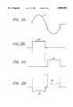
- FIG. 2Aillustrates the voltage waveform 17 measured across the terminals PQ of the secondary coil 6b of the transformer 6 of FIG. 1, when the primary coil 6a is energized by an AC voltage at the plug 1.
- FIG. 2Billustrates the gate voltage on devices 7 and 9 provided by the gate controller circuit 5 during the positive cycle of the voltage waveform 17 of FIG. 2A.
- FIG. 2Cillustrates the gate voltage on devices 8 and 10 provided by the gate controller circuit 5 during the negative cycle of the voltage waveform 17 of FIG. 2A.
- FIG. 2Dillustrates the output current waveform I PQ 20 resulting from the inverter operation
- FIG. 3is a schematic diagram of a second embodiment of the solar inverter circuit 2 of the present invention.
- FIG. 4Aillustrates the current-voltage relationship at the terminals of the solar cell array 3, having an open-circuit voltage value V OC .
- FIG. 4Billustrates the voltage waveform 21-1 developed across the terminals a and c of the solar cell array of FIG. 1.
- FIG. 4Cillustrates the voltage waveform 21-2 developed across the terminals a-c of the solar cell array 3 of FIG. 3 depicting the effect of discharging a DC current into the battery 4 and during the time interval t.
- FIG. 5illustrates one embodiment of the gate controller circuit 5 of FIGS. 1 and 3.
- FIG. 6illustrates an exemplary solar cell array which implements the solar inverter circuit 2 of the present invention.
- a novel solar inverter circuitis used to connect a solar photovoltaic (PV) array with an alternating current (AC) voltage source to convert direct current (DC) power from the PV array to AC power.
- the solar inverter circuitemploys the current-voltage (I-V) characteristic of the PV or solar cell, and an H-Bridge circuit with gate controller. The gate controller synchronizes the H-bridge with the AC voltage source.
- the PV array and the solar inverter circuitcan plug directly into a residential AC plug and provides electrical power as a supplementary AC supply. Electrical energy required by the home appliances is supplied by the municipal AC line and solar energy concurrently.
- Advantages of the solar inverter circuit of the present inventioninclude the flexibility of using the solar inverter circuit with any number of solar cell panels through the implementation of an impedance transformer, and the implementation of an additional, optional output for DC battery charging.
- FIG. 1is a schematic diagram of a first embodiment of the solar inverter circuit of the present invention.
- An alternating current (AC) sourceprovided via plug 1, provides an AC waveform to the solar inverter circuit 2.
- Solar energyis received by a solar photovoltaic array or a solar cell array 3, which in turn generates direct current (DC) power that is provided to the solar inverter circuit 2.
- ACalternating current
- DCdirect current
- the solar inverter circuit 2comprises an H-bridge circuit 2a and a transformer 6.
- the H-bridge circuit 2acomprises a gate controller circuit 5 and four switching devices 7, 8, 9 and 10.
- each switching device 7, 8, 9 and 10is a Field Effect Transistor (FET).
- FETField Effect Transistor
- each switching devicemay be an Insulated Gate Bipolar Transistor (IGBT), a Gate-Turn-Off thyristor (GTO), a Bipolar Junction Transistor (BJT), a Silicon-Controlled-Rectifier (SCR), a bidirectional triode thyristor (TRIAC), a MOS-Controlled Thyristor (MCT), or any other switching devices in which switching can be electronically controlled by applying appropriate signal to the gate terminal of the device.
- the chosen deviceis of sufficient current and voltage rating to be safely operating in the circuit.
- the H-bridge circuit 2aalso comprises four diodes D1, D2, D3 and D4.
- the transformer 6has a primary coil 6a and a secondary coil 6b.
- the transformer 6is an isolation transformer, in which the primary coil 6a and the secondary coil 6b are not DC-coupled, and is a well-known type of transformer.
- the gates of the four switching devices 7, 8, 9 and 10are controlled by the gate controller circuit 5.
- the input to the gate controller circuit 5is the voltage V PQ from the secondary coil of the isolation transformer 6. This voltage V PQ is derived from an AC source provided via plug 1.
- a detailed description of the gate controller circuit 5 and the transformer 6is provided in the following sections.
- the gate controller circuit 5issues a pulse such as the voltage waveform 18 shown in FIG. 2B to turn the switching devices 7 and 9 on and the switching devices 8 and 10 off.
- the signal path segments ab and efact as short circuits, while the signal path segments bc and de act as open circuits.
- the DC current generated by the solar cell array 3takes the signal path segment ab through the secondary coil of the transformer 6 from node P to node Q, and thence through to the signal path segment ef.
- the solar cell arraymay consist of a number of individual cells connected in series and parallel such that the current-voltage relationship at the array's terminals is shown in FIG. 4A.
- the voltage in FIG. 4Ais actually in the opposing direction with respect to the direction of the current flow I.
- the voltage V PQis the opposing voltage provided through the signal path segments, and the current at each instantaneous value of V PQ which is shown as 17 in FIG. 2A, is then shown as the current waveform 20 in FIG. 2D. It is important to note that the H-bridge circuit 2a in FIG.
- the negative conductance characteristic of the solar cell arrayi.e. the direction of the current I is opposite to that of the voltage V mentioned earlier in conjunction with FIG. 4A
- the current in the coil 6bflows in the opposite direction to V PQ
- the current in the coil 6aalso flows in the opposite direction to the plug (city plug) voltage, and thus AC power is delivered from the circuit 2a into the city AC power line, without influencing the city AC voltage.
- the diodes D1, D2, D3 and D4are implemented for safety reasons, such as to guard against short-circuiting if current from the solar cell array 3 flows in the wrong direction when the H-bridge circuit 2a malfunctions.
- FIG. 3illustrates a second embodiment of the solar inverter circuit of the present invention.
- the solar inverter circuit 2also provides a DC battery charging circuit.
- ta small period of time, during which all switching devices 7, 8, 9 and 10 in the H-bridge circuit 2a are in the off-state, so as to prevent mistriggering. Consequently, during this time interval, t, (as shown in FIG. 4B) the DC current from solar cell array 3 is not converted to AC current because there is no current flowing through PQ during t.
- FIG. 4Billustrates the voltage waveform 21-1 provided across the terminals a and c of the solar cell array 3 without the battery charging circuit 2b.
- the solar inverter circuit 2further comprises a battery charging circuit 2b.
- the battery charging circuit 2bcomprises a NOR gate 11, a switching device 12 and a diode D5.
- the output of the NOR gate 11goes high only when both the voltage waveforms 18 and 19 are off, i.e., during the time interval t, and is used to cause the switching device 12 to conduct during the time interval t.
- DC current from solar cell array 3then passes through the diode D5 and into the battery 4 and the DC current harnessed may be stored in the battery 4 through trickle charging.
- the voltage waveform developed across the terminals a-c of the solar cell array 3then becomes the waveform 21-2 as shown in FIG. 4C.
- FIG. 5illustrates one embodiment of the gate controller circuit 5 as shown in FIGS. 1 and 3.
- the input of the gate controller circuit 5is connected to the secondary turn of the isolation transformer 6, which provides V PQ , the voltage waveform 17 as shown in FIG. 2A.
- the bridge diode 23 and capacitor 32provide a DC supply for the circuit 5.
- the operational amplifiers 24 and 25are configured as voltage comparators, and each generate a square pulse in response to the input voltage waveform 17.
- the non-inverting terminal of operational amplifier 24is coupled to node P
- the non-inverting terminal of operational amplifier 25is coupled to node Q.
- the inverting terminals of each operational amplifier 24 and 25are coupled to a variable resistor 22, which allows the user to set the time interval t, as shown in FIGS.
- the output of operational amplifier 24is provided as an input to buffers 26 and 27, which in turn drive the gates of switching devices 7 and 9, respectively.
- the output of operational amplifier 25is provided as an input to buffers 28 and 29, which in turn generate outputs which drive the gates of switching devices 8 and 10, respectively.
- the buffers 26, 27, 28 and 29are used to increase driving current to the switching devices 7, 8, 9 and 10.
- the buffers 26, 27, 28 and 29are Schmitt triggers.
- the operational amplifier 24During the positive cycle of the waveform 17, the operational amplifier 24 generates a square pulse, which in turn drives the gates of switching devices 7 and 9, turning on the switching devices 7 and 9. During this cycle, the operational amplifier 25 does not generate any output, and thus, the switching devices 8 and 10 are not turned on. Thus, during the positive cycle, the switching devices 7 and 9 conduct, while the switching devices 8 and 10 do not conduct.
- the operational amplifier 25During the negative cycle of the waveform 17, the operational amplifier 25 generates a square pulse, which in turn drives the gates of switching devices 8 and 10, turning on the switching devices 8 and 10. During this negative cycle, the operational amplifier 24 does not generate any output, and thus, the switching devices 7 and 9 are not turned on. Thus, during the negative cycle, the switching devices 8 and 10 conduct and the switching devices 7 and 9 do not conduct.
- the width of the pulses 18 and 19are adjustable, and hence the time interval, t, between the pulses 18 and 19 is also adjustable, affecting the waveform 20 (FIG. 2D) and waveforms 21-1 and 21-2 (FIGS. 4B and 4C, respectively).
- the time duration t during which a battery is chargedcan thus be varied, say from 1% to 99%, with concurrent AC power production from 99% to 1% correspondingly. This feature allows the solar inverter circuit 2 to be readily adaptable to the local power consumption needs for immediate AC application as opposed to DC storage for immediate or later use.
- the isolation transformer 6In order to optimize the AC power from the solar cell array 3, the "open-circuit voltage" of the solar cell array 3 must be 5%-20% higher than the amplitude of V PQ . Because a single solar cell's open-circuit voltage V PQ is less than 1 volt and the "short-circuit current"I SC is only several milliamps, the solar cell array 3 may be commercially available (with series and parallel connected cells) with a specified set of V OC and I SC .
- the isolation transformer 6can be chosen with the transformer-turn-ratio to match the 220 V( AC ) with the V PQ needed for the optimal operation of the solar cell array 3. This allows the solar inverter circuit 2 of the present invention to provide 220 V(AC) from any available solar cell array 3, with an arbitrary combination of V OC and I SC .
- an appropriate transformer 6can be chosen not only to efficiently match the operation of an arbitrary solar cell array 3 to the city grid but also to match operation of the transformer 6 and the solar cell array 3 to any other AC generator, typically a diesel driven one or to an uninterrupted power supply (UPS). It is apparent to one skilled in the art that the consumer can purchase more solar cells to add on to the solar cell array 3 to harness and to generate more AC power from the sun at the user's own convenience and with minor adjustments to the transformer 6. Hence, the solar inverter circuit 2 of the present invention is both versatile and widely applicable.
- FIG. 6illustrates an exemplary solar cell array which implements the solar inverter circuit of the present invention.
- the solar inverter circuit 2may be mounted to the back of a solar cell array 3 panel.
- An AC source provided via plug 1provides an AC voltage waveform to the solar inverter circuit 2.
- Solar energyis received by the solar cell array 3, which in turn generates DC power that is provided to the solar inverter circuit 2.
- the solar inverter circuit 2in turn converts the DC power to AC power, which is returned to the AC source at plug 1.
- the solar inverter circuit 2may also comprise a battery charging circuit 2b which enables the solar inverter circuit 2 to also generate DC power for immediate DC applications or for storage in a battery 4.
- Implementation of the solar inverter circuit of the present inventionprovides: (i) conversion of DC solar power to AC power through reference to an AC voltage source, and (ii) generation of additional DC power. Once harnessed, both the AC and DC powers may be utilized immediately, or the DC portion may be stored for later use. The features of immediate applicability and/or storage of the power, along with the versatility of matching the solar power with any AC voltage reference source, enables the solar inverter circuit of the present invention to be used in many applications.
Landscapes
- Engineering & Computer Science (AREA)
- Power Engineering (AREA)
- Inverter Devices (AREA)
Abstract
Description
Claims (33)
Priority Applications (1)
| Application Number | Priority Date | Filing Date | Title |
|---|---|---|---|
| US08/865,228US5898585A (en) | 1997-05-29 | 1997-05-29 | Apparatus and method for providing supplemental alternating current from a solar cell array |
Applications Claiming Priority (1)
| Application Number | Priority Date | Filing Date | Title |
|---|---|---|---|
| US08/865,228US5898585A (en) | 1997-05-29 | 1997-05-29 | Apparatus and method for providing supplemental alternating current from a solar cell array |
Publications (1)
| Publication Number | Publication Date |
|---|---|
| US5898585Atrue US5898585A (en) | 1999-04-27 |
Family
ID=25345000
Family Applications (1)
| Application Number | Title | Priority Date | Filing Date |
|---|---|---|---|
| US08/865,228Expired - Fee RelatedUS5898585A (en) | 1997-05-29 | 1997-05-29 | Apparatus and method for providing supplemental alternating current from a solar cell array |
Country Status (1)
| Country | Link |
|---|---|
| US (1) | US5898585A (en) |
Cited By (94)
| Publication number | Priority date | Publication date | Assignee | Title |
|---|---|---|---|---|
| US6046919A (en)* | 1998-03-30 | 2000-04-04 | Sanyo Electric Co., Ltd. | Solar power generating device |
| NL1013874C2 (en)* | 1999-12-16 | 2001-06-21 | Mastervolt Solar B V | System and method for collecting solar energy. |
| US6329589B1 (en)* | 2000-03-21 | 2001-12-11 | John Wing-Yan Tang | Solar panel |
| US6367259B1 (en)* | 2000-02-15 | 2002-04-09 | Miguel A. Timm | Battery-less solar power system |
| US6617913B1 (en) | 2001-08-27 | 2003-09-09 | Unisys Corporation | Self-latching H-bridge system and apparatus |
| US6774299B2 (en) | 2002-08-16 | 2004-08-10 | Jorge Ford | Solar electric alternating current generator |
| US20070221267A1 (en)* | 2006-03-23 | 2007-09-27 | Pvi Solutions Inc. | Method and apparatus for converting direct current to alternating current |
| DE102006016501A1 (en)* | 2006-04-07 | 2008-01-17 | Siemens Ag | The power semiconductor module |
| US20080084645A1 (en)* | 2006-10-04 | 2008-04-10 | Ahmad Nemer Jr | Emergency solar power supply |
| CN100394689C (en)* | 2002-12-12 | 2008-06-11 | 立錡科技股份有限公司 | two-phase H-bridge driving circuit and method |
| US20090218887A1 (en)* | 2007-10-15 | 2009-09-03 | And, Llc | Systems for Highly Efficient Solar Power Conversion |
| US20100213768A1 (en)* | 2009-02-24 | 2010-08-26 | Alex Faveluke | Apparatus for photovoltaic power generation |
| US20100246230A1 (en)* | 2007-10-23 | 2010-09-30 | Ampt, Llc | High reliability power systems and solar power converters |
| US7977818B1 (en) | 2011-01-25 | 2011-07-12 | Wahl Eric R | Safety device for plug and play solar energy system |
| US20110205766A1 (en)* | 2004-11-08 | 2011-08-25 | Cuauhtemoc Rodriguez | Power Conditioning Unit |
| US20110210611A1 (en)* | 2008-10-10 | 2011-09-01 | Ampt, Llc | Novel Solar Power Circuits |
| US20110238231A1 (en)* | 2008-12-17 | 2011-09-29 | 4 Front Engineered Solutions, Inc. | Alternative power operation of loading docks and loading dock equipment |
| US8378656B2 (en) | 2008-09-19 | 2013-02-19 | General Electric Company | Quasi-AC, photovoltaic module for unfolder photovoltaic inverter |
| WO2013104290A1 (en)* | 2012-01-10 | 2013-07-18 | Rong Yun | Photo-thermal mixed utilization system for solar energy |
| US8552587B2 (en) | 2010-07-20 | 2013-10-08 | Igrenenergi Semiconductor Technologies Pvt. Ltd. | Power conversion for distributed DC source array |
| EP2667466A3 (en)* | 2012-05-25 | 2014-02-19 | EnWi-Etec GmbH | Pre-assembled photovoltaic assembly connection cabinet |
| WO2015112531A1 (en)* | 2014-01-27 | 2015-07-30 | Netronex, Inc. | Ac motor drive powered concurrently by ac grid and dc solar array |
| US9106150B2 (en)* | 2011-12-02 | 2015-08-11 | Darfon Electronics Corp. | Battery free off-grid solar inverter system and control method thereof |
| US9112379B2 (en) | 2006-12-06 | 2015-08-18 | Solaredge Technologies Ltd. | Pairing of components in a direct current distributed power generation system |
| US9130401B2 (en) | 2006-12-06 | 2015-09-08 | Solaredge Technologies Ltd. | Distributed power harvesting systems using DC power sources |
| US9235228B2 (en) | 2012-03-05 | 2016-01-12 | Solaredge Technologies Ltd. | Direct current link circuit |
| US9291696B2 (en) | 2007-12-05 | 2016-03-22 | Solaredge Technologies Ltd. | Photovoltaic system power tracking method |
| US9318974B2 (en) | 2014-03-26 | 2016-04-19 | Solaredge Technologies Ltd. | Multi-level inverter with flying capacitor topology |
| US9362743B2 (en) | 2008-05-05 | 2016-06-07 | Solaredge Technologies Ltd. | Direct current power combiner |
| US9368964B2 (en) | 2006-12-06 | 2016-06-14 | Solaredge Technologies Ltd. | Distributed power system using direct current power sources |
| US9397497B2 (en) | 2013-03-15 | 2016-07-19 | Ampt, Llc | High efficiency interleaved solar power supply system |
| US9401599B2 (en) | 2010-12-09 | 2016-07-26 | Solaredge Technologies Ltd. | Disconnection of a string carrying direct current power |
| US9407161B2 (en) | 2007-12-05 | 2016-08-02 | Solaredge Technologies Ltd. | Parallel connected inverters |
| US9436198B2 (en) | 2006-03-23 | 2016-09-06 | Enphase Energy, Inc. | Method and apparatus for power conversion |
| US9442504B2 (en) | 2009-04-17 | 2016-09-13 | Ampt, Llc | Methods and apparatus for adaptive operation of solar power systems |
| US9461552B2 (en) | 2006-03-23 | 2016-10-04 | Enphase Energy, Inc. | Method and apparatus for power conversion |
| US9466737B2 (en) | 2009-10-19 | 2016-10-11 | Ampt, Llc | Solar panel string converter topology |
| US9537445B2 (en) | 2008-12-04 | 2017-01-03 | Solaredge Technologies Ltd. | Testing of a photovoltaic panel |
| US9543889B2 (en) | 2006-12-06 | 2017-01-10 | Solaredge Technologies Ltd. | Distributed power harvesting systems using DC power sources |
| US9548619B2 (en) | 2013-03-14 | 2017-01-17 | Solaredge Technologies Ltd. | Method and apparatus for storing and depleting energy |
| CN106451694A (en)* | 2015-07-30 | 2017-02-22 | 苏州大禾能源技术有限公司 | Reversal charging circuit for power frequency inverter power supply |
| US9590526B2 (en) | 2006-12-06 | 2017-03-07 | Solaredge Technologies Ltd. | Safety mechanisms, wake up and shutdown methods in distributed power installations |
| US9644993B2 (en) | 2006-12-06 | 2017-05-09 | Solaredge Technologies Ltd. | Monitoring of distributed power harvesting systems using DC power sources |
| US9647442B2 (en) | 2010-11-09 | 2017-05-09 | Solaredge Technologies Ltd. | Arc detection and prevention in a power generation system |
| US9673711B2 (en) | 2007-08-06 | 2017-06-06 | Solaredge Technologies Ltd. | Digital average input current control in power converter |
| US9680304B2 (en) | 2006-12-06 | 2017-06-13 | Solaredge Technologies Ltd. | Method for distributed power harvesting using DC power sources |
| US9812984B2 (en) | 2012-01-30 | 2017-11-07 | Solaredge Technologies Ltd. | Maximizing power in a photovoltaic distributed power system |
| US9819178B2 (en) | 2013-03-15 | 2017-11-14 | Solaredge Technologies Ltd. | Bypass mechanism |
| US9831824B2 (en) | 2007-12-05 | 2017-11-28 | SolareEdge Technologies Ltd. | Current sensing on a MOSFET |
| US9853538B2 (en) | 2007-12-04 | 2017-12-26 | Solaredge Technologies Ltd. | Distributed power harvesting systems using DC power sources |
| US9853565B2 (en) | 2012-01-30 | 2017-12-26 | Solaredge Technologies Ltd. | Maximized power in a photovoltaic distributed power system |
| US9866098B2 (en) | 2011-01-12 | 2018-01-09 | Solaredge Technologies Ltd. | Serially connected inverters |
| US9869701B2 (en) | 2009-05-26 | 2018-01-16 | Solaredge Technologies Ltd. | Theft detection and prevention in a power generation system |
| US9876430B2 (en) | 2008-03-24 | 2018-01-23 | Solaredge Technologies Ltd. | Zero voltage switching |
| US9923516B2 (en) | 2012-01-30 | 2018-03-20 | Solaredge Technologies Ltd. | Photovoltaic panel circuitry |
| US9941813B2 (en) | 2013-03-14 | 2018-04-10 | Solaredge Technologies Ltd. | High frequency multi-level inverter |
| US9960667B2 (en) | 2006-12-06 | 2018-05-01 | Solaredge Technologies Ltd. | System and method for protection during inverter shutdown in distributed power installations |
| US9966766B2 (en) | 2006-12-06 | 2018-05-08 | Solaredge Technologies Ltd. | Battery power delivery module |
| US10069457B2 (en) | 2015-05-20 | 2018-09-04 | General Electric Company | System for mounting a microinverter to a photovoltaic panel and method of making same |
| US10081504B2 (en) | 2014-05-02 | 2018-09-25 | Assa Abloy Entrance Systems Ab | Systems and methods for automatically controlling loading dock equipment |
| US10115841B2 (en) | 2012-06-04 | 2018-10-30 | Solaredge Technologies Ltd. | Integrated photovoltaic panel circuitry |
| US10230310B2 (en) | 2016-04-05 | 2019-03-12 | Solaredge Technologies Ltd | Safety switch for photovoltaic systems |
| US10396662B2 (en) | 2011-09-12 | 2019-08-27 | Solaredge Technologies Ltd | Direct current link circuit |
| US10494205B1 (en) | 2018-12-06 | 2019-12-03 | Assa Abloy Entrance Systems Ab | Remote loading dock authorization systems and methods |
| US10673222B2 (en) | 2010-11-09 | 2020-06-02 | Solaredge Technologies Ltd. | Arc detection and prevention in a power generation system |
| US10673229B2 (en) | 2010-11-09 | 2020-06-02 | Solaredge Technologies Ltd. | Arc detection and prevention in a power generation system |
| US10878386B2 (en) | 2018-11-26 | 2020-12-29 | Assa Abloy Entrance Systems Ab | Systems and methods for automated dock station servicing |
| US10931119B2 (en) | 2012-01-11 | 2021-02-23 | Solaredge Technologies Ltd. | Photovoltaic module |
| US11018623B2 (en) | 2016-04-05 | 2021-05-25 | Solaredge Technologies Ltd. | Safety switch for photovoltaic systems |
| US11142413B2 (en) | 2019-01-28 | 2021-10-12 | Assa Abloy Entrance Systems Ab | Systems and methods for automated loading and unloading at a dock station |
| US11177663B2 (en) | 2016-04-05 | 2021-11-16 | Solaredge Technologies Ltd. | Chain of power devices |
| US11225824B2 (en) | 2016-05-03 | 2022-01-18 | Assa Abloy Entrance Systems Ab | Control systems for operation of loading dock equipment, and associated methods of manufacture and use |
| US11262747B2 (en) | 2019-06-11 | 2022-03-01 | Assa Abloy Entrance Systems Ab | Vehicle identification and guidance systems and associated methods |
| US11264947B2 (en) | 2007-12-05 | 2022-03-01 | Solaredge Technologies Ltd. | Testing of a photovoltaic panel |
| US11296650B2 (en) | 2006-12-06 | 2022-04-05 | Solaredge Technologies Ltd. | System and method for protection during inverter shutdown in distributed power installations |
| US11309832B2 (en) | 2006-12-06 | 2022-04-19 | Solaredge Technologies Ltd. | Distributed power harvesting systems using DC power sources |
| US11305953B2 (en) | 2016-05-03 | 2022-04-19 | Assa Abloy Entrance Systems Ab | Control systems for operation of loading dock equipment, and associated methods of manufacture and use |
| US11358813B2 (en) | 2014-05-02 | 2022-06-14 | Assa Abloy Entrance Systems Ab | Systems and methods for automatically controlling loading dock equipment |
| US11460488B2 (en) | 2017-08-14 | 2022-10-04 | Koolbridge Solar, Inc. | AC electrical power measurements |
| US11509163B2 (en) | 2011-05-08 | 2022-11-22 | Koolbridge Solar, Inc. | Multi-level DC to AC inverter |
| US11569660B2 (en) | 2006-12-06 | 2023-01-31 | Solaredge Technologies Ltd. | Distributed power harvesting systems using DC power sources |
| US11569659B2 (en) | 2006-12-06 | 2023-01-31 | Solaredge Technologies Ltd. | Distributed power harvesting systems using DC power sources |
| US11687112B2 (en) | 2006-12-06 | 2023-06-27 | Solaredge Technologies Ltd. | Distributed power harvesting systems using DC power sources |
| US11728768B2 (en) | 2006-12-06 | 2023-08-15 | Solaredge Technologies Ltd. | Pairing of components in a direct current distributed power generation system |
| US11735910B2 (en) | 2006-12-06 | 2023-08-22 | Solaredge Technologies Ltd. | Distributed power system using direct current power sources |
| US11855231B2 (en) | 2006-12-06 | 2023-12-26 | Solaredge Technologies Ltd. | Distributed power harvesting systems using DC power sources |
| US11881814B2 (en) | 2005-12-05 | 2024-01-23 | Solaredge Technologies Ltd. | Testing of a photovoltaic panel |
| US11888387B2 (en) | 2006-12-06 | 2024-01-30 | Solaredge Technologies Ltd. | Safety mechanisms, wake up and shutdown methods in distributed power installations |
| US11901810B2 (en) | 2011-05-08 | 2024-02-13 | Koolbridge Solar, Inc. | Adaptive electrical power distribution panel |
| US12057807B2 (en) | 2016-04-05 | 2024-08-06 | Solaredge Technologies Ltd. | Chain of power devices |
| US12338672B2 (en) | 2021-07-02 | 2025-06-24 | Assa Abloy Entrance Systems Ab | Powered trailer systems |
| US12362647B2 (en) | 2011-05-08 | 2025-07-15 | Koolbridge Solar, Inc. | Solar energy system with variable priority circuit backup |
| US12400175B2 (en) | 2021-11-30 | 2025-08-26 | Assa Abloy Entrance Systems Ab | Trailer validation systems |
| US12418177B2 (en) | 2009-10-24 | 2025-09-16 | Solaredge Technologies Ltd. | Distributed power system using direct current power sources |
Citations (10)
| Publication number | Priority date | Publication date | Assignee | Title |
|---|---|---|---|---|
| US3946242A (en)* | 1975-03-03 | 1976-03-23 | Wilkerson A W | Geophysical energy source utilization circuit |
| US4445049A (en)* | 1981-12-28 | 1984-04-24 | General Electric Company | Inverter for interfacing advanced energy sources to a utility grid |
| US4680690A (en)* | 1984-10-19 | 1987-07-14 | Dickerson Arthur F | Inverter for use with solar arrays |
| JPS63124771A (en)* | 1986-11-14 | 1988-05-28 | Shikoku Electric Power Co Inc | Inverter device |
| US5268832A (en)* | 1991-08-20 | 1993-12-07 | Kabushiki Kaisha Toshiba | DC/AC inverter controller for solar cell, including maximum power point tracking function |
| US5493485A (en)* | 1992-06-24 | 1996-02-20 | Kabushiki Kaisha Toshiba | Protection device for stopping operation of an inverter |
| US5625539A (en)* | 1994-05-30 | 1997-04-29 | Sharp Kabushiki Kaisha | Method and apparatus for controlling a DC to AC inverter system by a plurality of pulse-width modulated pulse trains |
| US5668713A (en)* | 1995-10-16 | 1997-09-16 | Sharp Kabushiki Kaisha | Inverter control method and inverter control device performing feedback control by suppressing delay |
| US5677833A (en)* | 1995-05-16 | 1997-10-14 | Raytheon Company | Power conditioning system for a four quadrant photovoltaic array with an inverter for each array quadrant |
| US5719758A (en)* | 1995-12-20 | 1998-02-17 | Sharp Kabushiki Kaisha | Inverter control method and inverter apparatus using the method |
- 1997
- 1997-05-29USUS08/865,228patent/US5898585A/ennot_activeExpired - Fee Related
Patent Citations (10)
| Publication number | Priority date | Publication date | Assignee | Title |
|---|---|---|---|---|
| US3946242A (en)* | 1975-03-03 | 1976-03-23 | Wilkerson A W | Geophysical energy source utilization circuit |
| US4445049A (en)* | 1981-12-28 | 1984-04-24 | General Electric Company | Inverter for interfacing advanced energy sources to a utility grid |
| US4680690A (en)* | 1984-10-19 | 1987-07-14 | Dickerson Arthur F | Inverter for use with solar arrays |
| JPS63124771A (en)* | 1986-11-14 | 1988-05-28 | Shikoku Electric Power Co Inc | Inverter device |
| US5268832A (en)* | 1991-08-20 | 1993-12-07 | Kabushiki Kaisha Toshiba | DC/AC inverter controller for solar cell, including maximum power point tracking function |
| US5493485A (en)* | 1992-06-24 | 1996-02-20 | Kabushiki Kaisha Toshiba | Protection device for stopping operation of an inverter |
| US5625539A (en)* | 1994-05-30 | 1997-04-29 | Sharp Kabushiki Kaisha | Method and apparatus for controlling a DC to AC inverter system by a plurality of pulse-width modulated pulse trains |
| US5677833A (en)* | 1995-05-16 | 1997-10-14 | Raytheon Company | Power conditioning system for a four quadrant photovoltaic array with an inverter for each array quadrant |
| US5668713A (en)* | 1995-10-16 | 1997-09-16 | Sharp Kabushiki Kaisha | Inverter control method and inverter control device performing feedback control by suppressing delay |
| US5719758A (en)* | 1995-12-20 | 1998-02-17 | Sharp Kabushiki Kaisha | Inverter control method and inverter apparatus using the method |
Cited By (257)
| Publication number | Priority date | Publication date | Assignee | Title |
|---|---|---|---|---|
| US6046919A (en)* | 1998-03-30 | 2000-04-04 | Sanyo Electric Co., Ltd. | Solar power generating device |
| NL1013874C2 (en)* | 1999-12-16 | 2001-06-21 | Mastervolt Solar B V | System and method for collecting solar energy. |
| WO2001045179A1 (en)* | 1999-12-16 | 2001-06-21 | Mastervolt Solar B.V. | System and method for collecting solar energy |
| US6367259B1 (en)* | 2000-02-15 | 2002-04-09 | Miguel A. Timm | Battery-less solar power system |
| US6329589B1 (en)* | 2000-03-21 | 2001-12-11 | John Wing-Yan Tang | Solar panel |
| US6617913B1 (en) | 2001-08-27 | 2003-09-09 | Unisys Corporation | Self-latching H-bridge system and apparatus |
| US6774299B2 (en) | 2002-08-16 | 2004-08-10 | Jorge Ford | Solar electric alternating current generator |
| CN100394689C (en)* | 2002-12-12 | 2008-06-11 | 立錡科技股份有限公司 | two-phase H-bridge driving circuit and method |
| US9473038B2 (en) | 2004-11-08 | 2016-10-18 | Solarcity Corporation | Power conditioning unit with voltage converters |
| US8369113B2 (en) | 2004-11-08 | 2013-02-05 | Enecsys Limited | Power conditioning unit |
| US20110205766A1 (en)* | 2004-11-08 | 2011-08-25 | Cuauhtemoc Rodriguez | Power Conditioning Unit |
| US10033292B2 (en) | 2004-11-08 | 2018-07-24 | Solarcity Corporation | Power conditioning unit with voltage converters |
| US9831794B2 (en) | 2004-11-08 | 2017-11-28 | Solarcity Corporation | Power conditioning unit with voltage converters |
| US8971082B2 (en) | 2004-11-08 | 2015-03-03 | Enecsys Limited | Power conditioning unit with voltage converters |
| US11881814B2 (en) | 2005-12-05 | 2024-01-23 | Solaredge Technologies Ltd. | Testing of a photovoltaic panel |
| US20070221267A1 (en)* | 2006-03-23 | 2007-09-27 | Pvi Solutions Inc. | Method and apparatus for converting direct current to alternating current |
| US7796412B2 (en) | 2006-03-23 | 2010-09-14 | Enphase Energy, Inc. | Method and apparatus for converting direct current to alternating current |
| US9461552B2 (en) | 2006-03-23 | 2016-10-04 | Enphase Energy, Inc. | Method and apparatus for power conversion |
| US9436198B2 (en) | 2006-03-23 | 2016-09-06 | Enphase Energy, Inc. | Method and apparatus for power conversion |
| US8717780B2 (en) | 2006-03-23 | 2014-05-06 | Enphase Energy, Inc. | Method and apparatus for converting direct current to alternating current |
| US20110012429A1 (en)* | 2006-03-23 | 2011-01-20 | Enphase Energy, Inc. | Method and apparatus for converting direct current to alternating current |
| DE102006016501A1 (en)* | 2006-04-07 | 2008-01-17 | Siemens Ag | The power semiconductor module |
| US20080084645A1 (en)* | 2006-10-04 | 2008-04-10 | Ahmad Nemer Jr | Emergency solar power supply |
| US11579235B2 (en) | 2006-12-06 | 2023-02-14 | Solaredge Technologies Ltd. | Safety mechanisms, wake up and shutdown methods in distributed power installations |
| US9590526B2 (en) | 2006-12-06 | 2017-03-07 | Solaredge Technologies Ltd. | Safety mechanisms, wake up and shutdown methods in distributed power installations |
| US12316274B2 (en) | 2006-12-06 | 2025-05-27 | Solaredge Technologies Ltd. | Pairing of components in a direct current distributed power generation system |
| US11309832B2 (en) | 2006-12-06 | 2022-04-19 | Solaredge Technologies Ltd. | Distributed power harvesting systems using DC power sources |
| US11296650B2 (en) | 2006-12-06 | 2022-04-05 | Solaredge Technologies Ltd. | System and method for protection during inverter shutdown in distributed power installations |
| US10447150B2 (en) | 2006-12-06 | 2019-10-15 | Solaredge Technologies Ltd. | Distributed power harvesting systems using DC power sources |
| US11031861B2 (en) | 2006-12-06 | 2021-06-08 | Solaredge Technologies Ltd. | System and method for protection during inverter shutdown in distributed power installations |
| US12281919B2 (en) | 2006-12-06 | 2025-04-22 | Solaredge Technologies Ltd. | Monitoring of distributed power harvesting systems using DC power sources |
| US11476799B2 (en) | 2006-12-06 | 2022-10-18 | Solaredge Technologies Ltd. | Distributed power harvesting systems using DC power sources |
| US11569660B2 (en) | 2006-12-06 | 2023-01-31 | Solaredge Technologies Ltd. | Distributed power harvesting systems using DC power sources |
| US11569659B2 (en) | 2006-12-06 | 2023-01-31 | Solaredge Technologies Ltd. | Distributed power harvesting systems using DC power sources |
| US12276997B2 (en) | 2006-12-06 | 2025-04-15 | Solaredge Technologies Ltd. | Distributed power harvesting systems using DC power sources |
| US11575261B2 (en) | 2006-12-06 | 2023-02-07 | Solaredge Technologies Ltd. | Distributed power harvesting systems using DC power sources |
| US11043820B2 (en) | 2006-12-06 | 2021-06-22 | Solaredge Technologies Ltd. | Battery power delivery module |
| US10230245B2 (en) | 2006-12-06 | 2019-03-12 | Solaredge Technologies Ltd | Battery power delivery module |
| US11575260B2 (en) | 2006-12-06 | 2023-02-07 | Solaredge Technologies Ltd. | Distributed power harvesting systems using DC power sources |
| US12224706B2 (en) | 2006-12-06 | 2025-02-11 | Solaredge Technologies Ltd. | Pairing of components in a direct current distributed power generation system |
| US11063440B2 (en) | 2006-12-06 | 2021-07-13 | Solaredge Technologies Ltd. | Method for distributed power harvesting using DC power sources |
| US12107417B2 (en) | 2006-12-06 | 2024-10-01 | Solaredge Technologies Ltd. | Distributed power harvesting systems using DC power sources |
| US11002774B2 (en) | 2006-12-06 | 2021-05-11 | Solaredge Technologies Ltd. | Monitoring of distributed power harvesting systems using DC power sources |
| US12068599B2 (en) | 2006-12-06 | 2024-08-20 | Solaredge Technologies Ltd. | System and method for protection during inverter shutdown in distributed power installations |
| US10097007B2 (en) | 2006-12-06 | 2018-10-09 | Solaredge Technologies Ltd. | Method for distributed power harvesting using DC power sources |
| US11594882B2 (en) | 2006-12-06 | 2023-02-28 | Solaredge Technologies Ltd. | Distributed power harvesting systems using DC power sources |
| US12046940B2 (en) | 2006-12-06 | 2024-07-23 | Solaredge Technologies Ltd. | Battery power control |
| US9112379B2 (en) | 2006-12-06 | 2015-08-18 | Solaredge Technologies Ltd. | Pairing of components in a direct current distributed power generation system |
| US9130401B2 (en) | 2006-12-06 | 2015-09-08 | Solaredge Technologies Ltd. | Distributed power harvesting systems using DC power sources |
| US12032080B2 (en) | 2006-12-06 | 2024-07-09 | Solaredge Technologies Ltd. | Safety mechanisms, wake up and shutdown methods in distributed power installations |
| US11594881B2 (en) | 2006-12-06 | 2023-02-28 | Solaredge Technologies Ltd. | Distributed power harvesting systems using DC power sources |
| US11594880B2 (en) | 2006-12-06 | 2023-02-28 | Solaredge Technologies Ltd. | Distributed power harvesting systems using DC power sources |
| US10637393B2 (en) | 2006-12-06 | 2020-04-28 | Solaredge Technologies Ltd. | Distributed power harvesting systems using DC power sources |
| US9368964B2 (en) | 2006-12-06 | 2016-06-14 | Solaredge Technologies Ltd. | Distributed power system using direct current power sources |
| US12027849B2 (en) | 2006-12-06 | 2024-07-02 | Solaredge Technologies Ltd. | Distributed power system using direct current power sources |
| US12027970B2 (en) | 2006-12-06 | 2024-07-02 | Solaredge Technologies Ltd. | Safety mechanisms, wake up and shutdown methods in distributed power installations |
| US11073543B2 (en) | 2006-12-06 | 2021-07-27 | Solaredge Technologies Ltd. | Monitoring of distributed power harvesting systems using DC power sources |
| US9966766B2 (en) | 2006-12-06 | 2018-05-08 | Solaredge Technologies Ltd. | Battery power delivery module |
| US9960731B2 (en) | 2006-12-06 | 2018-05-01 | Solaredge Technologies Ltd. | Pairing of components in a direct current distributed power generation system |
| US9960667B2 (en) | 2006-12-06 | 2018-05-01 | Solaredge Technologies Ltd. | System and method for protection during inverter shutdown in distributed power installations |
| US9948233B2 (en) | 2006-12-06 | 2018-04-17 | Solaredge Technologies Ltd. | Distributed power harvesting systems using DC power sources |
| US11598652B2 (en) | 2006-12-06 | 2023-03-07 | Solaredge Technologies Ltd. | Monitoring of distributed power harvesting systems using DC power sources |
| US12388492B2 (en) | 2006-12-06 | 2025-08-12 | Solaredge Technologies Ltd. | Safety mechanisms, wake up and shutdown methods in distributed power installations |
| US11658482B2 (en) | 2006-12-06 | 2023-05-23 | Solaredge Technologies Ltd. | Distributed power harvesting systems using DC power sources |
| US9543889B2 (en) | 2006-12-06 | 2017-01-10 | Solaredge Technologies Ltd. | Distributed power harvesting systems using DC power sources |
| US11961922B2 (en) | 2006-12-06 | 2024-04-16 | Solaredge Technologies Ltd. | Distributed power harvesting systems using DC power sources |
| US11962243B2 (en) | 2006-12-06 | 2024-04-16 | Solaredge Technologies Ltd. | Method for distributed power harvesting using DC power sources |
| US11183922B2 (en) | 2006-12-06 | 2021-11-23 | Solaredge Technologies Ltd. | Distributed power harvesting systems using DC power sources |
| US11682918B2 (en) | 2006-12-06 | 2023-06-20 | Solaredge Technologies Ltd. | Battery power delivery module |
| US11888387B2 (en) | 2006-12-06 | 2024-01-30 | Solaredge Technologies Ltd. | Safety mechanisms, wake up and shutdown methods in distributed power installations |
| US9644993B2 (en) | 2006-12-06 | 2017-05-09 | Solaredge Technologies Ltd. | Monitoring of distributed power harvesting systems using DC power sources |
| US11687112B2 (en) | 2006-12-06 | 2023-06-27 | Solaredge Technologies Ltd. | Distributed power harvesting systems using DC power sources |
| US10673253B2 (en) | 2006-12-06 | 2020-06-02 | Solaredge Technologies Ltd. | Battery power delivery module |
| US11728768B2 (en) | 2006-12-06 | 2023-08-15 | Solaredge Technologies Ltd. | Pairing of components in a direct current distributed power generation system |
| US9680304B2 (en) | 2006-12-06 | 2017-06-13 | Solaredge Technologies Ltd. | Method for distributed power harvesting using DC power sources |
| US11855231B2 (en) | 2006-12-06 | 2023-12-26 | Solaredge Technologies Ltd. | Distributed power harvesting systems using DC power sources |
| US11735910B2 (en) | 2006-12-06 | 2023-08-22 | Solaredge Technologies Ltd. | Distributed power system using direct current power sources |
| US9853490B2 (en) | 2006-12-06 | 2017-12-26 | Solaredge Technologies Ltd. | Distributed power system using direct current power sources |
| US8093756B2 (en) | 2007-02-15 | 2012-01-10 | Ampt, Llc | AC power systems for renewable electrical energy |
| US20100253150A1 (en)* | 2007-02-15 | 2010-10-07 | Ampt, Llc | AC Power Systems for Renewable Electrical Energy |
| US10516336B2 (en) | 2007-08-06 | 2019-12-24 | Solaredge Technologies Ltd. | Digital average input current control in power converter |
| US10116217B2 (en) | 2007-08-06 | 2018-10-30 | Solaredge Technologies Ltd. | Digital average input current control in power converter |
| US9673711B2 (en) | 2007-08-06 | 2017-06-06 | Solaredge Technologies Ltd. | Digital average input current control in power converter |
| US11594968B2 (en) | 2007-08-06 | 2023-02-28 | Solaredge Technologies Ltd. | Digital average input current control in power converter |
| US10886746B1 (en) | 2007-10-15 | 2021-01-05 | Ampt, Llc | Alternating conversion solar power system |
| US11070063B2 (en) | 2007-10-15 | 2021-07-20 | Ampt, Llc | Method for alternating conversion solar power |
| US7719140B2 (en) | 2007-10-15 | 2010-05-18 | Ampt, Llc | Systems for boundary controlled solar power conversion |
| US12003110B2 (en) | 2007-10-15 | 2024-06-04 | Ampt, Llc | Optimized conversion system |
| US20100229915A1 (en)* | 2007-10-15 | 2010-09-16 | Ampt, Llc | Systems for Highly Efficient Solar Power |
| US12027867B2 (en) | 2007-10-15 | 2024-07-02 | Ampt, Llc | Coordinated converter reactively altering disabling photovoltaic electrical energy power system |
| US10608437B2 (en) | 2007-10-15 | 2020-03-31 | Ampt, Llc | Feedback based photovoltaic conversion systems |
| US9438037B2 (en) | 2007-10-15 | 2016-09-06 | Ampt, Llc | Systems for optimized solar power inversion |
| US11070062B2 (en) | 2007-10-15 | 2021-07-20 | Ampt, Llc | Photovoltaic conversion systems |
| US12027869B2 (en) | 2007-10-15 | 2024-07-02 | Ampt, Llc | Optimized photovoltaic conversion configuration |
| US11228182B2 (en) | 2007-10-15 | 2022-01-18 | Ampt, Llc | Converter disabling photovoltaic electrical energy power system |
| US20090218887A1 (en)* | 2007-10-15 | 2009-09-03 | And, Llc | Systems for Highly Efficient Solar Power Conversion |
| US20100038968A1 (en)* | 2007-10-15 | 2010-02-18 | Ampt, Llc | Systems for Boundary Controlled Solar Power Conversion |
| US11289917B1 (en) | 2007-10-15 | 2022-03-29 | Ampt, Llc | Optimized photovoltaic conversion system |
| US9673630B2 (en) | 2007-10-15 | 2017-06-06 | Ampt, Llc | Protected conversion solar power system |
| US7843085B2 (en) | 2007-10-15 | 2010-11-30 | Ampt, Llc | Systems for highly efficient solar power |
| US7605498B2 (en)* | 2007-10-15 | 2009-10-20 | Ampt, Llc | Systems for highly efficient solar power conversion |
| US8482153B2 (en) | 2007-10-15 | 2013-07-09 | Ampt, Llc | Systems for optimized solar power inversion |
| US8004116B2 (en) | 2007-10-15 | 2011-08-23 | Ampt, Llc | Highly efficient solar power systems |
| US20100308662A1 (en)* | 2007-10-15 | 2010-12-09 | Ampt, Llc | High Efficiency Remotely Controllable Solar Energy System |
| US10326283B2 (en) | 2007-10-15 | 2019-06-18 | Ampt, Llc | Converter intuitive photovoltaic electrical energy power system |
| US8304932B2 (en) | 2007-10-15 | 2012-11-06 | Ampt, Llc | Efficient solar energy power creation systems |
| US8242634B2 (en) | 2007-10-15 | 2012-08-14 | Ampt, Llc | High efficiency remotely controllable solar energy system |
| US20110067745A1 (en)* | 2007-10-15 | 2011-03-24 | Ampt, Llc | Highly Efficient Solar Power Systems |
| US7919953B2 (en) | 2007-10-23 | 2011-04-05 | Ampt, Llc | Solar power capacitor alternative switch circuitry system for enhanced capacitor life |
| US8461811B2 (en) | 2007-10-23 | 2013-06-11 | Ampt, Llc | Power capacitor alternative switch circuitry system for enhanced capacitor life |
| US20100246230A1 (en)* | 2007-10-23 | 2010-09-30 | Ampt, Llc | High reliability power systems and solar power converters |
| US20110181251A1 (en)* | 2007-10-23 | 2011-07-28 | Ampt, Llc | Alternative Switch Power Circuitry Systems |
| US9853538B2 (en) | 2007-12-04 | 2017-12-26 | Solaredge Technologies Ltd. | Distributed power harvesting systems using DC power sources |
| US9407161B2 (en) | 2007-12-05 | 2016-08-02 | Solaredge Technologies Ltd. | Parallel connected inverters |
| US11894806B2 (en) | 2007-12-05 | 2024-02-06 | Solaredge Technologies Ltd. | Testing of a photovoltaic panel |
| US9979280B2 (en) | 2007-12-05 | 2018-05-22 | Solaredge Technologies Ltd. | Parallel connected inverters |
| US10693415B2 (en) | 2007-12-05 | 2020-06-23 | Solaredge Technologies Ltd. | Testing of a photovoltaic panel |
| US12055647B2 (en) | 2007-12-05 | 2024-08-06 | Solaredge Technologies Ltd. | Parallel connected inverters |
| US11264947B2 (en) | 2007-12-05 | 2022-03-01 | Solaredge Technologies Ltd. | Testing of a photovoltaic panel |
| US11693080B2 (en) | 2007-12-05 | 2023-07-04 | Solaredge Technologies Ltd. | Parallel connected inverters |
| US9831824B2 (en) | 2007-12-05 | 2017-11-28 | SolareEdge Technologies Ltd. | Current sensing on a MOSFET |
| US9291696B2 (en) | 2007-12-05 | 2016-03-22 | Solaredge Technologies Ltd. | Photovoltaic system power tracking method |
| US11183923B2 (en) | 2007-12-05 | 2021-11-23 | Solaredge Technologies Ltd. | Parallel connected inverters |
| US10644589B2 (en) | 2007-12-05 | 2020-05-05 | Solaredge Technologies Ltd. | Parallel connected inverters |
| US11183969B2 (en) | 2007-12-05 | 2021-11-23 | Solaredge Technologies Ltd. | Testing of a photovoltaic panel |
| US9876430B2 (en) | 2008-03-24 | 2018-01-23 | Solaredge Technologies Ltd. | Zero voltage switching |
| US10468878B2 (en) | 2008-05-05 | 2019-11-05 | Solaredge Technologies Ltd. | Direct current power combiner |
| US9362743B2 (en) | 2008-05-05 | 2016-06-07 | Solaredge Technologies Ltd. | Direct current power combiner |
| US11424616B2 (en) | 2008-05-05 | 2022-08-23 | Solaredge Technologies Ltd. | Direct current power combiner |
| US12218498B2 (en) | 2008-05-05 | 2025-02-04 | Solaredge Technologies Ltd. | Direct current power combiner |
| US8378656B2 (en) | 2008-09-19 | 2013-02-19 | General Electric Company | Quasi-AC, photovoltaic module for unfolder photovoltaic inverter |
| US20110210611A1 (en)* | 2008-10-10 | 2011-09-01 | Ampt, Llc | Novel Solar Power Circuits |
| US9537445B2 (en) | 2008-12-04 | 2017-01-03 | Solaredge Technologies Ltd. | Testing of a photovoltaic panel |
| US10461687B2 (en) | 2008-12-04 | 2019-10-29 | Solaredge Technologies Ltd. | Testing of a photovoltaic panel |
| US8838279B2 (en) | 2008-12-17 | 2014-09-16 | 4Front Engineered Solutions, Inc. | Alternative power operation of loading docks and loading dock equipment |
| US20110238231A1 (en)* | 2008-12-17 | 2011-09-29 | 4 Front Engineered Solutions, Inc. | Alternative power operation of loading docks and loading dock equipment |
| US20100213768A1 (en)* | 2009-02-24 | 2010-08-26 | Alex Faveluke | Apparatus for photovoltaic power generation |
| US10326282B2 (en) | 2009-04-17 | 2019-06-18 | Ampt, Llc | Safety methods and apparatus for adaptive operation of solar power systems |
| US10938219B2 (en) | 2009-04-17 | 2021-03-02 | Ampt, Llc | Dynamic methods and apparatus for adaptive operation of solar power systems |
| US9442504B2 (en) | 2009-04-17 | 2016-09-13 | Ampt, Llc | Methods and apparatus for adaptive operation of solar power systems |
| US11867729B2 (en) | 2009-05-26 | 2024-01-09 | Solaredge Technologies Ltd. | Theft detection and prevention in a power generation system |
| US9869701B2 (en) | 2009-05-26 | 2018-01-16 | Solaredge Technologies Ltd. | Theft detection and prevention in a power generation system |
| US10969412B2 (en) | 2009-05-26 | 2021-04-06 | Solaredge Technologies Ltd. | Theft detection and prevention in a power generation system |
| US12306215B2 (en) | 2009-05-26 | 2025-05-20 | Solaredge Technologies Ltd. | Theft detection and prevention in a power generation system |
| US10032939B2 (en) | 2009-10-19 | 2018-07-24 | Ampt, Llc | DC power conversion circuit |
| US9466737B2 (en) | 2009-10-19 | 2016-10-11 | Ampt, Llc | Solar panel string converter topology |
| US11411126B2 (en) | 2009-10-19 | 2022-08-09 | Ampt, Llc | DC power conversion circuit |
| US10714637B2 (en) | 2009-10-19 | 2020-07-14 | Ampt, Llc | DC power conversion circuit |
| US12034087B2 (en) | 2009-10-19 | 2024-07-09 | Ampt, Llc | Solar panel power conversion circuit |
| US12418177B2 (en) | 2009-10-24 | 2025-09-16 | Solaredge Technologies Ltd. | Distributed power system using direct current power sources |
| US8552587B2 (en) | 2010-07-20 | 2013-10-08 | Igrenenergi Semiconductor Technologies Pvt. Ltd. | Power conversion for distributed DC source array |
| US9577548B2 (en) | 2010-07-20 | 2017-02-21 | Igrenenergi, Inc. | Power conversion for distributed DC source array |
| US11070051B2 (en) | 2010-11-09 | 2021-07-20 | Solaredge Technologies Ltd. | Arc detection and prevention in a power generation system |
| US11489330B2 (en) | 2010-11-09 | 2022-11-01 | Solaredge Technologies Ltd. | Arc detection and prevention in a power generation system |
| US10673222B2 (en) | 2010-11-09 | 2020-06-02 | Solaredge Technologies Ltd. | Arc detection and prevention in a power generation system |
| US10931228B2 (en) | 2010-11-09 | 2021-02-23 | Solaredge Technologies Ftd. | Arc detection and prevention in a power generation system |
| US11349432B2 (en) | 2010-11-09 | 2022-05-31 | Solaredge Technologies Ltd. | Arc detection and prevention in a power generation system |
| US10673229B2 (en) | 2010-11-09 | 2020-06-02 | Solaredge Technologies Ltd. | Arc detection and prevention in a power generation system |
| US12003215B2 (en) | 2010-11-09 | 2024-06-04 | Solaredge Technologies Ltd. | Arc detection and prevention in a power generation system |
| US12407158B2 (en) | 2010-11-09 | 2025-09-02 | Solaredge Technologies Ltd. | Arc detection and prevention in a power generation system |
| US9647442B2 (en) | 2010-11-09 | 2017-05-09 | Solaredge Technologies Ltd. | Arc detection and prevention in a power generation system |
| US12295184B2 (en) | 2010-12-09 | 2025-05-06 | Solaredge Technologies Ltd. | Disconnection of a string carrying direct current power |
| US9401599B2 (en) | 2010-12-09 | 2016-07-26 | Solaredge Technologies Ltd. | Disconnection of a string carrying direct current power |
| US11271394B2 (en) | 2010-12-09 | 2022-03-08 | Solaredge Technologies Ltd. | Disconnection of a string carrying direct current power |
| US9935458B2 (en) | 2010-12-09 | 2018-04-03 | Solaredge Technologies Ltd. | Disconnection of a string carrying direct current power |
| US11996488B2 (en) | 2010-12-09 | 2024-05-28 | Solaredge Technologies Ltd. | Disconnection of a string carrying direct current power |
| US9866098B2 (en) | 2011-01-12 | 2018-01-09 | Solaredge Technologies Ltd. | Serially connected inverters |
| US10666125B2 (en) | 2011-01-12 | 2020-05-26 | Solaredge Technologies Ltd. | Serially connected inverters |
| US12218505B2 (en) | 2011-01-12 | 2025-02-04 | Solaredge Technologies Ltd. | Serially connected inverters |
| US11205946B2 (en) | 2011-01-12 | 2021-12-21 | Solaredge Technologies Ltd. | Serially connected inverters |
| US8362646B2 (en) | 2011-01-25 | 2013-01-29 | Wahl Eric R | Safety device for plug and play solar energy system |
| US7977818B1 (en) | 2011-01-25 | 2011-07-12 | Wahl Eric R | Safety device for plug and play solar energy system |
| US12255528B2 (en) | 2011-05-08 | 2025-03-18 | Koolbridge Solar, Inc. | Multi-level, jittering, DC to AC inverter with low pass filter |
| US11509163B2 (en) | 2011-05-08 | 2022-11-22 | Koolbridge Solar, Inc. | Multi-level DC to AC inverter |
| US11791711B2 (en) | 2011-05-08 | 2023-10-17 | Koolbridge Solar, Inc. | Safety shut-down system for a solar energy installation |
| US12160168B2 (en) | 2011-05-08 | 2024-12-03 | Koolbridge Solar, Inc. | Adaptive electrical power distribution panel |
| US11901810B2 (en) | 2011-05-08 | 2024-02-13 | Koolbridge Solar, Inc. | Adaptive electrical power distribution panel |
| US12362647B2 (en) | 2011-05-08 | 2025-07-15 | Koolbridge Solar, Inc. | Solar energy system with variable priority circuit backup |
| US12237762B2 (en) | 2011-05-08 | 2025-02-25 | Koolbridge Solar, Inc. | Dual-source facility power system |
| US10396662B2 (en) | 2011-09-12 | 2019-08-27 | Solaredge Technologies Ltd | Direct current link circuit |
| US9106150B2 (en)* | 2011-12-02 | 2015-08-11 | Darfon Electronics Corp. | Battery free off-grid solar inverter system and control method thereof |
| WO2013104290A1 (en)* | 2012-01-10 | 2013-07-18 | Rong Yun | Photo-thermal mixed utilization system for solar energy |
| US10931119B2 (en) | 2012-01-11 | 2021-02-23 | Solaredge Technologies Ltd. | Photovoltaic module |
| US11979037B2 (en) | 2012-01-11 | 2024-05-07 | Solaredge Technologies Ltd. | Photovoltaic module |
| US10992238B2 (en) | 2012-01-30 | 2021-04-27 | Solaredge Technologies Ltd. | Maximizing power in a photovoltaic distributed power system |
| US9923516B2 (en) | 2012-01-30 | 2018-03-20 | Solaredge Technologies Ltd. | Photovoltaic panel circuitry |
| US12094306B2 (en) | 2012-01-30 | 2024-09-17 | Solaredge Technologies Ltd. | Photovoltaic panel circuitry |
| US11620885B2 (en) | 2012-01-30 | 2023-04-04 | Solaredge Technologies Ltd. | Photovoltaic panel circuitry |
| US10608553B2 (en) | 2012-01-30 | 2020-03-31 | Solaredge Technologies Ltd. | Maximizing power in a photovoltaic distributed power system |
| US10381977B2 (en) | 2012-01-30 | 2019-08-13 | Solaredge Technologies Ltd | Photovoltaic panel circuitry |
| US11929620B2 (en) | 2012-01-30 | 2024-03-12 | Solaredge Technologies Ltd. | Maximizing power in a photovoltaic distributed power system |
| US11183968B2 (en) | 2012-01-30 | 2021-11-23 | Solaredge Technologies Ltd. | Photovoltaic panel circuitry |
| US9853565B2 (en) | 2012-01-30 | 2017-12-26 | Solaredge Technologies Ltd. | Maximized power in a photovoltaic distributed power system |
| US9812984B2 (en) | 2012-01-30 | 2017-11-07 | Solaredge Technologies Ltd. | Maximizing power in a photovoltaic distributed power system |
| US12191668B2 (en) | 2012-01-30 | 2025-01-07 | Solaredge Technologies Ltd. | Maximizing power in a photovoltaic distributed power system |
| US10007288B2 (en) | 2012-03-05 | 2018-06-26 | Solaredge Technologies Ltd. | Direct current link circuit |
| US9235228B2 (en) | 2012-03-05 | 2016-01-12 | Solaredge Technologies Ltd. | Direct current link circuit |
| US9639106B2 (en) | 2012-03-05 | 2017-05-02 | Solaredge Technologies Ltd. | Direct current link circuit |
| EP2667466A3 (en)* | 2012-05-25 | 2014-02-19 | EnWi-Etec GmbH | Pre-assembled photovoltaic assembly connection cabinet |
| US11177768B2 (en) | 2012-06-04 | 2021-11-16 | Solaredge Technologies Ltd. | Integrated photovoltaic panel circuitry |
| US12218628B2 (en) | 2012-06-04 | 2025-02-04 | Solaredge Technologies Ltd. | Integrated photovoltaic panel circuitry |
| US10115841B2 (en) | 2012-06-04 | 2018-10-30 | Solaredge Technologies Ltd. | Integrated photovoltaic panel circuitry |
| US9548619B2 (en) | 2013-03-14 | 2017-01-17 | Solaredge Technologies Ltd. | Method and apparatus for storing and depleting energy |
| US10778025B2 (en) | 2013-03-14 | 2020-09-15 | Solaredge Technologies Ltd. | Method and apparatus for storing and depleting energy |
| US12255457B2 (en) | 2013-03-14 | 2025-03-18 | Solaredge Technologies Ltd. | Method and apparatus for storing and depleting energy |
| US12003107B2 (en) | 2013-03-14 | 2024-06-04 | Solaredge Technologies Ltd. | Method and apparatus for storing and depleting energy |
| US9941813B2 (en) | 2013-03-14 | 2018-04-10 | Solaredge Technologies Ltd. | High frequency multi-level inverter |
| US11742777B2 (en) | 2013-03-14 | 2023-08-29 | Solaredge Technologies Ltd. | High frequency multi-level inverter |
| US11545912B2 (en) | 2013-03-14 | 2023-01-03 | Solaredge Technologies Ltd. | High frequency multi-level inverter |
| US12119758B2 (en) | 2013-03-14 | 2024-10-15 | Solaredge Technologies Ltd. | High frequency multi-level inverter |
| US12057514B2 (en) | 2013-03-15 | 2024-08-06 | Ampt, Llc | Converter controlled solar power supply system for battery based loads |
| US9819178B2 (en) | 2013-03-15 | 2017-11-14 | Solaredge Technologies Ltd. | Bypass mechanism |
| US12132125B2 (en) | 2013-03-15 | 2024-10-29 | Solaredge Technologies Ltd. | Bypass mechanism |
| US11424617B2 (en) | 2013-03-15 | 2022-08-23 | Solaredge Technologies Ltd. | Bypass mechanism |
| US11121556B2 (en) | 2013-03-15 | 2021-09-14 | Ampt, Llc | Magnetically coupled solar power supply system for battery based loads |
| US10116140B2 (en) | 2013-03-15 | 2018-10-30 | Ampt, Llc | Magnetically coupled solar power supply system |
| US11967653B2 (en) | 2013-03-15 | 2024-04-23 | Ampt, Llc | Phased solar power supply system |
| US10651647B2 (en) | 2013-03-15 | 2020-05-12 | Solaredge Technologies Ltd. | Bypass mechanism |
| US9397497B2 (en) | 2013-03-15 | 2016-07-19 | Ampt, Llc | High efficiency interleaved solar power supply system |
| WO2015112531A1 (en)* | 2014-01-27 | 2015-07-30 | Netronex, Inc. | Ac motor drive powered concurrently by ac grid and dc solar array |
| US11855552B2 (en) | 2014-03-26 | 2023-12-26 | Solaredge Technologies Ltd. | Multi-level inverter |
| US9318974B2 (en) | 2014-03-26 | 2016-04-19 | Solaredge Technologies Ltd. | Multi-level inverter with flying capacitor topology |
| US11632058B2 (en) | 2014-03-26 | 2023-04-18 | Solaredge Technologies Ltd. | Multi-level inverter |
| US10886832B2 (en) | 2014-03-26 | 2021-01-05 | Solaredge Technologies Ltd. | Multi-level inverter |
| US12136890B2 (en) | 2014-03-26 | 2024-11-05 | Solaredge Technologies Ltd. | Multi-level inverter |
| US10886831B2 (en) | 2014-03-26 | 2021-01-05 | Solaredge Technologies Ltd. | Multi-level inverter |
| US11296590B2 (en) | 2014-03-26 | 2022-04-05 | Solaredge Technologies Ltd. | Multi-level inverter |
| US10081504B2 (en) | 2014-05-02 | 2018-09-25 | Assa Abloy Entrance Systems Ab | Systems and methods for automatically controlling loading dock equipment |
| US12232693B2 (en) | 2014-05-02 | 2025-02-25 | Assa Abloy Entrance Systems Ab | Systems and methods for automatically controlling loading dock equipment |
| US11358813B2 (en) | 2014-05-02 | 2022-06-14 | Assa Abloy Entrance Systems Ab | Systems and methods for automatically controlling loading dock equipment |
| US10069457B2 (en) | 2015-05-20 | 2018-09-04 | General Electric Company | System for mounting a microinverter to a photovoltaic panel and method of making same |
| CN106451694A (en)* | 2015-07-30 | 2017-02-22 | 苏州大禾能源技术有限公司 | Reversal charging circuit for power frequency inverter power supply |
| US12348182B2 (en) | 2016-04-05 | 2025-07-01 | Solaredge Technologies Ltd. | Safety switch for photovoltaic systems |
| US11201476B2 (en) | 2016-04-05 | 2021-12-14 | Solaredge Technologies Ltd. | Photovoltaic power device and wiring |
| US11177663B2 (en) | 2016-04-05 | 2021-11-16 | Solaredge Technologies Ltd. | Chain of power devices |
| US10230310B2 (en) | 2016-04-05 | 2019-03-12 | Solaredge Technologies Ltd | Safety switch for photovoltaic systems |
| US12057807B2 (en) | 2016-04-05 | 2024-08-06 | Solaredge Technologies Ltd. | Chain of power devices |
| US11870250B2 (en) | 2016-04-05 | 2024-01-09 | Solaredge Technologies Ltd. | Chain of power devices |
| US11018623B2 (en) | 2016-04-05 | 2021-05-25 | Solaredge Technologies Ltd. | Safety switch for photovoltaic systems |
| US11225824B2 (en) | 2016-05-03 | 2022-01-18 | Assa Abloy Entrance Systems Ab | Control systems for operation of loading dock equipment, and associated methods of manufacture and use |
| US11305953B2 (en) | 2016-05-03 | 2022-04-19 | Assa Abloy Entrance Systems Ab | Control systems for operation of loading dock equipment, and associated methods of manufacture and use |
| US11926497B2 (en) | 2016-05-03 | 2024-03-12 | Assa Abloy Entrance Systems Ab | Control systems for operation of loading dock equipment, and associated methods of manufacture and use |
| US11920402B2 (en) | 2016-05-03 | 2024-03-05 | Assa Abloy Entrance Systems Ab | Control systems for operation of loading dock equipment, and associated methods of manufacture and use |
| US11460488B2 (en) | 2017-08-14 | 2022-10-04 | Koolbridge Solar, Inc. | AC electrical power measurements |
| US10878386B2 (en) | 2018-11-26 | 2020-12-29 | Assa Abloy Entrance Systems Ab | Systems and methods for automated dock station servicing |
| US11507926B2 (en) | 2018-11-26 | 2022-11-22 | Assa Abloy Entrance Systems Ab | Systems and methods for automated dock station servicing |
| US11124372B2 (en) | 2018-12-06 | 2021-09-21 | Assa Abloy Entrance Systems Ab | Remote loading dock authorization systems and methods |
| US11548743B2 (en) | 2018-12-06 | 2023-01-10 | Assa Abloy Entrance Systems Ab | Remote loading dock authorization systems and methods |
| US12221301B2 (en) | 2018-12-06 | 2025-02-11 | Assa Abloy Entrance Systems Ab | Remote loading dock authorization systems and methods |
| US11827468B2 (en) | 2018-12-06 | 2023-11-28 | Assa Abloy Entrance Systems Ab | Remote loading dock authorization systems and methods |
| US10494205B1 (en) | 2018-12-06 | 2019-12-03 | Assa Abloy Entrance Systems Ab | Remote loading dock authorization systems and methods |
| US11142413B2 (en) | 2019-01-28 | 2021-10-12 | Assa Abloy Entrance Systems Ab | Systems and methods for automated loading and unloading at a dock station |
| US12234111B2 (en) | 2019-01-28 | 2025-02-25 | Assa Abloy Entrance Systems Ab | Systems and methods for automated loading and unloading at a dock station |
| US11262747B2 (en) | 2019-06-11 | 2022-03-01 | Assa Abloy Entrance Systems Ab | Vehicle identification and guidance systems and associated methods |
| US11803182B2 (en) | 2019-06-11 | 2023-10-31 | Assa Abloy Entrance Systems Ab | Vehicle identification and guidance systems and associated methods |
| US12338672B2 (en) | 2021-07-02 | 2025-06-24 | Assa Abloy Entrance Systems Ab | Powered trailer systems |
| US12400175B2 (en) | 2021-11-30 | 2025-08-26 | Assa Abloy Entrance Systems Ab | Trailer validation systems |
Similar Documents
| Publication | Publication Date | Title |
|---|---|---|
| US5898585A (en) | Apparatus and method for providing supplemental alternating current from a solar cell array | |
| Siwakoti et al. | Common-ground-type transformerless inverters for single-phase solar photovoltaic systems | |
| Sandeep et al. | A self-balancing five-level boosting inverter with reduced components | |
| US6198178B1 (en) | Step wave power converter | |
| USRE41965E1 (en) | Bi-directional multi-port inverter with high frequency link transformer | |
| Bhagwat et al. | Generalized structure of a multilevel PWM inverter | |
| US5914590A (en) | Electrical power regulator | |
| EP0712168B1 (en) | Solar to AC adaptor | |
| US20050007797A1 (en) | Transformerless static voltage inverter for battery systems | |
| Siwakoti et al. | H-Bridge transformerless inverter with common ground for single-phase solar-photovoltaic system | |
| Mahfuz-Ur-Rahman et al. | An advance modulation technique for single-phase voltage source inverter to integrate SMES into low-voltage distribution | |
| Hosseini et al. | A multilevel boost converter based on a switched-capacitor structure | |
| Li et al. | A single-stage high-frequency-link split-phase microinverter for both grid-tied and islanded operation | |
| Tariq et al. | Simulation and study of a grid connected multilevel converter (MLC) with varying DC input | |
| JPH0652991B2 (en) | Inverter for converting DC voltage to AC voltage | |
| Menaka et al. | Novel symmetric and asymmetric multilevel inverter topologies with minimum number of switches for high voltage of electric ship propulsion system | |
| Sathiyanathan et al. | Multi‐mode power converter topology for renewable energy integration with smart grid | |
| Archana et al. | Multi-input inverter for hybrid wind-photovoltaic standalone system | |
| Hossain et al. | MOSFET-based Three-Phase Inverter using Arduino-Applicable in Microgrid Systems | |
| Sarwar et al. | Development of solar PV based grid connected inverters | |
| JPS63124771A (en) | Inverter device | |
| Sarath et al. | TRANSFORMER-LESS FIVE LEVEL GRID TIED INVERTER FOR PHOTO VOLTAIC APPLICATIONS | |
| Chitra et al. | Hardware Implementation of Z-Source Inverter for Commercial Applications | |
| Eskandari et al. | Performance Evaluation of Three-Phase Boost-Inverter for Grid-Connected PV System | |
| Athira et al. | A Novel Solar Power Generation System with a Seven-Level Inverter |
Legal Events
| Date | Code | Title | Description |
|---|---|---|---|
| AS | Assignment | Owner name:PREMIER GLOBAL CORPORATION, LTD., THAILAND Free format text:ASSIGNMENT OF ASSIGNORS INTEREST;ASSIGNORS:SIRICHOTE, WICHIT;TANTRAPORN, WIROJANA;SAENGKAEW, NARONG;REEL/FRAME:008600/0068 Effective date:19970523 | |
| AS | Assignment | Owner name:PREMIER TDO CO., LTD., THAILAND Free format text:ASSIGNMENT OF ASSIGNORS INTEREST;ASSIGNOR:LIQUIDATION 1 CO., LTD.;REEL/FRAME:011566/0619 Effective date:20000407 | |
| AS | Assignment | Owner name:LIQUIDATION 1 CO., LTD., THAILAND Free format text:CHANGE OF NAME;ASSIGNOR:PREMIER GLOBAL CORPORATION LTD.;REEL/FRAME:012036/0494 Effective date:20000407 | |
| FEPP | Fee payment procedure | Free format text:PAYOR NUMBER ASSIGNED (ORIGINAL EVENT CODE: ASPN); ENTITY STATUS OF PATENT OWNER: LARGE ENTITY | |
| FPAY | Fee payment | Year of fee payment:4 | |
| REMI | Maintenance fee reminder mailed | ||
| LAPS | Lapse for failure to pay maintenance fees | ||
| STCH | Information on status: patent discontinuation | Free format text:PATENT EXPIRED DUE TO NONPAYMENT OF MAINTENANCE FEES UNDER 37 CFR 1.362 | |
| FP | Lapsed due to failure to pay maintenance fee | Effective date:20070427 |