US5898412A - Transmit/receive antenna mounting enclosure - Google Patents
Transmit/receive antenna mounting enclosureDownload PDFInfo
- Publication number
- US5898412A US5898412AUS08/691,457US69145796AUS5898412AUS 5898412 AUS5898412 AUS 5898412AUS 69145796 AUS69145796 AUS 69145796AUS 5898412 AUS5898412 AUS 5898412A
- Authority
- US
- United States
- Prior art keywords
- mounting
- receive antenna
- keying
- enclosure
- location
- Prior art date
- Legal status (The legal status is an assumption and is not a legal conclusion. Google has not performed a legal analysis and makes no representation as to the accuracy of the status listed.)
- Expired - Lifetime
Links
Images


Classifications
- H—ELECTRICITY
- H01—ELECTRIC ELEMENTS
- H01Q—ANTENNAS, i.e. RADIO AERIALS
- H01Q1/00—Details of, or arrangements associated with, antennas
- H01Q1/42—Housings not intimately mechanically associated with radiating elements, e.g. radome
- H—ELECTRICITY
- H01—ELECTRIC ELEMENTS
- H01Q—ANTENNAS, i.e. RADIO AERIALS
- H01Q1/00—Details of, or arrangements associated with, antennas
- H01Q1/02—Arrangements for de-icing; Arrangements for drying-out ; Arrangements for cooling; Arrangements for preventing corrosion
- H—ELECTRICITY
- H01—ELECTRIC ELEMENTS
- H01Q—ANTENNAS, i.e. RADIO AERIALS
- H01Q1/00—Details of, or arrangements associated with, antennas
- H01Q1/12—Supports; Mounting means
- H01Q1/1207—Supports; Mounting means for fastening a rigid aerial element
- H—ELECTRICITY
- H01—ELECTRIC ELEMENTS
- H01Q—ANTENNAS, i.e. RADIO AERIALS
- H01Q1/00—Details of, or arrangements associated with, antennas
- H01Q1/52—Means for reducing coupling between antennas; Means for reducing coupling between an antenna and another structure
- H01Q1/521—Means for reducing coupling between antennas; Means for reducing coupling between an antenna and another structure reducing the coupling between adjacent antennas
- H01Q1/525—Means for reducing coupling between antennas; Means for reducing coupling between an antenna and another structure reducing the coupling between adjacent antennas between emitting and receiving antennas
Definitions
- the inventionrelates to a mounting enclosure for transmit and receive antennas for radio communications systems, for example, cellular communications systems.
- Antenna mounting enclosures for local cellular communications systems and for combined cable and radio cell systemsmust meet a number of structural and functional requirements.
- the enclosureprovides a protective enclosure for a printed circuit board and the structure for externally supporting the receive and transmit antennas that connect to the printed circuit board.
- the mounting enclosureis mounted on a utility pole or a cable or cross piece carried on a pole, which typically subjects it to size restriction by local government regulations.
- the enclosuremust be adaptable to mounting vertically or horizontally, as conditions permit, while ensuring the correct orientation of the antennas. Further, the removal and replacement of antennas on the enclosure must be facilitated for field repair or replacement.
- the installation of a new or replacement antennasmust ensure the correct placement of receive and transmit antennas, that is, that installation of a receive antenna in a transmit antenna location must be prevented, and vice versa.
- the present inventionprovides a mounting enclosure for receive and transmit antennas and a printed circuit board that solves these and other problems.
- the mounting enclosureincludes means for mounting the enclosure with a long axis oriented in the vertical or the horizontal, and includes means for mounting antennas with correct vertical antenna orientation.
- the mounting enclosureincludes means for ensuring that only the compatible type of antenna is mountable at the designated mounting locations, that is, that a transmit antenna may be mounted only at a transmit antenna location.
- the enclosureincludes a plurality of cooling fins formed on the external front and rear faces, the fins being oriented obliquely to the long axis of the enclosure to provide good air flow for cooling when the enclosure is mounted either vertically or horizontally.
- the enclosure according to the inventionalso provides an enclosure in which the receive and transmit antennas are mounted so that interference between the antennas is substantially prevented.
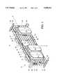
- FIG. 1is a perspective view of the front of a mounting enclosure in accordance with the invention showing a horizontal enclosure mounting arrangement
- FIG. 2is a perspective view of the rear of the mounting enclosure of FIG. 1;
- FIG. 3is a top view of the mounting enclosure of FIG. 1;
- FIG. 4is an end view of the mounting enclosure of FIG. 1;
- FIG. 5ais a front view of the enclosure showing a horizontal enclosure mounting arrangement
- FIG. 5bis a rear view of the enclosure of FIG. 5a;
- FIG. 6ais a front view of the enclosure showing a vertical enclosure mounting arrangement
- FIG. 6bis a rear view of the enclosure of FIG. 6a;
- FIG. 7is a front view of the enclosure according to the invention with the antennas removed;
- FIG. 8ais a bottom view of antenna showing a base plate
- FIG. 8bis an end view of the antenna of FIG. 8a;
- FIG. 8cis a side view of the antenna of FIG. 8a;
- FIG. 9is a section view of the enclosure showing the connections of the antennas with a printed circuit board mounted therein;
- FIG. 10ais a top view of a connector access seal
- FIG. 10bis a side view of the connector access seal of FIG. 10a.
- FIG. 1 and FIG. 2An antenna mounting enclosure 10 according to the invention is illustrated in perspective view in FIG. 1 and FIG. 2.
- the FIGS. 1 and 2show a mounting arrangement for receive antennas 22, 24 and transmit antennas 26 for a horizontal enclosure orientation.
- An alternative vertical enclosure orientationis described and illustrated below in connection with FIG. 6a and 6b.
- the mounting enclosure 10includes a front shell 30 and a rear shell 32 fastened together to enclose an interior space (shown in the sectional view of FIG. 9).
- the mounting enclosure 10is preferably rectangularly shaped and has a longitudinal axis A--A which is longer than a transverse axis B--B.
- the mounting enclosure 10may be mounted, for example, in a horizontal orientation on a cable or strand carried by a pole, or in a vertical orientation mounted to a utility pole or other structure.
- Fastening holes 16are formed in the enclosure 10 for attaching a mounting bracket (not illustrated) to the enclosure 10.
- Local government regulationsmay restrict the space available on a utility pole to a maximum vertical distance.
- the width of the enclosure on the transverse axis B--Bis given a size to comply with the maximum allowable distance, to permit horizontal mounting of the enclosure within allowable limits.
- the antennas 22, 24, and 26each have an antenna axis, indicated by the broken line C, which corresponds in the illustrated antennas to the longer dimension of the antenna unit.
- the antenna axis Cmust be vertically oriented when the enclosure 10 is mounted. As shown in the horizontal enclosure orientation of FIGS. 1 and 2, the antenna axes are parallel to the transverse axis B--B of the enclosure 10. As is further described below, the enclosure 10 according to the invention provides for mounting of the antennas in the correct vertical antenna axis orientation for either enclosure orientation.
- the enclosure 10is preferably formed of aluminum, by casting or machining, to provide an enclosure that is light-weight, strong, and protective from environmental contaminates such as water or moisture.
- Aluminumis heat conductive, which facilitates removing heat from the system's electronic components. Other materials that provide suitable protection and heat conduction may alternatively be employed.
- the shells 30, 32are formed with grooves ridges on their mating edges (not illustrated), and a gasket is provided to seal the edges and prevent the ingress of water or moisture.
- the enclosure 10includes, on both the front 30 and rear 32 shells, a plurality of cooling fins 40.
- the cooling fins 40are rib-like formations that project perpendicularly from the walls of the front 30 and rear 32 shells.
- the fins 40are oriented obliquely to the longitudinal A--A and transverse B--B axes.
- the fins 40are provided to help dissipate heat generated by the printed circuit board and power supply.
- the oblique orientationpreferably at 45° to the longitudinal axis A--A, ensures a flow of air over the cooling fins 40 in either of the horizontal or vertical enclosure orientations.
- the rear shell 32includes connector taps 44, 46 to connect, for example, with a power source and/or a cable connection with a customer in a cable cell system.
- the enclosure 10also includes a sliding door 50 covering an aperture on the front shell 30 to permit field access to the interior of the enclosure without the necessity of removing the enclosure from its mounting and disassembling the shells.
- the door 50is formed as a flat panel with legs 52 extending from each of the four corners. The door 50 is captured between two pins 54 for sliding movement, the legs 52 providing stops to limit movement of the door.
- Supporting feet 60are formed on the front shell 30 and supporting feet 62 are formed on the rear shell 32.
- the feet 60, 62form platforms that allow the enclosure 10 to stand horizontally on the long side, as shown, or as may be understood, vertically on the short side.
- the feet 60, 62are made sufficiently long to accommodate the thickness of the antennas 22, 24, and 26, to allow the enclosure 10 to stand on either the front shell 30 or the rear shell 32 without risk of damage to the antennas.
- the feet 60, 62 shown in the figuresare formed as curved projections at the comers of the shells 30, 32. Alternatively, the feet may be formed as enlargements of the comer cooling fins of the shells 30, 32.
- FIGS. 5a and 5billustrate a front and rear view of the enclosure 10 with horizontal mounting orientation.
- the antennas 22, 24 and 26are, as explained above, oriented with the respective axes C aligned on the transverse axis B--B of the enclosure 10.
- FIGS. 6a and 6billustrate the enclosure 10 in vertical mounting orientation with the antennas 22, 24 and 26 correspondingly oriented on the longitudinal axis A--A of the enclosure 10.
- the transmit antennas 26are separated from the receive antennas 22, 24 by a predetermined space. As described above, the spacing is provided to prevent interference between transmit and receive antennas.
- the respective transmit antennas 26 and receive antennas 22, 24 on each of the front 30 and rear 32 shellsare arranged back to back across that enclosure, that is, in opposition across the interior space. This also helps insure that the various antennas do not interfere with each other.
- a cross section of the enclosure 10shows antennas 24 and 26 connected to the printed circuit board 90 with connectors 92.
- the connectors 92are standard type coaxial connectors with spacers or adapters to provide any needed length.
- the printed circuit board 90is mounted on studs 94 in the rear shell 32.
- the printed circuit board 90is not rigidly attached to the studs 94, but is allowed some float to compensate for expansion and contraction of the connectors 92 due to heating and cooling during use.
- FIG. 7illustrates a front view of the front shell 30 with the antennas removed.
- the antennasare mounted to the enclosure with fasteners (not shown) screwed into a selected one of groups of threaded bosses 72a-b, 74a-b, and 70e-f formed on each of the shells.
- the following description of mounting and connecting means for the antennas for the front shell 30is understood to apply as well to the rear shell 32.
- the groups of bosses 72a-b, 74a-b, and 70e-fare disposed on the shell face each in relation to one of the access holes 82, 84 and 80 to permit each of the antennas to connect with the printed circuit board in the enclosure 10.
- each group of bosses 72a-b, 74a-b, and 70e-fare arranged to define a specific mounting location for a particular receive 22, 24 or transmit antenna 26.
- each group of bossesdefines mounting locations for selectively mounting an antenna in either the horizontal or vertical enclosure mounting orientation.
- the individual bossesare formed in the cooling fins 40, which creates virtually no disruption of cooling air flow between the fins, and simplifies the manufacture of the shell.
- an antenna mounting location for the antenna 22is defined.
- the bosses 72adefine a mounting location for horizontal enclosure mounting orientation
- the bosses 72bdefine a mounting location for vertical enclosure mounting orientation.
- the bosses 72a and the bosses 72bboth have the same positional relationship with the connector access hole 82.
- the boss 72abis used in both orientations and helps simplify the design of the shell face.
- the groups of bosses 74a, 74b and 70e, 70fare similarly disposed to define horizontal and vertical orientation mounting locations at the access holes 84 and 80, respectively.
- the access holes 82 and 84are formed on a first collar 88 and the access hole 80 is formed on a second collar 89, spaced from the first collar 88.
- receive antennaThere are two types of receive antenna, which are unique and not interchangeable. Of course, the receive and transmit antennas are also not interchangeable.
- the collars 88 and 89include mating means to ensure that only the correct type of antenna is mounted at the designated mounting location. According to the preferred embodiment, groups of keying holes 73, 75 and 77 are arranged on the collars for mating with corresponding keying pins provided on the antennas. Each of the groups of keying holes 73, 75, and 77 is arranged in a different pattern. The collar 88, 89 surfaces, therefore, will reject an antenna with an incompatible pin arrangement, thus ensuring exclusive mounting of the designated antenna.
- FIGS. 8a, 8b, and 8cillustrate an antenna 22 in three views.
- the antenna 22includes a base plate 102 and a cover 104.
- the base plate 102carries keying pins 106a, b and the connector 94.
- the connector 94is located at the same base plate position in all the antennas. As seen in FIGS. 80b and 8c, the pins 106 and connector 94 extend from the base plate 102 to engage the keying holes and the connector access holes in the enclosure 10.
- Each keying pin groupcomprises two pins 106 positioned relative to the connector 94.
- One pin 106ais positioned to define with the connector 94 a first line perpendicular to the edge 108 of the base plate adjacent to the connector 94. This pin position 106a is the same for all antennas, which simplifies manufacture.
- the second pin 106bis positioned at a predetermined distance from the connector 94 and to define with the connector 94 a second line at a predetermined angle ⁇ from the first line.
- the relative position of the second pinis unique, which may include the distance from the connector and the angle at which the defined line is disposed.
- the corresponding key holes in the collar 88 of the enclosure 10are positioned with a compatible relationship to the access hole 82. As may be seen in FIG. 7, two sets of keying holes are provided at each of the access holes 82, 84 and 80. The two sets are identically arranged, with one set positioned for each of the vertical and horizontal enclosure mounting orientations.
- a single base plate 102 having holes for all of the alternative antenna pin arrangementsmay be made, and the plate for a particular antenna completed by placing the second pin in the appropriate hole.
- the keying meansmay be formed by other than the described key holes and pins, for example, by using uniquely or differently shaped pins, or other suitable rejection arrangements.
- FIGS. 10a and 10billustrate a sealing grommet 110 that is press fit in each of the access holes 82, 84, and 80 to prevent water or moisture from entering the interior space of the enclosure 10.
- the grommet 110includes a central hole 112 through which the connector 94 is inserted.
- the grommet 110is formed from an elastomeric material, and resiliently abuts the base plate 102 of the antennas to help form a seal.
- the grommets 110readily adapt to small differences in connector length arising from manufacturing tolerances.
Landscapes
- Details Of Aerials (AREA)
- Structure Of Receivers (AREA)
- Support Of Aerials (AREA)
Abstract
Description
Claims (26)
Priority Applications (4)
| Application Number | Priority Date | Filing Date | Title |
|---|---|---|---|
| US08/691,457US5898412A (en) | 1996-08-02 | 1996-08-02 | Transmit/receive antenna mounting enclosure |
| PCT/US1997/012915WO1998006146A1 (en) | 1996-08-02 | 1997-07-25 | Transmit/receive antenna mounting enclosure |
| AU39628/97AAU3962897A (en) | 1996-08-02 | 1997-07-25 | Transmit/receive antenna mounting enclosure |
| ARP970103494AAR008144A1 (en) | 1996-08-02 | 1997-08-01 | MOUNTING CABINET FOR TRANSMISSION / RECEPTION ANTENNA. |
Applications Claiming Priority (1)
| Application Number | Priority Date | Filing Date | Title |
|---|---|---|---|
| US08/691,457US5898412A (en) | 1996-08-02 | 1996-08-02 | Transmit/receive antenna mounting enclosure |
Publications (1)
| Publication Number | Publication Date |
|---|---|
| US5898412Atrue US5898412A (en) | 1999-04-27 |
Family
ID=24776606
Family Applications (1)
| Application Number | Title | Priority Date | Filing Date |
|---|---|---|---|
| US08/691,457Expired - LifetimeUS5898412A (en) | 1996-08-02 | 1996-08-02 | Transmit/receive antenna mounting enclosure |
Country Status (4)
| Country | Link |
|---|---|
| US (1) | US5898412A (en) |
| AR (1) | AR008144A1 (en) |
| AU (1) | AU3962897A (en) |
| WO (1) | WO1998006146A1 (en) |
Cited By (18)
| Publication number | Priority date | Publication date | Assignee | Title |
|---|---|---|---|---|
| US6222503B1 (en)* | 1997-01-10 | 2001-04-24 | William Gietema | System and method of integrating and concealing antennas, antenna subsystems and communications subsystems |
| EP1291960A3 (en)* | 2001-08-28 | 2004-01-07 | Kabushiki Kaisha Toshiba | Antenna with heat sink |
| USD568841S1 (en)* | 2006-12-21 | 2008-05-13 | Adc Telecommunications, Inc. | Enclosure for electronic components |
| US20080252547A1 (en)* | 2007-04-12 | 2008-10-16 | General Instrument Corporation | Mechanically Integrated Cable Mesh Antenna System |
| US20080291627A1 (en)* | 2007-05-23 | 2008-11-27 | Adc Telecommunications, Inc. | Apparatus for enclosing electronic components used in telecommunication systems |
| US20100079344A1 (en)* | 2008-09-26 | 2010-04-01 | General Instrument Corporation | Equipment Housing with Integral Antenna |
| EP3696908A1 (en)* | 2019-02-18 | 2020-08-19 | Nokia Shanghai Bell Co., Ltd. | Mounting device for an active electronic module |
| DE102020207574B3 (en) | 2020-06-18 | 2021-09-09 | Continental Automotive Gmbh | Antenna module |
| US11336004B2 (en) | 2016-02-12 | 2022-05-17 | Mueller International, Llc | Nozzle cap multi-band antenna assembly |
| US11342656B2 (en)* | 2018-12-28 | 2022-05-24 | Mueller International, Llc | Nozzle cap encapsulated antenna system |
| US11422054B2 (en) | 2018-09-04 | 2022-08-23 | Mueller International, Llc | Hydrant cap leak detector with oriented sensor |
| US11469494B2 (en) | 2016-02-12 | 2022-10-11 | Mueller International, Llc | Nozzle cap multi-band antenna assembly |
| US11473993B2 (en) | 2019-05-31 | 2022-10-18 | Mueller International, Llc | Hydrant nozzle cap |
| US11542690B2 (en) | 2020-05-14 | 2023-01-03 | Mueller International, Llc | Hydrant nozzle cap adapter |
| US11590376B2 (en) | 2010-06-16 | 2023-02-28 | Mueller International, Llc | Infrastructure monitoring devices, systems, and methods |
| US11630021B2 (en) | 2011-08-12 | 2023-04-18 | Mueller International, Llc | Enclosure for leak detector |
| EP3993156A4 (en)* | 2019-06-28 | 2023-07-19 | KMW Inc. | ANTENNA DEVICE |
| EP4340121A4 (en)* | 2021-05-14 | 2025-05-07 | KMW Inc. | ANTENNA DEVICE |
Families Citing this family (1)
| Publication number | Priority date | Publication date | Assignee | Title |
|---|---|---|---|---|
| BRPI0922223A8 (en) | 2008-12-02 | 2018-02-06 | Andrew Llc | ANTENNA WASTE FINDS |
Citations (19)
| Publication number | Priority date | Publication date | Assignee | Title |
|---|---|---|---|---|
| DE7710601U1 (en)* | 1977-04-02 | 1977-09-29 | Karl Stolle, Kabel- Und Antennenfabrik, 4670 Luenen | TV ANTENNA |
| GB1530551A (en)* | 1976-04-26 | 1978-11-01 | Siemens Ag | Antenna arrangements |
| USD252568S (en) | 1977-06-22 | 1979-08-07 | Comstock Wilford K | Housing for electrical circuits |
| GB2070178A (en)* | 1979-12-22 | 1981-09-03 | Bosch Gmbh Robert | A method of securing first and second components against relative displacement and an assembly of first and second components produced thereby |
| USD265986S (en) | 1980-01-30 | 1982-08-31 | Reliance Electric Company | Electronic enclosure cover |
| USD266662S (en) | 1980-04-14 | 1982-10-26 | Akzona Incorporated | Electrical cable splice enclosure |
| US4403106A (en)* | 1981-09-21 | 1983-09-06 | Northern Telecom Limited | Terminal enclosure for cable stubs, with variable entry positions |
| US4419537A (en)* | 1982-03-17 | 1983-12-06 | Gte Products Corporation | Electrical wiring box arrangements |
| US4661821A (en)* | 1985-03-15 | 1987-04-28 | General Electric Company | Vandalism-resistant UHF antenna |
| EP0395493A1 (en)* | 1989-04-27 | 1990-10-31 | Joseph Mellina | Attachment device for rigid or semi-rigid plates |
| USD312244S (en) | 1988-03-28 | 1990-11-20 | Keptel, Inc. | Enclosure for an electrical protector and terminal block |
| US5019829A (en)* | 1989-02-08 | 1991-05-28 | Heckman Douglas E | Plug-in package for microwave integrated circuit having cover-mounted antenna |
| USD317908S (en) | 1988-03-31 | 1991-07-02 | Channell William H | All weather covering for cable television equipment |
| US5132648A (en)* | 1990-06-08 | 1992-07-21 | Rockwell International Corporation | Large array MMIC feedthrough |
| USD336074S (en) | 1989-03-23 | 1993-06-01 | North American Philips Corporation | Housing for cable television equipment |
| US5276455A (en)* | 1991-05-24 | 1994-01-04 | The Boeing Company | Packaging architecture for phased arrays |
| US5423072A (en)* | 1992-07-15 | 1995-06-06 | Nec Corporation | Testing transmitter-receiver apparatus for sector cell base station |
| US5459474A (en)* | 1994-03-22 | 1995-10-17 | Martin Marietta Corporation | Active array antenna radar structure |
| US5619217A (en)* | 1995-05-19 | 1997-04-08 | Allen Telecom Group, Inc. | Cellular and PCS antenna mounting assembly |
- 1996
- 1996-08-02USUS08/691,457patent/US5898412A/ennot_activeExpired - Lifetime
- 1997
- 1997-07-25AUAU39628/97Apatent/AU3962897A/ennot_activeAbandoned
- 1997-07-25WOPCT/US1997/012915patent/WO1998006146A1/enactiveApplication Filing
- 1997-08-01ARARP970103494Apatent/AR008144A1/enunknown
Patent Citations (19)
| Publication number | Priority date | Publication date | Assignee | Title |
|---|---|---|---|---|
| GB1530551A (en)* | 1976-04-26 | 1978-11-01 | Siemens Ag | Antenna arrangements |
| DE7710601U1 (en)* | 1977-04-02 | 1977-09-29 | Karl Stolle, Kabel- Und Antennenfabrik, 4670 Luenen | TV ANTENNA |
| USD252568S (en) | 1977-06-22 | 1979-08-07 | Comstock Wilford K | Housing for electrical circuits |
| GB2070178A (en)* | 1979-12-22 | 1981-09-03 | Bosch Gmbh Robert | A method of securing first and second components against relative displacement and an assembly of first and second components produced thereby |
| USD265986S (en) | 1980-01-30 | 1982-08-31 | Reliance Electric Company | Electronic enclosure cover |
| USD266662S (en) | 1980-04-14 | 1982-10-26 | Akzona Incorporated | Electrical cable splice enclosure |
| US4403106A (en)* | 1981-09-21 | 1983-09-06 | Northern Telecom Limited | Terminal enclosure for cable stubs, with variable entry positions |
| US4419537A (en)* | 1982-03-17 | 1983-12-06 | Gte Products Corporation | Electrical wiring box arrangements |
| US4661821A (en)* | 1985-03-15 | 1987-04-28 | General Electric Company | Vandalism-resistant UHF antenna |
| USD312244S (en) | 1988-03-28 | 1990-11-20 | Keptel, Inc. | Enclosure for an electrical protector and terminal block |
| USD317908S (en) | 1988-03-31 | 1991-07-02 | Channell William H | All weather covering for cable television equipment |
| US5019829A (en)* | 1989-02-08 | 1991-05-28 | Heckman Douglas E | Plug-in package for microwave integrated circuit having cover-mounted antenna |
| USD336074S (en) | 1989-03-23 | 1993-06-01 | North American Philips Corporation | Housing for cable television equipment |
| EP0395493A1 (en)* | 1989-04-27 | 1990-10-31 | Joseph Mellina | Attachment device for rigid or semi-rigid plates |
| US5132648A (en)* | 1990-06-08 | 1992-07-21 | Rockwell International Corporation | Large array MMIC feedthrough |
| US5276455A (en)* | 1991-05-24 | 1994-01-04 | The Boeing Company | Packaging architecture for phased arrays |
| US5423072A (en)* | 1992-07-15 | 1995-06-06 | Nec Corporation | Testing transmitter-receiver apparatus for sector cell base station |
| US5459474A (en)* | 1994-03-22 | 1995-10-17 | Martin Marietta Corporation | Active array antenna radar structure |
| US5619217A (en)* | 1995-05-19 | 1997-04-08 | Allen Telecom Group, Inc. | Cellular and PCS antenna mounting assembly |
Cited By (31)
| Publication number | Priority date | Publication date | Assignee | Title |
|---|---|---|---|---|
| US6222503B1 (en)* | 1997-01-10 | 2001-04-24 | William Gietema | System and method of integrating and concealing antennas, antenna subsystems and communications subsystems |
| EP1291960A3 (en)* | 2001-08-28 | 2004-01-07 | Kabushiki Kaisha Toshiba | Antenna with heat sink |
| USD568841S1 (en)* | 2006-12-21 | 2008-05-13 | Adc Telecommunications, Inc. | Enclosure for electronic components |
| US20080252547A1 (en)* | 2007-04-12 | 2008-10-16 | General Instrument Corporation | Mechanically Integrated Cable Mesh Antenna System |
| US7973721B2 (en)* | 2007-04-12 | 2011-07-05 | General Instrument Corporation | Mechanically integrated cable mesh antenna system |
| US20080291627A1 (en)* | 2007-05-23 | 2008-11-27 | Adc Telecommunications, Inc. | Apparatus for enclosing electronic components used in telecommunication systems |
| US7535716B2 (en)* | 2007-05-23 | 2009-05-19 | Adc Telecommunications, Inc. | Apparatus for enclosing electronic components used in telecommunication systems |
| US20100079344A1 (en)* | 2008-09-26 | 2010-04-01 | General Instrument Corporation | Equipment Housing with Integral Antenna |
| US8106837B2 (en)* | 2008-09-26 | 2012-01-31 | General Instrument Corporation | Equipment housing with integral antenna |
| US11590376B2 (en) | 2010-06-16 | 2023-02-28 | Mueller International, Llc | Infrastructure monitoring devices, systems, and methods |
| US11680865B2 (en) | 2011-08-12 | 2023-06-20 | Mueller International, Llc | Leak detection in water distribution systems using acoustic signals |
| US11630021B2 (en) | 2011-08-12 | 2023-04-18 | Mueller International, Llc | Enclosure for leak detector |
| US11469494B2 (en) | 2016-02-12 | 2022-10-11 | Mueller International, Llc | Nozzle cap multi-band antenna assembly |
| US11837782B2 (en) | 2016-02-12 | 2023-12-05 | Mueller International, Llc | Nozzle cap assembly |
| US12212053B2 (en) | 2016-02-12 | 2025-01-28 | Mueller International, Llc | Nozzle cap multi-band antenna assembly |
| US11652284B2 (en) | 2016-02-12 | 2023-05-16 | Mueller International, Llc | Nozzle cap assembly |
| US11527821B2 (en) | 2016-02-12 | 2022-12-13 | Mueller International, Llc | Nozzle cap assembly |
| US11336004B2 (en) | 2016-02-12 | 2022-05-17 | Mueller International, Llc | Nozzle cap multi-band antenna assembly |
| US11422054B2 (en) | 2018-09-04 | 2022-08-23 | Mueller International, Llc | Hydrant cap leak detector with oriented sensor |
| US11692901B2 (en) | 2018-09-04 | 2023-07-04 | Mueller International, Llc | Hydrant cap leak detector with oriented sensor |
| US11342656B2 (en)* | 2018-12-28 | 2022-05-24 | Mueller International, Llc | Nozzle cap encapsulated antenna system |
| EP3696908A1 (en)* | 2019-02-18 | 2020-08-19 | Nokia Shanghai Bell Co., Ltd. | Mounting device for an active electronic module |
| US12078572B2 (en) | 2019-05-31 | 2024-09-03 | Mueller International, Llc | Hydrant nozzle cap |
| US11473993B2 (en) | 2019-05-31 | 2022-10-18 | Mueller International, Llc | Hydrant nozzle cap |
| US11624674B2 (en) | 2019-05-31 | 2023-04-11 | Mueller International, Llc | Hydrant nozzle cap with antenna |
| EP3993156A4 (en)* | 2019-06-28 | 2023-07-19 | KMW Inc. | ANTENNA DEVICE |
| US11888207B2 (en) | 2019-06-28 | 2024-01-30 | Kmw Inc. | Antenna apparatus |
| US11542690B2 (en) | 2020-05-14 | 2023-01-03 | Mueller International, Llc | Hydrant nozzle cap adapter |
| US12084844B2 (en) | 2020-05-14 | 2024-09-10 | Mueller International, Llc | Hydrant nozzle cap adapter |
| DE102020207574B3 (en) | 2020-06-18 | 2021-09-09 | Continental Automotive Gmbh | Antenna module |
| EP4340121A4 (en)* | 2021-05-14 | 2025-05-07 | KMW Inc. | ANTENNA DEVICE |
Also Published As
| Publication number | Publication date |
|---|---|
| AR008144A1 (en) | 1999-12-09 |
| WO1998006146A1 (en) | 1998-02-12 |
| AU3962897A (en) | 1998-02-25 |
Similar Documents
| Publication | Publication Date | Title |
|---|---|---|
| US5898412A (en) | Transmit/receive antenna mounting enclosure | |
| US5111362A (en) | Enclosure assembly with two identical covers having modifiable supports for asymmetrically housing a printed circuit board or the like | |
| US5827074A (en) | End mounting terminator for backplanes | |
| US6369320B1 (en) | Enclosure structure for electronic equipment | |
| US5402322A (en) | Modular wall-mounted equipment enclosure | |
| US5385488A (en) | Patch panel | |
| US5880932A (en) | Modular power supply | |
| US11825625B2 (en) | Housing for aligning power supply components in a power supply system | |
| US6646197B1 (en) | High performance EMI shield for electronic equipment | |
| CN110610666A (en) | Flexible Display Mounting Device and Display Device | |
| CN216287383U (en) | Module drain pan and display screen | |
| US5761042A (en) | Radio frequency compatible multi-board cluster | |
| CN216647759U (en) | LED display screen convenient to maintenance | |
| CN214891755U (en) | Electric Control Box Components and Air Conditioners | |
| CN222884142U (en) | Distribution box | |
| CA2364013A1 (en) | Power distribution panel with flame containment slots | |
| US5181168A (en) | Accommodation device for assembly units | |
| CN222582855U (en) | A vehicle-mounted integrated electromagnetic shielding chassis | |
| KR20220057977A (en) | a case with a subrack | |
| GB2288693A (en) | Outdoor communication device | |
| CN222509845U (en) | Vehicle-mounted integrated electromagnetic shielding case | |
| CN219919492U (en) | Network optimizing device | |
| HUT69825A (en) | Modular house for telecommunication devices | |
| CN218415446U (en) | Box structure convenient to loading and unloading | |
| CN216805288U (en) | Car panorama camera mounting structure and car |
Legal Events
| Date | Code | Title | Description |
|---|---|---|---|
| AS | Assignment | Owner name:ERICSSON, INC., NORTH CAROLINA Free format text:ASSIGNMENT OF ASSIGNORS INTEREST;ASSIGNORS:JONES, CLIFFORD T.;RUCKDESCHEL, THOMAS;REEL/FRAME:008155/0906 Effective date:19960731 | |
| STCF | Information on status: patent grant | Free format text:PATENTED CASE | |
| FPAY | Fee payment | Year of fee payment:4 | |
| FPAY | Fee payment | Year of fee payment:8 | |
| FPAY | Fee payment | Year of fee payment:12 | |
| AS | Assignment | Owner name:CLUSTER LLC, DELAWARE Free format text:ASSIGNMENT OF ASSIGNORS INTEREST;ASSIGNOR:ERICSSON INC.;REEL/FRAME:030192/0273 Effective date:20130211 | |
| AS | Assignment | Owner name:UNWIRED PLANET, LLC, NEVADA Free format text:ASSIGNMENT OF ASSIGNORS INTEREST;ASSIGNOR:CLUSTER LLC;REEL/FRAME:030201/0389 Effective date:20130213 | |
| AS | Assignment | Owner name:CLUSTER LLC, SWEDEN Free format text:NOTICE OF GRANT OF SECURITY INTEREST IN PATENTS;ASSIGNOR:UNWIRED PLANET, LLC;REEL/FRAME:030369/0601 Effective date:20130213 |