US5897574A - Suture anchor inserter assembly and method - Google Patents
Suture anchor inserter assembly and methodDownload PDFInfo
- Publication number
- US5897574A US5897574AUS09/111,079US11107998AUS5897574AUS 5897574 AUS5897574 AUS 5897574AUS 11107998 AUS11107998 AUS 11107998AUS 5897574 AUS5897574 AUS 5897574A
- Authority
- US
- United States
- Prior art keywords
- handle
- anchor
- set forth
- relative
- outer member
- Prior art date
- Legal status (The legal status is an assumption and is not a legal conclusion. Google has not performed a legal analysis and makes no representation as to the accuracy of the status listed.)
- Expired - Lifetime
Links
- 238000000034methodMethods0.000titleclaimsdescription29
- 238000003780insertionMethods0.000claimsdescription28
- 230000037431insertionEffects0.000claimsdescription28
- 230000000694effectsEffects0.000claims2
- 230000000903blocking effectEffects0.000claims1
- 210000001519tissueAnatomy0.000description98
- 210000003811fingerAnatomy0.000description18
- 210000000988bone and boneAnatomy0.000description15
- 238000010276constructionMethods0.000description9
- 210000003813thumbAnatomy0.000description9
- 239000000463materialSubstances0.000description4
- 230000000994depressogenic effectEffects0.000description3
- 230000000712assemblyEffects0.000description2
- 238000000429assemblyMethods0.000description2
- 229910001220stainless steelInorganic materials0.000description2
- 239000010935stainless steelSubstances0.000description2
- 210000002435tendonAnatomy0.000description2
- 206010043268TensionDiseases0.000description1
- 238000004873anchoringMethods0.000description1
- 230000015572biosynthetic processEffects0.000description1
- 230000003247decreasing effectEffects0.000description1
- 210000004936left thumbAnatomy0.000description1
- 238000012544monitoring processMethods0.000description1
- 230000000717retained effectEffects0.000description1
- 210000004872soft tissueAnatomy0.000description1
- 230000000007visual effectEffects0.000description1
Images


Classifications
- A—HUMAN NECESSITIES
- A61—MEDICAL OR VETERINARY SCIENCE; HYGIENE
- A61B—DIAGNOSIS; SURGERY; IDENTIFICATION
- A61B17/00—Surgical instruments, devices or methods
- A61B17/04—Surgical instruments, devices or methods for suturing wounds; Holders or packages for needles or suture materials
- A61B17/0401—Suture anchors, buttons or pledgets, i.e. means for attaching sutures to bone, cartilage or soft tissue; Instruments for applying or removing suture anchors
- A—HUMAN NECESSITIES
- A61—MEDICAL OR VETERINARY SCIENCE; HYGIENE
- A61B—DIAGNOSIS; SURGERY; IDENTIFICATION
- A61B17/00—Surgical instruments, devices or methods
- A61B17/04—Surgical instruments, devices or methods for suturing wounds; Holders or packages for needles or suture materials
- A61B17/0493—Protective devices for suturing, i.e. for protecting the patient's organs or the operator
- A—HUMAN NECESSITIES
- A61—MEDICAL OR VETERINARY SCIENCE; HYGIENE
- A61B—DIAGNOSIS; SURGERY; IDENTIFICATION
- A61B17/00—Surgical instruments, devices or methods
- A61B17/04—Surgical instruments, devices or methods for suturing wounds; Holders or packages for needles or suture materials
- A61B17/0401—Suture anchors, buttons or pledgets, i.e. means for attaching sutures to bone, cartilage or soft tissue; Instruments for applying or removing suture anchors
- A61B2017/0409—Instruments for applying suture anchors
- A—HUMAN NECESSITIES
- A61—MEDICAL OR VETERINARY SCIENCE; HYGIENE
- A61B—DIAGNOSIS; SURGERY; IDENTIFICATION
- A61B17/00—Surgical instruments, devices or methods
- A61B17/04—Surgical instruments, devices or methods for suturing wounds; Holders or packages for needles or suture materials
- A61B2017/0496—Surgical instruments, devices or methods for suturing wounds; Holders or packages for needles or suture materials for tensioning sutures
- A—HUMAN NECESSITIES
- A61—MEDICAL OR VETERINARY SCIENCE; HYGIENE
- A61B—DIAGNOSIS; SURGERY; IDENTIFICATION
- A61B17/00—Surgical instruments, devices or methods
- A61B17/28—Surgical forceps
- A61B17/29—Forceps for use in minimally invasive surgery
- A61B2017/2901—Details of shaft
- A61B2017/2905—Details of shaft flexible
Definitions
- the present inventionrelates to an improved suture anchor inserter assembly and method of using the suture anchor inserter assembly to position a suture anchor in either soft or hard body tissue.
- suture anchor inserter assembliesto position suture anchors in either soft body tissue or hard body tissue.
- Suture anchor inserter assemblies for positioning suture anchors in soft or hard body tissueare disclosed in U.S. Pat. Nos. 5,403,348 and 5,464,426.
- the suture anchor inserter assemblybe constructed in such a manner as to facilitate accurate positioning of the suture anchor. Once the suture anchor has been accurately positioned relative to the body tissue, the suture anchor inserter assembly should be easily utilized to move the suture anchor into the body tissue.
- the present inventionrelates to a new and improved suture anchor inserter assembly and method of using the suture anchor inserter assembly.
- the suture anchor inserter assemblyincludes a handle and a shaft which extends outward from the handle.
- the shaftmay have a linear or non-linear configuration.
- a suturemay extend through a passage in the shaft and the handle. The suture may be used to apply force to an anchor to hold the anchor in a chamber at an outer end of the shaft.
- the shaftmay advantageously be formed by relatively movable inner and outer members.
- a retainer assemblymay hold the inner and outer members against relative movement until the anchor has been moved to a desired position relative to body tissue. Moving the anchor to a desired position relative to body tissue may be facilitated by deflecting body tissue with the shaft of the suture anchor inserter assembly.
- the retainer assemblyis manually actuated to release the inner and outer members for relative movement. During this relative movement, the anchor is inserted into either hard or soft body tissue.
- the outer memberis movable relative to the inner member upon operation of the retainer assembly to a release condition. As the outer member is moved relative to the inner member, the outer member is advantageously moved into the handle. To facilitate gripping of the handle, the handle may advantageously have a triangular cross-sectional configuration.
- the suture anchor inserter assemblymay advantageously include a suture anchor insertion depth control assembly. This assembly is operable to limit the distance to which an anchor is inserted into body tissue.
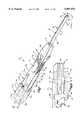
- FIG. 1is a pictorial illustration of a suture anchor inserter assembly constructed in accordance with the present invention
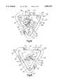
- FIG. 2is an enlarged fragmentary view, taken generally along the line 2--2 of FIG. 1, illustrating the manner in which a suture holds a suture anchor in a chamber formed in a shaft of the suture anchor inserter assembly;
- FIG. 3is an enlarged fragmentary sectional view, taken generally along the line 3--3 of FIG. 1, illustrating the manner in which the shaft extends outward from a handle of the suture anchor inserter assembly;
- FIG. 4is an enlarged view of a portion of FIG. 3 and illustrating a retainer assembly having an actuator member which retains a movable outer member which forms a portion of the shaft, against movement relative to a handle of the suture anchor inserter assembly;
- FIG. 5is a sectional view, taken generally along the line 5--5 of FIG. 4, further illustrating construction of the retainer assembly
- FIG. 6is an enlarged view of a portion of FIG. 5;
- FIG. 7is a fragmentary sectional view, generally similar to FIG. 3 but on a reduced scale, illustrating the suture anchor inserter assembly when the actuator member has been moved from the engaged position of FIGS. 3-6 to a disengaged position;
- FIG. 8is a sectional view, taken generally along the line 8--8 of FIG. 7, further illustrating the retainer assembly with the actuator member in the disengaged position;
- FIG. 9is a fragmentary sectional view, generally similar to FIG. 7, illustrating the relationship between the outer member of the shaft and the handle when the outer member has been moved from the extended position of FIG. 7 to the retracted position of FIG. 9;
- FIG. 10is a sectional view, generally similar to FIG. 8, taken generally along the line 10--10 of FIG. 9;
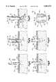
- FIG. 11is a top plan view, taken generally along the line 11--11 of FIG. 5;
- FIG. 12is a side elevational view, taken generally along the line 12--12 of FIG. 11;
- FIG. 13is a side elevational view, taken generally along the line 13--13 of FIG. 11;
- FIG. 14is a proximal end view, taken generally along the line 14--14 of FIG. 1;
- FIG. 15is a distal end view, taken generally along the line 15--15 of FIG. 1;
- FIG. 16is a pictorial illustration of the manner in which the handle of the suture anchor inserter assembly is manually gripped
- FIG. 17is a pictorial illustration of the manner in which force is applied to the handle of the suture anchor inserter assembly to deflect body tissue with the shaft of the suture anchor inserter assembly;
- FIG. 18is a schematic illustration depicting one way in which an opening may be formed in body tissue
- FIG. 19is a schematic illustration depicting the manner in which a suture anchor is positioned relative to the opening of FIG. 18 by the suture anchor inserter assembly of FIG. 1;
- FIG. 20is a schematic illustration depicting the manner in which a suture anchor is moved into body tissue by the suture anchor inserter assembly of FIG. 1;
- FIG. 21is a schematic illustration depicting the manner in which the suture is tensioned to rotate the suture anchor relative to the body tissue;
- FIG. 22is a schematic illustration depicting the manner in which the suture is tensioned to press the suture anchor against body tissue
- FIG. 23is an illustration of a second embodiment of the suture anchor
- FIG. 24is an illustration of a second embodiment of the suture anchor inserter assembly
- FIG. 25is a side elevational view, similar to FIG. 12, of an embodiment of the suture anchor inserter assembly having an anchor insertion depth control assembly;
- FIG. 26is a side elevational view, similar to FIGS. 12 and 25, of an embodiment of the suture anchor inserter assembly having a non-linear shaft.
- FIG. 1A suture anchor inserter assembly 30 constructed and used in accordance with the present invention is illustrated in FIG. 1.
- the suture anchor inserter assembly 30includes a manually engageable handle 32 and a shaft 34 which extends axially outward from the handle.
- An outer or distal end portion 36 (FIG. 2) of the shaft 34has a chamber 38 in which a suture anchor 40 is received.
- a suture 42is affective to apply force against the anchor 40 to retain the anchor in the chamber 38.
- the illustrated anchor 40has a cylindrical tubular side wall 46. A trailing end portion 48 of the anchor 40 is received in the cylindrical chamber 38. It should be understood that the anchor 40 could have a construction different than the construction shown in FIG. 2. For example, the anchor 40 could have a polygonal cross sectional configuration if desired. Although it is preferred to form the anchor 40 of stainless steel, the anchor could be formed of biodegradable material or body tissue if desired.
- a leading end portion 50 (FIG. 2) of the anchor 40extends axially outward from the shaft 34.
- the anchor 40can be used to retain the suture 42 in either hard body tissue, such as bone, or soft body tissue, such as skin.
- the handle 32has a generally triangular cross-sectional configuration (FIGS. 1, 5, 14 and 15).
- the triangular cross-sectional configuration of the handle 32facilitates comfortable gripping of the handle by a surgeon.
- the triangular cross-sectional configuration of the handle 32facilitates accurate pointing of the shaft 34 and accurate positioning of the anchor 40 by the surgeon.
- a first side 56 (FIGS. 1 and 11) of the handle 32is engaged by the first finger on the right hand of the surgeon.
- a second side 58 (FIGS. 1 and 12) of the handle 32is engaged by the second finger on the right hand of the surgeon.
- a third side 60 (FIGS. 1 and 13)is engaged by the thumb on the right hand of the surgeon. The thumb and first two fingers on the right hand of the surgeon cooperate to grip the handle in much the same manner as in which a pencil is gripped.
- the first finger on the left hand of the surgeonwould engage the first side 56 of the handle 32 (FIGS. 11 and 16), the same as with a right handed grip.
- the second finger of the surgeonwould engage the third side 60 (FIG. 13) of the handle 32.
- the left thumb of the surgeonwould engage the second side 58 of the handle 32 (FIGS. 12, 16 and 17).
- the triangular cross-sectional configuration of the handle 32enables the suture anchor inserter assembly 30 to be easily gripped with either hand.
- the triangular cross-sectional configuration of the handle 32results in offsetting forces being applied against the three sides 56, 58 and 60 of the handle. These offsetting forces are directed inward toward a longitudinal central axis of the handle. This results in the handle 32 being relatively stable in the hand of the surgeon when it is gripped by the surgeon.
- the shaft 34is formed by tubular inner and outer members 66 and 68 (FIGS. 2 and 3) which are relatively movable.
- the tubular inner member 66has a cylindrical central passage 70 which is axially aligned with a cylindrical central passage 72 (FIG. 3) through the handle 32.
- the suture 42extends through the passage 70 in the inner member 66 and through the passage 72 in the handle 32.
- the passages 70 and 72 through the shaft 34 and handle 32have longitudinal central axes which are coincident with the longitudinal central axis of the handle 32. It should be understood that the inner and outer members 66 and 68 and passages 70 and 72 could have a configuration which is different than the illustrated cylindrical configuration.
- the tubular inner member 66has an inner end portion 76 (FIG. 1) which is fixedly connected with the handle 32.
- the connection between the inner end portion 76 of the tubular inner member 66 and the handle 32holds the inner member 66 against movement relative to the handle 32.
- the tubular outer member 68telescopically encloses a portion of the inner member 66.
- the outer member 68cooperates with the inner member 66 to form the cylindrical chamber 38 (FIG. 2) in which the trailing end portion 48 of the anchor 40 is received.
- the outer member 68is axially movable along the inner member between an extended position (FIGS. 1, 2, 3 and 7) and a fully retracted position (FIG. 9).
- an outer end portion 80 (FIG. 2) of the outer member 68extends axially outward of the outer end portion 82 of the inner member 66. This results in the formation of the chamber 38 in the outer end portion 80 of the outer member 68.
- the inner end of the chamber 38is formed by the outer end of the inner member 66.
- the outer member 68is axially movable along the stationary inner member 66 from the extended position of FIGS. 3 and 7 to the fully retracted position of FIG. 9. As the outer member 68 moves from the extended position (FIG. 7) to the fully retracted position (FIG. 9) the outer member 68 is telescopically moved into the handle 32. By sliding the outer member 68 into the handle 32, the overall length of the suture anchor inserter assembly 30 tends to be minimized. If desired, the outer member 68 could be fixedly connected to the handle 32 and the inner member 66 moved relative to the handle.
- the anchor 40is held in the chamber 38 by the suture 42.
- the suture 42has two sections or legs which extend from the anchor 40.
- an outer leg 86 (FIG. 1) of the suture 42extends along the outside of the shaft 34 and into the handle 32.
- An inner leg 88 (FIG. 2) of the suture 42extends through the anchor 40 and through the central passage 70 in the inner member 66.
- the inner leg 88 of the suture 42also extends through the passage 72 (FIG. 3) in the handle 32.
- Tension in the two legs 86 and 88 of the suture 42enables the suture to apply force against the leading end portion 50 of the anchor 40 (FIG. 2). This force presses the trailing end portion 48 of the anchor against the outer end portion 82 of the inner member 66. The force applied against the anchor by the two legs 86 and 88 of the suture 42 retains the anchor 40 in the chamber 38 in the outer end portion 36 of the shaft 34. This enables the suture anchor inserter assembly 30 to be provided to a surgeon as a unit which is ready to be used.
- a retainer assembly 92is manually operable between an engaged condition (FIGS. 3-6) retaining the inner and outer members 66 and 68 against relative movement and a disengaged condition (FIGS. 7-10) in which one of the inner and outer members is movable relative to the other.
- the retainer assembly 92When the retainer assembly 92 is in the engaged condition (FIGS. 3-6) it retains the inner and outer members 66 and 68 against axial movement relative to each other.
- the retainer assembly 92is in the disengaged condition, the retainer assembly is ineffective to retain the inner and outer members 66 and 68 against axial movement relative to each other.
- the retainer assembly 92includes a manually operable actuator member 94 (FIGS. 1 and 3-10).
- the actuator member 94is slidably mounted on the handle 32.
- the actuator member 94is manually movable relative to the handle between the disengaged position of FIGS. 3-6 and the disengaged position of FIGS. 7-10.
- the retainer assembly 92holds the outer member 68 in the extended position shown in FIGS. 1 and 3.
- the actuator member 94is manually moved from the engaged position to the disengaged position of FIGS. 7-10, the retainer assembly 92 is operated to a disengaged condition.
- the retainer assembly 92is in the disengaged condition, the outer member 68 is released for axial movement from the extended position of FIG. 7 to the fully retracted position of FIG. 9.
- the outer member 68is slidable along the inner member 66 into the handle 32 to the fully retracted position of FIG. 9 when the retainer assembly 92 is in the disengaged condition.
- the retainer assembly 92When a surgeon is using the suture anchor inserter assembly 30 to deflect body tissue and move an anchor 40 to a desired position relative to other body tissue, in the manner illustrated schematically in FIG. 17, the retainer assembly 92 is maintained in the engaged condition. At this time, the outer member 68 is held against axial movement relative to the handle 32. The suture 42 holds the trailing end portion 48 (FIG. 2) of the anchor 40 in the chamber 38. However, the leading end portion of the anchor 40 extends from the chamber 38 and the shaft 34 (FIG. 17) to facilitate visual alignment of the leading end portion 50 of the anchor 40 with the body tissue.
- the actuator member 94is manually depressed by the first finger on the hand of the surgeon. This results in the retainer assembly 92 being operated from the engaged condition to the disengaged condition to release the outer member 68 for axial movement relative to the inner member 66 and handle 32. Axial movement of the shaft 34 relative to the body tissue and insertion of the anchor 40 into the body tissue then results in forces being applied by the body tissue against the outer member 68. These forces move the outer member 68 from the extended position of FIG. 7 toward the fully retracted position of FIG. 9 as the anchor 40 is inserted into the body tissue.
- the suture anchor inserter assembly 30may be provided with a suture anchor insertion depth control assembly 372 (FIG. 25).
- the suture anchor insertion depth control assembly 372limits the distance which an anchor is inserted into body tissue. This enables a surgeon to select a desired depth of anchor insertion and to set the suture anchor insertion depth control assembly 372 so that the suture anchor inserter assembly is operable to insert the anchor to the desired depth.
- the various features of the suture anchor inserter assembly 30could be used separately or in various combinations.
- the triangular cross-sectional configuration of the handle 32could be used without the axially movable outer member 68 and the retainer assembly 92.
- the axially movable outer member 68could be used with a handle having a different configuration than the illustrated triangular cross-sectional configuration of the handle 32 and without the retainer assembly 92.
- the retainer assembly 92could be utilized with a shaft having an inner member which moves relative to an outer member.
- the handle 32advantageously has a triangular cross-sectional configuration (FIG. 5).
- the three sides 56, 58 and 60 of the handle 32are all of the same size.
- the included angles between the three sidesall equal to sixty degrees. Therefore, the handle 32 has an equilateral triangular cross sectional configuration.
- the first side 56 (FIG. 11) of the handle 32has a generally rectangular configuration.
- a longitudinal central axis of the first side 56 of the handle 32extends parallel to the longitudinal central axis of the shaft 34.
- the longitudinal central axis of the first side 56 of the handle 32extends perpendicular to and intersects a central axis of the actuator member 94.
- the first side 56 of the handle 32has a flat major side surface 100 (FIG. 11).
- a longitudinally extending recess 102is formed in the major side surface 100.
- the recess 102has a longitudinal central axis which is parallel to the longitudinal central axis of the major side surface 100 of the handle 32.
- the central axis of the recess 102extends perpendicular to and intersects a central axis of the actuator member 94.
- the central axis of the recess 102is parallel to and offset from the central axis of the shaft 34.
- the first side 56 of the handle 32has a pair of parallel corners 106 and 108.
- the corners 106 and 108 of the first side 56 of the handle 32extend parallel to the central axis of the shaft 34.
- the corners 106 and 108extend along the handle 32 between a proximal or inner end surface 110 and a distal or outer end surface 112 of the handle 32.
- the corners 106 and 108taper inward toward each other on an axially tapering distal end portion 116 of the handle 32.
- the axially inward tapering distal end portion 116 of the handlehas a configuration corresponding to the configuration of the frustrum of a tetrahedron.
- a plurality of ribs 120extend across the major side surface 100 of the handle 32.
- the ribs 120extend perpendicular to the corners 106 and 108 of the handle 32 and to the longitudinal central axis of the shaft 34.
- the ribs 120are partially disposed between the recess 102 and the actuator member 94.
- the ribs 120are engageable by the first finger on the hand of a surgeon to minimize any tendency for the finger to slip.
- a recess 124(FIG. 11) is provided in the major side surface 100 to receive an arcuate needle 126 which is connected with an end of the outer leg 86 of the suture 42.
- the recess 124includes a circular portion 128 in which the end of the needle 126 connected with the suture 42 is disposed.
- the recess 124includes an arcuate portion 130 in which the body of the needle 126 is disposed.
- a slide 134(FIG. 1) covers the recess 124 to retain the needle 126 in the recess.
- the slide 134has an equilateral triangular cross-sectional configuration and is axially movable along the handle 32.
- a rectangular side wall 136 on the slideblocks the recess 124 to retain the needle 126 and suture 42 in the recess.
- the slide 134is movable axially along the handle 32 toward the shaft 34, that is, toward the right as viewed in FIG. 1, to an open position.
- the recess 124When the slide 134 is in the open position, the recess 124 is uncovered. When the recess 124 is uncovered, the end of the needle 126 connected with the suture 42 can be manually grasped at the relatively large circular section 128 (FIG. 11) of the recess 124. Once the needle has been removed from the recess 124, the slide may be returned to its closed position over the recess if desired.
- the second side 58 (FIG. 12) of the handle 32has a generally rectangular configuration.
- the second side 58 of the handlehas a longitudinal central axis which is parallel to the longitudinal central axis of the shaft 34 and to the longitudinal central axis of the first side 56 (FIG. 11) of the handle.
- the longitudinal central axis of the second side 58extends perpendicular to and is offset to one side of the central axis of the actuator member 94.
- the second side 58 (FIG. 12) of the handlehas a flat major side surface 140 which extends parallel to the central axis of the shaft 34.
- the major side surface 140extends between the corner 108 and a corner 144.
- the corner 108is formed between the major side surface 140 and the major side surface 100.
- the corners 108 and 144extend parallel to each other and to the longitudinal central axis of the shaft 34.
- a plurality of ribs 146extend across the major side surface 140 (FIG. 12).
- the parallel ribs 156extend perpendicular to the corners 108 and 144.
- the parallel ribsare engageable by the second finger on the right hand of a surgeon or by the thumb on the left hand of a surgeon to retard slippage between the hand of the surgeon and the handle 32.
- Some of the ribs 146 on the second side 58 of the handle 32are aligned with the ribs 120 on the first side 56 (FIG. 11) of the handle 32.
- An elongated recess 150(FIG. 12) is formed in the major side surface 140.
- the recess 150has a longitudinal central axis which extends parallel to the longitudinal central axis of the shaft 34.
- a cylindrical pin or peg 152is disposed at the end of the recess 150 furthest from the proximal end surface 110 of the handle 32.
- the suture 42extends around the pin 152. Although only a single turn of the suture 42 has been shown in FIG. 12 as extending around the pin 152, it is contemplated that a plurality of turns of the suture may extend around the pin. If desired, a second pin or peg could be provided in the recess 150 to facilitate coiling of the suture 42 in the recess.
- the suture 42could be wrapped around the handle in a recess 154.
- the recess 154has a triangular cross-sectional configuration and extends along all three sides 56, 58 and 60 of the handle 32. If the excess length of suture is wrapped around the handle in the recess 154, the excess length of the suture would extend across the needle 126 (FIG. 11) and facilitate retaining the needle in the recess 124.
- a second elongated recess 158(FIG. 12) is provided in the second side 58 of the handle 32.
- the second recess 158has a longitudinal central axis which extends parallel to the longitudinal central axis of the first recess 150 and to the longitudinal central axis of the shaft 34.
- a pair of relatively small circular recesses 160 and 162are provided at opposite ends of the recess 158.
- the recesses 160 and 162releasably engage a detent 166 (FIG. 15) extending inward from a side wall 168 of the slide 134.
- a detent 166(FIG. 15) extending inward from a side wall 168 of the slide 134.
- the detent 166engages the recess 160 (FIG. 12) at the proximal end of the recess 158.
- the detent 166engages the recess 162 at the opposite end of the recess 158.
- the third side 60 (FIG. 13) of the handle 32has a generally rectangular configuration.
- a central axis of the third side 60 of the handleextends parallel to a longitudinal central axis of the shaft 34.
- the longitudinal central axis of the third side 60extends parallel to the longitudinal central axes of the first and second sides 56 and 58 (FIGS. 11 and 12).
- the longitudinal central axis of the third side 60extends perpendicular to and is offset to one side of the central axis of the actuator member 94.
- the third side 60 of the handle 32has a flat major side surface 174 (FIG. 13).
- the side surface 174has a generally rectangular configuration.
- the side surface 174has a longitudinal central axis which extends parallel to the longitudinal central axis of the shaft 34.
- the central axis of the major side surface 174 of the third side 60 of the handle 32extends parallel to the central axes of the major side surfaces 100 (FIG. 11) and 140 (FIG. 12) of the handle.
- the major side surface 174 (FIG. 13) on the third side 60 of the handle 32extends between parallel corners 106 and 144.
- the corner 106is formed between the major side surface 174 (FIG. 13) and the major side surface 100 (FIG. 11).
- the corner 144is formed between the major side surface 174 (FIG. 13) and the major side surface 140 of the handle 32.
- a plurality of ribs 178are formed in the third side 60 of the handle 32.
- the ribs 178extend perpendicular to the corners 144 and 106.
- the ribs 178are formed as continuations of the ribs 146 (FIG. 12) on the side 58 of the handle 32.
- the ribs 178are engageable by the thumb on the right hand of a surgeon or the second finger on the left hand of a surgeon to retard slippage relative to the handle 32.
- a longitudinally extending slot 182is formed in the third major side 60 of the handle 32.
- the slot 182extends parallel to the longitudinal central axis of the shaft 34 and to the longitudinal central axis of the handle 32.
- the slot 182extends to the central passage 72 (FIGS. 3 and 18) which extends axially through the handle 32 and in which the tubular inner member 66 is disposed.
- An outer side surface of the tubular inner member 66partially blocks a longitudinally extending inner portion of the slot 182.
- the slot 182(FIG. 13) extends between the proximal end surface 110 and distal end surface 112 of the handle 32.
- the slot 182is aligned with an opening or slot 186 (FIGS. 14 and 15) in a side wall 188 of the slide 134 (FIGS. 5 and 8).
- the opening 186extends between a proximal end surface 190 on the slide 134 (FIGS. 14 and 17) and a distal end surface 192 (FIGS. 15 and 16) on the slide.
- the outer leg 86 (FIGS. 1 and 2) of the suture 42extends axially along the slot 182 (FIG. 13).
- the portion of the outer leg 86 of the suture 42 disposed in the slot 182extends generally parallel to the longitudinal central axis of the shaft 34.
- the proximal end portion of the handle 32(FIG. 14) has an equilateral triangular configuration.
- the major sides 56, 58 and 60are disposed in the triangular array and extend perpendicular to the proximal end surface 110 of the handle 32.
- the slide 134has the same equilateral triangular cross-sectional configuration as the handle 32.
- the proximal end surface 110 of the handle 32has a plurality of recesses or channels which interconnect with recesses or channels in the sides 56 and 58 of the handle.
- a channel 200(FIG. 14) extends from the recess 124 (FIG. 11) to accommodate the suture 42.
- the suture 42extends from the slot 182 through channels formed in the proximal end surface 110 into the channel 200.
- the suture 42extends across the channels formed in the proximal end surface 110 between the slot 182 and the channel 200.
- the portion of the suture 42 which extends through the channels in the proximal end surface 110(FIG. 14) is engaged by a relatively sharp corner 204 which binds against the suture 42 to retard sliding movement and facilitate tensioning of the suture.
- the outer leg 86 (FIGS. 1 and 2) of the suture 42extends from the leading end portion 50 of the anchor 40 along the outside of the shaft 34.
- the outer leg 86 of the suture 42extends longitudinally through the slot 182 between the proximal and distal end surfaces 112 and 110 (FIGS. 15 and 14) of the handle 32.
- the outer leg 86 of the suturethen extends across the proximal end surface 110 (FIG. 14) of the handle 32 into the channel 200 leading to the recess 124.
- the inner leg 88 (FIG. 2) of the suture 42extends through the anchor 40.
- the inner leg 88 of the suturealso extends through the passage 70 in the shaft 34 and the passage 72 (FIG. 3) in the handle 32 to the proximal end surface 110 (FIG. 14) of the handle.
- the inner leg 88 of the suture 42then extends from the passage 72 in the handle through a channel 208 formed in the proximal end surface 110 to the recess 150 (FIG. 12) in the second side 58 of the handle.
- the leg 88 of the suture 42extends around the pin 152 in the recess 150.
- both legs 86 and 88 of the suture 42extend across the proximal end surface 110 of the handle 32 and are received in recesses 124 or 150 formed in the handle. This enables tension to be maintained in the suture 42 so as to apply force against the leading end portion 50 (FIG. 2) of the anchor 40 to retain the anchor in the chamber 38.
- the handle 32 and slide 134are molded of suitable polymeric material.
- the handle 32is molded around the inner end portion 76 (FIGS. 1 and 3) of the inner member 66 to fixedly secure the inner member to the handle.
- the slide 134(FIG. 1) is molded separately from the handle.
- the slide 134 and handle 32could be formed of a different material and in a different manner if desired.
- the handle 32could be formed with a different cross-sectional configuration if desired.
- the handle 32could have either a generally circular or oval cross-sectional configuration.
- the handle 32could be formed with a polygonal cross-sectional configuration other than a triangular cross-sectional configuration.
- the triangular cross-sectional configuration of the handle 32will be preferred due to the high degree of comfort with which it can be manually gripped by a surgeon and the relatively high degree of stability which is obtained by applying offsetting forces to the sides (56, 58 and 60) of the handle.
- the handle 32had an overall length of approximately 41/4 inches. In this specific embodiment of the invention, each of the sides 56, 58 and 60 of the handle had a width of approximately 5/8 of an inch.
- the shaft 34extended outward from the handle for a distance of approximately 21/2 inches. It should be understood that the foregoing dimensions for the handle 32 and shaft 34 of the suture anchor inserter assembly 30 have been set forth herein for purposes of clarity of description and not for purposes of limitation of the invention. It is contemplated that the suture anchor inserter assembly 30 could be formed with a handle 32 and shaft 34 having many different sizes and/or configurations.
- the shaft 34(FIG. 3) includes the cylindrical tubular inner member 66 and the cylindrical tubular outer member 68.
- the tubular cylindrical inner and outer members 66 and 68are disposed in a coaxial telescopic relationship with each other.
- the cylindrical outer member 68is movable axially relative to the inner member 66 and the handle 32.
- the inner end portion 76 of the inner member 66is fixedly secured to the handle.
- the outer member 68It is preferred to move the outer member 68 into the passage 72 in the handle 32 when the outer member is moved from the extended position of FIG. 7 toward the fully retracted position of FIG. 9.
- the outer member 68could be shortened so as to move from the extended position to the fully retracted position without moving into the handle 32. It is believed that it will be preferred to have the outer member 68 extend into the handle 32 to facilitate retaining of the outer member by the retainer assembly 92.
- a cylindrical passage 70extends axially through the inner member 66.
- the cylindrical passage 70 in the inner member 66is coaxial with the cylindrical passage 72 (FIGS. 3 and 4) in the handle 32.
- a cylindrical outer side surface 214 on the inner member 66engages a cylindrical inner side surface 217 (FIG. 2) on the outer member 68.
- the cylindrical outer side surface 214 (FIGS. 3 and 4) on the inner member 66is spaced from and is coaxial with a cylindrical inner side surface 217 of a large diameter portion 218 of the passage 72 through the handle 32 (FIGS. 3 and 4).
- the inner end portion 76 of the inner member 66has the same diameter as a small diameter portion 220 (FIG. 3) of the passage 72 in which the inner end portion 76 of the inner member is disposed.
- the polymeric material of the handle 32is bonded to outer side surfaces 214 of the inner end portion 76 of the inner member 66 to fixedly connect the inner member 66 with the handle.
- a mechanical interlockcould be used to fixedly interconnect the inner member 66 and the handle 32.
- the inner member 66has a pointed outer end portion 82 (FIG. 2).
- the outer portion 82is cut at an angle of approximately 45° to the central axis of the inner member 66.
- the pointed or tapered end portion 82 of the inner member 66applies a concentrated force against the trailing end portion 48 of the anchor 40 to push the anchor into body tissue.
- the force which is applied against the anchor 40 by the inner member 66is transmitted from the handle 32 through the inner member to the anchor.
- the tubular cylindrical outer member 68is coaxial with the inner member 66 and has a cylindrical inner side surface 216 (FIG. 2) which slides on the cylindrical outer side surface 214 of the inner member 66.
- the outer member 68is axially slidable along the cylindrical outer side surface 214 on the inner member 66 between the extended position of FIG. 7 and the fully retracted position of FIG. 9.
- the outer member 68When the outer member 68 is in the extended position of FIG. 7, it extends beyond the outer end portion of the inner member 66 and encloses the trailing end portion of the anchor 40.
- the outer member 68is in the fully retracted position of FIG. 9, the outer member is partially telescoped into the handle 32 and the inner member 66 extends beyond the outer end portion of the outer member.
- the inner and outer members 66 and 68have a cylindrical tubular configuration. However, it is contemplated that the inner and outer members 66 and 68 could have a different configuration if desired. For example, the inner and outer members 66 and 68 could both have a triangular cross-sectional configuration as viewed on a plane extending perpendicular to their coincident longitudinal central axes. Although it is preferred to fixedly secure the inner member 66 with the handle 32 and telescopically move the outer member 68 relative to the inner member, the handle 32 could be connected with the inner and outer members in such a manner that the inner member 66 is movable relative to the handle and outer member 68. Thus, the outer member 68 could be fixedly connected with the handle 32 and the inner member moved axially relative to the handle to move an anchor 40 into body tissue.
- the anchor 40has a tubular cylindrical configuration.
- the anchorcould have a different configuration if desired.
- the anchor 40could have a triangular cross-sectional configuration as viewed in a plane extending perpendicular to a central axis of the anchor.
- An anchor having such a constructionis disclosed in U.S. patent application Ser. No. 08/291,970 filed Aug. 17, 1994 by Peter M. Bonutti and entitled "Method and Apparatus for Anchoring a Suture". If an anchor having the triangular cross-sectional configuration of the anchor disclosed in the aforementioned U.S. patent application Ser. No.
- 08/291,970was used in association with the suture anchor inserter assembly 30, it is believed that it may be preferred to utilize inner and outer members 66 and 68 having triangular cross-sectional configurations which correspond to the triangular cross-sectional configuration of the anchor in order to facilitate retaining the anchor in the chamber 38 at the end of the shaft 34.
- the inner and outer members 66 and 68 of the shaft 34could have a cross-sectional configuration which is different from the cross-sectional configuration of anchor which is to be inserted in the body tissue by the suture anchor inserter assembly 30.
- the handle 32is used with the shaft 34.
- a different shaftcould be used with the handle 32 or a different handle could be used with the shaft 34.
- the handle 32could be used with a shaft which is formed as one-piece.
- the shaft 34could be used with a handle having a configuration which is different than the configuration of the handle 32.
- the retainer assembly 92is manually operable from an engaged condition to a disengaged condition to release the outer member 68 for axial movement relative to the inner member 66.
- the retainer assembly 92is in the engaged condition, the inner and outer members 66 and 68 are held against axial movement relative to the handle 32 and to each other.
- the outer member 68Upon operation of the retainer assembly 92 to the disengaged condition, the outer member 68 is released for axial movement relative to the handle 32 and the inner member 66. Thus, upon operation of the retainer assembly 92 to the disengaged condition, the outer member 68 can be moved from the extended position of FIG. 7 toward the fully retracted position of FIG. 9. As this occurs, the extent of the outer member 68 enclosed by the handle 32 increases.
- the retainer assembly 92includes the generally cylindrical actuator member 94 and a generally cylindrical retainer sleeve 230 (FIGS. 3 and 4).
- the retainer sleeve 230is fixedly connected with the outer member 68.
- the retainer sleeve 230is disposed in a coaxial relationship with the outer member 230.
- the actuator member 94When the actuator member 94 is in the engaged condition of FIGS. 4, 5 and 6, the actuator member 94 engages stop surfaces connected with the retainer sleeve 230 to block axial movement of the retainer sleeve and outer member 68 relative to the handle 32.
- the retainer sleeve 230 and the outer member 68are axially movable relative to the actuator member 92 and handle 32.
- the retainer sleeve 230is axially movable relative to the handle 32 from the position shown in FIG. 7 to the position shown in FIG. 9.
- the actuator member 94has a generally cylindrical configuration and includes a manually engageable head end portion 236.
- the actuator member 94is slidably supported by a cylindrical guide surface 238 molded in the handle 32.
- a pair of parallel leg portions 240 and 242extend downward (as viewed in FIGS. 5 and 6) from the head end portion 236 and engage the guide surface 238.
- the leg portions 240 and 242are separated by a slot 244.
- the slot 244extends diametrically through the actuator member 94 and includes a relatively small rectangular retaining section 250 and a relatively large rectangular release section 252 (FIG. 6).
- the retaining section 250 and release section 252have central axes which are coincident with a central axis 254 of the actuator member 94 and slot 244.
- the central axis 254 of the actuator member 94extends perpendicular to and intersects a central axis of the inner member 66 of the shaft 34.
- the rectangular retaining section 250 of the slot 244 in the actuator member 94cooperates with the retainer sleeve 230 to hold the retainer sleeve against axial and rotational movement.
- the rectangular retainer section 250(FIG. 6) has a pair of flat parallel side surfaces 258 and 260.
- the flat side surfaces 258 and 260 on the actuator member 94engage the retainer sleeve 230 to hold the retainer sleeve and outer member 68 against axial and rotational movement relative to the inner member 66.
- the relatively large rectangular release section 252 of the slot 244 in the actuator member 94has a pair of flat parallel side surface 264 and 266.
- the flat parallel side surfaces 264 and 266 of the release section 252are spaced equal distances from the central axis 254 of the actuator member 94.
- the flat parallel side surfaces 264 and 266 of the release section 252extend parallel to the flat side surfaces 258 and 260 of the retaining section 250 of the slot 244 in the actuator member 94.
- the flat side surfaces 264 and 266 on the release section 252 of the actuator member 94are spaced further apart than are the side surfaces 258 and 260 on the retaining section 250.
- a pair of rectangular notches 270 and 272are formed in the outside of the leg portions 240 and 242.
- the notch 272cooperates with the slot 182 and the handle 32 to grip a portion of the outer leg 86 of the suture 42.
- the suture 42is gripped between a corner portion 276 of the notch 272 and the handle 32 when the actuator member 94 is in the engaged position of FIG. 6.
- the gripped portion of the suture 42is securely held against movement relative to the handle 32. This facilitates the maintaining of tension in the suture 42 to apply force holding the anchor 40 in the chamber 38 of the suture anchor inserter assembly 30.
- notch 272engages the suture 42.
- the opposite notch 270is provided in order to enable the actuator member 94 to be installed in the handle 32 in the illustrated orientation or in an orientation offset 180° from the illustrated orientation.
- the actuator member 94cooperates with the retainer sleeve 230 to hold the outer member 68 against axial rotational movement relative to the handle 32 when the actuator member is in the engaged position of FIGS. 3 and 4.
- the retainer sleeve 230includes a generally cylindrical body portion 282 which is disposed in a coaxial relationship with the inner and outer members 66 and 68.
- An annular inner bearing ring 284is connected to an axially inner end of the body portion 282 of the retainer sleeve 230.
- an annular outer bearing ring 286(FIG. 3) is connected to the outer end of the body portion 282 of the retainer sleeve 230.
- the inner and outer bearing rings 284 and 286engage the cylindrical inner side surface 217 of the large diameter portion 218 of the passage 72.
- the coaxial bearing rings 284 and 286slide along the inner side surface 217 of the passage 72 to guide movement of the retainer sleeve 230 relative to the handle 32.
- the outer member 68extends axially into and is coaxial with the cylindrical body portion 282 (FIG. 4) of the retainer sleeve 230.
- An inner end 290 of the outer member 68is disposed adjacent to the actuator member 94 when the outer member is in the extended position of FIG. 3.
- the body portion 282 of the retainer sleeve 230is fixedly bonded to the inner end portion of the outer member 68.
- the outer member 68moves axially with the retainer sleeve relative to the passage.
- the retainer sleeve 230is held against axial movement relative to the passage 72 in the handle 32 by the actuator member 94, the outer member 68 is held against axial movement relative to the passage 72.
- An annular stop surface 291 (FIG. 4) on the bearing ring 284is engageable with the actuator member 94 to limit outward movement, that is, toward the right as viewed in FIG. 4, of the outer member 68.
- An annular stop surface 292 on the bearing ring 284is engageable with an annular stop or end surface 293 (FIG. 3).
- the stop or end surface 293is disposed between the large diameter portion 218 and small diameter portion 220 of the passage 72. Engagement of the stop surface 292 with the stop surface 293 limits inward movement, that is movement toward the left as viewed in FIG. 3, of the outer member 68.
- the spacing between the bearing rings 284 and 286could be decreased or the axial extent of the large diameter portion 218 of the passage 72 increased to enable an annular stop surface 294 on the bearing ring 286 to engage the actuator member 94 to limit inward movement of the outer member 68.
- the generally cylindrical body portion 282 of the retainer sleeve 230has a pair of parallel rectangular retainer flats 296 and 298 (FIG. 6) which are disposed on opposite sides of the retainer sleeve 230.
- the retainer flat 296extends axially along the body portion 282 (FIG. 4) of the retainer sleeve 230 for a distance which is equal to the width of the leg portions 240 and 242 (FIG. 6) of the actuator member 94.
- the retainer flat 298has the same rectangular configuration and size as the retainer flat 296.
- the retainer flat 296has a stop surface or shoulder 302 (FIG. 4) which is engageable by the leg portion 240 (FIG. 6) of the actuator member 94.
- the shoulder 302extends perpendicular to and is offset to one side of the central axis of the shaft 34.
- a shoulder or stop surface, similar to and parallel to the shoulder 302,is formed on the retainer flat 298 to engage the leg portion 242 of the actuator member 94.
- the parallel stop surfaces 291 and 302(FIG. 4) engage the actuator member 94 to block axial movement of the retainer sleeve 230 and outer member 68 when the actuator member 94 is in the engaged position.
- the retainer flats 296 and 298cooperate with the leg portions 240 and 242 (FIG. 6) to hold the retainer sleeve 230 and outer member 68 against rotation about their coincident central axes.
- the release section 252 of the slot 244 in the actuator member 94moves into alignment with the retainer flats 296 and 298 (FIG. 8).
- the side surfaces 264 and 266 (FIG. 6) of the release section 252 of the slot 244are spaced further apart than are the side surfaces 258 and 260 of the retainer section 250 of the slot 244. Therefore, the retainer surfaces 296 and 298 are spaced from the leg portions 240 and 242 of the actuator member 94 (FIG. 8) when the actuator member is in the disengaged position.
- the cylindrical body portion 282 of the retainer sleeve 230has a pair of parallel rectangular guide flats 310 and 312 (FIG. 8) which extend parallel to the retainer flats 296 and 298 (FIG. 6).
- the guide flat 310(FIGS. 3 and 4) extends between the shoulder 302 (FIG. 4) and the bearing ring 286.
- the guide flat 312extends between the shoulder at the axially outer end of retainer flat 298 (FIG. 6) and the bearing ring 286.
- the guide flat 312has the same rectangular configuration and size as the guide flat 310.
- the guide flats 310 and 312are spaced apart by a distance which is the same as the spacing between the side surfaces 264 and 266 (FIG. 6) of the release section 252 of the slot 244 in the actuator member 94.
- the guide flats 310 and 312are aligned with the opposite side surfaces 264 and 266 of the release section 252 of the slot 254. This enables the outer member 68 to be moved from the extended position of FIG. 7 toward the fully retracted position of FIG. 9.
- the guide flats 310 and 312slide along the side surfaces 264 and 266 of the release section 252 of the actuator member 94.
- the guide ring 286is adjacent to the leg portions 240 and 242 of the actuator member 94.
- the guide flats 310 and 312cooperate with the leg portions 240 and 242 to hold the retainer sleeve 230 and outer member 68 against rotation about their coincidental central axes.
- a retainer assembly having a different construction than the retainer assembly 92could be utilized to hold the outer member 68 against axial movement relative to the inner member 66.
- a pivotal levercould have a nose portion which engages a suitable detent in the outer member 68. Upon manual actuation of the retainer assembly to pivot the lever, the nose portion of the lever would move out of engagement with the detent in the outer member 68 to release the outer member for movement relative to the inner member 66.
- the retainer assembly 92could be constructed in such a manner as to hold the inner member against axial movement relative to the outer member. Manual force could then be applied to the retainer assembly to move the inner member 66 relative to the outer member 68.
- the suture anchor inserter assembly 30could be constructed so that a projection from the inner member 66 moves along the handle 32 to move the inner member relative to the outer member 68 which is fixedly connected with the handle.
- FIGS. 16 and 17When the suture anchor inserter assembly 30 is to be used to insert an anchor 40 into body tissue, a surgeon grips the suture anchor inserter assembly 30 in a manner illustrated in FIGS. 16 and 17. At this time, the retainer assembly 92 is in the engaged condition of FIGS. 3-6. In FIGS. 16 and 17, the suture anchor inserter assembly 30 has been shown as being gripped by the left hand of a surgeon. Of course, the suture anchor inserter assembly 30 could be gripped in the right hand of a surgeon if desired.
- the first fingeris effective to apply force against the recess 102 (FIG. 11) in the first side 56 of the suture anchor inserter assembly. This force is directed inward toward the central axis of the handle 32.
- the thumb of the surgeonis effective to apply force against the ribs 146 along the side 58 (FIGS. 12, 16 and 17) of the handle 32. This force is directed inward toward the central axis of the handle 32.
- the second finger on the hand of the surgeonis effective to apply force against the ribs 178 (FIG. 13) on the third side 60 of the handle 32. This force is also directed inward toward the central axis of the handle.
- the handle 32can be easily gripped by either the right or the left hand of a surgeon. Regardless of which hand is used, the triangular cross-sectional configuration of the handle 32 results in offsetting the forces being applied by the thumb and fingers of the surgeon against the sides of the handle 32. This results in the handle 32 being relatively stable when it is gripped between the thumb and first two fingers on the hand of the surgeon.
- a drill 320(FIG. 18) is utilized to drill a hole or opening 322 in the bone 324.
- the hole 322is drilled through the hard-compact outer layer 326 of bone and extends into the spongy cancellous inner bone 328. After the opening 322 has been formed by the drill 320, the drill is removed from the opening.
- the leading end portion 50 of the anchor 40is then moved into the opening 322.
- the retainer assembly 92(FIG. 1) holds the inner and outer members 66 and 68 against movement relative to each other.
- the anchor 40is held in the chamber 38 by force applied against the leading end portion 50 of the anchor by tension in the two legs 86 and 88 of the suture 42.
- the leading end portion 50 (FIG. 19) of the anchor 40enters the opening 322
- the leading end of the outer member 68moves toward the layer 326 of hard compact bone.
- the leading end of the outer member 68engages the layer 326 of hard compact bone 324
- further movement of the anchor 40 into the opening 322is blocked.
- the surgeonthen depresses the actuator member 94 with his first finger. This releases the outer member 68 for axial movement relative to the inner member 66.
- the portion of the outer leg 86 of the suture 42 gripped in the notch 272 (FIG. 6) in the actuator member 94is released.
- the outer member 68is free to move axially relative to the inner member 66. Force is then applied against the handle 32 by the hand of the surgeon (FIGS. 16 and 17). This force is transmitted through the inner member 66 to the trailing end portion 48 (FIG. 2) of the anchor 40. The anchor 40 is moved into the opening 322 in the bone 324 in the manner indicated schematically in FIG. 20. As this occurs, a leading end portion of the inner member 66 is extended axially outward of the leading end portion of the outer member 68. Thus, the leading end portion of the inner member 66 enters the opening 322 in the body tissue while the outer member 68 remains outside of the opening in the body tissue (FIG. 20).
- the hard outer layer 326 of the bone 324applies force to the leading end of the outer member 68 and moves the outer member from the extended position of FIG. 7 toward the fully retracted position of FIG. 9.
- the extent of movement of the outer member 68 relative to the inner member 66will vary as a function of the depth to which the anchor 40 is inserted into the opening 322. Of course, the greater the depth which the anchor 40 is inserted into the opening 322, the greater is the distance which the outer member 68 is telescopically moved into the handle 32 (FIGS. 7 and 9).
- the pointed end portion 82 (FIGS. 2 and 20) of the inner member 66applies a concentrated force against the trailing end portion 48 of the anchor 40. This force pivots the anchor relative to the central axis of the shaft 34 (FIG. 20). As this occurs, the leg 86 of the suture 42 is tensioned to apply force against the leading end portion 50 of the anchor to further promote a counterclockwise (as viewed in FIG. 20) rotational movement of the anchor 40.
- the shaft 34 of the suture anchor inserter assembly 30is then disengaged from the bone 324 and the anchor 40.
- the leg 86 of the suture 42is then tensioned to continue the counterclockwise pivoting movement (as viewed in FIG. 21) of the anchor 40.
- the legs 86 and 88 of the suture 42are then tensioned (FIG. 22) to pull the anchor 40 against the hard layer 326 of compact bone. Engagement of the anchor 40 with the hard compact outer layer 326 of bone results in the suture 42 being securely held in place.
- the manner in which the anchor 40 is pivoted relative to the bone 324is similar to that described in U.S. Pat. No. 5,403,348 issued Apr. 4, 1995 and entitled "Suture Anchor".
- the tubular cylindrical anchor 40has a length which is between 2 mm and 4 mm.
- the suture anchorhas a cylindrical central passage with a diameter of about one-half millimeter.
- the diameter of the suture anchormay range from 1 mm to 3 mm.
- a suture anchor having this general constructionhad an average pull-out load of 29.5 lbs. with a #2 suture. This results in the suture anchor having a relatively high pull-out strength so that a relatively small anchor can carry a relatively large load.
- FIGS. 18-22insertion of the suture anchor 40 into hard body tissue has been schematically illustrated.
- the suture anchor 40 and suture anchor inserter assembly 30will be utilized in association with relatively soft body tissue.
- the suture anchor inserter assembly 30may be used to position the suture anchor 40 in soft tissue in a manner similar to that disclosed in U.S. Pat. No. 5,464,426 issued Nov. 7, 1995 and entitled "Method of Closing Discontinuity in Tissue".
- suture anchor inserter assembly 30may be used to deflect soft body tissue 334 to one side is illustrated schematically in FIG. 17.
- the hand of the surgeonapplies a sideward force to the handle 32 of the suture anchor inserter assembly 30.
- This forceacts in a direction transverse to the central axis of the shaft 34 and handle 332.
- the forceis transmitted from the handle 32 to the shaft 34.
- the forcepresses the outer side surface of the outer member 68 against the body tissue 334.
- the sideward force applied against the body tissue 334 by the shaft 34 of the suture anchor inserter assembly 30displaces the body tissue sideward relative to underlying body tissue 336.
- the leading end portion 50 of the anchor 40can be visually aligned with the underlying body tissue 336 by the surgeon. Aligning the anchor 40 with the underlying body tissue 336 is facilitated by the fact that the leading end portion 50 (FIG. 2) of the anchor is exposed and projects forward of the outer end portion 36 of the shaft 34. At this time, tens ion in the suture 42 holds the anchor 40 in the chamber 38 in the outer end portion 36 of the shaft 34.
- the anchor 40can then be inserted into the exposed underlying body tissue 336 (FIG. 17). To insert the anchor 40 into the body tissue 336, the leading end of the anchor is pressed firmly against the body tissue. The actuator member 94 is then manually moved to the disengaged position. This releases the outer member 68 for sliding movement along the inner member 66 into the handle 32.
- the suture 42may be used to tie the body tissue 324 back in the position to which it was moved by the force applied against the body tissue by the shaft 34.
- a tendonmay be deflected to one side by the shaft 34 and the anchor 40 inserted into a bone.
- the suture 42can then be used to secure the tendon in position on the bone.
- the underlying body tissue 336could be soft body tissue.
- the leading end portion 50 of the anchor 40may be pressed against the relatively soft body tissue to perforate an imperforated surface of the soft body tissue.
- the actuator member 94is operated to disengage the retainer assembly 92. Once this occurs, force manually applied against the handle 32 is transmitted through the inner member 66 and the anchor 40 to force the anchor further into the relatively soft body tissue 336.
- the body tissue exposed by forcing the body tissue 334 asideis relative hard body tissue, it may be desirable to drill an opening, similar to the opening 322 of FIG. 18, in the exposed hard body tissue. Once this has been done, the anchor 40 would be inserted into the opening.
- the anchor 40has a flat annular leading end surface. Since the anchor 40 is relatively small and the side wall 46 of the anchor is relatively thin, the flat leading end surface of the anchor 40 may be able to satisfactorily form an opening in imperforate body tissue. In the embodiment of the anchor illustrated in FIG. 23, the anchor has a relatively sharp leading end portion to facilitate the perforating of body tissue with the anchor. Since the embodiment of the invention illustrated in FIG. 23 is generally similar to the embodiment of the invention illustrated in FIGS. 1-22, similar numerals will be utilized to designate similar components, the suffix letter "a" being added to the numerals of FIG. 23 to avoid confusion.
- a suture anchor 40a(FIG. 23) has a tubular cylindrical side wall 46a.
- the tubular cylindrical side wall 46ahas a trailing end portion 48a and an annular leading end portion 50a.
- the annular leading end portion 50a of the anchorhas been sharpened to form a circular point 340.
- a notch 342has been formed in the side wall of the anchor. The suture 42a extends into the notch 342.
- the suture 42ahas an outer leg or section 86a and an inner leg or section 88a.
- the inner leg or section 88aextends through the passages in the shaft and handle of a suture anchor inserter assembly having the same construction as the suture anchor inserter assembly 30 of FIG. 1.
- the outer leg or section 86a of the suture 42aextends along the outside of the shaft and into the slot in the handle of the suture anchor inserter assembly.
- the sharpened leading end portion 340 of the anchor 40ais effective to cut body tissue. Therefore, force applied against the anchor 40a by the inner member of the shaft of a suture anchor inserter assembly is effective to press the suture anchor into the body tissue.
- the notch 342is provided in the sidewall 46a of the anchor to avoid cutting the suture 42a with the relatively sharp leading end portion 340 of the anchor.
- the handle 32 of the suture anchor inserter assembly 30is advantageously gripped in a manner similar to that in which a pencil is gripped.
- the suture anchor inserter assemblyis still grasped between the thumb and first two fingers on the hand of the surgeon. However, force is applied against one end of the suture anchor inserter assembly with the palm of the surgeon's hand. Since the embodiment of the invention illustrated in FIG. 24 is generally similar to the embodiment of the invention illustrated in FIGS. 1-22, similar numerals will be utilized to designate similar components, the suffix letter "b" being associated with the numerals of FIG. 24 in order to avoid confusion.
- a suture anchor inserter assembly 30bhas a handle 32b.
- a shaft 34bextends axially outward from the handle 32b. Although only a portion of the shaft 34b is shown in FIG. 24, it should be understood that the shaft 34b has the same construction as the shaft 34 of the embodiment of the invention illustrated in FIGS. 1-22.
- the handle 32bhas a triangular cross-sectional configuration.
- An end cap 350encloses the proximal end portion of the handle 32b.
- the end cap 350has a generally triangular sleeve portion 352 which covers the recesses 124b and 150b in the sides 56b and 58b of the handle 32b.
- the end cap 350has a outer end portion 354 with a configuration corresponding to the configuration of a portion of a sphere.
- An annular groove 356is provided to hold excess suture 42b.
- the anchor 40bWhen an anchor 40b is to be inserted into body tissue, the anchor is held in a recess at the end of the shaft 34b by the suture 42b in the same manner as previously explained in conjunction with the embodiment of the invention illustrated in FIGS. 1-22.
- the handle 32b of the suture anchor inserter assembly 30bis gripped with the first two fingers and thumb of the surgeon.
- the first finger of the surgeonis disposed in engagement with a recess 102b adjacent to the actuator member 94b of a retainer assembly 92b.
- the outer end section 354 of the end cap 350is disposed in engagement with the palm of the hand of the surgeon.
- the leading end of the anchor 40bis positioned relative to body tissue in the same manner as previously described in conjunction with the embodiment of the invention illustrated in FIGS. 1-22. However, when the anchor is to be pressed into the body tissue, force is applied against the outer end portion 354 of the end cap 350 by the palm of the hand of the surgeon.
- the surgeoncontrols the depth to which an anchor is inserted by either forming an opening to the desired depth in body tissue or visually monitoring the extent to which the outer member 68 is retracted relative to the inner member 66.
- the surgeonselects the desired depth to which the anchor is to be inserted prior to insertion of the anchor. Since the embodiment of the invention illustrated in FIG. 25 is generally similar to the embodiment of the invention illustrated in FIGS. 1-22, similar numerals will be utilized to designate similar components, the suffix "c" being added to the numerals of FIG. 25 to avoid confusion.
- a suture anchor inserter assembly 30chas a handle 32c (FIG. 25).
- a shaft 34cextends axially outward from the handle 32c.
- An outer or distal end portion 36chas a chamber in which a suture anchor 40c is received.
- a suture 42cis effected to apply force against the anchor 40c to retain the anchor in the chamber at the distal end portion 36c of the shaft 34c.
- the handle 32chas an equilateral triangular cross-sectional configuration.
- a side 58c of the handleis illustrated in FIG. 25. It should be understood that the handle has two other sides corresponding to the sides 56 and 60 of FIGS. 11 and 13. If desired, the handle 32c could have a cross-sectional configuration other than the preferred triangular cross-sectional configuration.
- the shaft 34cis formed by tubular inner and outer members 66c and 68c which are relatively movable.
- the tubular inner member 66cis fixedly connected with the handle 32c.
- the tubular inner member 66chas a central passage through which a portion of the suture extends.
- the tubular outer member 68cencloses the tubular inner member 66c when the tubular outer member is in the extended position illustrated in FIG. 25.
- the tubular outer members 68cis axially movable along the inner member from the extended position toward a retracted position. As the tubular outer member 68c moves along the inner member 66c toward a retracted position, the tubular outer member 68c is telescopically retracted into the handle 32c in the manner previously explained in conjunction with the embodiment of the invention (illustrated in FIGS. 1-22).
- a retainer assembly 92cis manually operable between an engaged condition (illustrated in FIG. 25) retaining the inner and outer members 66c and 68c against relative movement and a disengaged condition in which the outer member 68c is axially movable relative to the inner member 66c.
- the retainer assembly 92cincludes a manually operable actuator member 94c.
- the actuator member 94cis manually movable relative to the handle 32c to operate the retainer assembly 92c from the engaged condition to the disengaged condition in the manner previously explained in conjunction with the embodiment of the invention illustrated in FIGS. 1-22.
- the side 58c of the handle 34chas a flat major side surface 140c which extends parallel to the central axis of the shaft 34c.
- the major side surface 140cextends between a corner 108c and a corner 144c.
- a plurality of ribs 146cextend across the major side surface 140c.
- An elongated recess 150cis formed in the major side surface 140c to receive a portion of the suture 42c.
- a second elongated recess 158cis provided in the second side 58c of the handle 32c.
- the second recess 158chas a pair of recesses 160c and 162c which engage a detent extending inward from a sidewall of a slide corresponding to the slide 134 of FIGS. 1, 14 and 15.
- a suture anchor insertion depth control assembly 372(FIG. 25) is provided in association with the inner and outer members 66c and 68c of the shaft 34c.
- the suture anchor insertion depth control assembly 372limits the distance which the anchor 40c is inserted into body tissue.
- a surgeoncan set the insertion depth control assembly 372 to a desired depth of insertion of the suture anchor 40c into body tissue.
- the suture anchor insertion depth control assembly 372is then effective to limit the distance which the suture anchor 40c is moved into body tissue by the suture anchor inserter assembly 30c to the desired depth.
- the suture anchor insertion depth control assembly 372includes a stop or control member 374 having an annular configuration.
- An outer side surface of the control member 374is disposed in engagement with the inner side surface 216c of the passage 72c through the handle 32c.
- the circular inner side surface on the annular control or stop member 374engages and is axially slidable along the outer side surface 214c of the tubular inner member 66c.
- the position of the control or stop member 374 along the inner member 66cdetermines the extent of retraction of the outer member 68c into the handle 32c and the depth of insertion of the anchor 40c.
- the control member 374is engageable by a bearing ring 284c on the retainer sleeve (not shown) connected with the outer member 68c.
- the retainer sleeve which is connected with the outer member 68chas the same construction and is connected with the outer member in the same manner as in which the retainer sleeve 230 is connected with the outer member 68 of the embodiment of the invention illustrated in FIGS. 1-22. Therefore, engagement of the bearing ring 284c with the control or stop member 374 limits the extent of retraction of the outer member 68c into the handle 32c.
- a control or index rod 378is connected with the control or stop member 374.
- the control or index rod 378has an end portion 380 which extends through a slot 382 in the side 58c of the handle 32c.
- the slot 382is provided with a plurality of notches or index locations which are engaged by the end portion 380 of the index rod 378 to retain the index rod and the stop member 374 against movement relative to the handle.
- the index rod and the stop member 374can be moved axially along the central passage 72c through the handle 32c. As this occurs, the stop member 374 slides along the cylindrical outer side surface 214c of the inner member 66c. Since the position of the stop member 374 relative to the inner member 66c determines the distance which the outer member 68c can be retracted into the handle 32c, the location of the stop member determines the extent to which the inner member 66c and anchor 40c can be inserted into body tissue.
- the surgeonmoves the end portion 380 of the index rod 378 along the slot 382 to a notch 386 corresponding to the desired depth to which the anchor 40c is to be inserted in the body tissue.
- Suitable indiciais provided adjacent to each of the notches 386 to provide an indication of the depth to which the suture anchor 40c is to be inserted into body tissue.
- the end portion 380 of the index rod 376When the end portion 380 of the index rod 376 has been moved to a location opposite to a notch 386 corresponding to a desired depth of insertion of the suture anchor 40c into body tissue, the end portion 380 of the index rod 378 is moved into the selected notch. As the end portion 380 of the index rod 378 is moved along the slot 382 into alignment with the selected notch 386, the control member 374 is either pushed or pulled along the inner member 66c. Once the end portion 380 of the index rod 378 moves into one of the notches 386, the index rod 378 and stop member 374 are held against movement relative to the inner member 66c.
- the actuator member 94is manually depressed. This releases the outer member 68c, in the manner previously explained, for telescopic sliding movement along the inner member 66c.
- the body tissuepresses against the leading end of the outer member 68c and slides the outer member 68c along the inner member 66c into the handle 32c.
- the annular stop surface 292c on the bearing ring 284cmoves toward the stop member 374.
- the stop surface 292cengages the stop member 274.
- the stop member 374is then effective to block further movement of the outer member 68c relative to the inner member 66c.
- the anchor 40cwill have been moved into body tissue to a depth corresponding to the setting of the end portion 380 of the index rod 378.
- the shaft 44 of the suture anchor inserter assembly 30has a linear configuration.
- the shaft of the suture anchor inserter assemblyhas a non-linear configuration to facilitate positioning of a suture anchor in difficult to reach locations. Since the embodiment of the invention illustrated in FIG. 26 is generally similar to the embodiment of the invention illustrated in FIGS. 1-22, similar numerals will be utilized to designate similar components, the suffix "d" being associated with the numerals of FIG. 26 to avoid confusion.
- the suture anchor inserter assembly 30dincludes a manually engageable handle 32d having a triangular cross-sectional configuration.
- a shaft 34dextends axially outward from the handle.
- An outer or distal end portion 36d of the shaft 34dhas a chamber in which a suture anchor 40d is received.
- a suture 42dis effective to apply force against the anchor 40d to retain the anchor in the chamber at the distal end portion 36d of the shaft 34d.
- the handle 32dhas a flat side 58d.
- the handlehas two other flat sides, corresponding to the sides 56 and 60 of FIGS. 11 and 13.
- the three sides of the handle 32dare arranged in a triangular array in the manner previously explained in conjunction with the embodiment of the invention illustrated in FIGS. 1-22.
- the tubular inner member 66d of the shaft 34dhas a central passage with an inner end portion which is axially aligned with a central passage through the handle 32d.
- the suture 42dextends through the passage in the inner member 66d and the passage in the handle 32d.
- the tubular inner member 66dhas an inner end portion which is fixedly connected with the handle 32d.
- the tubular outer member 68dis axially movable along the inner member 66d from the extended position shown in FIG. 26 to a retracted position in which the outer member 66d extends into the handle 32d.
- a retainer assembly 92dis manually operable between an engaged condition (FIG. 26) retaining the inner and outer members 66d and 68d against relative movement and a disengaged condition in which the outer member 68d is slidably movable along the inner member 66d. As the outer member 68d is moved along the inner member 66d from the extended position of FIG. 26, the outer member is telescopically retracted into the handle 32d.
- the retainer assembly 92dincludes a manually operable actuator member 94d.
- the actuator member 94dis slidably mounted on the handle 32d.
- the actuator member 94dis manually movable relative to the handle between the engaged position of FIG. 26 and disengaged position to release the outer member 68d for movement relative to the inner member 66d in the manner previously explained in conjunction with the embodiment of the invention illustrated in FIGS. 1-22.
- the tubular inner member 66dhas an outer end portion 400 which has an arcuate longitudinal central axis.
- the outer end portion 400 of the inner member 66dis formed as a portion of a circle.
- the outer member 68dhas an outer end portion 404 which is flexible and encloses the outer portion 400 of the inner member 66d when the outer member is in the extended position.
- the flexible outer end portion 404 of the outer member 68dmoves along a straight inner portion 406 of the inner member 66d. As this occurs, the portion of the flexible outer end portion 404 of the outer member 68d is straightened from the arcuate configuration of FIG. 26 to a linear configuration.
- the outer portion 404 of the outer member 68dmay be formed of a flexible metallic tubing, i.e., stainless steel tubing.
- the flexible metallic tubingwould have a series of closely spaced joints which enable the tubing to freely bend to the configuration of the outer end portion 400 of the inner member 66d.
- the outer end portion 404 of the outer member 68dmay be formed of a flexible polymeric tubing.
- the suture anchor inserter assembly 30includes a handle 32 and a shaft 34 which extends outward from the handle.
- the shaft 34may have a linear or non-linear configuration (FIGS. 1 and 26).
- a suture 42may extend through a passage 70, 72 in the shaft 34 and the handle. The suture 42 may be used to apply force to an anchor 40 to hold the anchor in a chamber 38 at an outer end 36 of the shaft 34.
- the shaft 34may advantageously be formed by relatively movable inner and outer members 66 and 68.
- a retainer assembly 92may hold the inner and outer members 66 and 68 against relative movement until the anchor 40 has been moved to a desired position relative to body tissue. Moving the anchor 40 to a desired position relative to body tissue may be facilitated by deflecting body tissue with the shaft 34 of the suture anchor inserter assembly 30 (FIG. 17).
- the retainer assembly 92is manually actuated to release the inner and outer members 66 and 68 for relative movement. During this relative movement, the anchor 40 is inserted into either hard or soft body tissue.
- the outer member 68is movable relative to the inner member 66 upon operation of the retainer assembly 92 to a release condition. As the outer member 68 is moved relative to the inner member 66, the outer member is advantageously moved into the handle 32. To facilitate gripping of the handle 32, the handle may advantageously have a triangular cross-sectional configuration.
- the suture anchor inserter assembly 30may advantageously include a suture anchor insertion depth control assembly 372 (FIG. 25).
- the suture anchor insertion depth control assembly 372is operable to limit the distance to which an anchor 40c is inserted into body tissue.
Landscapes
- Health & Medical Sciences (AREA)
- Surgery (AREA)
- Life Sciences & Earth Sciences (AREA)
- Biomedical Technology (AREA)
- Nuclear Medicine, Radiotherapy & Molecular Imaging (AREA)
- Engineering & Computer Science (AREA)
- Rheumatology (AREA)
- Heart & Thoracic Surgery (AREA)
- Medical Informatics (AREA)
- Molecular Biology (AREA)
- Animal Behavior & Ethology (AREA)
- General Health & Medical Sciences (AREA)
- Public Health (AREA)
- Veterinary Medicine (AREA)
- Surgical Instruments (AREA)
Abstract
Description
Claims (70)
Priority Applications (1)
| Application Number | Priority Date | Filing Date | Title |
|---|---|---|---|
| US09/111,079US5897574A (en) | 1996-07-01 | 1998-07-07 | Suture anchor inserter assembly and method |
Applications Claiming Priority (2)
| Application Number | Priority Date | Filing Date | Title |
|---|---|---|---|
| US08/673,923US5782862A (en) | 1996-07-01 | 1996-07-01 | Suture anchor inserter assembly and method |
| US09/111,079US5897574A (en) | 1996-07-01 | 1998-07-07 | Suture anchor inserter assembly and method |
Related Parent Applications (1)
| Application Number | Title | Priority Date | Filing Date |
|---|---|---|---|
| US08/673,923DivisionUS5782862A (en) | 1996-07-01 | 1996-07-01 | Suture anchor inserter assembly and method |
Publications (1)
| Publication Number | Publication Date |
|---|---|
| US5897574Atrue US5897574A (en) | 1999-04-27 |
Family
ID=24704642
Family Applications (2)
| Application Number | Title | Priority Date | Filing Date |
|---|---|---|---|
| US08/673,923Expired - LifetimeUS5782862A (en) | 1996-07-01 | 1996-07-01 | Suture anchor inserter assembly and method |
| US09/111,079Expired - LifetimeUS5897574A (en) | 1996-07-01 | 1998-07-07 | Suture anchor inserter assembly and method |
Family Applications Before (1)
| Application Number | Title | Priority Date | Filing Date |
|---|---|---|---|
| US08/673,923Expired - LifetimeUS5782862A (en) | 1996-07-01 | 1996-07-01 | Suture anchor inserter assembly and method |
Country Status (1)
| Country | Link |
|---|---|
| US (2) | US5782862A (en) |
Cited By (162)
| Publication number | Priority date | Publication date | Assignee | Title |
|---|---|---|---|---|
| US20030120309A1 (en)* | 2001-11-08 | 2003-06-26 | Dennis Colleran | Reattachment of tissue to base tissue |
| US20030181800A1 (en)* | 2002-03-20 | 2003-09-25 | Bonutti Peter M. | Methods of securing body tissue |
| US20030204193A1 (en)* | 2002-04-25 | 2003-10-30 | Stefan Gabriel | Suture anchor insertion tool |
| US6645227B2 (en) | 2001-11-21 | 2003-11-11 | Stryker Endoscopy | Suture anchor |
| US6656183B2 (en) | 2001-11-08 | 2003-12-02 | Smith & Nephew, Inc. | Tissue repair system |
| US6723107B1 (en) | 1999-04-19 | 2004-04-20 | Orthopaedic Biosystems Ltd. | Method and apparatus for suturing |
| US20040162569A1 (en)* | 2003-02-19 | 2004-08-19 | George Sikora | Transmitting an actuating force along a curved instrument |
| US20050101978A1 (en)* | 2002-08-30 | 2005-05-12 | Sis Ag Surgical Instrument Systems | Scalpel blade holder and scalpel |
| US6984237B2 (en) | 2002-05-22 | 2006-01-10 | Orthopaedic Biosystems Ltd., Inc. | Suture passing surgical instrument |
| US20060041266A1 (en)* | 2004-08-17 | 2006-02-23 | Sullivan Stephen J | Surgical scalpel |
| US20060265042A1 (en)* | 2005-05-20 | 2006-11-23 | Exploramed Nc2, Inc. | Devices, systems and methods for retracting, lifting, compressing, supporting or repositioning tissues or anatomical structures |
| US20060276871A1 (en)* | 2005-05-20 | 2006-12-07 | Exploramed Nc2, Inc. | Devices, systems and methods for treating benign prostatic hyperplasia and other conditions |
| US20070049929A1 (en)* | 2005-05-20 | 2007-03-01 | Catanese Joseph Iii | Apparatus and method for manipulating or retracting tissue and anatomical structure |
| US20070142846A1 (en)* | 2005-05-20 | 2007-06-21 | Neotract, Inc. | Integrated handle assembly for anchor delivery system |
| US20080033458A1 (en)* | 2005-05-20 | 2008-02-07 | Neotract, Inc. | Multi-actuating trigger anchor delivery system |
| US20080039893A1 (en)* | 2005-05-20 | 2008-02-14 | Neotract, Inc. | Multi-actuating trigger anchor delivery system |
| US20080119874A1 (en)* | 2002-10-07 | 2008-05-22 | Michael Merves | Instrument handle for storing suture and needles |
| US20090018553A1 (en)* | 2007-07-09 | 2009-01-15 | Neotract, Inc. | Multi-actuating trigger anchor delivery system |
| US20090088797A1 (en)* | 2007-09-28 | 2009-04-02 | Ethicon, Inc. | Surgical anchor device |
| US7601165B2 (en) | 2006-09-29 | 2009-10-13 | Biomet Sports Medicine, Llc | Method and apparatus for forming a self-locking adjustable suture loop |
| US7608092B1 (en) | 2004-02-20 | 2009-10-27 | Biomet Sports Medicince, LLC | Method and apparatus for performing meniscus repair |
| US20100069923A1 (en)* | 2008-09-18 | 2010-03-18 | Smith & Nephew, Inc. | Suture Anchor Inserter |
| US7749250B2 (en) | 2006-02-03 | 2010-07-06 | Biomet Sports Medicine, Llc | Soft tissue repair assembly and associated method |
| US7857830B2 (en) | 2006-02-03 | 2010-12-28 | Biomet Sports Medicine, Llc | Soft tissue repair and conduit device |
| US20110004243A1 (en)* | 2009-07-02 | 2011-01-06 | Dreyfuss Peter J | Segmented suture anchor |
| US20110015674A1 (en)* | 2009-07-16 | 2011-01-20 | Howmedica Osteonics Corp. | Suture anchor implantation instrumentation system |
| US20110040312A1 (en)* | 2005-05-20 | 2011-02-17 | Neotract, Inc. | Deforming anchor device |
| US7905903B2 (en) | 2006-02-03 | 2011-03-15 | Biomet Sports Medicine, Llc | Method for tissue fixation |
| US7905904B2 (en) | 2006-02-03 | 2011-03-15 | Biomet Sports Medicine, Llc | Soft tissue repair device and associated methods |
| US7909851B2 (en) | 2006-02-03 | 2011-03-22 | Biomet Sports Medicine, Llc | Soft tissue repair device and associated methods |
| US7959650B2 (en) | 2006-09-29 | 2011-06-14 | Biomet Sports Medicine, Llc | Adjustable knotless loops |
| US8088130B2 (en) | 2006-02-03 | 2012-01-03 | Biomet Sports Medicine, Llc | Method and apparatus for coupling soft tissue to a bone |
| US8118836B2 (en) | 2004-11-05 | 2012-02-21 | Biomet Sports Medicine, Llc | Method and apparatus for coupling soft tissue to a bone |
| US8128658B2 (en) | 2004-11-05 | 2012-03-06 | Biomet Sports Medicine, Llc | Method and apparatus for coupling soft tissue to bone |
| US8137382B2 (en) | 2004-11-05 | 2012-03-20 | Biomet Sports Medicine, Llc | Method and apparatus for coupling anatomical features |
| US8142437B2 (en) | 2010-06-18 | 2012-03-27 | Spine Wave, Inc. | System for percutaneously fixing a connecting rod to a spine |
| US8216254B2 (en) | 2005-05-20 | 2012-07-10 | Neotract, Inc. | Anchor delivery system with replaceable cartridge |
| US8251998B2 (en) | 2006-08-16 | 2012-08-28 | Biomet Sports Medicine, Llc | Chondral defect repair |
| US8298262B2 (en) | 2006-02-03 | 2012-10-30 | Biomet Sports Medicine, Llc | Method for tissue fixation |
| US8303604B2 (en) | 2004-11-05 | 2012-11-06 | Biomet Sports Medicine, Llc | Soft tissue repair device and method |
| US8317825B2 (en) | 2004-11-09 | 2012-11-27 | Biomet Sports Medicine, Llc | Soft tissue conduit device and method |
| US8333776B2 (en) | 2005-05-20 | 2012-12-18 | Neotract, Inc. | Anchor delivery system |
| US8343227B2 (en) | 2009-05-28 | 2013-01-01 | Biomet Manufacturing Corp. | Knee prosthesis assembly with ligament link |
| US8361113B2 (en) | 2006-02-03 | 2013-01-29 | Biomet Sports Medicine, Llc | Method and apparatus for coupling soft tissue to a bone |
| US8394113B2 (en) | 2005-05-20 | 2013-03-12 | Neotract, Inc. | Coiled anchor device |
| US8394108B2 (en) | 2010-06-18 | 2013-03-12 | Spine Wave, Inc. | Screw driver for a multiaxial bone screw |
| US8425535B2 (en) | 2005-05-20 | 2013-04-23 | Neotract, Inc. | Multi-actuating trigger anchor delivery system |
| US8435264B2 (en) | 2010-08-30 | 2013-05-07 | Depuy Mitek, Llc | Knotless suture anchor and driver |
| US8454655B2 (en) | 2002-03-14 | 2013-06-04 | Neotract, Inc. | Method for anchoring suture and approximating tissue |
| US8454664B2 (en) | 2010-06-18 | 2013-06-04 | Spine Wave, Inc. | Method for fixing a connecting rod to a thoracic spine |
| US8460340B2 (en) | 2010-08-30 | 2013-06-11 | Depuy Mitek, Llc | Knotless suture anchor |
| US8469998B2 (en) | 2010-08-30 | 2013-06-25 | Depuy Mitek, Llc | Knotless suture anchor |
| US8491606B2 (en) | 2005-05-20 | 2013-07-23 | Neotract, Inc. | Median lobe retraction apparatus and method |
| US8496657B2 (en) | 2006-02-07 | 2013-07-30 | P Tech, Llc. | Methods for utilizing vibratory energy to weld, stake and/or remove implants |
| US8500818B2 (en) | 2006-09-29 | 2013-08-06 | Biomet Manufacturing, Llc | Knee prosthesis assembly with ligament link |
| US8506597B2 (en) | 2011-10-25 | 2013-08-13 | Biomet Sports Medicine, Llc | Method and apparatus for interosseous membrane reconstruction |
| US8512383B2 (en) | 2010-06-18 | 2013-08-20 | Spine Wave, Inc. | Method of percutaneously fixing a connecting rod to a spine |
| US8529584B2 (en) | 2005-05-20 | 2013-09-10 | Neotract, Inc. | Median lobe band implant apparatus and method |
| US8562645B2 (en) | 2006-09-29 | 2013-10-22 | Biomet Sports Medicine, Llc | Method and apparatus for forming a self-locking adjustable loop |
| US8562647B2 (en) | 2006-09-29 | 2013-10-22 | Biomet Sports Medicine, Llc | Method and apparatus for securing soft tissue to bone |
| US8574235B2 (en) | 2006-02-03 | 2013-11-05 | Biomet Sports Medicine, Llc | Method for trochanteric reattachment |
| US8597327B2 (en) | 2006-02-03 | 2013-12-03 | Biomet Manufacturing, Llc | Method and apparatus for sternal closure |
| US8603106B2 (en) | 2005-05-20 | 2013-12-10 | Neotract, Inc. | Integrated handle assembly for anchor delivery system |
| US8617185B2 (en) | 2007-02-13 | 2013-12-31 | P Tech, Llc. | Fixation device |
| US8628542B2 (en) | 2005-05-20 | 2014-01-14 | Neotract, Inc. | Median lobe destruction apparatus and method |
| US8652172B2 (en) | 2006-02-03 | 2014-02-18 | Biomet Sports Medicine, Llc | Flexible anchors for tissue fixation |
| US8652171B2 (en) | 2006-02-03 | 2014-02-18 | Biomet Sports Medicine, Llc | Method and apparatus for soft tissue fixation |
| US8668705B2 (en) | 2005-05-20 | 2014-03-11 | Neotract, Inc. | Latching anchor device |
| US8672969B2 (en) | 2006-09-29 | 2014-03-18 | Biomet Sports Medicine, Llc | Fracture fixation device |
| US8747439B2 (en) | 2000-03-13 | 2014-06-10 | P Tech, Llc | Method of using ultrasonic vibration to secure body tissue with fastening element |
| US8771352B2 (en) | 2011-05-17 | 2014-07-08 | Biomet Sports Medicine, Llc | Method and apparatus for tibial fixation of an ACL graft |
| US8777954B2 (en) | 2010-06-18 | 2014-07-15 | Spine Wave, Inc. | Pedicle screw extension for use in percutaneous spinal fixation |
| US8801783B2 (en) | 2006-09-29 | 2014-08-12 | Biomet Sports Medicine, Llc | Prosthetic ligament system for knee joint |
| US8808329B2 (en) | 1998-02-06 | 2014-08-19 | Bonutti Skeletal Innovations Llc | Apparatus and method for securing a portion of a body |
| US8814902B2 (en) | 2000-05-03 | 2014-08-26 | Bonutti Skeletal Innovations Llc | Method of securing body tissue |
| US8821494B2 (en) | 2012-08-03 | 2014-09-02 | Howmedica Osteonics Corp. | Surgical instruments and methods of use |
| US8834492B2 (en) | 2005-05-20 | 2014-09-16 | Neotract, Inc. | Continuous indentation lateral lobe apparatus and method |
| US8840645B2 (en) | 2004-11-05 | 2014-09-23 | Biomet Sports Medicine, Llc | Method and apparatus for coupling soft tissue to a bone |
| US8845699B2 (en) | 1999-08-09 | 2014-09-30 | Bonutti Skeletal Innovations Llc | Method of securing tissue |
| US8845687B2 (en) | 1996-08-19 | 2014-09-30 | Bonutti Skeletal Innovations Llc | Anchor for securing a suture |
| US8932330B2 (en) | 2000-03-13 | 2015-01-13 | P Tech, Llc | Method and device for securing body tissue |
| US8936621B2 (en) | 2006-02-03 | 2015-01-20 | Biomet Sports Medicine, Llc | Method and apparatus for forming a self-locking adjustable loop |
| US8968364B2 (en) | 2006-02-03 | 2015-03-03 | Biomet Sports Medicine, Llc | Method and apparatus for fixation of an ACL graft |
| US8998949B2 (en) | 2004-11-09 | 2015-04-07 | Biomet Sports Medicine, Llc | Soft tissue conduit device |
| US9017381B2 (en) | 2007-04-10 | 2015-04-28 | Biomet Sports Medicine, Llc | Adjustable knotless loops |
| US9034001B2 (en) | 2005-05-20 | 2015-05-19 | Neotract, Inc. | Slotted anchor device |
| US9060767B2 (en) | 2003-04-30 | 2015-06-23 | P Tech, Llc | Tissue fastener and methods for using same |
| US9078644B2 (en) | 2006-09-29 | 2015-07-14 | Biomet Sports Medicine, Llc | Fracture fixation device |
| US9078740B2 (en) | 2013-01-21 | 2015-07-14 | Howmedica Osteonics Corp. | Instrumentation and method for positioning and securing a graft |
| US9089323B2 (en) | 2005-02-22 | 2015-07-28 | P Tech, Llc | Device and method for securing body tissue |
| JP2015142617A (en)* | 2014-01-31 | 2015-08-06 | 住友ベークライト株式会社 | Repeating type organ fixing device |
| JP2015142618A (en)* | 2014-01-31 | 2015-08-06 | 住友ベークライト株式会社 | Organ fixing device |
| US9138222B2 (en) | 2000-03-13 | 2015-09-22 | P Tech, Llc | Method and device for securing body tissue |
| US9149267B2 (en) | 2006-02-03 | 2015-10-06 | Biomet Sports Medicine, Llc | Method and apparatus for coupling soft tissue to a bone |
| US9161749B2 (en) | 2011-04-14 | 2015-10-20 | Neotract, Inc. | Method and apparatus for treating sexual dysfunction |
| US9173650B2 (en) | 2006-02-07 | 2015-11-03 | P Tech, Llc | Methods and devices for trauma welding |
| US9173647B2 (en) | 2004-10-26 | 2015-11-03 | P Tech, Llc | Tissue fixation system |
| US9226828B2 (en) | 2004-10-26 | 2016-01-05 | P Tech, Llc | Devices and methods for stabilizing tissue and implants |
| US9232954B2 (en) | 2009-08-20 | 2016-01-12 | Howmedica Osteonics Corp. | Flexible ACL instrumentation, kit and method |
| US9259217B2 (en) | 2012-01-03 | 2016-02-16 | Biomet Manufacturing, Llc | Suture Button |
| US9271766B2 (en) | 2004-10-26 | 2016-03-01 | P Tech, Llc | Devices and methods for stabilizing tissue and implants |
| US9271713B2 (en) | 2006-02-03 | 2016-03-01 | Biomet Sports Medicine, Llc | Method and apparatus for tensioning a suture |
| US9295500B2 (en) | 2013-06-12 | 2016-03-29 | Spine Wave, Inc. | Screw driver with release for a multiaxial bone screw |
| US9314241B2 (en) | 2011-11-10 | 2016-04-19 | Biomet Sports Medicine, Llc | Apparatus for coupling soft tissue to a bone |
| US9357991B2 (en) | 2011-11-03 | 2016-06-07 | Biomet Sports Medicine, Llc | Method and apparatus for stitching tendons |
| US9364212B2 (en) | 2005-05-20 | 2016-06-14 | Neotract, Inc. | Suture anchoring devices and methods for use |
| US9370350B2 (en) | 2011-11-10 | 2016-06-21 | Biomet Sports Medicine, Llc | Apparatus for coupling soft tissue to a bone |
| US9381013B2 (en) | 2011-11-10 | 2016-07-05 | Biomet Sports Medicine, Llc | Method for coupling soft tissue to a bone |
| US9402620B2 (en) | 2013-03-04 | 2016-08-02 | Howmedica Osteonics Corp. | Knotless filamentary fixation devices, assemblies and systems and methods of assembly and use |
| US9439642B2 (en) | 2006-02-07 | 2016-09-13 | P Tech, Llc | Methods and devices for utilizing bondable materials |
| US9463013B2 (en) | 2013-03-13 | 2016-10-11 | Stryker Corporation | Adjustable continuous filament structure and method of manufacture and use |
| US9463012B2 (en) | 2004-10-26 | 2016-10-11 | P Tech, Llc | Apparatus for guiding and positioning an implant |
| US9504461B2 (en) | 2005-05-20 | 2016-11-29 | Neotract, Inc. | Anchor delivery system |
| US9538998B2 (en) | 2006-02-03 | 2017-01-10 | Biomet Sports Medicine, Llc | Method and apparatus for fracture fixation |
| US9549739B2 (en) | 2005-05-20 | 2017-01-24 | Neotract, Inc. | Devices, systems and methods for treating benign prostatic hyperplasia and other conditions |
| US9615822B2 (en) | 2014-05-30 | 2017-04-11 | Biomet Sports Medicine, Llc | Insertion tools and method for soft anchor |
| US9700291B2 (en) | 2014-06-03 | 2017-07-11 | Biomet Sports Medicine, Llc | Capsule retractor |
| US9750496B2 (en) | 2002-08-27 | 2017-09-05 | P Tech, Llc | System for securing a portion of a body |
| US9757119B2 (en) | 2013-03-08 | 2017-09-12 | Biomet Sports Medicine, Llc | Visual aid for identifying suture limbs arthroscopically |
| US9770238B2 (en) | 2001-12-03 | 2017-09-26 | P Tech, Llc | Magnetic positioning apparatus |
| US9788826B2 (en) | 2013-03-11 | 2017-10-17 | Howmedica Osteonics Corp. | Filamentary fixation device and assembly and method of assembly, manufacture and use |
| US9795398B2 (en) | 2011-04-13 | 2017-10-24 | Howmedica Osteonics Corp. | Flexible ACL instrumentation, kit and method |
| US9801708B2 (en) | 2004-11-05 | 2017-10-31 | Biomet Sports Medicine, Llc | Method and apparatus for coupling soft tissue to a bone |
| US9888916B2 (en) | 2004-03-09 | 2018-02-13 | P Tech, Llc | Method and device for securing body tissue |
| US9888915B2 (en) | 2011-02-14 | 2018-02-13 | Smith & Nephew, Inc. | Method and device for suture removal |
| US9918826B2 (en) | 2006-09-29 | 2018-03-20 | Biomet Sports Medicine, Llc | Scaffold for spring ligament repair |
| US9918827B2 (en) | 2013-03-14 | 2018-03-20 | Biomet Sports Medicine, Llc | Scaffold for spring ligament repair |
| US9936943B1 (en) | 2014-08-07 | 2018-04-10 | Nicholas MANCINI | Suture passing surgical device with atraumatic grasper preventing accidental perforations |
| US9955980B2 (en) | 2015-02-24 | 2018-05-01 | Biomet Sports Medicine, Llc | Anatomic soft tissue repair |
| US9986992B2 (en) | 2014-10-28 | 2018-06-05 | Stryker Corporation | Suture anchor and associated methods of use |
| US10039543B2 (en) | 2014-08-22 | 2018-08-07 | Biomet Sports Medicine, Llc | Non-sliding soft anchor |
| US10058393B2 (en) | 2015-10-21 | 2018-08-28 | P Tech, Llc | Systems and methods for navigation and visualization |
| US10076377B2 (en) | 2013-01-05 | 2018-09-18 | P Tech, Llc | Fixation systems and methods |
| US10130353B2 (en) | 2012-06-29 | 2018-11-20 | Neotract, Inc. | Flexible system for delivering an anchor |
| US10136886B2 (en) | 2013-12-20 | 2018-11-27 | Biomet Sports Medicine, Llc | Knotless soft tissue devices and techniques |
| US10195014B2 (en) | 2005-05-20 | 2019-02-05 | Neotract, Inc. | Devices, systems and methods for treating benign prostatic hyperplasia and other conditions |
| US10292801B2 (en) | 2012-03-29 | 2019-05-21 | Neotract, Inc. | System for delivering anchors for treating incontinence |
| US10448944B2 (en) | 2011-11-23 | 2019-10-22 | Howmedica Osteonics Corp. | Filamentary fixation device |
| US10517587B2 (en) | 2006-02-03 | 2019-12-31 | Biomet Sports Medicine, Llc | Method and apparatus for forming a self-locking adjustable loop |
| US10568616B2 (en) | 2014-12-17 | 2020-02-25 | Howmedica Osteonics Corp. | Instruments and methods of soft tissue fixation |
| US10610211B2 (en) | 2013-12-12 | 2020-04-07 | Howmedica Osteonics Corp. | Filament engagement system and methods of use |
| US10653409B2 (en) | 2015-12-04 | 2020-05-19 | Crossroads Extremity Systems, Llc | Devices and methods for anchoring tissue |
| US10682133B2 (en) | 2016-10-31 | 2020-06-16 | Smith & Nephew, Inc. | Suture passer and grasper instrument and method |
| US10765420B2 (en) | 2014-04-24 | 2020-09-08 | Smith & Nephew, Inc. | Suture passer |
| USD902405S1 (en) | 2018-02-22 | 2020-11-17 | Stryker Corporation | Self-punching bone anchor inserter |
| US10912551B2 (en) | 2015-03-31 | 2021-02-09 | Biomet Sports Medicine, Llc | Suture anchor with soft anchor of electrospun fibers |
| US10925587B2 (en) | 2005-05-20 | 2021-02-23 | Neotract, Inc. | Anchor delivery system |
| US20220000468A1 (en)* | 2018-03-27 | 2022-01-06 | Kevin BONNER | Soft tissue anchor |
| US11246638B2 (en) | 2006-05-03 | 2022-02-15 | P Tech, Llc | Methods and devices for utilizing bondable materials |
| US11253296B2 (en) | 2006-02-07 | 2022-02-22 | P Tech, Llc | Methods and devices for intracorporeal bonding of implants with thermal energy |
| US11259794B2 (en) | 2006-09-29 | 2022-03-01 | Biomet Sports Medicine, Llc | Method for implanting soft tissue |
| US11259792B2 (en) | 2006-02-03 | 2022-03-01 | Biomet Sports Medicine, Llc | Method and apparatus for coupling anatomical features |
| US11278331B2 (en) | 2006-02-07 | 2022-03-22 | P Tech Llc | Method and devices for intracorporeal bonding of implants with thermal energy |
| US11298115B2 (en) | 2020-08-03 | 2022-04-12 | Teleflex Life Sciences Limited | Handle and cartridge system for medical interventions |
| US11311287B2 (en) | 2006-02-03 | 2022-04-26 | Biomet Sports Medicine, Llc | Method for tissue fixation |
| US11331094B2 (en) | 2013-04-22 | 2022-05-17 | Stryker Corporation | Method and apparatus for attaching tissue to bone |
| US11672520B2 (en) | 2017-12-23 | 2023-06-13 | Teleflex Life Sciences Limited | Expandable tissue engagement apparatus and method |
| US12096928B2 (en) | 2009-05-29 | 2024-09-24 | Biomet Sports Medicine, Llc | Method and apparatus for coupling soft tissue to a bone |
| US12245759B2 (en) | 2008-08-22 | 2025-03-11 | Biomet Sports Medicine, Llc | Method and apparatus for coupling soft tissue to bone |
| US12329373B2 (en) | 2011-05-02 | 2025-06-17 | Biomet Sports Medicine, Llc | Method and apparatus for soft tissue fixation |
| US12419632B2 (en) | 2008-08-22 | 2025-09-23 | Biomet Sports Medicine, Llc | Method and apparatus for coupling anatomical features |
| US12440301B2 (en) | 2019-10-30 | 2025-10-14 | Teleflex Life Sciences Llc | System for delivery of a fiducial marker |
Families Citing this family (94)
| Publication number | Priority date | Publication date | Assignee | Title |
|---|---|---|---|---|
| US6629984B1 (en)* | 1998-07-07 | 2003-10-07 | Kwan-Ho Chan | Surgical repair kit and its method of use |
| US6053935A (en) | 1996-11-08 | 2000-04-25 | Boston Scientific Corporation | Transvaginal anchor implantation device |
| US6264676B1 (en) | 1996-11-08 | 2001-07-24 | Scimed Life Systems, Inc. | Protective sheath for transvaginal anchor implantation devices |
| US6660010B2 (en) | 1998-01-27 | 2003-12-09 | Scimed Life Systems, Inc. | Bone anchor placement device with recessed anchor mount |
| US6096041A (en) | 1998-01-27 | 2000-08-01 | Scimed Life Systems, Inc. | Bone anchors for bone anchor implantation device |
| US5944739A (en)* | 1998-03-12 | 1999-08-31 | Surgical Dynamics, Inc. | Suture anchor installation system |
| WO1999058074A2 (en) | 1998-05-12 | 1999-11-18 | Scimed Life Systems, Inc. | Manual bone anchor placement devices |
| US6146387A (en) | 1998-08-26 | 2000-11-14 | Linvatec Corporation | Cannulated tissue anchor system |
| DE69931018T2 (en) | 1998-12-30 | 2006-11-23 | Ethicon, Inc. | Thread belay device |
| JP2002534149A (en)* | 1999-01-08 | 2002-10-15 | インフルエンス・メディカル・テクノロジーズ・リミテッド | Tack device |
| US6306158B1 (en) | 1999-03-02 | 2001-10-23 | Edwin C. Bartlett | Suture anchor and associated method of implantation |
| US7153312B1 (en) | 1999-12-02 | 2006-12-26 | Smith & Nephew Inc. | Closure device and method for tissue repair |
| US7887551B2 (en) | 1999-12-02 | 2011-02-15 | Smith & Nephew, Inc. | Soft tissue attachment and repair |
| US6602260B2 (en)* | 2001-02-02 | 2003-08-05 | Ams Research Corporation | Powered bone screw device |
| US8033983B2 (en) | 2001-03-09 | 2011-10-11 | Boston Scientific Scimed, Inc. | Medical implant |
| DE60223502T2 (en) | 2001-03-09 | 2008-11-13 | Boston Scientific Ltd., St. Michael | MEDICAL SLING |
| JP4181410B2 (en) | 2001-03-09 | 2008-11-12 | ボストン サイエンティフィック リミテッド | System and method for implanting an implant |
| US6843799B2 (en) | 2002-03-25 | 2005-01-18 | Edwin C. Bartlett | Suture anchor system and associated method |
| US7131973B2 (en) | 2002-05-16 | 2006-11-07 | Boston Scientific Scimed, Inc. | Bone anchor implantation device |
| AU2003259834A1 (en) | 2002-12-17 | 2004-07-29 | Boston Scientific Limited | Spacer for sling delivery system |
| US9314235B2 (en) | 2003-02-05 | 2016-04-19 | Smith & Nephew, Inc. | Tissue anchor and insertion tool |
| US7361138B2 (en) | 2003-07-31 | 2008-04-22 | Scimed Life Systems, Inc. | Bioabsorbable casing for surgical sling assembly |
| US20050090827A1 (en)* | 2003-10-28 | 2005-04-28 | Tewodros Gedebou | Comprehensive tissue attachment system |
| US7645293B2 (en) | 2004-04-21 | 2010-01-12 | United States Surgical Corporation | Suture anchor installation system and method |
| US20060074434A1 (en)* | 2004-09-27 | 2006-04-06 | Wenstrom Richard F Jr | Triangular handle surgical drill guide |
| US7947047B2 (en)* | 2005-06-20 | 2011-05-24 | Ams Research Corporation | Medical screwdrivers and methods |
| US20060293709A1 (en) | 2005-06-24 | 2006-12-28 | Bojarski Raymond A | Tissue repair device |
| CN101500507B (en) | 2006-06-16 | 2013-09-25 | Ams研究公司 | Surgical implants, tools for the treatment of pelvic diseases |
| CA2654294C (en) | 2006-06-22 | 2016-09-20 | Ams Research Corporation | Adjustable tension incontinence sling assemblies |
| US8758367B2 (en)* | 2006-09-05 | 2014-06-24 | Smith & Nephew, Inc. | Anchor delivery system |
| BRPI0718156A2 (en) | 2006-10-26 | 2013-11-26 | Ams Res Corp | INSERT TOOL AND METHOD FOR PREPARING A SURGICAL TREATMENT SET. |
| US8951185B2 (en) | 2007-10-26 | 2015-02-10 | Ams Research Corporation | Surgical articles and methods for treating pelvic conditions |
| US20080103527A1 (en)* | 2006-10-27 | 2008-05-01 | Martin David T | Flexible endoscopic suture anchor applier |
| WO2008116203A2 (en) | 2007-03-22 | 2008-09-25 | Marctec, Llc | Methods and devices for intracorporeal bonding or interlocking of implants with thermal energy |
| CA2698057A1 (en) | 2007-08-30 | 2009-03-05 | P Tech, Llc | Methods and devices for utilizing thermal energy to bond, stake and/or remove implants |
| EP2194913A1 (en) | 2007-09-21 | 2010-06-16 | AMS Research Corporation | Pelvic floor treatments and related tools and implants |
| EP2098172B1 (en) | 2008-03-04 | 2017-02-22 | Arthrex, Inc. | System for meniscal repair using suture implant cinch construct |
| ES2735225T3 (en) | 2008-04-02 | 2019-12-17 | Linvatec Corp | Meniscus repair device |
| US8828054B2 (en) | 2008-04-02 | 2014-09-09 | Liavatec Corporation | Method and apparatus for meniscal repair |
| US9017382B2 (en)* | 2008-05-19 | 2015-04-28 | Ams Research Corporation | Collapsible tissue anchor device and method |
| US12108939B2 (en) | 2008-06-17 | 2024-10-08 | Boston Scientific Scimed, Inc. | Endoscopic tissue grasping systems and methods |
| US11812951B2 (en) | 2008-06-17 | 2023-11-14 | Apollo Endosurgery Us, Inc. | Endoscopic needle assembly |
| US9867610B2 (en) | 2008-06-17 | 2018-01-16 | Apollo Endosurgery Us, Inc. | Endoscopic suturing system with retained end cap |
| WO2009155287A1 (en) | 2008-06-17 | 2009-12-23 | Apollo Endosurgery, Inc. | Endoscopic suturing system |
| US9486126B2 (en) | 2008-06-17 | 2016-11-08 | Apollo Endosurgery, Inc. | Endoscopic helix tissue grasping device |
| US8944990B2 (en) | 2008-10-27 | 2015-02-03 | Ams Research Corporation | Surgical needle and anchor system with retractable features |
| US8715342B2 (en) | 2009-05-07 | 2014-05-06 | Valtech Cardio, Ltd. | Annuloplasty ring with intra-ring anchoring |
| US10517719B2 (en) | 2008-12-22 | 2019-12-31 | Valtech Cardio, Ltd. | Implantation of repair devices in the heart |
| WO2010073246A2 (en) | 2008-12-22 | 2010-07-01 | Valtech Cardio, Ltd. | Adjustable annuloplasty devices and adjustment mechanisms therefor |
| US8911494B2 (en) | 2009-05-04 | 2014-12-16 | Valtech Cardio, Ltd. | Deployment techniques for annuloplasty ring |
| WO2010093421A2 (en) | 2009-02-10 | 2010-08-19 | Ams Research Corporation | Surgical articles and methods for treating urinary incontinence |
| US9968452B2 (en) | 2009-05-04 | 2018-05-15 | Valtech Cardio, Ltd. | Annuloplasty ring delivery cathethers |
| US10426456B2 (en) | 2009-07-17 | 2019-10-01 | Pivot Medical, Inc. | Method and apparatus for re-attaching the labrum to the acetabulum, including the provision and use of a novel suture anchor system |
| US9149268B2 (en) | 2009-07-17 | 2015-10-06 | Pivot Medical, Inc. | Method and apparatus for attaching tissue to bone, including the provision and use of a novel knotless suture anchor system |
| US9179905B2 (en) | 2009-07-17 | 2015-11-10 | Pivot Medical, Inc. | Method and apparatus for re-attaching the labrum to the acetabulum, including the provision and use of a novel suture anchor system |
| US10058319B2 (en) | 2009-07-17 | 2018-08-28 | Pivot Medical, Inc. | Method and apparatus for attaching tissue to bone, including the provision and use of a novel knotless suture anchor system, including a novel locking element |
| US10238379B2 (en) | 2009-07-17 | 2019-03-26 | Pivot Medical, Inc. | Method and apparatus for attaching tissue to bone, including the provision and use of a novel knotless suture anchor system |
| US11246585B2 (en) | 2009-07-17 | 2022-02-15 | Stryker Puerto Rico Limited | Method and apparatus for attaching tissue to bone, including the provision and use of a novel knotless suture anchor system |
| US11197663B2 (en) | 2009-07-17 | 2021-12-14 | Stryker Puerto Rico Limited | Method and apparatus for attaching tissue to bone, including the provision and use of a novel knotless suture anchor system |
| US10136884B2 (en) | 2009-07-17 | 2018-11-27 | Pivot Medical, Inc. | Method and apparatus for attaching tissue to bone, including the provision and use of a novel knotless suture anchor system, including a retractable sheath |
| US12232718B2 (en) | 2009-07-17 | 2025-02-25 | Stryker Puerto Rico Limited | Method and apparatus for attaching tissue to bone, including the provision and use of a novel knotless suture anchor system |
| US10098737B2 (en) | 2009-10-29 | 2018-10-16 | Valtech Cardio, Ltd. | Tissue anchor for annuloplasty device |
| US9180007B2 (en) | 2009-10-29 | 2015-11-10 | Valtech Cardio, Ltd. | Apparatus and method for guide-wire based advancement of an adjustable implant |
| US8734467B2 (en)* | 2009-12-02 | 2014-05-27 | Valtech Cardio, Ltd. | Delivery tool for implantation of spool assembly coupled to a helical anchor |
| US9345473B2 (en) | 2009-12-30 | 2016-05-24 | Astora Women's Health, Llc | Implantable sling systems and methods |
| US9393091B2 (en) | 2009-12-31 | 2016-07-19 | Astora Women's Health, Llc | Suture-less tissue fixation for implantable device |
| US9445881B2 (en) | 2010-02-23 | 2016-09-20 | Boston Scientific Scimed, Inc. | Surgical articles and methods |
| WO2011106419A1 (en) | 2010-02-23 | 2011-09-01 | Ams Research Corporation | Surgical articles and methods |
| US8540735B2 (en) | 2010-12-16 | 2013-09-24 | Apollo Endosurgery, Inc. | Endoscopic suture cinch system |
| US9125717B2 (en) | 2011-02-23 | 2015-09-08 | Ams Research Corporation | Implant tension adjustment system and method |
| EP3345573B1 (en) | 2011-06-23 | 2020-01-29 | Valtech Cardio, Ltd. | Closure element for use with annuloplasty structure |
| US10792152B2 (en) | 2011-06-23 | 2020-10-06 | Valtech Cardio, Ltd. | Closed band for percutaneous annuloplasty |
| CN103917183A (en) | 2011-06-29 | 2014-07-09 | 皮沃特医疗公司 | Method and apparatus for re-attaching the labrum to the acetabulum, including the provision and use of a novel suture anchor system |
| US20130006049A1 (en) | 2011-06-30 | 2013-01-03 | Alexander James A | Implants, tools, and methods for treatments of pelvic conditions |
| USD736382S1 (en) | 2011-09-08 | 2015-08-11 | Ams Research Corporation | Surgical indicator with backers |
| USD721175S1 (en) | 2011-09-08 | 2015-01-13 | Ams Research Corporation | Backers for surgical indicators |
| USD721807S1 (en) | 2011-09-08 | 2015-01-27 | Ams Research Corporation | Surgical indicators |
| US9155603B2 (en) | 2011-09-23 | 2015-10-13 | Boston Scientific Scimed, Inc. | Medical device for delivery of bodily implants |
| US8858623B2 (en) | 2011-11-04 | 2014-10-14 | Valtech Cardio, Ltd. | Implant having multiple rotational assemblies |
| EP3656434B1 (en) | 2011-11-08 | 2021-10-20 | Valtech Cardio, Ltd. | Controlled steering functionality for implant-delivery tool |
| US8986327B2 (en)* | 2012-10-18 | 2015-03-24 | Smith & Nephew, Inc. | Flexible anchor delivery system |
| EP2911593B1 (en) | 2012-10-23 | 2020-03-25 | Valtech Cardio, Ltd. | Percutaneous tissue anchor techniques |
| WO2014064694A2 (en) | 2012-10-23 | 2014-05-01 | Valtech Cardio, Ltd. | Controlled steering functionality for implant-delivery tool |
| WO2014164955A2 (en) | 2013-03-12 | 2014-10-09 | Apollo Endosurgery, Inc. | Endoscopic suture cinch system with replaceable cinch |
| US10448946B2 (en) | 2013-03-12 | 2019-10-22 | Apollo Endosurgery Us, Inc. | Endoscopic suture cinch |
| AU2014362199B2 (en) | 2013-12-12 | 2019-07-11 | Stryker Puerto Rico Limited | Method and apparatus for attaching tissue to bone, including the provision and use of a novel knotless suture anchor system |
| USD741480S1 (en) | 2014-08-08 | 2015-10-20 | Dunamis, LLC | Suture anchor |
| USD740418S1 (en) | 2014-08-08 | 2015-10-06 | Dunamis, LLC | Suture anchor |
| USD740419S1 (en) | 2014-08-08 | 2015-10-06 | Dunamis, LLC | Suture anchor |
| USD740417S1 (en) | 2014-08-08 | 2015-10-06 | Dunamis, LLC | Suture anchor |
| US11141147B2 (en) | 2016-08-10 | 2021-10-12 | Apollo Endosurgery Us, Inc. | Endoscopic suturing system having external instrument channel |
| US11051800B2 (en) | 2016-08-10 | 2021-07-06 | Apollo Endosurgery Us, Inc. | Endoscopic suturing system having external instrument channel |
| WO2020081907A1 (en)* | 2018-10-19 | 2020-04-23 | Flower Orthopedics Corporation | Suture anchor inserter |
| USD1030442S1 (en)* | 2022-04-21 | 2024-06-11 | Depuy Ireland Unlimited Company | Inserter handle |
Citations (15)
| Publication number | Priority date | Publication date | Assignee | Title |
|---|---|---|---|---|
| US2248054A (en)* | 1939-06-07 | 1941-07-08 | Becker Joseph | Screw driver |
| US4448194A (en)* | 1982-02-03 | 1984-05-15 | Ethicon, Inc. | Full stroke compelling mechanism for surgical instrument with drum drive |
| US5002550A (en)* | 1989-06-06 | 1991-03-26 | Mitek Surgical Products, Inc. | Suture anchor installation tool |
| US5041129A (en)* | 1990-07-02 | 1991-08-20 | Acufex Microsurgical, Inc. | Slotted suture anchor and method of anchoring a suture |
| US5100417A (en)* | 1990-07-13 | 1992-03-31 | American Cyanamid Company | Suture anchor and driver assembly |
| US5141520A (en)* | 1991-10-29 | 1992-08-25 | Marlowe Goble E | Harpoon suture anchor |
| US5180388A (en)* | 1990-06-28 | 1993-01-19 | American Cyanamid Company | Bone pinning system |
| US5258016A (en)* | 1990-07-13 | 1993-11-02 | American Cyanamid Company | Suture anchor and driver assembly |
| US5354298A (en)* | 1991-03-22 | 1994-10-11 | United States Surgical Corporation | Suture anchor installation system |
| US5403348A (en)* | 1993-05-14 | 1995-04-04 | Bonutti; Peter M. | Suture anchor |
| US5411523A (en)* | 1994-04-11 | 1995-05-02 | Mitek Surgical Products, Inc. | Suture anchor and driver combination |
| US5464426A (en)* | 1993-05-14 | 1995-11-07 | Bonutti; Peter M. | Method of closing discontinuity in tissue |
| US5478353A (en)* | 1987-05-14 | 1995-12-26 | Yoon; Inbae | Suture tie device system and method for suturing anatomical tissue proximate an opening |
| US5522844A (en)* | 1993-06-22 | 1996-06-04 | Johnson; Lanny L. | Suture anchor, suture anchor installation device and method for attaching a suture to a bone |
| US5662658A (en)* | 1996-01-19 | 1997-09-02 | Mitek Surgical Products, Inc. | Bone anchor inserter, method for loading same, method for holding and delivering a bone anchor, and method for inserting a bone anchor in a bone |
- 1996
- 1996-07-01USUS08/673,923patent/US5782862A/ennot_activeExpired - Lifetime
- 1998
- 1998-07-07USUS09/111,079patent/US5897574A/ennot_activeExpired - Lifetime
Patent Citations (16)
| Publication number | Priority date | Publication date | Assignee | Title |
|---|---|---|---|---|
| US2248054A (en)* | 1939-06-07 | 1941-07-08 | Becker Joseph | Screw driver |
| US4448194A (en)* | 1982-02-03 | 1984-05-15 | Ethicon, Inc. | Full stroke compelling mechanism for surgical instrument with drum drive |
| US5478353A (en)* | 1987-05-14 | 1995-12-26 | Yoon; Inbae | Suture tie device system and method for suturing anatomical tissue proximate an opening |
| US5002550A (en)* | 1989-06-06 | 1991-03-26 | Mitek Surgical Products, Inc. | Suture anchor installation tool |
| US5180388A (en)* | 1990-06-28 | 1993-01-19 | American Cyanamid Company | Bone pinning system |
| US5041129A (en)* | 1990-07-02 | 1991-08-20 | Acufex Microsurgical, Inc. | Slotted suture anchor and method of anchoring a suture |
| US5100417A (en)* | 1990-07-13 | 1992-03-31 | American Cyanamid Company | Suture anchor and driver assembly |
| US5258016A (en)* | 1990-07-13 | 1993-11-02 | American Cyanamid Company | Suture anchor and driver assembly |
| US5354298A (en)* | 1991-03-22 | 1994-10-11 | United States Surgical Corporation | Suture anchor installation system |
| US5141520A (en)* | 1991-10-29 | 1992-08-25 | Marlowe Goble E | Harpoon suture anchor |
| US5403348A (en)* | 1993-05-14 | 1995-04-04 | Bonutti; Peter M. | Suture anchor |
| US5464426A (en)* | 1993-05-14 | 1995-11-07 | Bonutti; Peter M. | Method of closing discontinuity in tissue |
| US5522846A (en)* | 1993-05-14 | 1996-06-04 | Bonutti; Peter M. | Suture anchor |
| US5522844A (en)* | 1993-06-22 | 1996-06-04 | Johnson; Lanny L. | Suture anchor, suture anchor installation device and method for attaching a suture to a bone |
| US5411523A (en)* | 1994-04-11 | 1995-05-02 | Mitek Surgical Products, Inc. | Suture anchor and driver combination |
| US5662658A (en)* | 1996-01-19 | 1997-09-02 | Mitek Surgical Products, Inc. | Bone anchor inserter, method for loading same, method for holding and delivering a bone anchor, and method for inserting a bone anchor in a bone |
Cited By (453)
| Publication number | Priority date | Publication date | Assignee | Title |
|---|---|---|---|---|
| US8845687B2 (en) | 1996-08-19 | 2014-09-30 | Bonutti Skeletal Innovations Llc | Anchor for securing a suture |
| US8808329B2 (en) | 1998-02-06 | 2014-08-19 | Bonutti Skeletal Innovations Llc | Apparatus and method for securing a portion of a body |
| US6723107B1 (en) | 1999-04-19 | 2004-04-20 | Orthopaedic Biosystems Ltd. | Method and apparatus for suturing |
| US8845699B2 (en) | 1999-08-09 | 2014-09-30 | Bonutti Skeletal Innovations Llc | Method of securing tissue |
| US9986994B2 (en) | 2000-03-13 | 2018-06-05 | P Tech, Llc | Method and device for securing body tissue |
| US8932330B2 (en) | 2000-03-13 | 2015-01-13 | P Tech, Llc | Method and device for securing body tissue |
| US9884451B2 (en) | 2000-03-13 | 2018-02-06 | P Tech, Llc | Method of using ultrasonic vibration to secure body tissue |
| US8747439B2 (en) | 2000-03-13 | 2014-06-10 | P Tech, Llc | Method of using ultrasonic vibration to secure body tissue with fastening element |
| US9067362B2 (en) | 2000-03-13 | 2015-06-30 | P Tech, Llc | Method of using ultrasonic vibration to secure body tissue with fastening element |
| US9138222B2 (en) | 2000-03-13 | 2015-09-22 | P Tech, Llc | Method and device for securing body tissue |
| US8814902B2 (en) | 2000-05-03 | 2014-08-26 | Bonutti Skeletal Innovations Llc | Method of securing body tissue |
| US6986781B2 (en) | 2001-11-08 | 2006-01-17 | Smith & Nephew, Inc. | Tissue repair system |
| US7867251B2 (en) | 2001-11-08 | 2011-01-11 | Smith & Nephew, Inc. | Reattachment of tissue to base tissue |
| US9060762B2 (en) | 2001-11-08 | 2015-06-23 | Smith & Nephew, Inc. | Reattachment of tissue to base tissue |
| US6656183B2 (en) | 2001-11-08 | 2003-12-02 | Smith & Nephew, Inc. | Tissue repair system |
| US7309337B2 (en) | 2001-11-08 | 2007-12-18 | Smith & Nephew, Inc. | Tissue repair system |
| US20030120309A1 (en)* | 2001-11-08 | 2003-06-26 | Dennis Colleran | Reattachment of tissue to base tissue |
| US20060064127A1 (en)* | 2001-11-21 | 2006-03-23 | Stryker Endo | Suture anchor |
| US6645227B2 (en) | 2001-11-21 | 2003-11-11 | Stryker Endoscopy | Suture anchor |
| US7641672B2 (en) | 2001-11-21 | 2010-01-05 | Stryker Endo | Suture anchor |
| US9770238B2 (en) | 2001-12-03 | 2017-09-26 | P Tech, Llc | Magnetic positioning apparatus |
| US8777992B2 (en) | 2002-03-14 | 2014-07-15 | Neotract, Inc. | Methods for anchoring suture and approximating tissue |
| US8454655B2 (en) | 2002-03-14 | 2013-06-04 | Neotract, Inc. | Method for anchoring suture and approximating tissue |
| US9149281B2 (en) | 2002-03-20 | 2015-10-06 | P Tech, Llc | Robotic system for engaging a fastener with body tissue |
| US9585725B2 (en) | 2002-03-20 | 2017-03-07 | P Tech, Llc | Robotic arthroplasty system |
| US9271741B2 (en) | 2002-03-20 | 2016-03-01 | P Tech, Llc | Robotic ultrasonic energy system |
| US20030181800A1 (en)* | 2002-03-20 | 2003-09-25 | Bonutti Peter M. | Methods of securing body tissue |
| US9877793B2 (en) | 2002-03-20 | 2018-01-30 | P Tech, Llc | Robotic arthroplasty system |
| US9192395B2 (en) | 2002-03-20 | 2015-11-24 | P Tech, Llc | Robotic fastening system |
| US9271779B2 (en) | 2002-03-20 | 2016-03-01 | P Tech, Llc | Methods of using a robotic spine system |
| US9808318B2 (en) | 2002-03-20 | 2017-11-07 | P Tech, Llc | Robotic arthroplasty system |
| US10368953B2 (en) | 2002-03-20 | 2019-08-06 | P Tech, Llc | Robotic system for fastening layers of body tissue together and method thereof |
| US9486227B2 (en) | 2002-03-20 | 2016-11-08 | P Tech, Llc | Robotic retractor system |
| US10869728B2 (en) | 2002-03-20 | 2020-12-22 | P Tech, Llc | Robotic surgery |
| US9629687B2 (en) | 2002-03-20 | 2017-04-25 | P Tech, Llc | Robotic arthroplasty system |
| US9155544B2 (en) | 2002-03-20 | 2015-10-13 | P Tech, Llc | Robotic systems and methods |
| US10959791B2 (en) | 2002-03-20 | 2021-03-30 | P Tech, Llc | Robotic surgery |
| US10932869B2 (en) | 2002-03-20 | 2021-03-02 | P Tech, Llc | Robotic surgery |
| US10265128B2 (en) | 2002-03-20 | 2019-04-23 | P Tech, Llc | Methods of using a robotic spine system |
| US20030204193A1 (en)* | 2002-04-25 | 2003-10-30 | Stefan Gabriel | Suture anchor insertion tool |
| US8690898B2 (en) | 2002-05-22 | 2014-04-08 | Smith & Nephew, Inc. | Suture passing surgical instrument |
| US10052098B2 (en) | 2002-05-22 | 2018-08-21 | Orthopaedic Biosystems Ltd., Inc. | Suture passing surgical instrument |
| US6984237B2 (en) | 2002-05-22 | 2006-01-10 | Orthopaedic Biosystems Ltd., Inc. | Suture passing surgical instrument |
| US9750496B2 (en) | 2002-08-27 | 2017-09-05 | P Tech, Llc | System for securing a portion of a body |
| US20050101978A1 (en)* | 2002-08-30 | 2005-05-12 | Sis Ag Surgical Instrument Systems | Scalpel blade holder and scalpel |
| US7150754B2 (en)* | 2002-08-30 | 2006-12-19 | Sis Ag Surgical Instrument Systems | Scalpel blade holder and scalpel |
| US20080119874A1 (en)* | 2002-10-07 | 2008-05-22 | Michael Merves | Instrument handle for storing suture and needles |
| US8460317B2 (en)* | 2002-10-07 | 2013-06-11 | Arthrex, Inc. | Instrument handle for storing suture and needles |
| US7491212B2 (en) | 2003-02-19 | 2009-02-17 | Smith & Nephew, Inc. | Transmitting an actuating force along a curved instrument |
| US20040162569A1 (en)* | 2003-02-19 | 2004-08-19 | George Sikora | Transmitting an actuating force along a curved instrument |
| US9060767B2 (en) | 2003-04-30 | 2015-06-23 | P Tech, Llc | Tissue fastener and methods for using same |
| US9962162B2 (en) | 2003-04-30 | 2018-05-08 | P Tech, Llc | Tissue fastener and methods for using same |
| US7608092B1 (en) | 2004-02-20 | 2009-10-27 | Biomet Sports Medicince, LLC | Method and apparatus for performing meniscus repair |
| US8221454B2 (en) | 2004-02-20 | 2012-07-17 | Biomet Sports Medicine, Llc | Apparatus for performing meniscus repair |
| US9888916B2 (en) | 2004-03-09 | 2018-02-13 | P Tech, Llc | Method and device for securing body tissue |
| US20060041266A1 (en)* | 2004-08-17 | 2006-02-23 | Sullivan Stephen J | Surgical scalpel |
| US10813764B2 (en) | 2004-10-26 | 2020-10-27 | P Tech, Llc | Expandable introducer system and methods |
| US11992205B2 (en) | 2004-10-26 | 2024-05-28 | P Tech, Llc | Devices and methods for stabilizing tissue and implants |
| US9999449B2 (en) | 2004-10-26 | 2018-06-19 | P Tech, Llc | Devices and methods for stabilizing tissue and implants |
| US9173647B2 (en) | 2004-10-26 | 2015-11-03 | P Tech, Llc | Tissue fixation system |
| US9463012B2 (en) | 2004-10-26 | 2016-10-11 | P Tech, Llc | Apparatus for guiding and positioning an implant |
| US9579129B2 (en) | 2004-10-26 | 2017-02-28 | P Tech, Llc | Devices and methods for stabilizing tissue and implants |
| US9980761B2 (en) | 2004-10-26 | 2018-05-29 | P Tech, Llc | Tissue fixation system and method |
| US9226828B2 (en) | 2004-10-26 | 2016-01-05 | P Tech, Llc | Devices and methods for stabilizing tissue and implants |
| US10238378B2 (en) | 2004-10-26 | 2019-03-26 | P Tech, Llc | Tissue fixation system and method |
| US11013542B2 (en) | 2004-10-26 | 2021-05-25 | P Tech, Llc | Tissue fixation system and method |
| US9814453B2 (en) | 2004-10-26 | 2017-11-14 | P Tech, Llc | Deformable fastener system |
| US9867706B2 (en) | 2004-10-26 | 2018-01-16 | P Tech, Llc | Tissue fastening system |
| US11457958B2 (en) | 2004-10-26 | 2022-10-04 | P Tech, Llc | Devices and methods for stabilizing tissue and implants |
| US9545268B2 (en) | 2004-10-26 | 2017-01-17 | P Tech, Llc | Devices and methods for stabilizing tissue and implants |
| US9271766B2 (en) | 2004-10-26 | 2016-03-01 | P Tech, Llc | Devices and methods for stabilizing tissue and implants |
| US9504460B2 (en) | 2004-11-05 | 2016-11-29 | Biomet Sports Medicine, LLC. | Soft tissue repair device and method |
| US9572655B2 (en) | 2004-11-05 | 2017-02-21 | Biomet Sports Medicine, Llc | Method and apparatus for coupling soft tissue to a bone |
| US8137382B2 (en) | 2004-11-05 | 2012-03-20 | Biomet Sports Medicine, Llc | Method and apparatus for coupling anatomical features |
| US8128658B2 (en) | 2004-11-05 | 2012-03-06 | Biomet Sports Medicine, Llc | Method and apparatus for coupling soft tissue to bone |
| US8840645B2 (en) | 2004-11-05 | 2014-09-23 | Biomet Sports Medicine, Llc | Method and apparatus for coupling soft tissue to a bone |
| US8118836B2 (en) | 2004-11-05 | 2012-02-21 | Biomet Sports Medicine, Llc | Method and apparatus for coupling soft tissue to a bone |
| US10265064B2 (en) | 2004-11-05 | 2019-04-23 | Biomet Sports Medicine, Llc | Soft tissue repair device and method |
| US8303604B2 (en) | 2004-11-05 | 2012-11-06 | Biomet Sports Medicine, Llc | Soft tissue repair device and method |
| US11109857B2 (en) | 2004-11-05 | 2021-09-07 | Biomet Sports Medicine, Llc | Soft tissue repair device and method |
| US9801708B2 (en) | 2004-11-05 | 2017-10-31 | Biomet Sports Medicine, Llc | Method and apparatus for coupling soft tissue to a bone |
| US8551140B2 (en) | 2004-11-05 | 2013-10-08 | Biomet Sports Medicine, Llc | Method and apparatus for coupling soft tissue to bone |
| US8317825B2 (en) | 2004-11-09 | 2012-11-27 | Biomet Sports Medicine, Llc | Soft tissue conduit device and method |
| US8998949B2 (en) | 2004-11-09 | 2015-04-07 | Biomet Sports Medicine, Llc | Soft tissue conduit device |
| US9089323B2 (en) | 2005-02-22 | 2015-07-28 | P Tech, Llc | Device and method for securing body tissue |
| US9980717B2 (en) | 2005-02-22 | 2018-05-29 | P Tech, Llc | Device and method for securing body tissue |
| US7766923B2 (en) | 2005-05-20 | 2010-08-03 | Neotract, Inc. | Integrated handle assembly for anchor delivery system |
| US7815655B2 (en) | 2005-05-20 | 2010-10-19 | Neotract, Inc. | Devices, systems and methods for retracting, lifting, compressing, supporting or repositioning tissues or anatomical structures |
| US10105132B2 (en) | 2005-05-20 | 2018-10-23 | Neotract, Inc. | Devices, systems and methods for treating benign prostatic hyperplasia and other conditions |
| US8425535B2 (en) | 2005-05-20 | 2013-04-23 | Neotract, Inc. | Multi-actuating trigger anchor delivery system |
| US8394113B2 (en) | 2005-05-20 | 2013-03-12 | Neotract, Inc. | Coiled anchor device |
| US8394110B2 (en) | 2005-05-20 | 2013-03-12 | Neotract, Inc. | Apparatus and method for manipulating or retracting tissue and anatomical structure |
| US10195014B2 (en) | 2005-05-20 | 2019-02-05 | Neotract, Inc. | Devices, systems and methods for treating benign prostatic hyperplasia and other conditions |
| US8343187B2 (en) | 2005-05-20 | 2013-01-01 | Neotract, Inc. | Devices, systems and methods for treating benign prostatic hyperplasia and other conditions |
| US8333776B2 (en) | 2005-05-20 | 2012-12-18 | Neotract, Inc. | Anchor delivery system |
| US10265061B2 (en) | 2005-05-20 | 2019-04-23 | Neotract, Inc. | Latching anchor device |
| US10299780B2 (en) | 2005-05-20 | 2019-05-28 | Neotract, Inc. | Apparatus and method for manipulating or retracting tissue and anatomical structure |
| US8491606B2 (en) | 2005-05-20 | 2013-07-23 | Neotract, Inc. | Median lobe retraction apparatus and method |
| US8216254B2 (en) | 2005-05-20 | 2012-07-10 | Neotract, Inc. | Anchor delivery system with replaceable cartridge |
| US8211118B2 (en) | 2005-05-20 | 2012-07-03 | Neotract, Inc. | Apparatus and method for manipulating or retracting tissue and anatomical structure |
| US10426509B2 (en) | 2005-05-20 | 2019-10-01 | Neotract, Inc. | Median lobe destruction apparatus and method |
| US8529584B2 (en) | 2005-05-20 | 2013-09-10 | Neotract, Inc. | Median lobe band implant apparatus and method |
| US10492792B2 (en) | 2005-05-20 | 2019-12-03 | Neotract, Inc. | Devices, systems and methods for treating benign prostatic hyperplasia and other conditions |
| US8157815B2 (en) | 2005-05-20 | 2012-04-17 | Neotract, Inc. | Integrated handle assembly for anchor delivery system |
| US10575844B2 (en) | 2005-05-20 | 2020-03-03 | Neotract, Inc. | Devices, systems and methods for treating benign prostatic hyperplasia and other conditions |
| US8043309B2 (en) | 2005-05-20 | 2011-10-25 | Neotract, Inc. | Devices, systems and methods for retracting, lifting, compressing, supporting or repositioning tissues or anatomical structures |
| US8603106B2 (en) | 2005-05-20 | 2013-12-10 | Neotract, Inc. | Integrated handle assembly for anchor delivery system |
| US8007503B2 (en) | 2005-05-20 | 2011-08-30 | Neotract, Inc. | Apparatus and method for manipulating or retracting tissue and anatomical structure |
| US7951158B2 (en) | 2005-05-20 | 2011-05-31 | Neotract, Inc. | Devices, systems and methods for retracting, lifting, compressing, supporting or repositioning tissues or anatomical structures |
| US8628542B2 (en) | 2005-05-20 | 2014-01-14 | Neotract, Inc. | Median lobe destruction apparatus and method |
| US7914542B2 (en) | 2005-05-20 | 2011-03-29 | Neotract, Inc. | Devices, systems and methods for treating benign prostatic hyperplasia and other conditions |
| US7909836B2 (en) | 2005-05-20 | 2011-03-22 | Neotract, Inc. | Multi-actuating trigger anchor delivery system |
| US10925587B2 (en) | 2005-05-20 | 2021-02-23 | Neotract, Inc. | Anchor delivery system |
| US8663243B2 (en) | 2005-05-20 | 2014-03-04 | Neotract, Inc. | Devices, systems and methods for treating benign prostatic hyperplasia and other conditions |
| US8668705B2 (en) | 2005-05-20 | 2014-03-11 | Neotract, Inc. | Latching anchor device |
| US10945719B2 (en) | 2005-05-20 | 2021-03-16 | Neotract, Inc. | Devices, systems and methods for retracting, lifting, compressing, supporting or repositioning tissues or anatomical structures |
| US7905889B2 (en) | 2005-05-20 | 2011-03-15 | Neotract, Inc. | Integrated handle assembly for anchor delivery system |
| US7896891B2 (en) | 2005-05-20 | 2011-03-01 | Neotract, Inc. | Apparatus and method for manipulating or retracting tissue and anatomical structure |
| US8715298B2 (en) | 2005-05-20 | 2014-05-06 | Neotract, Inc. | Apparatus and method for manipulating or retracting tissue and anatomical structure |
| US8715239B2 (en) | 2005-05-20 | 2014-05-06 | Neotract, Inc. | Devices, systems and methods for treating benign prostatic hyperplasia and other conditions |
| US9549739B2 (en) | 2005-05-20 | 2017-01-24 | Neotract, Inc. | Devices, systems and methods for treating benign prostatic hyperplasia and other conditions |
| US8734468B2 (en) | 2005-05-20 | 2014-05-27 | Neotract, Inc. | Devices, systems and methods for treating benign prostatic hyperplasia and other conditions |
| US20110040312A1 (en)* | 2005-05-20 | 2011-02-17 | Neotract, Inc. | Deforming anchor device |
| US11090036B2 (en) | 2005-05-20 | 2021-08-17 | Neotract, Inc. | Devices, systems and methods for treating benign prostatic hyperplasia and other conditions |
| US9504461B2 (en) | 2005-05-20 | 2016-11-29 | Neotract, Inc. | Anchor delivery system |
| US10143461B2 (en) | 2005-05-20 | 2018-12-04 | Neotract, Inc. | Devices, systems and methods for retracting, lifting, compressing, supporting or repositioning tissues or anatomical structures |
| US7780682B2 (en) | 2005-05-20 | 2010-08-24 | Neotract, Inc. | Apparatus and method for manipulating or retracting tissue and anatomical structure |
| US9486203B2 (en) | 2005-05-20 | 2016-11-08 | Neotract, Inc. | Latching anchor device |
| US7758594B2 (en) | 2005-05-20 | 2010-07-20 | Neotract, Inc. | Devices, systems and methods for treating benign prostatic hyperplasia and other conditions |
| US9402711B2 (en) | 2005-05-20 | 2016-08-02 | Neotract, Inc. | Median lobe band implant apparatus and method |
| US11471148B2 (en) | 2005-05-20 | 2022-10-18 | Teleflex Life Sciences Limited | Devices, systems and methods for treating benign prostatic hyperplasia and other conditions |
| US20060265042A1 (en)* | 2005-05-20 | 2006-11-23 | Exploramed Nc2, Inc. | Devices, systems and methods for retracting, lifting, compressing, supporting or repositioning tissues or anatomical structures |
| US7645286B2 (en) | 2005-05-20 | 2010-01-12 | Neotract, Inc. | Devices, systems and methods for retracting, lifting, compressing, supporting or repositioning tissues or anatomical structures |
| US9364212B2 (en) | 2005-05-20 | 2016-06-14 | Neotract, Inc. | Suture anchoring devices and methods for use |
| US8834492B2 (en) | 2005-05-20 | 2014-09-16 | Neotract, Inc. | Continuous indentation lateral lobe apparatus and method |
| US11504149B2 (en) | 2005-05-20 | 2022-11-22 | Teleflex Life Sciences Limited | Median lobe destruction apparatus and method |
| US9320511B2 (en) | 2005-05-20 | 2016-04-26 | Neotract, Inc. | Multi-actuating trigger anchor delivery system |
| US20090204128A1 (en)* | 2005-05-20 | 2009-08-13 | Neotract, Inc. | Devices, systems and methods for treating benign prostatic hyperplasia and other conditions |
| US12201283B2 (en) | 2005-05-20 | 2025-01-21 | Teleflex Life Sciences Llc | Devices, systems and methods for treating benign prostatic hyperplasia and other conditions |
| US20090018523A1 (en)* | 2005-05-20 | 2009-01-15 | Neotract, Inc. | Devices, systems and methods for treating benign prostatic hyperplasia and other conditions |
| US8888799B2 (en) | 2005-05-20 | 2014-11-18 | Neotract, Inc. | Coiled anchor device |
| US20080039874A1 (en)* | 2005-05-20 | 2008-02-14 | Neotract, Inc. | Devices, systems and methods for retracting, lifting, compressing, supporting or repositioning tissues or anatomical structures |
| US8900252B2 (en) | 2005-05-20 | 2014-12-02 | Neotract, Inc. | Devices, systems and methods for treating benign prostatic hyperplasia and other conditions |
| US20080039893A1 (en)* | 2005-05-20 | 2008-02-14 | Neotract, Inc. | Multi-actuating trigger anchor delivery system |
| US20080039889A1 (en)* | 2005-05-20 | 2008-02-14 | Neotract, Inc. | Devices, systems and methods for treating benign prostatic hyperplasia and other conditions |
| US20080033488A1 (en)* | 2005-05-20 | 2008-02-07 | Neotract, Inc. | Devices, systems and methods for retracting, lifting, compressing, supporting or repositioning tissues or anatomical structures |
| US8936609B2 (en) | 2005-05-20 | 2015-01-20 | Neotract, Inc. | Apparatus and method for manipulating or retracting tissue and anatomical structure |
| US20080033456A1 (en)* | 2005-05-20 | 2008-02-07 | Neotract, Inc. | Integrated handle assembly for anchor delivery system |
| US8939996B2 (en) | 2005-05-20 | 2015-01-27 | Neotract, Inc. | Anchor delivery System |
| US8940001B2 (en) | 2005-05-20 | 2015-01-27 | Neotract, Inc. | Devices, systems and methods for retracting, lifting, compressing, supporting or repositioning tissues or anatomical structures |
| US8945152B2 (en) | 2005-05-20 | 2015-02-03 | Neotract, Inc. | Multi-actuating trigger anchor delivery system |
| US20080033458A1 (en)* | 2005-05-20 | 2008-02-07 | Neotract, Inc. | Multi-actuating trigger anchor delivery system |
| US20080033232A1 (en)* | 2005-05-20 | 2008-02-07 | Neotract, Inc. | Devices, systems and methods for retracting, lifting, compressing, supporting or repositioning tissues or anatomical structures |
| US20080021484A1 (en)* | 2005-05-20 | 2008-01-24 | Neotract, Inc. | Apparatus and method for manipulating or retracting tissue and anatomical structure |
| US9149266B2 (en) | 2005-05-20 | 2015-10-06 | Neotract, Inc. | Deforming anchor device |
| US9034001B2 (en) | 2005-05-20 | 2015-05-19 | Neotract, Inc. | Slotted anchor device |
| US20070276412A1 (en)* | 2005-05-20 | 2007-11-29 | Neotract, Inc. | Integrated handle assembly for anchor delivery system |
| US20070142846A1 (en)* | 2005-05-20 | 2007-06-21 | Neotract, Inc. | Integrated handle assembly for anchor delivery system |
| US20070049929A1 (en)* | 2005-05-20 | 2007-03-01 | Catanese Joseph Iii | Apparatus and method for manipulating or retracting tissue and anatomical structure |
| US20060276871A1 (en)* | 2005-05-20 | 2006-12-07 | Exploramed Nc2, Inc. | Devices, systems and methods for treating benign prostatic hyperplasia and other conditions |
| US10376259B2 (en) | 2005-10-05 | 2019-08-13 | P Tech, Llc | Deformable fastener system |
| US10441269B1 (en) | 2005-10-05 | 2019-10-15 | P Tech, Llc | Deformable fastener system |
| US11219446B2 (en) | 2005-10-05 | 2022-01-11 | P Tech, Llc | Deformable fastener system |
| US8652172B2 (en) | 2006-02-03 | 2014-02-18 | Biomet Sports Medicine, Llc | Flexible anchors for tissue fixation |
| US9498204B2 (en) | 2006-02-03 | 2016-11-22 | Biomet Sports Medicine, Llc | Method and apparatus for coupling anatomical features |
| US10004489B2 (en) | 2006-02-03 | 2018-06-26 | Biomet Sports Medicine, Llc | Method and apparatus for coupling soft tissue to a bone |
| US10004588B2 (en) | 2006-02-03 | 2018-06-26 | Biomet Sports Medicine, Llc | Method and apparatus for fixation of an ACL graft |
| US12096931B2 (en) | 2006-02-03 | 2024-09-24 | Biomet Sports Medicine, Llc | Method and apparatus for coupling soft tissue to a bone |
| US12064101B2 (en) | 2006-02-03 | 2024-08-20 | Biomet Sports Medicine, Llc | Method and apparatus for forming a self-locking adjustable loop |
| US9149267B2 (en) | 2006-02-03 | 2015-10-06 | Biomet Sports Medicine, Llc | Method and apparatus for coupling soft tissue to a bone |
| US11998185B2 (en) | 2006-02-03 | 2024-06-04 | Biomet Sports Medicine, Llc | Method and apparatus for coupling soft tissue to a bone |
| US9005287B2 (en) | 2006-02-03 | 2015-04-14 | Biomet Sports Medicine, Llc | Method for bone reattachment |
| US10022118B2 (en) | 2006-02-03 | 2018-07-17 | Biomet Sports Medicine, Llc | Method and apparatus for coupling soft tissue to a bone |
| US9173651B2 (en) | 2006-02-03 | 2015-11-03 | Biomet Sports Medicine, Llc | Soft tissue repair device and associated methods |
| US10092288B2 (en) | 2006-02-03 | 2018-10-09 | Biomet Sports Medicine, Llc | Method and apparatus for coupling soft tissue to a bone |
| US8968364B2 (en) | 2006-02-03 | 2015-03-03 | Biomet Sports Medicine, Llc | Method and apparatus for fixation of an ACL graft |
| US8936621B2 (en) | 2006-02-03 | 2015-01-20 | Biomet Sports Medicine, Llc | Method and apparatus for forming a self-locking adjustable loop |
| US11896210B2 (en) | 2006-02-03 | 2024-02-13 | Biomet Sports Medicine, Llc | Method and apparatus for coupling soft tissue to a bone |
| US11819205B2 (en) | 2006-02-03 | 2023-11-21 | Biomet Sports Medicine, Llc | Soft tissue repair device and associated methods |
| US8932331B2 (en) | 2006-02-03 | 2015-01-13 | Biomet Sports Medicine, Llc | Method and apparatus for coupling soft tissue to bone |
| US11786236B2 (en) | 2006-02-03 | 2023-10-17 | Biomet Sports Medicine, Llc | Method and apparatus for coupling anatomical features |
| US11730464B2 (en) | 2006-02-03 | 2023-08-22 | Biomet Sports Medicine, Llc | Soft tissue repair assembly and associated method |
| US11723648B2 (en) | 2006-02-03 | 2023-08-15 | Biomet Sports Medicine, Llc | Method and apparatus for soft tissue fixation |
| US11617572B2 (en) | 2006-02-03 | 2023-04-04 | Biomet Sports Medicine, Llc | Soft tissue repair device and associated methods |
| US11589859B2 (en) | 2006-02-03 | 2023-02-28 | Biomet Sports Medicine, Llc | Method and apparatus for coupling soft tissue to bone |
| US9271713B2 (en) | 2006-02-03 | 2016-03-01 | Biomet Sports Medicine, Llc | Method and apparatus for tensioning a suture |
| US11471147B2 (en) | 2006-02-03 | 2022-10-18 | Biomet Sports Medicine, Llc | Method and apparatus for coupling soft tissue to a bone |
| US11446019B2 (en) | 2006-02-03 | 2022-09-20 | Biomet Sports Medicine, Llc | Method and apparatus for coupling soft tissue to a bone |
| US11317907B2 (en) | 2006-02-03 | 2022-05-03 | Biomet Sports Medicine, Llc | Method and apparatus for forming a self-locking adjustable loop |
| US11311287B2 (en) | 2006-02-03 | 2022-04-26 | Biomet Sports Medicine, Llc | Method for tissue fixation |
| US11284884B2 (en) | 2006-02-03 | 2022-03-29 | Biomet Sports Medicine, Llc | Method and apparatus for coupling soft tissue to a bone |
| US10098629B2 (en) | 2006-02-03 | 2018-10-16 | Biomet Sports Medicine, Llc | Method and apparatus for coupling soft tissue to a bone |
| US11259792B2 (en) | 2006-02-03 | 2022-03-01 | Biomet Sports Medicine, Llc | Method and apparatus for coupling anatomical features |
| US8409253B2 (en)* | 2006-02-03 | 2013-04-02 | Biomet Sports Medicine, Llc | Soft tissue repair assembly and associated method |
| US10154837B2 (en) | 2006-02-03 | 2018-12-18 | Biomet Sports Medicine, Llc | Method and apparatus for coupling soft tissue to a bone |
| US7749250B2 (en) | 2006-02-03 | 2010-07-06 | Biomet Sports Medicine, Llc | Soft tissue repair assembly and associated method |
| US9402621B2 (en) | 2006-02-03 | 2016-08-02 | Biomet Sports Medicine, LLC. | Method for tissue fixation |
| US8361113B2 (en) | 2006-02-03 | 2013-01-29 | Biomet Sports Medicine, Llc | Method and apparatus for coupling soft tissue to a bone |
| US10251637B2 (en) | 2006-02-03 | 2019-04-09 | Biomet Sports Medicine, Llc | Soft tissue repair device and associated methods |
| US11116495B2 (en) | 2006-02-03 | 2021-09-14 | Biomet Sports Medicine, Llc | Soft tissue repair assembly and associated method |
| US9414833B2 (en) | 2006-02-03 | 2016-08-16 | Biomet Sports Medicine, Llc | Soft tissue repair assembly and associated method |
| US20100268275A1 (en)* | 2006-02-03 | 2010-10-21 | Biomet Sports Medicine, Llc | Soft Tissue Repair Assembly and Associated Method |
| US8337525B2 (en) | 2006-02-03 | 2012-12-25 | Biomet Sports Medicine, Llc | Soft tissue repair device and associated methods |
| US7857830B2 (en) | 2006-02-03 | 2010-12-28 | Biomet Sports Medicine, Llc | Soft tissue repair and conduit device |
| US11065103B2 (en) | 2006-02-03 | 2021-07-20 | Biomet Sports Medicine, Llc | Method and apparatus for fixation of an ACL graft |
| US8298262B2 (en) | 2006-02-03 | 2012-10-30 | Biomet Sports Medicine, Llc | Method for tissue fixation |
| US11039826B2 (en) | 2006-02-03 | 2021-06-22 | Biomet Sports Medicine, Llc | Method and apparatus for forming a self-locking adjustable loop |
| US10987099B2 (en) | 2006-02-03 | 2021-04-27 | Biomet Sports Medicine, Llc | Method for tissue fixation |
| US8292921B2 (en) | 2006-02-03 | 2012-10-23 | Biomet Sports Medicine, Llc | Soft tissue repair device and associated methods |
| US9468433B2 (en) | 2006-02-03 | 2016-10-18 | Biomet Sports Medicine, Llc | Method and apparatus for forming a self-locking adjustable loop |
| US10973507B2 (en) | 2006-02-03 | 2021-04-13 | Biomet Sports Medicine, Llc | Method and apparatus for coupling soft tissue to a bone |
| US7905903B2 (en) | 2006-02-03 | 2011-03-15 | Biomet Sports Medicine, Llc | Method for tissue fixation |
| US8771316B2 (en) | 2006-02-03 | 2014-07-08 | Biomet Sports Medicine, Llc | Method and apparatus for coupling anatomical features |
| US9492158B2 (en) | 2006-02-03 | 2016-11-15 | Biomet Sports Medicine, Llc | Method and apparatus for coupling soft tissue to a bone |
| US9993241B2 (en) | 2006-02-03 | 2018-06-12 | Biomet Sports Medicine, Llc | Method and apparatus for forming a self-locking adjustable loop |
| US7905904B2 (en) | 2006-02-03 | 2011-03-15 | Biomet Sports Medicine, Llc | Soft tissue repair device and associated methods |
| US10932770B2 (en) | 2006-02-03 | 2021-03-02 | Biomet Sports Medicine, Llc | Soft tissue repair device and associated methods |
| US9510821B2 (en) | 2006-02-03 | 2016-12-06 | Biomet Sports Medicine, Llc | Method and apparatus for coupling anatomical features |
| US9510819B2 (en) | 2006-02-03 | 2016-12-06 | Biomet Sports Medicine, Llc | Soft tissue repair device and associated methods |
| US9532777B2 (en) | 2006-02-03 | 2017-01-03 | Biomet Sports Medicine, Llc | Method and apparatus for coupling soft tissue to a bone |
| US7909851B2 (en) | 2006-02-03 | 2011-03-22 | Biomet Sports Medicine, Llc | Soft tissue repair device and associated methods |
| US9538998B2 (en) | 2006-02-03 | 2017-01-10 | Biomet Sports Medicine, Llc | Method and apparatus for fracture fixation |
| US8088130B2 (en) | 2006-02-03 | 2012-01-03 | Biomet Sports Medicine, Llc | Method and apparatus for coupling soft tissue to a bone |
| US10729421B2 (en) | 2006-02-03 | 2020-08-04 | Biomet Sports Medicine, Llc | Method and apparatus for soft tissue fixation |
| US8721684B2 (en) | 2006-02-03 | 2014-05-13 | Biomet Sports Medicine, Llc | Method and apparatus for coupling anatomical features |
| US9561025B2 (en) | 2006-02-03 | 2017-02-07 | Biomet Sports Medicine, Llc | Soft tissue repair device and associated methods |
| US10729430B2 (en) | 2006-02-03 | 2020-08-04 | Biomet Sports Medicine, Llc | Method and apparatus for coupling soft tissue to a bone |
| US10716557B2 (en) | 2006-02-03 | 2020-07-21 | Biomet Sports Medicine, Llc | Method and apparatus for coupling anatomical features |
| US8652171B2 (en) | 2006-02-03 | 2014-02-18 | Biomet Sports Medicine, Llc | Method and apparatus for soft tissue fixation |
| US9603591B2 (en) | 2006-02-03 | 2017-03-28 | Biomet Sports Medicine, Llc | Flexible anchors for tissue fixation |
| US8273106B2 (en) | 2006-02-03 | 2012-09-25 | Biomet Sports Medicine, Llc | Soft tissue repair and conduit device |
| US10702259B2 (en) | 2006-02-03 | 2020-07-07 | Biomet Sports Medicine, Llc | Soft tissue repair assembly and associated method |
| US9622736B2 (en) | 2006-02-03 | 2017-04-18 | Biomet Sports Medicine, Llc | Soft tissue repair device and associated methods |
| US8632569B2 (en) | 2006-02-03 | 2014-01-21 | Biomet Sports Medicine, Llc | Soft tissue repair device and associated methods |
| US9642661B2 (en) | 2006-02-03 | 2017-05-09 | Biomet Sports Medicine, Llc | Method and Apparatus for Sternal Closure |
| US10695052B2 (en) | 2006-02-03 | 2020-06-30 | Biomet Sports Medicine, Llc | Method and apparatus for coupling soft tissue to a bone |
| US10687803B2 (en) | 2006-02-03 | 2020-06-23 | Biomet Sports Medicine, Llc | Method and apparatus for coupling soft tissue to a bone |
| US10675073B2 (en) | 2006-02-03 | 2020-06-09 | Biomet Sports Medicine, Llc | Method and apparatus for sternal closure |
| US10321906B2 (en) | 2006-02-03 | 2019-06-18 | Biomet Sports Medicine, Llc | Method for tissue fixation |
| US10603029B2 (en) | 2006-02-03 | 2020-03-31 | Biomet Sports Medicine, Llc | Method and apparatus for coupling soft tissue to bone |
| US10595851B2 (en) | 2006-02-03 | 2020-03-24 | Biomet Sports Medicine, Llc | Method and apparatus for coupling soft tissue to a bone |
| US9763656B2 (en) | 2006-02-03 | 2017-09-19 | Biomet Sports Medicine, Llc | Method and apparatus for soft tissue fixation |
| US8608777B2 (en) | 2006-02-03 | 2013-12-17 | Biomet Sports Medicine | Method and apparatus for coupling soft tissue to a bone |
| US10542967B2 (en) | 2006-02-03 | 2020-01-28 | Biomet Sports Medicine, Llc | Method and apparatus for coupling soft tissue to a bone |
| US10517587B2 (en) | 2006-02-03 | 2019-12-31 | Biomet Sports Medicine, Llc | Method and apparatus for forming a self-locking adjustable loop |
| US10441264B2 (en) | 2006-02-03 | 2019-10-15 | Biomet Sports Medicine, Llc | Soft tissue repair assembly and associated method |
| US10398428B2 (en) | 2006-02-03 | 2019-09-03 | Biomet Sports Medicine, Llc | Method and apparatus for coupling anatomical features |
| US8597327B2 (en) | 2006-02-03 | 2013-12-03 | Biomet Manufacturing, Llc | Method and apparatus for sternal closure |
| US9801620B2 (en) | 2006-02-03 | 2017-10-31 | Biomet Sports Medicine, Llc | Method and apparatus for coupling soft tissue to bone |
| US8574235B2 (en) | 2006-02-03 | 2013-11-05 | Biomet Sports Medicine, Llc | Method for trochanteric reattachment |
| US8496657B2 (en) | 2006-02-07 | 2013-07-30 | P Tech, Llc. | Methods for utilizing vibratory energy to weld, stake and/or remove implants |
| US9173650B2 (en) | 2006-02-07 | 2015-11-03 | P Tech, Llc | Methods and devices for trauma welding |
| US9743963B2 (en) | 2006-02-07 | 2017-08-29 | P Tech, Llc | Methods and devices for trauma welding |
| US9610073B2 (en) | 2006-02-07 | 2017-04-04 | P Tech, Llc | Methods and devices for intracorporeal bonding of implants with thermal energy |
| US11998251B2 (en) | 2006-02-07 | 2024-06-04 | P Tech, Llc | Methods and devices for intracorporeal bonding of implants with thermal energy |
| US9439642B2 (en) | 2006-02-07 | 2016-09-13 | P Tech, Llc | Methods and devices for utilizing bondable materials |
| US9421005B2 (en) | 2006-02-07 | 2016-08-23 | P Tech, Llc | Methods and devices for intracorporeal bonding of implants with thermal energy |
| US11129645B2 (en) | 2006-02-07 | 2021-09-28 | P Tech, Llc | Methods of securing a fastener |
| US11253296B2 (en) | 2006-02-07 | 2022-02-22 | P Tech, Llc | Methods and devices for intracorporeal bonding of implants with thermal energy |
| US10368924B2 (en) | 2006-02-07 | 2019-08-06 | P Tech, Llc | Methods and devices for trauma welding |
| US11134995B2 (en) | 2006-02-07 | 2021-10-05 | P Tech, Llc | Method and devices for intracorporeal bonding of implants with thermal energy |
| US11278331B2 (en) | 2006-02-07 | 2022-03-22 | P Tech Llc | Method and devices for intracorporeal bonding of implants with thermal energy |
| US11246638B2 (en) | 2006-05-03 | 2022-02-15 | P Tech, Llc | Methods and devices for utilizing bondable materials |
| US12232789B2 (en) | 2006-05-03 | 2025-02-25 | P Tech, Llc | Methods and devices for utilizing bondable materials |
| US12402927B2 (en) | 2006-05-03 | 2025-09-02 | P Tech, Llc | Methods and devices for utilizing bondable materials |
| US8251998B2 (en) | 2006-08-16 | 2012-08-28 | Biomet Sports Medicine, Llc | Chondral defect repair |
| US8777956B2 (en) | 2006-08-16 | 2014-07-15 | Biomet Sports Medicine, Llc | Chondral defect repair |
| US9724090B2 (en) | 2006-09-29 | 2017-08-08 | Biomet Manufacturing, Llc | Method and apparatus for attaching soft tissue to bone |
| US7601165B2 (en) | 2006-09-29 | 2009-10-13 | Biomet Sports Medicine, Llc | Method and apparatus for forming a self-locking adjustable suture loop |
| US11259794B2 (en) | 2006-09-29 | 2022-03-01 | Biomet Sports Medicine, Llc | Method for implanting soft tissue |
| US9788876B2 (en) | 2006-09-29 | 2017-10-17 | Biomet Sports Medicine, Llc | Fracture fixation device |
| US8801783B2 (en) | 2006-09-29 | 2014-08-12 | Biomet Sports Medicine, Llc | Prosthetic ligament system for knee joint |
| US10004493B2 (en) | 2006-09-29 | 2018-06-26 | Biomet Sports Medicine, Llc | Method for implanting soft tissue |
| US10349931B2 (en) | 2006-09-29 | 2019-07-16 | Biomet Sports Medicine, Llc | Fracture fixation device |
| US9414925B2 (en) | 2006-09-29 | 2016-08-16 | Biomet Manufacturing, Llc | Method of implanting a knee prosthesis assembly with a ligament link |
| US11096684B2 (en) | 2006-09-29 | 2021-08-24 | Biomet Sports Medicine, Llc | Method and apparatus for forming a self-locking adjustable loop |
| US11376115B2 (en) | 2006-09-29 | 2022-07-05 | Biomet Sports Medicine, Llc | Prosthetic ligament system for knee joint |
| US9486211B2 (en) | 2006-09-29 | 2016-11-08 | Biomet Sports Medicine, Llc | Method for implanting soft tissue |
| US9539003B2 (en) | 2006-09-29 | 2017-01-10 | Biomet Sports Medicine, LLC. | Method and apparatus for forming a self-locking adjustable loop |
| US10398430B2 (en) | 2006-09-29 | 2019-09-03 | Biomet Sports Medicine, Llc | Method for implanting soft tissue |
| US7658751B2 (en) | 2006-09-29 | 2010-02-09 | Biomet Sports Medicine, Llc | Method for implanting soft tissue |
| US7959650B2 (en) | 2006-09-29 | 2011-06-14 | Biomet Sports Medicine, Llc | Adjustable knotless loops |
| US10517714B2 (en) | 2006-09-29 | 2019-12-31 | Biomet Sports Medicine, Llc | Ligament system for knee joint |
| US8562645B2 (en) | 2006-09-29 | 2013-10-22 | Biomet Sports Medicine, Llc | Method and apparatus for forming a self-locking adjustable loop |
| US10835232B2 (en) | 2006-09-29 | 2020-11-17 | Biomet Sports Medicine, Llc | Fracture fixation device |
| US8231654B2 (en) | 2006-09-29 | 2012-07-31 | Biomet Sports Medicine, Llc | Adjustable knotless loops |
| US9833230B2 (en) | 2006-09-29 | 2017-12-05 | Biomet Sports Medicine, Llc | Fracture fixation device |
| US10743925B2 (en) | 2006-09-29 | 2020-08-18 | Biomet Sports Medicine, Llc | Fracture fixation device |
| US8562647B2 (en) | 2006-09-29 | 2013-10-22 | Biomet Sports Medicine, Llc | Method and apparatus for securing soft tissue to bone |
| US9918826B2 (en) | 2006-09-29 | 2018-03-20 | Biomet Sports Medicine, Llc | Scaffold for spring ligament repair |
| US8672968B2 (en) | 2006-09-29 | 2014-03-18 | Biomet Sports Medicine, Llc | Method for implanting soft tissue |
| US8672969B2 (en) | 2006-09-29 | 2014-03-18 | Biomet Sports Medicine, Llc | Fracture fixation device |
| US10610217B2 (en) | 2006-09-29 | 2020-04-07 | Biomet Sports Medicine, Llc | Method and apparatus for forming a self-locking adjustable loop |
| US10695045B2 (en) | 2006-09-29 | 2020-06-30 | Biomet Sports Medicine, Llc | Method and apparatus for attaching soft tissue to bone |
| US8500818B2 (en) | 2006-09-29 | 2013-08-06 | Biomet Manufacturing, Llc | Knee prosthesis assembly with ligament link |
| US9681940B2 (en) | 2006-09-29 | 2017-06-20 | Biomet Sports Medicine, Llc | Ligament system for knee joint |
| US11672527B2 (en) | 2006-09-29 | 2023-06-13 | Biomet Sports Medicine, Llc | Method for implanting soft tissue |
| US9078644B2 (en) | 2006-09-29 | 2015-07-14 | Biomet Sports Medicine, Llc | Fracture fixation device |
| US11612391B2 (en) | 2007-01-16 | 2023-03-28 | Biomet Sports Medicine, Llc | Soft tissue repair device and associated methods |
| US11801044B2 (en) | 2007-02-13 | 2023-10-31 | P Tech, Llc | Tissue fixation system and method |
| US12137898B2 (en) | 2007-02-13 | 2024-11-12 | P Tech, Llc | Tissue fixation system and method |
| US10390817B2 (en) | 2007-02-13 | 2019-08-27 | P Tech, Llc | Tissue fixation system and method |
| US8617185B2 (en) | 2007-02-13 | 2013-12-31 | P Tech, Llc. | Fixation device |
| US9402668B2 (en) | 2007-02-13 | 2016-08-02 | P Tech, Llc | Tissue fixation system and method |
| US10517584B1 (en) | 2007-02-13 | 2019-12-31 | P Tech, Llc | Tissue fixation system and method |
| US12303122B2 (en) | 2007-04-10 | 2025-05-20 | Biomet Sports Medicine, Llc | Adjustable knotless loops |
| US9861351B2 (en) | 2007-04-10 | 2018-01-09 | Biomet Sports Medicine, Llc | Adjustable knotless loops |
| US10729423B2 (en) | 2007-04-10 | 2020-08-04 | Biomet Sports Medicine, Llc | Adjustable knotless loops |
| US9017381B2 (en) | 2007-04-10 | 2015-04-28 | Biomet Sports Medicine, Llc | Adjustable knotless loops |
| US11185320B2 (en) | 2007-04-10 | 2021-11-30 | Biomet Sports Medicine, Llc | Adjustable knotless loops |
| US8758366B2 (en) | 2007-07-09 | 2014-06-24 | Neotract, Inc. | Multi-actuating trigger anchor delivery system |
| US20090018553A1 (en)* | 2007-07-09 | 2009-01-15 | Neotract, Inc. | Multi-actuating trigger anchor delivery system |
| US20090088797A1 (en)* | 2007-09-28 | 2009-04-02 | Ethicon, Inc. | Surgical anchor device |
| US8771314B2 (en) | 2007-09-28 | 2014-07-08 | Ethicon, Inc. | Surgical anchor device |
| US12245759B2 (en) | 2008-08-22 | 2025-03-11 | Biomet Sports Medicine, Llc | Method and apparatus for coupling soft tissue to bone |
| US12419632B2 (en) | 2008-08-22 | 2025-09-23 | Biomet Sports Medicine, Llc | Method and apparatus for coupling anatomical features |
| US11534159B2 (en) | 2008-08-22 | 2022-12-27 | Biomet Sports Medicine, Llc | Method and apparatus for coupling soft tissue to a bone |
| US9050077B2 (en) | 2008-09-18 | 2015-06-09 | Smith & Nephew, Inc. | Suture anchor inserter |
| US20100069923A1 (en)* | 2008-09-18 | 2010-03-18 | Smith & Nephew, Inc. | Suture Anchor Inserter |
| US10149767B2 (en) | 2009-05-28 | 2018-12-11 | Biomet Manufacturing, Llc | Method of implanting knee prosthesis assembly with ligament link |
| US8343227B2 (en) | 2009-05-28 | 2013-01-01 | Biomet Manufacturing Corp. | Knee prosthesis assembly with ligament link |
| US8900314B2 (en) | 2009-05-28 | 2014-12-02 | Biomet Manufacturing, Llc | Method of implanting a prosthetic knee joint assembly |
| US12096928B2 (en) | 2009-05-29 | 2024-09-24 | Biomet Sports Medicine, Llc | Method and apparatus for coupling soft tissue to a bone |
| US12251093B2 (en) | 2009-05-29 | 2025-03-18 | Biomet Sports Medicine, Llc | Method and apparatus for coupling soft tissue to a bone |
| US20110004243A1 (en)* | 2009-07-02 | 2011-01-06 | Dreyfuss Peter J | Segmented suture anchor |
| US8840643B2 (en)* | 2009-07-02 | 2014-09-23 | Arthrex, Inc. | Segmented suture anchor |
| US12016548B2 (en) | 2009-07-16 | 2024-06-25 | Howmedica Osteonics Corp. | Suture anchor implantation instrumentation system |
| US20110015674A1 (en)* | 2009-07-16 | 2011-01-20 | Howmedica Osteonics Corp. | Suture anchor implantation instrumentation system |
| US10159478B2 (en) | 2009-07-16 | 2018-12-25 | Howmedica Osteonics Corp. | Suture anchor implantation instrumentation system |
| US11304690B2 (en) | 2009-07-16 | 2022-04-19 | Howmedica Osteonics Corp. | Suture anchor implantation instrumentation system |
| US8911474B2 (en) | 2009-07-16 | 2014-12-16 | Howmedica Osteonics Corp. | Suture anchor implantation instrumentation system |
| US9545252B2 (en) | 2009-07-16 | 2017-01-17 | Howmedica Osteonics Corp. | Suture anchor implantation instrumentation system |
| US8439947B2 (en) | 2009-07-16 | 2013-05-14 | Howmedica Osteonics Corp. | Suture anchor implantation instrumentation system |
| US10238404B2 (en) | 2009-08-20 | 2019-03-26 | Howmedica Osteonics Corp. | Flexible ACL instrumentation, kit and method |
| US11364041B2 (en) | 2009-08-20 | 2022-06-21 | Howmedica Osteonics Corp. | Flexible ACL instrumentation, kit and method |
| US9232954B2 (en) | 2009-08-20 | 2016-01-12 | Howmedica Osteonics Corp. | Flexible ACL instrumentation, kit and method |
| US12419655B2 (en) | 2009-08-20 | 2025-09-23 | Howmedica Osteonics Corp. | Flexible ACL instrumentation, kit and method |
| US10231744B2 (en) | 2009-08-20 | 2019-03-19 | Howmedica Osteonics Corp. | Flexible ACL instrumentation, kit and method |
| US8512383B2 (en) | 2010-06-18 | 2013-08-20 | Spine Wave, Inc. | Method of percutaneously fixing a connecting rod to a spine |
| US8845640B2 (en) | 2010-06-18 | 2014-09-30 | Spine Wave, Inc. | Pedicle screw extension for use in percutaneous spinal fixation |
| US8202274B2 (en) | 2010-06-18 | 2012-06-19 | Spine Wave, Inc. | Apparatus and method for detecting a connecting rod during percutaneous surgery |
| US8454664B2 (en) | 2010-06-18 | 2013-06-04 | Spine Wave, Inc. | Method for fixing a connecting rod to a thoracic spine |
| US8167887B2 (en) | 2010-06-18 | 2012-05-01 | Spine Wave, Inc. | Introducer for inserting a connecting rod into a spine |
| US9433446B2 (en) | 2010-06-18 | 2016-09-06 | Spine Wave, Inc. | Pedicle screw extension for use in percutaneous spinal fixation |
| US8142437B2 (en) | 2010-06-18 | 2012-03-27 | Spine Wave, Inc. | System for percutaneously fixing a connecting rod to a spine |
| US8777954B2 (en) | 2010-06-18 | 2014-07-15 | Spine Wave, Inc. | Pedicle screw extension for use in percutaneous spinal fixation |
| US8206395B2 (en) | 2010-06-18 | 2012-06-26 | Spine Wave, Inc. | Surgical instrument and method for the distraction or compression of bones |
| US9962196B2 (en) | 2010-06-18 | 2018-05-08 | Spine Wave, Inc. | Pedicle screw extension for use in percutaneous spinal fixation |
| US10639081B2 (en) | 2010-06-18 | 2020-05-05 | Spine Wave, Inc. | Pedicle screw extension for use in percutaneous spinal fixation |
| US8394108B2 (en) | 2010-06-18 | 2013-03-12 | Spine Wave, Inc. | Screw driver for a multiaxial bone screw |
| US8460340B2 (en) | 2010-08-30 | 2013-06-11 | Depuy Mitek, Llc | Knotless suture anchor |
| US9265496B2 (en) | 2010-08-30 | 2016-02-23 | Depuy Mitek, Llc | Knotless suture anchor and driver |
| US10595858B2 (en) | 2010-08-30 | 2020-03-24 | DePuy Synthes Products, Inc. | Knotless suture anchor with unthreaded nose |
| US11464506B2 (en) | 2010-08-30 | 2022-10-11 | DePuy Synthes Products, Inc. | Knotless suture anchor |
| US11497487B2 (en) | 2010-08-30 | 2022-11-15 | DePuy Synthes Products, Inc. | Knotless suture anchor with unthreaded nose |
| US9364211B2 (en) | 2010-08-30 | 2016-06-14 | Depuy Mitek, Llc | Knotless suture anchor |
| US10182809B2 (en) | 2010-08-30 | 2019-01-22 | Depuy Mitek, Llc | Knotless suture anchor |
| US11344289B2 (en) | 2010-08-30 | 2022-05-31 | DePuy Synthes Products, Inc. | Knotless suture anchor and driver |
| US10660634B2 (en) | 2010-08-30 | 2020-05-26 | DePuy Synthes Products, Inc. | Knotless suture anchor and driver |
| US8469998B2 (en) | 2010-08-30 | 2013-06-25 | Depuy Mitek, Llc | Knotless suture anchor |
| US8435264B2 (en) | 2010-08-30 | 2013-05-07 | Depuy Mitek, Llc | Knotless suture anchor and driver |
| US9775605B2 (en) | 2010-08-30 | 2017-10-03 | Depuy Mitek, Llc | Knotless suture anchor with unthreaded nose |
| US9888915B2 (en) | 2011-02-14 | 2018-02-13 | Smith & Nephew, Inc. | Method and device for suture removal |
| US9795398B2 (en) | 2011-04-13 | 2017-10-24 | Howmedica Osteonics Corp. | Flexible ACL instrumentation, kit and method |
| US9161749B2 (en) | 2011-04-14 | 2015-10-20 | Neotract, Inc. | Method and apparatus for treating sexual dysfunction |
| US12329373B2 (en) | 2011-05-02 | 2025-06-17 | Biomet Sports Medicine, Llc | Method and apparatus for soft tissue fixation |
| US12336701B2 (en) | 2011-05-02 | 2025-06-24 | Biomet Sports Medicine, Llc | Method and apparatus for soft tissue fixation |
| US8771352B2 (en) | 2011-05-17 | 2014-07-08 | Biomet Sports Medicine, Llc | Method and apparatus for tibial fixation of an ACL graft |
| US9216078B2 (en) | 2011-05-17 | 2015-12-22 | Biomet Sports Medicine, Llc | Method and apparatus for tibial fixation of an ACL graft |
| US9445827B2 (en) | 2011-10-25 | 2016-09-20 | Biomet Sports Medicine, Llc | Method and apparatus for intraosseous membrane reconstruction |
| US8506597B2 (en) | 2011-10-25 | 2013-08-13 | Biomet Sports Medicine, Llc | Method and apparatus for interosseous membrane reconstruction |
| US11241305B2 (en) | 2011-11-03 | 2022-02-08 | Biomet Sports Medicine, Llc | Method and apparatus for stitching tendons |
| US10265159B2 (en) | 2011-11-03 | 2019-04-23 | Biomet Sports Medicine, Llc | Method and apparatus for stitching tendons |
| US9357991B2 (en) | 2011-11-03 | 2016-06-07 | Biomet Sports Medicine, Llc | Method and apparatus for stitching tendons |
| US11534157B2 (en) | 2011-11-10 | 2022-12-27 | Biomet Sports Medicine, Llc | Method for coupling soft tissue to a bone |
| US9381013B2 (en) | 2011-11-10 | 2016-07-05 | Biomet Sports Medicine, Llc | Method for coupling soft tissue to a bone |
| US9357992B2 (en) | 2011-11-10 | 2016-06-07 | Biomet Sports Medicine, Llc | Method for coupling soft tissue to a bone |
| US9370350B2 (en) | 2011-11-10 | 2016-06-21 | Biomet Sports Medicine, Llc | Apparatus for coupling soft tissue to a bone |
| US9314241B2 (en) | 2011-11-10 | 2016-04-19 | Biomet Sports Medicine, Llc | Apparatus for coupling soft tissue to a bone |
| US10368856B2 (en) | 2011-11-10 | 2019-08-06 | Biomet Sports Medicine, Llc | Apparatus for coupling soft tissue to a bone |
| US10363028B2 (en) | 2011-11-10 | 2019-07-30 | Biomet Sports Medicine, Llc | Method for coupling soft tissue to a bone |
| US10448944B2 (en) | 2011-11-23 | 2019-10-22 | Howmedica Osteonics Corp. | Filamentary fixation device |
| US11844508B2 (en) | 2011-11-23 | 2023-12-19 | Howmedica Osteonics Corp. | Filamentary fixation device |
| US9433407B2 (en) | 2012-01-03 | 2016-09-06 | Biomet Manufacturing, Llc | Method of implanting a bone fixation assembly |
| US9259217B2 (en) | 2012-01-03 | 2016-02-16 | Biomet Manufacturing, Llc | Suture Button |
| US10292801B2 (en) | 2012-03-29 | 2019-05-21 | Neotract, Inc. | System for delivering anchors for treating incontinence |
| US12324576B2 (en) | 2012-06-29 | 2025-06-10 | Teleflex Life Sciences Llc | Flexible system for delivering an anchor |
| US10130353B2 (en) | 2012-06-29 | 2018-11-20 | Neotract, Inc. | Flexible system for delivering an anchor |
| US12376842B2 (en) | 2012-06-29 | 2025-08-05 | Teleflex Life Sciences Llc | Flexible system for delivering an anchor |
| US11331093B2 (en) | 2012-06-29 | 2022-05-17 | Teleflex Life Sciences Limited | Flexible system for delivering an anchor |
| US9226744B2 (en) | 2012-08-03 | 2016-01-05 | Howmedica Osteonics Corp. | Surgical instruments and methods of use |
| US10123792B2 (en) | 2012-08-03 | 2018-11-13 | Howmedica Osteonics Corp. | Soft tissue fixation devices and methods |
| US12171422B2 (en) | 2012-08-03 | 2024-12-24 | Howmedica Osteonics Corp. | Soft tissue fixation device and methods |
| US8821494B2 (en) | 2012-08-03 | 2014-09-02 | Howmedica Osteonics Corp. | Surgical instruments and methods of use |
| US10653410B2 (en) | 2012-08-03 | 2020-05-19 | Howmedica Osteonics Corp. | Soft tissue fixation devices and methods |
| US10076377B2 (en) | 2013-01-05 | 2018-09-18 | P Tech, Llc | Fixation systems and methods |
| US9078740B2 (en) | 2013-01-21 | 2015-07-14 | Howmedica Osteonics Corp. | Instrumentation and method for positioning and securing a graft |
| US9402620B2 (en) | 2013-03-04 | 2016-08-02 | Howmedica Osteonics Corp. | Knotless filamentary fixation devices, assemblies and systems and methods of assembly and use |
| US10285685B2 (en) | 2013-03-04 | 2019-05-14 | Howmedica Osteonics Corp. | Knotless filamentary fixation devices, assemblies and systems and methods of assembly and use |
| US9757119B2 (en) | 2013-03-08 | 2017-09-12 | Biomet Sports Medicine, Llc | Visual aid for identifying suture limbs arthroscopically |
| US9788826B2 (en) | 2013-03-11 | 2017-10-17 | Howmedica Osteonics Corp. | Filamentary fixation device and assembly and method of assembly, manufacture and use |
| US9463013B2 (en) | 2013-03-13 | 2016-10-11 | Stryker Corporation | Adjustable continuous filament structure and method of manufacture and use |
| US10912637B2 (en) | 2013-03-14 | 2021-02-09 | Neotract, Inc. | Devices, systems and methods for treating benign prostatic hyperplasia and other conditions |
| US9918827B2 (en) | 2013-03-14 | 2018-03-20 | Biomet Sports Medicine, Llc | Scaffold for spring ligament repair |
| US11850140B2 (en) | 2013-03-14 | 2023-12-26 | Teleflex Life Sciences Limited | Devices, systems and methods for treating benign prostatic hyperplasia and other conditions |
| US10758221B2 (en) | 2013-03-14 | 2020-09-01 | Biomet Sports Medicine, Llc | Scaffold for spring ligament repair |
| US12042372B2 (en) | 2013-03-14 | 2024-07-23 | Teleflex Life Sciences Llc | Devices, systems and methods for treating benign prostatic hyperplasia and other conditions |
| US10349932B2 (en) | 2013-03-15 | 2019-07-16 | Neotract, Inc. | Anchor delivery system |
| US11129608B2 (en) | 2013-03-15 | 2021-09-28 | Neotract, Inc. | Anchor delivery system |
| US12048427B2 (en) | 2013-04-22 | 2024-07-30 | Stryker Corporation | Method and apparatus for attaching tissue to bone |
| US11331094B2 (en) | 2013-04-22 | 2022-05-17 | Stryker Corporation | Method and apparatus for attaching tissue to bone |
| US9295500B2 (en) | 2013-06-12 | 2016-03-29 | Spine Wave, Inc. | Screw driver with release for a multiaxial bone screw |
| US10610211B2 (en) | 2013-12-12 | 2020-04-07 | Howmedica Osteonics Corp. | Filament engagement system and methods of use |
| US11648004B2 (en) | 2013-12-20 | 2023-05-16 | Biomet Sports Medicine, Llc | Knotless soft tissue devices and techniques |
| US10806443B2 (en) | 2013-12-20 | 2020-10-20 | Biomet Sports Medicine, Llc | Knotless soft tissue devices and techniques |
| US10136886B2 (en) | 2013-12-20 | 2018-11-27 | Biomet Sports Medicine, Llc | Knotless soft tissue devices and techniques |
| US12251100B2 (en) | 2013-12-20 | 2025-03-18 | Biomet Sports Medicine, Llc | Knotless soft tissue devices and techniques |
| JP2015142618A (en)* | 2014-01-31 | 2015-08-06 | 住友ベークライト株式会社 | Organ fixing device |
| JP2015142617A (en)* | 2014-01-31 | 2015-08-06 | 住友ベークライト株式会社 | Repeating type organ fixing device |
| US10765420B2 (en) | 2014-04-24 | 2020-09-08 | Smith & Nephew, Inc. | Suture passer |
| US9615822B2 (en) | 2014-05-30 | 2017-04-11 | Biomet Sports Medicine, Llc | Insertion tools and method for soft anchor |
| US9700291B2 (en) | 2014-06-03 | 2017-07-11 | Biomet Sports Medicine, Llc | Capsule retractor |
| US9936943B1 (en) | 2014-08-07 | 2018-04-10 | Nicholas MANCINI | Suture passing surgical device with atraumatic grasper preventing accidental perforations |
| US12193656B2 (en) | 2014-08-22 | 2025-01-14 | Biomet Sports Medicine, Llc | Non-sliding soft anchor |
| US10039543B2 (en) | 2014-08-22 | 2018-08-07 | Biomet Sports Medicine, Llc | Non-sliding soft anchor |
| US10743856B2 (en) | 2014-08-22 | 2020-08-18 | Biomet Sports Medicine, Llc | Non-sliding soft anchor |
| US11219443B2 (en) | 2014-08-22 | 2022-01-11 | Biomet Sports Medicine, Llc | Non-sliding soft anchor |
| US11006945B2 (en) | 2014-10-28 | 2021-05-18 | Stryker Corporation | Suture anchor and associated methods of use |
| US9986992B2 (en) | 2014-10-28 | 2018-06-05 | Stryker Corporation | Suture anchor and associated methods of use |
| US10568616B2 (en) | 2014-12-17 | 2020-02-25 | Howmedica Osteonics Corp. | Instruments and methods of soft tissue fixation |
| US9955980B2 (en) | 2015-02-24 | 2018-05-01 | Biomet Sports Medicine, Llc | Anatomic soft tissue repair |
| US10912551B2 (en) | 2015-03-31 | 2021-02-09 | Biomet Sports Medicine, Llc | Suture anchor with soft anchor of electrospun fibers |
| US12096995B2 (en) | 2015-10-21 | 2024-09-24 | P Tech, Llc | Systems and methods for navigation and visualization |
| US11684430B2 (en) | 2015-10-21 | 2023-06-27 | P Tech, Llc | Systems and methods for navigation and visualization |
| US12023111B2 (en) | 2015-10-21 | 2024-07-02 | P Tech, Llc | Systems and methods for navigation and visualization |
| US11317974B2 (en) | 2015-10-21 | 2022-05-03 | P Tech, Llc | Systems and methods for navigation and visualization |
| US10058393B2 (en) | 2015-10-21 | 2018-08-28 | P Tech, Llc | Systems and methods for navigation and visualization |
| US10765484B2 (en) | 2015-10-21 | 2020-09-08 | P Tech, Llc | Systems and methods for navigation and visualization |
| US12268455B2 (en) | 2015-10-21 | 2025-04-08 | P Tech, Llc | Systems and methods for navigation and visualization |
| US11744651B2 (en) | 2015-10-21 | 2023-09-05 | P Tech, Llc | Systems and methods for navigation and visualization |
| US10653409B2 (en) | 2015-12-04 | 2020-05-19 | Crossroads Extremity Systems, Llc | Devices and methods for anchoring tissue |
| US11806005B2 (en) | 2015-12-04 | 2023-11-07 | Crossroads Extremity Systems, Llc | Devices and methods for anchoring tissue |
| US10682133B2 (en) | 2016-10-31 | 2020-06-16 | Smith & Nephew, Inc. | Suture passer and grasper instrument and method |
| US11672520B2 (en) | 2017-12-23 | 2023-06-13 | Teleflex Life Sciences Limited | Expandable tissue engagement apparatus and method |
| US12121228B2 (en) | 2017-12-23 | 2024-10-22 | Teleflex Life Sciences Llc | Expandable tissue engagement apparatus and method |
| USD976405S1 (en) | 2018-02-22 | 2023-01-24 | Stryker Corporation | Self-punching bone anchor inserter |
| USD902405S1 (en) | 2018-02-22 | 2020-11-17 | Stryker Corporation | Self-punching bone anchor inserter |
| USD958989S1 (en) | 2018-02-22 | 2022-07-26 | Stryker Corporation | Self-punching bone anchor inserter |
| US20220000468A1 (en)* | 2018-03-27 | 2022-01-06 | Kevin BONNER | Soft tissue anchor |
| US12440301B2 (en) | 2019-10-30 | 2025-10-14 | Teleflex Life Sciences Llc | System for delivery of a fiducial marker |
| US11801041B2 (en) | 2020-08-03 | 2023-10-31 | Teleflex Life Sciences Limited | Handle and cartridge system for medical interventions |
| US12167842B2 (en) | 2020-08-03 | 2024-12-17 | Teleflex Life Sciences Llc | Handle and cartridge system for medical interventions |
| US11298115B2 (en) | 2020-08-03 | 2022-04-12 | Teleflex Life Sciences Limited | Handle and cartridge system for medical interventions |
Also Published As
| Publication number | Publication date |
|---|---|
| US5782862A (en) | 1998-07-21 |
Similar Documents
| Publication | Publication Date | Title |
|---|---|---|
| US5897574A (en) | Suture anchor inserter assembly and method | |
| US5830220A (en) | Suturing instrument | |
| US4201213A (en) | Surgical tool | |
| US5439470A (en) | Suture throw rundown tool | |
| US6228096B1 (en) | Instrument and method for manipulating an operating member coupled to suture material while maintaining tension on the suture material | |
| EP3150130B1 (en) | Apparatus for guiding a suture thread | |
| US5192287A (en) | Suture knot tying device | |
| CA2072059C (en) | Surgical drill guide | |
| JPS6125378B2 (en) | ||
| EP2108304A2 (en) | Medical treatment system and suturing method | |
| US20070173865A1 (en) | Suture manipulating and cutting implement | |
| US20040116954A1 (en) | Surgical tool for use in expanding a cannula | |
| WO1994008515A9 (en) | Suture throw rundown tool | |
| US20080243178A1 (en) | Surgical instrument particularly useful as tweezers for grasping and holding objects of different thicknesses | |
| CN113749696B (en) | Adjustable binding clip assembly and biopsy forceps | |
| WO2019014055A1 (en) | Devices and methods for suture placement | |
| US20040002724A1 (en) | Navigable trocar with safety tip | |
| CN110114002A (en) | Laparoscopic apparatus | |
| US20020082588A1 (en) | Laparoscopic applicator | |
| US20200345344A1 (en) | Surgical device | |
| US20190021722A1 (en) | Devices and methods for suture placement | |
| CA2399008A1 (en) | Endoscopic instrument | |
| CA2391816A1 (en) | Applicator for surgical clips | |
| WO2000067643A1 (en) | Suture placement device | |
| US20070260277A1 (en) | Tubular shaft instrument |
Legal Events
| Date | Code | Title | Description |
|---|---|---|---|
| STCF | Information on status: patent grant | Free format text:PATENTED CASE | |
| FPAY | Fee payment | Year of fee payment:4 | |
| AS | Assignment | Owner name:BONUTTI 2003 TRUST-A, THE, ILLINOIS Free format text:ASSIGNMENT OF ASSIGNORS INTEREST;ASSIGNOR:BONUTTI, PETER M.;REEL/FRAME:013974/0352 Effective date:20030321 | |
| AS | Assignment | Owner name:BONUTTI IP, LLC, ILLINOIS Free format text:ASSIGNMENT OF ASSIGNORS INTEREST;ASSIGNOR:THE BONUTTI 2003 TRUST-A AND THE BONUTTI 2003 TRUST-B;REEL/FRAME:015552/0342 Effective date:20050110 Owner name:BONUTTI IP, LLC,ILLINOIS Free format text:ASSIGNMENT OF ASSIGNORS INTEREST;ASSIGNOR:THE BONUTTI 2003 TRUST-A AND THE BONUTTI 2003 TRUST-B;REEL/FRAME:015552/0342 Effective date:20050110 | |
| AS | Assignment | Owner name:MARCTEC, LLC,ILLINOIS Free format text:CHANGE OF NAME;ASSIGNOR:BONUTTI IP, LLC;REEL/FRAME:017603/0207 Effective date:20060418 Owner name:MARCTEC, LLC, ILLINOIS Free format text:CHANGE OF NAME;ASSIGNOR:BONUTTI IP, LLC;REEL/FRAME:017603/0207 Effective date:20060418 | |
| FPAY | Fee payment | Year of fee payment:8 | |
| AS | Assignment | Owner name:P TECH, LLC., ILLINOIS Free format text:ASSIGNMENT OF ASSIGNORS INTEREST;ASSIGNOR:MARCTEC, LLC;REEL/FRAME:022859/0060 Effective date:20090505 Owner name:P TECH, LLC.,ILLINOIS Free format text:ASSIGNMENT OF ASSIGNORS INTEREST;ASSIGNOR:MARCTEC, LLC;REEL/FRAME:022859/0060 Effective date:20090505 | |
| FEPP | Fee payment procedure | Free format text:PAT HOLDER NO LONGER CLAIMS SMALL ENTITY STATUS, ENTITY STATUS SET TO UNDISCOUNTED (ORIGINAL EVENT CODE: STOL); ENTITY STATUS OF PATENT OWNER: LARGE ENTITY | |
| FPAY | Fee payment | Year of fee payment:12 | |
| AS | Assignment | Owner name:ACACIA RESEARCH GROUP LLC, TEXAS Free format text:ASSIGNMENT OF ASSIGNORS INTEREST;ASSIGNOR:P TECH LLC;REEL/FRAME:028930/0557 Effective date:20120608 | |
| AS | Assignment | Owner name:ADVANCED SKELETAL INNOVATIONS LLC, TEXAS Free format text:ASSIGNMENT OF ASSIGNORS INTEREST;ASSIGNOR:ACACIA RESEARCH GROUP LLC;REEL/FRAME:028948/0803 Effective date:20120830 | |
| AS | Assignment | Owner name:BONUTTI SKELETAL INNOVATIONS LLC, TEXAS Free format text:ASSIGNMENT OF ASSIGNORS INTEREST;ASSIGNOR:ADVANCED SKELETAL INNOVATIONS LLC;REEL/FRAME:028959/0109 Effective date:20120831 | |
| AS | Assignment | Owner name:STARBOARD VALUE INTERMEDIATE FUND LP, AS COLLATERAL AGENT, NEW YORK Free format text:PATENT SECURITY AGREEMENT;ASSIGNORS:ACACIA RESEARCH GROUP LLC;AMERICAN VEHICULAR SCIENCES LLC;BONUTTI SKELETAL INNOVATIONS LLC;AND OTHERS;REEL/FRAME:052853/0153 Effective date:20200604 | |
| AS | Assignment | Owner name:R2 SOLUTIONS LLC, TEXAS Free format text:RELEASE OF SECURITY INTEREST IN PATENTS;ASSIGNOR:STARBOARD VALUE INTERMEDIATE FUND LP;REEL/FRAME:053654/0254 Effective date:20200630 Owner name:SAINT LAWRENCE COMMUNICATIONS LLC, TEXAS Free format text:RELEASE OF SECURITY INTEREST IN PATENTS;ASSIGNOR:STARBOARD VALUE INTERMEDIATE FUND LP;REEL/FRAME:053654/0254 Effective date:20200630 Owner name:PARTHENON UNIFIED MEMORY ARCHITECTURE LLC, TEXAS Free format text:RELEASE OF SECURITY INTEREST IN PATENTS;ASSIGNOR:STARBOARD VALUE INTERMEDIATE FUND LP;REEL/FRAME:053654/0254 Effective date:20200630 Owner name:MONARCH NETWORKING SOLUTIONS LLC, CALIFORNIA Free format text:RELEASE OF SECURITY INTEREST IN PATENTS;ASSIGNOR:STARBOARD VALUE INTERMEDIATE FUND LP;REEL/FRAME:053654/0254 Effective date:20200630 Owner name:MOBILE ENHANCEMENT SOLUTIONS LLC, TEXAS Free format text:RELEASE OF SECURITY INTEREST IN PATENTS;ASSIGNOR:STARBOARD VALUE INTERMEDIATE FUND LP;REEL/FRAME:053654/0254 Effective date:20200630 Owner name:LIMESTONE MEMORY SYSTEMS LLC, CALIFORNIA Free format text:RELEASE OF SECURITY INTEREST IN PATENTS;ASSIGNOR:STARBOARD VALUE INTERMEDIATE FUND LP;REEL/FRAME:053654/0254 Effective date:20200630 Owner name:AMERICAN VEHICULAR SCIENCES LLC, TEXAS Free format text:RELEASE OF SECURITY INTEREST IN PATENTS;ASSIGNOR:STARBOARD VALUE INTERMEDIATE FUND LP;REEL/FRAME:053654/0254 Effective date:20200630 Owner name:CELLULAR COMMUNICATIONS EQUIPMENT LLC, TEXAS Free format text:RELEASE OF SECURITY INTEREST IN PATENTS;ASSIGNOR:STARBOARD VALUE INTERMEDIATE FUND LP;REEL/FRAME:053654/0254 Effective date:20200630 Owner name:ACACIA RESEARCH GROUP LLC, NEW YORK Free format text:RELEASE OF SECURITY INTEREST IN PATENTS;ASSIGNOR:STARBOARD VALUE INTERMEDIATE FUND LP;REEL/FRAME:053654/0254 Effective date:20200630 Owner name:UNIFICATION TECHNOLOGIES LLC, TEXAS Free format text:RELEASE OF SECURITY INTEREST IN PATENTS;ASSIGNOR:STARBOARD VALUE INTERMEDIATE FUND LP;REEL/FRAME:053654/0254 Effective date:20200630 Owner name:TELECONFERENCE SYSTEMS LLC, TEXAS Free format text:RELEASE OF SECURITY INTEREST IN PATENTS;ASSIGNOR:STARBOARD VALUE INTERMEDIATE FUND LP;REEL/FRAME:053654/0254 Effective date:20200630 Owner name:STINGRAY IP SOLUTIONS LLC, TEXAS Free format text:RELEASE OF SECURITY INTEREST IN PATENTS;ASSIGNOR:STARBOARD VALUE INTERMEDIATE FUND LP;REEL/FRAME:053654/0254 Effective date:20200630 Owner name:INNOVATIVE DISPLAY TECHNOLOGIES LLC, TEXAS Free format text:RELEASE OF SECURITY INTEREST IN PATENTS;ASSIGNOR:STARBOARD VALUE INTERMEDIATE FUND LP;REEL/FRAME:053654/0254 Effective date:20200630 Owner name:SUPER INTERCONNECT TECHNOLOGIES LLC, TEXAS Free format text:RELEASE OF SECURITY INTEREST IN PATENTS;ASSIGNOR:STARBOARD VALUE INTERMEDIATE FUND LP;REEL/FRAME:053654/0254 Effective date:20200630 Owner name:LIFEPORT SCIENCES LLC, TEXAS Free format text:RELEASE OF SECURITY INTEREST IN PATENTS;ASSIGNOR:STARBOARD VALUE INTERMEDIATE FUND LP;REEL/FRAME:053654/0254 Effective date:20200630 Owner name:BONUTTI SKELETAL INNOVATIONS LLC, TEXAS Free format text:RELEASE OF SECURITY INTEREST IN PATENTS;ASSIGNOR:STARBOARD VALUE INTERMEDIATE FUND LP;REEL/FRAME:053654/0254 Effective date:20200630 Owner name:NEXUS DISPLAY TECHNOLOGIES LLC, TEXAS Free format text:RELEASE OF SECURITY INTEREST IN PATENTS;ASSIGNOR:STARBOARD VALUE INTERMEDIATE FUND LP;REEL/FRAME:053654/0254 Effective date:20200630 | |
| AS | Assignment | Owner name:BONUTTI SKELETAL INNOVATIONS LLC, TEXAS Free format text:CORRECTIVE ASSIGNMENT TO CORRECT THE ASSIGNEE NAME PREVIOUSLY RECORDED ON REEL 053654 FRAME 0254. ASSIGNOR(S) HEREBY CONFIRMS THE RELEASE OF SECURITY INTEREST GRANTED PURSUANT TO THE PATENT SECURITY AGREEMENT PREVIOUSLY RECORDED;ASSIGNOR:STARBOARD VALUE INTERMEDIATE FUND LP, AS COLLATERAL AGENT;REEL/FRAME:054924/0258 Effective date:20200630 Owner name:STARBOARD VALUE INTERMEDIATE FUND LP, AS COLLATERAL AGENT, NEW YORK Free format text:CORRECTIVE ASSIGNMENT TO CORRECT THE ASSIGNOR NAME PREVIOUSLY RECORDED ON REEL 052853 FRAME 0153. ASSIGNOR(S) HEREBY CONFIRMS THE SECURITY INTEREST GRANTED PURSUANT TO THE PATENT SECURITY AGREEMENT PREVIOUSLY RECORDED;ASSIGNOR:BONUTTI SKELETAL INNOVATIONS LLC;REEL/FRAME:057218/0001 Effective date:20200604 |