US5897566A - Rotational atherectomy device - Google Patents
Rotational atherectomy deviceDownload PDFInfo
- Publication number
- US5897566A US5897566AUS08/679,470US67947096AUS5897566AUS 5897566 AUS5897566 AUS 5897566AUS 67947096 AUS67947096 AUS 67947096AUS 5897566 AUS5897566 AUS 5897566A
- Authority
- US
- United States
- Prior art keywords
- drive shaft
- tissue removal
- removal section
- diameter
- section
- Prior art date
- Legal status (The legal status is an assumption and is not a legal conclusion. Google has not performed a legal analysis and makes no representation as to the accuracy of the status listed.)
- Expired - Lifetime
Links
- 238000000576coating methodMethods0.000claimsabstractdescription40
- 239000011248coating agentSubstances0.000claimsabstractdescription39
- 239000003082abrasive agentSubstances0.000claimsabstractdescription26
- 230000007423decreaseEffects0.000claimsabstractdescription16
- 239000000463materialSubstances0.000claimsdescription36
- 239000011230binding agentSubstances0.000claimsdescription12
- 229910001220stainless steelInorganic materials0.000claimsdescription8
- 239000010935stainless steelSubstances0.000claimsdescription6
- 238000004070electrodepositionMethods0.000claimsdescription5
- 230000007704transitionEffects0.000claimsdescription3
- 230000003247decreasing effectEffects0.000claims2
- 210000001367arteryAnatomy0.000abstractdescription7
- 210000001519tissueAnatomy0.000description104
- PXHVJJICTQNCMI-UHFFFAOYSA-NNickelChemical compound[Ni]PXHVJJICTQNCMI-UHFFFAOYSA-N0.000description12
- 230000002966stenotic effectEffects0.000description12
- 238000000034methodMethods0.000description11
- 208000031481Pathologic ConstrictionDiseases0.000description10
- 238000004519manufacturing processMethods0.000description8
- 230000036262stenosisEffects0.000description7
- 208000037804stenosisDiseases0.000description7
- 229910003460diamondInorganic materials0.000description6
- 239000010432diamondSubstances0.000description6
- 229910052759nickelInorganic materials0.000description6
- 208000037260Atherosclerotic PlaqueDiseases0.000description5
- 229910001369BrassInorganic materials0.000description5
- 239000010951brassSubstances0.000description5
- 229910052751metalInorganic materials0.000description5
- 239000002184metalSubstances0.000description5
- BASFCYQUMIYNBI-UHFFFAOYSA-NplatinumChemical group[Pt]BASFCYQUMIYNBI-UHFFFAOYSA-N0.000description5
- 229910000679solderInorganic materials0.000description5
- 238000004804windingMethods0.000description5
- 239000002245particleSubstances0.000description4
- 230000008901benefitEffects0.000description3
- 238000009713electroplatingMethods0.000description3
- 238000010438heat treatmentMethods0.000description3
- 238000003754machiningMethods0.000description3
- 150000002739metalsChemical class0.000description3
- 229910052697platinumInorganic materials0.000description3
- RYGMFSIKBFXOCR-UHFFFAOYSA-NCopperChemical compound[Cu]RYGMFSIKBFXOCR-UHFFFAOYSA-N0.000description2
- GRYLNZFGIOXLOG-UHFFFAOYSA-NNitric acidChemical compoundO[N+]([O-])=OGRYLNZFGIOXLOG-UHFFFAOYSA-N0.000description2
- HCHKCACWOHOZIP-UHFFFAOYSA-NZincChemical compound[Zn]HCHKCACWOHOZIP-UHFFFAOYSA-N0.000description2
- HVYWMOMLDIMFJA-DPAQBDIFSA-NcholesterolChemical compoundC1C=C2C[C@@H](O)CC[C@]2(C)[C@@H]2[C@@H]1[C@@H]1CC[C@H]([C@H](C)CCCC(C)C)[C@@]1(C)CC2HVYWMOMLDIMFJA-DPAQBDIFSA-N0.000description2
- 229910052802copperInorganic materials0.000description2
- 239000010949copperSubstances0.000description2
- 238000005520cutting processMethods0.000description2
- 239000000428dustSubstances0.000description2
- 238000005516engineering processMethods0.000description2
- 230000003902lesionEffects0.000description2
- 230000000873masking effectEffects0.000description2
- 229910017604nitric acidInorganic materials0.000description2
- -1polytetrafluoroethylenePolymers0.000description2
- 229920001343polytetrafluoroethylenePolymers0.000description2
- 239000004810polytetrafluoroethyleneSubstances0.000description2
- 229910052725zincInorganic materials0.000description2
- 239000011701zincSubstances0.000description2
- 239000010963304 stainless steelSubstances0.000description1
- 206010002383Angina PectorisDiseases0.000description1
- 201000001320AtherosclerosisDiseases0.000description1
- 229910052580B4CInorganic materials0.000description1
- 229910000677High-carbon steelInorganic materials0.000description1
- 206010020772HypertensionDiseases0.000description1
- 229910017917NH4 ClInorganic materials0.000description1
- 229910000589SAE 304 stainless steelInorganic materials0.000description1
- VYPSYNLAJGMNEJ-UHFFFAOYSA-NSilicium dioxideChemical compoundO=[Si]=OVYPSYNLAJGMNEJ-UHFFFAOYSA-N0.000description1
- 208000006011StrokeDiseases0.000description1
- ATJFFYVFTNAWJD-UHFFFAOYSA-NTinChemical compound[Sn]ATJFFYVFTNAWJD-UHFFFAOYSA-N0.000description1
- NRTOMJZYCJJWKI-UHFFFAOYSA-NTitanium nitrideChemical compound[Ti]#NNRTOMJZYCJJWKI-UHFFFAOYSA-N0.000description1
- 230000006978adaptationEffects0.000description1
- 230000002411adverseEffects0.000description1
- 229910045601alloyInorganic materials0.000description1
- 239000000956alloySubstances0.000description1
- 238000002399angioplastyMethods0.000description1
- 230000000903blocking effectEffects0.000description1
- 239000008280bloodSubstances0.000description1
- 210000004369bloodAnatomy0.000description1
- 210000004204blood vesselAnatomy0.000description1
- 238000009835boilingMethods0.000description1
- INAHAJYZKVIDIZ-UHFFFAOYSA-Nboron carbideChemical compoundB12B3B4C32B41INAHAJYZKVIDIZ-UHFFFAOYSA-N0.000description1
- 229910010293ceramic materialInorganic materials0.000description1
- 235000012000cholesterolNutrition0.000description1
- 150000001875compoundsChemical class0.000description1
- 238000001816coolingMethods0.000description1
- 230000001419dependent effectEffects0.000description1
- 238000000151depositionMethods0.000description1
- 230000008021depositionEffects0.000description1
- 239000012153distilled waterSubstances0.000description1
- 230000000694effectsEffects0.000description1
- 210000003038endotheliumAnatomy0.000description1
- 230000004907fluxEffects0.000description1
- 239000005350fused silica glassSubstances0.000description1
- 230000004927fusionEffects0.000description1
- 238000000227grindingMethods0.000description1
- 238000003384imaging methodMethods0.000description1
- 238000005461lubricationMethods0.000description1
- 239000003550markerSubstances0.000description1
- 230000007246mechanismEffects0.000description1
- 239000000203mixtureSubstances0.000description1
- 238000012986modificationMethods0.000description1
- 230000004048modificationEffects0.000description1
- 208000010125myocardial infarctionDiseases0.000description1
- TWNQGVIAIRXVLR-UHFFFAOYSA-Noxo(oxoalumanyloxy)alumaneChemical compoundO=[Al]O[Al]=OTWNQGVIAIRXVLR-UHFFFAOYSA-N0.000description1
- 238000007747platingMethods0.000description1
- 150000003057platinumChemical class0.000description1
- 239000000843powderSubstances0.000description1
- 230000009467reductionEffects0.000description1
- 230000008439repair processEffects0.000description1
- 239000012047saturated solutionSubstances0.000description1
- 238000005476solderingMethods0.000description1
- 239000000243solutionSubstances0.000description1
- BFKJFAAPBSQJPD-UHFFFAOYSA-NtetrafluoroetheneChemical groupFC(F)=C(F)FBFKJFAAPBSQJPD-UHFFFAOYSA-N0.000description1
- 238000009966trimmingMethods0.000description1
- UONOETXJSWQNOL-UHFFFAOYSA-Ntungsten carbideChemical compound[W+]#[C-]UONOETXJSWQNOL-UHFFFAOYSA-N0.000description1
- XLYOFNOQVPJJNP-UHFFFAOYSA-NwaterChemical compoundOXLYOFNOQVPJJNP-UHFFFAOYSA-N0.000description1
- 239000011592zinc chlorideSubstances0.000description1
- JIAARYAFYJHUJI-UHFFFAOYSA-Lzinc dichlorideChemical compound[Cl-].[Cl-].[Zn+2]JIAARYAFYJHUJI-UHFFFAOYSA-L0.000description1
Images


Classifications
- A—HUMAN NECESSITIES
- A61—MEDICAL OR VETERINARY SCIENCE; HYGIENE
- A61B—DIAGNOSIS; SURGERY; IDENTIFICATION
- A61B17/00—Surgical instruments, devices or methods
- A61B17/32—Surgical cutting instruments
- A61B17/3205—Excision instruments
- A61B17/3207—Atherectomy devices working by cutting or abrading; Similar devices specially adapted for non-vascular obstructions
- A61B17/320758—Atherectomy devices working by cutting or abrading; Similar devices specially adapted for non-vascular obstructions with a rotating cutting instrument, e.g. motor driven
- A—HUMAN NECESSITIES
- A61—MEDICAL OR VETERINARY SCIENCE; HYGIENE
- A61B—DIAGNOSIS; SURGERY; IDENTIFICATION
- A61B17/00—Surgical instruments, devices or methods
- A61B17/32—Surgical cutting instruments
- A61B2017/320004—Surgical cutting instruments abrasive
- A61B2017/320008—Scrapers
- Y—GENERAL TAGGING OF NEW TECHNOLOGICAL DEVELOPMENTS; GENERAL TAGGING OF CROSS-SECTIONAL TECHNOLOGIES SPANNING OVER SEVERAL SECTIONS OF THE IPC; TECHNICAL SUBJECTS COVERED BY FORMER USPC CROSS-REFERENCE ART COLLECTIONS [XRACs] AND DIGESTS
- Y10—TECHNICAL SUBJECTS COVERED BY FORMER USPC
- Y10T—TECHNICAL SUBJECTS COVERED BY FORMER US CLASSIFICATION
- Y10T29/00—Metal working
- Y10T29/49—Method of mechanical manufacture
- Y10T29/4981—Utilizing transitory attached element or associated separate material
Definitions
- the inventionrelates to devices and methods for removing tissue from body passageways, such as removal of atherosclerotic plaque from arteries, utilizing a rotational atherectomy device.
- a variety of techniques and instrumentshave been developed for use in the removal or repair of tissue in arteries and similar body passageways.
- a frequent objective of such techniques and instrumentsis the removal of atherosclerotic plaques in a patient's arteries.
- Atherosclerosisis characterized by the buildup of fatty deposits (atheromas) in the intimal layer (under the endothelium) of a patient's blood vessels.
- Atherosclerosisis characterized by the buildup of fatty deposits (atheromas) in the intimal layer (under the endothelium) of a patient's blood vessels.
- atheromasfatty deposits
- stenosesthe blocking material being referred to as stenotic material. If left untreated, such stenoses can cause angina, hypertension, myocardial infarction, strokes and the like.
- Atherectomy deviceshave been developed for attempting to remove some or all of such stenotic material.
- a rotating burr covered with an abrasive cutting materialsuch as diamond grit (diamond particles or dust) is carried at the distal end of a flexible drive shaft.
- the rotating burris rigid and inflexible, however, making navigation around tight bends or curves in an artery more difficult, and making the removal of stenotic lesions in such bends or curves equally difficult.
- U.S. Pat. No. 5,314,438shows another atherectomy device having a drive shaft with a section of the drive shaft having an enlarged diameter, at least a segment of this enlarged diameter section being covered with an abrasive material to define an abrasive segment of the drive shaft.
- the abrasive segmentWhen rotated at high speeds, the abrasive segment is capable of removing stenotic tissue from an artery.
- wire turns of the enlarged diameter segment of the drive shaftare supported by a bushing. Even though this bushing may be made of a flexible material, nevertheless it decreases somewhat the flexibility of the enlarged diameter abrasive segment of the drive shaft.
- the inventionprovides an atherectomy device comprised of a flexible, elongated drive shaft having an enlarged diameter tissue removal section which retains substantial flexibility while reducing the tendency of the wire turns to fall out of alignment with one another.
- the tissue removal section of the drive shaft of this atherectomy deviceincludes proximal and distal portions comprised of helically wound wire, wire turns of the proximal portion of the tissue removal section having diameters that progressively increase distally at a generally constant rate thereby forming generally the shape of a cone.
- Wire turns of the distal portion of the enlarged diameter tissue removal sectionhave diameters that gradually decrease distally thereby forming a generally convex distal portion.
- the conical shape of the proximal portion of the tissue removal sectionsubstantially reduces the tendency of the wire turns to fall out of alignment with one another, without the need to utilize a bushing, thereby preserving substantial flexibility in the enlarged diameter section.
- At least part of the tissue removal sectionincludes an external coating of an abrasive material, secured to the wire turns of the drive shaft by a suitable binder, to define an abrasive segment of the drive shaft.
- a suitable binderalso secures some of the adjacent wire turns of the tissue removal section to one another, most preferably throughout a distal portion of the tissue removal section.
- the drive shaft of the atherectomy deviceincludes a reduced diameter segment, such segment being located near the tissue removal section of the drive shaft to function as a bearing for rotation of the drive shaft about a guide wire.
- the reduced clearance between the guide wire and the inner surface of the reduced diameter segmentis less than in other portions of the drive shaft and is intended to reduce vibrations of the tissue removal section and facilitate smooth rotation of the drive shaft and its tissue removal section about the guide wire when the atherectomy device is rotated at high speeds.
- Two or more of such reduced diameter segmentsmay be included, preferably at least one being located distally of the tissue removal section of the drive shaft, and at least one being located proximally of the tissue removal section of the drive shaft.
- such reduced diameter segmentsare located within about one inch from the enlarged diameter tissue removal section, and most preferably within about a quarter inch from such tissue removal section.
- the maximum outer diameter and length of the abrasive segment of the enlarged diameter tissue removal sectionmay be selected so that, at operational rotational speeds and under load, at least some of the wire turns of the proximal portion of the enlarged diameter tissue removal section unwind from their at-rest diameter to an effective outer diameter which is the same as or larger than the maximum outer diameter of the abrasive segment.
- the drive shaft of the atherectomy devicemay include a distal end segment having an outer diameter which decreases distally to define a generally convex outer surface. At least a portion of this distal end segment may be provided with an external coating of an abrasive material to define a second abrasive segment at the very distal end of the drive shaft. Such an abrasive coated distal end segment facilitates passage of the rotating drive shaft of the atherectomy device across even very tight stenoses.
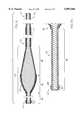
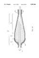
- FIG. 1is a perspective view of an atherectomy device of the invention
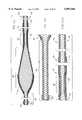
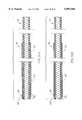
- FIG. 2is a broken-away, longitudinal cross-sectional view of the enlarged diameter tissue removal section of the atherectomy device shown in FIG. 1;
- FIG. 3is a broken-away, longitudinal cross-sectional view of the enlarged diameter tissue removal section of a prior art atherectomy device
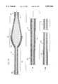
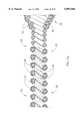
- FIG. 4is a broken-away, longitudinal cross-sectional view of the atherectomy device of FIG. 2 depicted in a slightly curved configuration;
- FIG. 5is a broken-away, longitudinal cross-sectional view of the prior art atherectomy device of FIG. 3 depicted in a slightly curved configuration;
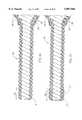
- FIG. 6is a broken-away, longitudinal cross-sectional view of the atherectomy device of FIG. 2 depicted in a more tightly curved configuration;
- FIG. 7is a broken-away, longitudinal cross-sectional view of the prior art atherectomy device of FIG. 3 depicted in a more tightly curved configuration;
- FIG. 8is a broken-away, longitudinal cross-sectional view of a mandrel used in manufacturing a rotational atherectomy device of the invention.
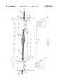
- FIG. 9is a broken-away, longitudinal cross-sectional view of a modified embodiment of the invention having a distal end segment coated with abrasive material to define a second abrasive segment at the very distal end of the atherectomy device;
- FIG. 9Ais an enlarged view of the distal section of the atherectomy device of FIG. 9;
- FIG. 10is a broken-away, longitudinal cross-sectional view of a modified embodiment of the invention having a distal end segment partially coated with abrasive material to define a second abrasive segment at the very distal end of the atherectomy device;
- FIG. 10Ais an enlarged view of the distal section of the atherectomy device of FIG. 10;
- FIG. 11is a broken-away, longitudinal cross-sectional view of a modified embodiment of the invention having a layer of tubing covering the section of the drive shaft in between the two abrasive segments of the atherectomy device;
- FIG. 11Ais an enlarged view of the distal section of the atherectomy device of FIG. 11;
- FIG. 12is a broken-away, longitudinal cross-sectional view of a modified embodiment of the invention having a distal section with a diameter smaller than the diameter of the proximal section of the atherectomy device;
- FIG. 12Ais an enlarged view of the distal section of the atherectomy device of FIG. 12;
- FIG. 12Bis an enlarged view of portions of the proximal section of the atherectomy device of FIG. 12;
- FIG. 13is a broken-away, longitudinal cross-sectional view of a modified embodiment of the invention having a distal section with a reduced diameter, and a single reduced diameter segment located proximally of the enlarged diameter tissue removal section;
- FIG. 13Ais an enlarged view of the distal section of the atherectomy device of FIG. 13;
- FIG. 13Bis an enlarged view of portions of the proximal section of the atherectomy device of FIG. 13;
- FIG. 14is a perspective view of a clamp used in manufacturing the rotational atherectomy device shown in FIG. 13, which has a distal section with a reduced diameter, and a single reduced diameter segment located proximally of the enlarged diameter tissue removal section;
- FIG. 14Ais a longitudinal cross-sectional view of the clamp of FIG. 14;
- FIG. 14Bis an enlarged view showing in longitudinal cross-section details of a portion of FIG. 14A;
- FIG. 15is an enlarged cross-sectional view, partially broken away, of FIG. 14A, taken along lines 15--15 thereof;
- FIG. 16is a broken-away, longitudinal cross-sectional view of a modified embodiment of the invention with a distal section having a segment with a reduced diameter, and a similar reduced diameter segment located proximally of the enlarged diameter tissue removal section;
- FIG. 16Ais an enlarged view of the distal section of the atherectomy device of FIG. 16;
- FIG. 16Bis an enlarged view of portions of the proximal section of the atherectomy device of FIG. 16;
- FIG. 17is a broken-away, longitudinal cross-sectional view of a modified embodiment of the invention with a distal section having two segments with a reduced diameter, and a similar reduced diameter segment located proximally of the enlarged diameter tissue removal section;
- FIG. 17Ais an enlarged view of the distal section of the atherectomy device of FIG. 17;
- FIG. 17Bis an enlarged view of portions of the proximal section of the atherectomy device of FIG. 17;
- FIG. 18is a broken-away, longitudinal cross-sectional view of a modified embodiment of the invention with a distal section having two segments with a reduced diameter, and two similar reduced diameter segments located proximally of the enlarged diameter tissue removal section;
- FIG. 19is a broken-away, longitudinal cross-sectional view of a modified embodiment of the invention similar to FIG. 13, but wound from a single strand of wire;
- FIG. 20is a broken-away, longitudinal cross-sectional view of an atherectomy device of the invention, showing both the extent of coverage by the abrasive material of the enlarged diameter tissue removal section of the rotational atherectomy device, and a moved position of the wire turns of the enlarged diameter tissue removal section of the device when the wire turns are unwinding under load;
- FIG. 21is a broken-away, longitudinal cross-sectional view of another embodiment of an atherectomy device similar to FIG. 20, the wire turns, in their moved position, being depicted as unwinding to a slightly larger diameter;
- FIG. 22is a broken-away, longitudinal cross-sectional view of an atherectomy device similar to FIG. 20, with the proximal end of the abrasive segment terminating at the maximum diameter of the enlarged diameter tissue removal section;
- FIG. 23is a broken-away, longitudinal cross-sectional view of an atherectomy device similar to FIG. 21, with the proximal end of the abrasive segment terminating at the maximum diameter of the enlarged diameter tissue removal section;
- FIG. 24is a broken-away, longitudinal cross-sectional view of an atherectomy device of the invention, with the proximal end of the abrasive segment terminating distally of the maximum diameter of the enlarged diameter tissue removal section;
- FIG. 25is an enlarged longitudinal cross-sectional view of a portion of a rotational atherectomy device of the invention, illustrating changes in the longitudinal cross-sectional profile of its enlarged diameter tissue removal section;
- FIG. 26is a broken-away, longitudinal cross-sectional view of another atherectomy device of the invention, illustrating a slightly different profile of the enlarged diameter tissue removal section;
- FIG. 27is an enlarged view of a portion of the atherectomy device of FIG. 26, illustrating the changes in the longitudinal cross-sectional profile of its enlarged diameter tissue removal section;
- FIG. 28is a broken-away, longitudinal cross-sectional view of another atherectomy device of the invention, illustrating a different profile of the enlarged diameter tissue removal section;
- FIG. 29is a broken-away, longitudinal cross-sectional view of another atherectomy device of the invention, illustrating yet another profile of the enlarged diameter tissue removal section;
- FIGS. 30A and 30Bare broken-away, longitudinal cross-sectional views of atherectomy devices of the invention, illustrating proportionality of such devices of different sizes;
- FIGS. 31A and 31Bare broken-away, longitudinal cross-sectional views of atherectomy devices of the invention, each having a distal end segment coated with abrasive material to define a distal end abrasive segment;
- FIG. 32is a broken-away, longitudinal cross-sectional view of a distal section of a modified atherectomy device of the invention with wire turns of the distal section having a thin external coating of a radio-opaque material;
- FIG. 33is a broken-away, longitudinal cross-sectional view of a distal section of a modified embodiment similar to FIG. 32, but with the radio-opaque material coating the entire circumference of wire turns in the distal section of the atherectomy device;
- FIG. 34is a broken-away, longitudinal cross-sectional view of a distal section of another modified embodiment similar to FIG. 33, but with the radio-opaque material coating all but the inner surface of wire turns in the distal section of the atherectomy device;
- FIG. 35is a broken-away, longitudinal cross-sectional view of a distal section of a modified atherectomy device of the invention with the distal end encapsulated by a generally cylindrical ring made from a radio-opaque material;
- FIG. 36is a broken-away, longitudinal cross-sectional view of the distal section of a modified atherectomy device of the invention with the distal end rounded off;
- FIG. 37is a broken-away, longitudinal cross-sectional view of the embodiment of FIG. 36 with the distal end coated with a bonding material to secure the wire turns to one another;
- FIG. 38is a broken-away, longitudinal cross-sectional view of the distal section of a modified atherectomy device of the invention with the distal end trimmed off "square";
- FIG. 39is a broken-away, longitudinal cross-sectional view of the embodiment of FIG. 38 with the distal end coated with a bonding material to secure the wire turns to one another;
- FIG. 40is a broken-away, longitudinal cross-sectional view of the distal section of a modified atherectomy device of the invention with the distal end electroplated before being trimmed to its finished length;
- FIG. 41is a broken-away, longitudinal cross-sectional view of the embodiment of FIG. 40 with the distal end trimmed to its finished length;
- FIG. 42is a broken-away, longitudinal cross-sectional view of a modified embodiment of the invention having a drive shaft with two distally tapered segments;
- FIG. 43is a broken-away, longitudinal cross-sectional view of a mandrel used in manufacturing the atherectomy device of FIG. 42.
- FIG. 1illustrates a typical rotational atherectomy device of the invention.
- the deviceincludes a handle portion 10, an elongated, flexible drive shaft 20 having an enlarged diameter tissue removal section 28, and an elongated catheter 13 extending distally from the handle portion 10.
- the drive shaft 20is constructed from helically coiled wire, preferably multifilar.
- the catheter 13has a lumen in which most of the length of the drive shaft 20 is disposed, the enlarged diameter tissue removal section 28 extending distally beyond the distal end of the catheter 13.
- the drive shaft 20also contains an inner lumen, permitting the drive shaft 20 to be advanced and rotated over a guide wire 15.
- the handle 10desirably contains a turbine (or similar rotational drive mechanism) for rotating the drive shaft 20 at high speeds.
- the handle 10typically may be connected to a power source (such as compressed air), a source of physiologic solution (used for cooling and lubrication), through suitable tubing, which are not illustrated for the sake of clarity (details regarding such handles and associated instrumentation are well know in the industry, and are described, e.g., in U.S. Pat. No. 5,314,407, issued to Auth).
- the handle 10also desirably includes a control knob 11 for advancing and retracting the turbine and drive shaft 20 with respect to the catheter 13 and the body of the handle.
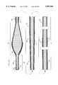
- FIG. 2shows more details of the enlarged diameter tissue removal section 28.
- the section 28includes proximal and distal portions.
- Wire turns 31 of the proximal portion 30 of the tissue removal section 28have diameters that progressively increase distally at a generally constant rate, thereby forming generally the shape of a cone.
- the conical shape of the proximal portion 30 of the tissue removal section 28gives desirable performance characteristics, which will be discussed in greater detail below.
- Wire turns of the distal portion 40have diameters that gradually decrease distally (preferably at a varying rate) thereby forming a generally convex distal portion 40.
- At least part of the tissue removal section 28includes an external coating of an abrasive material 24 to define an abrasive segment of the drive shaft 20.
- the abrasive materialmay be any suitable material, such as diamond powder, fused silica, titanium nitride, tungsten carbide, aluminum oxide, boron carbide, or other ceramic materials.
- the abrasive materialis comprised of diamond chips (or diamond dust particles) attached directly to the wire turns of the drive shaft 20 by a suitable binder 26--such attachment may be achieved using well known techniques, such as conventional electroplating or fusion technologies (see, e.g., U.S. Pat. No. 4,018,576).
- a portion of the drive shaft 20 proximal to the enlarged tissue removal section 28is encased in a thin, flexible, low friction sheath or coating 22.
- the sheath or coating 22is sufficiently long so that its proximal end remains disposed inside the catheter 13 even when the drive shaft 20, with its enlarged diameter tissue removal section 28 is fully advanced distally with respect to the catheter 13.
- Applicantshave successfully utilized heat shrinkable polytetrafluoroethylene tubing to make such sheath 22.
- Such sheath or coating 22may be made from other suitable materials.
- FIG. 3depicts an enlarged diameter tissue removal section 28' of a prior art atherectomy device similar to that described in U.S. Pat. No. 5,314,438 (Shturman).
- the enlarged diameter tissue removal sections 28 and 28'are shown in a generally straight (i.e., "at rest") configuration.
- FIGS. 4 and 5illustrate the differences in certain performance characteristics of the atherectomy device of the invention in comparison to the prior art device.
- each of the deviceshas been bent into a curved configuration with a radius of curvature which is relatively large.
- Each of the devicesis illustrated as being constructed from tri-fiar helical windings of wire, and all but the abrasive segments of both devices are generally flexible.
- FIG. 4illustrates an advantage of the invention over the prior art. Applicants have found that by providing the proximal portion 30 of the enlarged diameter section 28 of the drive shaft 20 with a generally conical shape, the wire turns 31 tend to stay in alignment as this portion of the drive shaft is bent into a curved configuration. Alignment of the wire turns 31 in FIG. 4 can easily be compared to the misalignment of the wire turns in FIG. 5 by reference to the hypothetical center lines 32 and 32'.
- the atherectomy device of FIG. 4illustrates a device having an enlarged diameter tissue removal section 28 with a maximum diameter of about 2.1 mm, bent into a curved configuration with a radius of curvature of about 10 mm.
- FIGS. 6 and 7illustrate this effect even more dramatically, as both an atherectomy device of the invention (FIG. 6) and a prior art atherectomy device (FIG. 7) are bent into a curved configuration with a smaller radius of curvature.
- the misalignment of wire turns in the prior art device (FIG. 7)becomes more severe, while the wire turns of the device of the invention (FIG. 6) stay well-aligned.
- the atherectomy device of FIG. 6illustrates a device having an enlarged diameter tissue removal section 28 with a maximum diameter of about 2.1 mm, bent into a curved configuration with a radius of curvature of about 5 mm.
- Helically wound multifilar drive shafts usable in the inventionmay be manufactured by winding suitable wires about a mandrel.
- FIG. 8depicts a mandrel 50 usable to construct the enlarged diameter tissue removal section 28 of the atherectomy device depicted in FIGS. 2, 4 and 6.
- the mandrelincludes a round central mandrel shaft 52 having a generally constant diameter along its entire length.
- An enlarged portion 54may be manufactured from suitable materials. For example, it may be machined from, e.g., brass (such as round brass rod sold by Vincent Metals, of Minneapolis, Minn.
- This enlarged portion 54is disposed on the mandrel shaft 52 at the desired location, and is then secured in place with a suitable material, such as solder 56.
- solder 56a suitable material
- the solder compositionis 61% tin and 39% lead.
- the flux used in soldering the enlarged portion 54 to the mandrel shaft 52preferably is comprised of 75% ZnCl 2 and 25% NH 4 Cl, these compounds being dissolved in distilled water at maximum concentration (i.e., creating a saturated solution).
- the solder jointmay be further machined or sanded to achieve a desirably smooth transition from the diameter of the enlarged portion 54 to the diameter of the mandrel shaft 52.
- suitable wiresmay be wound about the mandrel shaft 52 and the enlarged portion 54, and the entire unit (or, preferably, just the enlarged diameter tissue removal section 28, together with that portion of the drive shaft 20 that is distal to the enlarged diameter tissue removal section 28 and about 80 mm of the drive shaft proximal to the enlarged diameter tissue removal section 28) may then be heat treated to give the wire the desired "set.”
- the heat treatmentis in the range of about 360° C. to about 560° C. for about one hour to give the wire the desired set.
- the particular temperature selectedwill depend on the type of wire used and the maximum diameter of the enlarged diameter tissue removal section.
- Applicantshave successfully used stainless steel helically wound wire with a diameter of about 0.006 inches for drive shafts having tissue removal sections with diameters of about 1.75 mm or less, and about 0.007 inches for drive shafts having tissue removal sections with diameters of about 1.75 mm or more.
- Applicantshave successfully used stainless steel wire available from Fort Wayne Metals Research Products Corp. (Fort Wayne, Ind.) under the names "Spring Temper” and "Hyten” (both being type 304 stainless steel wire).
- the mandrelis then removed. Because the enlarged portion 54 of the mandrel has a diameter exceeding the diameter of the mandrel shaft 52, the enlarged portion 54 of the mandrel 50 must be removed before the remaining portion of the mandrel may be withdrawn from within the helically wound drive shaft. Applicants have found that the enlarged portion 54 of the mandrel may suitably be removed by constructing the mandrel from materials different from the drive shaft wire, and then dissolving at least the enlarged portion 54 of the mandrel 50.
- the mandrel shaft 52may be made from high carbon steel, the enlarged portion 54 from brass (as described above), and the helically wound wire from stainless steel (such as the type 304 Spring Temper or Hyten stainless steel wire mentioned above).
- boiling nitric acidtypically at about 107° C.
- the actual time it takes to completely dissolve the immersed portion of the mandrel 50depends on the size of the spaces between wire turns of the drive shaft and diameter of the enlarged portion 54 of the mandrel (smaller spaces require longer times, and larger diameters of the enlarged portion 54 of the mandrel require longer times).
- the drive shaft wiresare not adversely affected by the nitric acid.
- the remaining proximal portion of the mandrel shaft 52may then be easily removed.
- the entire drive shaftpreferably is heat treated at temperatures ranging from 200 to 300° C. to relieve stresses in the wire turns of the drive shaft.
- the drive shaftthen is finished by electropolishing.
- FIGS. 9 and 9Adepict the entire length of a modified embodiment of the atherectomy device of the invention (including the proximal end portion 18 of the drive shaft 20) in which the distal section 60 of the drive shaft 20 (i.e., that portion of the drive shaft 20 which is distal to the enlarged diameter tissue removal section 28 of the drive shaft 20) includes a distal end segment 64. Desirably at least a portion of the distal end segment 64 is provided with an external coating of an abrasive material 24' (secured by a suitable binder 26') to define a second abrasive segment at the distal end of the drive shaft 20.
- an abrasive material 24'secured by a suitable binder 26'
- This second abrasive segmentpreferably has an outer diameter which decreases distally to define a generally convex outer surface--preferably the inner diameter of the distal end segment is generally constant, and, thus, it is the cross-sectional thickness of the wire turns of the distal end segment 64 which decreases distally to form the generally convex outer surface of the distal end segment 64 of the drive shaft 20.
- the second abrasive segment of the drive shaft 20enables the rotating drive shaft of the atherectomy device to be advanced across even a very tight stenosis.
- the rotating abrasive segment of the distal end segment 64opens the stenosis to a diameter sufficient to permit advancement of the distal section 60 of the drive shaft 20 across the stenosis until the abrasive material 24 of the enlarged diameter section 28 of the drive shaft 20 engages the stenotic material.
- the enlarged diameter section 28then is used to open the stenosis to a diameter equal to (or, due to slight vibrations of the enlarged diameter section 28, usually somewhat larger than) the largest outer diameter of the enlarged diameter section 28 of the drive shaft 20.
- FIG. 9Ashows abrasive material 24' covering essentially all of the distal end segment 64.
- FIGS. 10 and 10Adepict a slightly modified embodiment where the binder material 26' secures adjacent wire turns of the distal end segment to one another (as in FIGS. 9 and 9A), but abrasive material 24' covers only a portion of the binder material 26'.
- FIGS. 11 and 11Adepict an embodiment similar to FIGS. 9 and 9A, but with the addition of a thin, flexible, low friction sheath or coating 23 encasing at least a substantial portion of the distal section 60 between the abrasive material 24 of the enlarged diameter section 28 and the abrasive material 24' of the distal end segment 64.
- the sheath or coating 23 covering the substantial portion of the distal section 60 of the drive shaft 20may be made from the same material as the sheath or coating 22 covering the portion of the drive shaft 20 immediately proximal to the enlarged diameter tissue removal section 28.
- applicantshave successfully utilized heat shrinkable polytetrafluoroethylene tubing.
- FIGS. 12-18depict various embodiments of the atherectomy device of the invention in which the diameters of certain portions of the drive shaft 20 (other than the enlarged diameter tissue removal section 28) are reduced.
- Reduced diameter segments of the drive shaft 20can be utilized to function as a bearing for rotation of the drive shaft about a guide wire.
- the reduced clearance between the guide wire and the inner surface of the reduced diameter segmentis less than in other portions of the drive shaft and is intended to reduce vibrations of the enlarged diameter section and facilitate smooth rotation of the drive shaft and its enlarged diameter section about the guide wire when the atherectomy device is rotated at high speeds.
- the inner and outer diameters of the distal section 60 of the drive shaft 20are smaller than the corresponding inner and outer diameters of the section of the drive shaft proximal to the enlarged diameter section 28.
- the inner and outer diameters of the distal section 60 of the drive shaft 20are similarly reduced, and there is also a short segment 68, just proximal to the enlarged diameter section 28, which has reduced inner and outer diameters.
- FIGS. 14-15illustrate the use of a clamp in manufacturing the rotational atherectomy device of FIG. 13.
- the particular clamp shown in FIGS. 14-15is used to manufacture the specific rotational atherectomy device depicted in FIG. 13, but it will be understood that variations on this clamp may be utilized to make any of the various embodiments depicted in FIGS. 12-13, as well as FIGS. 17-18, described below.
- the clampincludes a clamp frame 72 with a slot 73, two sets of clamping blocks 74 and 75, and a pair of set screws 78.
- the clamp 72is secured on the drive shaft at the appropriate location. This is accomplished by first passing the drive shaft through the slot 73 in the clamp frame 72, next positioning the clamping blocks 74 and 75 about the drive shaft 20 and moving them into the clamp frame 72, and finally tightening set screws 78 to firmly clench the drive shaft with its enlarged diameter tissue removal section 28 between the clamping blocks 74 and 75.
- FIG. 14Aillustrates in longitudinal cross-section how the drive shaft 20 is clenched by clamping blocks 74 and 75.
- FIGS. 14B and 15the portions of the drive shaft not captured by the clamp are shown as having unwound to a diameter larger than the diameter of the portion captured by the clamp.
- FIGS. 14A and 14Bsignificantly exaggerate the degree of unwinding--typically the outer diameter of the drive shaft, as a result of unwinding, will expand only about 1% to about 10%.
- the section of the drive shaft which is distal to the enlarged diameter section 28, the enlarged diameter tissue removal section 28 itself, and about 80 mm of the drive shaft 20 proximal to the enlarged diameter tissue removal section 28are heat treated (as described above) to give the wires of these portions of the drive shaft the desired "set.”
- the clampmay be removed.
- the drive shaftthen may be further processed as described above (including removal of the mandrel, second heat treatment and electropolishing).
- the reduced diameter distal section 60(i.e., the portion of the drive shaft 20 distal to the enlarged diameter section 28) preferably is about 10-12 mm long, and may be formed by trimming off the drive shaft 20 proximally to the area (or in the area) where the distal set of clamping blocks 75 was located.
- FIGS. 16, 16A and 16Bdepict another rotational atherectomy device in which most of the length of the relatively long distal section 60 has inner and outer diameters equal to the inner and outer diameters of most of the length of the drive shaft 20, except for a relatively short reduced diameter segment 68 located just distal to the enlarged diameter section 28.
- the rest of the atherectomy device depicted in FIGS. 16, 16A and 16Bdoes not differ from the device depicted in FIGS. 13, 13A and 13B.
- the atherectomy device in FIGS. 16, 16A and 16Bhas two relatively short reduced diameter segments 68, one being located just proximal to the enlarged diameter section 28, and the other being located just distal to the enlarged diameter section 28.
- FIGS. 17, 17A and 17Bdepict a similar embodiment having two reduced diameter segments 68 distal to the enlarged diameter tissue removal section 28, and one reduced diameter segment 68 just proximal to the enlarged diameter section 28.
- FIG. 18depicts yet another embodiment, this one having two reduced diameter segments 68 distal to the enlarged diameter section 28, and two reduced diameter segments 68 proximal to the enlarged diameter section 28.
- Selection of the number and location of the reduced diameter segmentscan be made based on the performance characteristics desired. Preferably at least one of such reduced diameter segments is located within about one inch from the enlarged diameter tissue removal section 28, and most preferably within about a quarter inch from such enlarged diameter tissue removal section 28.
- FIG. 19shows an embodiment generally similar to the embodiment depicted in FIGS. 13--13B--5both the embodiment of FIG. 13 and the embodiment of FIG. 19 include a drive shaft 20 having a distal section 60 with reduced inner and outer diameters, as well as a short segment 68, just proximal to the enlarged diameter section 28, which also has reduced inner and outer diameters.
- the embodiment of FIG. 19differs, however, in that it is manufactured from a single strand of wire. Use of one wire strand (as opposed to multiple wire strands) facilitates manufacture of the device by spring coiling machine technology, such as that which is commercially available from, e.g., WMC WAFIOS Machinery Corp. of Branford, Conn.
- FIG. 19utilizes slightly larger diameter wire (e.g., about 0.009-0.010 inch diameter, whereas the embodiment of FIG. 13 can be made from wire as thin as about 0.006-0.007 inches). This gives the drive shaft 20 (excluding the enlarged diameter tissue removal section 28) of the device of FIG. 19 a slightly larger outer diameter than the corresponding portions of the drive shaft of the device of FIG. 13, but both devices can be manufactured with drive shafts having the same inner diameters.
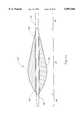
- FIGS. 20-23show several related embodiments of the invention which illustrate a unique performance characteristic of the rotational atherectomy device of the invention.
- the enlarged diameter tissue removal section 28 of the rotational atherectomy devicehas a maximum diameter (measured at line "m") equal to the distance from line d 1 to line d 2 .
- the wire turns 31 of the proximal, generally conical portion 30 of the drive shaft's enlarged diameter section 28are shown in a moved position 31', the wire turns 31 expanding to this position when they unwind under rotational load during use of the atherectomy device.
- Rotational load on the drive shaft 20 in general (and on the generally conical portion 30, in particular)increases rapidly each time when the rotating abrasive segment of the drive shaft (i.e., the portion of the drive shaft covered with abrasive material 24) engages stenotic tissue and consequently the torque applied to the proximal end of the drive shaft by the turbine of the atherectomy device is opposed by the torque of the frictional forces applied to the abrasive segment of the drive shaft when it engages stenotic tissue.
- the abrasive coating 24covers not only the entire distal portion 40 of the enlarged diameter section 28 of the drive shaft, but also a small portion of the enlarged diameter section 28 which is proximal to line "m". Extending the coverage of the abrasive coating 24 proximally of the line "m" results in a more substantial portion of the enlarged diameter tissue removal section 28 being usable for tissue removal.
- the physical configuration of the enlarged diameter section 28is designed so that, under load, wire turns 31 of the proximal, generally conical portion 30 of the enlarged diameter section 28 unwind to the extent that one or more of the wire turns near the distal end of the generally conical portion 30 reach a diameter equal to the "at rest" maximum diameter of the enlarged diameter tissue removal section 28 (measured at line "m").
- wire turns 31 of the proximal, generally conical portion 30 of the enlarged diameter section 28unwind to the extent that one or more of the wire turns near the distal end of the generally conical portion 30 reach a diameter equal to the "at rest" maximum diameter of the enlarged diameter tissue removal section 28 (measured at line "m").
- wire turns of the abrasive segment of the drive shaftare preferably fixed to each other, they are incapable of unwinding.
- the wire turns of the abrasive segmentare preferably bonded to one another by the binder 26 which secures the abrasive coating 24 to the wire turns of the drive shaft.
- FIG. 21illustrates a modified embodiment in which the physical configuration of the enlarged diameter section 28 is designed so that under typical load conditions at least some of the wire turns 31 of the proximal, generally conical portion 30 of the enlarged diameter section 28 unwind to a diameter slightly larger than the "at rest" maximum diameter of the enlarged diameter section 28 (again, measured at line "m").
- the maximum diameter of the wire turns in the moved position 31'is equal to the distance from line d 3 to line d 4 .
- the unwinding of the wire turns of the generally conical portion 30may be significantly reduced or eliminated by stopping the rotation of the turbine (thereby eliminating torque applied to the proximal end of the drive shaft) or by slightly withdrawing the drive shaft 20 (thereby reducing the torque of frictional forces between the abrasive coating 24 and the stenotic tissue).
- Return of the wire turns of the generally conical portion 30 to their normal "at rest" diameterfacilitates withdrawal of the enlarged diameter tissue removal section 28 from the artery once the stenosis has been opened; desirably the drive shaft 20 should continue to be rotated while it is withdrawn, though preferably at a significantly reduced rotational speed.
- the degree of unwinding of the wire turnsis dependent upon a number of parameters including the diameter of the wire, the material from which the wire is made, the maximum diameter of the enlarged tissue removal section 28, and the rotational load applied to the drive shaft.
- the rotational load applied to the drive shaftin turn depends on the torque of the turbine and the drop in rotational speed which is permitted when the rotating abrasive segment engages stenotic tissue to be removed.
- Preferably all these parametersare adjusted so that the desired amount of unwinding of the wire turns is achieved when the tissue removal section 28 of the drive shaft is gently advanced against the stenotic tissue.
- the rotational speed of the drive shaftshould not decrease by more than about 5,000 rpm under such gentle advancement against stenotic tissue.
- Such relatively small drop in the rotational speed of the drive shaftshould not produce either excessive heat at the atherectomy site or a substantial increase in the size of the tissue particles removed. This drop in rotational speed, however, allowed Applicants to achieve a practically useful amount of unwinding of the wire turns of the generally conical portion 30 of the drive shaft for drive shafts having enlarged diameter segments 28 with maximum diameters of about 2 mm or larger.
- FIGS. 22 and 23are similar to FIGS. 20 and 21, but differ in that the abrasive coating 24 in each of these embodiments covers only the distal portion 40 of the enlarged diameter section 28 of the drive shaft, and does not extend into the proximal generally conical portion 30 of the enlarged diameter section 28 of the drive shaft 20 (i.e., the abrasive coating terminates at line "m", the location of the maximum “at rest” diameter of the enlarged diameter section 28).
- FIG. 24is similar to FIGS. 21 and 23 in that, under typical load conditions, at least some of the wire turns 31 of the proximal, generally conical portion 30 of the enlarged diameter section 28 (and, in the FIG. 24 embodiment, some of the proximal wire turns of the distal portion 40 of the enlarged diameter section 28) unwind to a diameter slightly larger than both the "at rest" maximum diameter of the enlarged diameter tissue removal section 28, and, more importantly, the maximum diameter of the abrasive coating 24.
- This embodimentdiffers, however, from FIGS. 21 and 23 in that the abrasive coating 24 in this embodiment covers only part of the distal portion 40 of the enlarged diameter section 28 of the drive shaft.
- the abrasive coatingcovers only a distal part of the enlarged diameter section's distal portion 40, the coating terminating at line “n” on FIG. 24. Because the abrasive coating 24 does not extend proximally beyond line “n", the maximum diameter of the abrasive coating 24 (i.e., the distance from line d 1 to line d 2 , as measured at line “n") is about equal to the maximum "at rest” diameter of the enlarged diameter section 28 (i.e., the distance from line d 1 to line d 2 , as measured at line “m”). Under typical load conditions, however, the wire turns 31 of the enlarged diameter section 28 at line “m” unwind to a diameter slightly larger than the maximum diameter of the abrasive coating 24.
- FIG. 25shows in enlarged detail changes in the longitudinal cross-sectional profile of the enlarged diameter tissue removal section 28 of the rotational atherectomy device depicted in FIG. 2.
- Wire turns of the proximal portion 30 of the tissue removal section 28have diameters that increase distally at a generally constant rate, thereby forming a generally conical proximal section.
- Wire turns of the distal portion 40 of the enlarged diameter section 28have diameters that gradually decrease distally thereby forming a generally convex distal portion 40 having a longitudinal cross-section with a first radius of curvature R 1 .
- the enlarged diameter sectionincludes an intermediate transitional portion 42 between the generally conical proximal section and the generally convex distal portion, the transitional portion 42 having wire turns with diameters that gradually decrease proximally, thereby forming a generally convex transitional portion 42 having a longitudinal cross-section with a second radius of curvature R 2 which is smaller than the first radius of curvature R 1 .
- the transitional portion 42thus provides a smooth transition from the generally conical proximal portion 30 of the enlarged diameter section 28 to the convex distal portion 40 of the enlarged diameter section 28.
- FIGS. 26 and 27depict a rotational atherectomy device having an enlarged diameter tissue removal section 28 with a slightly different longitudinal cross-sectional profile.
- the first radius of curvature R 1 of the distal portion 40 of the tissue removal section 28is smaller than the second radius of curvature R 2 of the intermediate transitional portion 42 of the tissue removal section 28.
- FIG. 28depicts an enlarged diameter tissue removal section 28 of a rotational atherectomy device having another different longitudinal cross-sectional profile.
- the distal portion 40 of the enlarged diameter section 28has an essentially hemispherical configuration, directly abutting the proximal conical portion 30 (i.e., there is no intermediate transitional portion).
- FIG. 29shows yet another variation of the longitudinal profile of an enlarged diameter tissue removal section 28, which employs a generally cylindrical transitional portion 44 between the hemispherical distal portion 40 and the conical proximal portion 30. It will be understood that other variations on these profiles may be readily constructed by one of ordinary skill in the art.
- FIGS. 30A and 30Billustrate an advantage of the rotational atherectomy device of the invention.
- the enlarged diameter tissue removal section 28 of the device in FIG. 30Ae.g., may have a diameter of about 1.5 mm and a length of about 4.1 mm
- the enlarged diameter tissue removal section 28 of the device in FIG. 30Be.g., may have a diameter of about 2.1 mm and a length of about 6.1 mm. Note that these two enlarged diameter tissue removal sections are generally geometrically proportional to one another, notwithstanding being of different diameters.
- FIGS. 31A and 31Billustrate two embodiments which each utilize an external coating of an abrasive material 24' (secured by a suitable binder 26') on a portion of the distal end segment of the drive shaft 20 to define a single abrasive segment 64 at the distal end of the drive shaft 20.
- These embodimentsthus differ from the atherectomy device depicted in FIG. 11 in that the rotational atherectomy devices of FIGS. 31A and 31B have no enlarged diameter section 28.
- the abrasive segment 64preferably has an outer diameter which decreases distally to define a generally convex outer surface--preferably the inner diameter of the distal end segment is generally constant, and, thus, it is the cross-sectional thickness of the wire turns of the abrasive segment 64 which decreases distally to form the generally convex outer surface of the abrasive segment 64 of the drive shaft 20.
- FIGS. 31A and 31Binclude a thin, flexible, low friction sheath or coating.
- the sheath or coating 23is of such a thickness that its outer diameter is approximately equal to the maximum (abrasive coated) outer diameter of the abrasive segment 64.
- the sheath or coating 23'is thinner--i.e., it is of such a thickness that its outer diameter is less than the maximum (abrasive coated) outer diameter of the abrasive segment 64.
- the single abrasive segment 64 of the drive shaft 20enables the rotating drive shaft of the atherectomy device in both of these embodiments to be advanced across even a very tight stenosis.
- Such low profile atherectomy devicesmay be particularly useful in preparing a very tight stenosis for further opening by another atherectomy device, e.g., having an enlarged diameter tissue removal section 28 as described above, or for other medical procedures such as balloon angioplasty.
- FIG. 32illustrates use of a radio-opaque coating 80 deposited on the outer surface of wire turns 31 of a substantial portion of the distal section 60 of the drive shaft 20. Suitable coatings may be obtained by deposition of platinum or other radio-opaque alloys.
- the radio-opaque material 80is shown as entirely encapsulating the wire turns 31 of a substantial portion of the distal section 60 of the drive shaft 20 (but the radio-opaque material does not fixate adjacent turns 31 of the drive shaft to one another, thus preserving the flexibility of the distal section 60 of the drive shaft).
- FIG. 34illustrates a variation of FIG. 33 in which the radio-opaque material 80 deposited on the wire turns 31 of drive shaft's distal section 60 uniformly covers the wire turns 31 except for the inner surface of the wire turns 31.
- a configurationmay be obtained by first coating the wire turns 31 uniformly with the radio-opaque material 80 and then removing that portion of the material which would otherwise reduce the inner diameter of the drive shaft lumen, therefore leaving generally flat inner surfaces 81 on the wire turns 31 as shown in the drawing.
- a mandrel or similar devicemay be placed in the drive shaft lumen before coating the wire turns 31 with radio-opaque material 80 so as to prevent reduction of the inner diameter of this portion of the drive shaft by the radio-opaque material 80.
- Other suitable manufacturing techniquesmay also be utilized.
- FIG. 35illustrates use of a marker in the form of a platinum or other suitable radio-opaque collar 84 secured (such as by solder 86 or other suitable material) to the distal end of the distal section 60 of the drive shaft.
- the collar 84includes a distal end having an opening 85 with an inner diameter equal to or larger than the inner diameter of the drive shaft lumen.
- the collar 84provides good radiological imaging of the distal end of the rotational atherectomy device, and the solder attaching the collar 84 to the wire turns 31 also serves to secure the wire turns 31 of the distal end segment 64 of the drive shaft to one another.
- FIGS. 36-41depict alternative techniques for finishing the distal end segment of the drive shaft.
- the very distal ends of the wire turns 31are first rounded off (as by machining) to the profile depicted in FIG. 36.
- the distal end segment 64is then coated with a suitable bonding material 87 to secure the wire turns 31 to one another (FIG. 37).
- electro-depositioni.e., electroplating
- nickelis electro-deposited only on the outer surfaces of the wire turns 31 so that the inner diameter of the drive shaft 20 is not affected.
- the above-described maskingmay be accomplished by filling the lumen of the drive shaft with a shaft or filament made from tetrafluoroethylene or other suitable materials.
- FIGS. 38 and 39depict an alternative technique in which, rather than rounding off the distal end of the drive shaft 20 (as is depicted in FIG. 36), the distal end of the drive shaft is simply trimmed off "square" and then electroplated as described above.
- FIGS. 40 and 41depict a particularly preferred technique in which the distal end segment 64 is electroplated before being trimmed to its finished length, as shown in FIG. 40.
- the drive shaft 20is trimmed to its finished length and the distal end segment 64 may be rounded off (as by machining) to form a generally convex outer surface of the distal end segment of the drive shaft, as depicted in FIG. 41.
- This techniquehas the advantage that final machining of the distal end segment 64 to its finished profile is more easily accomplished when the wire turns 31 have been secured to one another by the electro-deposition material.
- the plating metal 87may optionally include metals that are more radio-opaque than stainless steel.
- nickelwhich is somewhat more radio-opaque than stainless steel, may be used as an electro-deposition metal.
- an overcoat of platinum (or other highly radio-opaque material)may be deposited over the nickel layer, or may be sandwiched between successive layers of nickel.
- electro-deposited nickelmay be used as a binder to secure abrasive material to the distal end segment 64, as described above, e.g., with reference to FIG. 9.
- FIG. 42depicts a rotational atherectomy device having a drive shaft 20 with generally constant inner and outer diameters along most of its length. It also has two distally tapered segments 69 and 69', one (69) being just proximal to the enlarged diameter section 28, and the other (69') being in the distal section 60 of the drive shaft 20.
- FIG. 43is a broken-away, longitudinal cross-sectional view of a mandrel 50' which may be used to manufacture an atherectomy device having a drive shaft 20 with the tapered profile depicted in FIG. 42. The mandrel 50' is similar in most respects to the mandrel 50 depicted in FIG.
- mandrel shaft 52'is tapered distally along both a proximal section 46 and a distal section 48, the intermediate section 47 having a generally constant diameter.
- mandrel shaftscan be manufactured using, e.g., computer controlled centerless grinding systems available from Glebar Company of Franklin Lakes, N.J. The degree of taper is somewhat exaggerated in FIGS. 42-43 for illustrative purposes.
Landscapes
- Health & Medical Sciences (AREA)
- Surgery (AREA)
- Life Sciences & Earth Sciences (AREA)
- Medical Informatics (AREA)
- Nuclear Medicine, Radiotherapy & Molecular Imaging (AREA)
- Engineering & Computer Science (AREA)
- Biomedical Technology (AREA)
- Heart & Thoracic Surgery (AREA)
- Vascular Medicine (AREA)
- Molecular Biology (AREA)
- Animal Behavior & Ethology (AREA)
- General Health & Medical Sciences (AREA)
- Public Health (AREA)
- Veterinary Medicine (AREA)
- Surgical Instruments (AREA)
- Micro-Organisms Or Cultivation Processes Thereof (AREA)
Abstract
Description
Claims (47)
Priority Applications (6)
| Application Number | Priority Date | Filing Date | Title |
|---|---|---|---|
| US08/679,470US5897566A (en) | 1996-07-15 | 1996-07-15 | Rotational atherectomy device |
| CA002262873ACA2262873A1 (en) | 1996-07-15 | 1997-07-03 | Rotational atherectomy device |
| AU35955/97AAU728697C (en) | 1996-07-15 | 1997-07-03 | Rotational atherectomy device |
| PCT/US1997/011758WO1998002101A1 (en) | 1996-07-15 | 1997-07-03 | Rotational atherectomy device |
| EP97932515AEP0921761A4 (en) | 1996-07-15 | 1997-07-03 | Rotational atherectomy device |
| US09/597,959US6295712B1 (en) | 1996-07-15 | 2000-06-20 | Rotational atherectomy device |
Applications Claiming Priority (1)
| Application Number | Priority Date | Filing Date | Title |
|---|---|---|---|
| US08/679,470US5897566A (en) | 1996-07-15 | 1996-07-15 | Rotational atherectomy device |
Related Child Applications (1)
| Application Number | Title | Priority Date | Filing Date |
|---|---|---|---|
| US22625499AContinuation | 1996-07-15 | 1999-01-07 |
Publications (1)
| Publication Number | Publication Date |
|---|---|
| US5897566Atrue US5897566A (en) | 1999-04-27 |
Family
ID=24727029
Family Applications (2)
| Application Number | Title | Priority Date | Filing Date |
|---|---|---|---|
| US08/679,470Expired - LifetimeUS5897566A (en) | 1996-07-15 | 1996-07-15 | Rotational atherectomy device |
| US09/597,959Expired - LifetimeUS6295712B1 (en) | 1996-07-15 | 2000-06-20 | Rotational atherectomy device |
Family Applications After (1)
| Application Number | Title | Priority Date | Filing Date |
|---|---|---|---|
| US09/597,959Expired - LifetimeUS6295712B1 (en) | 1996-07-15 | 2000-06-20 | Rotational atherectomy device |
Country Status (5)
| Country | Link |
|---|---|
| US (2) | US5897566A (en) |
| EP (1) | EP0921761A4 (en) |
| AU (1) | AU728697C (en) |
| CA (1) | CA2262873A1 (en) |
| WO (1) | WO1998002101A1 (en) |
Cited By (46)
| Publication number | Priority date | Publication date | Assignee | Title |
|---|---|---|---|---|
| WO1999047056A1 (en) | 1998-03-16 | 1999-09-23 | Shturman Cardiology Systems, Inc. | Rotational atherectomy device with improved exchangeable drive shaft cartridge |
| US6096054A (en)* | 1998-03-05 | 2000-08-01 | Scimed Life Systems, Inc. | Expandable atherectomy burr and method of ablating an occlusion from a patient's blood vessel |
| US6132444A (en)* | 1997-08-14 | 2000-10-17 | Shturman Cardiology Systems, Inc. | Eccentric drive shaft for atherectomy device and method for manufacture |
| US6146395A (en)* | 1998-03-05 | 2000-11-14 | Scimed Life Systems, Inc. | Ablation burr |
| WO2003034898A2 (en) | 2001-10-19 | 2003-05-01 | Shturman Cardiology Systems, Inc. | Control system for rotational angioplasty device |
| US6572630B1 (en) | 2000-01-31 | 2003-06-03 | Rex Medical, L.P | Atherectomy device |
| US6579299B2 (en) | 2000-01-31 | 2003-06-17 | Rex Medical, L.P. | Atherectomy device |
| US20030125756A1 (en)* | 2001-10-19 | 2003-07-03 | Leonid Shturman | Rotational angioplasty device with abrasive crown |
| US20050138792A1 (en)* | 1999-04-26 | 2005-06-30 | Black Damon R. | Method of forming a lead |
| US20050149083A1 (en)* | 2004-01-07 | 2005-07-07 | Dmitriy Prudnikov | Terminal guide for rotational atherectomy device and method of using same |
| US20050209615A1 (en)* | 2004-01-07 | 2005-09-22 | Dmitriy Prudnikov | Orbital atherectomy device guide wire design |
| US20080004646A1 (en)* | 2006-06-30 | 2008-01-03 | Atheromed, Inc. | Atherectomy devices and methods |
| US20080004647A1 (en)* | 2006-06-30 | 2008-01-03 | Atheromed, Inc. | Atherectomy devices and methods |
| US20080004643A1 (en)* | 2006-06-30 | 2008-01-03 | Atheromed, Inc. | Atherectomy devices and methods |
| US20080045986A1 (en)* | 2006-06-30 | 2008-02-21 | Atheromed, Inc. | Atherectomy devices and methods |
| US20080208230A1 (en)* | 2007-02-22 | 2008-08-28 | Singfatt Chin | Expandable rotating device and method for tissue aspiration |
| US20090018566A1 (en)* | 2006-06-30 | 2009-01-15 | Artheromed, Inc. | Atherectomy devices, systems, and methods |
| US20090018567A1 (en)* | 2006-06-30 | 2009-01-15 | Artheromed, Inc. | Atherectomy devices, systems, and methods |
| US20090018565A1 (en)* | 2006-06-30 | 2009-01-15 | Artheromed, Inc. | Atherectomy devices, systems, and methods |
| US20090024085A1 (en)* | 2006-06-30 | 2009-01-22 | Artheromed, Inc | Atherectomy devices, systems, and methods |
| US20090062872A1 (en)* | 2007-08-27 | 2009-03-05 | Singfatt Chin | Balloon cannula system for accessing and visualizing spine and related methods |
| US20090149877A1 (en)* | 2007-12-06 | 2009-06-11 | Cardiovascular Systems, Inc. | Rotational atherectomy device with pre-curved drive shaft |
| US20090234378A1 (en)* | 2007-10-22 | 2009-09-17 | Atheromed, Inc. | Atherectomy devices and methods |
| WO2010002507A1 (en)* | 2008-06-05 | 2010-01-07 | Cardiovascular Systems, Inc. | Directional rotational atherectomy device with offset spinning abrasive element |
| US20110112563A1 (en)* | 2006-06-30 | 2011-05-12 | Atheromed, Inc. | Atherectomy devices and methods |
| US8236016B2 (en) | 2007-10-22 | 2012-08-07 | Atheromed, Inc. | Atherectomy devices and methods |
| US8795306B2 (en) | 2011-10-13 | 2014-08-05 | Atheromed, Inc. | Atherectomy apparatus, systems and methods |
| US20140316447A1 (en)* | 2013-03-14 | 2014-10-23 | Cardiovascular Systems, Inc. | Devices, systems and methods for a piloting tip bushing for rotational atherectomy |
| US20150005791A1 (en)* | 2013-06-28 | 2015-01-01 | Cardiovascular Systems, Inc. | Atherectomy device having combined open/close drive shaft |
| US20150089785A1 (en)* | 2013-09-30 | 2015-04-02 | Cardiovascular Systems, Inc. | Method of attaching an element to a drive shaft |
| US9855070B2 (en) | 2014-03-12 | 2018-01-02 | Boston Scientific Limited | Infusion lubricated atherectomy catheter |
| US20180064464A1 (en)* | 2014-01-15 | 2018-03-08 | Cardio Flow, Inc. | Atherectomy devices and methods |
| US10405878B2 (en) | 2014-07-25 | 2019-09-10 | Boston Scientific Scimed, Inc. | Rotatable medical device |
| US10405879B2 (en) | 2014-12-04 | 2019-09-10 | Boston Scientific Scimed, Inc. | Rotatable medical device |
| US10413318B2 (en)* | 2015-06-01 | 2019-09-17 | Cardiovascular Systems, Inc. | Rotational systems comprising a polymer driveshaft |
| WO2020076771A1 (en)* | 2018-10-08 | 2020-04-16 | Cardiovascular Systems, Inc. | Devices and methods for generating orbital motion in drive shafts for rotational medical devices |
| US10869689B2 (en) | 2017-05-03 | 2020-12-22 | Medtronic Vascular, Inc. | Tissue-removing catheter |
| US11207096B2 (en) | 2006-06-30 | 2021-12-28 | Atheromed, Inc. | Devices systems and methods for cutting and removing occlusive material from a body lumen |
| US11272954B2 (en) | 2018-08-07 | 2022-03-15 | Cardio Flow, Inc. | Atherectomy devices and methods |
| US11304723B1 (en) | 2020-12-17 | 2022-04-19 | Avantec Vascular Corporation | Atherectomy devices that are self-driving with controlled deflection |
| US11690645B2 (en) | 2017-05-03 | 2023-07-04 | Medtronic Vascular, Inc. | Tissue-removing catheter |
| US11730509B2 (en) | 2018-10-08 | 2023-08-22 | Cardiovascular Systems, Inc. | Devices and methods for generating orbital motion in drive shafts for rotational medical devices |
| US11819236B2 (en) | 2019-05-17 | 2023-11-21 | Medtronic Vascular, Inc. | Tissue-removing catheter |
| US12220140B1 (en) | 2023-08-16 | 2025-02-11 | Avantec Vascular Corporation | Thrombectomy devices with lateral and vertical bias |
| US12290279B2 (en) | 2021-06-07 | 2025-05-06 | Avantec Vascular Corporation | Hybrid atherectomy devices |
| US12414785B1 (en) | 2025-03-17 | 2025-09-16 | Avantec Vascular Corporation | Cutters with pulsating vacuum control |
Families Citing this family (32)
| Publication number | Priority date | Publication date | Assignee | Title |
|---|---|---|---|---|
| US6217595B1 (en) | 1996-11-18 | 2001-04-17 | Shturman Cardiology Systems, Inc. | Rotational atherectomy device |
| US6183487B1 (en)* | 1997-03-06 | 2001-02-06 | Scimed Life Systems, Inc. | Ablation device for reducing damage to vessels and/or in-vivo stents |
| WO2003043685A2 (en)* | 2001-11-19 | 2003-05-30 | Cardiovascular Systems, Inc | High torque, low profile intravascular guidewire system |
| US7179269B2 (en) | 2002-05-20 | 2007-02-20 | Scimed Life Systems, Inc. | Apparatus and system for removing an obstruction from a lumen |
| JP5219518B2 (en) | 2004-12-09 | 2013-06-26 | ザ ファウンドリー, エルエルシー | Aortic valve repair |
| CA2822381C (en) | 2010-12-23 | 2019-04-02 | Foundry Newco Xii, Inc. | System for mitral valve repair and replacement |
| JP5872692B2 (en) | 2011-06-21 | 2016-03-01 | トゥエルヴ, インコーポレイテッド | Artificial therapy device |
| US11202704B2 (en) | 2011-10-19 | 2021-12-21 | Twelve, Inc. | Prosthetic heart valve devices, prosthetic mitral valves and associated systems and methods |
| US9763780B2 (en) | 2011-10-19 | 2017-09-19 | Twelve, Inc. | Devices, systems and methods for heart valve replacement |
| JP6133309B2 (en) | 2011-10-19 | 2017-05-24 | トゥエルヴ, インコーポレイテッド | Prosthetic heart valve device |
| EA201400478A1 (en) | 2011-10-19 | 2014-10-30 | Твелв, Инк. | DEVICES, SYSTEMS AND METHODS OF PROTESIZING THE HEART VALVE |
| US9039757B2 (en) | 2011-10-19 | 2015-05-26 | Twelve, Inc. | Prosthetic heart valve devices, prosthetic mitral valves and associated systems and methods |
| US9655722B2 (en) | 2011-10-19 | 2017-05-23 | Twelve, Inc. | Prosthetic heart valve devices, prosthetic mitral valves and associated systems and methods |
| US9579198B2 (en) | 2012-03-01 | 2017-02-28 | Twelve, Inc. | Hydraulic delivery systems for prosthetic heart valve devices and associated methods |
| AU2014268631B2 (en) | 2013-05-20 | 2019-08-01 | Twelve, Inc. | Implantable heart valve devices, mitral valve repair devices and associated systems and methods |
| US20150080795A1 (en) | 2013-07-26 | 2015-03-19 | Cardiovascular Systems, Inc. | Devices, systems and methods for performing atherectomy and subsequent balloon angioplasty without exchanging devices |
| US10299820B2 (en) | 2015-02-20 | 2019-05-28 | Cardiovascular Systems, Inc. | Methods and systems for disrupting calcified walls of biological conduits and calcified lesions therein |
| US10238490B2 (en) | 2015-08-21 | 2019-03-26 | Twelve, Inc. | Implant heart valve devices, mitral valve repair devices and associated systems and methods |
| US10702298B2 (en) | 2016-02-26 | 2020-07-07 | Cardiovascular Systems, Inc. | Powerline communication systems and methods for medical devices |
| WO2017189276A1 (en) | 2016-04-29 | 2017-11-02 | Medtronic Vascular Inc. | Prosthetic heart valve devices with tethered anchors and associated systems and methods |
| US10595895B2 (en) | 2016-07-19 | 2020-03-24 | Cardiovascular Systems, Inc. | Rotational medical device with airfoil |
| US11517346B2 (en) | 2017-02-24 | 2022-12-06 | Cardiovascular Systems, Inc. | Gearless cannulated motor assembly and system for rotational atherectomy |
| US10575950B2 (en) | 2017-04-18 | 2020-03-03 | Twelve, Inc. | Hydraulic systems for delivering prosthetic heart valve devices and associated methods |
| US10433961B2 (en) | 2017-04-18 | 2019-10-08 | Twelve, Inc. | Delivery systems with tethers for prosthetic heart valve devices and associated methods |
| US10702378B2 (en) | 2017-04-18 | 2020-07-07 | Twelve, Inc. | Prosthetic heart valve device and associated systems and methods |
| US10792151B2 (en) | 2017-05-11 | 2020-10-06 | Twelve, Inc. | Delivery systems for delivering prosthetic heart valve devices and associated methods |
| US10646338B2 (en) | 2017-06-02 | 2020-05-12 | Twelve, Inc. | Delivery systems with telescoping capsules for deploying prosthetic heart valve devices and associated methods |
| US10709591B2 (en) | 2017-06-06 | 2020-07-14 | Twelve, Inc. | Crimping device and method for loading stents and prosthetic heart valves |
| US10786352B2 (en) | 2017-07-06 | 2020-09-29 | Twelve, Inc. | Prosthetic heart valve devices and associated systems and methods |
| US10729541B2 (en) | 2017-07-06 | 2020-08-04 | Twelve, Inc. | Prosthetic heart valve devices and associated systems and methods |
| DE102018122708B4 (en) | 2018-09-17 | 2025-02-20 | Novaled Gmbh | Organic electronic device, organic semiconducting material and a borane compound |
| CN118697424A (en) | 2018-11-16 | 2024-09-27 | 美敦力瓦斯科尔勒公司 | Tissue Removal Catheter |
Citations (8)
| Publication number | Priority date | Publication date | Assignee | Title |
|---|---|---|---|---|
| US4990134A (en)* | 1986-01-06 | 1991-02-05 | Heart Technology, Inc. | Transluminal microdissection device |
| US5158564A (en)* | 1990-02-14 | 1992-10-27 | Angiomed Ag | Atherectomy apparatus |
| US5192291A (en)* | 1992-01-13 | 1993-03-09 | Interventional Technologies, Inc. | Rotationally expandable atherectomy cutter assembly |
| US5314438A (en)* | 1992-12-17 | 1994-05-24 | Shturman Cardiology Systems, Inc. | Abrasive drive shaft device for rotational atherectomy |
| US5358485A (en)* | 1992-01-13 | 1994-10-25 | Schneider (Usa) Inc. | Cutter for atherectomy catheter |
| US5395311A (en)* | 1990-05-14 | 1995-03-07 | Andrews; Winston A. | Atherectomy catheter |
| US5490859A (en)* | 1992-11-13 | 1996-02-13 | Scimed Life Systems, Inc. | Expandable intravascular occlusion material removal devices and methods of use |
| RU2055991C1 (en)* | 1995-02-21 | 1996-03-10 | Гуськов Игорь Алексеевич | Turbine for driving hand tools |
Family Cites Families (15)
| Publication number | Priority date | Publication date | Assignee | Title |
|---|---|---|---|---|
| US96020A (en)* | 1869-10-19 | Improvement in the manufacture of hollow-rubber goods | ||
| US829801A (en)* | 1904-05-24 | 1906-08-28 | Gen Electric | Method of making hollow articles. |
| US1976522A (en)* | 1933-10-03 | 1934-10-09 | Rca Corp | Method of making grid electrodes |
| US2387321A (en)* | 1944-11-22 | 1945-10-23 | Us Rubber Co | Method of making highly stretchable textile yarn |
| DE1166737B (en)* | 1959-07-25 | 1964-04-02 | Schmid & Wezel | Process for the continuous production of flexible wire hollow, z. B. speedometer shafts |
| US3110098A (en)* | 1960-11-25 | 1963-11-12 | Sylvania Electric Prod | Manufacture of wire coils |
| US3389872A (en)* | 1967-01-25 | 1968-06-25 | George F. Lyman | Reel |
| US3706624A (en)* | 1969-01-21 | 1972-12-19 | Goodrich Co B F | Apparatus for making plastic hose |
| DE2105517A1 (en)* | 1971-02-05 | 1972-08-17 | Patra Patent Treuhand | Method and device for storing, conveying and treating wire coils |
| IN174705B (en)* | 1988-09-09 | 1995-02-18 | Daya Ranjit Senanayake | |
| US5217474A (en) | 1991-07-15 | 1993-06-08 | Zacca Nadim M | Expandable tip atherectomy method and apparatus |
| US5681336A (en) | 1995-09-07 | 1997-10-28 | Boston Scientific Corporation | Therapeutic device for treating vien graft lesions |
| US5766192A (en) | 1995-10-20 | 1998-06-16 | Zacca; Nadim M. | Atherectomy, angioplasty and stent method and apparatus |
| US5772864A (en)* | 1996-02-23 | 1998-06-30 | Meadox Medicals, Inc. | Method for manufacturing implantable medical devices |
| US6132444A (en)* | 1997-08-14 | 2000-10-17 | Shturman Cardiology Systems, Inc. | Eccentric drive shaft for atherectomy device and method for manufacture |
- 1996
- 1996-07-15USUS08/679,470patent/US5897566A/ennot_activeExpired - Lifetime
- 1997
- 1997-07-03AUAU35955/97Apatent/AU728697C/ennot_activeCeased
- 1997-07-03WOPCT/US1997/011758patent/WO1998002101A1/ennot_activeApplication Discontinuation
- 1997-07-03EPEP97932515Apatent/EP0921761A4/ennot_activeWithdrawn
- 1997-07-03CACA002262873Apatent/CA2262873A1/ennot_activeAbandoned
- 2000
- 2000-06-20USUS09/597,959patent/US6295712B1/ennot_activeExpired - Lifetime
Patent Citations (9)
| Publication number | Priority date | Publication date | Assignee | Title |
|---|---|---|---|---|
| US4990134A (en)* | 1986-01-06 | 1991-02-05 | Heart Technology, Inc. | Transluminal microdissection device |
| US4990134B1 (en)* | 1986-01-06 | 1996-11-05 | Heart Techn Inc | Transluminal microdissection device |
| US5158564A (en)* | 1990-02-14 | 1992-10-27 | Angiomed Ag | Atherectomy apparatus |
| US5395311A (en)* | 1990-05-14 | 1995-03-07 | Andrews; Winston A. | Atherectomy catheter |
| US5192291A (en)* | 1992-01-13 | 1993-03-09 | Interventional Technologies, Inc. | Rotationally expandable atherectomy cutter assembly |
| US5358485A (en)* | 1992-01-13 | 1994-10-25 | Schneider (Usa) Inc. | Cutter for atherectomy catheter |
| US5490859A (en)* | 1992-11-13 | 1996-02-13 | Scimed Life Systems, Inc. | Expandable intravascular occlusion material removal devices and methods of use |
| US5314438A (en)* | 1992-12-17 | 1994-05-24 | Shturman Cardiology Systems, Inc. | Abrasive drive shaft device for rotational atherectomy |
| RU2055991C1 (en)* | 1995-02-21 | 1996-03-10 | Гуськов Игорь Алексеевич | Turbine for driving hand tools |
Cited By (133)
| Publication number | Priority date | Publication date | Assignee | Title |
|---|---|---|---|---|
| US6132444A (en)* | 1997-08-14 | 2000-10-17 | Shturman Cardiology Systems, Inc. | Eccentric drive shaft for atherectomy device and method for manufacture |
| US6638288B1 (en) | 1997-08-14 | 2003-10-28 | Shturman Cardiology Systems, Inc. | Eccentric drive shaft for atherectomy device and method for manufacture |
| US6596005B1 (en) | 1998-03-05 | 2003-07-22 | Scimed Life Systems, Inc. | Steerable ablation burr |
| US6096054A (en)* | 1998-03-05 | 2000-08-01 | Scimed Life Systems, Inc. | Expandable atherectomy burr and method of ablating an occlusion from a patient's blood vessel |
| US6146395A (en)* | 1998-03-05 | 2000-11-14 | Scimed Life Systems, Inc. | Ablation burr |
| US6416526B1 (en) | 1998-03-05 | 2002-07-09 | Scimed Life Systems, Inc. | Expandable atherectomy burr |
| US20040158270A1 (en)* | 1998-03-05 | 2004-08-12 | Scimed Life Systems, Inc. | Expandable ablation burr |
| US6685718B1 (en)* | 1998-03-05 | 2004-02-03 | Scimed Life Systems, Inc. | Expandable ablation burr |
| US7252674B2 (en)* | 1998-03-05 | 2007-08-07 | Boston Scientific Scimed, Inc. | Expandable ablation burr |
| WO1999047056A1 (en) | 1998-03-16 | 1999-09-23 | Shturman Cardiology Systems, Inc. | Rotational atherectomy device with improved exchangeable drive shaft cartridge |
| US20050192655A1 (en)* | 1999-04-26 | 2005-09-01 | Black Damon R. | Method of forming a lead |
| US20050138792A1 (en)* | 1999-04-26 | 2005-06-30 | Black Damon R. | Method of forming a lead |
| US8671566B2 (en) | 1999-04-26 | 2014-03-18 | Advanced Neuromodulation Systems, Inc. | Method of forming a lead |
| US8316537B2 (en) | 1999-04-26 | 2012-11-27 | Advanced Neuromodulation Systems, Inc. | Method of forming a lead |
| US20100077606A1 (en)* | 1999-04-26 | 2010-04-01 | Damon Ray Black | Method of forming a lead |
| US6579299B2 (en) | 2000-01-31 | 2003-06-17 | Rex Medical, L.P. | Atherectomy device |
| US6572630B1 (en) | 2000-01-31 | 2003-06-03 | Rex Medical, L.P | Atherectomy device |
| US9078692B2 (en) | 2001-10-19 | 2015-07-14 | Cardiovascular Systems, Inc. | Rotational atherectomy system |
| WO2003034897A3 (en)* | 2001-10-19 | 2003-07-10 | Shturman Cardiology Syst Inc | Rotational angioplasty device with abrasive crown |
| US20030125756A1 (en)* | 2001-10-19 | 2003-07-03 | Leonid Shturman | Rotational angioplasty device with abrasive crown |
| US20030120296A1 (en)* | 2001-10-19 | 2003-06-26 | Leonid Shturman | Control system for rotational angioplasty device |
| US20060249205A1 (en)* | 2001-10-19 | 2006-11-09 | Shturman Cardiology Systems | Fluid control system for a rotational atherectomy device |
| US20060258976A1 (en)* | 2001-10-19 | 2006-11-16 | Shturman Cardiology Systems | Rotational atherectomy system |
| US7174240B2 (en) | 2001-10-19 | 2007-02-06 | Cardiovascular Systems, Inc. | Control system for rotational angioplasty device |
| AU2002340242B2 (en)* | 2001-10-19 | 2008-08-21 | Shturman Cardiology Systems, Inc. | Rotational angioplasty device with abrasive crown |
| WO2003034898A2 (en) | 2001-10-19 | 2003-05-01 | Shturman Cardiology Systems, Inc. | Control system for rotational angioplasty device |
| US7584022B2 (en) | 2001-10-19 | 2009-09-01 | Cardiovascular Systems, Inc. | Method for controlling fluid flow in a rotational atherectomy device |
| US7507245B2 (en)* | 2001-10-19 | 2009-03-24 | Cardiovascular Systems, Inc. | Rotational angioplasty device with abrasive crown |
| US7666202B2 (en) | 2004-01-07 | 2010-02-23 | Cardiovascular Systems, Inc. | Orbital atherectomy device guide wire design |
| US20060142793A9 (en)* | 2004-01-07 | 2006-06-29 | Dmitriy Prudnikov | Orbital atherectomy device guide wire design |
| US20050149083A1 (en)* | 2004-01-07 | 2005-07-07 | Dmitriy Prudnikov | Terminal guide for rotational atherectomy device and method of using same |
| US20050209615A1 (en)* | 2004-01-07 | 2005-09-22 | Dmitriy Prudnikov | Orbital atherectomy device guide wire design |
| US20080004647A1 (en)* | 2006-06-30 | 2008-01-03 | Atheromed, Inc. | Atherectomy devices and methods |
| US9492192B2 (en) | 2006-06-30 | 2016-11-15 | Atheromed, Inc. | Atherectomy devices, systems, and methods |
| US20090024085A1 (en)* | 2006-06-30 | 2009-01-22 | Artheromed, Inc | Atherectomy devices, systems, and methods |
| US8920448B2 (en) | 2006-06-30 | 2014-12-30 | Atheromed, Inc. | Atherectomy devices and methods |
| US20090018566A1 (en)* | 2006-06-30 | 2009-01-15 | Artheromed, Inc. | Atherectomy devices, systems, and methods |
| US20080004644A1 (en)* | 2006-06-30 | 2008-01-03 | Atheromed, Inc. | Atherectomy devices and methods |
| US11207096B2 (en) | 2006-06-30 | 2021-12-28 | Atheromed, Inc. | Devices systems and methods for cutting and removing occlusive material from a body lumen |
| US20090018567A1 (en)* | 2006-06-30 | 2009-01-15 | Artheromed, Inc. | Atherectomy devices, systems, and methods |
| US20080004643A1 (en)* | 2006-06-30 | 2008-01-03 | Atheromed, Inc. | Atherectomy devices and methods |
| US10226275B2 (en) | 2006-06-30 | 2019-03-12 | Atheromed, Inc. | Devices, systems, and methods for debulking restenosis of a blood vessel |
| US10154854B2 (en) | 2006-06-30 | 2018-12-18 | Atheromed, Inc. | Atherectomy devices and methods |
| US10154853B2 (en) | 2006-06-30 | 2018-12-18 | Atheromed, Inc. | Devices, systems, and methods for cutting and removing occlusive material from a body lumen |
| US8888801B2 (en) | 2006-06-30 | 2014-11-18 | Atheromed, Inc. | Atherectomy devices and methods |
| US20080045986A1 (en)* | 2006-06-30 | 2008-02-21 | Atheromed, Inc. | Atherectomy devices and methods |
| US20090018565A1 (en)* | 2006-06-30 | 2009-01-15 | Artheromed, Inc. | Atherectomy devices, systems, and methods |
| US20110112563A1 (en)* | 2006-06-30 | 2011-05-12 | Atheromed, Inc. | Atherectomy devices and methods |
| US9492193B2 (en) | 2006-06-30 | 2016-11-15 | Atheromed, Inc. | Devices, systems, and methods for cutting and removing occlusive material from a body lumen |
| US9675376B2 (en) | 2006-06-30 | 2017-06-13 | Atheromed, Inc. | Atherectomy devices and methods |
| US9668767B2 (en) | 2006-06-30 | 2017-06-06 | Atheromed, Inc. | Atherectomy devices and methods |
| US20080004646A1 (en)* | 2006-06-30 | 2008-01-03 | Atheromed, Inc. | Atherectomy devices and methods |
| US7981128B2 (en) | 2006-06-30 | 2011-07-19 | Atheromed, Inc. | Atherectomy devices and methods |
| US8361094B2 (en) | 2006-06-30 | 2013-01-29 | Atheromed, Inc. | Atherectomy devices and methods |
| US8007506B2 (en) | 2006-06-30 | 2011-08-30 | Atheromed, Inc. | Atherectomy devices and methods |
| US8628549B2 (en) | 2006-06-30 | 2014-01-14 | Atheromed, Inc. | Atherectomy devices, systems, and methods |
| US9314263B2 (en) | 2006-06-30 | 2016-04-19 | Atheromed, Inc. | Atherectomy devices, systems, and methods |
| US9308016B2 (en) | 2006-06-30 | 2016-04-12 | Atheromed, Inc. | Devices, systems, and methods for performing atherectomy including delivery of a bioactive material |
| US20080208230A1 (en)* | 2007-02-22 | 2008-08-28 | Singfatt Chin | Expandable rotating device and method for tissue aspiration |
| US20090216284A1 (en)* | 2007-08-27 | 2009-08-27 | Singfatt Chin | Balloon cannula system for accessing and visualizing spine and related methods |
| US20090062871A1 (en)* | 2007-08-27 | 2009-03-05 | Singfatt Chin | Balloon cannula system for accessing and visualizing spine and related methods |
| US20090062872A1 (en)* | 2007-08-27 | 2009-03-05 | Singfatt Chin | Balloon cannula system for accessing and visualizing spine and related methods |
| US9095371B2 (en) | 2007-10-22 | 2015-08-04 | Atheromed, Inc. | Atherectomy devices and methods |
| US8647355B2 (en) | 2007-10-22 | 2014-02-11 | Atheromed, Inc. | Atherectomy devices and methods |
| US20090234378A1 (en)* | 2007-10-22 | 2009-09-17 | Atheromed, Inc. | Atherectomy devices and methods |
| US8070762B2 (en) | 2007-10-22 | 2011-12-06 | Atheromed Inc. | Atherectomy devices and methods |
| US8236016B2 (en) | 2007-10-22 | 2012-08-07 | Atheromed, Inc. | Atherectomy devices and methods |
| US8337516B2 (en) | 2007-10-22 | 2012-12-25 | Atheromed, Inc. | Atherectomy devices and methods |
| US9333007B2 (en) | 2007-10-22 | 2016-05-10 | Atheromed, Inc. | Atherectomy devices and methods |
| US9198679B2 (en) | 2007-10-22 | 2015-12-01 | Atheromed, Inc. | Atherectomy devices and methods |
| US8551128B2 (en)* | 2007-12-06 | 2013-10-08 | Cardiovascular Systems, Inc. | Rotational atherectomy device with pre-curved drive shaft |
| US20100036402A1 (en)* | 2007-12-06 | 2010-02-11 | Cardiovascular Systems, Inc. | Rotational atherectomy device with pre-curved drive shaft |
| US8628551B2 (en)* | 2007-12-06 | 2014-01-14 | Cardiovascular Systems, Inc. | Rotational atherectomy device with pre-curved drive shaft |
| US20090149877A1 (en)* | 2007-12-06 | 2009-06-11 | Cardiovascular Systems, Inc. | Rotational atherectomy device with pre-curved drive shaft |
| CN101951844B (en)* | 2007-12-06 | 2014-07-30 | 心血管系统公司 | Rotational atherectomy device with pre-curved drive shaft |
| US9101387B2 (en) | 2008-06-05 | 2015-08-11 | Cardiovascular Systems, Inc. | Directional rotational atherectomy device with offset spinning abrasive element |
| WO2010002507A1 (en)* | 2008-06-05 | 2010-01-07 | Cardiovascular Systems, Inc. | Directional rotational atherectomy device with offset spinning abrasive element |
| US11259835B2 (en) | 2011-10-13 | 2022-03-01 | Atheromed, Inc. | Atherectomy apparatus systems and methods |
| US9345511B2 (en) | 2011-10-13 | 2016-05-24 | Atheromed, Inc. | Atherectomy apparatus, systems and methods |
| US8795306B2 (en) | 2011-10-13 | 2014-08-05 | Atheromed, Inc. | Atherectomy apparatus, systems and methods |
| US10226277B2 (en) | 2011-10-13 | 2019-03-12 | Atheromed, Inc. | Atherectomy apparatus, systems, and methods |
| US20140316447A1 (en)* | 2013-03-14 | 2014-10-23 | Cardiovascular Systems, Inc. | Devices, systems and methods for a piloting tip bushing for rotational atherectomy |
| AU2014242272B2 (en)* | 2013-03-14 | 2018-10-04 | Cardiovascular Systems, Inc. | Devices, systems and methods for a piloting tip bushing for rotational atherectomy |
| JP2018161483A (en)* | 2013-03-14 | 2018-10-18 | カーディオバスキュラー システムズ, インコーポレイテッド | Devices, systems and methods for piloting tip bushing for rotational atherectomy |
| JP2016510637A (en)* | 2013-03-14 | 2016-04-11 | カーディオバスキュラー システムズ, インコーポレイテッド | Apparatus, system and method for guiding tip bushings for rotary atherectomy |
| US20150005791A1 (en)* | 2013-06-28 | 2015-01-01 | Cardiovascular Systems, Inc. | Atherectomy device having combined open/close drive shaft |
| US20150089785A1 (en)* | 2013-09-30 | 2015-04-02 | Cardiovascular Systems, Inc. | Method of attaching an element to a drive shaft |
| US12185970B2 (en) | 2014-01-15 | 2025-01-07 | Cardio Flow, Inc. | Atherectomy devices and methods |
| US10368901B2 (en)* | 2014-01-15 | 2019-08-06 | Cardio Flow, Inc. | Atherectomy devices and methods |
| US11819237B2 (en) | 2014-01-15 | 2023-11-21 | Cardio Flow, Inc. | Atherectomy devices and methods |
| US10327803B2 (en) | 2014-01-15 | 2019-06-25 | Cardio Flow, Inc. | Atherectomy devices and methods |
| US11224456B2 (en) | 2014-01-15 | 2022-01-18 | Cardio Flow, Inc. | Atherectomy devices and methods |
| US10470794B2 (en) | 2014-01-15 | 2019-11-12 | Cardio Flow, Inc. | Atherectomy devices and methods |
| US10478215B2 (en) | 2014-01-15 | 2019-11-19 | Cardio Flow, Inc. | Atherectomy devices and methods |
| US10478217B2 (en) | 2014-01-15 | 2019-11-19 | Cardio Flow, Inc. | Atherectomy devices and methods |
| US10478216B2 (en) | 2014-01-15 | 2019-11-19 | Cardio Flow, Inc. | Atherectomy devices and methods |
| US10499946B2 (en) | 2014-01-15 | 2019-12-10 | Cardio Flow, Inc. | Atherectomy devices and methods |
| US20180064464A1 (en)* | 2014-01-15 | 2018-03-08 | Cardio Flow, Inc. | Atherectomy devices and methods |
| US10595893B2 (en) | 2014-03-12 | 2020-03-24 | Boston Scientific Limited | Infusion lubricated atherectomy catheter |
| US11497522B2 (en) | 2014-03-12 | 2022-11-15 | Boston Scientific Limited | Infusion lubricated atherectomy catheter |
| US9855070B2 (en) | 2014-03-12 | 2018-01-02 | Boston Scientific Limited | Infusion lubricated atherectomy catheter |
| US12318111B2 (en) | 2014-03-12 | 2025-06-03 | Boston Scientific Medical Device Limited | Infusion lubricated atherectomy catheter |
| US10405878B2 (en) | 2014-07-25 | 2019-09-10 | Boston Scientific Scimed, Inc. | Rotatable medical device |
| US12185969B2 (en) | 2014-12-04 | 2025-01-07 | Boston Scientific Scimed, Inc. | Rotatable medical device |
| US10405879B2 (en) | 2014-12-04 | 2019-09-10 | Boston Scientific Scimed, Inc. | Rotatable medical device |
| US11596437B2 (en) | 2014-12-04 | 2023-03-07 | Boston Scientific Scimed, Inc. | Rotatable medical device |
| US11957377B2 (en) | 2015-06-01 | 2024-04-16 | Cardiovascular Systems, Inc. | Rotational systems comprising a polymer driveshaft |
| US10413318B2 (en)* | 2015-06-01 | 2019-09-17 | Cardiovascular Systems, Inc. | Rotational systems comprising a polymer driveshaft |
| US11432840B2 (en)* | 2015-06-01 | 2022-09-06 | Cardiovascular Systems, Inc. | Rotational systems comprising a polymer driveshaft |
| US10869689B2 (en) | 2017-05-03 | 2020-12-22 | Medtronic Vascular, Inc. | Tissue-removing catheter |
| US11871958B2 (en) | 2017-05-03 | 2024-01-16 | Medtronic Vascular, Inc. | Tissue-removing catheter with guidewire isolation liner |
| US11690645B2 (en) | 2017-05-03 | 2023-07-04 | Medtronic Vascular, Inc. | Tissue-removing catheter |
| US11051842B2 (en) | 2017-05-03 | 2021-07-06 | Medtronic Vascular, Inc. | Tissue-removing catheter with guidewire isolation liner |
| US12114887B2 (en) | 2017-05-03 | 2024-10-15 | Medtronic Vascular, Inc. | Tissue-removing catheter with guidewire isolation liner |
| US11986207B2 (en) | 2017-05-03 | 2024-05-21 | Medtronic Vascular, Inc. | Tissue-removing catheter with guidewire isolation liner |
| US10987126B2 (en) | 2017-05-03 | 2021-04-27 | Medtronic Vascular, Inc. | Tissue-removing catheter with guidewire isolation liner |
| US10925632B2 (en) | 2017-05-03 | 2021-02-23 | Medtronic Vascular, Inc. | Tissue-removing catheter |
| US11896260B2 (en) | 2017-05-03 | 2024-02-13 | Medtronic Vascular, Inc. | Tissue-removing catheter |
| US11272954B2 (en) | 2018-08-07 | 2022-03-15 | Cardio Flow, Inc. | Atherectomy devices and methods |
| US11832844B2 (en) | 2018-08-07 | 2023-12-05 | Cardio Flow, Inc. | Atherectomy devices and methods |
| US11806041B2 (en) | 2018-08-07 | 2023-11-07 | Cardio Flow, Inc. | Atherectomy devices and methods |
| US11751902B2 (en) | 2018-08-07 | 2023-09-12 | Cardio Flow, Inc. | Atherectomy devices and methods |
| US11730510B2 (en) | 2018-08-07 | 2023-08-22 | Cardio Flow, Inc. | Atherectomy devices and methods |
| US12357340B2 (en) | 2018-08-07 | 2025-07-15 | Cardio Flow, Inc. | Atherectomy devices and methods |
| US12426915B2 (en) | 2018-10-08 | 2025-09-30 | Cardiovascular Systems, Inc. | Devices and methods for generating orbital motion in drive shafts for rotational medical devices |
| US11730509B2 (en) | 2018-10-08 | 2023-08-22 | Cardiovascular Systems, Inc. | Devices and methods for generating orbital motion in drive shafts for rotational medical devices |
| WO2020076771A1 (en)* | 2018-10-08 | 2020-04-16 | Cardiovascular Systems, Inc. | Devices and methods for generating orbital motion in drive shafts for rotational medical devices |
| US11819236B2 (en) | 2019-05-17 | 2023-11-21 | Medtronic Vascular, Inc. | Tissue-removing catheter |
| US11304723B1 (en) | 2020-12-17 | 2022-04-19 | Avantec Vascular Corporation | Atherectomy devices that are self-driving with controlled deflection |
| US12089867B2 (en) | 2020-12-17 | 2024-09-17 | Avantec Vascular Corporation | Telescoping atherectomy device |
| US12290279B2 (en) | 2021-06-07 | 2025-05-06 | Avantec Vascular Corporation | Hybrid atherectomy devices |
| US12220140B1 (en) | 2023-08-16 | 2025-02-11 | Avantec Vascular Corporation | Thrombectomy devices with lateral and vertical bias |
| US12414785B1 (en) | 2025-03-17 | 2025-09-16 | Avantec Vascular Corporation | Cutters with pulsating vacuum control |
Also Published As
| Publication number | Publication date |
|---|---|
| US6295712B1 (en) | 2001-10-02 |
| WO1998002101A1 (en) | 1998-01-22 |
| EP0921761A4 (en) | 2005-03-23 |
| EP0921761A1 (en) | 1999-06-16 |
| CA2262873A1 (en) | 1998-01-22 |
| AU728697B2 (en) | 2001-01-18 |
| AU728697C (en) | 2001-08-02 |
| AU3595597A (en) | 1998-02-09 |
Similar Documents
| Publication | Publication Date | Title |
|---|---|---|
| US5897566A (en) | Rotational atherectomy device | |
| US6494890B1 (en) | Eccentric rotational atherectomy device | |
| US6638288B1 (en) | Eccentric drive shaft for atherectomy device and method for manufacture | |
| JP5588462B2 (en) | Multi-material polishing head with laterally displaced center of mass for an atherectomy device | |
| US9101387B2 (en) | Directional rotational atherectomy device with offset spinning abrasive element | |
| CA2703409C (en) | Rotational atherectomy device with pre-curved drive shaft | |
| US8177801B2 (en) | Method and apparatus for increasing rotational amplitude of abrasive element on high-speed rotational atherectomy device | |
| US20050149083A1 (en) | Terminal guide for rotational atherectomy device and method of using same | |
| US20150094749A1 (en) | Devices, systems and methods for a piloting tip bushing for rotational atherectomy | |
| CN106999194A (en) | Apparatus, systems and methods for guiding tip cannula for rotary cutting | |
| AU2015201467A1 (en) | Directional rotational atherectomy device with offset spinning abrasive element |
Legal Events
| Date | Code | Title | Description |
|---|---|---|---|
| AS | Assignment | Owner name:SHTURMAN CARDIOLOGY SYSTEMS, INC., MINNESOTA Free format text:ASSIGNMENT OF ASSIGNORS INTEREST;ASSIGNORS:SHTURMAN, LEONID;NEVZOROV, ANDREI;REEL/FRAME:008102/0342 Effective date:19960715 | |
| STCF | Information on status: patent grant | Free format text:PATENTED CASE | |
| FEPP | Fee payment procedure | Free format text:PAYOR NUMBER ASSIGNED (ORIGINAL EVENT CODE: ASPN); ENTITY STATUS OF PATENT OWNER: SMALL ENTITY | |
| FPAY | Fee payment | Year of fee payment:4 | |
| FEPP | Fee payment procedure | Free format text:PAYER NUMBER DE-ASSIGNED (ORIGINAL EVENT CODE: RMPN); ENTITY STATUS OF PATENT OWNER: SMALL ENTITY Free format text:PAYOR NUMBER ASSIGNED (ORIGINAL EVENT CODE: ASPN); ENTITY STATUS OF PATENT OWNER: SMALL ENTITY | |
| AS | Assignment | Owner name:CARDIOVASCULAR SYSTEMS, INC., MINNESOTA Free format text:CHANGE OF NAME;ASSIGNOR:SHTURMAN CARDIOLOGY SYSTEMS, INC.;REEL/FRAME:017811/0825 Effective date:20030120 | |
| FPAY | Fee payment | Year of fee payment:8 | |
| AS | Assignment | Owner name:PARTNERS FOR GROWTH III, L.P., CALIFORNIA Free format text:SECURITY AGREEMENT;ASSIGNOR:CARDIOVASCULAR SYSTEMS, INC.;REEL/FRAME:024233/0346 Effective date:20100412 Owner name:PARTNERS FOR GROWTH III, L.P.,CALIFORNIA Free format text:SECURITY AGREEMENT;ASSIGNOR:CARDIOVASCULAR SYSTEMS, INC.;REEL/FRAME:024233/0346 Effective date:20100412 | |
| FPAY | Fee payment | Year of fee payment:12 | |
| AS | Assignment | Owner name:CARDIOVASCULAR SYSTEMS, INC., MINNESOTA Free format text:RELEASE BY SECURED PARTY;ASSIGNOR:PARTNERS FOR GROWTH III, L.P.;REEL/FRAME:035678/0128 Effective date:20150427 |