US5897500A - Ultrasonic imaging system and method for displaying composite fundamental and harmonic images - Google Patents
Ultrasonic imaging system and method for displaying composite fundamental and harmonic imagesDownload PDFInfo
- Publication number
- US5897500A US5897500AUS08/993,947US99394797AUS5897500AUS 5897500 AUS5897500 AUS 5897500AUS 99394797 AUS99394797 AUS 99394797AUS 5897500 AUS5897500 AUS 5897500A
- Authority
- US
- United States
- Prior art keywords
- image
- region
- image signals
- regions
- compounded
- Prior art date
- Legal status (The legal status is an assumption and is not a legal conclusion. Google has not performed a legal analysis and makes no representation as to the accuracy of the status listed.)
- Expired - Lifetime
Links
Images


Classifications
- G—PHYSICS
- G01—MEASURING; TESTING
- G01S—RADIO DIRECTION-FINDING; RADIO NAVIGATION; DETERMINING DISTANCE OR VELOCITY BY USE OF RADIO WAVES; LOCATING OR PRESENCE-DETECTING BY USE OF THE REFLECTION OR RERADIATION OF RADIO WAVES; ANALOGOUS ARRANGEMENTS USING OTHER WAVES
- G01S7/00—Details of systems according to groups G01S13/00, G01S15/00, G01S17/00
- G01S7/52—Details of systems according to groups G01S13/00, G01S15/00, G01S17/00 of systems according to group G01S15/00
- G01S7/52017—Details of systems according to groups G01S13/00, G01S15/00, G01S17/00 of systems according to group G01S15/00 particularly adapted to short-range imaging
- G01S7/52053—Display arrangements
- G01S7/52057—Cathode ray tube displays
- G01S7/52074—Composite displays, e.g. split-screen displays; Combination of multiple images or of images and alphanumeric tabular information
- G—PHYSICS
- G01—MEASURING; TESTING
- G01S—RADIO DIRECTION-FINDING; RADIO NAVIGATION; DETERMINING DISTANCE OR VELOCITY BY USE OF RADIO WAVES; LOCATING OR PRESENCE-DETECTING BY USE OF THE REFLECTION OR RERADIATION OF RADIO WAVES; ANALOGOUS ARRANGEMENTS USING OTHER WAVES
- G01S7/00—Details of systems according to groups G01S13/00, G01S15/00, G01S17/00
- G01S7/52—Details of systems according to groups G01S13/00, G01S15/00, G01S17/00 of systems according to group G01S15/00
- G01S7/52017—Details of systems according to groups G01S13/00, G01S15/00, G01S17/00 of systems according to group G01S15/00 particularly adapted to short-range imaging
- G01S7/52023—Details of receivers
- G01S7/52036—Details of receivers using analysis of echo signal for target characterisation
- G01S7/52038—Details of receivers using analysis of echo signal for target characterisation involving non-linear properties of the propagation medium or of the reflective target
Definitions
- This inventionrelates to ultrasonic imaging systems and methods, and particularly to ultrasonic imaging systems and methods that utilize both harmonic and fundamental imaging modes.
- Ultrasonic imaging systemsthat combine ultrasonic images from multiple transmit beams to form a single improved image are described for example in U.S. Pat. Nos. 5,568,813; 5,111,824; 5,462,057; and 5,579,770. The methods described in these patents however do not address the issue of providing high image quality in harmonic images of technically difficult examinations.
- the present inventionis defined by the following claims, and nothing in this section should be taken as a limitation on those claims.
- the fundamental and harmonic mode image signalsare combined to form a composite image, which includes a nearfield image region that is modulated primarily as a function of the fundamental mode ultrasonic image signals, and a middlefield or farfield image region that is modulated primarily as a function of the harmonic mode ultrasonic image signals.
- FIG. 1is a block diagram of an ultrasonic imaging system that incorporates a presently preferred embodiment of this invention.
- FIG. 2is a schematic diagram of a composite image generated with the system of FIG. 1.
- FIGS. 3 and 4are graphs of fundamental and harmonic weighting functions, respectively, used in the formation of the image of FIG. 2.
- FIGS. 5 and 6are two separate fundamental weighting functions suitable for use in forming the image of FIG. 2.
- FIG. 7is a block diagram of a method practiced by the system 10 of FIG. 1.
- FIG. 8is a block diagram of another ultrasonic imaging system that incorporates a preferred embodiment of this invention.
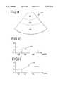
- FIG. 9is a schematic view of a composite image formed with the system of FIG. 8.
- FIGS. 10 and 11are graphs of fundamental and harmonic weighting functions, respectively, suitable for use in forming the image of FIG. 9.
- FIG. 1shows a block diagram of a medical ultrasonic imaging system 10 that provides improved image quality by combining nearfield fundamental, middlefield harmonic, and farfield fundamental images together to create a composite image providing improved resolution throughout the displayed depth.
- the system 10includes a transmit beamformer 12, a transmit/receive switch 14, a phased transducer array 16, a receive beamformer 24, a filter 26, a scan converter 30, and a display 32.
- the transmit beamformer 12generates shaped transmit waveforms so that the transmitted harmonic frequency power is suppressed.
- the receive beamformer 24is operative to form an acoustic beam at either the received fundamental frequency, or at a harmonic of the received fundamental frequency, such as the second harmonic for example.
- the filter 26is adjustable to pass either the fundamental signals or the harmonic signals.
- the scan converter 30is operative to store at least two received acoustic beams and to splice them into a single scan line as described below.
- FIG. 2is a schematic diagram of a composite image 40 formed on the display 32 of FIG. 1.
- the image 40includes five separate regions: a nearfield region 42, a middlefield region 46, a farfield region 50, a nearfield compounded region 44, and a farfield compounded region 48.
- the terms nearfield, middlefield, and farfieldare not intended to define any specific ranges. Rather, these terms define relative ranges, with the nearfield being the closest to the transducer array 16 of FIG. 1.
- the system 10generates a fundamental beam and a harmonic beam along the same azimuthal direction, and then combines the two to form a single scan line with two piece-wise linear weighting functions as shown in FIGS. 3 and 4.
- the fundamental weighting function 60 of FIG. 3has a magnitude of one in the nearfield region 42 and the farfield region 50.
- the function 60decreases linearly from one to zero in the nearfield compounded region 44, and remains at zero in the middlefield region 46 before increasing linearly from zero to one in the farfield compounded region 48.
- the function 60is shown as a linear function in the two compounded regions in FIG. 3, nonlinear functions can also be used.
- the harmonic weighting function 62 of FIG. 4is formed by subtracting the function 60 from 1, such that the sum of the two weighting functions 60, 62 is equal to 1 at any depth.
- the fundamental and harmonic beamsare combined in the scan converter by multiplying the fundamental beam by the fundamental weighting function 60 of FIG. 3, multiplying the harmonic beam by the harmonic weighting function 62 of FIG. 4, and then summing the weighted fundamental and harmonic beams to create a composite beam that is used for display purposes.
- the system 10is operated to acquire a first fundamental beam having a nearfield transmit focus, a harmonic beam having a middlefield transmit focus, and a second fundamental beam having a farfield transmit focus. These three acquired beams are then combined to produce a composite beam. The combination is performed using the harmonic weighting function 62 of FIG. 4 for the harmonic beam.
- the first, nearfield fundamental beamis weighted with the fundamental weighting function 70 of FIG. 5
- the second, farfield fundamental beamis weighted with the fundamental weighting function 72 of FIG. 6.
- the weighted first and second fundamental and harmonic beamsare then added together to create the composite beam that is displayed.
- the first step in this methodis to acquire the required image signals.
- the first image signal F1is a fundamental mode image signal acquired with a nearfield transmit focus.
- the second image signal His a harmonic mode image signal acquired with a middlefield transmit focus.
- the third image signal F2is a second fundamental mode image signal acquired with a farfield transmit focus.
- the next step 78 in the method of FIG. 7is a combining step which includes two component parts.
- the three image signals F1, H and F2 acquired in step 76are weighted or multiplied by weighting functions 70, 62, and 72, respectively, as shown in FIGS. 5, 4 and 6.
- the final portion of the combining step 78is to sum the weighted image signals F1, H and F2 to form the composite image signal that is displayed.
- the methodis then continued with the next set of image signals as appropriate to obtain the composite image signal for the next scan direction.
- the acquiring step 76is performed by the elements 12 through 26 of FIG. 1, and the combining step 78 of FIG. 7 is performed by the scan converter 30 of FIG. 1.
- FIG. 8is a block diagram of another ultrasonic imaging system 80 that can be used to practice alternative embodiments of this invention.
- the system 80includes a transmit beamformer 12, a transmitreceive switch 14, and a transducer array 16 as described above.
- the system 80includes two separate receive beamformers 86, 88.
- the receive beamformer 86forms a receive beam at the fundamental frequency F 0
- the receive beamformer 88forms a receive beam at a second harmonic frequency 2F 0 .
- the fundamental and harmonic receive beamsare applied to filters 90, 92, respectively, before they are combined in the scan converter 94.
- the combined signalis then supplied for display on the display 32. Because both the fundamental and the receive beams are acquired from the same transmit event, the system 80 improves frame rates and reduces motion artifacts as compared to the system 10 of FIG. 1.
- a composite image 100such as that shown in FIG. 9 can be used.
- the image 100is divided into three regions; a nearfield region 102, a farfield region 106, and a compounded region 104.
- the terms nearfield and farfieldare not intended to define any specific ranges, but are instead intended to define relative ranges, with the nearfield being closer to the transducer array 16 than the farfield.
- the imaging systems 10 and 80 of FIGS. 1 and 8can both be used to generate the composite image 100 of FIG. 9.
- the piecewise linear fundamental weighting function 110 (FIG. 10) and harmonic weighting function 112 (FIG. 11)can be used to weight the nearfield fundamental data and the farfield harmonic data, respectively.
- nonlinear weighting functionscan be used if desired.
- the method performed by the imaging system 80 of FIG. 8includes acquiring and combining steps similar to those of FIG. 7, except in this case only a single fundamental mode image signal with a nearfield transmit focus and a single harmonic image mode image signal with a farfield transmit focus are obtained along each azimuthal direction.
- the elements 12 through 14 and 86 through 92perform the acquiring step, and the scan converter 94 performs the combining step.
- the embodiments described aboveprovide the advantages of improved nearfield imaging performance. This improvement in nearfield imaging performance results in an overall image quality that is improved and preserved throughout the imaging depth in technically difficult examinations.
- harmonic and fundamental mode image signalscan be acquired using the widest variety of filtering and demodulation techniques.
- Transmit focal lengthcan be varied as desired, and both single and multiple transmit focus techniques can be used.
- the multiple image signals combined to form the composite image signalcan be obtained in parallel or sequentially.
- Various beamformers, filters and the likecan be used, including those employing analog and digital signal processing techniques.
- the image signalscan be combined to form the composite image signal using many techniques, including look up tables and analog or digital circuits for scaling and summing signals.
- the combining stepcan be performed at any desired point in image signal processing after beam formation, and the compounded regions discussed above are not required in all applications.
- This inventioncan be used both with and without the addition of nonlinear contrast agent to the region being imaged.
- contrast agentWhen contrast agent is added, it can be of any suitable type, including a variety of microbubbles. Particular advantages are obtained when no contrast agent is added to the region of interest throughout the imaging session, which may correspond to a medical diagnostic examination. In this case, the harmonic signal return from the nearfield portion of the imaged region is particularly weak, and improved nearfield images are obtained by using the fundamental image signal for the nearfield region as discussed above.
- fundamental and harmonic mode image signalsare intended broadly. Fundamental mode image signals are formed primarily in response to ultrasonic echoes at the same ultrasonic frequency as the dominant transmitted ultrasonic frequency. Harmonic mode ultrasonic image signals are formed primarily in response to ultrasonic echoes having a frequency different from that of the dominant transmitted ultrasonic frequency.
- harmonicis intended broadly to encompass subharmonics, fractional harmonics, and integral harmonics of two or greater. Second harmonic image modes have been found to be particularly useful in clinical applications.
- farfieldis intended to signify a portion of the imaged tissue farther from the transducer than middlefield, which is in turn farther from the transducer than nearfield.
- the absolute rangesmay vary broadly.
- an imaged regionis said to be modulated primarily as a function of a fundamental or a harmonic image signal, the term primarily is intended broadly to include image regions that are modulated solely as a function of the respective harmonic or fundamental signals.
Landscapes
- Engineering & Computer Science (AREA)
- Physics & Mathematics (AREA)
- Computer Networks & Wireless Communication (AREA)
- General Physics & Mathematics (AREA)
- Radar, Positioning & Navigation (AREA)
- Remote Sensing (AREA)
- Nonlinear Science (AREA)
- Ultra Sonic Daignosis Equipment (AREA)
Abstract
Description
Claims (28)
Priority Applications (1)
| Application Number | Priority Date | Filing Date | Title |
|---|---|---|---|
| US08/993,947US5897500A (en) | 1997-12-18 | 1997-12-18 | Ultrasonic imaging system and method for displaying composite fundamental and harmonic images |
Applications Claiming Priority (1)
| Application Number | Priority Date | Filing Date | Title |
|---|---|---|---|
| US08/993,947US5897500A (en) | 1997-12-18 | 1997-12-18 | Ultrasonic imaging system and method for displaying composite fundamental and harmonic images |
Publications (1)
| Publication Number | Publication Date |
|---|---|
| US5897500Atrue US5897500A (en) | 1999-04-27 |
Family
ID=25540119
Family Applications (1)
| Application Number | Title | Priority Date | Filing Date |
|---|---|---|---|
| US08/993,947Expired - LifetimeUS5897500A (en) | 1997-12-18 | 1997-12-18 | Ultrasonic imaging system and method for displaying composite fundamental and harmonic images |
Country Status (1)
| Country | Link |
|---|---|
| US (1) | US5897500A (en) |
Cited By (25)
| Publication number | Priority date | Publication date | Assignee | Title |
|---|---|---|---|---|
| US5961463A (en)* | 1998-08-24 | 1999-10-05 | General Electric Company | Nonlinear imaging using orthogonal transmit and receive codes |
| US6001062A (en)* | 1998-08-03 | 1999-12-14 | Scimed Life Systems, Inc. | Slewing bandpass filter for selective passage of time varying acoustic signals |
| US6036643A (en)* | 1998-05-14 | 2000-03-14 | Advanced Technology Laboratories, Inc. | Ultrasonic harmonic doppler imaging |
| US6048316A (en)* | 1998-10-16 | 2000-04-11 | Acuson Corporation | Medical diagnostic ultrasonic imaging system and method for displaying composite fundamental and harmonic images |
| US6117082A (en)* | 1999-03-31 | 2000-09-12 | Acuson Corporation | Medical diagnostic ultrasound imaging system and method with fractional harmonic seed signal |
| US6132374A (en)* | 1997-08-01 | 2000-10-17 | Acuson Corporation | Ultrasonic imaging method and system |
| US6146330A (en)* | 1998-04-10 | 2000-11-14 | Kabushiki Kaisha Toshiba | Ultrasound diagnosis apparatus for generating an image based on extracted harmonics component |
| US6206833B1 (en) | 1996-11-08 | 2001-03-27 | Research Corporation Technologiers, Inc. | Finite amplitude distortion-based inhomogeneous pulse echo ultrasonic imaging |
| US6283919B1 (en)* | 1996-11-26 | 2001-09-04 | Atl Ultrasound | Ultrasonic diagnostic imaging with blended tissue harmonic signals |
| US6438258B1 (en)* | 1998-01-23 | 2002-08-20 | Koninklijke Philips Electronics N.V. | Ultrasound image processing employing non-linear tissue response backscatter signals |
| US6440075B1 (en) | 2000-10-02 | 2002-08-27 | Koninklijke Philips Electronics N.V. | Ultrasonic diagnostic imaging of nonlinearly intermodulated and harmonic frequency components |
| US6458083B1 (en) | 1996-11-26 | 2002-10-01 | Koninklijke Philips Electronics N.V. | Ultrasonic harmonic imaging with adaptive image formation |
| US6514206B2 (en) | 2001-03-09 | 2003-02-04 | Koninklijke Philips Electronics, N.V. | Simultaneous fundamental and harmonic ultrasonic imaging |
| US6540683B1 (en)* | 2001-09-14 | 2003-04-01 | Gregory Sharat Lin | Dual-frequency ultrasonic array transducer and method of harmonic imaging |
| US6626836B2 (en) | 2001-04-04 | 2003-09-30 | Siemens Medical Solutions Usa, Inc. | Adaptive signal processing scheme for contrast agent imaging |
| US20040064043A1 (en)* | 2002-09-30 | 2004-04-01 | Koninklijke Philips Electronics N.V. | Continuous depth harmonic imaging using transmitted and nonlinearly generated second harmonics |
| US20040087856A1 (en)* | 2002-11-01 | 2004-05-06 | Satchi Panda | Method and apparatus for B-mode image banding suppression |
| US20060266466A1 (en)* | 2005-05-31 | 2006-11-30 | Curt G. Joa, Inc. | Web stabilization on a slip and cut applicator |
| CN1297235C (en)* | 2001-05-31 | 2007-01-31 | 诺华索尼克斯有限公司 | Phase-changing supersonic imaging system and method |
| US20090024031A1 (en)* | 2007-07-18 | 2009-01-22 | Kabushiki Kaisha Toshiba | Ultrasonic diagnostic apparatus and ultrasonic diagnostic method |
| CN103431873A (en)* | 2013-03-08 | 2013-12-11 | 无锡祥生医学影像有限责任公司 | Ultrasonic fuse harmonic imaging system and method |
| USRE44708E1 (en)* | 1996-09-27 | 2014-01-14 | Philips Ultrasound, Inc. | Ultrasonic diagnostic imaging with blended tissue harmonic signals |
| US20180000452A1 (en)* | 2015-01-29 | 2018-01-04 | Koninklijke Philips N.V. | Broadband blended fundamental and harmonic frequency ultrasonic diagnostic imaging |
| CN112294354A (en)* | 2019-08-02 | 2021-02-02 | 深圳迈瑞生物医疗电子股份有限公司 | Ultrasound imaging method and system |
| CN115702803A (en)* | 2021-08-10 | 2023-02-17 | 青岛海信医疗设备股份有限公司 | An ultrasonic device and an ultrasonic attenuation imaging method |
Citations (53)
| Publication number | Priority date | Publication date | Assignee | Title |
|---|---|---|---|---|
| US3640271A (en)* | 1969-06-30 | 1972-02-08 | Ibm | Blood flow pressure measurement technique employing injected bubbled and ultrasonic frequency scanning |
| US4712037A (en)* | 1985-07-03 | 1987-12-08 | Nederlandse Centrale Organisatie Voor Toegepast-Natuurwetenschappelijk Onderzoek | Resonant piezoelectric sensor |
| EP0357164A1 (en)* | 1988-09-01 | 1990-03-07 | Schering Aktiengesellschaft | Ultrasonic method and circuitries for carrying out same |
| US5111823A (en)* | 1989-04-20 | 1992-05-12 | National Fertility Institute | Apparatus and method for generating echographic images |
| US5115809A (en)* | 1989-03-31 | 1992-05-26 | Kabushiki Kaisha Toshiba | Ultrasonic probe |
| US5135000A (en)* | 1990-09-19 | 1992-08-04 | Raizot University Authority For Applied Research & Industrial Development Ltd. | Method of measuring regional tissue blood flow |
| US5158071A (en)* | 1988-07-01 | 1992-10-27 | Hitachi, Ltd. | Ultrasonic apparatus for therapeutical use |
| US5195520A (en)* | 1986-11-05 | 1993-03-23 | Schering Aktiengesellschaft | Ultrasonic manometry process in a fluid by means of microbubbles |
| US5197477A (en)* | 1990-10-12 | 1993-03-30 | Advanced Technology Laboratories, Inc. | Ultrasonic doppler flow measurement system with tissue motion discrimination |
| US5233994A (en)* | 1991-05-13 | 1993-08-10 | Advanced Technology Laboratories, Inc. | Detection of tissue abnormality through blood perfusion differentiation |
| US5255683A (en)* | 1991-12-30 | 1993-10-26 | Sound Science Limited Partnership | Methods of and systems for examining tissue perfusion using ultrasonic contrast agents |
| US5287753A (en)* | 1992-05-02 | 1994-02-22 | Advanced Technology Laboratories, Inc. | Continuous display of peak and mean blood flow velocities |
| US5313948A (en)* | 1991-11-28 | 1994-05-24 | Aloka Co., Ltd. | Ultrasonic diagnostic apparatus |
| US5358466A (en)* | 1991-04-15 | 1994-10-25 | Kabushiki Kaisha Toshiba | Apparatus for destroying a calculus |
| US5386830A (en)* | 1993-10-25 | 1995-02-07 | Advanced Technology Laboratories, Inc. | Ultrasonic pulsed doppler flow measurement system with two dimensional autocorrelation processing |
| US5396285A (en)* | 1993-05-07 | 1995-03-07 | Acuson Corporation | Ultrasound imaging method and apparatus with dynamic non-linear filtering |
| US5410205A (en)* | 1993-02-11 | 1995-04-25 | Hewlett-Packard Company | Ultrasonic transducer having two or more resonance frequencies |
| US5410516A (en)* | 1988-09-01 | 1995-04-25 | Schering Aktiengesellschaft | Ultrasonic processes and circuits for performing them |
| US5409688A (en)* | 1991-09-17 | 1995-04-25 | Sonus Pharmaceuticals, Inc. | Gaseous ultrasound contrast media |
| US5417214A (en)* | 1992-08-07 | 1995-05-23 | Trustees Of The University Of Pennsylvania | Quantitative blood flow measurement using steady-state transport-induced adiabatic fast passage |
| US5417213A (en)* | 1993-06-07 | 1995-05-23 | Prince; Martin R. | Magnetic resonance arteriography with dynamic intravenous contrast agents |
| US5425366A (en)* | 1988-02-05 | 1995-06-20 | Schering Aktiengesellschaft | Ultrasonic contrast agents for color Doppler imaging |
| US5433204A (en)* | 1993-11-16 | 1995-07-18 | Camilla Olson | Method of assessing placentation |
| US5433207A (en)* | 1993-11-15 | 1995-07-18 | Pretlow, Iii; Robert A. | Method and apparatus to characterize ultrasonically reflective contrast agents |
| US5435311A (en)* | 1989-06-27 | 1995-07-25 | Hitachi, Ltd. | Ultrasound therapeutic system |
| US5438554A (en)* | 1993-06-15 | 1995-08-01 | Hewlett-Packard Company | Tunable acoustic resonator for clinical ultrasonic transducers |
| US5443071A (en)* | 1994-10-11 | 1995-08-22 | Siemens Medical Systems, Inc. | Quantitative color flow |
| US5456257A (en)* | 1994-11-23 | 1995-10-10 | Advanced Technology Laboratories, Inc. | Ultrasonic detection of contrast agents |
| US5456255A (en)* | 1993-07-12 | 1995-10-10 | Kabushiki Kaisha Toshiba | Ultrasonic diagnosis apparatus |
| US5462057A (en)* | 1994-06-06 | 1995-10-31 | Hewlett-Packard Company | Ultrasound imaging system using line splicing and parallel receive beam formation |
| US5469849A (en)* | 1993-06-14 | 1995-11-28 | Kabushiki Kaisha Toshiba | Ultrasound diagnosis apparatus |
| US5471990A (en)* | 1994-11-23 | 1995-12-05 | Advanced Technology Laboratories, Inc. | Ultrasonic doppler power measurement and display system |
| US5479926A (en)* | 1995-03-10 | 1996-01-02 | Acuson Corporation | Imaging system display processor |
| US5482046A (en)* | 1994-11-23 | 1996-01-09 | General Electric Company | Acoustic power control technique |
| US5526816A (en)* | 1994-09-22 | 1996-06-18 | Bracco Research S.A. | Ultrasonic spectral contrast imaging |
| US5540909A (en)* | 1994-09-28 | 1996-07-30 | Alliance Pharmaceutical Corp. | Harmonic ultrasound imaging with microbubbles |
| US5558092A (en)* | 1995-06-06 | 1996-09-24 | Imarx Pharmaceutical Corp. | Methods and apparatus for performing diagnostic and therapeutic ultrasound simultaneously |
| US5560364A (en)* | 1995-05-12 | 1996-10-01 | The Board Of Regents Of The University Of Nebraska | Suspended ultra-sound induced microbubble cavitation imaging |
| US5568813A (en)* | 1994-11-23 | 1996-10-29 | General Electric Company | Method for combining ultrasound vector data from multiple firings to improve image quality |
| US5577505A (en)* | 1996-02-06 | 1996-11-26 | Hewlett-Packard Company | Means for increasing sensitivity in non-linear ultrasound imaging systems |
| US5579770A (en)* | 1995-05-02 | 1996-12-03 | Acuson Corporation | Multiple transmit zone splicing |
| US5579768A (en)* | 1995-03-21 | 1996-12-03 | Acuson Corporation | Automatic gain compensation in an ultrasound imaging system |
| US5588435A (en)* | 1995-11-22 | 1996-12-31 | Siemens Medical Systems, Inc. | System and method for automatic measurement of body structures |
| US5601085A (en)* | 1995-10-02 | 1997-02-11 | Nycomed Imaging As | Ultrasound imaging |
| US5601086A (en)* | 1995-05-12 | 1997-02-11 | The United States Of America As Represented By The Administrator Of The National Aeronautics And Space Administration | Beat frequency ultrasonic microsphere contrast agent detection system |
| US5608690A (en)* | 1995-03-02 | 1997-03-04 | Acuson Corporation | Transmit beamformer with frequency dependent focus |
| US5617862A (en)* | 1995-05-02 | 1997-04-08 | Acuson Corporation | Method and apparatus for beamformer system with variable aperture |
| EP0770352A1 (en)* | 1995-10-10 | 1997-05-02 | Advanced Technology Laboratories, Inc. | Ultrasonic diagnostic imaging with contrast agents |
| US5628322A (en)* | 1995-05-15 | 1997-05-13 | Kabushiki Kaisha Toshiba | Method of ultrasound imaging and diagnostic ultrasound system |
| US5632277A (en)* | 1996-06-28 | 1997-05-27 | Siemens Medical Systems, Inc. | Ultrasound imaging system employing phase inversion subtraction to enhance the image |
| US5724976A (en)* | 1994-12-28 | 1998-03-10 | Kabushiki Kaisha Toshiba | Ultrasound imaging preferable to ultrasound contrast echography |
| WO1998020361A1 (en)* | 1996-11-08 | 1998-05-14 | Research Corporation Technologies, Inc. | Finite amplitude distortion-based inhomogeneous pulse echo ultrasonic imaging |
| EP0851241A2 (en)* | 1996-11-26 | 1998-07-01 | ATL Ultrasound, Inc. | Ultrasonic diagnostic imaging of response frequency differing from transmit frequency |
- 1997
- 1997-12-18USUS08/993,947patent/US5897500A/ennot_activeExpired - Lifetime
Patent Citations (54)
| Publication number | Priority date | Publication date | Assignee | Title |
|---|---|---|---|---|
| US3640271A (en)* | 1969-06-30 | 1972-02-08 | Ibm | Blood flow pressure measurement technique employing injected bubbled and ultrasonic frequency scanning |
| US4712037A (en)* | 1985-07-03 | 1987-12-08 | Nederlandse Centrale Organisatie Voor Toegepast-Natuurwetenschappelijk Onderzoek | Resonant piezoelectric sensor |
| US5195520A (en)* | 1986-11-05 | 1993-03-23 | Schering Aktiengesellschaft | Ultrasonic manometry process in a fluid by means of microbubbles |
| US5425366A (en)* | 1988-02-05 | 1995-06-20 | Schering Aktiengesellschaft | Ultrasonic contrast agents for color Doppler imaging |
| US5158071A (en)* | 1988-07-01 | 1992-10-27 | Hitachi, Ltd. | Ultrasonic apparatus for therapeutical use |
| EP0357164A1 (en)* | 1988-09-01 | 1990-03-07 | Schering Aktiengesellschaft | Ultrasonic method and circuitries for carrying out same |
| US5410516A (en)* | 1988-09-01 | 1995-04-25 | Schering Aktiengesellschaft | Ultrasonic processes and circuits for performing them |
| US5115809A (en)* | 1989-03-31 | 1992-05-26 | Kabushiki Kaisha Toshiba | Ultrasonic probe |
| US5111823A (en)* | 1989-04-20 | 1992-05-12 | National Fertility Institute | Apparatus and method for generating echographic images |
| US5435311A (en)* | 1989-06-27 | 1995-07-25 | Hitachi, Ltd. | Ultrasound therapeutic system |
| US5135000A (en)* | 1990-09-19 | 1992-08-04 | Raizot University Authority For Applied Research & Industrial Development Ltd. | Method of measuring regional tissue blood flow |
| US5197477A (en)* | 1990-10-12 | 1993-03-30 | Advanced Technology Laboratories, Inc. | Ultrasonic doppler flow measurement system with tissue motion discrimination |
| US5358466A (en)* | 1991-04-15 | 1994-10-25 | Kabushiki Kaisha Toshiba | Apparatus for destroying a calculus |
| US5233994A (en)* | 1991-05-13 | 1993-08-10 | Advanced Technology Laboratories, Inc. | Detection of tissue abnormality through blood perfusion differentiation |
| US5409688A (en)* | 1991-09-17 | 1995-04-25 | Sonus Pharmaceuticals, Inc. | Gaseous ultrasound contrast media |
| US5313948A (en)* | 1991-11-28 | 1994-05-24 | Aloka Co., Ltd. | Ultrasonic diagnostic apparatus |
| US5255683A (en)* | 1991-12-30 | 1993-10-26 | Sound Science Limited Partnership | Methods of and systems for examining tissue perfusion using ultrasonic contrast agents |
| US5287753A (en)* | 1992-05-02 | 1994-02-22 | Advanced Technology Laboratories, Inc. | Continuous display of peak and mean blood flow velocities |
| US5417214A (en)* | 1992-08-07 | 1995-05-23 | Trustees Of The University Of Pennsylvania | Quantitative blood flow measurement using steady-state transport-induced adiabatic fast passage |
| US5410205A (en)* | 1993-02-11 | 1995-04-25 | Hewlett-Packard Company | Ultrasonic transducer having two or more resonance frequencies |
| US5396285A (en)* | 1993-05-07 | 1995-03-07 | Acuson Corporation | Ultrasound imaging method and apparatus with dynamic non-linear filtering |
| US5417213A (en)* | 1993-06-07 | 1995-05-23 | Prince; Martin R. | Magnetic resonance arteriography with dynamic intravenous contrast agents |
| US5469849A (en)* | 1993-06-14 | 1995-11-28 | Kabushiki Kaisha Toshiba | Ultrasound diagnosis apparatus |
| US5438554A (en)* | 1993-06-15 | 1995-08-01 | Hewlett-Packard Company | Tunable acoustic resonator for clinical ultrasonic transducers |
| US5456255A (en)* | 1993-07-12 | 1995-10-10 | Kabushiki Kaisha Toshiba | Ultrasonic diagnosis apparatus |
| US5386830A (en)* | 1993-10-25 | 1995-02-07 | Advanced Technology Laboratories, Inc. | Ultrasonic pulsed doppler flow measurement system with two dimensional autocorrelation processing |
| US5433207A (en)* | 1993-11-15 | 1995-07-18 | Pretlow, Iii; Robert A. | Method and apparatus to characterize ultrasonically reflective contrast agents |
| US5433204A (en)* | 1993-11-16 | 1995-07-18 | Camilla Olson | Method of assessing placentation |
| US5462057A (en)* | 1994-06-06 | 1995-10-31 | Hewlett-Packard Company | Ultrasound imaging system using line splicing and parallel receive beam formation |
| US5526816A (en)* | 1994-09-22 | 1996-06-18 | Bracco Research S.A. | Ultrasonic spectral contrast imaging |
| US5540909A (en)* | 1994-09-28 | 1996-07-30 | Alliance Pharmaceutical Corp. | Harmonic ultrasound imaging with microbubbles |
| US5443071A (en)* | 1994-10-11 | 1995-08-22 | Siemens Medical Systems, Inc. | Quantitative color flow |
| US5482046A (en)* | 1994-11-23 | 1996-01-09 | General Electric Company | Acoustic power control technique |
| US5471990A (en)* | 1994-11-23 | 1995-12-05 | Advanced Technology Laboratories, Inc. | Ultrasonic doppler power measurement and display system |
| US5456257A (en)* | 1994-11-23 | 1995-10-10 | Advanced Technology Laboratories, Inc. | Ultrasonic detection of contrast agents |
| US5568813A (en)* | 1994-11-23 | 1996-10-29 | General Electric Company | Method for combining ultrasound vector data from multiple firings to improve image quality |
| US5724976A (en)* | 1994-12-28 | 1998-03-10 | Kabushiki Kaisha Toshiba | Ultrasound imaging preferable to ultrasound contrast echography |
| US5608690A (en)* | 1995-03-02 | 1997-03-04 | Acuson Corporation | Transmit beamformer with frequency dependent focus |
| US5740128A (en)* | 1995-03-02 | 1998-04-14 | Acuson Corporation | Ultrasonic harmonic imaging system and method |
| US5479926A (en)* | 1995-03-10 | 1996-01-02 | Acuson Corporation | Imaging system display processor |
| US5579768A (en)* | 1995-03-21 | 1996-12-03 | Acuson Corporation | Automatic gain compensation in an ultrasound imaging system |
| US5617862A (en)* | 1995-05-02 | 1997-04-08 | Acuson Corporation | Method and apparatus for beamformer system with variable aperture |
| US5579770A (en)* | 1995-05-02 | 1996-12-03 | Acuson Corporation | Multiple transmit zone splicing |
| US5601086A (en)* | 1995-05-12 | 1997-02-11 | The United States Of America As Represented By The Administrator Of The National Aeronautics And Space Administration | Beat frequency ultrasonic microsphere contrast agent detection system |
| US5560364A (en)* | 1995-05-12 | 1996-10-01 | The Board Of Regents Of The University Of Nebraska | Suspended ultra-sound induced microbubble cavitation imaging |
| US5628322A (en)* | 1995-05-15 | 1997-05-13 | Kabushiki Kaisha Toshiba | Method of ultrasound imaging and diagnostic ultrasound system |
| US5558092A (en)* | 1995-06-06 | 1996-09-24 | Imarx Pharmaceutical Corp. | Methods and apparatus for performing diagnostic and therapeutic ultrasound simultaneously |
| US5601085A (en)* | 1995-10-02 | 1997-02-11 | Nycomed Imaging As | Ultrasound imaging |
| EP0770352A1 (en)* | 1995-10-10 | 1997-05-02 | Advanced Technology Laboratories, Inc. | Ultrasonic diagnostic imaging with contrast agents |
| US5588435A (en)* | 1995-11-22 | 1996-12-31 | Siemens Medical Systems, Inc. | System and method for automatic measurement of body structures |
| US5577505A (en)* | 1996-02-06 | 1996-11-26 | Hewlett-Packard Company | Means for increasing sensitivity in non-linear ultrasound imaging systems |
| US5632277A (en)* | 1996-06-28 | 1997-05-27 | Siemens Medical Systems, Inc. | Ultrasound imaging system employing phase inversion subtraction to enhance the image |
| WO1998020361A1 (en)* | 1996-11-08 | 1998-05-14 | Research Corporation Technologies, Inc. | Finite amplitude distortion-based inhomogeneous pulse echo ultrasonic imaging |
| EP0851241A2 (en)* | 1996-11-26 | 1998-07-01 | ATL Ultrasound, Inc. | Ultrasonic diagnostic imaging of response frequency differing from transmit frequency |
Non-Patent Citations (52)
| Title |
|---|
| "Abstract Session IV Contrast and Ischemia" and "Post Session A New Technologies". Journal of the American Society of Echocardiography, vol. 8, No. 3, May 1995. |
| "HP Ultrasound Technologies--Viability." About HP Ultrasound Imaging, WWW document, 1997. |
| "Supplement to Journal of the American College of Cardiology" American College of Cardiology, 45th Annual Scientific Session, Mar. 24-27, 1996 pp. 21A, 63A, 239-240A. |
| Abstract Session IV Contrast and Ischemia and Post Session A New Technologies . Journal of the American Society of Echocardiography, vol. 8, No. 3, May 1995.* |
| Amir, et al., IEEE UFFC, vol. 33, pp. 402 411, 1986.* |
| Amir, et al., IEEE UFFC, vol. 33, pp. 402-411, 1986. |
| B. Schrope, et al., Simulated Capillary Blood Flow Measurement Using A Nonlinear Ultrasonic Contrast Agent, Ultrasonic Imaging 14 (1992).* |
| Chandra M. Sehgal, PhD, et al., "Influence of Postprocessing Curves on Contrast--Echographic Imaging: Preliminary Studies." J. Ultrasound Med, 14 (1995). |
| Chandra M. Sehgal, PhD, et al., Influence of Postprocessing Curves on Contrast Echographic Imaging: Preliminary Studies. J. Ultrasound Med, 14 (1995).* |
| Chandra M. Sehgal, PhD., et al., Sonographic Enhancement of Renal Cortex by Contrast Media. J. Ultrasound Med, 14 (1995).* |
| Chiang C. Mei, et al., Parametric resonance of a spherical bubble. J. Fluid Mech. (1991) vol. 229.* |
| Deborah J. Rubens, M.D., et al., Sonoelasticity Imaging of Prostate Cancer: In Vitro Results. Radiology, vol. 995, No. 2, 1995.* |
| Eric J. Chen, et al., "Young's Modulus Measurements of Soft Tissues with Application to Elasticity Imaging." IEEE Transactions on Ultrasonics, Ferroelectrics, and Frequency Control, vol. 43, No. 1, Jan. 1996. |
| Eric J. Chen, et al., Young s Modulus Measurements of Soft Tissues with Application to Elasticity Imaging. IEEE Transactions on Ultrasonics, Ferroelectrics, and Frequency Control, vol. 43, No. 1, Jan. 1996.* |
| Fred Lee, Jr., M.D., et al., Sonoelasticity Imaging: Results in in Vitro Tissue Specimens. Radiology, vol. 181, No. 1, 1991.* |
| H. Edward Karrer, et al., A Phased Array Acoustic Imaging System for Medical Use. 1980 Ultrasonics Symposium.* |
| HP Ultrasound Technologies Viability. About HP Ultrasound Imaging, WWW document, 1997.* |
| J. Ophir, et al., Elastography: A Quantitative Method for Imaging the Elasticity of Biological Tissues. Ultrasonics Imaging 13 (1991).* |
| J. W. Norris, "The non-linear oscillation of a radially symmetric bubble in a time periodic pressure field." Dynamics and Stability of Systems, vol. 9, No. 1 (1994). |
| J. W. Norris, The non linear oscillation of a radially symmetric bubble in a time periodic pressure field. Dynamics and Stability of Systems, vol. 9, No. 1 (1994).* |
| J.A. Hossack et al., Improving transducer performance using multiple active layers. SPIE vol. 1733 (1992).* |
| Janet B. Jones Oliveira, et al., Transient fluid solid interaction of submerged spherical shells revisited: Proliferation of frequencies and acoustic radiation effects. Acoustical Society of America, 96(2) Pt. 1, Aug. 1994.* |
| Janet B. Jones-Oliveira, et al., "Transient fluid--solid interaction of submerged spherical shells revisited: Proliferation of frequencies and acoustic radiation effects." Acoustical Society of America, 96(2) Pt. 1, Aug. 1994. |
| John A. Hossack, et al., Improving the Characteristics of a Transducer Using Multiple Piezoelectric Layers. IEEE Transactions on Ultrasonics, Ferroelectrics, and Frequency Control, vol. 40, No. 2, Mar. 1993.* |
| K.J. Parker, et al., "Tissue Response to Mechanical Vibrations for `Sonoelasticity Imaging`." Ultrasound in Med. & Biol., vol. 16, No. 3, (1990). |
| K.J. Parker, et al., Tissue Response to Mechanical Vibrations for Sonoelasticity Imaging . Ultrasound in Med. & Biol., vol. 16, No. 3, (1990).* |
| Ken Ishihara et al., New Approach to Noninvasive Manometry Based on Pressure Dependent Resonant Shift of Elastic Microcapsules in Ultrasonic Frequency Characteristics. Japanese J. of Applied Physics, vol. 2 (1988).* |
| Kevin J. Parker, PhD, et al., Sonoelasticity of Organs: Shear Waves Ring a Bell. J. Ultrasound Med., 11 (1992).* |
| Kotaro Sato, et al., Numerical analysis of a gas bubble near a rigid boundary in an oscillatory pressure field. J. Acoustical Society of America, 95 (5), May 1994.* |
| L.W. Anson et al., Ultrasonic scattering from spherical shells including viscous and thermal effects. J. Acoustical Society of America, 93 (4), Apr. 1993.* |
| Magin, et al., Ultrasonic Imaging, vol. 4, No. 3, pp. 267 281, 1982.* |
| Magin, et al., Ultrasonic Imaging, vol. 4, No. 3, pp. 267-281, 1982. |
| Marc Gensane, Bubble population measurements with a parametric array. 1994 Acoustical Society of America, 95 (6) Jun.* |
| Michael S. Longuet Higgins, Resonance in nonlinear bubble oscillations. J. Fluid Mech. (1991) vol. 224.* |
| Michael S. Longuet-Higgins, Resonance in nonlinear bubble oscillations. J. Fluid Mech. (1991) vol. 224. |
| Michalakis A. Averkious, et al., "Self-demodulation of amplitude-and frequency-modulated pulses in a thermoviscous fluid." J. Acoustical Society of America, 94 (5), Nov. 1993. |
| Michalakis A. Averkious, et al., Self demodulation of amplitude and frequency modulated pulses in a thermoviscous fluid. J. Acoustical Society of America, 94 (5), Nov. 1993.* |
| Nico de Jong, Physical properties and technical aspects of ultrasound contrast agents. (one page).* |
| Pi Hsien Chang, et al., Second Harmonic Imaging and Harmonic Doppler Measurements with Albunex. IEEE Transactions on Ultrasonics, Ferroelectrics, and Frequency Control, vol. 42, No. 6, Nov. 1996.* |
| Robert M. Lerner, et al., "`Sonoelasticity`+Images Derived from Ultrasound Signals in Mechanically Vibrated Tissues." Ultrasound in Med. & Biol., vol. 16, No. 3, (1990). |
| Robert M. Lerner, et al., Sonoelasticity Images Derived from Ultrasound Signals in Mechanically Vibrated Tissues. Ultrasound in Med. & Biol., vol. 16, No. 3, (1990).* |
| Shmuel Gottlieb, M.D. et al., Effect of Pressure on Echocardiographic Videodensity from Sonicated Albumin: An In Vitro Model. J. Ultrasound Med. 14 (1995).* |
| Supplement to Journal of the American College of Cardiology American College of Cardiology, 45 th Annual Scientific Session, Mar. 24 27, 1996 pp. 21A, 63A, 239 240A.* |
| T.G. Leighton, Transient excitation of insonated bubbles. Research Notes.* |
| Ted Christopher, "Finite Amplitude Distortion-Based Inhomogeneous Pulse Echo Ultrasonic Imaging." IEEE Transactions on Ultrasonics, Ferroelectrics, and Frequency Control, vol. 44, No. 1, Jan. 1997. |
| Ted Christopher, Finite Amplitude Distortion Based Inhomogeneous Pulse Echo Ultrasonic Imaging. IEEE Transactions on Ultrasonics, Ferroelectrics, and Frequency Control, vol. 44, No. 1, Jan. 1997.* |
| V.L. Newhouse, et al., Bubble size measurements using the nonlinear mixing of two frequencies. J. Acoust. Soc. Am. 75 (5), May 1984.* |
| Volkmar Uhlendorf, et al., Nonlinear Acoustical Response of Coated Microbubbles in Diagnostic Ultrasound. 1994 Ultrasonics Symposium.* |
| William Armstrong, M.D., et al., "American Society of Echocardiography Position Paper on Contrast Echocardiography." draft 1--Jun. 6, 1994. |
| William Armstrong, M.D., et al., American Society of Echocardiography Position Paper on Contrast Echocardiography. draft 1 Jun. 6, 1994.* |
| Yang Sub Lee, et al., Time domain modeling of pulsed finite amplitude sound beams. 1995 Acoustical Society of America, 97 (2), Feb. 1995.* |
| Yang-Sub Lee, et al., "Time-domain modeling of pulsed finite-amplitude sound beams." 1995 Acoustical Society of America, 97 (2), Feb. 1995. |
Cited By (42)
| Publication number | Priority date | Publication date | Assignee | Title |
|---|---|---|---|---|
| US8454516B1 (en) | 1996-09-27 | 2013-06-04 | Philips Ultrasound, Inc. | System and method for three dimensional harmonic ultrasound imaging |
| USRE44708E1 (en)* | 1996-09-27 | 2014-01-14 | Philips Ultrasound, Inc. | Ultrasonic diagnostic imaging with blended tissue harmonic signals |
| US7513870B2 (en) | 1996-11-08 | 2009-04-07 | Research Corproation Technologies, Inc. | Finite amplitude distortion-based inhomogeneous pulse echo ultrasonic imaging |
| US7811233B2 (en) | 1996-11-08 | 2010-10-12 | Research Corporation Technologies, Inc. | Finite amplitude distortion-based inhomogeneous pulse echo ultrasonic imaging |
| US20090105591A1 (en)* | 1996-11-08 | 2009-04-23 | Research Corporation Technologies, Inc. | Finite amplitude distortion-based inhomogeneous pulse echo ultrasonic imaging |
| US20040249280A1 (en)* | 1996-11-08 | 2004-12-09 | Research Corporation Technologies, Inc. | Finite amplitude distortion-based inhomogeneous pulse echo ultrasonic imaging |
| US6206833B1 (en) | 1996-11-08 | 2001-03-27 | Research Corporation Technologiers, Inc. | Finite amplitude distortion-based inhomogeneous pulse echo ultrasonic imaging |
| US20060241433A1 (en)* | 1996-11-08 | 2006-10-26 | Research Technologies, Inc. | Finite amplitude distortion-based inhomogeneous pulse echo ultrasonic imaging |
| US7104956B1 (en) | 1996-11-08 | 2006-09-12 | Research Corporation Technologies, Inc. | Finite amplitude distortion-based inhomogeneous pulse echo ultrasonic imaging |
| US7004905B2 (en) | 1996-11-08 | 2006-02-28 | Research Corporation Technologies, Inc. | Finite amplitude distortion-based inhomogeneous pulse echo ultrasonic imaging |
| US20050033180A1 (en)* | 1996-11-08 | 2005-02-10 | Research Corporation Technologies, Inc. | Finite amplitude distortion-based inhomogeneous pulse echo ultrasonic imaging |
| US6283919B1 (en)* | 1996-11-26 | 2001-09-04 | Atl Ultrasound | Ultrasonic diagnostic imaging with blended tissue harmonic signals |
| US6458083B1 (en) | 1996-11-26 | 2002-10-01 | Koninklijke Philips Electronics N.V. | Ultrasonic harmonic imaging with adaptive image formation |
| US6132374A (en)* | 1997-08-01 | 2000-10-17 | Acuson Corporation | Ultrasonic imaging method and system |
| US6438258B1 (en)* | 1998-01-23 | 2002-08-20 | Koninklijke Philips Electronics N.V. | Ultrasound image processing employing non-linear tissue response backscatter signals |
| US6146330A (en)* | 1998-04-10 | 2000-11-14 | Kabushiki Kaisha Toshiba | Ultrasound diagnosis apparatus for generating an image based on extracted harmonics component |
| US6036643A (en)* | 1998-05-14 | 2000-03-14 | Advanced Technology Laboratories, Inc. | Ultrasonic harmonic doppler imaging |
| US6001062A (en)* | 1998-08-03 | 1999-12-14 | Scimed Life Systems, Inc. | Slewing bandpass filter for selective passage of time varying acoustic signals |
| US6315725B1 (en) | 1998-08-03 | 2001-11-13 | Scimed Life Systems, Inc. | Slewing bandpass filter for ultrasound image analysis and methods |
| US5961463A (en)* | 1998-08-24 | 1999-10-05 | General Electric Company | Nonlinear imaging using orthogonal transmit and receive codes |
| US6048316A (en)* | 1998-10-16 | 2000-04-11 | Acuson Corporation | Medical diagnostic ultrasonic imaging system and method for displaying composite fundamental and harmonic images |
| US6117082A (en)* | 1999-03-31 | 2000-09-12 | Acuson Corporation | Medical diagnostic ultrasound imaging system and method with fractional harmonic seed signal |
| US6440075B1 (en) | 2000-10-02 | 2002-08-27 | Koninklijke Philips Electronics N.V. | Ultrasonic diagnostic imaging of nonlinearly intermodulated and harmonic frequency components |
| US6514206B2 (en) | 2001-03-09 | 2003-02-04 | Koninklijke Philips Electronics, N.V. | Simultaneous fundamental and harmonic ultrasonic imaging |
| US6626836B2 (en) | 2001-04-04 | 2003-09-30 | Siemens Medical Solutions Usa, Inc. | Adaptive signal processing scheme for contrast agent imaging |
| CN1297235C (en)* | 2001-05-31 | 2007-01-31 | 诺华索尼克斯有限公司 | Phase-changing supersonic imaging system and method |
| US6540683B1 (en)* | 2001-09-14 | 2003-04-01 | Gregory Sharat Lin | Dual-frequency ultrasonic array transducer and method of harmonic imaging |
| US20040064043A1 (en)* | 2002-09-30 | 2004-04-01 | Koninklijke Philips Electronics N.V. | Continuous depth harmonic imaging using transmitted and nonlinearly generated second harmonics |
| US7056290B2 (en)* | 2002-09-30 | 2006-06-06 | Koninklijke Philips Electronics, N.V. | Continuous depth harmonic imaging using transmitted and nonlinearly generated second harmonics |
| US6893399B2 (en)* | 2002-11-01 | 2005-05-17 | Ge Medical Systems Global Technology Company, Llc | Method and apparatus for B-mode image banding suppression |
| US20040087856A1 (en)* | 2002-11-01 | 2004-05-06 | Satchi Panda | Method and apparatus for B-mode image banding suppression |
| US20060266466A1 (en)* | 2005-05-31 | 2006-11-30 | Curt G. Joa, Inc. | Web stabilization on a slip and cut applicator |
| US20090024031A1 (en)* | 2007-07-18 | 2009-01-22 | Kabushiki Kaisha Toshiba | Ultrasonic diagnostic apparatus and ultrasonic diagnostic method |
| CN103431873A (en)* | 2013-03-08 | 2013-12-11 | 无锡祥生医学影像有限责任公司 | Ultrasonic fuse harmonic imaging system and method |
| CN103431873B (en)* | 2013-03-08 | 2015-07-15 | 无锡祥生医学影像有限责任公司 | Ultrasonic fuse harmonic imaging system and method |
| US9274215B2 (en) | 2013-03-08 | 2016-03-01 | Chison Medical Imaging, Inc. | Ultrasound fusion harmonic imaging systems and methods |
| US20180000452A1 (en)* | 2015-01-29 | 2018-01-04 | Koninklijke Philips N.V. | Broadband blended fundamental and harmonic frequency ultrasonic diagnostic imaging |
| US10952703B2 (en)* | 2015-01-29 | 2021-03-23 | Koninklijke Philips N.V. | Broadband blended fundamental and harmonic frequency ultrasonic diagnostic imaging |
| CN112294354A (en)* | 2019-08-02 | 2021-02-02 | 深圳迈瑞生物医疗电子股份有限公司 | Ultrasound imaging method and system |
| CN112294354B (en)* | 2019-08-02 | 2024-06-11 | 深圳迈瑞生物医疗电子股份有限公司 | Ultrasound imaging method and system |
| CN115702803A (en)* | 2021-08-10 | 2023-02-17 | 青岛海信医疗设备股份有限公司 | An ultrasonic device and an ultrasonic attenuation imaging method |
| CN115702803B (en)* | 2021-08-10 | 2025-09-30 | 青岛海信医疗设备股份有限公司 | Ultrasonic device and ultrasonic attenuation imaging method |
Similar Documents
| Publication | Publication Date | Title |
|---|---|---|
| US5897500A (en) | Ultrasonic imaging system and method for displaying composite fundamental and harmonic images | |
| US6048316A (en) | Medical diagnostic ultrasonic imaging system and method for displaying composite fundamental and harmonic images | |
| US6632177B1 (en) | Dual process ultrasound contrast agent imaging | |
| EP0948931B1 (en) | Ultrasound imaging using coded excitation on transmit and selective filtering on receive | |
| US6390980B1 (en) | Spatial compounding with ultrasonic doppler signal information | |
| US6969353B2 (en) | Contrast-agent enhanced color-flow imaging | |
| US6406430B1 (en) | Ultrasound image display by combining enhanced flow imaging in B-mode and color flow mode | |
| US6508767B2 (en) | Ultrasonic harmonic image segmentation | |
| US6508770B1 (en) | Aperture compounding for medical imaging | |
| US6132374A (en) | Ultrasonic imaging method and system | |
| EP1686393A2 (en) | Coherence factor adaptive ultrasound imaging | |
| US6544177B1 (en) | Ultrasonic diagnostic imaging system and method with harmonic spatial compounding | |
| US7056290B2 (en) | Continuous depth harmonic imaging using transmitted and nonlinearly generated second harmonics | |
| WO1998046139A1 (en) | Ultrasound imaging enhancement methods and systems | |
| JP2011087965A (en) | Ultrasonic diagnostic contrast imaging with spatial compounding | |
| US6726630B2 (en) | Ultrasound diagnosis apparatus for imaging with a contrast agent | |
| US20040254462A1 (en) | Ultrasonic diagnostic equipment and ultrasonic image generation method | |
| US6432054B1 (en) | Medical ultrasonic imaging with adaptive synthesis and compounding | |
| US8348848B1 (en) | Methods and apparatus for ultrasound imaging | |
| JP2774255B2 (en) | Medical ultrasonic Doppler device | |
| JP4117383B2 (en) | Ultrasound imaging device | |
| US6827685B2 (en) | Method of ultrasonic speckle reduction using wide-band frequency compounding with tissue-generated harmonics | |
| Zheng et al. | Ultrasound far-focused pixel-based imaging using Wiener postfilter scaled by adjustable zero-cross factor | |
| US20200237345A1 (en) | Methods and systems for processing an unltrasound image | |
| US6290647B1 (en) | Contrast agent imaging with subharmonic and harmonic signals in diagnostic medical ultrasound |
Legal Events
| Date | Code | Title | Description |
|---|---|---|---|
| AS | Assignment | Owner name:ACUSON CORPORATION, CALIFORNIA Free format text:ASSIGNMENT OF ASSIGNORS INTEREST;ASSIGNOR:ZHAO, DANHUA;REEL/FRAME:008941/0738 Effective date:19971210 | |
| STCF | Information on status: patent grant | Free format text:PATENTED CASE | |
| CC | Certificate of correction | ||
| FEPP | Fee payment procedure | Free format text:PAYOR NUMBER ASSIGNED (ORIGINAL EVENT CODE: ASPN); ENTITY STATUS OF PATENT OWNER: LARGE ENTITY | |
| FPAY | Fee payment | Year of fee payment:4 | |
| FPAY | Fee payment | Year of fee payment:8 | |
| AS | Assignment | Owner name:WEBXCHANGE, INC., CALIFORNIA Free format text:ASSIGNMENT OF ASSIGNORS INTEREST;ASSIGNOR:PI-NET INTERNATIONAL, INC.;REEL/FRAME:020031/0939 Effective date:20071029 | |
| AS | Assignment | Owner name:SIEMENS MEDICAL SOLUTIONS USA, INC., PENNSYLVANIA Free format text:MERGER AND CHANGE OF NAME;ASSIGNORS:ACUSON CORPORATION;ACUSON LLC;ACUSON CORPORATION;SIGNING DATES FROM 20021218 TO 20050926;REEL/FRAME:024900/0735 | |
| FPAY | Fee payment | Year of fee payment:12 |