US5897486A - Dual coil floating mass transducers - Google Patents
Dual coil floating mass transducersDownload PDFInfo
- Publication number
- US5897486A US5897486AUS08/816,115US81611597AUS5897486AUS 5897486 AUS5897486 AUS 5897486AUS 81611597 AUS81611597 AUS 81611597AUS 5897486 AUS5897486 AUS 5897486A
- Authority
- US
- United States
- Prior art keywords
- housing
- magnet
- coil
- biasing
- biasing mechanism
- Prior art date
- Legal status (The legal status is an assumption and is not a legal conclusion. Google has not performed a legal analysis and makes no representation as to the accuracy of the status listed.)
- Expired - Lifetime
Links
- 238000007667floatingMethods0.000titleabstractdescription48
- 230000009977dual effectEffects0.000titleabstractdescription3
- 230000013707sensory perception of soundEffects0.000claimsabstractdescription31
- 229920001296polysiloxanePolymers0.000claimsabstractdescription16
- 230000007246mechanismEffects0.000claimsdescription24
- 238000007373indentationMethods0.000claimsdescription10
- 239000000853adhesiveSubstances0.000claimsdescription7
- 230000001070adhesive effectEffects0.000claimsdescription7
- 230000004044responseEffects0.000claimsdescription4
- 210000003027ear innerAnatomy0.000abstractdescription7
- 238000000034methodMethods0.000description10
- 230000008569processEffects0.000description9
- 210000000959ear middleAnatomy0.000description6
- 210000001785incusAnatomy0.000description6
- 206010011878DeafnessDiseases0.000description4
- 230000010370hearing lossEffects0.000description4
- 231100000888hearing lossToxicity0.000description4
- 208000016354hearing loss diseaseDiseases0.000description4
- 238000001356surgical procedureMethods0.000description3
- 238000004804windingMethods0.000description3
- 239000004593EpoxySubstances0.000description2
- 208000032041Hearing impairedDiseases0.000description2
- 230000009471actionEffects0.000description2
- 239000000560biocompatible materialSubstances0.000description2
- 210000000988bone and boneAnatomy0.000description2
- 239000011248coating agentSubstances0.000description2
- 238000000576coating methodMethods0.000description2
- 230000005672electromagnetic fieldEffects0.000description2
- 210000003128headAnatomy0.000description2
- 238000012986modificationMethods0.000description2
- 230000004048modificationEffects0.000description2
- 230000000717retained effectEffects0.000description2
- 238000007920subcutaneous administrationMethods0.000description2
- RTAQQCXQSZGOHL-UHFFFAOYSA-NTitaniumChemical compound[Ti]RTAQQCXQSZGOHL-UHFFFAOYSA-N0.000description1
- NIXOWILDQLNWCW-UHFFFAOYSA-Nacrylic acid groupChemical groupC(C=C)(=O)ONIXOWILDQLNWCW-UHFFFAOYSA-N0.000description1
- 230000003321amplificationEffects0.000description1
- 210000004556brainAnatomy0.000description1
- 230000001419dependent effectEffects0.000description1
- 238000005516engineering processMethods0.000description1
- 239000012530fluidSubstances0.000description1
- 239000003292glueSubstances0.000description1
- PCHJSUWPFVWCPO-UHFFFAOYSA-NgoldChemical compound[Au]PCHJSUWPFVWCPO-UHFFFAOYSA-N0.000description1
- 210000002768hair cellAnatomy0.000description1
- 238000002513implantationMethods0.000description1
- 230000003993interactionEffects0.000description1
- 238000004519manufacturing processMethods0.000description1
- 239000012528membraneSubstances0.000description1
- 230000000926neurological effectEffects0.000description1
- 210000002569neuronAnatomy0.000description1
- 238000003199nucleic acid amplification methodMethods0.000description1
- 230000008447perceptionEffects0.000description1
- 238000007789sealingMethods0.000description1
- 210000001050stapeAnatomy0.000description1
- 210000003582temporal boneAnatomy0.000description1
- 229910052719titaniumInorganic materials0.000description1
- 239000010936titaniumSubstances0.000description1
- 210000003454tympanic membraneAnatomy0.000description1
Images


Classifications
- H—ELECTRICITY
- H04—ELECTRIC COMMUNICATION TECHNIQUE
- H04R—LOUDSPEAKERS, MICROPHONES, GRAMOPHONE PICK-UPS OR LIKE ACOUSTIC ELECTROMECHANICAL TRANSDUCERS; DEAF-AID SETS; PUBLIC ADDRESS SYSTEMS
- H04R25/00—Deaf-aid sets, i.e. electro-acoustic or electro-mechanical hearing aids; Electric tinnitus maskers providing an auditory perception
- H04R25/75—Electric tinnitus maskers providing an auditory perception
- H—ELECTRICITY
- H04—ELECTRIC COMMUNICATION TECHNIQUE
- H04R—LOUDSPEAKERS, MICROPHONES, GRAMOPHONE PICK-UPS OR LIKE ACOUSTIC ELECTROMECHANICAL TRANSDUCERS; DEAF-AID SETS; PUBLIC ADDRESS SYSTEMS
- H04R25/00—Deaf-aid sets, i.e. electro-acoustic or electro-mechanical hearing aids; Electric tinnitus maskers providing an auditory perception
- H04R25/60—Mounting or interconnection of hearing aid parts, e.g. inside tips, housings or to ossicles
- H04R25/604—Mounting or interconnection of hearing aid parts, e.g. inside tips, housings or to ossicles of acoustic or vibrational transducers
- H04R25/606—Mounting or interconnection of hearing aid parts, e.g. inside tips, housings or to ossicles of acoustic or vibrational transducers acting directly on the eardrum, the ossicles or the skull, e.g. mastoid, tooth, maxillary or mandibular bone, or mechanically stimulating the cochlea, e.g. at the oval window
- H—ELECTRICITY
- H04—ELECTRIC COMMUNICATION TECHNIQUE
- H04R—LOUDSPEAKERS, MICROPHONES, GRAMOPHONE PICK-UPS OR LIKE ACOUSTIC ELECTROMECHANICAL TRANSDUCERS; DEAF-AID SETS; PUBLIC ADDRESS SYSTEMS
- H04R11/00—Transducers of moving-armature or moving-core type
- H—ELECTRICITY
- H04—ELECTRIC COMMUNICATION TECHNIQUE
- H04R—LOUDSPEAKERS, MICROPHONES, GRAMOPHONE PICK-UPS OR LIKE ACOUSTIC ELECTROMECHANICAL TRANSDUCERS; DEAF-AID SETS; PUBLIC ADDRESS SYSTEMS
- H04R2209/00—Details of transducers of the moving-coil, moving-strip, or moving-wire type covered by H04R9/00 but not provided for in any of its subgroups
- H04R2209/041—Voice coil arrangements comprising more than one voice coil unit on the same bobbin
- Y—GENERAL TAGGING OF NEW TECHNOLOGICAL DEVELOPMENTS; GENERAL TAGGING OF CROSS-SECTIONAL TECHNOLOGIES SPANNING OVER SEVERAL SECTIONS OF THE IPC; TECHNICAL SUBJECTS COVERED BY FORMER USPC CROSS-REFERENCE ART COLLECTIONS [XRACs] AND DIGESTS
- Y10—TECHNICAL SUBJECTS COVERED BY FORMER USPC
- Y10T—TECHNICAL SUBJECTS COVERED BY FORMER US CLASSIFICATION
- Y10T29/00—Metal working
- Y10T29/49—Method of mechanical manufacture
- Y10T29/49002—Electrical device making
- Y10T29/4902—Electromagnet, transformer or inductor
- Y10T29/49071—Electromagnet, transformer or inductor by winding or coiling
Definitions
- the present inventionrelates to the field of assisting hearing in persons and particularly to the field of transducers for producing vibrations in the inner ear.
- the seemingly simple act of hearingis a task that can easily be taken for granted.
- the hearing mechanismis a complex system of levers, membranes, fluid reservoirs, neurons and hair cells which must all work together in order to deliver nervous stimuli to the brain where this information is compiled into the higher level perception we think of as sound.
- Various types of hearing aidshave been developed to restore or improve hearing for the hearing impaired.
- soundis detected by a microphone, amplified using amplification circuitry, and transmitted in the form of acoustical energy by a speaker or another type of transducer into the middle ear by way of the tympanic membrane.
- the acoustical energy delivered by the speakeris detected by the microphone, causing a high-pitched feedback whistle.
- the amplified sound produced by conventional hearing aidsnormally includes a significant amount of distortion.
- a microphonedetects the sound waves, which are both amplified and converted to an electrical current.
- a coil windingis held stationary by being attached to a nonvibrating structure within the middle ear. The current is delivered to the coil to generate an electromagnetic field.
- a separate magnetis attached to an ossicle within the middle ear so that the magnetic field of the magnet interacts with the magnetic field of the coil. The magnet vibrates in response to the interaction of the magnetic fields, causing vibration of the bones of the middle ear.
- FMTFloating Mass Transducer
- the present inventionprovides an improved dual coil floating mass transducer for assisting a person's hearing.
- Inertial vibration of the housing of the floating mass transducerproduces vibrations in the inner ear.
- a magnetis disposed within the housing biased by biasing mechanisms so that friction is reduced between the magnet and the interior surface of the housing.
- Two coilsreside within grooves in the exterior of the housing which cause the magnet to vibrate when an electrical signal is applied to the coils.
- an apparatus for improving hearingcomprises: a housing; at least one coil coupled to an exterior of the housing; and a magnet positioned within the housing so that an electrical signal through the at least one coil causes the magnet to vibrate relative to the housing, wherein vibration of the magnet causes inertial vibration of the housing in order to improve hearing.
- a pair of oppositely wound coilsare utilized.
- a system for improving hearingcomprises: an audio processor that generates electrical signals in response to ambient sounds; and a transducer electrically coupled to the audio processor comprising a housing; at least one coil coupled to an exterior of the housing; and a magnet positioned within the housing so that an electrical signal through the at least one coil causes the magnet to vibrate relative to the housing, wherein vibration of the magnet causes inertial vibration of the housing in order to improve hearing.
- a method of manufacturing a hearing devicecomprises the steps of: providing a cylindrical housing; placing a magnet within the housing; biasing the magnet within the housing; sealing the housing; and wrapping at least one coil around an exterior of the housing.
- FIG. 1is a schematic representation of a portion of the auditory system showing a floating mass transducer positioned for receiving electrical signals from a subcutaneous coil inductively coupled to an external audio processor positioned outside a patient's head.
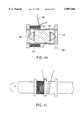
- FIG. 2is a cross-sectional view of an embodiment of a floating mass transducer.
- FIG. 3is a cross-sectional view of another embodiment of a floating mass transducer.
- FIGS. 4A and 4Bshow views of a magnet and biasing mechanisms.
- FIG. 4Cshows a cross-sectional view of a cylindrical housing with one end open.
- FIG. 4Dshows a cross-sectional view of a magnet and biasing mechanisms within the cylindrical housing.
- FIG. 4Eshows a cross-sectional view of a magnet biased within the sealed cylindrical housing.
- FIG. 4Fillustrates beginning the process of wrapping a wire around a groove in the cylindrical housing.
- FIG. 4Gillustrates the process of wrapping the wire around the groove in the cylindrical housing.
- FIG. 4Hshows a cross-sectional view of crossing the wire over to another groove in the cylindrical housing.
- FIG. 4Iillustrates the process of wrapping the wire around the other groove in the cylindrical housing.
- FIG. 4Jshows a cross-sectional view of thicker leads connected to the ends of the wire wrapped around the cylindrical housing that form a pair of coils of the floating mass transducer.
- FIG. 4Kshows a cross-section view of the thicker leads wrapped around the cylindrical housing.
- FIG. 4Lshows a clip for connecting the floating mass transducer to an ossicle within the inner ear.
- FIG. 4Mshows the clip secured to the floating mass transducer.
- FIGS. 4N and 4Oshow views of a floating mass transducer that is ready to be implanted in a patient.
- FIG. 5Ashows another clip for connecting the floating mass transducer to an ossicle within the inner ear.
- FIGS. 5B and 5Cshow views of another floating mass transducer that is ready to be implanted in a patient.
- the present inventionprovides innovative floating mass transducers for assisting hearing.
- the following descriptiondescribes preferred embodiments of the invention; however, the description is for purposes of illustration and not limitation. For example, although specific steps are described for making a floating mass transducer, the order that the steps are described should not be taken as an implication that the steps must be performed in any particular order.
- FIG. 1is a schematic representation of a portion of the auditory system showing a floating mass transducer positioned for receiving electrical signals from a subcutaneous coil inductively coupled to an external audio processor positioned outside a patient's head.
- An audio processor 100receives ambient sounds and typically processes the sounds to suit the needs of the user before transmitting signals to an implanted receiver 102.
- the audio processortypically includes a microphone, circuitry performing both signal processing and signal modulation, a battery, and a coil to transmit signals via varying magnetic fields to the receiver.
- An audio processor that may be utilized with the present inventionis described in U.S. application Ser. No. 08/526,129, filed Sept. 7, 1995, which is hereby incorporated by reference for all purposes. Additionally, an implanted audio processor may be utilized with the invention.
- Receiver 102includes a coil that transcutaneously receives signals from the audio processor in the form of varying magnetic fields in order to generate electrical signals.
- the receivertypically includes a demodulator to demodulate the electrical signals which are then transmitted to a floating mass transducer 104 via leads 106.
- the leadsreach the middle ear through a surgically created channel in the temporal bone.
- the electrical signalscause a floating mass within the housing of the floating mass transducer to vibrate.
- the floating massmay be a magnet which vibrates in response to coils connected to the housing that receive the electrical signals and generate varying magnetic fields.
- the magnetic fieldsinteract with the magnetic fields of the magnet which causes the magnet to vibrate.
- the inertial vibration of the magnetcauses the housing of the floating mass transducer to vibrate relative to the magnet.
- the housingis connected to an ossicle, the incus, by a clip so the vibration of the housing (see, e.g., double-headed arrow in FIG. 1) will vibrate the incus resulting in perception of sound by the user.
- FIG. 1illustrates one embodiment of the floating mass transducer.
- Other techniques for implantation, attachment and utilization of floating mass transducersare described in the U.S. Patents and Applications previously incorporated by reference. The following will now focus on improved floating mass transducer design.
- FIG. 2is a cross-sectional view of an embodiment of a floating mass transducer.
- a floating mass transducer 200includes a cylindrical housing 202 which is sealed by two end plates 204.
- the housingis composed of titanium and the end plates are laser welded to hermetically seal the housing.
- the cylindrical housingincludes a pair of grooves 206.
- the groovesare designed to retain wrapped wire that form coils much like bobbins retain thread.
- a wire 208is wound around one groove, crosses over to the other groove and is wound around the other groove. Accordingly, coils 210 are formed in each groove. In preferred embodiments, the coils are wound around the housing in opposite directions. Additionally, each coil may include six "layers" of wire, which is preferably insulated gold wire.
- a cylindrical magnet 212Within the housing is a cylindrical magnet 212.
- the diameter of the magnetis less than the inner diameter of the housing which allows the magnet to move or "float" within the housing.
- the magnetis biased within the housing by a pair of silicone springs 212 so that the poles of the magnet are generally surrounded by coils 210.
- the silicone springsact like springs which allow the magnet to vibrate relative to the housing resulting in inertial vibration of the housing. As shown, each silicone spring is retained within an indentation in an end plate.
- the silicone springsmay be glued or otherwise secured within the indentations.
- the silicone springsrely on surface friction to retain the magnet centered within the housing so that there is minimal friction with the interior surface of the housing. It has been discovered that it would be preferable to have the silicone springs positively retain the magnet centered within the housing not in contact with the interior surface of the housing.
- One way to achieve thisis to create indentation in the ends of the magnet such that the ends of the silicone springs nearest the magnet will reside in the indentations in the magnet. It may preferable, however, to accomplish the same result without creating indentations in the magnet.
- FIG. 3is a cross-sectional view of another embodiment of a floating mass transducer.
- the reference numerals utilized in FIG. 3refer to corresponding structures in FIG. 2.
- the silicone springshave been reversed as follows.
- Silicone springs 214are secured to magnet 212 by, e.g., an adhesive. End plates 204 have indentations within which an end of the silicone springs are retained. In this manner, the magnet biased within the center of the housing but not in contact with the interior surface of the housing.
- FIGS. 4A-4Mwill illustrate a process of making the floating mass transducer shown in FIG. 3.
- FIGS. 4A and 4Bshow views of a magnet and biasing mechanisms.
- the left side of the figureshows a cross-sectional view including magnet 212 and silicone springs 214.
- the silicone springsare secured to the magnet by an adhesive 302.
- the right side of the figureshows the magnet and biasing mechanisms along the line indicated by A.
- FIG. 4Cshows a cross-sectional view of a cylindrical housing with one end open.
- Cylindrical housing 202is shown with one end plate 204 secured to seal up one end of the housing.
- the end platesare laser welded.
- FIG. 4Cshows a cross-sectional view of a magnet and biasing mechanisms within the cylindrical housing.
- the magnet and biasing mechanismsare placed within the cylindrical housing through the open end.
- FIG. 4Eshows a cross-sectional view of a magnet biased within the sealed cylindrical housing. End plate 204 is secured to the open end of the housing and is preferably laser welded to seal the housing.
- FIG. 4Fillustrates beginning the process of wrapping a wire around a groove in the cylindrical housing.
- the wireincludes a low resistance, biocompatible material.
- the housingis placed in a lathe 322 (although not a traditional lathe, the apparatus will be called that since both rotate objects).
- wire 208is wrapped around the housing within one of grooves 206 starting at a flange 353 between the two grooves.
- a medical grade adhesivelike Loctite glue may be placed within the groove to help hold the wire in place within the groove.
- the latheis turned in a counter-clockwise direction. Although the actual direction of rotation is not critical, it is being specified here to more clearly demonstrate the process of making the floating mass transducer.
- FIG. 4Gillustrates the process of wrapping the wire around the groove in the cylindrical housing.
- wire 208is wrapped around the housing in the groove in the direction of the arrow (the windings have been spaced out to more clearly illustrate this point).
- the wireOnce the wire reaches an end of the groove, the wire continues to be wound in the groove but toward the other end of the groove. As mentioned earlier, this is similar to how thread is wound onto a bobbin or spool.
- the wireis wound six layers deep which would place the wire at the center of the housing.
- FIG. 4Hshows a cross-sectional view of crossing the wire over to another groove in the cylindrical housing.
- FIG. 4Iillustrates the process of wrapping the wire around the other groove in the cylindrical housing.
- the wireis wound around the other groove in a manner similar to the manner that was described in reference to FIGS. 4F and 4F except that the lathe now rotates the housing in the opposite direction, or clock-wise as indicated. Again the windings are shown spaced out for clarity.
- both ends of the wireare near the center of the housing.
- Thicker leads 372may then welded to the thinner wire as shown in the cross-section view of FIG. 4I.
- FIG. 4Kshows a cross-section view of the thicker leads wrapped around the cylindrical housing.
- the thicker leadsare shown wrapped around the housing one time which may alleviate stress on the weld between the leads and the wire.
- FIG. 4Lshows a clip for connecting the floating mass transducer to an ossicle within the inner ear.
- a clip 402has an end 404 for attachment to the housing of the floating mass transducer and an end 406 that is curved in the form of a "C" so that it may be easily clamped on an ossicle like the incus.
- the cliphas two pairs of opposing prongs that, when bent, allow for attachment to an ossicle. Although two pairs of prongs are shown, more may be utilized.
- FIG. 4Mshows the clip secured to the floating mass transducer.
- End 404is wrapped and welded around one end of housing 202 of the floating mass transducer as shown.
- End 406 of the clipis then available for being clamped on an ossicle. As shown, the clip may be clamped onto the incus near where the incus contacts the stapes.
- FIG. 4Nshows views of a floating mass transducer that is ready to be implanted in a patient.
- the left side of the figureshows a cross-sectional view of the floating mass transducer.
- the housingincludes a coating 502 which is made of a biocompatible material such as acrylic epoxy, biocompatible hard epoxy, and the like.
- Leads 372are threaded through a sheath 504 which is secured to the housing with an adhesive 506.
- the right side of the figureshows the floating mass transducer along the line indicated by A.
- FIG. 5Ashows another clip for connecting the floating mass transducer to an ossicle within the inner ear.
- a clip 602has an end 604 that for attachment to the housing of the floating mass transducer and an end 606 that is curved in the form of a "C" so that it may be easily clamped on an ossicle like the incus.
- the cliphas rectangular prongs with openings therethrough.
- FIG. 5Bshows views of another floating mass transducer that is ready to be implanted in a patient.
- the left side of the figureshows a cross-sectional view of the floating mass transducer.
- the housingincludes coating 502 and leads 372 are threaded through sheath 504 which is secured to the housing with adhesive 506.
- Clip 602is not shown as the cross-section does not intercept the clip. However, the position of the clip is seen on the right side of the figure which shows the floating mass transducer along the line indicated by A.
- Clip 602extends away from the floating mass transducer perpendicular to leads 372. Additionally, the clip is twisted 90° to improve the ability to clip the floating mass transducer to an ossicle.
Landscapes
- General Health & Medical Sciences (AREA)
- Otolaryngology (AREA)
- Health & Medical Sciences (AREA)
- Neurosurgery (AREA)
- Physics & Mathematics (AREA)
- Engineering & Computer Science (AREA)
- Acoustics & Sound (AREA)
- Signal Processing (AREA)
- Electrostatic, Electromagnetic, Magneto- Strictive, And Variable-Resistance Transducers (AREA)
- Measuring Fluid Pressure (AREA)
- Investigating Or Analyzing Materials By The Use Of Ultrasonic Waves (AREA)
- Apparatus For Radiation Diagnosis (AREA)
- Ultra Sonic Daignosis Equipment (AREA)
- Measuring Pulse, Heart Rate, Blood Pressure Or Blood Flow (AREA)
- Measurement Of Velocity Or Position Using Acoustic Or Ultrasonic Waves (AREA)
- Apparatuses For Generation Of Mechanical Vibrations (AREA)
Abstract
Description
Claims (27)
Priority Applications (8)
| Application Number | Priority Date | Filing Date | Title |
|---|---|---|---|
| US08/816,115US5897486A (en) | 1993-07-01 | 1997-03-11 | Dual coil floating mass transducers |
| DE69840293TDE69840293D1 (en) | 1997-03-11 | 1998-03-09 | IMPROVED CONVERTER WITH SWIVEL MASS PULSE PAIR |
| AU64550/98AAU6455098A (en) | 1997-03-11 | 1998-03-09 | Improved dual coil floating mass transducers |
| EP98910266AEP0974244B1 (en) | 1997-03-11 | 1998-03-09 | Improved dual coil floating mass transducers |
| PCT/US1998/004593WO1998041056A1 (en) | 1997-03-11 | 1998-03-09 | Improved dual coil floating mass transducers |
| ES98910266TES2318870T3 (en) | 1997-03-11 | 1998-03-09 | IMPROVED DOUBLE COIL MASS TRANSDUCERS. |
| AT98910266TATE416590T1 (en) | 1997-03-11 | 1998-03-09 | IMPROVED TRANSDUCER WITH VIBRATION MASS COIL PAIR |
| US09/231,851US6475134B1 (en) | 1993-07-01 | 1999-01-14 | Dual coil floating mass transducers |
Applications Claiming Priority (6)
| Application Number | Priority Date | Filing Date | Title |
|---|---|---|---|
| US08/087,618US5456654A (en) | 1993-07-01 | 1993-07-01 | Implantable magnetic hearing aid transducer |
| US08/225,153US5554096A (en) | 1993-07-01 | 1994-04-08 | Implantable electromagnetic hearing transducer |
| US08/368,219US5624376A (en) | 1993-07-01 | 1995-01-03 | Implantable and external hearing systems having a floating mass transducer |
| US08/568,006US5913815A (en) | 1993-07-01 | 1995-12-06 | Bone conducting floating mass transducers |
| US08/582,301US5800336A (en) | 1993-07-01 | 1996-01-03 | Advanced designs of floating mass transducers |
| US08/816,115US5897486A (en) | 1993-07-01 | 1997-03-11 | Dual coil floating mass transducers |
Related Parent Applications (1)
| Application Number | Title | Priority Date | Filing Date |
|---|---|---|---|
| US08/582,301Continuation-In-PartUS5800336A (en) | 1993-07-01 | 1996-01-03 | Advanced designs of floating mass transducers |
Related Child Applications (1)
| Application Number | Title | Priority Date | Filing Date |
|---|---|---|---|
| US09/231,851ContinuationUS6475134B1 (en) | 1993-07-01 | 1999-01-14 | Dual coil floating mass transducers |
Publications (1)
| Publication Number | Publication Date |
|---|---|
| US5897486Atrue US5897486A (en) | 1999-04-27 |
Family
ID=25219731
Family Applications (2)
| Application Number | Title | Priority Date | Filing Date |
|---|---|---|---|
| US08/816,115Expired - LifetimeUS5897486A (en) | 1993-07-01 | 1997-03-11 | Dual coil floating mass transducers |
| US09/231,851Expired - LifetimeUS6475134B1 (en) | 1993-07-01 | 1999-01-14 | Dual coil floating mass transducers |
Family Applications After (1)
| Application Number | Title | Priority Date | Filing Date |
|---|---|---|---|
| US09/231,851Expired - LifetimeUS6475134B1 (en) | 1993-07-01 | 1999-01-14 | Dual coil floating mass transducers |
Country Status (7)
| Country | Link |
|---|---|
| US (2) | US5897486A (en) |
| EP (1) | EP0974244B1 (en) |
| AT (1) | ATE416590T1 (en) |
| AU (1) | AU6455098A (en) |
| DE (1) | DE69840293D1 (en) |
| ES (1) | ES2318870T3 (en) |
| WO (1) | WO1998041056A1 (en) |
Cited By (86)
| Publication number | Priority date | Publication date | Assignee | Title |
|---|---|---|---|---|
| US6193645B1 (en)* | 1997-08-07 | 2001-02-27 | St. Croix Medical, Inc. | Electromagnetic input transducers for middle ear sensing |
| WO2001093634A1 (en)* | 2000-06-02 | 2001-12-06 | P & B Research Ab | Vibrator for bone conducted hearing aids |
| US6381336B1 (en)* | 1996-05-24 | 2002-04-30 | S. George Lesinski | Microphones for an implatable hearing aid |
| US6505076B2 (en)* | 2000-12-08 | 2003-01-07 | Advanced Bionics Corporation | Water-resistant, wideband microphone subassembly |
| US6537201B1 (en) | 2001-09-28 | 2003-03-25 | Otologics Llc | Implantable hearing aid with improved sealing |
| US6629922B1 (en) | 1999-10-29 | 2003-10-07 | Soundport Corporation | Flextensional output actuators for surgically implantable hearing aids |
| US20030220536A1 (en)* | 2002-05-21 | 2003-11-27 | Hissong James B. | Apparatus and methods for directly displacing the partition between the middle ear and inner ear at an infrasonic frequency |
| WO2003101317A1 (en)* | 1999-06-11 | 2003-12-11 | Ewing David L | Magnetic therapeutic device |
| US6676592B2 (en)* | 1993-07-01 | 2004-01-13 | Symphonix Devices, Inc. | Dual coil floating mass transducers |
| US6689045B2 (en) | 1998-09-24 | 2004-02-10 | St. Croix Medical, Inc. | Method and apparatus for improving signal quality in implantable hearing systems |
| US20040032962A1 (en)* | 2000-06-02 | 2004-02-19 | Patrik Westerkull | Bone conducting hearing aid |
| US6707920B2 (en) | 2000-12-12 | 2004-03-16 | Otologics Llc | Implantable hearing aid microphone |
| US20040151938A1 (en)* | 2001-05-25 | 2004-08-05 | Gorm Danscher | Method of implanting heavy metal such as nobel metal, e.g.gold, and metal for use in implantation |
| WO2004114723A2 (en) | 2003-06-26 | 2004-12-29 | Med-El Elektromedizinische Geraete Gmbh | Electromagnetic transducer with reduced sensitivity to external magnetic fields, and method of improving hearing or sensing vibrations using such a transducer |
| US20050101831A1 (en)* | 2003-11-07 | 2005-05-12 | Miller Scott A.Iii | Active vibration attenuation for implantable microphone |
| US20050101832A1 (en)* | 2003-11-07 | 2005-05-12 | Miller Scott A.Iii | Microphone optimized for implant use |
| US20050203557A1 (en)* | 2001-10-30 | 2005-09-15 | Lesinski S. G. | Implantation method for a hearing aid microactuator implanted into the cochlea |
| US20050222487A1 (en)* | 2004-04-01 | 2005-10-06 | Miller Scott A Iii | Low acceleration sensitivity microphone |
| US20060189841A1 (en)* | 2004-10-12 | 2006-08-24 | Vincent Pluvinage | Systems and methods for photo-mechanical hearing transduction |
| WO2006091808A3 (en)* | 2005-02-25 | 2006-09-28 | Medical Res Products B Inc | Fully implantable hearing aid system |
| US20060251278A1 (en)* | 2005-05-03 | 2006-11-09 | Rodney Perkins And Associates | Hearing system having improved high frequency response |
| US20070009132A1 (en)* | 2005-07-08 | 2007-01-11 | Miller Scott A Iii | Implantable microphone with shaped chamber |
| US20070083078A1 (en)* | 2005-10-06 | 2007-04-12 | Easter James R | Implantable transducer with transverse force application |
| US20070113964A1 (en)* | 2001-12-10 | 2007-05-24 | Crawford Scott A | Small water-repellant microphone having improved acoustic performance and method of constructing same |
| US20070126540A1 (en)* | 2002-04-01 | 2007-06-07 | Med-El Elektromedizinische Geraete Gmbh | System and Method for Reducing Effect of Magnetic Fields on a Magnetic Transducer |
| US20070167671A1 (en)* | 2005-11-30 | 2007-07-19 | Miller Scott A Iii | Dual feedback control system for implantable hearing instrument |
| US20070282397A1 (en)* | 2002-09-10 | 2007-12-06 | Vibrant Med-El Hearing Technology Gmbh | Implantable medical devices with multiple transducers |
| US7319771B2 (en) | 2000-06-02 | 2008-01-15 | P & B Research Ab | Vibrator for bone conducted hearing aids |
| US20080132750A1 (en)* | 2005-01-11 | 2008-06-05 | Scott Allan Miller | Adaptive cancellation system for implantable hearing instruments |
| US20080255406A1 (en)* | 2007-03-29 | 2008-10-16 | Vibrant Med-El Hearing Technology Gmbh | Implantable Auditory Stimulation Systems Having a Transducer and a Transduction Medium |
| US20090092271A1 (en)* | 2007-10-04 | 2009-04-09 | Earlens Corporation | Energy Delivery and Microphone Placement Methods for Improved Comfort in an Open Canal Hearing Aid |
| US20090097681A1 (en)* | 2007-10-12 | 2009-04-16 | Earlens Corporation | Multifunction System and Method for Integrated Hearing and Communication with Noise Cancellation and Feedback Management |
| US20090112051A1 (en)* | 2007-10-30 | 2009-04-30 | Miller Iii Scott Allan | Observer-based cancellation system for implantable hearing instruments |
| US20090134721A1 (en)* | 2002-04-01 | 2009-05-28 | Med-El Elektromedisinische Geraete Gmbh | MRI-safe Electro-magnetic Tranducer |
| EP2094029A2 (en) | 2008-02-20 | 2009-08-26 | Osseofon AB | Implantable transducer |
| US20090287277A1 (en)* | 2008-05-19 | 2009-11-19 | Otologics, Llc | Implantable neurostimulation electrode interface |
| US20100004716A1 (en)* | 2002-04-01 | 2010-01-07 | Med-El Elektromedizinische Geraete Gmbh | Reducing Effect of Magnetic and Electromagnetic Fields on an Implant's Magnet and/or Electronics |
| US20100048982A1 (en)* | 2008-06-17 | 2010-02-25 | Earlens Corporation | Optical Electro-Mechanical Hearing Devices With Separate Power and Signal Components |
| US20100069997A1 (en)* | 2008-09-16 | 2010-03-18 | Otologics, Llc | Neurostimulation apparatus |
| US7775964B2 (en) | 2005-01-11 | 2010-08-17 | Otologics Llc | Active vibration attenuation for implantable microphone |
| US7840020B1 (en) | 2004-04-01 | 2010-11-23 | Otologics, Llc | Low acceleration sensitivity microphone |
| WO2010141895A1 (en) | 2009-06-05 | 2010-12-09 | SoundBeam LLC | Optically coupled acoustic middle ear implant systems and methods |
| US20100317914A1 (en)* | 2009-06-15 | 2010-12-16 | SoundBeam LLC | Optically Coupled Active Ossicular Replacement Prosthesis |
| WO2011005500A2 (en) | 2009-06-22 | 2011-01-13 | SoundBeam LLC | Round window coupled hearing systems and methods |
| US20110022120A1 (en)* | 2009-07-22 | 2011-01-27 | Vibrant Med-El Hearing Technology Gmbh | Magnetic Attachment Arrangement for Implantable Device |
| US20110082327A1 (en)* | 2009-10-07 | 2011-04-07 | Manning Miles Goldsmith | Saline membranous coupling mechanism for electromagnetic and piezoelectric round window direct drive systems for hearing amplification |
| US20110144719A1 (en)* | 2009-06-18 | 2011-06-16 | SoundBeam LLC | Optically Coupled Cochlear Implant Systems and Methods |
| US20110142274A1 (en)* | 2009-06-18 | 2011-06-16 | SoundBeam LLC | Eardrum Implantable Devices For Hearing Systems and Methods |
| WO2012116130A1 (en)* | 2011-02-24 | 2012-08-30 | Vibrant Med-El Hearing Technology Gmbh | Mri safe actuator for implantable floating mass transducer |
| US8385580B2 (en) | 2006-08-31 | 2013-02-26 | Adamson Systems Engineering Inc. | High power low frequency transducers and method of assembly |
| US8396239B2 (en) | 2008-06-17 | 2013-03-12 | Earlens Corporation | Optical electro-mechanical hearing devices with combined power and signal architectures |
| US8715154B2 (en) | 2009-06-24 | 2014-05-06 | Earlens Corporation | Optically coupled cochlear actuator systems and methods |
| US8715153B2 (en) | 2009-06-22 | 2014-05-06 | Earlens Corporation | Optically coupled bone conduction systems and methods |
| US8774930B2 (en) | 2009-07-22 | 2014-07-08 | Vibrant Med-El Hearing Technology Gmbh | Electromagnetic bone conduction hearing device |
| US8824715B2 (en) | 2008-06-17 | 2014-09-02 | Earlens Corporation | Optical electro-mechanical hearing devices with combined power and signal architectures |
| US8845705B2 (en) | 2009-06-24 | 2014-09-30 | Earlens Corporation | Optical cochlear stimulation devices and methods |
| US8858419B2 (en) | 2008-09-22 | 2014-10-14 | Earlens Corporation | Balanced armature devices and methods for hearing |
| US8897475B2 (en) | 2011-12-22 | 2014-11-25 | Vibrant Med-El Hearing Technology Gmbh | Magnet arrangement for bone conduction hearing implant |
| US9044588B2 (en) | 2009-04-16 | 2015-06-02 | Cochlear Limited | Reference electrode apparatus and method for neurostimulation implants |
| US9295425B2 (en) | 2002-04-01 | 2016-03-29 | Med-El Elektromedizinische Geraete Gmbh | Transducer for stapedius monitoring |
| US9392377B2 (en) | 2010-12-20 | 2016-07-12 | Earlens Corporation | Anatomically customized ear canal hearing apparatus |
| US9420388B2 (en) | 2012-07-09 | 2016-08-16 | Med-El Elektromedizinische Geraete Gmbh | Electromagnetic bone conduction hearing device |
| US20160345107A1 (en) | 2015-05-21 | 2016-11-24 | Cochlear Limited | Advanced management of an implantable sound management system |
| US9924276B2 (en) | 2014-11-26 | 2018-03-20 | Earlens Corporation | Adjustable venting for hearing instruments |
| US9930458B2 (en) | 2014-07-14 | 2018-03-27 | Earlens Corporation | Sliding bias and peak limiting for optical hearing devices |
| US10034103B2 (en) | 2014-03-18 | 2018-07-24 | Earlens Corporation | High fidelity and reduced feedback contact hearing apparatus and methods |
| US10058702B2 (en) | 2003-04-09 | 2018-08-28 | Cochlear Limited | Implant magnet system |
| US10130807B2 (en) | 2015-06-12 | 2018-11-20 | Cochlear Limited | Magnet management MRI compatibility |
| US10178483B2 (en) | 2015-12-30 | 2019-01-08 | Earlens Corporation | Light based hearing systems, apparatus, and methods |
| US10292601B2 (en) | 2015-10-02 | 2019-05-21 | Earlens Corporation | Wearable customized ear canal apparatus |
| US10341789B2 (en) | 2014-10-20 | 2019-07-02 | Cochlear Limited | Implantable auditory prosthesis with floating mass transducer |
| US10492010B2 (en) | 2015-12-30 | 2019-11-26 | Earlens Corporations | Damping in contact hearing systems |
| US10516953B2 (en) | 2009-05-29 | 2019-12-24 | Cochlear Limited | Implantable auditory stimulation system and method with offset implanted microphones |
| US10576276B2 (en) | 2016-04-29 | 2020-03-03 | Cochlear Limited | Implanted magnet management in the face of external magnetic fields |
| US10848882B2 (en) | 2007-05-24 | 2020-11-24 | Cochlear Limited | Implant abutment |
| US10917730B2 (en) | 2015-09-14 | 2021-02-09 | Cochlear Limited | Retention magnet system for medical device |
| US11071869B2 (en) | 2016-02-24 | 2021-07-27 | Cochlear Limited | Implantable device having removable portion |
| US11102594B2 (en) | 2016-09-09 | 2021-08-24 | Earlens Corporation | Contact hearing systems, apparatus and methods |
| US11166114B2 (en) | 2016-11-15 | 2021-11-02 | Earlens Corporation | Impression procedure |
| US11212626B2 (en) | 2018-04-09 | 2021-12-28 | Earlens Corporation | Dynamic filter |
| US11350226B2 (en) | 2015-12-30 | 2022-05-31 | Earlens Corporation | Charging protocol for rechargeable hearing systems |
| US11516603B2 (en) | 2018-03-07 | 2022-11-29 | Earlens Corporation | Contact hearing device and retention structure materials |
| US11595768B2 (en) | 2016-12-02 | 2023-02-28 | Cochlear Limited | Retention force increasing components |
| US11792587B1 (en) | 2015-06-26 | 2023-10-17 | Cochlear Limited | Magnetic retention device |
| US12003925B2 (en) | 2014-07-29 | 2024-06-04 | Cochlear Limited | Magnetic retention system |
| US12420101B2 (en) | 2019-09-27 | 2025-09-23 | Cochlear Limited | Multipole magnet for medical implant system |
Families Citing this family (9)
| Publication number | Priority date | Publication date | Assignee | Title |
|---|---|---|---|---|
| US7471801B2 (en)* | 2002-05-10 | 2008-12-30 | Osseofon Ab | Device for the generation of or monitoring of vibrations |
| US7570261B1 (en)* | 2003-03-06 | 2009-08-04 | Xdyne, Inc. | Apparatus and method for creating a virtual three-dimensional environment, and method of generating revenue therefrom |
| US7651460B2 (en)* | 2004-03-22 | 2010-01-26 | The Board Of Regents Of The University Of Oklahoma | Totally implantable hearing system |
| US7955249B2 (en)* | 2005-10-31 | 2011-06-07 | Earlens Corporation | Output transducers for hearing systems |
| US7421087B2 (en)* | 2004-07-28 | 2008-09-02 | Earlens Corporation | Transducer for electromagnetic hearing devices |
| US8246532B2 (en)* | 2006-02-14 | 2012-08-21 | Vibrant Med-El Hearing Technology Gmbh | Bone conductive devices for improving hearing |
| US8737649B2 (en)* | 2008-03-31 | 2014-05-27 | Cochlear Limited | Bone conduction device with a user interface |
| WO2009155650A1 (en) | 2008-06-25 | 2009-12-30 | Cochlear Limited | Enhanced performance implantable microphone system |
| KR100999690B1 (en)* | 2008-07-08 | 2010-12-08 | 단국대학교 산학협력단 | Tympanic vibration device for implantable hearing aid and installation device for tympanic vibration device |
Citations (48)
| Publication number | Priority date | Publication date | Assignee | Title |
|---|---|---|---|---|
| US3594514A (en)* | 1970-01-02 | 1971-07-20 | Medtronic Inc | Hearing aid with piezoelectric ceramic element |
| US3712962A (en)* | 1971-04-05 | 1973-01-23 | J Epley | Implantable piezoelectric hearing aid |
| US3752939A (en)* | 1972-02-04 | 1973-08-14 | Beckman Instruments Inc | Prosthetic device for the deaf |
| US3764748A (en)* | 1972-05-19 | 1973-10-09 | J Branch | Implanted hearing aids |
| US3870832A (en)* | 1972-07-18 | 1975-03-11 | John M Fredrickson | Implantable electromagnetic hearing aid |
| US3882285A (en)* | 1973-10-09 | 1975-05-06 | Vicon Instr Company | Implantable hearing aid and method of improving hearing |
| US4063049A (en)* | 1975-12-30 | 1977-12-13 | Societa Italiana Telecomunicazioni Siemens S.P.A. | Piezoelectric electroacoustic transducer |
| US4063048A (en)* | 1977-03-16 | 1977-12-13 | Kissiah Jr Adam M | Implantable electronic hearing aid |
| US4352960A (en)* | 1980-09-30 | 1982-10-05 | Baptist Medical Center Of Oklahoma, Inc. | Magnetic transcutaneous mount for external device of an associated implant |
| US4357497A (en)* | 1979-09-24 | 1982-11-02 | Hochmair Ingeborg | System for enhancing auditory stimulation and the like |
| US4606329A (en)* | 1985-05-22 | 1986-08-19 | Xomed, Inc. | Implantable electromagnetic middle-ear bone-conduction hearing aid device |
| US4611598A (en)* | 1984-05-30 | 1986-09-16 | Hortmann Gmbh | Multi-frequency transmission system for implanted hearing aids |
| US4612915A (en)* | 1985-05-23 | 1986-09-23 | Xomed, Inc. | Direct bone conduction hearing aid device |
| US4628907A (en)* | 1984-03-22 | 1986-12-16 | Epley John M | Direct contact hearing aid apparatus |
| US4696287A (en)* | 1985-02-26 | 1987-09-29 | Hortmann Gmbh | Transmission system for implanted hearing aids |
| US4728327A (en)* | 1986-01-27 | 1988-03-01 | Michel Gersdorff | Middle-ear prosthesis |
| US4729366A (en)* | 1984-12-04 | 1988-03-08 | Medical Devices Group, Inc. | Implantable hearing aid and method of improving hearing |
| US4756312A (en)* | 1984-03-22 | 1988-07-12 | Advanced Hearing Technology, Inc. | Magnetic attachment device for insertion and removal of hearing aid |
| US4776322A (en)* | 1985-05-22 | 1988-10-11 | Xomed, Inc. | Implantable electromagnetic middle-ear bone-conduction hearing aid device |
| US4800884A (en)* | 1986-03-07 | 1989-01-31 | Richards Medical Company | Magnetic induction hearing aid |
| US4817607A (en)* | 1986-03-07 | 1989-04-04 | Richards Medical Company | Magnetic ossicular replacement prosthesis |
| US4817609A (en)* | 1987-09-11 | 1989-04-04 | Resound Corporation | Method for treating hearing deficiencies |
| US4832051A (en)* | 1985-04-29 | 1989-05-23 | Symbion, Inc. | Multiple-electrode intracochlear device |
| US4840178A (en)* | 1986-03-07 | 1989-06-20 | Richards Metal Company | Magnet for installation in the middle ear |
| US4918745A (en)* | 1987-10-09 | 1990-04-17 | Storz Instrument Company | Multi-channel cochlear implant system |
| US4936305A (en)* | 1988-07-20 | 1990-06-26 | Richards Medical Company | Shielded magnetic assembly for use with a hearing aid |
| US4957478A (en)* | 1988-10-17 | 1990-09-18 | Maniglia Anthony J | Partially implantable hearing aid device |
| US4969900A (en)* | 1987-03-06 | 1990-11-13 | Gerald Fleischer | Middle ear prosthesis and method for mounting it |
| US4988333A (en)* | 1988-09-09 | 1991-01-29 | Storz Instrument Company | Implantable middle ear hearing aid system and acoustic coupler therefor |
| US5015224A (en)* | 1988-10-17 | 1991-05-14 | Maniglia Anthony J | Partially implantable hearing aid device |
| US5015225A (en)* | 1985-05-22 | 1991-05-14 | Xomed, Inc. | Implantable electromagnetic middle-ear bone-conduction hearing aid device |
| US5047994A (en)* | 1989-05-30 | 1991-09-10 | Center For Innovative Technology | Supersonic bone conduction hearing aid and method |
| US5085628A (en)* | 1988-09-09 | 1992-02-04 | Storz Instrument Company | Implantable hearing aid coupler device |
| US5163957A (en)* | 1991-09-10 | 1992-11-17 | Smith & Nephew Richards, Inc. | Ossicular prosthesis for mounting magnet |
| US5220918A (en)* | 1988-11-16 | 1993-06-22 | Smith & Nephew Richards, Inc. | Trans-tympanic connector for magnetic induction hearing aid |
| US5259033A (en)* | 1989-08-30 | 1993-11-02 | Gn Danavox As | Hearing aid having compensation for acoustic feedback |
| US5257623A (en)* | 1989-03-06 | 1993-11-02 | Karasev Alexandr A | Apparatus for generating electric pulses for biological object stimulation |
| US5259032A (en)* | 1990-11-07 | 1993-11-02 | Resound Corporation | contact transducer assembly for hearing devices |
| US5277694A (en)* | 1991-02-13 | 1994-01-11 | Implex Gmbh | Electromechanical transducer for implantable hearing aids |
| US5282858A (en)* | 1991-06-17 | 1994-02-01 | American Cyanamid Company | Hermetically sealed implantable transducer |
| US5295193A (en)* | 1992-01-22 | 1994-03-15 | Hiroshi Ono | Device for picking up bone-conducted sound in external auditory meatus and communication device using the same |
| US5338287A (en)* | 1991-12-23 | 1994-08-16 | Miller Gale W | Electromagnetic induction hearing aid device |
| US5356430A (en)* | 1991-06-10 | 1994-10-18 | Nadol Jr Joseph B | Hearing prosthesis |
| US5447489A (en)* | 1989-08-17 | 1995-09-05 | Issalene; Robert | Bone conduction hearing aid device |
| US5456654A (en)* | 1993-07-01 | 1995-10-10 | Ball; Geoffrey R. | Implantable magnetic hearing aid transducer |
| US5531787A (en)* | 1993-01-25 | 1996-07-02 | Lesinski; S. George | Implantable auditory system with micromachined microsensor and microactuator |
| US5554096A (en)* | 1993-07-01 | 1996-09-10 | Symphonix | Implantable electromagnetic hearing transducer |
| US5624376A (en)* | 1993-07-01 | 1997-04-29 | Symphonix Devices, Inc. | Implantable and external hearing systems having a floating mass transducer |
Family Cites Families (7)
| Publication number | Priority date | Publication date | Assignee | Title |
|---|---|---|---|---|
| DE3918329A1 (en)* | 1989-06-05 | 1990-12-06 | Hortmann Gmbh | Hearing aid with electrical stimulation of inner ear - has microphone coupled to implanted system with inductive coupling element |
| US5949835A (en) | 1991-07-01 | 1999-09-07 | The United States Of America As Represented By The Secretary Of The Navy | Steady-state, high dose neutron generation and concentration apparatus and method for deuterium atoms |
| US5800336A (en) | 1993-07-01 | 1998-09-01 | Symphonix Devices, Inc. | Advanced designs of floating mass transducers |
| US5913815A (en)* | 1993-07-01 | 1999-06-22 | Symphonix Devices, Inc. | Bone conducting floating mass transducers |
| WO1996017563A1 (en)* | 1994-12-09 | 1996-06-13 | Cochlear Pty. Limited | A clip for cochlea electrode lead fixation and method of using the same |
| US5949895A (en) | 1995-09-07 | 1999-09-07 | Symphonix Devices, Inc. | Disposable audio processor for use with implanted hearing devices |
| US5943815A (en) | 1997-03-14 | 1999-08-31 | University Of Florida | Method and delivery system for the carbon dioxide-based, area specific attraction of insects |
- 1997
- 1997-03-11USUS08/816,115patent/US5897486A/ennot_activeExpired - Lifetime
- 1998
- 1998-03-09ATAT98910266Tpatent/ATE416590T1/enactive
- 1998-03-09ESES98910266Tpatent/ES2318870T3/ennot_activeExpired - Lifetime
- 1998-03-09AUAU64550/98Apatent/AU6455098A/ennot_activeAbandoned
- 1998-03-09WOPCT/US1998/004593patent/WO1998041056A1/enactiveApplication Filing
- 1998-03-09DEDE69840293Tpatent/DE69840293D1/ennot_activeExpired - Lifetime
- 1998-03-09EPEP98910266Apatent/EP0974244B1/ennot_activeExpired - Lifetime
- 1999
- 1999-01-14USUS09/231,851patent/US6475134B1/ennot_activeExpired - Lifetime
Patent Citations (49)
| Publication number | Priority date | Publication date | Assignee | Title |
|---|---|---|---|---|
| US3594514A (en)* | 1970-01-02 | 1971-07-20 | Medtronic Inc | Hearing aid with piezoelectric ceramic element |
| US3712962A (en)* | 1971-04-05 | 1973-01-23 | J Epley | Implantable piezoelectric hearing aid |
| US3752939A (en)* | 1972-02-04 | 1973-08-14 | Beckman Instruments Inc | Prosthetic device for the deaf |
| US3764748A (en)* | 1972-05-19 | 1973-10-09 | J Branch | Implanted hearing aids |
| US3870832A (en)* | 1972-07-18 | 1975-03-11 | John M Fredrickson | Implantable electromagnetic hearing aid |
| GB1440724A (en)* | 1972-07-18 | 1976-06-23 | Fredrickson J M | Implantable electromagnetic hearing aid |
| US3882285A (en)* | 1973-10-09 | 1975-05-06 | Vicon Instr Company | Implantable hearing aid and method of improving hearing |
| US4063049A (en)* | 1975-12-30 | 1977-12-13 | Societa Italiana Telecomunicazioni Siemens S.P.A. | Piezoelectric electroacoustic transducer |
| US4063048A (en)* | 1977-03-16 | 1977-12-13 | Kissiah Jr Adam M | Implantable electronic hearing aid |
| US4357497A (en)* | 1979-09-24 | 1982-11-02 | Hochmair Ingeborg | System for enhancing auditory stimulation and the like |
| US4352960A (en)* | 1980-09-30 | 1982-10-05 | Baptist Medical Center Of Oklahoma, Inc. | Magnetic transcutaneous mount for external device of an associated implant |
| US4628907A (en)* | 1984-03-22 | 1986-12-16 | Epley John M | Direct contact hearing aid apparatus |
| US4756312A (en)* | 1984-03-22 | 1988-07-12 | Advanced Hearing Technology, Inc. | Magnetic attachment device for insertion and removal of hearing aid |
| US4611598A (en)* | 1984-05-30 | 1986-09-16 | Hortmann Gmbh | Multi-frequency transmission system for implanted hearing aids |
| US4729366A (en)* | 1984-12-04 | 1988-03-08 | Medical Devices Group, Inc. | Implantable hearing aid and method of improving hearing |
| US4696287A (en)* | 1985-02-26 | 1987-09-29 | Hortmann Gmbh | Transmission system for implanted hearing aids |
| US4832051A (en)* | 1985-04-29 | 1989-05-23 | Symbion, Inc. | Multiple-electrode intracochlear device |
| US4606329A (en)* | 1985-05-22 | 1986-08-19 | Xomed, Inc. | Implantable electromagnetic middle-ear bone-conduction hearing aid device |
| US4776322A (en)* | 1985-05-22 | 1988-10-11 | Xomed, Inc. | Implantable electromagnetic middle-ear bone-conduction hearing aid device |
| US5015225A (en)* | 1985-05-22 | 1991-05-14 | Xomed, Inc. | Implantable electromagnetic middle-ear bone-conduction hearing aid device |
| US4612915A (en)* | 1985-05-23 | 1986-09-23 | Xomed, Inc. | Direct bone conduction hearing aid device |
| US4728327A (en)* | 1986-01-27 | 1988-03-01 | Michel Gersdorff | Middle-ear prosthesis |
| US4840178A (en)* | 1986-03-07 | 1989-06-20 | Richards Metal Company | Magnet for installation in the middle ear |
| US4817607A (en)* | 1986-03-07 | 1989-04-04 | Richards Medical Company | Magnetic ossicular replacement prosthesis |
| US4800884A (en)* | 1986-03-07 | 1989-01-31 | Richards Medical Company | Magnetic induction hearing aid |
| US4969900A (en)* | 1987-03-06 | 1990-11-13 | Gerald Fleischer | Middle ear prosthesis and method for mounting it |
| US4817609A (en)* | 1987-09-11 | 1989-04-04 | Resound Corporation | Method for treating hearing deficiencies |
| US4918745A (en)* | 1987-10-09 | 1990-04-17 | Storz Instrument Company | Multi-channel cochlear implant system |
| US4936305A (en)* | 1988-07-20 | 1990-06-26 | Richards Medical Company | Shielded magnetic assembly for use with a hearing aid |
| US5085628A (en)* | 1988-09-09 | 1992-02-04 | Storz Instrument Company | Implantable hearing aid coupler device |
| US4988333A (en)* | 1988-09-09 | 1991-01-29 | Storz Instrument Company | Implantable middle ear hearing aid system and acoustic coupler therefor |
| US4957478A (en)* | 1988-10-17 | 1990-09-18 | Maniglia Anthony J | Partially implantable hearing aid device |
| US5015224A (en)* | 1988-10-17 | 1991-05-14 | Maniglia Anthony J | Partially implantable hearing aid device |
| US5220918A (en)* | 1988-11-16 | 1993-06-22 | Smith & Nephew Richards, Inc. | Trans-tympanic connector for magnetic induction hearing aid |
| US5257623A (en)* | 1989-03-06 | 1993-11-02 | Karasev Alexandr A | Apparatus for generating electric pulses for biological object stimulation |
| US5047994A (en)* | 1989-05-30 | 1991-09-10 | Center For Innovative Technology | Supersonic bone conduction hearing aid and method |
| US5447489A (en)* | 1989-08-17 | 1995-09-05 | Issalene; Robert | Bone conduction hearing aid device |
| US5259033A (en)* | 1989-08-30 | 1993-11-02 | Gn Danavox As | Hearing aid having compensation for acoustic feedback |
| US5259032A (en)* | 1990-11-07 | 1993-11-02 | Resound Corporation | contact transducer assembly for hearing devices |
| US5277694A (en)* | 1991-02-13 | 1994-01-11 | Implex Gmbh | Electromechanical transducer for implantable hearing aids |
| US5356430A (en)* | 1991-06-10 | 1994-10-18 | Nadol Jr Joseph B | Hearing prosthesis |
| US5282858A (en)* | 1991-06-17 | 1994-02-01 | American Cyanamid Company | Hermetically sealed implantable transducer |
| US5163957A (en)* | 1991-09-10 | 1992-11-17 | Smith & Nephew Richards, Inc. | Ossicular prosthesis for mounting magnet |
| US5338287A (en)* | 1991-12-23 | 1994-08-16 | Miller Gale W | Electromagnetic induction hearing aid device |
| US5295193A (en)* | 1992-01-22 | 1994-03-15 | Hiroshi Ono | Device for picking up bone-conducted sound in external auditory meatus and communication device using the same |
| US5531787A (en)* | 1993-01-25 | 1996-07-02 | Lesinski; S. George | Implantable auditory system with micromachined microsensor and microactuator |
| US5456654A (en)* | 1993-07-01 | 1995-10-10 | Ball; Geoffrey R. | Implantable magnetic hearing aid transducer |
| US5554096A (en)* | 1993-07-01 | 1996-09-10 | Symphonix | Implantable electromagnetic hearing transducer |
| US5624376A (en)* | 1993-07-01 | 1997-04-29 | Symphonix Devices, Inc. | Implantable and external hearing systems having a floating mass transducer |
Non-Patent Citations (30)
| Title |
|---|
| A. Baumfield et al., "Performance of Assistive Listening Devices Using Insertion Gain Measures," Scand Audiol. 22:43-46 (1993). |
| A. Baumfield et al., Performance of Assistive Listening Devices Using Insertion Gain Measures, Scand Audiol. 22:43 46 (1993).* |
| A.J. Maniglia et al. "Design, Development, and Analysis of a Newer Electro-Magnetic Semi-Implantable Middle Ear Hearing Device," Transplants and Implants in Otology II, pp. 365-369 (1992). |
| A.J. Maniglia et al. Design, Development, and Analysis of a Newer Electro Magnetic Semi Implantable Middle Ear Hearing Device, Transplants and Implants in Otology II, pp. 365 369 (1992).* |
| B. H a kansson et al., Percutaneous v. Transcutaneous Transducers for Hearing by Direct Bone Conduction, Otolaryngol Head Ne . . . , 102:339 (1990).* |
| B. Hakansson et al., "Percutaneous v. Transcutaneous Transducers for Hearing by Direct Bone Conduction," Otolaryngol Head Ne . . . , 102:339 (1990). |
| B.A. Weber et al., "Application of an Imploantable Bone Conduction Hearing Device to Patients with Unilateral Sensorineural Hearing," Laryngoscope, 102:538-42 (1992). |
| B.A. Weber et al., Application of an Imploantable Bone Conduction Hearing Device to Patients with Unilateral Sensorineural Hearing, Laryngoscope, 102:538 42 (1992).* |
| E. Buchman et al., "On the Transmission of Sound Generated by an Electromagnetic Device from the Mastoid Process to the Petrou . . .", J. Acoust Soc. Am. 90:895-903 (1991). |
| E. Buchman et al., On the Transmission of Sound Generated by an Electromagnetic Device from the Mastoid Process to the Petrou . . . , J. Acoust Soc. Am. 90:895 903 (1991).* |
| E. Lenkamakas, "Otally Implantable Hearing Aid Device," Transplants and Implants in Otology II, pp. 371-375 (1992). |
| E. Lenkamakas, Otally Implantable Hearing Aid Device, Transplants and Implants in Otology II, pp. 371 375 (1992).* |
| J. Heide et al. "Development of Semi-Implantable Hearing Device," Adv. Audiol., 4:32-43 (1988). |
| J. Heide et al. Development of Semi Implantable Hearing Device, Adv. Audiol., 4:32 43 (1988).* |
| J. Hough et al., "A Middle Ear Implantable Hearing Device for Controlled Amplification of Sound in the Human: A Preliminary Report," Laryngoscope, 97:141-51 (1987). |
| J. Hough et al., A Middle Ear Implantable Hearing Device for Controlled Amplification of Sound in the Human: A Preliminary Report, Laryngoscope, 97:141 51 (1987).* |
| J. Suzuki et al., "Further Clinical Experiences with Middle-Ear Implantable Hearing Aids: Indication and Sound Quality Evaluation," ORL J Otorhinolaryngol Relat Spec. 51:229-234 (1989). |
| J. Suzuki et al., Further Clinical Experiences with Middle Ear Implantable Hearing Aids: Indication and Sound Quality Evaluation, ORL J Otorhinolaryngol Relat Spec. 51:229 234 (1989).* |
| J.M. Kartush et al. "Electromagnetic Semi-Implantable Hearing Device: An Update," Otolaryngol Head Neck Surg, 104:150 (1991). |
| J.M. Kartush et al. Electromagnetic Semi Implantable Hearing Device: An Update, Otolaryngol Head Neck Surg, 104:150 (1991).* |
| N. Yanagihara et al., "Development of an Implantable Hearing Aid Using a Piezoelectric Vibrator of Bimorph Design: State of the Art," Otolaryngol Head Neck Surg., 92:706 (1984). |
| N. Yanagihara et al., Development of an Implantable Hearing Aid Using a Piezoelectric Vibrator of Bimorph Design: State of the Art, Otolaryngol Head Neck Surg., 92:706 (1984).* |
| R.L. Goode "Implantable Hearing Devices," Medical Clinics of North America 75:1261-66 (1991). |
| R.L. Goode Implantable Hearing Devices, Medical Clinics of North America 75:1261 66 (1991).* |
| R.L. Goode, "Current Sattus of Electromagnetic Implantable Hearing Aids," Otolarygologic Clinics of North America, 22:201-09. |
| R.L. Goode, Current Sattus of Electromagnetic Implantable Hearing Aids, Otolarygologic Clinics of North America, 22:201 09.* |
| S.C. Parisier et al. "Cochlear Implants: Indications and Technology," Medical Clinics of North America, 75:1267-76 (1991). |
| S.C. Parisier et al. Cochlear Implants: Indications and Technology, Medical Clinics of North America, 75:1267 76 (1991).* |
| T.M. McGee et al. "Electromagnetic Semi-Implantable Hearing Device: Phase I. Clinical Trials," Laryngoscope, 101:355 (1991). |
| T.M. McGee et al. Electromagnetic Semi Implantable Hearing Device: Phase I. Clinical Trials, Laryngoscope, 101:355 (1991).* |
Cited By (194)
| Publication number | Priority date | Publication date | Assignee | Title |
|---|---|---|---|---|
| US6676592B2 (en)* | 1993-07-01 | 2004-01-13 | Symphonix Devices, Inc. | Dual coil floating mass transducers |
| US6381336B1 (en)* | 1996-05-24 | 2002-04-30 | S. George Lesinski | Microphones for an implatable hearing aid |
| US6193645B1 (en)* | 1997-08-07 | 2001-02-27 | St. Croix Medical, Inc. | Electromagnetic input transducers for middle ear sensing |
| US6689045B2 (en) | 1998-09-24 | 2004-02-10 | St. Croix Medical, Inc. | Method and apparatus for improving signal quality in implantable hearing systems |
| WO2003101317A1 (en)* | 1999-06-11 | 2003-12-11 | Ewing David L | Magnetic therapeutic device |
| US6629922B1 (en) | 1999-10-29 | 2003-10-07 | Soundport Corporation | Flextensional output actuators for surgically implantable hearing aids |
| US20040032962A1 (en)* | 2000-06-02 | 2004-02-19 | Patrik Westerkull | Bone conducting hearing aid |
| WO2001093634A1 (en)* | 2000-06-02 | 2001-12-06 | P & B Research Ab | Vibrator for bone conducted hearing aids |
| US6985599B2 (en) | 2000-06-02 | 2006-01-10 | P&B Research Ab | Vibrator for bone conducted hearing aids |
| US7319771B2 (en) | 2000-06-02 | 2008-01-15 | P & B Research Ab | Vibrator for bone conducted hearing aids |
| US20040057588A1 (en)* | 2000-06-02 | 2004-03-25 | Kristian Asnes | Vibrator for bone conducted hearing aids |
| US6505076B2 (en)* | 2000-12-08 | 2003-01-07 | Advanced Bionics Corporation | Water-resistant, wideband microphone subassembly |
| US6707920B2 (en) | 2000-12-12 | 2004-03-16 | Otologics Llc | Implantable hearing aid microphone |
| US7655261B2 (en) | 2001-05-25 | 2010-02-02 | Gorm Danscher | Medicament and method of treatment of patients with heavy metals |
| US20040151938A1 (en)* | 2001-05-25 | 2004-08-05 | Gorm Danscher | Method of implanting heavy metal such as nobel metal, e.g.gold, and metal for use in implantation |
| US20060121079A1 (en)* | 2001-05-25 | 2006-06-08 | Gorm Danscher | Medicament and method of treatment of patients with heavy metals |
| US6537201B1 (en) | 2001-09-28 | 2003-03-25 | Otologics Llc | Implantable hearing aid with improved sealing |
| US8147544B2 (en) | 2001-10-30 | 2012-04-03 | Otokinetics Inc. | Therapeutic appliance for cochlea |
| US8876689B2 (en) | 2001-10-30 | 2014-11-04 | Otokinetics Inc. | Hearing aid microactuator |
| US20050203557A1 (en)* | 2001-10-30 | 2005-09-15 | Lesinski S. G. | Implantation method for a hearing aid microactuator implanted into the cochlea |
| US20070113964A1 (en)* | 2001-12-10 | 2007-05-24 | Crawford Scott A | Small water-repellant microphone having improved acoustic performance and method of constructing same |
| US8013699B2 (en) | 2002-04-01 | 2011-09-06 | Med-El Elektromedizinische Geraete Gmbh | MRI-safe electro-magnetic tranducer |
| US20070126540A1 (en)* | 2002-04-01 | 2007-06-07 | Med-El Elektromedizinische Geraete Gmbh | System and Method for Reducing Effect of Magnetic Fields on a Magnetic Transducer |
| US7642887B2 (en) | 2002-04-01 | 2010-01-05 | Med-El Elektromedizinische Geraete Gmbh | System and method for reducing effect of magnetic fields on a magnetic transducer |
| US9295425B2 (en) | 2002-04-01 | 2016-03-29 | Med-El Elektromedizinische Geraete Gmbh | Transducer for stapedius monitoring |
| US20090134721A1 (en)* | 2002-04-01 | 2009-05-28 | Med-El Elektromedisinische Geraete Gmbh | MRI-safe Electro-magnetic Tranducer |
| US7976453B2 (en) | 2002-04-01 | 2011-07-12 | Med-El Elektromedizinische Geraete Gmbh | Reducing effect of magnetic and electromagnetic fields on an implant's magnet and/or electronics |
| US20100004716A1 (en)* | 2002-04-01 | 2010-01-07 | Med-El Elektromedizinische Geraete Gmbh | Reducing Effect of Magnetic and Electromagnetic Fields on an Implant's Magnet and/or Electronics |
| USRE48647E1 (en) | 2002-04-01 | 2021-07-13 | Med-El Elektromedizinische Geraete Gmbh | Reducing effect of magnetic and electromagnetic fields on an implant's magnet and/or electronics |
| US20030220536A1 (en)* | 2002-05-21 | 2003-11-27 | Hissong James B. | Apparatus and methods for directly displacing the partition between the middle ear and inner ear at an infrasonic frequency |
| US7179238B2 (en) | 2002-05-21 | 2007-02-20 | Medtronic Xomed, Inc. | Apparatus and methods for directly displacing the partition between the middle ear and inner ear at an infrasonic frequency |
| US8285384B2 (en)* | 2002-09-10 | 2012-10-09 | Med-El Elektromedizinische Geraete Gmbh | Implantable medical devices with multiple transducers |
| US20070282397A1 (en)* | 2002-09-10 | 2007-12-06 | Vibrant Med-El Hearing Technology Gmbh | Implantable medical devices with multiple transducers |
| US10232171B2 (en) | 2003-04-09 | 2019-03-19 | Cochlear Limited | Implant magnet system |
| US11090498B2 (en) | 2003-04-09 | 2021-08-17 | Cochlear Limited | Implant magnet system |
| US11135440B2 (en) | 2003-04-09 | 2021-10-05 | Cochlear Limited | Implant magnet system |
| US10058702B2 (en) | 2003-04-09 | 2018-08-28 | Cochlear Limited | Implant magnet system |
| EP2031896A3 (en)* | 2003-06-26 | 2009-07-01 | MED-EL Medical Electronics Elektro-medizinische Geräte GmbH | Electromagnetic transducer with reduced sensitivity to external magnetic fields, and method of improving hearing or sensing vibrations using such a transducer |
| AU2009202560B2 (en)* | 2003-06-26 | 2011-08-04 | Med-El Elektromedizinische Geraete Gmbh | Electromagnetic transducer with reduced sensitivity to external magnetic fields, and method of improving hearing or sensing vibrations using such a transducer |
| EP2031896A2 (en) | 2003-06-26 | 2009-03-04 | MED-EL Medical Electronics Elektro-medizinische Geräte GmbH | Electromagnetic transducer with reduced sensitivity to external magnetic fields, and method of improving hearing or sensing vibrations using such a transducer |
| WO2004114723A2 (en) | 2003-06-26 | 2004-12-29 | Med-El Elektromedizinische Geraete Gmbh | Electromagnetic transducer with reduced sensitivity to external magnetic fields, and method of improving hearing or sensing vibrations using such a transducer |
| EP2205006A1 (en) | 2003-06-26 | 2010-07-07 | Med-El Elektromedizinische Geräte GmbH | Electromagnetic transducer with reduced sensitivity to external magnetic fields, and method of improving hearing or sensing vibrations using such a transducer |
| US20050101832A1 (en)* | 2003-11-07 | 2005-05-12 | Miller Scott A.Iii | Microphone optimized for implant use |
| US7204799B2 (en) | 2003-11-07 | 2007-04-17 | Otologics, Llc | Microphone optimized for implant use |
| US7556597B2 (en) | 2003-11-07 | 2009-07-07 | Otologics, Llc | Active vibration attenuation for implantable microphone |
| US20050101831A1 (en)* | 2003-11-07 | 2005-05-12 | Miller Scott A.Iii | Active vibration attenuation for implantable microphone |
| US7840020B1 (en) | 2004-04-01 | 2010-11-23 | Otologics, Llc | Low acceleration sensitivity microphone |
| US20050222487A1 (en)* | 2004-04-01 | 2005-10-06 | Miller Scott A Iii | Low acceleration sensitivity microphone |
| US7214179B2 (en) | 2004-04-01 | 2007-05-08 | Otologics, Llc | Low acceleration sensitivity microphone |
| US9226083B2 (en) | 2004-07-28 | 2015-12-29 | Earlens Corporation | Multifunction system and method for integrated hearing and communication with noise cancellation and feedback management |
| US8696541B2 (en) | 2004-10-12 | 2014-04-15 | Earlens Corporation | Systems and methods for photo-mechanical hearing transduction |
| US20060189841A1 (en)* | 2004-10-12 | 2006-08-24 | Vincent Pluvinage | Systems and methods for photo-mechanical hearing transduction |
| US20110077453A1 (en)* | 2004-10-12 | 2011-03-31 | Earlens Corporation | Systems and Methods For Photo-Mechanical Hearing Transduction |
| US7867160B2 (en) | 2004-10-12 | 2011-01-11 | Earlens Corporation | Systems and methods for photo-mechanical hearing transduction |
| US8096937B2 (en) | 2005-01-11 | 2012-01-17 | Otologics, Llc | Adaptive cancellation system for implantable hearing instruments |
| US8840540B2 (en) | 2005-01-11 | 2014-09-23 | Cochlear Limited | Adaptive cancellation system for implantable hearing instruments |
| US20080132750A1 (en)* | 2005-01-11 | 2008-06-05 | Scott Allan Miller | Adaptive cancellation system for implantable hearing instruments |
| US7775964B2 (en) | 2005-01-11 | 2010-08-17 | Otologics Llc | Active vibration attenuation for implantable microphone |
| US20080139874A1 (en)* | 2005-02-25 | 2008-06-12 | William Slattery | Fully Implantable Hearing Aid System |
| US8142344B2 (en) | 2005-02-25 | 2012-03-27 | Advanced Bionics Ag | Fully implantable hearing aid system |
| WO2006091808A3 (en)* | 2005-02-25 | 2006-09-28 | Medical Res Products B Inc | Fully implantable hearing aid system |
| US20100202645A1 (en)* | 2005-05-03 | 2010-08-12 | Earlens Corporation | Hearing system having improved high frequency response |
| US20060251278A1 (en)* | 2005-05-03 | 2006-11-09 | Rodney Perkins And Associates | Hearing system having improved high frequency response |
| US9949039B2 (en) | 2005-05-03 | 2018-04-17 | Earlens Corporation | Hearing system having improved high frequency response |
| US9154891B2 (en) | 2005-05-03 | 2015-10-06 | Earlens Corporation | Hearing system having improved high frequency response |
| US7668325B2 (en) | 2005-05-03 | 2010-02-23 | Earlens Corporation | Hearing system having an open chamber for housing components and reducing the occlusion effect |
| US8509469B2 (en) | 2005-07-08 | 2013-08-13 | Cochlear Limited | Implantable microphone with shaped chamber |
| US20070009132A1 (en)* | 2005-07-08 | 2007-01-11 | Miller Scott A Iii | Implantable microphone with shaped chamber |
| US20090141922A1 (en)* | 2005-07-08 | 2009-06-04 | Miller Iii Scott Allan | Implantable microphone with shaped chamber |
| US7903836B2 (en) | 2005-07-08 | 2011-03-08 | Otologics, Llc | Implantable microphone with shaped chamber |
| US7489793B2 (en) | 2005-07-08 | 2009-02-10 | Otologics, Llc | Implantable microphone with shaped chamber |
| WO2007044460A2 (en) | 2005-10-06 | 2007-04-19 | Otologics, Llc | Implantable transducer with transverse force application |
| US20070083078A1 (en)* | 2005-10-06 | 2007-04-12 | Easter James R | Implantable transducer with transverse force application |
| US7753838B2 (en) | 2005-10-06 | 2010-07-13 | Otologics, Llc | Implantable transducer with transverse force application |
| US7522738B2 (en) | 2005-11-30 | 2009-04-21 | Otologics, Llc | Dual feedback control system for implantable hearing instrument |
| US20070167671A1 (en)* | 2005-11-30 | 2007-07-19 | Miller Scott A Iii | Dual feedback control system for implantable hearing instrument |
| US8385580B2 (en) | 2006-08-31 | 2013-02-26 | Adamson Systems Engineering Inc. | High power low frequency transducers and method of assembly |
| US20080255406A1 (en)* | 2007-03-29 | 2008-10-16 | Vibrant Med-El Hearing Technology Gmbh | Implantable Auditory Stimulation Systems Having a Transducer and a Transduction Medium |
| US10848882B2 (en) | 2007-05-24 | 2020-11-24 | Cochlear Limited | Implant abutment |
| US8295523B2 (en) | 2007-10-04 | 2012-10-23 | SoundBeam LLC | Energy delivery and microphone placement methods for improved comfort in an open canal hearing aid |
| US20090092271A1 (en)* | 2007-10-04 | 2009-04-09 | Earlens Corporation | Energy Delivery and Microphone Placement Methods for Improved Comfort in an Open Canal Hearing Aid |
| US20090097681A1 (en)* | 2007-10-12 | 2009-04-16 | Earlens Corporation | Multifunction System and Method for Integrated Hearing and Communication with Noise Cancellation and Feedback Management |
| US10863286B2 (en) | 2007-10-12 | 2020-12-08 | Earlens Corporation | Multifunction system and method for integrated hearing and communication with noise cancellation and feedback management |
| US10516950B2 (en) | 2007-10-12 | 2019-12-24 | Earlens Corporation | Multifunction system and method for integrated hearing and communication with noise cancellation and feedback management |
| US11483665B2 (en) | 2007-10-12 | 2022-10-25 | Earlens Corporation | Multifunction system and method for integrated hearing and communication with noise cancellation and feedback management |
| US8401212B2 (en) | 2007-10-12 | 2013-03-19 | Earlens Corporation | Multifunction system and method for integrated hearing and communication with noise cancellation and feedback management |
| US10154352B2 (en) | 2007-10-12 | 2018-12-11 | Earlens Corporation | Multifunction system and method for integrated hearing and communication with noise cancellation and feedback management |
| US8472654B2 (en) | 2007-10-30 | 2013-06-25 | Cochlear Limited | Observer-based cancellation system for implantable hearing instruments |
| US10542350B2 (en) | 2007-10-30 | 2020-01-21 | Cochlear Limited | Observer-based cancellation system for implantable hearing instruments |
| US20090112051A1 (en)* | 2007-10-30 | 2009-04-30 | Miller Iii Scott Allan | Observer-based cancellation system for implantable hearing instruments |
| US12156749B2 (en) | 2007-10-30 | 2024-12-03 | Cochlear Limited | Observer-based cancellation system for implantable hearing instruments |
| EP2094029A2 (en) | 2008-02-20 | 2009-08-26 | Osseofon AB | Implantable transducer |
| US20090287277A1 (en)* | 2008-05-19 | 2009-11-19 | Otologics, Llc | Implantable neurostimulation electrode interface |
| US9961454B2 (en) | 2008-06-17 | 2018-05-01 | Earlens Corporation | Optical electro-mechanical hearing devices with separate power and signal components |
| US8715152B2 (en) | 2008-06-17 | 2014-05-06 | Earlens Corporation | Optical electro-mechanical hearing devices with separate power and signal components |
| US8396239B2 (en) | 2008-06-17 | 2013-03-12 | Earlens Corporation | Optical electro-mechanical hearing devices with combined power and signal architectures |
| US9591409B2 (en) | 2008-06-17 | 2017-03-07 | Earlens Corporation | Optical electro-mechanical hearing devices with separate power and signal components |
| US8824715B2 (en) | 2008-06-17 | 2014-09-02 | Earlens Corporation | Optical electro-mechanical hearing devices with combined power and signal architectures |
| US20100048982A1 (en)* | 2008-06-17 | 2010-02-25 | Earlens Corporation | Optical Electro-Mechanical Hearing Devices With Separate Power and Signal Components |
| US10516949B2 (en) | 2008-06-17 | 2019-12-24 | Earlens Corporation | Optical electro-mechanical hearing devices with separate power and signal components |
| US11310605B2 (en) | 2008-06-17 | 2022-04-19 | Earlens Corporation | Optical electro-mechanical hearing devices with separate power and signal components |
| US9049528B2 (en) | 2008-06-17 | 2015-06-02 | Earlens Corporation | Optical electro-mechanical hearing devices with combined power and signal architectures |
| US20100069997A1 (en)* | 2008-09-16 | 2010-03-18 | Otologics, Llc | Neurostimulation apparatus |
| US10516946B2 (en) | 2008-09-22 | 2019-12-24 | Earlens Corporation | Devices and methods for hearing |
| US11057714B2 (en) | 2008-09-22 | 2021-07-06 | Earlens Corporation | Devices and methods for hearing |
| EP3509324A1 (en) | 2008-09-22 | 2019-07-10 | Earlens Corporation | Balanced armature devices and methods for hearing |
| US10743110B2 (en) | 2008-09-22 | 2020-08-11 | Earlens Corporation | Devices and methods for hearing |
| US10237663B2 (en) | 2008-09-22 | 2019-03-19 | Earlens Corporation | Devices and methods for hearing |
| US10511913B2 (en) | 2008-09-22 | 2019-12-17 | Earlens Corporation | Devices and methods for hearing |
| US8858419B2 (en) | 2008-09-22 | 2014-10-14 | Earlens Corporation | Balanced armature devices and methods for hearing |
| US9949035B2 (en) | 2008-09-22 | 2018-04-17 | Earlens Corporation | Transducer devices and methods for hearing |
| US9749758B2 (en) | 2008-09-22 | 2017-08-29 | Earlens Corporation | Devices and methods for hearing |
| US9044588B2 (en) | 2009-04-16 | 2015-06-02 | Cochlear Limited | Reference electrode apparatus and method for neurostimulation implants |
| US10516953B2 (en) | 2009-05-29 | 2019-12-24 | Cochlear Limited | Implantable auditory stimulation system and method with offset implanted microphones |
| US11577078B2 (en) | 2009-05-29 | 2023-02-14 | Cochlear Limited | Implantable auditory stimulation system and method with offset implanted microphones |
| US20100312040A1 (en)* | 2009-06-05 | 2010-12-09 | SoundBeam LLC | Optically Coupled Acoustic Middle Ear Implant Systems and Methods |
| WO2010141895A1 (en) | 2009-06-05 | 2010-12-09 | SoundBeam LLC | Optically coupled acoustic middle ear implant systems and methods |
| US9055379B2 (en) | 2009-06-05 | 2015-06-09 | Earlens Corporation | Optically coupled acoustic middle ear implant systems and methods |
| WO2010147935A1 (en) | 2009-06-15 | 2010-12-23 | SoundBeam LLC | Optically coupled active ossicular replacement prosthesis |
| US20100317914A1 (en)* | 2009-06-15 | 2010-12-16 | SoundBeam LLC | Optically Coupled Active Ossicular Replacement Prosthesis |
| US9544700B2 (en) | 2009-06-15 | 2017-01-10 | Earlens Corporation | Optically coupled active ossicular replacement prosthesis |
| US8787609B2 (en) | 2009-06-18 | 2014-07-22 | Earlens Corporation | Eardrum implantable devices for hearing systems and methods |
| US20110142274A1 (en)* | 2009-06-18 | 2011-06-16 | SoundBeam LLC | Eardrum Implantable Devices For Hearing Systems and Methods |
| US10286215B2 (en) | 2009-06-18 | 2019-05-14 | Earlens Corporation | Optically coupled cochlear implant systems and methods |
| US9277335B2 (en) | 2009-06-18 | 2016-03-01 | Earlens Corporation | Eardrum implantable devices for hearing systems and methods |
| US20110144719A1 (en)* | 2009-06-18 | 2011-06-16 | SoundBeam LLC | Optically Coupled Cochlear Implant Systems and Methods |
| US8401214B2 (en) | 2009-06-18 | 2013-03-19 | Earlens Corporation | Eardrum implantable devices for hearing systems and methods |
| US8715153B2 (en) | 2009-06-22 | 2014-05-06 | Earlens Corporation | Optically coupled bone conduction systems and methods |
| US10555100B2 (en) | 2009-06-22 | 2020-02-04 | Earlens Corporation | Round window coupled hearing systems and methods |
| WO2011005500A2 (en) | 2009-06-22 | 2011-01-13 | SoundBeam LLC | Round window coupled hearing systems and methods |
| US11323829B2 (en) | 2009-06-22 | 2022-05-03 | Earlens Corporation | Round window coupled hearing systems and methods |
| US20110152602A1 (en)* | 2009-06-22 | 2011-06-23 | SoundBeam LLC | Round Window Coupled Hearing Systems and Methods |
| US8715154B2 (en) | 2009-06-24 | 2014-05-06 | Earlens Corporation | Optically coupled cochlear actuator systems and methods |
| US8845705B2 (en) | 2009-06-24 | 2014-09-30 | Earlens Corporation | Optical cochlear stimulation devices and methods |
| US8986187B2 (en) | 2009-06-24 | 2015-03-24 | Earlens Corporation | Optically coupled cochlear actuator systems and methods |
| US20110022120A1 (en)* | 2009-07-22 | 2011-01-27 | Vibrant Med-El Hearing Technology Gmbh | Magnetic Attachment Arrangement for Implantable Device |
| US8774930B2 (en) | 2009-07-22 | 2014-07-08 | Vibrant Med-El Hearing Technology Gmbh | Electromagnetic bone conduction hearing device |
| US20110082327A1 (en)* | 2009-10-07 | 2011-04-07 | Manning Miles Goldsmith | Saline membranous coupling mechanism for electromagnetic and piezoelectric round window direct drive systems for hearing amplification |
| US9392377B2 (en) | 2010-12-20 | 2016-07-12 | Earlens Corporation | Anatomically customized ear canal hearing apparatus |
| US10609492B2 (en) | 2010-12-20 | 2020-03-31 | Earlens Corporation | Anatomically customized ear canal hearing apparatus |
| US10284964B2 (en) | 2010-12-20 | 2019-05-07 | Earlens Corporation | Anatomically customized ear canal hearing apparatus |
| EP3758394A1 (en) | 2010-12-20 | 2020-12-30 | Earlens Corporation | Anatomically customized ear canal hearing apparatus |
| US11153697B2 (en) | 2010-12-20 | 2021-10-19 | Earlens Corporation | Anatomically customized ear canal hearing apparatus |
| US11743663B2 (en) | 2010-12-20 | 2023-08-29 | Earlens Corporation | Anatomically customized ear canal hearing apparatus |
| US8744106B2 (en) | 2011-02-24 | 2014-06-03 | Vibrant Med-El Hearing Technology Gmbh | MRI safe actuator for implantable floating mass transducer |
| CN103430573A (en)* | 2011-02-24 | 2013-12-04 | 维布兰特美迪医疗电子听觉技术有限公司 | MRI safe actuator for implantable floating mass transducer |
| AU2012220580B2 (en)* | 2011-02-24 | 2015-06-04 | Med-El Elektromedizinische Geraete Gmbh | MRI safe actuator for implantable floating mass transducer |
| WO2012116130A1 (en)* | 2011-02-24 | 2012-08-30 | Vibrant Med-El Hearing Technology Gmbh | Mri safe actuator for implantable floating mass transducer |
| US9301062B2 (en) | 2011-02-24 | 2016-03-29 | Vibrant Med-E1 Hearing Technology GmbH | MRI safe actuator for implantable floating mass transducer |
| CN103430573B (en)* | 2011-02-24 | 2016-05-18 | 维布兰特美迪医疗电子听觉技术有限公司 | For the safe actuator of MRI of implantable unsteady quality transducer |
| US8897475B2 (en) | 2011-12-22 | 2014-11-25 | Vibrant Med-El Hearing Technology Gmbh | Magnet arrangement for bone conduction hearing implant |
| US9615181B2 (en) | 2012-07-09 | 2017-04-04 | Med-El Elektromedizinische Geraete Gmbh | Symmetric magnet arrangement for medical implants |
| US9420388B2 (en) | 2012-07-09 | 2016-08-16 | Med-El Elektromedizinische Geraete Gmbh | Electromagnetic bone conduction hearing device |
| US10034103B2 (en) | 2014-03-18 | 2018-07-24 | Earlens Corporation | High fidelity and reduced feedback contact hearing apparatus and methods |
| US11317224B2 (en) | 2014-03-18 | 2022-04-26 | Earlens Corporation | High fidelity and reduced feedback contact hearing apparatus and methods |
| US11259129B2 (en) | 2014-07-14 | 2022-02-22 | Earlens Corporation | Sliding bias and peak limiting for optical hearing devices |
| US11800303B2 (en) | 2014-07-14 | 2023-10-24 | Earlens Corporation | Sliding bias and peak limiting for optical hearing devices |
| US9930458B2 (en) | 2014-07-14 | 2018-03-27 | Earlens Corporation | Sliding bias and peak limiting for optical hearing devices |
| US10531206B2 (en) | 2014-07-14 | 2020-01-07 | Earlens Corporation | Sliding bias and peak limiting for optical hearing devices |
| US12003925B2 (en) | 2014-07-29 | 2024-06-04 | Cochlear Limited | Magnetic retention system |
| US10341789B2 (en) | 2014-10-20 | 2019-07-02 | Cochlear Limited | Implantable auditory prosthesis with floating mass transducer |
| US11252516B2 (en) | 2014-11-26 | 2022-02-15 | Earlens Corporation | Adjustable venting for hearing instruments |
| US10516951B2 (en) | 2014-11-26 | 2019-12-24 | Earlens Corporation | Adjustable venting for hearing instruments |
| US9924276B2 (en) | 2014-11-26 | 2018-03-20 | Earlens Corporation | Adjustable venting for hearing instruments |
| US20160345107A1 (en) | 2015-05-21 | 2016-11-24 | Cochlear Limited | Advanced management of an implantable sound management system |
| US10284968B2 (en) | 2015-05-21 | 2019-05-07 | Cochlear Limited | Advanced management of an implantable sound management system |
| US12383739B2 (en) | 2015-06-12 | 2025-08-12 | Cochlear Limited | Magnet management MRI compatibility |
| US11918808B2 (en) | 2015-06-12 | 2024-03-05 | Cochlear Limited | Magnet management MRI compatibility |
| US10130807B2 (en) | 2015-06-12 | 2018-11-20 | Cochlear Limited | Magnet management MRI compatibility |
| US11792587B1 (en) | 2015-06-26 | 2023-10-17 | Cochlear Limited | Magnetic retention device |
| US10917730B2 (en) | 2015-09-14 | 2021-02-09 | Cochlear Limited | Retention magnet system for medical device |
| US12137326B2 (en) | 2015-09-14 | 2024-11-05 | Cochlear Limited | Retention magnet system for medical device |
| US11792586B2 (en) | 2015-09-14 | 2023-10-17 | Cochlear Limited | Retention magnet system for medical device |
| US10292601B2 (en) | 2015-10-02 | 2019-05-21 | Earlens Corporation | Wearable customized ear canal apparatus |
| US11058305B2 (en) | 2015-10-02 | 2021-07-13 | Earlens Corporation | Wearable customized ear canal apparatus |
| US10779094B2 (en) | 2015-12-30 | 2020-09-15 | Earlens Corporation | Damping in contact hearing systems |
| US11337012B2 (en) | 2015-12-30 | 2022-05-17 | Earlens Corporation | Battery coating for rechargable hearing systems |
| US10178483B2 (en) | 2015-12-30 | 2019-01-08 | Earlens Corporation | Light based hearing systems, apparatus, and methods |
| US11516602B2 (en) | 2015-12-30 | 2022-11-29 | Earlens Corporation | Damping in contact hearing systems |
| US10492010B2 (en) | 2015-12-30 | 2019-11-26 | Earlens Corporations | Damping in contact hearing systems |
| US11350226B2 (en) | 2015-12-30 | 2022-05-31 | Earlens Corporation | Charging protocol for rechargeable hearing systems |
| US11070927B2 (en) | 2015-12-30 | 2021-07-20 | Earlens Corporation | Damping in contact hearing systems |
| US10306381B2 (en) | 2015-12-30 | 2019-05-28 | Earlens Corporation | Charging protocol for rechargable hearing systems |
| US11071869B2 (en) | 2016-02-24 | 2021-07-27 | Cochlear Limited | Implantable device having removable portion |
| US10576276B2 (en) | 2016-04-29 | 2020-03-03 | Cochlear Limited | Implanted magnet management in the face of external magnetic fields |
| US11540065B2 (en) | 2016-09-09 | 2022-12-27 | Earlens Corporation | Contact hearing systems, apparatus and methods |
| US11102594B2 (en) | 2016-09-09 | 2021-08-24 | Earlens Corporation | Contact hearing systems, apparatus and methods |
| US11166114B2 (en) | 2016-11-15 | 2021-11-02 | Earlens Corporation | Impression procedure |
| US11671774B2 (en) | 2016-11-15 | 2023-06-06 | Earlens Corporation | Impression procedure |
| US11595768B2 (en) | 2016-12-02 | 2023-02-28 | Cochlear Limited | Retention force increasing components |
| US11516603B2 (en) | 2018-03-07 | 2022-11-29 | Earlens Corporation | Contact hearing device and retention structure materials |
| US11564044B2 (en) | 2018-04-09 | 2023-01-24 | Earlens Corporation | Dynamic filter |
| US11212626B2 (en) | 2018-04-09 | 2021-12-28 | Earlens Corporation | Dynamic filter |
| US12420101B2 (en) | 2019-09-27 | 2025-09-23 | Cochlear Limited | Multipole magnet for medical implant system |
Also Published As
| Publication number | Publication date |
|---|---|
| ATE416590T1 (en) | 2008-12-15 |
| EP0974244B1 (en) | 2008-12-03 |
| AU6455098A (en) | 1998-09-29 |
| EP0974244A4 (en) | 2006-05-10 |
| EP0974244A1 (en) | 2000-01-26 |
| DE69840293D1 (en) | 2009-01-15 |
| WO1998041056A1 (en) | 1998-09-17 |
| ES2318870T3 (en) | 2009-05-01 |
| US6475134B1 (en) | 2002-11-05 |
Similar Documents
| Publication | Publication Date | Title |
|---|---|---|
| US5897486A (en) | Dual coil floating mass transducers | |
| US6676592B2 (en) | Dual coil floating mass transducers | |
| US5800336A (en) | Advanced designs of floating mass transducers | |
| EP0801878B1 (en) | Implantable and external hearing systems having a floating mass transducer | |
| US6217508B1 (en) | Ultrasonic hearing system | |
| US5857958A (en) | Implantable and external hearing systems having a floating mass transducer | |
| US6190305B1 (en) | Implantable and external hearing systems having a floating mass transducer | |
| EP2364555B1 (en) | Skull vibrational unit | |
| US9301062B2 (en) | MRI safe actuator for implantable floating mass transducer | |
| US5795287A (en) | Tinnitus masker for direct drive hearing devices | |
| US20090253951A1 (en) | Bone conducting floating mass transducers | |
| US5456654A (en) | Implantable magnetic hearing aid transducer | |
| WO1996021335A9 (en) | Implantable and external hearing systems having a floating mass transducer | |
| EP1757164A1 (en) | Totally implantable hearing system |
Legal Events
| Date | Code | Title | Description |
|---|---|---|---|
| AS | Assignment | Owner name:SYMPHONIX DEVICES, INC., CALIFORNIA Free format text:ASSIGNMENT OF ASSIGNORS INTEREST;ASSIGNORS:BALL, GEOFFREY R.;POMBO, AUGUST C.;JULIAN, CHRISTOPHER A.;AND OTHERS;REEL/FRAME:008751/0243;SIGNING DATES FROM 19970826 TO 19970926 | |
| STCF | Information on status: patent grant | Free format text:PATENTED CASE | |
| FPAY | Fee payment | Year of fee payment:4 | |
| AS | Assignment | Owner name:VIBRANT MED-EL HEARING TECHNOLOGY GMBH, AUSTRIA Free format text:ASSIGNMENT OF ASSIGNORS INTEREST;ASSIGNOR:SYMPHONIX DEVICES, INC.;REEL/FRAME:014438/0651 Effective date:20030625 | |
| FPAY | Fee payment | Year of fee payment:8 | |
| FEPP | Fee payment procedure | Free format text:PAT HOLDER NO LONGER CLAIMS SMALL ENTITY STATUS, ENTITY STATUS SET TO UNDISCOUNTED (ORIGINAL EVENT CODE: STOL); ENTITY STATUS OF PATENT OWNER: LARGE ENTITY | |
| REMI | Maintenance fee reminder mailed | ||
| FEPP | Fee payment procedure | Free format text:PAYOR NUMBER ASSIGNED (ORIGINAL EVENT CODE: ASPN); ENTITY STATUS OF PATENT OWNER: LARGE ENTITY | |
| FPAY | Fee payment | Year of fee payment:12 | |
| SULP | Surcharge for late payment | Year of fee payment:11 | |
| AS | Assignment | Owner name:MED-EL ELEKTROMEDIZINISCHE GERAETE GMBH, AUSTRIA Free format text:MERGER;ASSIGNOR:VIBRANT MED-EL HEARING TECHNOLOGY GMBH;REEL/FRAME:038533/0834 Effective date:20160401 |