US5897196A - Motor vehicle headlamp - Google Patents
Motor vehicle headlampDownload PDFInfo
- Publication number
- US5897196A US5897196AUS08/625,618US62561896AUS5897196AUS 5897196 AUS5897196 AUS 5897196AUS 62561896 AUS62561896 AUS 62561896AUS 5897196 AUS5897196 AUS 5897196A
- Authority
- US
- United States
- Prior art keywords
- focal point
- lens
- region
- reflector
- light source
- Prior art date
- Legal status (The legal status is an assumption and is not a legal conclusion. Google has not performed a legal analysis and makes no representation as to the accuracy of the status listed.)
- Expired - Lifetime
Links
- 230000003287optical effectEffects0.000description13
- 239000004033plasticSubstances0.000description4
- 229920003023plasticPolymers0.000description4
- 238000009826distributionMethods0.000description3
- 239000000463materialSubstances0.000description3
- 239000004417polycarbonateSubstances0.000description3
- 229920000515polycarbonatePolymers0.000description3
- 229910052721tungstenInorganic materials0.000description3
- 239000010937tungstenSubstances0.000description3
- 239000002775capsuleSubstances0.000description2
- 150000001875compoundsChemical class0.000description2
- 238000010586diagramMethods0.000description2
- 230000004907fluxEffects0.000description2
- 239000011521glassSubstances0.000description2
- 229910052736halogenInorganic materials0.000description2
- 239000000203mixtureSubstances0.000description2
- 230000009467reductionEffects0.000description2
- 239000007787solidSubstances0.000description2
- WFKWXMTUELFFGS-UHFFFAOYSA-NtungstenChemical compound[W]WFKWXMTUELFFGS-UHFFFAOYSA-N0.000description2
- 238000005299abrasionMethods0.000description1
- NIXOWILDQLNWCW-UHFFFAOYSA-Nacrylic acid groupChemical groupC(C=C)(=O)ONIXOWILDQLNWCW-UHFFFAOYSA-N0.000description1
- 230000004323axial lengthEffects0.000description1
- 239000012141concentrateSubstances0.000description1
- 230000003467diminishing effectEffects0.000description1
- 150000002367halogensChemical class0.000description1
- 238000004519manufacturing processMethods0.000description1
- 230000007246mechanismEffects0.000description1
- 238000000034methodMethods0.000description1
- 238000012986modificationMethods0.000description1
- 230000004048modificationEffects0.000description1
- 239000002991molded plasticSubstances0.000description1
- 238000000465mouldingMethods0.000description1
- 230000007935neutral effectEffects0.000description1
- 239000011253protective coatingSubstances0.000description1
- 238000007789sealingMethods0.000description1
- 230000007480spreadingEffects0.000description1
- 238000003892spreadingMethods0.000description1
- -1tungsten halogenChemical class0.000description1
Images


Classifications
- F—MECHANICAL ENGINEERING; LIGHTING; HEATING; WEAPONS; BLASTING
- F21—LIGHTING
- F21S—NON-PORTABLE LIGHTING DEVICES; SYSTEMS THEREOF; VEHICLE LIGHTING DEVICES SPECIALLY ADAPTED FOR VEHICLE EXTERIORS
- F21S41/00—Illuminating devices specially adapted for vehicle exteriors, e.g. headlamps
- F21S41/30—Illuminating devices specially adapted for vehicle exteriors, e.g. headlamps characterised by reflectors
- F21S41/32—Optical layout thereof
- F21S41/33—Multi-surface reflectors, e.g. reflectors with facets or reflectors with portions of different curvature
- F21S41/334—Multi-surface reflectors, e.g. reflectors with facets or reflectors with portions of different curvature the reflector consisting of patch like sectors
- F—MECHANICAL ENGINEERING; LIGHTING; HEATING; WEAPONS; BLASTING
- F21—LIGHTING
- F21S—NON-PORTABLE LIGHTING DEVICES; SYSTEMS THEREOF; VEHICLE LIGHTING DEVICES SPECIALLY ADAPTED FOR VEHICLE EXTERIORS
- F21S41/00—Illuminating devices specially adapted for vehicle exteriors, e.g. headlamps
- F21S41/20—Illuminating devices specially adapted for vehicle exteriors, e.g. headlamps characterised by refractors, transparent cover plates, light guides or filters
- F21S41/25—Projection lenses
- F21S41/255—Lenses with a front view of circular or truncated circular outline
- F—MECHANICAL ENGINEERING; LIGHTING; HEATING; WEAPONS; BLASTING
- F21—LIGHTING
- F21S—NON-PORTABLE LIGHTING DEVICES; SYSTEMS THEREOF; VEHICLE LIGHTING DEVICES SPECIALLY ADAPTED FOR VEHICLE EXTERIORS
- F21S41/00—Illuminating devices specially adapted for vehicle exteriors, e.g. headlamps
- F21S41/20—Illuminating devices specially adapted for vehicle exteriors, e.g. headlamps characterised by refractors, transparent cover plates, light guides or filters
- F21S41/25—Projection lenses
- F21S41/275—Lens surfaces, e.g. coatings or surface structures
- F—MECHANICAL ENGINEERING; LIGHTING; HEATING; WEAPONS; BLASTING
- F21—LIGHTING
- F21S—NON-PORTABLE LIGHTING DEVICES; SYSTEMS THEREOF; VEHICLE LIGHTING DEVICES SPECIALLY ADAPTED FOR VEHICLE EXTERIORS
- F21S41/00—Illuminating devices specially adapted for vehicle exteriors, e.g. headlamps
- F21S41/20—Illuminating devices specially adapted for vehicle exteriors, e.g. headlamps characterised by refractors, transparent cover plates, light guides or filters
- F21S41/28—Cover glass
- F—MECHANICAL ENGINEERING; LIGHTING; HEATING; WEAPONS; BLASTING
- F21—LIGHTING
- F21W—INDEXING SCHEME ASSOCIATED WITH SUBCLASSES F21K, F21L, F21S and F21V, RELATING TO USES OR APPLICATIONS OF LIGHTING DEVICES OR SYSTEMS
- F21W2102/00—Exterior vehicle lighting devices for illuminating purposes
Definitions
- the present inventionrelates to electric lamps, and in particular vehicle headlamps. Still more particular, the invention relates to headlamps having compound optical elements.
- Headlampsare designed to accomplish several goals at once. They must illuminate both near and far regions in front of a driver, without detrimentally effecting the vision of other drivers. This is accomplished at a minimum by forming a beam pattern that complies with automotive lighting requirements. At the same time, styling, aerodynamics, size, weight and cost are factors that must also be dealt with. Beam patterns are then constructed with variety of considerations at once.
- the beam patternincludes a region of high intensity called a hot spot that is normally built by effectively overlaying numerous reflected images from the light source. Reflectors with relatively long focal lengths, have small source images that can be grouped in an angularly narrow region to form the hot spot.
- a headlamp high beamfor example, must spread some light right, left, above and below the hot spot to broaden the driver's view.
- Reflectors with short focal lengthshave large source images that can be spread over a broad area. The conflict between short and long focal lengths is apparent.
- headlampsshould efficiently use the available light, so the source may be designed for longevity, or energy efficiency. Lamp efficiency is achieved by intercepting and reflecting a greater portion of the light from around the light source. Capturing more of the light by reflecting it from more of the surrounding spherical area, means the light is necessarily captured at a greater variety of angles. It also means relatively less spherical area is available to direct the light through to the field to be illuminated. All these factors complicate the design.
- the light sourceis disposed near the focus of the reflector, so rays emitted from the light source are reflected forward, parallel to the axis of the paraboloid.
- the parallel beamsare then refracted by the prisms and lenses of the cover lens to form a predetermined beam pattern.
- the designrelies on a relatively large focal length to form the necessary hot spot in the beam, while beam spread is achieved by the lens optics. For efficiency, a relatively large reflector area is used to gain the necessary solid angle.
- the designis not particularly adaptable to fit with styling variations in the surrounding vehicle body.
- the reduction of the overall height for styling, and inclination of the lens surface for aerodynamicscause a significant reduction in the overall headlamp efficiency.
- the reduced heightcan, to a degree, be offset by increased width, but only with diminishing returns.
- the total frontal areais increased in this trade off, and the large frontal area is of itself a styling and aerodynamic detriment. It is then not practical to make an efficient, parabolic reflector type headlamp with a small frontal area.
- the headlampthen has a reflector with a complex surface, such as a compound-curvature or multifaceted surface, and a clear cover lens. Since, the clear cover lens has little or no optical effect on the beam pattern, it can be configured to carry all the styling and aerodynamic constraints.
- the problems with focal length tradeoffs and the degree of enclosureare approximately the same in both the parabolic reflector/refractive lens, and the complex/clear lens type headlamps. The later then still require a relatively large frontal area.
- FIG. 1shows a schematic side view of a projector type headlamp.
- These headlampsuse an elliptical reflector to intercept a large portion of the light from around the light source. The large amount of collected light is then directed to a converging lens that collimates and spreads the available light.
- the light sourceis placed to coincide with one focal point of the elliptical reflector to thereby project light through a narrow region approximately at a second focal point.
- a maskis usually placed in the vicinity of the second focal point to block light and thereby helps define some of the beam pattern edges (cut off). The mask removes available light from being usefully projected.
- the lightis then passed through a small reflector opening to concentrate the flux on the converging lens.
- the image of the filament produced by the elliptical reflectoris then located at the second focal point, coinciding with the first focal point of the positive converging lens (between the reflector and lens).
- the rays from the filament imageare then refracted by the converging lens to form the beam pattern.
- An optically clear cover lensmay be placed in front of the converging lens for styling and aerodynamics.
- a typical projector headlamp designrequires a relatively long axial dimension to span the distance between the two focal points and include the reflector behind the one focal point and the lens in front of the other.
- the headlampthen extends deep under the hood and competes for valuable internal space.
- a vehicle headlampmay be formed from a light source; a divergent lens; and a reflector having a reflective surface facing in a forward direction to the light source and the lens to reflect light from the light source towards the lens.
- the reflector surfacehas at least a first region comprising a portion of an ellipsoid of revolution, and at least a second region that has at least an elliptical vertical cross section, and a horizontal axial cross section with at least one focal point.
- the first reflector regionis oriented with a first focal point of the reflector located at the light source, and a second focal point located at the first focal point of the lens.
- the second reflector regionis oriented to locate a first focal point of the vertical cross section, and a first focal point of the horizontal cross section at the light source, and a second focal point of the vertical cross section at the first focal point of the lens, and a second focal point of the horizontal cross section axially offset from the first focal point of the lens.
- FIG. 1shows a schematic drawing of a prior art projector type headlamp with an elliptical reflector, shadow mask, converging lens, and clear cover lens;
- FIG. 2shows a schematic cross section of a preferred embodiment of a headlamp with a diverging lens and a clear cover lens
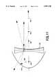
- FIG. 3shows a side cross sectional view of the divergent lens
- FIG. 4shows a front view of the divergent lens of FIG. 3
- FIG. 5shows a side cross sectional view of a preferred divergent Fresnel lens
- FIG. 6shows a front view of the divergent lens of FIG. 5
- FIG. 7shows a portion of a type 1 surface.
- FIG. 8shows an axial cross section of a schematic optical system.
- FIG. 9shows a portion of a type two surface.
- FIGS. 10, 11, 12, and 13,show axial cross sections of schematic optical systems
- FIG. 14shows a front view of a reflector
- FIG. 15shows a cross section, top view, of a preferred embodiment of a headlamp light source, reflector and a diverging Fresnel lens
- FIG. 16shows a sample angular luminous intensity distribution from the present invention (isocandella beam pattern).
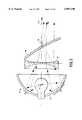
- FIG. 2shows a schematic cross section of a preferred embodiment of a vehicle headlamp 20.
- the headlamp 20may be formed with a light source 22, a reflector 24, and a diverging lens 26. Additionally a cover lens 28, housing, sealing, aiming and adjustment, attachment and support mechanisms (not shown) may he applied according to design choice as may be necessary and appropriate, as is generally understood in the art of lamp making.
- the light source 22may be any small optical light source, for example one typical of those commonly used in automotive designs. Tungsten filaments are commonly used as headlamp light sources, but electroded and electrodeless high intensity discharge sources may also he used.
- the preferred light source 22provides the necessary total number of lumens from a small volume to conveniently form a beam pattern. Useful light sources would include the typical 9004, 9005/6, 9007 and D1 type tungsten halogen lamp capsules. It is understood that a real light source is not a point source, so there is necessarily small spread of light around each ideal ray depending on the source size.
- FIG. 3shows a side cross sectional view of the divergent lens 26, and FIG. 4 shows a front view of the same divergent lens 26 of FIG. 3.
- the preferred lens materialis transparent, inexpensive, and has good optical and thermal properties, such as glass, acrylic, or one of a variety of high temperature plastics. Plastic may be accurately and inexpensively formed with relatively high quality optics. While it is possible to form a diverging lens 26 from glass, the preferred lens material is a clear polycarbonate plastic. For manufacturing simplicity, the preferred diverging lens 26 is rotationally symmetric about a central axis 34. Asymmetrical lenses may also be used.
- the diverging lens 26,(FIG. 2) has a first focal point 36 as understood and defined in the art of lens making.
- the first focal point 36, for a diverging lens 26is imaginary, and for a rotationally symmetric lens is located along the lens axis 34, and on a side of the lens 26 away from the light source 22, meaning here in the region on the forward side of the lens 26.
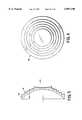
- FIG. 5shows a side cross sectional view of a preferred divergent Fresnel lens 38.
- FIG. 6shows a front view of the divergent Fresnel lens 38 of FIG. 5.
- the preferred Fresnel lens 38includes a smooth, concave surface 40 on a side facing the light source 22, and the reflector 24. On the side 41 facing away from light source 22, and the reflector 24, the side facing in the forward direction, the lens 38 includes several stepped, refractive regions, rotationally symmetric about a central axis 42 (concentric, divergent Fresnel lens).
- the reflector 24,(FIG. 2) may be made of an aluminized, molded plastic as is commonly done.
- the reflective surfaceis aligned to face the light source 22 and the lens 26 to reflect light from the light source 22 through the lens 26 in a forward direction.
- the reflector 24includes at least a first region 30, and a second region 32. Additional regions may also be included.
- the reflector 24is formed with at least a first region 30 taken from an ellipsoid of revolution (type 1 surface).
- FIG. 7shows a portion of an ellipsoid of revolution 46.
- the vertical axial cross section 48(XZ plane) is elliptical with a first focal point 50.
- a second focal-point 52is located along the X axis 54, forward of the first focal point 50.
- the horizontal axial cross section 56(XY plane) is also elliptical with a the same first focal point 50, and the same second focal point 52.
- Axial cross sections taken between the vertical and horizontalare similar. Light rays emitted at the first focal point 50 are then reflected towards the second focal point 52.
- FIG. 8shows a schematic diagram of an optical system arranged with these conditions. For an ellipsoid of revolution, the vertical and horizontal cross section are similar, so only one is discussed. Ray 58 emitted at the first focal point 60 is reflected on one side of the reflector 62 towards the second focal point 64 of the reflector 62. Ray 58 is refracted by the lens 66, similar to the way an incoming axial ray 68 (presented as a comparison standard) is refracted.
- Ray 58is therefore axially collimated, bringing ray 58 into parallel with the axis 70. Collimated rays, such as ray 58, can then be use to build the hot spot.
- the reflector 24(FIG. 2) further includes at least one region 32 taken from a second surface type.
- FIG. 9shows a portion of a type 2 surface 72.
- the vertical axial cross section 74(XZ plane) is elliptical with a first focal point 76.
- a second focal point 78is located along the X axis, forward of the first focal point 76.
- the horizontal axial cross section 80(XY plane) also has a first focal point located at the same first focal point 76.
- the horizontal axial cross section 80has a second focal point 82 located along the X axis, but not at the same position as the second focal point 78 associated with the vertical axial cross section 74. Second focal point 82 is then axially off set from the second focal point 78.
- the horizontal axial cross section 80may be elliptical, parabolic, or hyperbolic.
- Axial cross sections taken between the vertical and horizontalmay have forms with second focal points located between points 78 and 82.
- R y and R zare positive constants representing radii of curvature at the axial intersection of the surface (vertex) in the horizontal and vertical axial planes respectively.
- K y and K zare constants for the horizontal and vertical sectional curves, respectively, with K z greater than -1.
- the vertical axial cross sectionis then elliptical.
- the horizontal cross sectiondepending on the value of K y can be elliptical, parabolic or hyperbolic. Since a real light source has real dimension, R y and R z need not be exactly equal but may, for example, differ by approximately the size of the light source.
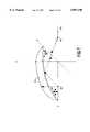
- FIGS. 10, 11, 12 and 13show schematic diagrams of optical systems regarding the horizontal axial plane of FIG. 9.
- ray 84 emitted at the first focal point 86 of the horizontal axial cross sectionis reflected on one side of the reflector 88 towards the second focal point 90 of the reflector 88 that is positioned between a light source at point 86 and the first focal point 92 of the lens 94.
- Ray 84is refracted by the lens 94, less than an amount sufficient to bring the ray 84 parallel to the axis 96.
- Light from the reflector 88is then directed across the axis 96, and not parallel the axis 96.
- ray 98 emitted at the first focal point 100 of the reflector 102is reflected on one side of the reflector 102 towards the second focal point 104 of the reflector 102 that is positioned beyond the first focal point 106 of the lens 108.
- Ray 98is refracted by the lens 108, more than an amount sufficient to bring the ray 98 parallel to the axis 110.
- Light from the reflectoris then directed away from the axis 110, and not parallel the axis 110 .
- ray 112 emitted at the first focal point 114 of the reflector 116is reflected on one side of the reflector 116 with a parabolic horizontal cross section towards a second focal point (not shown) located at infinity. Ray 112 is then diverged by the lens 118. Light from the reflector is then directed away from the axis 120, and not parallel the axis 120.
- ray 122 emitted at the first focal point 124 of the reflector 126is reflected on one side of the reflector 126 with a hyperbolic horizontal cross section away from a second focal point 128 (imaginary) located behind the reflector 126. Ray 122 is then diverged by the lens 130. Light from the reflector is then directed away from the axis 132, and not parallel the axis 132.
- the rays 84, 98, 112 and 122 in the horizontal axial plane 86are not collimated, and spread away from the lens axis.
- Vehicle beam patternsare irregularly shaped with some light needed low on the driver's side, little or no light high on the driver's side, good light in the center low, maximum light in the center just below straight on, and so forth. No single, simple surface provides a correct beam pattern. It is then the art of lamp building to construct beam patterns piecemeal from useful sections of reflectors. Headlamp design here is then carried out by forming one or more type 1 surfaces, and one or more type 2 surfaces, and then selecting sections of the each type and piecing them together to built a satisfactory beam pattern.
- FIG. 14shows a front view of a preferred embodiment of a reflector 134.
- the reflector 134shows a region 136 extending from the horizontal midline at the reflector center, symmetrically, upwards to the top edge of the reflector 134.
- a similar region 138extends from the horizontal midline to two points along the lower edge of the reflector 134.
- a third type 1 region 144is formed in a segment along the bottom edge of the reflector 134.
- Regions 140, 142, and 144are type 1 regions, portions of an ellipsoid of revolution.
- Regions 136 and 138are type 2 regions.
- the reflector and lensare fixed relative to each other.
- the fixed relationis easily accomplished by extending a rigid connection between the two, for example by extending a flange from the reflector, and a flange from the lens, and then rigidly linking the two flanges, for example by studs and bolts.
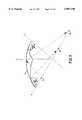
- FIG. 15shows a top cross sectional view of a preferred embodiment of a headlamp subassembly 146 with a light source, a reflector with type 1 and type 2 regions and a diverging lens. This is the same reflector 134 as seen in FIG. 14.
- a 9005 type head lamp capsule 148 with an axially aligned filament light source 150is coupled through the rear of a reflector 134.
- the reflector 134has two type two regions 136 (not shown) and 138 and three type 1 regions, 140, 142, and 144 within its reflective area.
- a reflector flange 152extends transverse to the lens axis. Attached to the reflector flange 152 are of forward projecting, screwed in place studs 154.
- the forward most ends of the studs 154are in turn attached to a lens flange 156.
- the lens flange 156also extends transverse to lens axis.
- the lens flange 156supports a lens 158 that includes a smooth, concave inside surfaced 160 facing the filament light source 150.
- the lens 158on the forward facing side, includes a stepped surface 162 with six, concentric stepped refractive rings.
- the lens 158is then a diverging, Fresnel type lens. The lens is located forward of the forward most portion of the reflector 134.
- the active portion of the lens 158has a dimension 164 that is less than a dimension 166 measured across the forward most, active portion of the reflector 134, with both dimensions being orthogonal through the lens axis, and parallel to each other.
- the lens 158is then smaller than the reflector 134 opening, while receiving all of the light reflected by the reflector 134.
- the lampmay be enclosed with a cover lens that may be any clear, and lens free (optically neutral), or nearly lens free cover.
- the preferred coveris made from a clear polycarbonate or similar material coated with abrasion resistant, and other protective coating as are generally known in the art.
- the cover lensmay be conveniently formed to meet chosen styling and aerodynamic requirements of the vehicle under design.
- the light sourceis positioned to be at or near the locus of first focal points of the reflector regions, so light emitted from the light source strikes the reflector in the type 1 region(s) and the type 2 region(s). Light is then directed from the type 1 region(s) towards the first focal point of the lens to he axially collimated. Light reflecting from the type 2 region(s) is directed horizontally, but either crosses or spreads away from the vertical axial plane. Light from the reflector type 2 region may then used to form the blend and spread regions of
- FIG. 16shows a sample angular luminous intensity distribution from the present invention (isocandella beam pattern).
- the beam patternwas the result of a headlamp with the structure shown in FIGS. 14 and 15.
- the reflectorwas made from a bulk molding plastic compound (BMC), and had a 113.3 millimeter (4.46 inch) inside diameter and a 46.5 millimeter (1.83 inch) axially dimension.
- the focal length of a type 1 region of the reflectorwas 25.0 millimeters (0.98 inches).
- the focal length of a type 2 region of the reflectorvaried from 23.2 millimeters (0.91 inches) to about 28.5 millimeters (1.12 inches).
- the light sourcewas a 65 watt halogen bulb (9005 vehicle bulb) with a tungsten filament positioned parallel to the optical axis of the lens.
- the Fresnel lenshad the shape of a circular dome molded from optical grade polycarbonate with a circular disk with two sideways extending flanges used for mounting.
- the lenshad an outer diameter of 90 millimeters (3.54 inches).
- the inside surface facing the reflectorwas a smooth, concave spherical surface having a radius of 100 millimeters (3.94 inches).
- the axial depth of the lenswas 13.4 millimeters (0.53 inches).
- the outer lens surfaceforward side, facing away from the reflector
- the lens thicknessvaried from 2.0 millimeters (0.08 inches) to 5.4 millimeters (0.21 inches).
- the geometrical definition of the refractive zoneswas as follows:
- the zonesrefer to the refractive diverging rings and are numbered from the inside ring 1 to the outside ring 6.
- R L2is the radius of curvature of respective torodial surface in the median section plane measured in millimeters.
- the h minis the minimum radial dimension measured in the median plane in millimeters.
- the h maxis the maximum radial dimension of the zone measured in the median plane millimeters.
- the lenswas aligned to be normal to the reflector axis with the lens center positioned 61.4 millimeters in front of the light source.
- the axial length of the lamp from the apex of the reflector to the outermost surface of the lenswas 88.2 millimeters (3.47 inches), while the weight of the unit was 0.26 kilograms.
- the diverging lenshad a negative focal length of approximately 110 millimeters, so that the axial dimension of the lamp was smaller than a projector type headlamp using a converging lens with a positive focal length of 110 millimeters. The difference was approximately twice the focal length, or 220 millimeters (8.7 inches).
- the reflectorhad five regions defined by the equation disclosed above and the following respective coefficient values:
- Each regionhad elliptical vertical axial cross sections.
- Regions 1, 2, 3, and 5had elliptical horizontal axial cross sections.
- Region 4had a hyperbolic horizontal axial cross section.
- FIG. 16shows a sample angular luminous intensity distribution (isocandella beam pattern) for the lamp assembly using the present invention.
- the beam pattern as shown in FIG. 16meets all of the existing required beam pattern limitations (FMVSS 108).
- FMVSS 108The disclosed dimensions, configurations and embodiments are as examples only, and other suitable configurations and relations may be used to implement the invention.
Landscapes
- Engineering & Computer Science (AREA)
- General Engineering & Computer Science (AREA)
- Non-Portable Lighting Devices Or Systems Thereof (AREA)
Abstract
Description
aX.sup.3 +bXY.sup.2 +cXZ.sup.2 +dX.sup.2 +eY.sup.2 +fZ.sup.2 +gX=0
______________________________________zone # R.sub.L2 (mm) h.sub.min (mm) h.sub.max (mm)______________________________________1 170 0.0 18.52 10,000 18.5 23.53 10,000 23.5 28.54 10,000 28.5 33.55 241.9 33.5 38.56 146.7 38.5 45.0______________________________________
______________________________________region R.sub.z mm R.sub.y mm K.sub.z K.sub.y______________________________________1 44.15 44.15 -0.587 -0.5872 44.15 44.15 -0.587 -0.5873 44.15 44.15 -0.587 -0.5874 49.67 47.00 -0.550 -1.0505 42.27 42.00 -0.600 -0.450______________________________________
Claims (11)
aX.sup.3 +bXY.sup.2 +cXZ.sup.2 +dX.sup.2 +eY.sup.2 +fZ.sup.2 +gX=0
Priority Applications (6)
| Application Number | Priority Date | Filing Date | Title |
|---|---|---|---|
| US08/625,618US5897196A (en) | 1996-03-29 | 1996-03-29 | Motor vehicle headlamp |
| EP97104844AEP0798506B1 (en) | 1996-03-29 | 1997-03-21 | Motor vehicle headlamp |
| DE69713199TDE69713199T2 (en) | 1996-03-29 | 1997-03-21 | Automotive headlamp |
| KR1019970010745AKR100438120B1 (en) | 1996-03-29 | 1997-03-27 | Car head lamp |
| CA002201205ACA2201205C (en) | 1996-03-29 | 1997-03-27 | Motor vehicle headlamp |
| JP9094514AJPH1031902A (en) | 1996-03-29 | 1997-03-31 | Head lamp for automobile |
Applications Claiming Priority (1)
| Application Number | Priority Date | Filing Date | Title |
|---|---|---|---|
| US08/625,618US5897196A (en) | 1996-03-29 | 1996-03-29 | Motor vehicle headlamp |
Publications (1)
| Publication Number | Publication Date |
|---|---|
| US5897196Atrue US5897196A (en) | 1999-04-27 |
Family
ID=24506885
Family Applications (1)
| Application Number | Title | Priority Date | Filing Date |
|---|---|---|---|
| US08/625,618Expired - LifetimeUS5897196A (en) | 1996-03-29 | 1996-03-29 | Motor vehicle headlamp |
Country Status (6)
| Country | Link |
|---|---|
| US (1) | US5897196A (en) |
| EP (1) | EP0798506B1 (en) |
| JP (1) | JPH1031902A (en) |
| KR (1) | KR100438120B1 (en) |
| CA (1) | CA2201205C (en) |
| DE (1) | DE69713199T2 (en) |
Cited By (25)
| Publication number | Priority date | Publication date | Assignee | Title |
|---|---|---|---|---|
| WO2000006419A1 (en)* | 1998-07-31 | 2000-02-10 | Federal-Mogul Corporation | Electrodeless neon light module for vehicle lighting systems |
| US6123440A (en)* | 1997-12-05 | 2000-09-26 | Valeo Vision | Automobile headlight and optical unit with hyperbolic reflector and plano-convex or toric convergent lens |
| US20020145370A1 (en)* | 2001-01-22 | 2002-10-10 | Ichikoh Industries, Ltd. | Lamp device for vehicle |
| US20030137753A1 (en)* | 2002-01-22 | 2003-07-24 | Yoshiyuki Takase | Lens supporting structure |
| US20050030759A1 (en)* | 2003-08-04 | 2005-02-10 | Guide Corporation | Bifocal hyperbolic catadioptric collection system for an automotive lamp |
| US20050047135A1 (en)* | 2003-08-01 | 2005-03-03 | Greg Rhoads | Apparatus and method of using light sources of differing wavelengths in an unitized beam |
| US6866408B1 (en)* | 1999-02-09 | 2005-03-15 | Valeo Vision | Motor vehicle headlamp of the elliptical type capable of emitting a beam without cut-off |
| US20050073849A1 (en)* | 2003-10-06 | 2005-04-07 | Greg Rhoads | Light source using light emitting diodes and an improved method of collecting the energy radiating from them |
| US20050083699A1 (en)* | 2003-08-12 | 2005-04-21 | Greg Rhoads | Apparatus and method for using emitting diodes (LED) in a side-emitting device |
| US20050219840A1 (en)* | 2004-03-30 | 2005-10-06 | Holder Ronald G | Apparatus and method for improved illumination area fill |
| US20060139933A1 (en)* | 2004-12-29 | 2006-06-29 | Industrial Technology Research Institute | Reflector with negative focal length |
| US20070076419A1 (en)* | 2005-10-05 | 2007-04-05 | Trident Lighting L.L.C. | Vehicular light assembly and related method |
| US20070177382A1 (en)* | 2001-10-03 | 2007-08-02 | Led Pipe | Solid state light source |
| US7950821B1 (en) | 2007-10-26 | 2011-05-31 | Georgitsis Anthony C | Auxiliary lighting systems |
| WO2011156647A1 (en)* | 2010-06-11 | 2011-12-15 | Intematix Corporation | Led spotlight |
| US20120243250A1 (en)* | 2011-03-23 | 2012-09-27 | Koito Manufacturing Co., Ltd. | Vehicular illumination lamp |
| US8325055B2 (en) | 2003-05-19 | 2012-12-04 | Donnelly Corporation | Mirror assembly for vehicle |
| CN103032815A (en)* | 2011-10-06 | 2013-04-10 | 黑拉许克联合股份有限公司 | Optical transform device |
| US20160018068A1 (en)* | 2014-07-16 | 2016-01-21 | PlayNitride Inc. | Optical module |
| US20170211774A1 (en)* | 2014-07-23 | 2017-07-27 | Myotek Pacific Corp. | Fog lamp lens and assembly |
| US10066801B1 (en) | 2017-10-04 | 2018-09-04 | Osram Sylvania Inc. | Vehicle lamp reflector having ventilation channel adjacent lamp capsule |
| US20180266640A1 (en)* | 2017-03-13 | 2018-09-20 | Valeo Vision | Light device, in particular a lighting and/or signalling device, for a motor vehicle |
| US20180345846A1 (en)* | 2017-05-31 | 2018-12-06 | Grote Industries, Inc. | Electric lamp having a cover with a light guide |
| CN114137783A (en)* | 2021-12-23 | 2022-03-04 | 广景视睿科技(深圳)有限公司 | Projection lens and projector |
| US11383856B2 (en)* | 2018-12-04 | 2022-07-12 | SZ DJI Technology Co., Ltd. | Lampshade structures, unmanned aerial vehicle arms, unmanned aerial vehicles, and movable platforms |
Families Citing this family (3)
| Publication number | Priority date | Publication date | Assignee | Title |
|---|---|---|---|---|
| EP1055869A3 (en)* | 1999-05-28 | 2002-03-06 | Corning Incorporated | Glass lens for automotive lighting |
| JP2002216511A (en)* | 2001-01-22 | 2002-08-02 | Ichikoh Ind Ltd | Vehicle headlights |
| SI21894A (en)* | 2004-09-17 | 2006-04-30 | Hella Lux Slovenija, Proizvodnja Svetlobne Opremeza Motorna In Druga Vozila, D.O.O. | Collecting lens for a projection headlight within a vehicle |
Citations (9)
| Publication number | Priority date | Publication date | Assignee | Title |
|---|---|---|---|---|
| US1393573A (en)* | 1920-10-21 | 1921-10-11 | John A Ritter | Headlamp |
| US1758041A (en)* | 1928-05-23 | 1930-05-13 | Heymann Bruno | Light projector |
| DE535657C (en)* | 1931-01-21 | 1931-10-14 | Ver Eisenbahn Signalwerke G M | Device for continuous train control |
| CH188367A (en)* | 1934-01-25 | 1936-12-31 | Richard Dietrich Friedrich | Headlight with an ellipsoidal reflector. |
| DE656609C (en)* | 1935-10-29 | 1938-02-09 | Friedrich Richard Dietrich | Electric headlight |
| US4066887A (en)* | 1976-10-27 | 1978-01-03 | Maurice Levis | Segmented sectional reflection for the projection of light beams and its method of production |
| US5014166A (en)* | 1988-10-15 | 1991-05-07 | Carello Lighting Plc | Light unit |
| US5440456A (en)* | 1993-05-08 | 1995-08-08 | Robert Bosch Gmbh | Headlight for vehicles |
| US5450294A (en)* | 1992-08-29 | 1995-09-12 | Robert Bosch Gmbh | Headlight for vehicles |
Family Cites Families (8)
| Publication number | Priority date | Publication date | Assignee | Title |
|---|---|---|---|---|
| GB320693A (en)* | 1929-04-08 | 1929-10-24 | Sidney Philip Holloway | An improvement in glare free headlamps for motor cars, lorries and similar vehicles |
| GB584666A (en)* | 1939-05-11 | 1947-01-21 | Machal Projecteurs | Improvements in or relating to light projectors |
| FR2210157A6 (en)* | 1972-12-08 | 1974-07-05 | Laribe Armand | |
| DE3334459C2 (en)* | 1983-09-23 | 1993-10-21 | Bosch Gmbh Robert | Low beam headlight reflector for motor vehicles |
| JPH01232602A (en)* | 1988-03-11 | 1989-09-18 | Koito Mfg Co Ltd | Head light for car |
| JP2517383B2 (en)* | 1989-02-17 | 1996-07-24 | 株式会社小糸製作所 | Vehicle headlights |
| SK277928B6 (en)* | 1992-12-21 | 1995-08-09 | Miroslav Hanecka | Lighting system for lighting fittings, projecting and enlargement mechanism |
| JPH07159897A (en)* | 1993-12-07 | 1995-06-23 | Nippondenso Co Ltd | Light source device |
- 1996
- 1996-03-29USUS08/625,618patent/US5897196A/ennot_activeExpired - Lifetime
- 1997
- 1997-03-21EPEP97104844Apatent/EP0798506B1/ennot_activeExpired - Lifetime
- 1997-03-21DEDE69713199Tpatent/DE69713199T2/ennot_activeExpired - Lifetime
- 1997-03-27KRKR1019970010745Apatent/KR100438120B1/ennot_activeExpired - Lifetime
- 1997-03-27CACA002201205Apatent/CA2201205C/ennot_activeExpired - Lifetime
- 1997-03-31JPJP9094514Apatent/JPH1031902A/enactivePending
Patent Citations (9)
| Publication number | Priority date | Publication date | Assignee | Title |
|---|---|---|---|---|
| US1393573A (en)* | 1920-10-21 | 1921-10-11 | John A Ritter | Headlamp |
| US1758041A (en)* | 1928-05-23 | 1930-05-13 | Heymann Bruno | Light projector |
| DE535657C (en)* | 1931-01-21 | 1931-10-14 | Ver Eisenbahn Signalwerke G M | Device for continuous train control |
| CH188367A (en)* | 1934-01-25 | 1936-12-31 | Richard Dietrich Friedrich | Headlight with an ellipsoidal reflector. |
| DE656609C (en)* | 1935-10-29 | 1938-02-09 | Friedrich Richard Dietrich | Electric headlight |
| US4066887A (en)* | 1976-10-27 | 1978-01-03 | Maurice Levis | Segmented sectional reflection for the projection of light beams and its method of production |
| US5014166A (en)* | 1988-10-15 | 1991-05-07 | Carello Lighting Plc | Light unit |
| US5450294A (en)* | 1992-08-29 | 1995-09-12 | Robert Bosch Gmbh | Headlight for vehicles |
| US5440456A (en)* | 1993-05-08 | 1995-08-08 | Robert Bosch Gmbh | Headlight for vehicles |
Cited By (54)
| Publication number | Priority date | Publication date | Assignee | Title |
|---|---|---|---|---|
| US6123440A (en)* | 1997-12-05 | 2000-09-26 | Valeo Vision | Automobile headlight and optical unit with hyperbolic reflector and plano-convex or toric convergent lens |
| US6118226A (en)* | 1998-07-31 | 2000-09-12 | Federal-Mogul World Wide, Inc. | Electrodeless neon light module for vehicle lighting systems |
| WO2000006419A1 (en)* | 1998-07-31 | 2000-02-10 | Federal-Mogul Corporation | Electrodeless neon light module for vehicle lighting systems |
| US6866408B1 (en)* | 1999-02-09 | 2005-03-15 | Valeo Vision | Motor vehicle headlamp of the elliptical type capable of emitting a beam without cut-off |
| US20020145370A1 (en)* | 2001-01-22 | 2002-10-10 | Ichikoh Industries, Ltd. | Lamp device for vehicle |
| US6811289B2 (en)* | 2001-01-22 | 2004-11-02 | Ichikoh Industries, Ltd. | Lamp device for a vehicle having a free curved surface and a lens without a prism |
| US20070177382A1 (en)* | 2001-10-03 | 2007-08-02 | Led Pipe | Solid state light source |
| US20030137753A1 (en)* | 2002-01-22 | 2003-07-24 | Yoshiyuki Takase | Lens supporting structure |
| US6728048B2 (en)* | 2002-01-22 | 2004-04-27 | Fuji Photo Optical Co., Ltd. | Lens supporting structure |
| US8325055B2 (en) | 2003-05-19 | 2012-12-04 | Donnelly Corporation | Mirror assembly for vehicle |
| US20050047135A1 (en)* | 2003-08-01 | 2005-03-03 | Greg Rhoads | Apparatus and method of using light sources of differing wavelengths in an unitized beam |
| US7083304B2 (en) | 2003-08-01 | 2006-08-01 | Illumination Management Solutions, Inc. | Apparatus and method of using light sources of differing wavelengths in an unitized beam |
| US20050030759A1 (en)* | 2003-08-04 | 2005-02-10 | Guide Corporation | Bifocal hyperbolic catadioptric collection system for an automotive lamp |
| US20050083699A1 (en)* | 2003-08-12 | 2005-04-21 | Greg Rhoads | Apparatus and method for using emitting diodes (LED) in a side-emitting device |
| US7246917B2 (en) | 2003-08-12 | 2007-07-24 | Illumination Management Solutions, Inc. | Apparatus and method for using emitting diodes (LED) in a side-emitting device |
| WO2005041254A3 (en)* | 2003-10-06 | 2005-06-23 | Illumination Man Solutions Inc | Improved light source using light emitting diodes and an improved method of collecting the energy radiating from them |
| US20050073849A1 (en)* | 2003-10-06 | 2005-04-07 | Greg Rhoads | Light source using light emitting diodes and an improved method of collecting the energy radiating from them |
| US6986593B2 (en)* | 2003-10-06 | 2006-01-17 | Illumination Management Solutions, Inc. | Method and apparatus for light collection, distribution and zoom |
| US20090043544A1 (en)* | 2004-03-30 | 2009-02-12 | Illumination Management Solutions Inc. | Apparatus and method for improved illumination area fill |
| US20050219840A1 (en)* | 2004-03-30 | 2005-10-06 | Holder Ronald G | Apparatus and method for improved illumination area fill |
| US7591570B2 (en) | 2004-03-30 | 2009-09-22 | Cooper Technologies Company | Apparatus and method for improved illumination area fill |
| US20070076414A1 (en)* | 2004-03-30 | 2007-04-05 | Holder Ronald G | Apparatus and method for improved illumination area fill |
| US7172319B2 (en) | 2004-03-30 | 2007-02-06 | Illumination Management Solutions, Inc. | Apparatus and method for improved illumination area fill |
| US7581855B2 (en) | 2004-03-30 | 2009-09-01 | Cooper Technologies Company | Apparatus and method for improved illumination area fill |
| US7438447B2 (en) | 2004-03-30 | 2008-10-21 | Illumination Management Solutions Inc. | Apparatus and method for improved illumination area fill |
| US20090021945A1 (en)* | 2004-03-30 | 2009-01-22 | Illumination Management Solutions Inc. | Apparatus and method for improved illumination area fill |
| US7217010B2 (en)* | 2004-12-29 | 2007-05-15 | Industrial Technology Research Institute | Reflector with negative focal length |
| US20060139933A1 (en)* | 2004-12-29 | 2006-06-29 | Industrial Technology Research Institute | Reflector with negative focal length |
| US7252421B2 (en)* | 2005-10-05 | 2007-08-07 | A & L Assembly, Llc | Vehicular light assembly and related method |
| US20070076419A1 (en)* | 2005-10-05 | 2007-04-05 | Trident Lighting L.L.C. | Vehicular light assembly and related method |
| US7950821B1 (en) | 2007-10-26 | 2011-05-31 | Georgitsis Anthony C | Auxiliary lighting systems |
| US20110194287A1 (en)* | 2007-10-26 | 2011-08-11 | Georgitsis Antony C | Auxiliary lighting systems |
| USD656258S1 (en) | 2007-10-26 | 2012-03-20 | Vision Motor Sports | Lighting unit |
| USRE46220E1 (en) | 2007-10-26 | 2016-11-29 | Vision Motor Sports, Inc. | Auxiliary lighting systems |
| US8277077B2 (en) | 2007-10-26 | 2012-10-02 | Georgitsis Antony C | Auxiliary lighting systems |
| US8888318B2 (en) | 2010-06-11 | 2014-11-18 | Intematix Corporation | LED spotlight |
| WO2011156647A1 (en)* | 2010-06-11 | 2011-12-15 | Intematix Corporation | Led spotlight |
| CN103003624A (en)* | 2010-06-11 | 2013-03-27 | 英特曼帝克司公司 | LED spotlight |
| US9482401B2 (en)* | 2011-03-23 | 2016-11-01 | Koito Manufacturing Co., Ltd. | Vehicular illumination lamp |
| US20120243250A1 (en)* | 2011-03-23 | 2012-09-27 | Koito Manufacturing Co., Ltd. | Vehicular illumination lamp |
| EP2503226B1 (en)* | 2011-03-23 | 2017-01-04 | Koito Manufacturing Co., Ltd. | Vehicular illumination lamp |
| CN103032815A (en)* | 2011-10-06 | 2013-04-10 | 黑拉许克联合股份有限公司 | Optical transform device |
| CN103032815B (en)* | 2011-10-06 | 2017-08-22 | 黑拉许克联合股份有限公司 | Optical transform device |
| US20160018068A1 (en)* | 2014-07-16 | 2016-01-21 | PlayNitride Inc. | Optical module |
| US10240741B2 (en)* | 2014-07-23 | 2019-03-26 | Myotek Holdings, Inc. | Fog lamp lens and assembly |
| US20170211774A1 (en)* | 2014-07-23 | 2017-07-27 | Myotek Pacific Corp. | Fog lamp lens and assembly |
| US10533722B2 (en)* | 2017-03-13 | 2020-01-14 | Valeo Vision | Light device, in particular a lighting and/or signaling device, for a motor vehicle |
| US20180266640A1 (en)* | 2017-03-13 | 2018-09-20 | Valeo Vision | Light device, in particular a lighting and/or signalling device, for a motor vehicle |
| CN108571703A (en)* | 2017-03-13 | 2018-09-25 | 法雷奥照明公司 | For the lighting device of motor vehicles, especially illumination and/or signal indicating device |
| US20180345846A1 (en)* | 2017-05-31 | 2018-12-06 | Grote Industries, Inc. | Electric lamp having a cover with a light guide |
| US10569693B2 (en)* | 2017-05-31 | 2020-02-25 | Grote Industries, Inc. | Electric lamp having a cover with a light guide |
| US10066801B1 (en) | 2017-10-04 | 2018-09-04 | Osram Sylvania Inc. | Vehicle lamp reflector having ventilation channel adjacent lamp capsule |
| US11383856B2 (en)* | 2018-12-04 | 2022-07-12 | SZ DJI Technology Co., Ltd. | Lampshade structures, unmanned aerial vehicle arms, unmanned aerial vehicles, and movable platforms |
| CN114137783A (en)* | 2021-12-23 | 2022-03-04 | 广景视睿科技(深圳)有限公司 | Projection lens and projector |
Also Published As
| Publication number | Publication date |
|---|---|
| DE69713199T2 (en) | 2003-02-13 |
| CA2201205C (en) | 2004-08-31 |
| EP0798506A2 (en) | 1997-10-01 |
| EP0798506A3 (en) | 1998-11-11 |
| KR970066254A (en) | 1997-10-13 |
| CA2201205A1 (en) | 1997-09-29 |
| DE69713199D1 (en) | 2002-07-18 |
| JPH1031902A (en) | 1998-02-03 |
| EP0798506B1 (en) | 2002-06-12 |
| KR100438120B1 (en) | 2005-05-24 |
Similar Documents
| Publication | Publication Date | Title |
|---|---|---|
| US5897196A (en) | Motor vehicle headlamp | |
| US4811174A (en) | Vehicle lighting device | |
| US5438485A (en) | Illuminator for use with a remote light source | |
| US5103381A (en) | Lamp reflector system | |
| JP3005954B2 (en) | Lamp | |
| JP3005955B2 (en) | Lamp | |
| KR102048876B1 (en) | Headlamp featuring both low-beam and high-beam outputs and devoid of moving parts | |
| US4517630A (en) | Motor vehicle headlight with condensing lens and diaphragm | |
| US4494176A (en) | Lamps having multiple and aimed parabolic sections for increased useful light output | |
| EP0854316B1 (en) | Projector type lamp | |
| JP4044352B2 (en) | head lamp | |
| KR20170034392A (en) | Fog lamp lenses and assemblies | |
| US6367954B1 (en) | Multi-lens projector lamp | |
| US7121704B2 (en) | Vehicle headlamp | |
| US4945455A (en) | Automotive projector-type headlamp | |
| US5373430A (en) | Wide angle beam pattern lamp | |
| JPH02270202A (en) | Automobile head lamp | |
| US20060209556A1 (en) | Vehicle lamp | |
| JPH03266301A (en) | Lamp assembly | |
| CA1172682A (en) | Reflector lamp | |
| JP4154651B2 (en) | Lamp and projection lens | |
| CN217785016U (en) | Reflector, projection assembly, lamp and vehicle | |
| JP4262370B2 (en) | Lamp | |
| US4520433A (en) | Motor vehicle headlamp | |
| RU2009390C1 (en) | Auxiliary head-light automobile lamp |
Legal Events
| Date | Code | Title | Description |
|---|---|---|---|
| AS | Assignment | Owner name:OSRAM SYLVANIA INC., MASSACHUSETTS Free format text:ASSIGNMENT OF ASSIGNORS INTEREST;ASSIGNORS:DOROGI, MICHAEL J.;SOSKIND, YAKOV G.;REEL/FRAME:007955/0362 Effective date:19960328 | |
| AS | Assignment | Owner name:VALEO SYLVANIA LLC, INDIANA Free format text:ASSIGNMENT OF ASSIGNORS INTEREST;ASSIGNOR:OSRAM SYLVANIA PRODUCTS INC.;REEL/FRAME:009064/0624 Effective date:19971231 Owner name:OSRAM SYLVANIA PRODUCTS INC., MASSACHUSETTS Free format text:ASSIGNMENT OF ASSIGNORS INTEREST;ASSIGNOR:OSRAM SYLVANIA INC.;REEL/FRAME:009064/0639 Effective date:19971231 | |
| STCF | Information on status: patent grant | Free format text:PATENTED CASE | |
| FPAY | Fee payment | Year of fee payment:4 | |
| FPAY | Fee payment | Year of fee payment:8 | |
| FPAY | Fee payment | Year of fee payment:12 | |
| AS | Assignment | Owner name:OSRAM SYLVANIA INC., MASSACHUSETTS Free format text:MERGER;ASSIGNOR:OSRAM SYLVANIA INC.;REEL/FRAME:025549/0400 Effective date:20100902 |