US5896414A - Method and apparatus for providing control channel communications for an information distribution system - Google Patents
Method and apparatus for providing control channel communications for an information distribution systemDownload PDFInfo
- Publication number
- US5896414A US5896414AUS08/718,075US71807596AUS5896414AUS 5896414 AUS5896414 AUS 5896414AUS 71807596 AUS71807596 AUS 71807596AUS 5896414 AUS5896414 AUS 5896414A
- Authority
- US
- United States
- Prior art keywords
- message
- information
- messages
- control channel
- upstream
- Prior art date
- Legal status (The legal status is an assumption and is not a legal conclusion. Google has not performed a legal analysis and makes no representation as to the accuracy of the status listed.)
- Expired - Lifetime
Links
Images


Classifications
- H—ELECTRICITY
- H04—ELECTRIC COMMUNICATION TECHNIQUE
- H04L—TRANSMISSION OF DIGITAL INFORMATION, e.g. TELEGRAPHIC COMMUNICATION
- H04L65/00—Network arrangements, protocols or services for supporting real-time applications in data packet communication
- H04L65/40—Support for services or applications
- H—ELECTRICITY
- H04—ELECTRIC COMMUNICATION TECHNIQUE
- H04H—BROADCAST COMMUNICATION
- H04H20/00—Arrangements for broadcast or for distribution combined with broadcast
- H04H20/38—Arrangements for distribution where lower stations, e.g. receivers, interact with the broadcast
- H—ELECTRICITY
- H04—ELECTRIC COMMUNICATION TECHNIQUE
- H04L—TRANSMISSION OF DIGITAL INFORMATION, e.g. TELEGRAPHIC COMMUNICATION
- H04L5/00—Arrangements affording multiple use of the transmission path
- H04L5/14—Two-way operation using the same type of signal, i.e. duplex
- H—ELECTRICITY
- H04—ELECTRIC COMMUNICATION TECHNIQUE
- H04N—PICTORIAL COMMUNICATION, e.g. TELEVISION
- H04N21/00—Selective content distribution, e.g. interactive television or video on demand [VOD]
- H04N21/20—Servers specifically adapted for the distribution of content, e.g. VOD servers; Operations thereof
- H04N21/21—Server components or server architectures
- H04N21/226—Characteristics of the server or Internal components of the server
- H—ELECTRICITY
- H04—ELECTRIC COMMUNICATION TECHNIQUE
- H04N—PICTORIAL COMMUNICATION, e.g. TELEVISION
- H04N21/00—Selective content distribution, e.g. interactive television or video on demand [VOD]
- H04N21/20—Servers specifically adapted for the distribution of content, e.g. VOD servers; Operations thereof
- H04N21/23—Processing of content or additional data; Elementary server operations; Server middleware
- H04N21/238—Interfacing the downstream path of the transmission network, e.g. adapting the transmission rate of a video stream to network bandwidth; Processing of multiplex streams
- H04N21/2383—Channel coding or modulation of digital bit-stream, e.g. QPSK modulation
- H—ELECTRICITY
- H04—ELECTRIC COMMUNICATION TECHNIQUE
- H04N—PICTORIAL COMMUNICATION, e.g. TELEVISION
- H04N21/00—Selective content distribution, e.g. interactive television or video on demand [VOD]
- H04N21/20—Servers specifically adapted for the distribution of content, e.g. VOD servers; Operations thereof
- H04N21/23—Processing of content or additional data; Elementary server operations; Server middleware
- H04N21/239—Interfacing the upstream path of the transmission network, e.g. prioritizing client content requests
- H—ELECTRICITY
- H04—ELECTRIC COMMUNICATION TECHNIQUE
- H04N—PICTORIAL COMMUNICATION, e.g. TELEVISION
- H04N21/00—Selective content distribution, e.g. interactive television or video on demand [VOD]
- H04N21/20—Servers specifically adapted for the distribution of content, e.g. VOD servers; Operations thereof
- H04N21/23—Processing of content or additional data; Elementary server operations; Server middleware
- H04N21/24—Monitoring of processes or resources, e.g. monitoring of server load, available bandwidth, upstream requests
- H04N21/2408—Monitoring of the upstream path of the transmission network, e.g. client requests
- H—ELECTRICITY
- H04—ELECTRIC COMMUNICATION TECHNIQUE
- H04N—PICTORIAL COMMUNICATION, e.g. TELEVISION
- H04N21/00—Selective content distribution, e.g. interactive television or video on demand [VOD]
- H04N21/40—Client devices specifically adapted for the reception of or interaction with content, e.g. set-top-box [STB]; Operations thereof
- H04N21/43—Processing of content or additional data, e.g. demultiplexing additional data from a digital video stream; Elementary client operations, e.g. monitoring of home network or synchronising decoder's clock; Client middleware
- H04N21/437—Interfacing the upstream path of the transmission network, e.g. for transmitting client requests to a VOD server
- H—ELECTRICITY
- H04—ELECTRIC COMMUNICATION TECHNIQUE
- H04N—PICTORIAL COMMUNICATION, e.g. TELEVISION
- H04N21/00—Selective content distribution, e.g. interactive television or video on demand [VOD]
- H04N21/40—Client devices specifically adapted for the reception of or interaction with content, e.g. set-top-box [STB]; Operations thereof
- H04N21/43—Processing of content or additional data, e.g. demultiplexing additional data from a digital video stream; Elementary client operations, e.g. monitoring of home network or synchronising decoder's clock; Client middleware
- H04N21/438—Interfacing the downstream path of the transmission network originating from a server, e.g. retrieving encoded video stream packets from an IP network
- H04N21/4382—Demodulation or channel decoding, e.g. QPSK demodulation
- H—ELECTRICITY
- H04—ELECTRIC COMMUNICATION TECHNIQUE
- H04N—PICTORIAL COMMUNICATION, e.g. TELEVISION
- H04N21/00—Selective content distribution, e.g. interactive television or video on demand [VOD]
- H04N21/60—Network structure or processes for video distribution between server and client or between remote clients; Control signalling between clients, server and network components; Transmission of management data between server and client, e.g. sending from server to client commands for recording incoming content stream; Communication details between server and client
- H04N21/65—Transmission of management data between client and server
- H04N21/658—Transmission by the client directed to the server
- H04N21/6581—Reference data, e.g. a movie identifier for ordering a movie or a product identifier in a home shopping application
- H—ELECTRICITY
- H04—ELECTRIC COMMUNICATION TECHNIQUE
- H04N—PICTORIAL COMMUNICATION, e.g. TELEVISION
- H04N7/00—Television systems
- H04N7/16—Analogue secrecy systems; Analogue subscription systems
- H04N7/173—Analogue secrecy systems; Analogue subscription systems with two-way working, e.g. subscriber sending a programme selection signal
- H04N7/17309—Transmission or handling of upstream communications
- H—ELECTRICITY
- H04—ELECTRIC COMMUNICATION TECHNIQUE
- H04H—BROADCAST COMMUNICATION
- H04H60/00—Arrangements for broadcast applications with a direct linking to broadcast information or broadcast space-time; Broadcast-related systems
- H04H60/76—Arrangements characterised by transmission systems other than for broadcast, e.g. the Internet
- H04H60/81—Arrangements characterised by transmission systems other than for broadcast, e.g. the Internet characterised by the transmission system itself
- H04H60/93—Wired transmission systems
Definitions
- the inventionrelates to information distribution systems and, more particularly, to a method and apparatus for providing control channel communications for an information distribution system.
- control information to facilitate operation of the set-top terminal within the subscriber's homeis typically sent as control packets within the video data stream.
- These control packetscontain certain header information which enables the set-top terminal to differentiate between video data and control data. Consequently, the use of packets for sending control data through the video data channel inherently reduces the amount of bandwidth that is available for transmitting video information to the subscriber.
- control information that is sent from the set-top terminal to the service provideris typically sent via the telephone system.
- the subscriberis required to have a dedicated telephone line to provide interactive functionality for the video system.
- the low data rate of the telephone systemdoes not permit extensive communications between the set-top terminal and the service provider.
- these systemsgenerally provide rudimentary control commands such as selection of a service or particular information via a menu on the subscriber's television screen.
- the present inventionprovides independent communications channels for bi-directional message traffic between a service provider and a set-top terminal.
- messages, control information, and status informationare transmitted between the service provider and the subscriber's set-top terminal using an independent channel that is different from the channel used for sending requested information such as movies from the service provider to the subscriber's home.
- the inventionprovides one downstream data channel and two upstream channels.
- the downstream channelconnects the service provider to the set-top terminal via a channel having a data rate of approximately 750 kbps per second.
- the two upstream data channelsconnect the set-top terminal to the service provider, each have an effective data rate of approximately 43.5 kbps per second.
- an information distribution systemgenerally contains an information server that is connected to a forward data communications channel having a high bandwidth that carries video information from the server to a subscriber's set-top terminal.
- the servergenerally contains a bus structure for carrying command and control information.
- An illustrative bus structureis a VME bus.
- the present inventionconnects to the VME bus through a VME bus interface. Messages, control information and status information that are to be handled by a specific modem are extracted from the VME bus by the VME bus interface and passed to a message buffer and status register. After buffering, a message processor and router produces messages that are addressed to a particular set-top terminal. These messages are then transmitted to a modulator that quadrature modulates the message information onto a carrier which is then propagated through a power amplifier onto a cable network.
- Messages from the set-top terminalare demodulated by a pair of demodulators which extract the messages from the two upstream data channels.
- the upstream datais also quadrature modulated onto a carrier frequency that is processed by the demodulators to extract the message information.
- the message information from each of the demodulatorsis passed to the message processor and router which then sends the messages to the message buffer where they await the VME bus interface to pass the messages from the set-top terminal to the service provider's server.
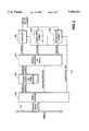
- FIG. 1depicts a high-level block diagram of an interactive information distribution system that incorporates the present invention
- FIG. 2depicts a high-level block diagram of the control channel modem of the present invention
- FIG. 3depicts a block diagram of the VME interface
- FIG. 4is a block diagram of the message buffer and status register
- FIG. 5is a block diagram of the message processor
- FIG. 6is a block diagram of the modulator
- FIG. 7depicts a block diagram of a first demodulator.
- FIG. 1depicts a high-level block diagram of an interactive information distribution system 100.
- the system 100contains service provider equipment 102 connected to a plurality of subscriber equipment 108 via both a forward information distribution channel 104 and a plurality of bi-directional control channels 106 containing a unidirectional upstream control channel and a unidirectional downstream control channel.
- a subscriberby interacting with the subscriber equipment 102 located in their home, may request information via the control channel 106 from the service provider's equipment 102.
- the requested informationis transmitted from the service provider equipment 102 through the forward information distribution channel 104 to the subscriber equipment 108 that requested the information.
- the subscribermay request a particular movie via the control channel, and the service provider equipment will retrieve that movie from memory and "play" the movie through the forward information distribution channel 104 for display on the subscriber's equipment 108.
- Movie selection information, status messages and control messagesare sent from the service provider's equipment 102 through the control channel 106 (the unidirectional upstream control channel) to the subscriber's equipment 108.
- Responses to those messages, as well as queries for the service provider's equipmentare sent from the subscriber's equipment 108 through the control channels 106 (the unidirectional downstream control channel) to the service provider equipment 102. Consequently, the system depicted in FIG. 1 is a fully interactive, real-time information distribution system.
- service provider equipment 102contains an information server 110, a network interface and modulator 112, a control channel modem 114 and a control bus 116 which interconnects the information server 110, the network interface and modulator 112 and the control channel modem 114.
- a plurality of network interface and modulator circuits 112 and a plurality of control channel modems 114are incorporated within the service provider equipment 102.
- Control channel modem 114interprets these commands and places the received control and message information upon the control bus 116.
- This informationis transmitted to either the information server or the network interface and modulator to control the information that is being sent to the particular set-top terminal that has requested that information.
- the information serverin response to the control information from the subscriber, executes certain software which may, for example, generate particular menus for the subscriber to select certain information or send particular information requested by the subscriber.
- a plurality of high-data rate channelsconnect the server to the network interface and modulator 112.
- the network interface and modulatortakes each of the data streams that are transmitted on these channels and packetizes those data streams into a format that is compatible with the forward information distribution channel.
- packetizationconforms to a particular transmission standard such as the Moving Pictures Experts Group (MPEG) standard for video information transport.
- MPEGMoving Pictures Experts Group
- ATMasynchronous transfer mode
- Certain messagesmay be sent to the subscriber equipment for display. These messages are passed from the server, through the control bus to the control channel modem and sent on an upstream control channel to the subscriber equipment 108.
- the forward information distribution channel and the control channelare frequency multiplexed onto a coaxial cable network which may be hybrid fiber-coax cable network and the like.
- the subscriber equipment 108generally contains a set-top terminal 118, an input device 120 and a display device 122.
- the set-top terminalcontains electronics which interact with both the control channels and the information distribution channel as well as processing input commands from the input device.
- the input device 120is typically a remote control unit that interacts with the set-top terminal 118 via either an RF or an IR link.
- the display 122is typically a conventional television or monitor.
- the set-top terminaldemodulates and processes the information from the distribution channel as well as control channel information. In addition, it processes the control information from the input device and appropriately transmits that information via the upstream control channel to the control channel modem within the service provide equipment.
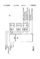
- FIG. 2depicts a block diagram of the control channel modem 114 of FIG. 1.
- the control channel modem 114contains a bus interface (e.g., a VME bus interface), message buffers and status registers 202, a message processor and router 204, a modulator 206, and a pair of demodulators 208 and 210.
- the bus interfaceis connected to the control bus 116.
- One such bus appropriate for this applicationis a VME bus which is well-known in the art for carrying messages, control information and status information between digital devices.
- the bus interfaceextracts information from the bus that is addressed by the server to a particular control channel modem.
- the messagesare temporarily stored in a plurality of message buffers and status registers 202. At appropriate times, the message buffers and status registers are emptied, and their information is passed to the message processor and router 204. Additionally, certain reset and interrupt information may be sent via the VME bus to the control channel modem. This information is generally not buffered and is directly passed from the VME bus interface to the message processor and router 204 for immediate execution.
- Upstream messagesare passed from the message processor and router 204 to the modulator 206.
- the modulatorquadrature modulates a carrier with the message information and couples the modulated carrier to the upstream control channel. The particular frequency used for transmitting a particular message is controlled by the server. Thus, this information is carried by the control bus and interpreted by the bus interface which couples the frequency control information to the modulator.
- Downstream informationis supplied from the control channels to the pair of demodulators 208 and 210.
- a pair of demodulatorsis used to reduce the probability of a message collision at the modem.
- Each demodulatoris a quadrature demodulator which extracts the message information from the control channel and couples that message information to the message processor and router 204. This message information is then buffered within the message buffers and status registers 202 and ultimately passed to the bus interface 200 which couples the message information to the control bus 116 for communication to the information server or the network interface and modulator.
- FIG. 3depicts a detailed block diagram of the bus interface 200, in particular, a VME bus interface.
- This bus interfaceprovides the interface between the control channel modem 114 and the control bus 116. All communications between the control channel modem and the control bus take place as memory-mapped operations within the control bus interface 200.
- the interface 200supports the following VME bus modes: A16, D16 (word dated transfers) for registers and buffers, and D8 (EO) (byte data transfers) for buffers.
- the bus interface 200contains data transceivers 300, interrupt controller 302, slave controller 304, interrupt vector generator 306, a field programmable gate array (FPGA) 308, a base address generator 310, and a delay generator 312.
- FPGAfield programmable gate array
- the interrupt controlleris a VME 3000 (VME bus interrupt generator) available from PLX Technology.
- the slave controlleris a VME 2000 "VME bus slave module interface device" also available from PLX technology.
- the data transceiver 300, the interrupt controller 302 and the slave controller 304are each connected directly to the VME bus.
- the slave controller 304monitors the VME data transfer bus signals to determine the type of access being performed.
- the slave controller 304produces data strobes and acknowledge information that is coupled to the FPGA 308.
- the gate array 308(available from Altera) interprets the data strobes using an address comparator to insure that the access that is being requested is appropriate. Unsupported access attempts are ignored by the FPGA.
- the gate arraydrives the local address bus, enables the data transceivers, and provides the appropriate select and enable signals for either register or RAM accesses.
- the gate arraythen acknowledges the access to the VME bus through the slave controller 304.
- the interrupt controller 302accepts a single level local interrupt from the control channel modem. When a local interrupt is detected by the interrupt controller, the controller generates an interrupt to the VME bus, and handles the resulting interrupt arbitration via the VME priority interrupt bus.
- the interrupt controloperates in an ROAC (Reset On Acknowledge) mode, and the VME interrupt is cleared upon response from the VME controller.
- the interrupt controllerprovides the VME controller with an 8-bit interrupt vector via the data bus.
- the interrupt controller 302is coupled via the enable port of the interrupt vector generator 306 such that upon enabling the interrupt vector generator, the vector is placed on the data bus for the data transceivers to couple to the VME bus.
- the VME bus addressingis coupled directly to the FPGA. The FPGA is discussed further with respect to FIG. 5.
- FIG. 4depicts a block diagram of the message buffers and status registers 202.
- the registers and buffersand implemented using a 16-bit wide dual-port RAM 400.
- the RAM 400contains complete pairs of input/output ports, including RAM busy, chip select, read/write, output enable, upper byte select, lower byte select, address and data.
- a complete set of portsare connected to the VME bus interface and the message processor. As such, both of these units may access the dual port RAM simultaneously.
- This RAMis partitioned into two buffer pages; one for each modulator and demodulator, and the memory contains a status register for each page.
- the status registeris used to inform the server if a page is available to be written (has already been transmitted), and if the modulator is generating an interrupt. An interrupt may be generated when a demodulator buffer page becomes available for transfer to the server.
- the demodulator buffer pagealso has a status register associated with it. This register contains information regarding messages that have been received from the subscriber equipment.
- the status registercontains a number of fields including a field that indicates when the buffer is available for writing, a field that indicates when a new message has been deposited in the buffer, an indicator bit that is set whenever a dropped message could not be placed into the buffer, an overflow error field which indicates that a message has been received that is longer than the specification permits and that the message has been truncated, and a length field that indicates the length of the received message in bytes.
- the servervia the VME interface and the message processor are synchronized such that, for each subsystem, one device accesses buffer page 0 while the other subsystem accesses the buffer page 1.
- the devicestoggle which page they are using. This approach provides the maximum processing time to each device, and minimizes the likelihood of an access collision within the memory.
- both the server and the message processorwould access the same status register.
- the message processormay poll the modulator status register to check for a new message while the server is updating the status.
- the arbitration capabilities of the memoryare utilized. If the memory reports a busy condition, the access by the message processor is held off by use of the DTACK signal, while accesses via the VME bus are held off by a delay of the VMEACK signal by the VME bus interface.
- Such access controlis handled by the programmable gate array 308 of FIG. 3 in conjunction with the delay generator 312 that delays the access signal from the VME bus when the RAM busy flag is high.
- FIG. 5depicts a block diagram of the message processor and router 204 of FIG. 2.
- the message processor and router 204contains a microcontroller 500, a flash read-only memory (ROM) 502, a static random access memory (RAM) 504, and a field programmable gate array (FPGA) 506.
- the purpose of the message processor and routeris to read and format outgoing messages from the message buffers and send them to the modulator, and accept incoming messages from either demodulator and transfer those messages to the message buffer.
- the microcontrolleris connected to the message buffer to control read/write, output enable and chip select functions.
- the DTACK signalis coupled from FPGA 308 of FIG. 3 to the microcontroller 500.
- the DTACK signalis decoded from the "Ready" signal of the dual-port RAM. If the RAM is ready, a DTACK is generated. If it is not ready, the DTACK is delayed until the RAM is Ready. For other registers which are not shared with other devices (i.e., not held within the Dual-Port RAM), the ready signal is always active.
- the microcontroller's data busis connected to the modulator and both demodulators as well as to the ROM 502, RAM 504, and FPGA 506.
- the address bus for the microcontrolleris also connected to the ROM, RAM, and FPGA, as well as to the message buffer (400 of FIG. 4).
- the FPGA 506forms an interface between the microcontroller and the demodulators as well as the VME interface bus. Specifically, FPGA 506 generates demodulator FIFO read and output enable signals and modulator write enable signals. Also, modulator and demodulator FIFO status signals from the modulators and demodulators are coupled directly to the microcontroller.
- the FPGAgenerally contains the reset and interrupt registers used by the VME interface that are not contained within the buffer memory. Note that access to either the reset or interrupt register by the VME bus initiates a level four interrupt to the microcontroller. This interrupt may be disabled via a physical jumper on the circuit board.
- an illustrative microcontroller useful in the present inventionis a 68306 microcontroller available from Motorola.
- the reset and interrupt registersare used to enable the server through the VME bus to completely reset the control channel modem as well as independently interrupt and reset certain components of the control channel modem such as the modulator or either demodulator.
- FIG. 6depicts a block diagram of modulator 206.
- the modulatorcontains a first-in/first-out (FIFO) buffer 600 for outgoing message traffic, a forward error correction (FEC) processor 602, shaping filter 604, a frequency agile synthesizer 606, a quadrature phase shift key (QPSK) vector modulator 608, a driver amplifier 610, and a channel filter 612.
- the FIFO 600receives data from the message processor in the form of a series of messages that are placed within serial memory locations within the FIFO.
- a status lineis connected from the FIFO to the message processor to inform the microcontroller of the FIFO status, i.e., whether the FIFO can accept further data for buffering.
- the FIFO 600is connected to the FEC processor 602 by two paths.
- the first pathis a read path that connects an address generator within the FEC processor to the FIFO to request specific data from the FIFO memory. That data is passed on a data path between the FIFO and the FEC processor 602.
- the FEC processorin a conventional manner, generates quadrature data, i.e., in-phase data (I-DATA) and quadrature data (Q-DATA) that is coupled to the shaping filters 604.
- the I and Q dataalso contains the forward error correction coding that facilitates effective error correction of the received data by the demodulator within the set-top terminal.
- Each message that is placed in the FIFOcontains 184 bytes of data.
- these messages(message blocks) contain eight set-top terminal messages of 23 bytes each, and any messages that are unused within a block are filled with zeros to fulfill the 184 byte requirement.
- Each 23 byte messagecontains two bytes for an address of a set-top terminal, one byte for a message length indicator, one byte for a control indicator, one byte for a sequence number, and 18 bytes of data.
- the message processoralso appends to each message a 4-byte header before the message is transferred to the FIFO.
- the headeris a transport protocol header, e.g., an MPEG transport packet header.
- the I- and Q-data streamshave bit rates of 500 kbps.
- the FEC processoris illustratively a Xilinx programmable FEC device 614 combined with Altera field programmable gate array (FPGA) 616 and a 32K ⁇ 8 RAM 618.
- the FPGAprovides two functions in support of the FEC device. Since the FEC device 614 is serial in nature, the first function of the FPGA 616 is to read data from the FIFO 600 and convert the byte-wide data to a serial stream. This stream is transferred under control of the FEC device 614 which periodically stops the stream in order to insert an FEC check sum. The second function of the FPGA 616 is to convert the serial stream produced by the FEC device 614 to I- and Q-data streams.
- the FEC device 614performs the functions of scrambling, interleaving and Reed-Solomon forward error correction coding the data.
- the RAM 618is used by the FEC device 614 during interleaving. Every 94 bytes (twice per packet), the incoming data stream is halted and two bytes of FEC coding are incorporated into the data stream.
- the dual data streamsare passed through shaping filters 604 prior to modulation.
- These filtersare based on a four-pole Bessel design, as an approximation to a raised cosine passband shape.
- the 50% point of the filteris at 650 kHz, providing 30% excess bandwidth for 500 kbps data streams.
- a varactor-tuned phase lock loop (PLL) synthesizer 606is provided.
- the frequency of modulationis set by the server via a memory-mapped register within one of the FPGAs. Alternatively, the frequencies are stored in the dual-port RAM.
- the resolution of frequency selectionis 2 MHz, meaning that incrementing the register value by one increases the modulation frequency by 2 MHz.
- Valid settings for this registerare 35 to 65 (decimal) resulting in a frequency range of 70 to 130 MHz.
- Modulation of the I and Q data streamsis accomplished by a monolithic, QPSK vector modulator 608.
- One such commercially available modulatoris the HPMX-2005 manufactured by Hewlett Packard. This modulator is followed by an HPMX-3002 drive amplifier 610, which provides up to 23 dBm of saturated output power. The specific gain of this device is set by an adjustment on the circuit board.
- the QPSK vector modulator 608conventionally modulates the synthesizer frequency with the I-data and Q-data provided by the shaping filters 604.
- the drive amplifier 610then amplifies the RF modulated QPSK signal and couples the amplified signal to a channel filter 612. As such, the amplified signal is filtered to eliminate spurious energy outside the frequency band of 70 to 130 MHz.
- This filteris a passive bandpass device, based on a 3 pole Butterworth filter.
- FIG. 7depicts one of the two demodulators 208 and 210 in block diagram form. Both demodulators are identical.
- the channel filter 700 that is located at the input of the demodulatoris shared by both the demodulators 208 and 210. This is the only component of the demodulators that is shared.
- the demodulator 208contains a channel filter 700, an AGC amplifier 702 and its control circuitry 704, a frequency mixer 706, an anti-alias filter 708, a frequency agile synthesizer 710, an analog-to-digital (A/D) converter (ADC) 712, gate array 714, digital signal processor (DSP) 716, and an output buffer FIFO 718.
- the channel filter 700limits the frequencies that are presented to the demodulator subsystem.
- This filteris a third order Butterworth device with 3 dB points at 7.5 and 15 MHz. Its input impedance is 75 ohms. While this filter removes interfering signals outside the allowable uplink frequency range it does not affect any signals within the allowable uplink band.
- the channel filteris immediately followed by an automatic gain control amplifier 702 which is used to maintain a constant amplitude signal into the A/D converter 712.
- the AGC circuit 704samples the signal of the input of the A/D converter 716. Circuit 704 produces a gain control signal in response to the magnitude of the sample and couple the gain control signal to the AGC amplifier 702.
- the AGC amplifier 702is replaced with a simple clamp (hard limiter) that limits the signal magnitude coupled to the mixer 706.
- the AGC amplifieris followed by a mixer 706 that performs a direct down conversion to near baseband of the received signal.
- the mixer 706performs the function of an I only demodulator. Since the local oscillator 710 is not locked to the incoming signal it is quite possible that received information is in quadrature with this oscillator. Since the incoming data stream is received at 62.5 kilobits per second, down converting the signal to a center frequency of 62.5 KHz allows the I/Q separation to be accomplished in the DSP processor.
- the mixer 706is followed by an anti-aliasing filter 708 prior to the analog to digital converter (ADC). This filter is a low pass, fifth order Butterworth device with a flat response to 130 KHz, and a loss of 29 dB at 260 KHz.
- Conversion of the anti-aliasing filter's outputis provided by an 8-bit ADC under control of the digital signal processor 716.
- the DSP's timeris set to generate pulses at the desired sample rate of 255 ksps. These pulses are interpreted by the field program gate array 714 and initiate a conversion by the ADC. Once conversion is complete, the result is held in the FPGA 714 until the data is read by the DSP 716. If the DSP 716 requests the data before conversion is complete, DSP operation is delayed via memory wait state insertion until the conversion is complete.
- the digital signal processoris a TMS320C30 manufactured by Texas Instruments.
- this DSPdemodulates the I and Q components of the input data signal, maintains a symbol alignment using a timing loop and performs carrier recovery which derotates the incoming signal.
- the resulting bit streamis then processed to locate message headers which determine message alignment. Once the message has been identified it is written to the FIFO 718 for transfer to the message processor in byte format. An additional bit is also written to the FIFO to indicate a start of a message.
- the datais presented from the FIFO to the message processor in byte wide quantities with an additional bit indicating start of message.
- a start bitis connected to input D15 of the microcontroller data bus while the data bits are connected to pins D7-D0.
- Incoming messagesare variable in length and may consist of 7 to 23 bytes. Note that any channel synchronization headers have been stripped off by the demodulator.
- the demodulator message formatis similar to the modulator message format and contains an address field having a two byte length that identifies the set-top terminal that sends the message, a message length field of one byte, a control field of one byte, a sequence field of one byte, a data field having a variable number of bytes (the maximum being 16 bytes), and a CRC field having two bytes.
- the message processormonitors the status of the demodulator FIFOs 718 via their empty and almost empty flags to determine the presence of incoming messages. If a message is received, the message processor first checks the status register for the currently selected message buffer to determine if it is available. If it is available, the message processor begins transferring bytes from the FIFO 718 to the message buffer. Since the uplink data rate is quite slow, the message processor must take care as not to underflow the FIFO 718 during the transfer.
- the message processorchecks the value of the length field in the incoming data. This field indicates to the message processor the length of message including the control, sequence, data, and CRC fields. Since messages are variable in length this value is used to determine how many bytes to transfer from the FIFO. The start of message bit may be used as confirmation as to message length, but is not available until the next message is received. Note that the CRC field value is transferred directly to the message buffer and its validity is not checked by the message processor. The validity is checked by a server subsystem or network interface.
- Valid values for the length byteare 4 through 20. If a message having a length of greater than 20 is received, the message transfer is truncated after 23 bytes, and the start of message bit must be used to resynchronize the next incoming message.
- the status register for the message bufferis updated.
- the buffer available for write bitis cleared, the interrupt pending bit is set, and the length field is set to total message length, e.g., received message length plus 3 bytes as defined by the transport protocol. Additionally, an appropriate bit in the interrupt register is set to indicate whether an interrupt is pending for either demodulator or the modulator. If the message has been truncated, the overflow bit is also set.
- the message processorchecks the demodulators other buffer for availability. This permits recovery if toggle synchronization with the server is lost. If indeed neither buffer is available, the message processor disposes of the incoming messages and updates the demodulator status register by setting the message dropped bit. The message processor also insures that the interrupt pending bits in the status register and interrupt register are set.
Landscapes
- Engineering & Computer Science (AREA)
- Signal Processing (AREA)
- Multimedia (AREA)
- Computer Networks & Wireless Communication (AREA)
- Communication Control (AREA)
- Small-Scale Networks (AREA)
- Mobile Radio Communication Systems (AREA)
- Telephonic Communication Services (AREA)
Abstract
Description
Claims (12)
Priority Applications (8)
| Application Number | Priority Date | Filing Date | Title |
|---|---|---|---|
| US08/718,075US5896414A (en) | 1996-09-17 | 1996-09-17 | Method and apparatus for providing control channel communications for an information distribution system |
| AT97944437TATE285635T1 (en) | 1996-09-17 | 1997-09-16 | METHOD AND DEVICE FOR CONTROL CHANNEL COMMUNICATION OF AN INFORMATION DISTRIBUTION SYSTEM |
| DE69732035TDE69732035T2 (en) | 1996-09-17 | 1997-09-16 | METHOD AND DEVICE FOR CONTROL CHANNEL COMMUNICATION OF AN INFORMATION DISTRIBUTION SYSTEM |
| JP51501698AJP3840267B2 (en) | 1996-09-17 | 1997-09-16 | Method and apparatus for providing control channel communication for an information distribution system |
| PCT/US1997/017177WO1998012823A1 (en) | 1996-09-17 | 1997-09-16 | Method and apparatus for providing control channel communications for an information distribution system |
| KR1019997002265AKR100560334B1 (en) | 1996-09-17 | 1997-09-16 | Method and apparatus for providing control channel communications for an information distribution system |
| EP97944437AEP0920739B9 (en) | 1996-09-17 | 1997-09-16 | Method and apparatus for providing control channel communications for an information distribution system |
| CA002265954ACA2265954C (en) | 1996-09-17 | 1997-09-16 | Method and apparatus for providing control channel communications for an information distribution system |
Applications Claiming Priority (1)
| Application Number | Priority Date | Filing Date | Title |
|---|---|---|---|
| US08/718,075US5896414A (en) | 1996-09-17 | 1996-09-17 | Method and apparatus for providing control channel communications for an information distribution system |
Publications (1)
| Publication Number | Publication Date |
|---|---|
| US5896414Atrue US5896414A (en) | 1999-04-20 |
Family
ID=24884731
Family Applications (1)
| Application Number | Title | Priority Date | Filing Date |
|---|---|---|---|
| US08/718,075Expired - LifetimeUS5896414A (en) | 1996-09-17 | 1996-09-17 | Method and apparatus for providing control channel communications for an information distribution system |
Country Status (8)
| Country | Link |
|---|---|
| US (1) | US5896414A (en) |
| EP (1) | EP0920739B9 (en) |
| JP (1) | JP3840267B2 (en) |
| KR (1) | KR100560334B1 (en) |
| AT (1) | ATE285635T1 (en) |
| CA (1) | CA2265954C (en) |
| DE (1) | DE69732035T2 (en) |
| WO (1) | WO1998012823A1 (en) |
Cited By (59)
| Publication number | Priority date | Publication date | Assignee | Title |
|---|---|---|---|---|
| US6112274A (en)* | 1998-06-17 | 2000-08-29 | Intel Corporation | Method and apparatus for processing more than one interrupts without reinitializing the interrupt handler program |
| US6112232A (en)* | 1998-01-27 | 2000-08-29 | Phasecom Ltd. | Data communication device for CATV networks |
| WO2001049031A1 (en)* | 1999-12-29 | 2001-07-05 | Sony Electronics Inc. | Intelligent transceiving method, device and system |
| WO2001056179A1 (en)* | 2000-01-26 | 2001-08-02 | Vyyo, Ltd. | Programmable phy for broadband wireless access systems |
| WO2001056180A1 (en)* | 2000-01-26 | 2001-08-02 | Vyyo, Ltd. | Two-dimensional scheduling scheme for a broadband wireless access system |
| US20010036841A1 (en)* | 2000-01-26 | 2001-11-01 | Vyyo Ltd. | Power inserter configuration for wireless modems |
| US20010051512A1 (en)* | 2000-01-26 | 2001-12-13 | Vyyo Ltd. | Redundancy scheme for the radio frequency front end of a broadband wireless hub |
| US20010053180A1 (en)* | 2000-01-26 | 2001-12-20 | Vyyo, Ltd. | Offset carrier frequency correction in a two-way broadband wireless access system |
| US20020024975A1 (en)* | 2000-03-14 | 2002-02-28 | Hillel Hendler | Communication receiver with signal processing for beam forming and antenna diversity |
| US20020024967A1 (en)* | 1999-12-14 | 2002-02-28 | Zaun David Brian | Dynamic configuration of input filtering parameters for an MPEG re-multiplexer |
| US20020052205A1 (en)* | 2000-01-26 | 2002-05-02 | Vyyo, Ltd. | Quality of service scheduling scheme for a broadband wireless access system |
| US20020056132A1 (en)* | 2000-01-26 | 2002-05-09 | Vyyo Ltd. | Distributed processing for optimal QOS in a broadband access system |
| US20020054068A1 (en)* | 2000-03-31 | 2002-05-09 | United Video Properties, Inc. | Systems and methods for reducing cut-offs in program recording |
| US20020059621A1 (en)* | 2000-10-11 | 2002-05-16 | Thomas William L. | Systems and methods for providing storage of data on servers in an on-demand media delivery system |
| US6473858B1 (en) | 1999-04-16 | 2002-10-29 | Digeo, Inc. | Method and apparatus for broadcasting data with access control |
| US20020159511A1 (en)* | 2000-01-26 | 2002-10-31 | Vyyo Ltd. | Transverter control mechanism for a wireless modem in a broadband access system |
| US6498821B2 (en) | 2000-01-26 | 2002-12-24 | Vyyo, Ltd. | Space diversity method and system for broadband wireless access |
| US20030093799A1 (en)* | 2001-11-14 | 2003-05-15 | Kauffman Marc W. | Streamed content Delivery |
| US6567118B1 (en)* | 2000-10-27 | 2003-05-20 | Scientific-Atlanta, Inc. | Frequency agile adaptive automatic gain control circuit |
| US20030195948A1 (en)* | 1996-10-31 | 2003-10-16 | Naoya Takao | Data transmission/reception apparatus for use in a two-way digital broadcasting system |
| US6636890B1 (en)* | 1997-11-28 | 2003-10-21 | International Business Machines Corporation | Stand-alone internet mailbox for cable subscribers |
| US20030198240A1 (en)* | 2002-04-17 | 2003-10-23 | Edmundo Rojas | Data-receiving port and method for programmable updating of available buffer space information in a communications channel |
| US6751723B1 (en)* | 2000-09-02 | 2004-06-15 | Actel Corporation | Field programmable gate array and microcontroller system-on-a-chip |
| US20050169255A1 (en)* | 1999-04-16 | 2005-08-04 | Tsutomu Shimomura | Methods and apparatus for broadcasting data |
| US6987754B2 (en) | 2000-03-07 | 2006-01-17 | Menashe Shahar | Adaptive downstream modulation scheme for broadband wireless access systems |
| US7051111B1 (en) | 2000-04-25 | 2006-05-23 | Digeo, Inc. | Multiple source proxy management system |
| US20060271980A1 (en)* | 1997-04-21 | 2006-11-30 | Mankovitz Roy J | Method and apparatus for time-shifting video and text in a text-enhanced television program |
| US20070079342A1 (en)* | 2005-09-30 | 2007-04-05 | Guideworks, Llc | Systems and methods for managing local storage of on-demand content |
| US20070220024A1 (en)* | 2004-09-23 | 2007-09-20 | Daniel Putterman | Methods and apparatus for integrating disparate media formats in a networked media system |
| US20080140231A1 (en)* | 1999-07-14 | 2008-06-12 | Philips Solid-State Lighting Solutions, Inc. | Methods and apparatus for authoring and playing back lighting sequences |
| US20080209465A1 (en)* | 2000-10-11 | 2008-08-28 | United Video Properties, Inc. | Systems and methods for supplementing on-demand media |
| US20100186034A1 (en)* | 2005-12-29 | 2010-07-22 | Rovi Technologies Corporation | Interactive media guidance system having multiple devices |
| US7826752B1 (en)* | 2005-06-02 | 2010-11-02 | Level 3 Communications, Llc | Optical transmission apparatuses, methods, and systems |
| US20110022620A1 (en)* | 2009-07-27 | 2011-01-27 | Gemstar Development Corporation | Methods and systems for associating and providing media content of different types which share atrributes |
| US20110026469A1 (en)* | 2009-07-31 | 2011-02-03 | Chih-Hsiang Wu | Method of Handling P-TMSI Change in a Wireless Communication System and Related Communication Device |
| US20110029690A1 (en)* | 2008-03-13 | 2011-02-03 | Mbda France | Data routing system |
| US20110167449A1 (en)* | 1996-05-03 | 2011-07-07 | Starsight Telecast Inc. | Information system |
| US20110197233A1 (en)* | 1999-07-16 | 2011-08-11 | Woo Hyun Paik | Broadcasting service system using mobile communication terminal |
| US8255961B2 (en) | 2000-10-11 | 2012-08-28 | United Video Properties, Inc. | Systems and methods for caching data in media-on-demand systems |
| US8607287B2 (en) | 2005-12-29 | 2013-12-10 | United Video Properties, Inc. | Interactive media guidance system having multiple devices |
| US20150046998A1 (en)* | 2013-08-08 | 2015-02-12 | Silicon Safe Limited | Secure data storage |
| US9014546B2 (en) | 2009-09-23 | 2015-04-21 | Rovi Guides, Inc. | Systems and methods for automatically detecting users within detection regions of media devices |
| US9021538B2 (en) | 1998-07-14 | 2015-04-28 | Rovi Guides, Inc. | Client-server based interactive guide with server recording |
| US9071872B2 (en) | 2003-01-30 | 2015-06-30 | Rovi Guides, Inc. | Interactive television systems with digital video recording and adjustable reminders |
| US9125169B2 (en) | 2011-12-23 | 2015-09-01 | Rovi Guides, Inc. | Methods and systems for performing actions based on location-based rules |
| US9161087B2 (en) | 2000-09-29 | 2015-10-13 | Rovi Technologies Corporation | User controlled multi-device media-on-demand system |
| US9166714B2 (en) | 2009-09-11 | 2015-10-20 | Veveo, Inc. | Method of and system for presenting enriched video viewing analytics |
| US9191722B2 (en) | 1997-07-21 | 2015-11-17 | Rovi Guides, Inc. | System and method for modifying advertisement responsive to EPG information |
| US9311405B2 (en) | 1998-11-30 | 2016-04-12 | Rovi Guides, Inc. | Search engine for video and graphics |
| US9319735B2 (en) | 1995-06-07 | 2016-04-19 | Rovi Guides, Inc. | Electronic television program guide schedule system and method with data feed access |
| US9326025B2 (en) | 2007-03-09 | 2016-04-26 | Rovi Technologies Corporation | Media content search results ranked by popularity |
| US9326016B2 (en) | 2007-07-11 | 2016-04-26 | Rovi Guides, Inc. | Systems and methods for mirroring and transcoding media content |
| US9426509B2 (en) | 1998-08-21 | 2016-08-23 | Rovi Guides, Inc. | Client-server electronic program guide |
| US9674563B2 (en) | 2013-11-04 | 2017-06-06 | Rovi Guides, Inc. | Systems and methods for recommending content |
| US9681105B2 (en) | 2005-12-29 | 2017-06-13 | Rovi Guides, Inc. | Interactive media guidance system having multiple devices |
| US9848161B2 (en) | 2003-04-21 | 2017-12-19 | Rovi Guides, Inc. | Video recorder having user extended and automatically extended time slots |
| US9973817B1 (en) | 2005-04-08 | 2018-05-15 | Rovi Guides, Inc. | System and method for providing a list of video-on-demand programs |
| US10063934B2 (en) | 2008-11-25 | 2018-08-28 | Rovi Technologies Corporation | Reducing unicast session duration with restart TV |
| US10673564B1 (en)* | 2018-09-21 | 2020-06-02 | Xilinx, Inc. | Software defined modem |
Families Citing this family (2)
| Publication number | Priority date | Publication date | Assignee | Title |
|---|---|---|---|---|
| KR100658870B1 (en)* | 2000-11-18 | 2006-12-15 | 엘지전자 주식회사 | Dynamic Service Transmission Method |
| CN100401727C (en)* | 2002-12-04 | 2008-07-09 | 华为技术有限公司 | A Method of Communication Between Modules in Distributed System |
Citations (3)
| Publication number | Priority date | Publication date | Assignee | Title |
|---|---|---|---|---|
| US4688248A (en)* | 1983-10-31 | 1987-08-18 | Clarion Co., Ltd. | Pay television system |
| US5355162A (en)* | 1993-07-13 | 1994-10-11 | Pacific Ray Video Limited | Multi-standard cable television system |
| US5625651A (en)* | 1994-06-02 | 1997-04-29 | Amati Communications, Inc. | Discrete multi-tone data transmission system using an overhead bus for synchronizing multiple remote units |
- 1996
- 1996-09-17USUS08/718,075patent/US5896414A/ennot_activeExpired - Lifetime
- 1997
- 1997-09-16JPJP51501698Apatent/JP3840267B2/ennot_activeExpired - Fee Related
- 1997-09-16EPEP97944437Apatent/EP0920739B9/ennot_activeExpired - Lifetime
- 1997-09-16KRKR1019997002265Apatent/KR100560334B1/ennot_activeExpired - Fee Related
- 1997-09-16DEDE69732035Tpatent/DE69732035T2/ennot_activeExpired - Lifetime
- 1997-09-16CACA002265954Apatent/CA2265954C/ennot_activeExpired - Fee Related
- 1997-09-16WOPCT/US1997/017177patent/WO1998012823A1/enactiveIP Right Grant
- 1997-09-16ATAT97944437Tpatent/ATE285635T1/ennot_activeIP Right Cessation
Patent Citations (3)
| Publication number | Priority date | Publication date | Assignee | Title |
|---|---|---|---|---|
| US4688248A (en)* | 1983-10-31 | 1987-08-18 | Clarion Co., Ltd. | Pay television system |
| US5355162A (en)* | 1993-07-13 | 1994-10-11 | Pacific Ray Video Limited | Multi-standard cable television system |
| US5625651A (en)* | 1994-06-02 | 1997-04-29 | Amati Communications, Inc. | Discrete multi-tone data transmission system using an overhead bus for synchronizing multiple remote units |
Cited By (121)
| Publication number | Priority date | Publication date | Assignee | Title |
|---|---|---|---|---|
| US9319735B2 (en) | 1995-06-07 | 2016-04-19 | Rovi Guides, Inc. | Electronic television program guide schedule system and method with data feed access |
| US9423936B2 (en) | 1996-05-03 | 2016-08-23 | Rovi Guides, Inc. | Information system |
| US8806538B2 (en) | 1996-05-03 | 2014-08-12 | Starsight Telecast, Inc. | Information system |
| US9027058B2 (en) | 1996-05-03 | 2015-05-05 | Rovi Guides, Inc. | Information system |
| US20110167449A1 (en)* | 1996-05-03 | 2011-07-07 | Starsight Telecast Inc. | Information system |
| US8646005B2 (en) | 1996-05-03 | 2014-02-04 | Starsight Telecast, Inc. | Information system |
| US20030195948A1 (en)* | 1996-10-31 | 2003-10-16 | Naoya Takao | Data transmission/reception apparatus for use in a two-way digital broadcasting system |
| US20060271980A1 (en)* | 1997-04-21 | 2006-11-30 | Mankovitz Roy J | Method and apparatus for time-shifting video and text in a text-enhanced television program |
| US9113122B2 (en) | 1997-04-21 | 2015-08-18 | Rovi Guides, Inc. | Method and apparatus for time-shifting video and text in a text-enhanced television program |
| US9191722B2 (en) | 1997-07-21 | 2015-11-17 | Rovi Guides, Inc. | System and method for modifying advertisement responsive to EPG information |
| US6636890B1 (en)* | 1997-11-28 | 2003-10-21 | International Business Machines Corporation | Stand-alone internet mailbox for cable subscribers |
| US6112232A (en)* | 1998-01-27 | 2000-08-29 | Phasecom Ltd. | Data communication device for CATV networks |
| US6112274A (en)* | 1998-06-17 | 2000-08-29 | Intel Corporation | Method and apparatus for processing more than one interrupts without reinitializing the interrupt handler program |
| US9055318B2 (en) | 1998-07-14 | 2015-06-09 | Rovi Guides, Inc. | Client-server based interactive guide with server storage |
| US9232254B2 (en) | 1998-07-14 | 2016-01-05 | Rovi Guides, Inc. | Client-server based interactive television guide with server recording |
| US10075746B2 (en) | 1998-07-14 | 2018-09-11 | Rovi Guides, Inc. | Client-server based interactive television guide with server recording |
| US9055319B2 (en) | 1998-07-14 | 2015-06-09 | Rovi Guides, Inc. | Interactive guide with recording |
| US9226006B2 (en) | 1998-07-14 | 2015-12-29 | Rovi Guides, Inc. | Client-server based interactive guide with server recording |
| US9154843B2 (en) | 1998-07-14 | 2015-10-06 | Rovi Guides, Inc. | Client-server based interactive guide with server recording |
| US9021538B2 (en) | 1998-07-14 | 2015-04-28 | Rovi Guides, Inc. | Client-server based interactive guide with server recording |
| US9118948B2 (en) | 1998-07-14 | 2015-08-25 | Rovi Guides, Inc. | Client-server based interactive guide with server recording |
| US9426509B2 (en) | 1998-08-21 | 2016-08-23 | Rovi Guides, Inc. | Client-server electronic program guide |
| US9311405B2 (en) | 1998-11-30 | 2016-04-12 | Rovi Guides, Inc. | Search engine for video and graphics |
| US20050169255A1 (en)* | 1999-04-16 | 2005-08-04 | Tsutomu Shimomura | Methods and apparatus for broadcasting data |
| US8701140B2 (en) | 1999-04-16 | 2014-04-15 | Arris Enterprises, Inc. | Methods and apparatus for broadcasting data |
| US7155734B1 (en) | 1999-04-16 | 2006-12-26 | Digeo, Inc. | Methods of operating a data broadcast service |
| US6473858B1 (en) | 1999-04-16 | 2002-10-29 | Digeo, Inc. | Method and apparatus for broadcasting data with access control |
| US20080140231A1 (en)* | 1999-07-14 | 2008-06-12 | Philips Solid-State Lighting Solutions, Inc. | Methods and apparatus for authoring and playing back lighting sequences |
| US20110197233A1 (en)* | 1999-07-16 | 2011-08-11 | Woo Hyun Paik | Broadcasting service system using mobile communication terminal |
| US8443405B2 (en)* | 1999-07-16 | 2013-05-14 | Lg Electronics Inc. | Broadcasting service system using mobile communication terminal |
| US20020024967A1 (en)* | 1999-12-14 | 2002-02-28 | Zaun David Brian | Dynamic configuration of input filtering parameters for an MPEG re-multiplexer |
| WO2001049031A1 (en)* | 1999-12-29 | 2001-07-05 | Sony Electronics Inc. | Intelligent transceiving method, device and system |
| KR100788629B1 (en)* | 1999-12-29 | 2007-12-27 | 소니 일렉트로닉스 인코포레이티드 | Intelligent sending and receiving methods, devices and systems |
| US6757909B1 (en) | 1999-12-29 | 2004-06-29 | Sony Corporation | Internet set-top box having an in-band tuner and cable modem |
| US6498821B2 (en) | 2000-01-26 | 2002-12-24 | Vyyo, Ltd. | Space diversity method and system for broadband wireless access |
| US20010036841A1 (en)* | 2000-01-26 | 2001-11-01 | Vyyo Ltd. | Power inserter configuration for wireless modems |
| US7123650B2 (en) | 2000-01-26 | 2006-10-17 | Vyyo, Inc. | Offset carrier frequency correction in a two-way broadband wireless access system |
| WO2001056179A1 (en)* | 2000-01-26 | 2001-08-02 | Vyyo, Ltd. | Programmable phy for broadband wireless access systems |
| US7149188B2 (en) | 2000-01-26 | 2006-12-12 | Vyyo, Inc. | Distributed processing for optimal QOS in a broadband access system |
| US7027776B2 (en) | 2000-01-26 | 2006-04-11 | Vyyo, Inc. | Transverter control mechanism for a wireless modem in a broadband access system |
| US20020056132A1 (en)* | 2000-01-26 | 2002-05-09 | Vyyo Ltd. | Distributed processing for optimal QOS in a broadband access system |
| WO2001056180A1 (en)* | 2000-01-26 | 2001-08-02 | Vyyo, Ltd. | Two-dimensional scheduling scheme for a broadband wireless access system |
| US6856786B2 (en) | 2000-01-26 | 2005-02-15 | Vyyo Ltd. | Quality of service scheduling scheme for a broadband wireless access system |
| US20020159511A1 (en)* | 2000-01-26 | 2002-10-31 | Vyyo Ltd. | Transverter control mechanism for a wireless modem in a broadband access system |
| US7359434B2 (en) | 2000-01-26 | 2008-04-15 | Vyyo Ltd. | Programmable PHY for broadband wireless access systems |
| US6941119B2 (en) | 2000-01-26 | 2005-09-06 | Vyyo Ltd. | Redundancy scheme for the radio frequency front end of a broadband wireless hub |
| US20010051512A1 (en)* | 2000-01-26 | 2001-12-13 | Vyyo Ltd. | Redundancy scheme for the radio frequency front end of a broadband wireless hub |
| US20010053180A1 (en)* | 2000-01-26 | 2001-12-20 | Vyyo, Ltd. | Offset carrier frequency correction in a two-way broadband wireless access system |
| US20020052205A1 (en)* | 2000-01-26 | 2002-05-02 | Vyyo, Ltd. | Quality of service scheduling scheme for a broadband wireless access system |
| US6940833B2 (en) | 2000-01-26 | 2005-09-06 | Vyyo Ltd. | Two-dimensional scheduling scheme for a broadband wireless access system |
| US6876834B2 (en) | 2000-01-26 | 2005-04-05 | Vyyo, Ltd. | Power inserter configuration for wireless modems |
| US6987754B2 (en) | 2000-03-07 | 2006-01-17 | Menashe Shahar | Adaptive downstream modulation scheme for broadband wireless access systems |
| US20020024975A1 (en)* | 2000-03-14 | 2002-02-28 | Hillel Hendler | Communication receiver with signal processing for beam forming and antenna diversity |
| US7298715B2 (en) | 2000-03-14 | 2007-11-20 | Vyyo Ltd | Communication receiver with signal processing for beam forming and antenna diversity |
| US20100150528A1 (en)* | 2000-03-31 | 2010-06-17 | United Video Properties, Inc. | Systems and methods for reducing cut-offs in program recording |
| US20020054068A1 (en)* | 2000-03-31 | 2002-05-09 | United Video Properties, Inc. | Systems and methods for reducing cut-offs in program recording |
| US9307278B2 (en) | 2000-03-31 | 2016-04-05 | Rovi Guides, Inc. | Systems and methods for reducing cut-offs in program recording |
| US20100215341A1 (en)* | 2000-03-31 | 2010-08-26 | United Video Properties, Inc. | Systems and methods for reducing cut-offs in program recording |
| US7051111B1 (en) | 2000-04-25 | 2006-05-23 | Digeo, Inc. | Multiple source proxy management system |
| US7886130B2 (en)* | 2000-09-02 | 2011-02-08 | Actel Corporation | Field programmable gate array and microcontroller system-on-a-chip |
| US20040232942A1 (en)* | 2000-09-02 | 2004-11-25 | Actel Corporation | Field programmable gate array and microcontroller system-on-a-chip |
| US7069419B2 (en)* | 2000-09-02 | 2006-06-27 | Actel Corporation | Field programmable gate array and microcontroller system-on-a-chip |
| US20090106531A1 (en)* | 2000-09-02 | 2009-04-23 | Actel Corporation | Field programmable gate array and microcontroller system-on-a-chip |
| US7516303B2 (en)* | 2000-09-02 | 2009-04-07 | Actel Corporation | Field programmable gate array and microcontroller system-on-a-chip |
| US20050257031A1 (en)* | 2000-09-02 | 2005-11-17 | Actel Corporation | Field programmable gate array and microcontroller system-on-a-chip |
| US6751723B1 (en)* | 2000-09-02 | 2004-06-15 | Actel Corporation | Field programmable gate array and microcontroller system-on-a-chip |
| US9161087B2 (en) | 2000-09-29 | 2015-10-13 | Rovi Technologies Corporation | User controlled multi-device media-on-demand system |
| US9497508B2 (en) | 2000-09-29 | 2016-11-15 | Rovi Technologies Corporation | User controlled multi-device media-on-demand system |
| US9307291B2 (en) | 2000-09-29 | 2016-04-05 | Rovi Technologies Corporation | User controlled multi-device media-on-demand system |
| US7917933B2 (en) | 2000-10-11 | 2011-03-29 | United Video Properties, Inc. | Systems and methods for relocating media |
| US8973069B2 (en) | 2000-10-11 | 2015-03-03 | Rovi Guides, Inc. | Systems and methods for relocating media |
| US8584184B2 (en) | 2000-10-11 | 2013-11-12 | United Video Properties, Inc. | Systems and methods for relocating media |
| US20020059621A1 (en)* | 2000-10-11 | 2002-05-16 | Thomas William L. | Systems and methods for providing storage of data on servers in an on-demand media delivery system |
| US9462317B2 (en) | 2000-10-11 | 2016-10-04 | Rovi Guides, Inc. | Systems and methods for providing storage of data on servers in an on-demand media delivery system |
| US8850499B2 (en) | 2000-10-11 | 2014-09-30 | United Video Properties, Inc. | Systems and methods for caching data in media-on-demand systems |
| US7650621B2 (en) | 2000-10-11 | 2010-01-19 | United Video Properties, Inc. | Systems and methods for providing storage of data on servers in an on-demand media delivery system |
| US9197916B2 (en) | 2000-10-11 | 2015-11-24 | Rovi Guides, Inc. | Systems and methods for communicating and enforcing viewing and recording limits for media-on-demand |
| US20080209465A1 (en)* | 2000-10-11 | 2008-08-28 | United Video Properties, Inc. | Systems and methods for supplementing on-demand media |
| US8291461B2 (en) | 2000-10-11 | 2012-10-16 | United Video Properties, Inc. | Systems and methods for managing the distribution of on-demand media |
| US8255961B2 (en) | 2000-10-11 | 2012-08-28 | United Video Properties, Inc. | Systems and methods for caching data in media-on-demand systems |
| US9294799B2 (en) | 2000-10-11 | 2016-03-22 | Rovi Guides, Inc. | Systems and methods for providing storage of data on servers in an on-demand media delivery system |
| US9282362B2 (en) | 2000-10-11 | 2016-03-08 | Rovi Guides, Inc. | Systems and methods for caching data in media-on-demand systems |
| US20090138922A1 (en)* | 2000-10-11 | 2009-05-28 | United Video Properties, Inc. | Systems and methods for providing storage of data on servers in an on-demand media delivery system |
| US6567118B1 (en)* | 2000-10-27 | 2003-05-20 | Scientific-Atlanta, Inc. | Frequency agile adaptive automatic gain control circuit |
| US20030093799A1 (en)* | 2001-11-14 | 2003-05-15 | Kauffman Marc W. | Streamed content Delivery |
| WO2003042795A3 (en)* | 2001-11-14 | 2004-02-26 | Aerocast Com Inc | Streamed content delivery |
| US20030198240A1 (en)* | 2002-04-17 | 2003-10-23 | Edmundo Rojas | Data-receiving port and method for programmable updating of available buffer space information in a communications channel |
| US9071872B2 (en) | 2003-01-30 | 2015-06-30 | Rovi Guides, Inc. | Interactive television systems with digital video recording and adjustable reminders |
| US9369741B2 (en) | 2003-01-30 | 2016-06-14 | Rovi Guides, Inc. | Interactive television systems with digital video recording and adjustable reminders |
| US9848161B2 (en) | 2003-04-21 | 2017-12-19 | Rovi Guides, Inc. | Video recorder having user extended and automatically extended time slots |
| US20070220024A1 (en)* | 2004-09-23 | 2007-09-20 | Daniel Putterman | Methods and apparatus for integrating disparate media formats in a networked media system |
| US8086575B2 (en) | 2004-09-23 | 2011-12-27 | Rovi Solutions Corporation | Methods and apparatus for integrating disparate media formats in a networked media system |
| US9973817B1 (en) | 2005-04-08 | 2018-05-15 | Rovi Guides, Inc. | System and method for providing a list of video-on-demand programs |
| US20110129230A1 (en)* | 2005-06-02 | 2011-06-02 | Raymond Zanoni | Optical transmission apparatuses, methods, and systems |
| US7826752B1 (en)* | 2005-06-02 | 2010-11-02 | Level 3 Communications, Llc | Optical transmission apparatuses, methods, and systems |
| US9143736B2 (en) | 2005-09-30 | 2015-09-22 | Rovi Guides, Inc. | Systems and methods for managing local storage of on-demand content |
| US20070079342A1 (en)* | 2005-09-30 | 2007-04-05 | Guideworks, Llc | Systems and methods for managing local storage of on-demand content |
| US10419810B2 (en) | 2005-09-30 | 2019-09-17 | Rovi Guides, Inc. | Systems and methods for managing local storage of on-demand content |
| US8607287B2 (en) | 2005-12-29 | 2013-12-10 | United Video Properties, Inc. | Interactive media guidance system having multiple devices |
| US20100186034A1 (en)* | 2005-12-29 | 2010-07-22 | Rovi Technologies Corporation | Interactive media guidance system having multiple devices |
| US9681105B2 (en) | 2005-12-29 | 2017-06-13 | Rovi Guides, Inc. | Interactive media guidance system having multiple devices |
| US10694256B2 (en) | 2007-03-09 | 2020-06-23 | Rovi Technologies Corporation | Media content search results ranked by popularity |
| US9326025B2 (en) | 2007-03-09 | 2016-04-26 | Rovi Technologies Corporation | Media content search results ranked by popularity |
| US9326016B2 (en) | 2007-07-11 | 2016-04-26 | Rovi Guides, Inc. | Systems and methods for mirroring and transcoding media content |
| US20110029690A1 (en)* | 2008-03-13 | 2011-02-03 | Mbda France | Data routing system |
| US8560727B2 (en)* | 2008-03-13 | 2013-10-15 | Mbda France | Data routing system |
| US10063934B2 (en) | 2008-11-25 | 2018-08-28 | Rovi Technologies Corporation | Reducing unicast session duration with restart TV |
| USRE50355E1 (en) | 2008-11-25 | 2025-03-25 | Adeia Technologies Inc. | Reducing unicast session duration with restart TV |
| US20110022620A1 (en)* | 2009-07-27 | 2011-01-27 | Gemstar Development Corporation | Methods and systems for associating and providing media content of different types which share atrributes |
| US8582561B2 (en)* | 2009-07-31 | 2013-11-12 | Htc Corporation | Method of handling P-TMSI change in a wireless communication system and related communication device |
| US20110026469A1 (en)* | 2009-07-31 | 2011-02-03 | Chih-Hsiang Wu | Method of Handling P-TMSI Change in a Wireless Communication System and Related Communication Device |
| US9166714B2 (en) | 2009-09-11 | 2015-10-20 | Veveo, Inc. | Method of and system for presenting enriched video viewing analytics |
| US10631066B2 (en) | 2009-09-23 | 2020-04-21 | Rovi Guides, Inc. | Systems and method for automatically detecting users within detection regions of media devices |
| US9014546B2 (en) | 2009-09-23 | 2015-04-21 | Rovi Guides, Inc. | Systems and methods for automatically detecting users within detection regions of media devices |
| US9125169B2 (en) | 2011-12-23 | 2015-09-01 | Rovi Guides, Inc. | Methods and systems for performing actions based on location-based rules |
| US20170053137A1 (en)* | 2013-08-08 | 2017-02-23 | Silicon Safe Limited | Secure data storage |
| US9521132B2 (en)* | 2013-08-08 | 2016-12-13 | Silicon Safe Limited | Secure data storage |
| US20150046998A1 (en)* | 2013-08-08 | 2015-02-12 | Silicon Safe Limited | Secure data storage |
| US20190050598A1 (en)* | 2013-08-08 | 2019-02-14 | Silicon Safe Limited | Secure data storage |
| US9674563B2 (en) | 2013-11-04 | 2017-06-06 | Rovi Guides, Inc. | Systems and methods for recommending content |
| US10673564B1 (en)* | 2018-09-21 | 2020-06-02 | Xilinx, Inc. | Software defined modem |
Also Published As
| Publication number | Publication date |
|---|---|
| EP0920739B9 (en) | 2005-06-15 |
| JP3840267B2 (en) | 2006-11-01 |
| WO1998012823A1 (en) | 1998-03-26 |
| DE69732035T2 (en) | 2005-12-15 |
| CA2265954A1 (en) | 1998-03-26 |
| EP0920739B1 (en) | 2004-12-22 |
| CA2265954C (en) | 2005-03-29 |
| JP2001501058A (en) | 2001-01-23 |
| KR100560334B1 (en) | 2006-03-14 |
| DE69732035D1 (en) | 2005-01-27 |
| ATE285635T1 (en) | 2005-01-15 |
| KR20000036206A (en) | 2000-06-26 |
| EP0920739A1 (en) | 1999-06-09 |
| EP0920739A4 (en) | 2000-10-25 |
Similar Documents
| Publication | Publication Date | Title |
|---|---|---|
| US5896414A (en) | Method and apparatus for providing control channel communications for an information distribution system | |
| EP0932945B1 (en) | Method for multiplexing of parallel information streams in a cdma system | |
| US6408436B1 (en) | Method and apparatus for cross-connection of video signals | |
| CA2265958C (en) | Set top terminal for an interactive information distribution system | |
| US6011548A (en) | System for integrating satellite boardband data distributed over a cable TV network with legacy corporate local area networks | |
| US6377782B1 (en) | Method and apparatus for communicating between a client device and a linear broadband network | |
| EP1298877B1 (en) | Apparatus and method for hardware creation of a docsis header | |
| EP1404057B1 (en) | A distributed cable modem termination system (CMTS) architecture implementing a MAC chip | |
| JP2859610B2 (en) | PC communication and internet service device using set-top box and its method | |
| US6751229B1 (en) | Network terminator | |
| WO2002001781A2 (en) | A process for supplying video from a headend | |
| US6078950A (en) | Electrical transmission system with a broadband distribution network for TV and audio signals and with interactive service capability | |
| CN1218577C (en) | Systems and methods for providing digital data-on-demand broadcast cable modem terminals | |
| MXPA99002482A (en) | Method and apparatus for providing control channel communications for an information distribution system | |
| KR100238120B1 (en) | The method of operation for video on demand network | |
| KR100276931B1 (en) | Cable TV Network, PC & TV Internet & Multimedia Access System | |
| WO2002001318A2 (en) | Process carried out by a gateway in a home network | |
| JPH06326788A (en) | Two-way communication system and its device | |
| KR20020086717A (en) | DVB CATV transmission system and method with detection of ability to handle unsolicited grants for data transmissions |
Legal Events
| Date | Code | Title | Description |
|---|---|---|---|
| AS | Assignment | Owner name:DAVID SARNOFF RESEARCH CENTER, INC., NEW JERSEY Free format text:ASSIGNMENT OF ASSIGNORS INTEREST;ASSIGNORS:MEYER, THOMAS J.;ANDERSON, BRUCE JAMES;LIU, TIANMIN;REEL/FRAME:008315/0262 Effective date:19960916 | |
| AS | Assignment | Owner name:SARNOFF CORPORATION, NEW JERSEY Free format text:MERGER;ASSIGNOR:DAVID SARNOFF RESEARCH CENTER, INC.;REEL/FRAME:009705/0130 Effective date:19970404 | |
| AS | Assignment | Owner name:SARNOFF CORPORATION, NEW JERSEY Free format text:MERGER;ASSIGNOR:DAVID SARNOFF RESEARCH CENTER, INC.;REEL/FRAME:009641/0572 Effective date:19970404 | |
| STCF | Information on status: patent grant | Free format text:PATENTED CASE | |
| FEPP | Fee payment procedure | Free format text:PAYOR NUMBER ASSIGNED (ORIGINAL EVENT CODE: ASPN); ENTITY STATUS OF PATENT OWNER: LARGE ENTITY | |
| FPAY | Fee payment | Year of fee payment:4 | |
| REMI | Maintenance fee reminder mailed | ||
| AS | Assignment | Owner name:MEDIATEK, INC., TAIWAN Free format text:ASSIGNMENT OF ASSIGNORS INTEREST;ASSIGNOR:SARNOFF CORPORATION;REEL/FRAME:016283/0355 Effective date:20041022 | |
| FPAY | Fee payment | Year of fee payment:8 | |
| FPAY | Fee payment | Year of fee payment:12 |