US5896270A - Heat sink spring clip - Google Patents
Heat sink spring clipDownload PDFInfo
- Publication number
- US5896270A US5896270AUS08/859,766US85976697AUS5896270AUS 5896270 AUS5896270 AUS 5896270AUS 85976697 AUS85976697 AUS 85976697AUS 5896270 AUS5896270 AUS 5896270A
- Authority
- US
- United States
- Prior art keywords
- spring
- substrate
- bend
- band portion
- band
- Prior art date
- Legal status (The legal status is an assumption and is not a legal conclusion. Google has not performed a legal analysis and makes no representation as to the accuracy of the status listed.)
- Expired - Fee Related
Links
- 239000000758substrateSubstances0.000claimsabstractdescription42
- 230000001154acute effectEffects0.000claimsabstractdescription9
- 238000003780insertionMethods0.000claimsabstractdescription5
- 230000037431insertionEffects0.000claimsabstractdescription5
- 229910000838Al alloyInorganic materials0.000description1
- 230000000712assemblyEffects0.000description1
- 238000000429assemblyMethods0.000description1
- 238000005452bendingMethods0.000description1
- 230000006835compressionEffects0.000description1
- 238000007906compressionMethods0.000description1
- 230000000694effectsEffects0.000description1
- 239000012212insulatorSubstances0.000description1
- 239000010445micaSubstances0.000description1
- 229910052618mica groupInorganic materials0.000description1
- 239000000615nonconductorSubstances0.000description1
- 230000005855radiationEffects0.000description1
- 239000004065semiconductorSubstances0.000description1
- 229920002379silicone rubberPolymers0.000description1
- 239000004945silicone rubberSubstances0.000description1
- 239000010935stainless steelSubstances0.000description1
- 229910001220stainless steelInorganic materials0.000description1
Images

Classifications
- H—ELECTRICITY
- H05—ELECTRIC TECHNIQUES NOT OTHERWISE PROVIDED FOR
- H05K—PRINTED CIRCUITS; CASINGS OR CONSTRUCTIONAL DETAILS OF ELECTRIC APPARATUS; MANUFACTURE OF ASSEMBLAGES OF ELECTRICAL COMPONENTS
- H05K7/00—Constructional details common to different types of electric apparatus
- H05K7/02—Arrangements of circuit components or wiring on supporting structure
- H05K7/12—Resilient or clamping means for holding component to structure
- H—ELECTRICITY
- H01—ELECTRIC ELEMENTS
- H01L—SEMICONDUCTOR DEVICES NOT COVERED BY CLASS H10
- H01L23/00—Details of semiconductor or other solid state devices
- H01L23/34—Arrangements for cooling, heating, ventilating or temperature compensation ; Temperature sensing arrangements
- H01L23/40—Mountings or securing means for detachable cooling or heating arrangements ; fixed by friction, plugs or springs
- H01L23/4093—Snap-on arrangements, e.g. clips
- H—ELECTRICITY
- H01—ELECTRIC ELEMENTS
- H01L—SEMICONDUCTOR DEVICES NOT COVERED BY CLASS H10
- H01L2924/00—Indexing scheme for arrangements or methods for connecting or disconnecting semiconductor or solid-state bodies as covered by H01L24/00
- H01L2924/0001—Technical content checked by a classifier
- H01L2924/0002—Not covered by any one of groups H01L24/00, H01L24/00 and H01L2224/00
Definitions
- the present inventionrelates to the mounting of packaged electronic assemblies to a substrate. More particularly the invention is directed to a spring clip for mounting a heat sink-containing packaged transistor device or other electronic device to a heat sink substrate which removes heat generated by the device.
- a conventional spring clip 10is of an inverted U-shape configuration and includes a central inwardly-bent bight portion 11 overlying a transistor device package 18, with bent tip ends 12, 14 which by a bi-directional motion, vertical and horizontal, is inserted into a heat sink panel 15.
- the tip ends 12, 14are spring pressed into respective oval apertures 16, 17 in panel 15 so that the bent bight portion forces the device package 18 against the heat sink panel.
- the tip bent ends of adjacent clips, e.g. end 12may share a common panel aperture 16 with an adjacent clip or both clip tip bent ends, e.g. ends 12, 14, may be clipped into separate panel apertures 16, 17.
- a separate clip 10is needed for each package 18 and at least four panel apertures are necessary to mount three linearly-aligned packages. Such apertures, as is apparent, lessen the heat rejection area of the heat sink panel. Likewise, only a very small contact area at the central bend 11 is in contact with the top of the package and since the clip 10 is relatively narrow in width i.e. about 3 mm, only a very small heat conduction path is provided from the typical 8 mm wide package top. This results in a limited clip area provided for radiation of whatever little heat is conducted from the package to the clip. Terminal leads 19 typically extend from a side wall of the device package.
- a heat rejecting mounting for an electronic device packagesuch as a transistor, diode or other semiconductor device package, includes a heatsink having an aperture through which a spring clip is pressed to clamp the package to the heatsink.
- the spring clipmay mount a single package on the heatsink using a single aperture and in another embodiment the spring clip may mount two spaced packages on the substrate again using a single aperture. The result is an easily automated, cost effective way of mounting a package or packages on a heatsink or other substrate.
- the spring clipmay be premounted on the heatsink and the package placed under a first spring finger of the clip in a press-fitted connection with a surface of the heatsink.
- the spring clipis assembled in a uni-direction such as by a downward force thus minimizing the cost, time and investment of automatic assembly of the spring clip to the heatsink.
- the spring clip of the inventionis balanced i.e. stabilized by the force components from spring finger 21, central barb 32 and distal lip 30. This will provide a continuous pressure to the device package or pair of packages under the operating environment of the packages.
- a cliphaving a continuous spring band having a clamping portion inward of a first band end forming an angular integral first spring finger adapted to press on a flat surface of the electronic device package; a first bend of less than 90° forming a substantially linear intermediate first band portion extending at an acute angle from the clamping portion; a second bend of about 180° extending from the intermediate band portion forming a second band portion generally parallel to and spaced from the intermediate band portion; and a third bend extending outwardly from the second band portion forming a band distal lip adapted for holding the clip with respect to the substrate.
- a portion of the intermediate first band portion and a portion of the second band portionis pushed through the substrate aperture to lock the package against the substrate.
- one packageis mounted on the heatsink or substrate using a clip having one clamping spring finger and one barb for holding both the clip and the package in heat rejecting abutment with a surface of the heatsink using a single aperture and in a second embodiment two clamping spring fingers and two barbs are provided on the spring clip so that two spaced packages can simultaneously be clamped on the heatsink surface also utilizing a single aperture.
- FIG. 1is a side view partially in section of a prior art spring clip for clamping an electronic device package to a substrate.
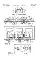
- FIG. 2is a side view partially in section of a heat rejecting mounting for a series of electronic device packages using the spring clips of the invention.
- FIG. 3is a top view thereof.
- FIG. 4is a bottom view thereof.
- FIG. 5is a side view of a first assembly step orienting the spring clip or spring clips with a heatsink.
- FIG. 6is a side view of a subsequent step where a second bend of each spring clip enters an aperture of the heatsink.
- FIG. 7is a side view of a still subsequent step showing the downward force and the compression of the portions of the clip within the aperture.
- FIG. 8is a side view of a final step where a barb(s) of the spring clip latches against an opposite surface of the heatsink to lock the package(s) on a first surface of the heatsink.
- FIG. 2Two embodiments of the invention are seen in FIG. 2 where a single electronic device package 60A is mounted on a heatsink or substrate 50 by a spring clip 20 pressed into an aperture 53A in the heatsink 50 and a pair of electronic device packages 60B and 60C are mounted on the heatsink 50 by a spring clip 40 pressed into a similar aperture 53B in the heatsink 50.
- Each spring clip 20 and 40comprises a continuous spring band with a similar one side including a clamping portion forming an angular integral first spring finger 21 extending inwardly from a first band end 23 which acts to clamp at area 22 against a top surface of package 60A.
- the package 60Aupon clamped assembly, is in abutment with a top flat surface 51 of the heatsink 50 either directly or in one embodiment on an optional, rectangular or other shaped electrical insulator sheet 63, preferably having a high coefficient of heat transfer.
- the insulator sheet 63typically would be a mica sheet or a silicone rubber sheet of about 10 mil thickness.
- a first bend 25 of less than 90°forms a depending substantially linear intermediate first band portion 26 extending at an acute angle ⁇ of from about 40°-80° from spring finger 21 in a pre-insertion mode, preferably at an angle of about 65°, to a second bend 27 of about 180° to then form a second band portion 28 generally parallel to (in operational locking mode) and spaced from the intermediate first band portion 26, together forming an intergral U-shaped member for insertion into a substrate aperture.
- the first bend 25includes a central aperture in the form of a rectangular slot 25a which facilitates bending and leaves a pair of bent integral connecting links between the first spring finger 21 and the intermediate first band portion 26.
- a third bend 29extends outwardly (oppositely relative to spring finger 21) from the second band portion 28 forming a band distal lip 30.
- the bottom portion 31 of the intermediate band portion 26is pushed into aperture 53A until distal lip 30 seats on surface 51 and the end of a spring barb 32 adjacent to the intersection of the intermediate first band portion 26 and the second bend 27 springs outwardly to seat against an opposite under surface 52 of the heatsink 50 immediately adjacent to one edge 51a of two opposed linear edges 51a, 51b of the heatsink aperture 53A (FIG. 4).
- the central barb 32is formed by slits 45, 46 (cut-outs) in portion 31 adjacent to bend 27.
- FIG. 2also illustrates a second embodiment of the invention where the second band portion 28 of the first embodiment is an intermediate second band portion 46 which extends generally parallel to the intermediate first band portion 26 to a third bend 49 also forming an angle ⁇ with a second spring finger 41 which is spring pressed at 42 against a top flat surface of package 60C. Since the illustrated left side of clip 40 is the same as the left side of clip 20, particularly in showing the spring finger 21 clamping package 60B, it is seen that spring clip 40 simultaneously clamps two linearly spaced packages utilizing only one heatsink aperture 53B. In this second embodiment barbs 43 and 44 are formed adjacent to the outer edges of the bend 27 by parallel slits 47, 48 with a central link 55 therebetween bisecting the bend 27.
- the spring finger 41has the same profile and height as spring finger 21 so that two packages 60B and 60C of the same height can be clamped on heatsink 50.
- spring fingers 21 and 41 in a double clipcan be at different heights to accommodate packages of different height.
- a slightly bent tip 39is provided at the ends of the clips for lifting the spring fingers 21 and 41 from the packages, if it is desired to remove a package(s) from the heatsink 50 for analysis or replacement.
- the single spring clip 20 and the double spring clip 40both have a width W 2 closely approaching the width W 1 of a transistor package (not counting the length of leads 19).
- W 1 of the packagewill be about 8 mm and width W 2 of the clip will be about 7 mm.
- the width W 2will be from about 40 to 100% of W 1 .
- the overall longitudinal length of the clips 20 and 40 in their bent formwill be about 17 mm and 26 mm, respectively.
- the heatsink 50is typically made of a 1100-H14 aluminum alloy having a thickness of from about 1 to 2 mm.
- a heat conducting tab 33extends from the typical transistor and diode package (60A-60C) and are spring finger pressed against the heatsink 50 to assist in transferring heat from the package to the heatsink 50.
- the spring clips 20 and 40are made from about 0.3 mm thick SUS 301-3/4H stainless steel.
- the effective clamping range of the spring fingers 21 and 41 as shown in the drawingsis from about 4 to 6.4 mm.
- FIGS. 5-8The assembly of the spring clips 20 and 40 to the heatsink 50 is seen in FIGS. 5-8.
- the spring clips 20 and 40are oriented by suitable automatic fixturing (not shown) or manually, individually or together aligned with respective heatsink apertures 53A and 53B.
- a downward or transverse force (arrows 80, 81)is applied (FIG. 6) to bend 25 and the distal lip 30 (FIG. 2) of the single spring clip 20 and a similar force (arrows 90, 91) applied to bends 25 and 49 (FIG. 2) of the double spring clip 40.
- the spring clips 20 and 40may be forced down directly onto the package(s) 60A (60B and 60C) and into the heatsink apertures 53A and 53B or may be pre-mounted loosely in the heatsink panel. The respective forces push the bends 27 into heatsink apertures 53A and 53B. As the spring clips 20 and 40 are further pushed into the apertures 53A and 53B (FIG. 7) the barb 32 and barbs 43, 44 are compressed and the spring fingers 21 and 21, 41, respectively, slide outwardly on the top surface of the respective packages 60A-60C and clamp the packages 60A-60C against the top surface 51 of the heatsink 50. As seen in FIG.
- the barbs 32 and 43,44spring outwardly to lock adjacent the underside 52 of the heatsink 50 adjacent to the edge 51a of aperture 53A and edges 51a and 51b of aperture 53B, as seen also in FIG. 4.
- the respective packages 60A and 60B, 60Care then firmly clamped and locked onto the top surface 51 of the heatsink 50.
- the double spring clip 40may be used also to mount a single package either under spring finger 21 or spring finger 41.
Landscapes
- Engineering & Computer Science (AREA)
- Microelectronics & Electronic Packaging (AREA)
- Physics & Mathematics (AREA)
- Condensed Matter Physics & Semiconductors (AREA)
- General Physics & Mathematics (AREA)
- Computer Hardware Design (AREA)
- Power Engineering (AREA)
- Cooling Or The Like Of Electrical Apparatus (AREA)
- Cooling Or The Like Of Semiconductors Or Solid State Devices (AREA)
Abstract
Description
Claims (11)
Priority Applications (1)
| Application Number | Priority Date | Filing Date | Title |
|---|---|---|---|
| US08/859,766US5896270A (en) | 1997-05-21 | 1997-05-21 | Heat sink spring clip |
Applications Claiming Priority (1)
| Application Number | Priority Date | Filing Date | Title |
|---|---|---|---|
| US08/859,766US5896270A (en) | 1997-05-21 | 1997-05-21 | Heat sink spring clip |
Publications (1)
| Publication Number | Publication Date |
|---|---|
| US5896270Atrue US5896270A (en) | 1999-04-20 |
Family
ID=25331652
Family Applications (1)
| Application Number | Title | Priority Date | Filing Date |
|---|---|---|---|
| US08/859,766Expired - Fee RelatedUS5896270A (en) | 1997-05-21 | 1997-05-21 | Heat sink spring clip |
Country Status (1)
| Country | Link |
|---|---|
| US (1) | US5896270A (en) |
Cited By (31)
| Publication number | Priority date | Publication date | Assignee | Title |
|---|---|---|---|---|
| US6049459A (en)* | 1997-11-17 | 2000-04-11 | Lucent Technologies, Inc. | Nesting clamps for electrical components |
| US6088226A (en)* | 1999-03-31 | 2000-07-11 | Lucent Technologies, Inc. | Multiple-component clamp and related method for attaching multiple heat-generating components to a heatsink |
| US6266244B1 (en)* | 1999-10-25 | 2001-07-24 | Harman International Industries Incorporated | Mounting method and apparatus for electrical components |
| US6518507B1 (en)* | 2001-07-20 | 2003-02-11 | Hon Hai Precision Ind. Co., Ltd. | Readily attachable heat sink assembly |
| US6639796B2 (en)* | 2002-01-24 | 2003-10-28 | Agilent Technologies, Inc. | Fastenerless clip for quick installation and removal of system components in a computer system |
| US6765798B1 (en) | 2003-06-19 | 2004-07-20 | Curtiss-Wright Controls, Inc. | Electronic thermal management utilizing device with deflectable, two-leg conductive member; and with elastic, thermally-conductive material there between |
| US20040208030A1 (en)* | 2002-01-24 | 2004-10-21 | Bhate Suresh K. | High power density inverter and components thereof |
| US20040260245A1 (en)* | 2003-06-19 | 2004-12-23 | Clem Michael F. | Method for endoscopic, transgastric access into the abdominal cavity |
| US20050013121A1 (en)* | 2003-07-16 | 2005-01-20 | Tsung-Lung Lee | Heat dissipation device including wire clips |
| US20050057907A1 (en)* | 2003-09-12 | 2005-03-17 | Hewlett-Packard Development Company, L.P. | Circuit board assembly |
| US20050073813A1 (en)* | 2003-10-07 | 2005-04-07 | Hewlett-Packard Development Company, L.P. | Circuit board assembly |
| US20050073817A1 (en)* | 2003-10-07 | 2005-04-07 | Hewlett-Packard Development Company, L.P. | Circuit board assembly |
| US20060114659A1 (en)* | 2004-12-01 | 2006-06-01 | Cisco Technology, Inc. | Techniques for attaching a heatsink to a circuit board using anchors which install from an underside of the circuit board |
| US20060114658A1 (en)* | 2004-12-01 | 2006-06-01 | George Sya | Techniques for attaching a heatsink to a circuit board using anchors which install from an underside of the circuit board |
| US7056144B2 (en) | 2004-02-19 | 2006-06-06 | Hewlett-Packard Development Company, L.P. | Offset compensation system |
| US20060232942A1 (en)* | 2005-03-31 | 2006-10-19 | Hitachi Industrial Equipment Systems Co., Ltd | Electric circuit module as well as power converter and vehicle-mounted electric system that include the module |
| US7397666B2 (en) | 2006-10-25 | 2008-07-08 | Hewlett-Packard Development Company, L.P. | Wedge lock |
| US20090168360A1 (en)* | 2008-01-02 | 2009-07-02 | Harman International Industries, Incorporated | Clamp for electrical devices |
| US20090175003A1 (en)* | 2008-01-04 | 2009-07-09 | Apple Inc. | Systems and methods for cooling electronic devices using airflow dividers |
| US7742310B2 (en) | 2006-09-29 | 2010-06-22 | Hewlett-Packard Development Company, L.P. | Sequencer |
| US20110013374A1 (en)* | 2009-07-16 | 2011-01-20 | Kechuan Kevin Liu | Integral Spring Clip for Heat Dissipators |
| AT510195A1 (en)* | 2010-07-28 | 2012-02-15 | Siemens Ag | JIG |
| US20130010428A1 (en)* | 2011-07-08 | 2013-01-10 | Tdk Corporation | Fixing spring and heat sink structure for electronic component |
| US20130083486A1 (en)* | 2011-10-04 | 2013-04-04 | Lsis Co., Ltd. | Springy clip type apparatus for fastening power semiconductor |
| US20130161074A1 (en)* | 2011-12-22 | 2013-06-27 | Hon Hai Precision Industry Co., Ltd. | Electronic device with heat sink |
| US8893770B2 (en) | 2011-07-29 | 2014-11-25 | Schneider Electric It Corporation | Heat sink assembly for electronic components |
| US9312201B2 (en) | 2010-12-30 | 2016-04-12 | Schneider Electric It Corporation | Heat dissipation device |
| US10109936B2 (en)* | 2016-12-26 | 2018-10-23 | Denso Corporation | Electronic device |
| US20190069438A1 (en)* | 2017-08-23 | 2019-02-28 | Delta Electronics (Shanghai) Co., Ltd. | Power module assembly and assembling method thereof |
| US11063495B2 (en)* | 2019-07-01 | 2021-07-13 | Nidec Motor Corporation | Heatsink clamp for multiple electronic components |
| CN113394189A (en)* | 2021-06-11 | 2021-09-14 | 广州市粤创芯科技有限公司 | Integrated circuit packaging structure with double rows of pins and packaging process thereof |
Citations (5)
| Publication number | Priority date | Publication date | Assignee | Title |
|---|---|---|---|---|
| US2825948A (en)* | 1953-01-21 | 1958-03-11 | United Carr Fastener Corp | Sheet metal fastening device |
| US3673643A (en)* | 1969-11-19 | 1972-07-04 | Amp Inc | Heat seal retaining clips |
| US4964198A (en)* | 1988-09-21 | 1990-10-23 | Avvid Engineering, Inc. | V-shaped clip for attaching a semiconductor device to a heat sink |
| US5466970A (en)* | 1992-08-24 | 1995-11-14 | Thermalloy, Inc. | Hooked spring clip |
| US5563450A (en)* | 1995-01-27 | 1996-10-08 | National Semiconductor Corporation | Spring grounding clip for computer peripheral card |
- 1997
- 1997-05-21USUS08/859,766patent/US5896270A/ennot_activeExpired - Fee Related
Patent Citations (5)
| Publication number | Priority date | Publication date | Assignee | Title |
|---|---|---|---|---|
| US2825948A (en)* | 1953-01-21 | 1958-03-11 | United Carr Fastener Corp | Sheet metal fastening device |
| US3673643A (en)* | 1969-11-19 | 1972-07-04 | Amp Inc | Heat seal retaining clips |
| US4964198A (en)* | 1988-09-21 | 1990-10-23 | Avvid Engineering, Inc. | V-shaped clip for attaching a semiconductor device to a heat sink |
| US5466970A (en)* | 1992-08-24 | 1995-11-14 | Thermalloy, Inc. | Hooked spring clip |
| US5563450A (en)* | 1995-01-27 | 1996-10-08 | National Semiconductor Corporation | Spring grounding clip for computer peripheral card |
Cited By (46)
| Publication number | Priority date | Publication date | Assignee | Title |
|---|---|---|---|---|
| US6049459A (en)* | 1997-11-17 | 2000-04-11 | Lucent Technologies, Inc. | Nesting clamps for electrical components |
| US6088226A (en)* | 1999-03-31 | 2000-07-11 | Lucent Technologies, Inc. | Multiple-component clamp and related method for attaching multiple heat-generating components to a heatsink |
| US6266244B1 (en)* | 1999-10-25 | 2001-07-24 | Harman International Industries Incorporated | Mounting method and apparatus for electrical components |
| US6518507B1 (en)* | 2001-07-20 | 2003-02-11 | Hon Hai Precision Ind. Co., Ltd. | Readily attachable heat sink assembly |
| US6980450B2 (en) | 2002-01-24 | 2005-12-27 | Inverters Unlimited, Inc. | High power density inverter and components thereof |
| US20040208030A1 (en)* | 2002-01-24 | 2004-10-21 | Bhate Suresh K. | High power density inverter and components thereof |
| US6639796B2 (en)* | 2002-01-24 | 2003-10-28 | Agilent Technologies, Inc. | Fastenerless clip for quick installation and removal of system components in a computer system |
| US20040260245A1 (en)* | 2003-06-19 | 2004-12-23 | Clem Michael F. | Method for endoscopic, transgastric access into the abdominal cavity |
| US6765798B1 (en) | 2003-06-19 | 2004-07-20 | Curtiss-Wright Controls, Inc. | Electronic thermal management utilizing device with deflectable, two-leg conductive member; and with elastic, thermally-conductive material there between |
| US7233496B2 (en)* | 2003-07-16 | 2007-06-19 | Fu Zhun Precision Ind. (Shenzhen) Co., Ltd. | Heat dissipation device including wire clips |
| US20050013121A1 (en)* | 2003-07-16 | 2005-01-20 | Tsung-Lung Lee | Heat dissipation device including wire clips |
| US20050057907A1 (en)* | 2003-09-12 | 2005-03-17 | Hewlett-Packard Development Company, L.P. | Circuit board assembly |
| US20050073813A1 (en)* | 2003-10-07 | 2005-04-07 | Hewlett-Packard Development Company, L.P. | Circuit board assembly |
| US20050073817A1 (en)* | 2003-10-07 | 2005-04-07 | Hewlett-Packard Development Company, L.P. | Circuit board assembly |
| US7646595B2 (en) | 2003-10-07 | 2010-01-12 | Hewlett-Packard Development Company, L.P. | Computing device |
| US7345891B2 (en) | 2003-10-07 | 2008-03-18 | Hewlett-Packard Development Company, L.P. | Circuit board assembly |
| US7061126B2 (en) | 2003-10-07 | 2006-06-13 | Hewlett-Packard Development Company, L.P. | Circuit board assembly |
| US7056144B2 (en) | 2004-02-19 | 2006-06-06 | Hewlett-Packard Development Company, L.P. | Offset compensation system |
| US7321493B2 (en)* | 2004-12-01 | 2008-01-22 | Cisco Technology, Inc. | Techniques for attaching a heatsink to a circuit board using anchors which install from an underside of the circuit board |
| US7324344B2 (en) | 2004-12-01 | 2008-01-29 | Cisco Technology, Inc. | Techniques for attaching a heatsink to a circuit board using anchors which install from an underside of the circuit board |
| US20060114658A1 (en)* | 2004-12-01 | 2006-06-01 | George Sya | Techniques for attaching a heatsink to a circuit board using anchors which install from an underside of the circuit board |
| US20060114659A1 (en)* | 2004-12-01 | 2006-06-01 | Cisco Technology, Inc. | Techniques for attaching a heatsink to a circuit board using anchors which install from an underside of the circuit board |
| US20060232942A1 (en)* | 2005-03-31 | 2006-10-19 | Hitachi Industrial Equipment Systems Co., Ltd | Electric circuit module as well as power converter and vehicle-mounted electric system that include the module |
| US7745952B2 (en)* | 2005-03-31 | 2010-06-29 | Hitachi Industrial Equipment Systems Co., Ltd. | Electric circuit module with improved heat dissipation characteristics using a fixing tool for fixing an electric apparatus to a heat sink |
| US7742310B2 (en) | 2006-09-29 | 2010-06-22 | Hewlett-Packard Development Company, L.P. | Sequencer |
| US7397666B2 (en) | 2006-10-25 | 2008-07-08 | Hewlett-Packard Development Company, L.P. | Wedge lock |
| US20090168360A1 (en)* | 2008-01-02 | 2009-07-02 | Harman International Industries, Incorporated | Clamp for electrical devices |
| US7746653B2 (en) | 2008-01-02 | 2010-06-29 | Harman International Industries Incorporated | Clamp for electrical devices |
| WO2009088862A3 (en)* | 2008-01-04 | 2010-02-25 | Apple Inc. | Systems and methods for cooling electronic devices using airflow dividers |
| US20090175003A1 (en)* | 2008-01-04 | 2009-07-09 | Apple Inc. | Systems and methods for cooling electronic devices using airflow dividers |
| US7764493B2 (en) | 2008-01-04 | 2010-07-27 | Apple Inc. | Systems and methods for cooling electronic devices using airflow dividers |
| US20110013374A1 (en)* | 2009-07-16 | 2011-01-20 | Kechuan Kevin Liu | Integral Spring Clip for Heat Dissipators |
| AT510195B1 (en)* | 2010-07-28 | 2013-08-15 | Siemens Ag | JIG |
| AT510195A1 (en)* | 2010-07-28 | 2012-02-15 | Siemens Ag | JIG |
| DE102011076879B4 (en)* | 2010-07-28 | 2014-07-31 | Siemens Aktiengesellschaft | Arrangement for pressing an electronic component to a heat sink |
| US9312201B2 (en) | 2010-12-30 | 2016-04-12 | Schneider Electric It Corporation | Heat dissipation device |
| US20130010428A1 (en)* | 2011-07-08 | 2013-01-10 | Tdk Corporation | Fixing spring and heat sink structure for electronic component |
| US8893770B2 (en) | 2011-07-29 | 2014-11-25 | Schneider Electric It Corporation | Heat sink assembly for electronic components |
| US9030825B2 (en)* | 2011-10-04 | 2015-05-12 | Lsis Co., Ltd. | Springy clip type apparatus for fastening power semiconductor |
| US20130083486A1 (en)* | 2011-10-04 | 2013-04-04 | Lsis Co., Ltd. | Springy clip type apparatus for fastening power semiconductor |
| US20130161074A1 (en)* | 2011-12-22 | 2013-06-27 | Hon Hai Precision Industry Co., Ltd. | Electronic device with heat sink |
| US10109936B2 (en)* | 2016-12-26 | 2018-10-23 | Denso Corporation | Electronic device |
| US20190069438A1 (en)* | 2017-08-23 | 2019-02-28 | Delta Electronics (Shanghai) Co., Ltd. | Power module assembly and assembling method thereof |
| US10638646B2 (en)* | 2017-08-23 | 2020-04-28 | Delta Electronics (Shanghai) Co., Ltd. | Power module assembly and assembling method thereof |
| US11063495B2 (en)* | 2019-07-01 | 2021-07-13 | Nidec Motor Corporation | Heatsink clamp for multiple electronic components |
| CN113394189A (en)* | 2021-06-11 | 2021-09-14 | 广州市粤创芯科技有限公司 | Integrated circuit packaging structure with double rows of pins and packaging process thereof |
Similar Documents
| Publication | Publication Date | Title |
|---|---|---|
| US5896270A (en) | Heat sink spring clip | |
| CA1204522A (en) | Heat dissipator for semiconductor devices | |
| US5304735A (en) | Heat sink for an electronic pin grid array | |
| US5331507A (en) | Clip for mounting a heat sink on an electronic device package | |
| US5381041A (en) | Self clamping heat sink | |
| EP0855089B1 (en) | Solderable transistor clip and heat sink | |
| US5759004A (en) | MLT bent leg pushmount | |
| US6582100B1 (en) | LED mounting system | |
| US5581442A (en) | Spring clip for clamping a heat sink module to an electronic module | |
| US5170325A (en) | Spring element for a group of components of an electronic control device | |
| US7672136B2 (en) | Heat sink assembly | |
| US6297961B1 (en) | Semiconductor module and heat sink used in such module | |
| JPS6390199A (en) | Device holding member | |
| US7277288B2 (en) | Heat sink assembly with retention module and clip | |
| US6120000A (en) | Quick mount base for attaching an electrical component to a mounting rail with an edge strip | |
| US20070263363A1 (en) | Fixing apparatus for heat sink | |
| US5068764A (en) | Electronic device package mounting assembly | |
| US20100271784A1 (en) | Heat sink assembly having a clip | |
| US6501656B1 (en) | Clip for heat sink | |
| JPH10504130A (en) | Base mounted halogen bulb without cement | |
| US5869897A (en) | Mounting arrangement for securing an intergrated circuit package to heat sink | |
| US6400572B1 (en) | Fastener for a heat sink | |
| US6188131B1 (en) | Clip for retaining a heatsink onto an electronic component | |
| US20020043359A1 (en) | Heat sink for electronic parts and manufacture thereof | |
| US6029330A (en) | Tool for compressing a torsional spring for clamping a heat sink |
Legal Events
| Date | Code | Title | Description |
|---|---|---|---|
| AS | Assignment | Owner name:COMPUTER PRODUCTS, INC., CALIFORNIA Free format text:ASSIGNMENT OF ASSIGNORS INTEREST;ASSIGNOR:TSUI, JONATHAN H.K.;REEL/FRAME:008572/0676 Effective date:19970505 | |
| AS | Assignment | Owner name:BANK OF AMERICA, N.A., CALIFORNIA Free format text:SECURITY AGREEMENT;ASSIGNORS:ARTESYN TECHNOLOGIES, INC., ARTESYN NORTH AMERICA, INC.;ARTESYN CAYMAN LP, ARTESYN DELAWARE LLC;ARTESYN TECHNOLOGIES COMMUNICATION PRODUCTS, INC.;AND OTHERS;REEL/FRAME:012551/0310 Effective date:20020115 | |
| REMI | Maintenance fee reminder mailed | ||
| AS | Assignment | Owner name:ARTESYN CAYMAN LP, FLORIDA Free format text:RELEASE OF SECURITY INTEREST;ASSIGNOR:BANK OF AMERICA, N.A., AS AGENT;REEL/FRAME:013933/0579 Effective date:20030326 Owner name:ARTESYN COMMUNICATION PRODUCTS, INC., WISCONSIN Free format text:RELEASE OF SECURITY INTEREST;ASSIGNOR:BANK OF AMERICA, N.A., AS AGENT;REEL/FRAME:013933/0579 Effective date:20030326 Owner name:ARTESYN DELAWARE LLC, FLORIDA Free format text:RELEASE OF SECURITY INTEREST;ASSIGNOR:BANK OF AMERICA, N.A., AS AGENT;REEL/FRAME:013933/0579 Effective date:20030326 Owner name:ARTESYN NORTH AMERICA, INC., MINNESOTA Free format text:RELEASE OF SECURITY INTEREST;ASSIGNOR:BANK OF AMERICA, N.A., AS AGENT;REEL/FRAME:013933/0579 Effective date:20030326 Owner name:ARTESYN TECHNOLOGIES, INC., FLORIDA Free format text:RELEASE OF SECURITY INTEREST;ASSIGNOR:BANK OF AMERICA, N.A., AS AGENT;REEL/FRAME:013933/0579 Effective date:20030326 | |
| LAPS | Lapse for failure to pay maintenance fees | ||
| STCH | Information on status: patent discontinuation | Free format text:PATENT EXPIRED DUE TO NONPAYMENT OF MAINTENANCE FEES UNDER 37 CFR 1.362 | |
| FP | Lapsed due to failure to pay maintenance fee | Effective date:20030420 |