US5896190A - Intelligent vehicle highway system sensor and method - Google Patents
Intelligent vehicle highway system sensor and methodDownload PDFInfo
- Publication number
- US5896190A US5896190AUS08/948,228US94822897AUS5896190AUS 5896190 AUS5896190 AUS 5896190AUS 94822897 AUS94822897 AUS 94822897AUS 5896190 AUS5896190 AUS 5896190A
- Authority
- US
- United States
- Prior art keywords
- vehicle
- roadway
- laser
- sensor
- receiving
- Prior art date
- Legal status (The legal status is an assumption and is not a legal conclusion. Google has not performed a legal analysis and makes no representation as to the accuracy of the status listed.)
- Expired - Lifetime
Links
- 238000000034methodMethods0.000titleclaimsdescription48
- 238000001514detection methodMethods0.000claimsabstractdescription15
- 230000005855radiationEffects0.000claimsdescription34
- 230000001427coherent effectEffects0.000claimsdescription28
- 238000012545processingMethods0.000claimsdescription21
- 230000000977initiatory effectEffects0.000claimsdescription11
- 238000012937correctionMethods0.000claimsdescription10
- 230000008859changeEffects0.000claimsdescription8
- 238000012986modificationMethods0.000claimsdescription3
- 230000004048modificationEffects0.000claimsdescription3
- 230000036962time dependentEffects0.000claims19
- 238000005259measurementMethods0.000abstractdescription36
- 238000005516engineering processMethods0.000abstractdescription4
- 238000003384imaging methodMethods0.000abstractdescription3
- 239000007921spraySubstances0.000description20
- 230000003287optical effectEffects0.000description16
- 238000010586diagramMethods0.000description11
- 238000004364calculation methodMethods0.000description8
- 230000008569processEffects0.000description7
- 238000000926separation methodMethods0.000description7
- 238000005507sprayingMethods0.000description7
- 239000000463materialSubstances0.000description5
- 239000003990capacitorSubstances0.000description4
- XUIMIQQOPSSXEZ-UHFFFAOYSA-NSiliconChemical compound[Si]XUIMIQQOPSSXEZ-UHFFFAOYSA-N0.000description3
- 230000001976improved effectEffects0.000description3
- 229910052710siliconInorganic materials0.000description3
- 239000010703siliconSubstances0.000description3
- 241000207199CitrusSpecies0.000description2
- 229910000530Gallium indium arsenideInorganic materials0.000description2
- 230000003213activating effectEffects0.000description2
- 229910052782aluminiumInorganic materials0.000description2
- XAGFODPZIPBFFR-UHFFFAOYSA-NaluminiumChemical compound[Al]XAGFODPZIPBFFR-UHFFFAOYSA-N0.000description2
- 238000004458analytical methodMethods0.000description2
- 235000020971citrus fruitsNutrition0.000description2
- 230000007423decreaseEffects0.000description2
- 230000009977dual effectEffects0.000description2
- 239000000835fiberSubstances0.000description2
- 238000002347injectionMethods0.000description2
- 239000007924injectionSubstances0.000description2
- 238000000691measurement methodMethods0.000description2
- 239000013307optical fiberSubstances0.000description2
- 239000007787solidSubstances0.000description2
- 230000001960triggered effectEffects0.000description2
- 241001465589Antigastra catalaunalisSpecies0.000description1
- KXNLCSXBJCPWGL-UHFFFAOYSA-N[Ga].[As].[In]Chemical compound[Ga].[As].[In]KXNLCSXBJCPWGL-UHFFFAOYSA-N0.000description1
- 230000003466anti-cipated effectEffects0.000description1
- 230000008901benefitEffects0.000description1
- 230000005540biological transmissionEffects0.000description1
- 238000013480data collectionMethods0.000description1
- 230000007123defenseEffects0.000description1
- 230000001419dependent effectEffects0.000description1
- 238000011161developmentMethods0.000description1
- 230000000694effectsEffects0.000description1
- 230000007613environmental effectEffects0.000description1
- 230000004907fluxEffects0.000description1
- 238000009499grossingMethods0.000description1
- 239000004009herbicideSubstances0.000description1
- 239000003562lightweight materialSubstances0.000description1
- 230000007257malfunctionEffects0.000description1
- 238000004519manufacturing processMethods0.000description1
- 229910052751metalInorganic materials0.000description1
- 239000002184metalSubstances0.000description1
- 230000000116mitigating effectEffects0.000description1
- 239000000203mixtureSubstances0.000description1
- 230000009467reductionEffects0.000description1
- 230000008685targetingEffects0.000description1
- 238000012360testing methodMethods0.000description1
- 230000009466transformationEffects0.000description1
- 238000002834transmittanceMethods0.000description1
Images


Classifications
- G—PHYSICS
- G08—SIGNALLING
- G08G—TRAFFIC CONTROL SYSTEMS
- G08G1/00—Traffic control systems for road vehicles
- G08G1/01—Detecting movement of traffic to be counted or controlled
- G08G1/04—Detecting movement of traffic to be counted or controlled using optical or ultrasonic detectors
- A—HUMAN NECESSITIES
- A01—AGRICULTURE; FORESTRY; ANIMAL HUSBANDRY; HUNTING; TRAPPING; FISHING
- A01M—CATCHING, TRAPPING OR SCARING OF ANIMALS; APPARATUS FOR THE DESTRUCTION OF NOXIOUS ANIMALS OR NOXIOUS PLANTS
- A01M7/00—Special adaptations or arrangements of liquid-spraying apparatus for purposes covered by this subclass
- A01M7/0089—Regulating or controlling systems
- G—PHYSICS
- G01—MEASURING; TESTING
- G01S—RADIO DIRECTION-FINDING; RADIO NAVIGATION; DETERMINING DISTANCE OR VELOCITY BY USE OF RADIO WAVES; LOCATING OR PRESENCE-DETECTING BY USE OF THE REFLECTION OR RERADIATION OF RADIO WAVES; ANALOGOUS ARRANGEMENTS USING OTHER WAVES
- G01S17/00—Systems using the reflection or reradiation of electromagnetic waves other than radio waves, e.g. lidar systems
- G01S17/02—Systems using the reflection of electromagnetic waves other than radio waves
- G01S17/04—Systems determining the presence of a target
- G—PHYSICS
- G01—MEASURING; TESTING
- G01S—RADIO DIRECTION-FINDING; RADIO NAVIGATION; DETERMINING DISTANCE OR VELOCITY BY USE OF RADIO WAVES; LOCATING OR PRESENCE-DETECTING BY USE OF THE REFLECTION OR RERADIATION OF RADIO WAVES; ANALOGOUS ARRANGEMENTS USING OTHER WAVES
- G01S17/00—Systems using the reflection or reradiation of electromagnetic waves other than radio waves, e.g. lidar systems
- G01S17/02—Systems using the reflection of electromagnetic waves other than radio waves
- G01S17/06—Systems determining position data of a target
- G01S17/08—Systems determining position data of a target for measuring distance only
- G01S17/10—Systems determining position data of a target for measuring distance only using transmission of interrupted, pulse-modulated waves
- G01S17/14—Systems determining position data of a target for measuring distance only using transmission of interrupted, pulse-modulated waves wherein a voltage or current pulse is initiated and terminated in accordance with the pulse transmission and echo reception respectively, e.g. using counters
- G—PHYSICS
- G01—MEASURING; TESTING
- G01S—RADIO DIRECTION-FINDING; RADIO NAVIGATION; DETERMINING DISTANCE OR VELOCITY BY USE OF RADIO WAVES; LOCATING OR PRESENCE-DETECTING BY USE OF THE REFLECTION OR RERADIATION OF RADIO WAVES; ANALOGOUS ARRANGEMENTS USING OTHER WAVES
- G01S17/00—Systems using the reflection or reradiation of electromagnetic waves other than radio waves, e.g. lidar systems
- G01S17/02—Systems using the reflection of electromagnetic waves other than radio waves
- G01S17/06—Systems determining position data of a target
- G01S17/08—Systems determining position data of a target for measuring distance only
- G01S17/10—Systems determining position data of a target for measuring distance only using transmission of interrupted, pulse-modulated waves
- G01S17/18—Systems determining position data of a target for measuring distance only using transmission of interrupted, pulse-modulated waves wherein range gates are used
- G—PHYSICS
- G01—MEASURING; TESTING
- G01S—RADIO DIRECTION-FINDING; RADIO NAVIGATION; DETERMINING DISTANCE OR VELOCITY BY USE OF RADIO WAVES; LOCATING OR PRESENCE-DETECTING BY USE OF THE REFLECTION OR RERADIATION OF RADIO WAVES; ANALOGOUS ARRANGEMENTS USING OTHER WAVES
- G01S17/00—Systems using the reflection or reradiation of electromagnetic waves other than radio waves, e.g. lidar systems
- G01S17/02—Systems using the reflection of electromagnetic waves other than radio waves
- G01S17/06—Systems determining position data of a target
- G01S17/42—Simultaneous measurement of distance and other co-ordinates
- G—PHYSICS
- G01—MEASURING; TESTING
- G01S—RADIO DIRECTION-FINDING; RADIO NAVIGATION; DETERMINING DISTANCE OR VELOCITY BY USE OF RADIO WAVES; LOCATING OR PRESENCE-DETECTING BY USE OF THE REFLECTION OR RERADIATION OF RADIO WAVES; ANALOGOUS ARRANGEMENTS USING OTHER WAVES
- G01S17/00—Systems using the reflection or reradiation of electromagnetic waves other than radio waves, e.g. lidar systems
- G01S17/02—Systems using the reflection of electromagnetic waves other than radio waves
- G01S17/50—Systems of measurement based on relative movement of target
- G01S17/58—Velocity or trajectory determination systems; Sense-of-movement determination systems
- G—PHYSICS
- G01—MEASURING; TESTING
- G01S—RADIO DIRECTION-FINDING; RADIO NAVIGATION; DETERMINING DISTANCE OR VELOCITY BY USE OF RADIO WAVES; LOCATING OR PRESENCE-DETECTING BY USE OF THE REFLECTION OR RERADIATION OF RADIO WAVES; ANALOGOUS ARRANGEMENTS USING OTHER WAVES
- G01S17/00—Systems using the reflection or reradiation of electromagnetic waves other than radio waves, e.g. lidar systems
- G01S17/88—Lidar systems specially adapted for specific applications
- G01S17/89—Lidar systems specially adapted for specific applications for mapping or imaging
- G—PHYSICS
- G01—MEASURING; TESTING
- G01S—RADIO DIRECTION-FINDING; RADIO NAVIGATION; DETERMINING DISTANCE OR VELOCITY BY USE OF RADIO WAVES; LOCATING OR PRESENCE-DETECTING BY USE OF THE REFLECTION OR RERADIATION OF RADIO WAVES; ANALOGOUS ARRANGEMENTS USING OTHER WAVES
- G01S7/00—Details of systems according to groups G01S13/00, G01S15/00, G01S17/00
- G01S7/48—Details of systems according to groups G01S13/00, G01S15/00, G01S17/00 of systems according to group G01S17/00
- G01S7/4802—Details of systems according to groups G01S13/00, G01S15/00, G01S17/00 of systems according to group G01S17/00 using analysis of echo signal for target characterisation; Target signature; Target cross-section
- G—PHYSICS
- G01—MEASURING; TESTING
- G01S—RADIO DIRECTION-FINDING; RADIO NAVIGATION; DETERMINING DISTANCE OR VELOCITY BY USE OF RADIO WAVES; LOCATING OR PRESENCE-DETECTING BY USE OF THE REFLECTION OR RERADIATION OF RADIO WAVES; ANALOGOUS ARRANGEMENTS USING OTHER WAVES
- G01S7/00—Details of systems according to groups G01S13/00, G01S15/00, G01S17/00
- G01S7/48—Details of systems according to groups G01S13/00, G01S15/00, G01S17/00 of systems according to group G01S17/00
- G01S7/481—Constructional features, e.g. arrangements of optical elements
- G01S7/4817—Constructional features, e.g. arrangements of optical elements relating to scanning
- G—PHYSICS
- G01—MEASURING; TESTING
- G01S—RADIO DIRECTION-FINDING; RADIO NAVIGATION; DETERMINING DISTANCE OR VELOCITY BY USE OF RADIO WAVES; LOCATING OR PRESENCE-DETECTING BY USE OF THE REFLECTION OR RERADIATION OF RADIO WAVES; ANALOGOUS ARRANGEMENTS USING OTHER WAVES
- G01S7/00—Details of systems according to groups G01S13/00, G01S15/00, G01S17/00
- G01S7/48—Details of systems according to groups G01S13/00, G01S15/00, G01S17/00 of systems according to group G01S17/00
- G01S7/483—Details of pulse systems
- G01S7/486—Receivers
- G—PHYSICS
- G01—MEASURING; TESTING
- G01S—RADIO DIRECTION-FINDING; RADIO NAVIGATION; DETERMINING DISTANCE OR VELOCITY BY USE OF RADIO WAVES; LOCATING OR PRESENCE-DETECTING BY USE OF THE REFLECTION OR RERADIATION OF RADIO WAVES; ANALOGOUS ARRANGEMENTS USING OTHER WAVES
- G01S7/00—Details of systems according to groups G01S13/00, G01S15/00, G01S17/00
- G01S7/48—Details of systems according to groups G01S13/00, G01S15/00, G01S17/00 of systems according to group G01S17/00
- G01S7/481—Constructional features, e.g. arrangements of optical elements
- G01S7/4811—Constructional features, e.g. arrangements of optical elements common to transmitter and receiver
- G01S7/4813—Housing arrangements
- G—PHYSICS
- G01—MEASURING; TESTING
- G01S—RADIO DIRECTION-FINDING; RADIO NAVIGATION; DETERMINING DISTANCE OR VELOCITY BY USE OF RADIO WAVES; LOCATING OR PRESENCE-DETECTING BY USE OF THE REFLECTION OR RERADIATION OF RADIO WAVES; ANALOGOUS ARRANGEMENTS USING OTHER WAVES
- G01S7/00—Details of systems according to groups G01S13/00, G01S15/00, G01S17/00
- G01S7/48—Details of systems according to groups G01S13/00, G01S15/00, G01S17/00 of systems according to group G01S17/00
- G01S7/483—Details of pulse systems
- G01S7/484—Transmitters
- G—PHYSICS
- G01—MEASURING; TESTING
- G01S—RADIO DIRECTION-FINDING; RADIO NAVIGATION; DETERMINING DISTANCE OR VELOCITY BY USE OF RADIO WAVES; LOCATING OR PRESENCE-DETECTING BY USE OF THE REFLECTION OR RERADIATION OF RADIO WAVES; ANALOGOUS ARRANGEMENTS USING OTHER WAVES
- G01S7/00—Details of systems according to groups G01S13/00, G01S15/00, G01S17/00
- G01S7/48—Details of systems according to groups G01S13/00, G01S15/00, G01S17/00 of systems according to group G01S17/00
- G01S7/483—Details of pulse systems
- G01S7/486—Receivers
- G01S7/487—Extracting wanted echo signals, e.g. pulse detection
- G—PHYSICS
- G01—MEASURING; TESTING
- G01S—RADIO DIRECTION-FINDING; RADIO NAVIGATION; DETERMINING DISTANCE OR VELOCITY BY USE OF RADIO WAVES; LOCATING OR PRESENCE-DETECTING BY USE OF THE REFLECTION OR RERADIATION OF RADIO WAVES; ANALOGOUS ARRANGEMENTS USING OTHER WAVES
- G01S7/00—Details of systems according to groups G01S13/00, G01S15/00, G01S17/00
- G01S7/48—Details of systems according to groups G01S13/00, G01S15/00, G01S17/00 of systems according to group G01S17/00
- G01S7/497—Means for monitoring or calibrating
Definitions
- the present inventionrelates generally to object sensors and related methods, and in particular relates to electronic object sensors and methods useful in detecting vehicle speed and shape for classification and input to Intelligent Vehicle Highway Systems (IVHS).
- IVHSIntelligent Vehicle Highway Systems
- a vehicle sensorproviding the presence of a vehicle in a traffic lane and indicating the vehicle speed as it passed the sensor is disclosed in copending Application Ser. No. 07/980,273 referenced above.
- a time-of-flight laser rangefinder conceptis used which measures the normal distance to a highway from a fixed point above the road surface and then measures the distance to any vehicle which either passes or stops under the sensor.
- the conceptteaches the use of two laser beams pulsing at a high rate projected across the road surface at a fixed angle between them. Because of the high repetition rate, the system is also able to determine vehicle speed with an accuracy within one mph and using this calculated speed, develop a longitudinal profile of the vehicle using consecutive range measurements as the vehicle moves under the sensor.
- the principal goals of the inventionare to provide active near-field object sensors which are relatively low in cost, are accurate and have utility in a wide variety of applications.
- the inventioncontemplated a sensor for detecting the presence of an object within an area located in a close range to the sensor, and includes a range finder having means for emitting a directional output of pulsed energy toward the fixed area.
- the emitting meanscomprises a laser diode capable of emitting pulses of coherent infrared radiation, which are used together with collimating optics and a beam splitter to provide two diverging output beams directed toward the near-field area under observation.
- the sensoralso includes means for receiving a portion of the energy reflected from either the area, or an object located within the area.
- the returned pulse energyis then provided as an input to a receiver for determining a time of flight change for pulses between the emitting and receiving means, which may be caused by the presence of an object within the area.
- the sensoris also provided with various features useful in providing outputs which indicate either the speed, census, size or shape of one or more objects in the area.
- the sensoris provided with means for receiving an input from the time of flight determining means and for providing an output indicating whether the object meets one of a plurality of classification criteria (e.g., is the object an automobile, truck or motorcycle).
- the receiving meansincludes two detectors, with means for alternately selecting between the outputs of the two detectors for providing inputs to the time of flight determining means; means are also provided for measuring the time interval between interceptions of the two diverging outputs by a given object, so as to calculate the speed of the object passing through the area.
- Copending application Ser. No. 07/997,737 referenced abovediscloses the generation of three dimensional images of objects by rotating or scanning a laser beam rangefinder, operating at a high pulse rate, in a plane where there is relative motion between the rangefinder and the object to be sensed or imaged in a direction perpendicular to the laser beam plane of rotation.
- This operationcauses the laser rangefinder rotating beam, when passing to a side of the object, to cover the object to be sensed with rangefinder pulses, and thereby, obtain a three dimensional image of the object.
- a preferred embodiment of the three dimensional object sensor taught in the copending applicationtaught the sensing of trees formed in a row for purposes of spraying, counting or measuring the size of the trees.
- the sensoris moved along the ground traveling between rows of trees, crops or foliage with the laser rangefinder scanning on either side of the moving vehicle carrying the sensor in a plane perpendicular to the motion of the vehicle.
- the sensordetects the presence of foliage, it provides a signal activating a spraying system for the efficient spraying of the tree or object being sensed. This operation ensures that spraying takes place only when there is foliage present to intercept the sprayed materials. Economic and environmental benefit is thus realized.
- the agricultural sprayeremploys a pulsed time-of-flight range measuring system having separate apertures for the laser transmitter and receiver.
- the laser beam and receiver field-of-vieware continuously scanned, by a rotating mirror, in a vertical plane which is perpendicular to the forward motion axis of the sprayer vehicle.
- the position of the mirror, and correspondingly the laser beamis determined by means of a shaft encoder attached to the mirror drive motor shaft.
- a single sensormakes range measurements on both sides of the sprayer vehicle as the vehicle moves the sensor between rows of trees. Since the sensor only need to detect the presence of trees, range measurements are only made within elevation angles of plus and minus 45 degrees on each side of the sensor. Data is collected within 180 degrees out of the 360 degrees of a revolution or circular scan.
- the scan traceadvances on consecutive revolutions of the mirror.
- the sensoremploying a distance traveled input from the vehicle, the sensor creates a panorama of images.
- An algorithmdetermines whether trees are present from the measured range data as a function angle.
- Spray unitsare grouped in zones and the sensor provides foliage images for the zones and thus an indication of the amount of spray necessary for a particular tree zone.
- near-field sensorshave also been utilized as intruder alarms and as automatic door operators. Examples of such arrangements are disclosed in the following U.S. Pat. Nos. 3,605,082 to Matthews; 3,644;917 to Perlman; 3,719,938 to Perlman; 3,852,592 to Scoville et al; 3,972,021 to Leitz et al; and 4,433,328 to Saphir et al.
- U.S. Pat. No. 4,768,713discloses the use of an ultrasonic sonar-type sensor to detect the presence of tree foliage, as do U.S. Pat. No. 4,823,268 and U.S. Pat. No. 5,172,861.
- Optical dimensioning techniqueshave been incorporated in industrial uses as disclosed in U.S. Pat. No. 4,179,216 and U.S. Pat. No. 4,490,038.
- the object sensorswere developed by the inventors as an outgrowth of several laser systems developed for Department of Defense and Department of Transportation programs.
- Typically military use of laser optics and electronicsare found in missile systems and target recognition systems.
- Target imagesare produced and are seen as a missile or carrier flies over a targeting area.
- a missilemay be equipped with a laser range finder scanning in a plane perpendicular to the flight path.
- a laser sensor for detecting vehicles and providing outputs useful in determining a three dimensional shape and speed of the vehiclecomprises laser means for determining a range from the sensor to portions of a vehicle wherein the vehicle travels within a sensing zone of the sensor and for providing respective range data outputs corresponding with a sensor angle for each range data output.
- Means for scanning the beams across the vehicleis provided, the scanning means providing means for determining the beam orientation and a corresponding sensor angle.
- meansis provided for determining a distance traveled by the vehicle between locations within the zone. The travel distance provides data representing a distance traveled by each point on the vehicle.
- Meansis also provided for processing the respective range, angle and travel distance data for determining the speed and three dimensional shape of the vehicle.
- the processing meansprovides vehicle classification useful in intelligent vehicle highway systems.
- the sensorin a preferred embodiment comprises a forward and a backward beam emitted by the laser means.
- the forward and backward beamsare separated by a predetermined angle and are emitted toward a fixed area through which the vehicle travels.
- a time signal representative of a travel time for a point on the vehicle to travel between the beamsis determined from time-of-flight data provided by the range data processing means.
- a single transmitter and receiver pairis used in a preferred embodiment of the present invention.
- a sensorfurther comprises two transmitters for emitting a pair of laser beams, means for directing the beams toward zones on a roadway traveled on by the vehicle, and two receivers for converting reflected laser beams from the vehicle to signal voltages, the signal voltages representative of ranges between the receivers and defined points on the vehicle.
- Scanningis provided using an optically reflective surface intercepting the beams and reflecting the beams at predetermined angles from a perpendicular to the roadway.
- the beams reflected off of the vehicleare directed back toward the mirror into corresponding apertures of the receivers.
- Meansare provided for rotatably moving the reflective surface across a reflective angle sufficient for reflecting the beams across a transverse portion of the vehicle, and signal means representative of the sensor angle within the beam plane are also provided.
- the angle signalsare delivered to the processing means for providing range data at corresponding angles and the range and angle data in combination provide a transverse profile of the vehicle.
- the scanningis provide using a mirror intercepting the beams emitted from the transmitter and reflecting the beams onto scanning planes.
- the planesare set at opposing angles from a perpendicular to the roadway.
- the reflected beams directed back toward the mirroris directed into corresponding apertures of the receiver.
- a motor having a rotatable shaftis affixed to the mirror for continuously rotating the mirror about the axis, and an encoder is affixed to the motor shaft for identifying an angular position of the mirror relative to a reference angle.
- the processing meanscomprises a microprocessor programmed to receive respective range and sensor angle data for storing and processing the data for a scanned cycle associated with a timing signal.
- the processed dataresults in a three dimensional shape profile for the vehicle.
- the inventioncomprises an algorithm for comparing the vehicle shape profile with a multiplicity of predetermined vehicle shapes for classifying the vehicle.
- An algorithm of the present inventiontakes the three dimensional vehicle profile and compares it to known vehicle profiles for categorizing the vehicle into classes for use in automatic toll collecting, highway usage data compilation, ferry boat loading direction and the multiplicity of uses needed in the Intelligent Vehicle Highway Systems.
- AVCAutomated Vehicle Classification
- ETMElectronic Toll and Traffic Management
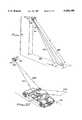
- FIG. 1is a partial perspective view illustrating the operation of the sensor in the preferred embodiment including forward and backward scanned laser beams for intercepting a vehicle as it passes through the beams;
- FIG. 2is a schematic diagram of the object sensor used in the copending application illustrating functional flow relationship of the sensor elements on the copending invention used in an agricultural sprayer;
- FIG. 2Ais a schematic diagram of the laser transmitter illustrating the relationship between the laser device and the lens/prism system
- FIG. 2Bis a schematic diagram of the optical receiver illustrating the relationship of the receiving objective lens and the photodiode converting the optical signal to current pulses which are then converted to a voltage signal using a conventional transimpedance amplifier;
- FIG. 2Cis a schematic diagram of the time to amplitude circuitry used in the preferred embodiments of the inventions of the copending applications;
- FIG. 3is a partial aerial view illustrating various positions of the agricultural sprayer of the copending application traveling between rows of target trees;
- FIG. 4illustrates the laser beam scanning of an exemplary set of identified zones used in the application of herbicides to citrus trees in a typical citrus grove
- FIG. 5is a partial rear view of an air-blast type agricultural sprayer illustrating the selective application of spray materials from selected nozzles to target trees;
- FIG. 6illustrates the relationship between zones and tree size for a particular measurement location
- FIG. 7illustrates a circular queue data structure for a plurality of zones used in storing scanned range data
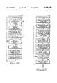
- FIG. 8is a sensor top level flow chart of the copending microprocessor software illustrating the steps from initializing to initiating spray application signals
- FIGS. 9 and 10are perspective views illustrating the operation of the active near-field object sensor in the copending application.
- FIG. 11is a block diagram illustrating the electronic and optics portions of the hardware used with the sensor of the copending invention referred to in FIGS. 9 and 10 above;
- FIG. 12illustrates scan geometry of the present invention for providing high accuracy laser radar with a three inch range resolution for a sensor mounted above a passing vehicle;
- FIG. 13is a perspective view illustrating a three dimensional vehicle profile provided by the present invention.
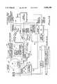
- FIG. 14is a block diagram illustrating the electronic and optics portion of the hardware used with the IVHS sensor of the present invention.
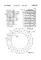
- FIGS. 15A1 and 15A2illustrate functional representations of a multi faceted mirror used in one embodiment of the present invention wherein the rotating mirror has facets of alternating inclination for reflecting an incident beam into a forward beam and a backward beam;
- FIG. 15Bis a perspective view of the multi faceted mirror of FIG. 15A;
- FIG. 16illustrates the forward scanning laser beam and backward scanning laser beam geometry used in the preferred embodiment of the invention
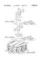
- FIG. 17illustrates the use of a rotating twelve sided polygon mirror to scan a beam and a dual-position nodding mirror deflecting the beam onto alternate rotating mirror facets to reflect the beam into forward and backward scanned beams;
- FIG. 18is a schematic diagram of an embodiment of the present invention using two transmitters and two receivers for forming the forward and backward scanned beams;
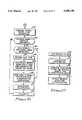
- FIG. 19A and 19Bare block diagrams illustrating the functional flow of the microcontroller and microprocessor, respectively, for the present invention.
- FIGS. 20a through 20jillustrate "American Truck Association Truck Types" by way of example, for use in toll road vehicle data collection and classification;
- FIG. 21is a perspective view illustrating a three dimensional truck profile provided by the present invention illustrated with a black and white ink tracing of a monitor screen;
- FIGS. 22 through 28are interrelated flow charts illustrating a preferred embodiment of the software useful with the present invention.
- a sensoris affixed above a highway 12 for sensing a vehicle 14 passing below the sensor 10.
- FIG. 1illustrates a forward scanned beam 16 intercepting the vehicle 14 as the vehicle 14 begins to pass through an area 18 below the sensor 10 and a backward scanned beam 20 intercepting the vehicle 14a as the vehicle 14a leaves the sensor area 18.
- the inventionconcerns both the method and apparatus used to sense vehicles 14 for determining a vehicle speed and vehicle classification.
- the sensor 510 as illustrated in FIG. 2employs a pulsed time-of-flight range measuring system.
- a laser transmitter 520 and optical receiver 522 having separate apertures 524 and 526 respectivelyare placed side-by-side as illustrated in FIG. 2.
- the transmitted laser beam 528 and receiver 522 field-of-vieware continuously scanned by a rotating mirror 530 in a vertical plane 532 which is perpendicular to a travel axis 534 of a sprayer 512 upon which the sensor 510 is affixed as illustrated in FIG. 3.
- FIG. 3illustrates this by showing a partial aerial view of a sprayer 512 at a first location 512A and a second location 512B between the rows 542.
- the laser transmitter 520 lens system and circuitryemploys a diode laser 519 as an optical source.
- a diode laser 519configured in a pulsed circuit is used to emit 13 nanosecond pulses having a peak radiant flux of approximately thirty watts at 0.91 microns.
- the diode laser 519is driven with fifty amp current pulses generated by an avalanche-transistor pulser well known in the art.
- the 381 micron laser 519 diode junctionemits radiation into a 10 by 40 solid angle.
- a fast focal length (f:0.91) multi element lens 521 having an effective focal length of, for example, on the order of 8.8 millimetersis used to collimate the diode laser emission, resulting in a beam divergence of 46.6 miliradians parallel to the diode junction and 0.12 miliradians perpendicular to the diode junction.
- the collimated laser beamis expanded by a factor of six in the direction parallel to the diode junction using an anamorphic prism 523 pair resulting in a 7.8 miliradians parallel and 0.12 miliradians beam divergence for the laser beam 528 emitted through the aperture 524.
- the optical receiver 522utilizes a lens system and circuitry comprising an objective lens 529 and a silicon PIN photodiode 527 receiving the laser beam 544 at its aperture 526 after it has been reflected from the target tree 514.
- a conventional transimpedance amplifier 525converts the photodiode current pulses to voltage pulses.
- Optical return radiation representing the reflected laser beam 544 incident upon the objective lens 529is focused onto the receiver 522 photodiode 527.
- the receiver field-of-viewis given by the ratio of the photodiode 527 diameter to the receiver lens 529 focal length and, by way of example, may be on the order of 13 miliradians. This value is sufficiently large to facilitate bore sighting the receiver 522 to the 7.8 miliradians transmitter beam width.
- the shaft encoder 536 used in the copending preferred embodimentpulses the laser 519 at a preselected pulse rate, for example, on the order of 2,048 pulses per revolution. This results in range measurements being made at every 3.06 miliradians about the axis 538 of the mirror rotation.
- the laser pulse repetition rateis at 81.92 thousand cycles per second (kHz).
- an on-board styled microprocessor 550is employed that limits the repetition rate to 15 kHz based on the microprocessor cycle time.
- the shaft encoder 536delivers pulses at a rate of 512 pulses per revolution at an angular rotation rate of 29.29 rps.
- the microprocessor 550controls the triggering of the laser transmitter 520 by sending pulse trigger signals 552 which are selected to limit the laser 520 operation to quadrants of rotation on the left and right sides of the sprayer 512 corresponding to tree height, a left scan quadrant 554 and a right scan quadrant 556 as illustrated in FIG. 4.
- the laser transmitter 520is triggered 128 times in each of the preselected tree-occupied quadrants 554 and 556.
- the sensor 510determines a range 540 by measuring the time for one emitted pulse as it leaves the laser transmitter 520 and returns to be detected by the optical receiver 522. This round trip time is divided by two to obtain the time to travel to the target tree 514 and multiplied by the speed of light, the speed of the laser beam 528. An accurate measure of the range 540 is required and thus an accurate measurement of the time is needed.
- the sensor system 510 of FIG. 2includes a range measurement circuit 558 comprising a range gate 557 and an analog time-to-amplitude converter circuit (TAC) 559 as detailed in FIG. 2C.
- TACtime-to-amplitude converter circuit
- This range measurement circuit 558is optically coupled to the laser 519 as means for initiating a start pulse for the range gate.
- a stop pulse for the range measurement circuit 558is provided by a threshold detector contained within the receiver 522.
- the analog techniquewas chosen in the copending invention because of its resolution, smaller size, simpler circuitry, lower power consumption and lower costs when compared with the digital technique.
- the analog range measurement technique specifically used in the present inventionis known as a "time-to-amplitude converter" and has an accuracy of about one percent of measured range and a resolution of about plus or minus five centimeters.
- the specific forms of the range gate 557 and TAC 559are shown and use a constant current source including transistor Q1 to charge a ramp capacitor C38 to obtain a linear voltage ramp whose instantaneous value is a measure of elapsed time.
- the TAC 559 circuitis designed so that the voltage across the capacitor C38 begins ramping down from the positive power supply when the laser 519 fires. The ramp is stopped when either a reflected pulse is received by the receiver 522 or at the end of a measured period of time. A maximum range and thus a maximum measured time period is preselected as an initial value.
- the output of the TAC 559is then converted to a digital format by a ten bit analog-to-digital converter within the microprocessor 550.
- the start timing pulse for the TAC 558is generated by the shaft encoder 536 with a simultaneous pulse 552 causing the laser transmitter 520 to fire.
- the microprocessor 550is programmed to perform three primary tasks which include sensing and calculating tree foliage height 562, activating spray zones 560, and running sensor system diagnostics. To calculate the height 562 of a target tree 514, the range 540 to the tree 514, an angle 564 associated with that range 540, and the height 566 that the sensor is mounted above the ground 568.
- the microprocessor 550provides various outputs to light emitting diodes, presence relays for indicating the presence of an object such as foliage, an RS232 computer interface and relays within the power supply.
- the microprocessor 550receives inputs in addition to those described that include temperature and real time clock pulses. Backup power and circuitry is also included. Such input/output microprocessor information and backup circuitry is well known in the art.
- the range 570 to the top of the tree 514is defined as the last valid range received.
- the range 572 to the bottom of the treeis defined as the first valid range which produces a height above a minimum height threshold 574.
- the range 570 to the top of the tree 514is defined as the first valid range received and the range 572 to the bottom of the tree 514 is defined as the last valid range which produces a height above a minimum height threshold 574.
- a valid rangeis any range 540 less than a predetermined maximum range. Each range 540 reading has a relative angle signal 563 associated with it with respect to the horizontal axis 576 for the copending preferred embodiment.
- This angle signal 563is determined by a counter 565 that is incremented each time the shaft encoder 536 moves one cycle.
- the shaft encoderhas 512 cycles per revolution. Therefore, one tick on the counter translates to an angle 564 of approximately 0.7 degrees and provides an angle signal 563 to the microprocessor 550.
- the height to the top 562 or bottom 572 of the target tree 514can be calculated by multiplying the range 540 measured at a given angle 564 by the sine of that angle 564 and adding the height of the sensor 566 to that product.
- Range 540is defined to be less than a predetermined maximum range and the angle 564 takes on predetermined values between -45 degrees and +45 degrees.
- the agricultural sprayer 512comprises spray heads 518 in the form of controllable nozzles in the preferred embodiment.
- the heads 518are aimed and grouped into zones 560 according to the particular task the sprayer 512. In the embodiment presently in use in a typical Florida orange grove, five zones are used with the top of the highest zone at approximately seventeen feet. The number of zones 560 and the size will vary based on the specific target crop or task.
- the appropriate zonesare identified and the corresponding spray heads 518 are turned on. All appropriate zones 560 as illustrated in FIG. 4 between the bottom 574 and the top 562 of the target tree 514 will be turned on. As illustrated in FIGS. 4 and 5, only those zones 560 appropriate for a given target tree 514 are turned on for applying the spray materials.
- FIG. 6further illustrates that only those zones 560 for the scanned measurement location 561 will be activated for spraying.
- the laser sensor 510is mounted on the sprayer 512 about sixteen feet forward of the spray heads 518 as illustrated in FIGS. 4 and 5. There is a time delay between the time the sensor 510 takes measurements of a target tree 514 and the time that the spray heads 518 reach the target tree 514 as illustrated in FIG. 3.
- the microprocessor 550determines when the fixed distance 578 between the sensor 510 and heads 518 has been covered based on a distance pulse signal 580 from a sensor (shown in copending application drawings) communicating with a wheel 584 of the sprayer 512.
- the data indicating which spray zones 560 to activateis stored in the microprocessor 550 in a circular queue styled data structure 600 as illustrated in schematic form in FIG. 7.
- the current zone datais stored in the queue 600 at a current pointer 586 location.
- the queue pointer 586is then incremented each time a distance pulse 580 is received by the microprocessor 550.
- the time-delayed zone datais read from the queue and used to activate the spray heads 518.
- the preferred embodimentcomprises electronically switchable solenoids affixed proximate to the spray heads 518 for controlling flow lines to the heads 518. The lines are connected to a holding tank 592 containing appropriate spray material mixtures for the task at hand.
- range 540 and angle 564 datais stored for subsequent target tree 517 height calculations. Based on the tree heights measured and the established spray zones 560, sprayer heads 518 communicating with the storage tank 592 are activated and release the selected spray material. This process is illustrated in FIG. 8 showing a top level flow chart designated 700.
- the microprocessor 550is first initialized 702. After a scanning of the laser sensor 510, a range. including time-of-flight distance and corresponding angle are read 704 and stored in the microprocessor 550. Using the above described formula, a tree height is calculated 706 from the measured range. The sensor height 566 is input as an initial value. This process of scanning continues 708 and heights calculated 710 so that the predetermined spray zones can be activated 712. In addition to the range calculations and initiating of spraying for recognized foliage zones, a system diagnostic is generated 714 and fed back to the start of the scanning cycle as means for resetting or sending a signal to a sprayer operator.
- the microprocessor 550is initialized 702 with information comprising the sensor height 566, a maximum range and a minimum range to be considered, and angles that correspond to designated spray zones 560. In the illustrated embodiment of FIG. 4, a forty five degree angle above and below the horizontal 576 has been predetermined for establishing the limits where range data is to be taken. These initial values are selected based on the given scenario for the spraying task at hand.
- the microprocessor 550also provides system diagnostics 714 which by way of example provide a failure warning indicating to the sprayer operator that a failure exists in the system, as an example, a malfunction in the laser.
- a reference directionis selected to be vertically downward. This direction is identified in the software as a "z" pulse.
- the processorwaits for an indication that the scan has passed through a forty five degree angle in the counter clockwise direction for this illustration.
- This 45 anglecorresponds to the range to the bottom of the tree 572 as earlier described.
- FIG. 5illustrates this range 572. This angle is preselected as that angle which will enable the laser to fire.
- a rangeis read and the range and corresponding angle are stored if the range is less than the initialized predetermined range. Once the measured range has been stored or if the measured range exceed the maximum, the sensor 510 is scanned through another incremental angle. This process of reading, comparing and storing continues until the scanning completes a 90 degree arc as measured from the 45 degree arc that caused the laser to be enabled.
- the laseris disabled.
- the range and angle measurements madeare used to calculate tree height for each incremented angle as earlier described.
- the various heights measuredare compared to initialized predetermined spray zone heights for identifying those zones that are to be turned on. In the embodiment illustrated, five vertical zones were identified as being appropriate for the task. As illustrated 20 in FIG. 4, zones 560 were selected between 2.3 feet, 5.6 feet, 9.0 feet, 12.3 feet, 14.6 feet and a maximum of 17.0 feet. It is these zone heights that are compared and used to determine when a particular zone 560 is to be turned on for application of the selected spray material.
- the sensor 510is scanned through another 90 degrees as illustrated in FIG. 4.
- the laseris fired and a similar range measurement process is initiated for the left scan quadrant 554.
- the laseris enabled and a reference established for measuring a next valid range. Once established, the reference is incremented.
- a rangeis read in the left quadrant 554 in a similar manner to that described for the right quadrant 556.
- the range 570 to the top of the tree 514is defined as the last valid range received.
- the range 572 to the bottom of the treeis defined as the first valid range which produces a height above a minimum height threshold 574.
- the range 570 to the top of the tree 514is defined as the first valid range received and the range 572 to the bottom of the tree 514 is defined as the last valid range which produces a height above a minimum height threshold 574.
- a valid rangeis any range 540 less than a predetermined maximum range.
- Ranges and anglesare stored if they are determined to be within the maximum identified range. Once the range data is stored or determined to be at the maximum range, the scanning angle is incremented and the reading cycle continues until the 90 degree arc is scanned.
- the laseris disabled and the stored data is used to calculate tree heights and corresponding zones as described earlier for the right scan quadrant 556.
- the microprocessor 550monitors the operation of the sensor 510 and indicates a failure by turning on status lights on an operator control panel (not shown). It is contemplated that the data obtained in the preferred embodiment will also be used for counting the target trees 514 being sprayed, calculating the speed of the sprayer 512 and using this information to control variable flow heads, determining acreage sprayed, and for false-color imaging well known in the laser imaging art. The entire grove is then mapped for future production accounting and analysis.
- a sensor in accordance with the copending inventionis referred to generally by the reference numeral 310, and illustrated in FIGS. 9 and 10.
- the sensor 310employs a compact enclosure 312 of light-weight material, such as aluminum. Across one side of the enclosure 312 is a transmissive window 320, which is shielded from ambient weather by a hood 318.
- a preferred form of the electro-optical assembly fitted within the enclosure 312is depicted in a schematic, block diagram format in FIG. 11 and referred to there generally by the reference numeral 328.
- the electrical-optical assemblyincludes a transmitter section 330, a receiver section 332, a range/processor section 334 and a power supply 336, each of which is discussed in detail in copending application Ser. No. 07/980,273 and highlighted below.
- the transmitter section 330includes an astable multivibrator 602 generating a laser trigger pulse at a nominal repetition frequency of 3 kilohertz to a laser driver 604 which, by way of example, produces a 20 ampere peak current pulse with a 4 nanosecond rise time, and a ten nanosecond pulse width.
- the output of the laser drivercontrols a laser diode 606, which preferably comprises an indium gallium arsenide injection laser diode array having an output on the order of 180 watts, at the 20 ampere pulse current defined by the driver 604.
- This diodeemits an output at 905 manometers, which has been found to be an ideal wavelength for the silicon photodiode receiver, discussed below.
- the array of the laser diode 606have a junction characterized by dimensions of about 3.96 millimeters by 0.002 millimeters, in order to emit radiation in a 10 degree by 40 degree solid angle.
- the output of the laser diode array 606is collected by a fast (F/1.6) multi-element optical lens 608 which has an effective focal length of 24 millimeters and which is used to collimate the diode laser emission, the resulting collimated beam passes through a dual-wedge prism 610.
- the two outputs of the dual-wedge prism 610are referred to by reference numerals 322 and 324. Both outputs are passed through the heated transmissive window 320.
- a 200 volt DC-DC converter 612is provided in the transmitter section 330 and preferably is contained within an aluminum enclosure (not shown) to reduce electrical interference.
- the transmitter section 330further includes an optical fiber 614 coupled to receive a simultaneous output from the laser diode 606 with the emission into the lens 608.
- the output passing through the optical fiber 614provides a significant aspect of the copending invention, as is discussed in greater detail below with reference to the range/processor section 334.
- the receiver section 332includes lens 622 for receiving reflected returning energy from the two pulsed output beams 322 and 324 emitted by the transmitter section 330.
- the energy passing through the lens 622is passed through an optical filter 624, and the single input from the lens 622-filter 624 is fed into two photodetectors 626, 628 each of which provides an input to a respective amplifier 627 and 629 both of which provide an input to an analog multiplexer 632. It will be seen later that the present invention performs an optical multiplexing in a preferred embodiment of the invention.
- the optical energy received in the lens 622is first converted into an equivalent electronic analog of the input radiation and second into a logic-level signal.
- the outputs of the two photodetectors 626 and 628are time-multiplexed by the high-speed analog multiplexer 632, which is controlled by a logic-level control line 633 from the microprocessor 652 contained within the range/processor section 334.
- the output of the multiplexer 632is connected to a threshold detector 636 and an amplifier 634, both of which provide inputs to the range/processor section, as described below.
- the two photodetectors 626 and 628are silicon photodiodes which operate as current sources, with the associated amplifiers 627 and 629 converting the current pulses of the photo detectors 626 and 628 into voltage pulses.
- Each amplifier 627 and 629offers a transimpedance of 28 kilohms when operated in a differential mode.
- the optical filter 624preferably has a narrow-band (on the order of 40 nanometers) width, which limits the solar radiance and permits only the 904 nanometer radiation to reach the photodetectors 626 and 628.
- the transmission of the narrow-band filter 624is on the order of about 75 percent at 904 nanometers.
- the analog portion of the receiver section 332be contained within a faraday shield which permits the circuit to operate in a "field-free" region where the gain is achieved without additional noise reduction.
- the range/processor section 334includes a detector 642 optically coupled with the fiber 614, an amplifier 643 and a threshold detector 644, the output of which represents a "start” input to a range gate 646.
- the "stop” input for the range gate 646is provided as the output from the threshold detector 636 contained within the receiver section 332.
- the analog techniquehas been chosen in the copending invention because of its resolution, smaller size, simpler circuitry, lower power consumption and lower costs when compared with the digital technique.
- the analog range measurement technique specifically used in the present inventionis known as a "time-to-amplitude converter" and has an accuracy of about one percent of measured range and a resolution of about plus or minus 5 centimeters.
- a constant-current source including transistor Q1is used to charge a ramp capacitor C38 to obtain a linear voltage ramp whose instantaneous value is a measure of elapsed time.
- the TAC circuitis designed so that the voltage across the capacitor C38 begins ramping down from the positive power supply when the laser diode 606 fires. The ramp is stopped when either a reflected pulse is received at the detectors 626 or 628, or at the end of a measured period of time.
- the output 649 of the TAC converter 648is then converted to a digital format by an 8 bit analog-to-digital converter inside the microprocessor 652 (FIG. 11).
- the start timing pulse for the TAC converter 648is produced utilizing the optical detection of the transmitted laser pulse through the fiber 614, which provides an input to the detector 642 and thence to the amplifier 643.
- the output of the amplifier 634 from the receiver section 332is provided as an input to a peak detector 650 which in turn provides an input to the microprocessor 652.
- a peak detector 650which in turn provides an input to the microprocessor 652.
- the microprocessor 652comprises an Intel 87C196KC into which the software described below is loaded. As noted in range/processor section 334 in FIG. 11, the microprocessor 652 provides various outputs to light emitting diode indicators 653, a presence relay 656 for indicating the presence of an object, an RS 232 computer interface 657 and to a heater relay 666 contained within the power supply 336, described below.
- the microprocessor 652receives additional inputs from a temperature sensor 651 and a real time clock 654.
- the range/processor section 634preferably also includes a battery backup circuit 658.
- the power supply section 336includes an EMI/surge protection circuit 662 for a power supply 664 operated by 110 volt line current.
- the power supply circuitincludes a heater relay 666 controlled by the microprocessor 652, as discussed above, and receiving 110 volts line power.
- the heater relayis coupled to the window 320, to maintain the temperature of the window 320 constant for varying ambient conditions.
- a preferred embodiment of the software useful in connection with the sensor system and method of the copending inventionis illustrated in flow charts and discussed in detail in the copending application. It will of course be understood that the software is leaded in an object code format into the microprocessor 652, and is designed to control the electrical-optical assembly 328 of the sensor 310 in order to detect the presence of objects and to provide certain desirable outputs representative of the object, including for example, the speed with which the object moves through the area being sensed, the size and shape of the object, its classification and perhaps other characteristics.
- the senor 310has utility as a vehicle sensor for mounting in an overhead configuration in order to detect the presence of vehicles passing through an area--such as a portion of a roadway at an intersection--to identify the presence of a vehicle, classify the vehicle as either an automobile, truck or motorcycle, count the number of vehicles passing through the intersection and calculate the speed of each vehicle and the flow rate of all of the vehicles.
- the softwarewas specifically configured for those purposes.
- the softwareoperates the electrical-optical assembly 328 to find the range to the road.
- the softwaresets up the receiver to detect return beam 322, and the range and return-signal intensity is read; the range and intensity reading is then toggled between the two beams 322 and 324 as illustrated in FIG. 9.
- any necessary offsetis added to the range based on the intensity to correct timing walk as discussed earlier.
- the change in the rangei.e., the road distance minus the distance to any object detected
- a vehicle pulse counteris tested to determine if there have been 16 consecutive pulses above the vehicle threshold; if the calculation is less than the vehicle threshold, then another sequence of steps is initiated to reset the vehicle pulse counter and thereby toggle between the beams 322 and 324.
- Various resets and adjustmentsare made including the calculation of the distance between the two beams, the calculation of the average range to the road, and the minimum/maximum range to the road.
- the road pulse counteris reset, an inquiry is made as to whether the vehicle has already been detected; if the answer is affirmative, then an inquiry is made to determine if the change in range determined earlier is greater than the truck threshold in order to complete a truck-detection sequence. on the other hand, if the inquiry is negative, then the vehicle presence relay is set, a vehicle pulse counter is incremented, and a velocity timer is started for purposes of determining the speed of the vehicle passing through the area being sensed.
- the sensor 310is depicted as elevated to a height H above a roadway 326, and is displaced at an angle Theta 327 so as to be pointed toward an area 329 on the roadway 326 defined by the beam separation W and the beam length L, and which is located a range distance R between the sensor 310 and the area.
- the sensor 310transmits two separate beams 322 and 324 which fall upon the area defined by the length L and the width W. As shown in FIG.
- the microprocessor 652using the software and the various inputs from the electrical-optical assembly first measures the range to the road; if the range falls below a predetermined threshold, the microprocessor signals that a vehicle 327 is present by closing the presence relay 656 illustrated in FIG. 11.
- the thresholdis determined by calculating the minimum, maximum and average range to the road for 100 discrete measurements.
- the maximum erroris then calculated by subtracting the average from the maximum range measurement and the minimum from the average range measurement.
- the thresholdis then set to the maximum error.
- the microprocessor 652utilizing the software classifies the vehicle detected (as, for example, an automobile, a truck or a motorcycle) by examining the amount of range change, it being understood that a truck produces a much larger range change than an automobile, and a motorcycle a much smaller range change.
- the softwarekeeps an accurate count of vehicles by classification for a predetermined period (for example, 24 hours) and in one example maintains a count of vehicle types for each hour of the day in order to provide a user flow rate.
- the microprocessor 652 and the associated softwarealso calculates the vehicle speed in the manner described above, by calculating the time each vehicle takes to pass between the two beams 322 and 324. Specifically, the microprocessor 652 utilizes a microsecond time increment, and is reset to zero when the first beam 322 detects the presence of a vehicle, and is read when the vehicle is detected by the second beam. The software then automatically calculates the distance between the two beams 322 and 324 by applying the law of cosines to the triangle formed by the two beams add the distance between them at the level of the roadway 326 in FIG. 9. The speed is then calculated by taking the distance between the beams and dividing it by the time the vehicle takes to travel that distance.
- the sensor 310can also be utilized to ascertain the existence of poor highway visibility conditions, which is useful in providing a warning to drivers to slow down because of dangerous visibility conditions.
- the amplitude of the return signal received by the vehicle sensoris proportional to the atmospheric transmittance (visibility). Analysis has shown that the sensor can detect vehicles until heavy fog or rainfall reduces the visibility range to 18 m. Corresponding to the change in visibility from clear day to foggy conditions, the received signal power decreases by a factor of 22. Thus, a measurement of the return-signal amplitude can be used to ascertain the existence of poor highway visibility conditions. If the microprocessor 652 senses a return-signal level from the roadway below a certain preselected threshold, then the software can initiate an output through the interface 657 to an appropriate visibility warning signal.
- the present inventionprovides high resolution in both transverse axis (multiple forward cross scans 16 and multiple backward cross scans 20 of a lane 22) and longitudinal axis (collection of a multiplicity of ranges 24 within the scans 16 and 20 along the object or vehicle 14 and 14a passing in the lane 22) to provide a three dimensional profile of the vehicle 14.
- the sensor 10is mounted above the highway 12 approximate in the center of a lane 22.
- the sensor 10makes a measurement of the roadway 12 for angle alpha one 28a.
- the beam 26is pointed in the direction alpha two 28b, it makes the next measurement.
- the distances or ranges 24 to the points 30 on the surface 32 of the vehicle 14are measured as illustrated in FIG. 1. These ranges 24 or measured distances at the various scan angles 28 are then used in generating a vehicle profile 34 as illustrated in FIG. 13.
- the profile 34is formed by generating measured points 30 above the highway 12 by geometric transformation well known in the art.
- the scanning of the laser beam 26is accomplished in various ways as will be discussed.
- the beam 16would continue to scan across the same points 30.
- the scansby way of example, the forward scanned beam 16 illustrated in FIG. 1, would be separated by a distance 36 shown in FIG. 13.
- the distance 36is determined and a three dimensional profile 38 of the vehicle is configured once the vehicle 14 passes completely through the forward scanned beam 16.
- the sensor 10comprises a single laser beam transmitter 40 and receiver 42 pair as illustrated in the block diagram of FIG. 14.
- a rotating mirror 45 having a multiplicity of facets 47is used to reflect an incident beam 48 and provide the scanning of the beam 48 as the angle of the mirror facet 47 changes through the rotation of the mirror 45.
- the forward scanned beam 16 and the backward scanned beam 20 illustrated in FIG. 1are 5 generated using a rotating polygon shaped mirror 45. As illustrated in FIGS.
- the mirror 44has angled mirror facets 50 wherein alternating mirror facets 50a and 50b are formed at an angle 52 to each other to reflect the incident laser beam 48 into the forward 16 and backward 20 beams as the mirror 44 is rotated about its axis 54. It should be understood that when laser beam 48 scanning is discussed, the laser beam receiver 42 has a field-of-view also scanning since the laser beam axis and receiver field-of-view are aligned and therefore the returned reflected beam 49 illustrated in FIG. 14 is collinear.
- one embodimentcomprises a 12 sided mirror 44 rotating so as to provide a scan rate of 720 scan/sec. If the vehicle 14 is traveling at a rate of 100 mph or 146.7 feet/sec, the scan separation distance 36(FIG. 13) would be equal to 146.7 ft/sec divided by 720 scans/sec or 2.4 inches. For a vehicle 14 traveling at 50 mph, the separation distance 36 is less than 1.25 inches. Such separation distances 36 provide detail sufficient to provide a three dimensional profile for accurately classifying the vehicle 14.
- the vehicle speedis required for length and size scaling of the vehicle 14.
- the technique used in the present inventionis similar to that taught in the copending application in that two scanning beams are used, that of forward 16 and backward 20 of the present invention.
- the sensor of the preferred embodimenthas the forward beam 16 tilted at 5 degrees toward oncoming traffic and the backward beam tilted at 5 degrees away from oncoming traffic traveling in the lane 22.
- the laser beam transmitter 40is triggered at each one degree (angle alpha 28) increment of the 30 degree scan 28.
- a vehicle 14will intercept the forward scanned beam 16 and then the vehicle 14a will intercept the backward scanned beam 20 and the time between interceptions is calculated.
- the distance between the forward 16 and backward 20 beams on the highway 12is equal to 2 ⁇ 25 ⁇ tan 5 degrees or 4.37 feet.
- 100 mph and a scan rate of 720 scans/sec as discussed in the example consideredthere are 21.47 scans between the interception of the two scanned beams 16 and 20.
- the maximum timing error possibleis one scan period and does not exceed 5% at 100 mph and 2.5% at 50 mph.
- the length measurement accuracy of the vehicle profile 38is a function of speed and is therefore within 5% when the vehicle 14 is traveling at 100 mph and improves linearly as the speed decreases.
- a microcontroller 56keeps track of the mirror position using incremental readings from a shaft encoder 58 within mirror electronics 60 of the sensor 10. Therefore, the mirror surface facet 47 and the angle 28, again as illustrated with reference to FIG. 1, at which a range measurement is being taken is known and a representative signal 62 provided to the microcontroller 56 as illustrated in FIG. 14.
- the shaft encoder 58triggers a laser driver 64 with a first set of consecutive pulses which provide the scanned beam 16 at a predefined angle and will be offset by another set of consecutive pulses resulting from the rotating mirror 44 and the discontinuities between facets 50.
- Range/processor electronics in the present inventionis as described earlier for the copending application invention referencing FIG. 11.
- power supply 68 electronics and control of a heated sensor window 70 for the present inventionis as described earlier for the copending invention.
- FIG. 17An alternate embodiment for providing the forward 16 and backward 20 scanned beams is illustrated in FIG. 17 and again with reference to FIG. 14, and comprises the use of a nodding mirror 72 which changes from a first position 74 to a second position 76 to reflect the laser beams 48 and 49 off of facets 47 of a rotating polygon shaped mirror 45 having facets 47 at the same inclination unlike the angled mirror facets 50a and 50b described earlier.
- a bi-stable positioner 78directs the nodding mirror 72 into its first 74 and second 76 positions.
- a twelve sided polygonis used for the rotating mirror 45.
- the microcontroller 56provides a signal 80 to the bi-stable positioner 78 which moves the nodding mirror 72 on every other mirror facet 47.
- the functional flow of the electronicsgenerally follows that of the copending invention described by reference to FIG. 11. However, one can view the present invention as having optical/mechanical multiplexing with the use of the nodding mirror 72 and optics described rather than the analog multiplexing described in the copending invention.
- forward 16 and backward 20 scam beamsare provided using two laser transmitters 82a and 82b as well as two receivers 84a and 84b as illustrated in FIG. 18.
- Comparison to FIG. 2 for the sensor 510 of the copending applicationsupports this embodiment as well.
- the electronics of the sensor 11follows that as described in the sensor 510 as described earlier for the copending invention used with the agricultural sprayer.
- the exception being that for the sensor 11 for the alternate embodiment of the present embodimentcomprises dual range measurement circuitry 86 and 88 for providing range data signals 90 and 92 to the microcontroller 56.
- a rotating planar mirror 94is rotated by a motor 96 whose revolutions are monitored by an encoder 98 and counter 100 for providing angle data signals 102 to the microcontroller 56.
- the forward beam 16 and backward beam 20are positioned at predetermined angles as described earlier by directing the transmitter/receiver pairs at appropriate angles to form the forward 16 and backward 20 beams.
- the rotating mirror 94scans through a full cycle but only data applicable to the scanned beams of interest will be processed.
- the dual transmitter/receiver 82ab and 84ab setup herein described with the electronics of sensor 10as yet another embodiment for providing the forward 16 and backward 20 scanned beams.
- the microprocessor 52receives range 104 and return pulse intensity 106 signals and as described earlier for the copending sensor 310, performs time walk corrections for accounting for range measurement error and provides a corrected range 108 used with the respective angle 28 for providing a cosine correction in the scanning plane and resulting range data set 110 representative of a sensor surface such as the points 30 on the vehicle 14 as described earlier with reference to FIG. 1.
- This range data set 110is then processed in the microcomputer 112 for classification with known vehicles. Forward 16 and backward 20 beams are distinguished and corresponding forward scan 114 and backward scan 116 signals are input to the microcontroller 56 for use in time calculations to determine the vehicle speed. In this way, the three dimensional vehicle profile illustrated in FIG.
- FIGS. 22 through 28A preferred embodiment of the software useful in connection with the sensor system and method of the present invention is illustrated in flow chart form in FIGS. 22 through 28 with portions of the software depicted in each of those figures being arbitrarily designated by reference numerals.
- the softwareis loaded in an object code format and is designed to control the sensor 10 electrical, optical and mechanical components as illustrated in discussions referencing FIGS. 14, 19A and 19B.
- the sensor 10has utility for determining the speed of a vehicle and determining its vehicle classification through comparison of its three dimensional profile with known vehicles establish in a database.
- the software of FIGS. 22 through 28has been specifically configured for these purposes and in fact make use of software techniques further detailed in the copending application software.
- FIG. 23further illustrates that this scan 120 is started 122 and the start time recorded 124.
- a range and intensityare measured 126 as described earlier.
- the intensity valueis used to calculate an offset to be added to the range in order to correct for time walk 128.
- Such a processis further detailed in the copending application for sensor 310.
- the current scan angle 28is determined from the motor encoder 59 within the mirror electronics 60 and the information used to calculate a cosine correction for the range 130 and 132 as earlier discussed. Ranges are accumulated 134 and recalculated at the various predetermined angle increments for the predetermined scan 136 and the end of the scan time is recorded 138.
- the processis as described in steps 162 through 174 and is as described for the forward scan in steps 122 through 138 and as described for the forward scan in 142 through 154 as 176 through 184 (see FIG. 26). Except in the backward scan processing, a stop time is recorded 186 if a vehicle was not previously detected. With the start time from the vehicle crossing the forward beam and stop time when the vehicle crosses the backward beam, a speed is calculated using the time period determined and the known distance between the beams 16 and 20. Once the backward scan is completed for all the predetermined angles 28, the forward scan is then again begun 190.
- the microcontroller 56completing its tasks as described, the microprocessor 112 performs its tasks which are illustrated in the flow charts of FIGS. 27 and 28.
- a feature set for the classificationis calculated 196 for comparing the features of the vehicle detected to the features of vehicles contained in a vehicle database library 198 and vehicle speed and classification is provided as an output 200.
- each scanis assembled into an image forming a three dimensional profile of the vehicle (202 of FIG. 28) as illustrated in FIG. 13.
- the features comparedare not limited to but include vehicle surface area 206, length of the vehicle 208, width of the vehicle 210, height of the vehicle 212, a ratio of cross-sectional surface area to total surface area 214 intensity 192.
- the senor 310 used in vehicle detectionis useful in determining and recording other highway conditions such as visibility.
- the sensor 10 of the present inventionis also used to determine such visibility conditions useful for the Intelligent Vehicle Highway Systems.
Landscapes
- Physics & Mathematics (AREA)
- Engineering & Computer Science (AREA)
- Electromagnetism (AREA)
- General Physics & Mathematics (AREA)
- Remote Sensing (AREA)
- Radar, Positioning & Navigation (AREA)
- Computer Networks & Wireless Communication (AREA)
- Life Sciences & Earth Sciences (AREA)
- Insects & Arthropods (AREA)
- Pest Control & Pesticides (AREA)
- Wood Science & Technology (AREA)
- Zoology (AREA)
- Environmental Sciences (AREA)
- Optical Radar Systems And Details Thereof (AREA)
Abstract
Description
Height(tree)=Height(sensor)+Range* SIN (Angle)
Claims (20)
Priority Applications (2)
| Application Number | Priority Date | Filing Date | Title |
|---|---|---|---|
| US08/948,228US5896190A (en) | 1992-11-23 | 1997-10-09 | Intelligent vehicle highway system sensor and method |
| US09/479,517US6304321B1 (en) | 1992-11-23 | 2000-01-07 | Vehicle classification and axle counting sensor system and method |
Applications Claiming Priority (5)
| Application Number | Priority Date | Filing Date | Title |
|---|---|---|---|
| US07/980,273US5321490A (en) | 1992-11-23 | 1992-11-23 | Active near-field object sensor and method employing object classification techniques |
| US07/997,737US5278423A (en) | 1992-12-30 | 1992-12-30 | Object sensor and method for use in controlling an agricultural sprayer |
| US08/179,568US5546188A (en) | 1992-11-23 | 1994-01-10 | Intelligent vehicle highway system sensor and method |
| US08/693,667US5757472A (en) | 1992-11-23 | 1996-08-09 | Intelligent vehicle highway system sensor and method |
| US08/948,228US5896190A (en) | 1992-11-23 | 1997-10-09 | Intelligent vehicle highway system sensor and method |
Related Parent Applications (1)
| Application Number | Title | Priority Date | Filing Date |
|---|---|---|---|
| US08/693,667ContinuationUS5757472A (en) | 1992-11-23 | 1996-08-09 | Intelligent vehicle highway system sensor and method |
Related Child Applications (1)
| Application Number | Title | Priority Date | Filing Date |
|---|---|---|---|
| US29504199AContinuation | 1992-11-23 | 1999-04-20 |
Publications (1)
| Publication Number | Publication Date |
|---|---|
| US5896190Atrue US5896190A (en) | 1999-04-20 |
Family
ID=27391136
Family Applications (3)
| Application Number | Title | Priority Date | Filing Date |
|---|---|---|---|
| US08/179,568Expired - LifetimeUS5546188A (en) | 1992-11-23 | 1994-01-10 | Intelligent vehicle highway system sensor and method |
| US08/693,667Expired - LifetimeUS5757472A (en) | 1992-11-23 | 1996-08-09 | Intelligent vehicle highway system sensor and method |
| US08/948,228Expired - LifetimeUS5896190A (en) | 1992-11-23 | 1997-10-09 | Intelligent vehicle highway system sensor and method |
Family Applications Before (2)
| Application Number | Title | Priority Date | Filing Date |
|---|---|---|---|
| US08/179,568Expired - LifetimeUS5546188A (en) | 1992-11-23 | 1994-01-10 | Intelligent vehicle highway system sensor and method |
| US08/693,667Expired - LifetimeUS5757472A (en) | 1992-11-23 | 1996-08-09 | Intelligent vehicle highway system sensor and method |
Country Status (1)
| Country | Link |
|---|---|
| US (3) | US5546188A (en) |
Cited By (37)
| Publication number | Priority date | Publication date | Assignee | Title |
|---|---|---|---|---|
| US6304321B1 (en)* | 1992-11-23 | 2001-10-16 | Schwartz Electro-Optics, Inc. | Vehicle classification and axle counting sensor system and method |
| US6317202B1 (en)* | 1998-11-12 | 2001-11-13 | Denso Corporation | Automotive radar detecting lane mark and frontal obstacle |
| WO2002004982A1 (en)* | 2000-07-12 | 2002-01-17 | Qinetiq Limited | Apparatus for and method of optical detection and analysis of an object |
| WO2002008689A1 (en)* | 2000-07-20 | 2002-01-31 | Board Of Regents - The University Of Texas System | Method and apparatus for mapping three-dimensional features |
| FR2822547A1 (en)* | 2001-03-26 | 2002-09-27 | Daimler Chrysler Ag | Three dimensional parking sensor for motor vehicle has two dimensional sensed data passed to processor for three dimensional output to driver |
| US20030044115A1 (en)* | 2001-08-27 | 2003-03-06 | Lewis Warren Hale | Multi-port optical coupling system |
| US6590526B1 (en)* | 2002-01-25 | 2003-07-08 | Harris Corporation | Apparatus for census surveying and related methods |
| US20040075847A1 (en)* | 2002-10-18 | 2004-04-22 | Mccracken Thomas N. | Sensor arrangement to determine vehicle height |
| US20040136139A1 (en)* | 2001-05-14 | 2004-07-15 | Knut Kummel | Method and system for volume-specific treatment of ground and plants |
| US6772062B2 (en) | 2001-05-31 | 2004-08-03 | The Regents Of The University Of California | Intelligent ultra high speed distributed sensing system and method for sensing roadway markers for intelligent vehicle guidance and control |
| US6828920B2 (en) | 2001-06-04 | 2004-12-07 | Lockheed Martin Orincon Corporation | System and method for classifying vehicles |
| US6862083B1 (en)* | 2000-12-19 | 2005-03-01 | Mcconnell, Sr. Robert E. | System and method for accurately characterizing and mapping agricultural plants and foliage |
| US20050068198A1 (en)* | 2001-12-19 | 2005-03-31 | Roberto Brega | Method and device for tracking objects, especially for monitoring traffic |
| US20050219504A1 (en)* | 2004-03-31 | 2005-10-06 | Yoshiki Adachi | Object detector of vehicle |
| US20050242306A1 (en)* | 2004-04-29 | 2005-11-03 | Sirota J M | System and method for traffic monitoring, speed determination, and traffic light violation detection and recording |
| US20050285738A1 (en)* | 2004-06-28 | 2005-12-29 | Antonios Seas | Compact single lens laser system for object/vehicle presence and speed determination |
| US20060055560A1 (en)* | 2004-09-10 | 2006-03-16 | Gatsometer B.V. | Method and system for detecting with laser the passage by a vehicle of a point for monitoring on a road |
| US20070008176A1 (en)* | 2005-06-13 | 2007-01-11 | Sirota J M | Traffic light status remote sensor system |
| US20070076201A1 (en)* | 2005-09-30 | 2007-04-05 | Institut National D'optique | Short range lidar apparatus having a flat spatial response |
| US7391907B1 (en)* | 2004-10-01 | 2008-06-24 | Objectvideo, Inc. | Spurious object detection in a video surveillance system |
| US20100191418A1 (en)* | 2007-06-18 | 2010-07-29 | Yvan Mimeault | Lighting system with driver assistance capabilities |
| US20100194595A1 (en)* | 2007-06-18 | 2010-08-05 | Yvan Mimeault | Lighting system with traffic management capabilities |
| WO2010094135A1 (en)* | 2009-02-23 | 2010-08-26 | 2G Robotics Inc. | Laser scanner assembly |
| US20100309024A1 (en)* | 2007-12-21 | 2010-12-09 | Yvan Mimeault | Parking management system and method using lighting system |
| US20110043381A1 (en)* | 2009-08-24 | 2011-02-24 | Sigma Space Corporation | Mobile automated system for trafic monitoring |
| US20110205521A1 (en)* | 2005-12-19 | 2011-08-25 | Yvan Mimeault | Multi-channel led object detection system and method |
| US8050854B1 (en) | 2007-11-26 | 2011-11-01 | Rhythm Engineering, LLC | Adaptive control systems and methods |
| US8310655B2 (en) | 2007-12-21 | 2012-11-13 | Leddartech Inc. | Detection and ranging methods and systems |
| US20120326914A1 (en)* | 2011-06-21 | 2012-12-27 | Kapsch Trafficcom Ag | Method and Apparatus for Detecting Vehicle Wheels |
| CN103163512A (en)* | 2013-03-12 | 2013-06-19 | 北京控制工程研究所 | Resampling method for laser radar data |
| US20130242314A1 (en)* | 2011-09-13 | 2013-09-19 | Keith Fowler | Laser rangefinder sensor |
| US8842182B2 (en) | 2009-12-22 | 2014-09-23 | Leddartech Inc. | Active 3D monitoring system for traffic detection |
| US8908159B2 (en) | 2011-05-11 | 2014-12-09 | Leddartech Inc. | Multiple-field-of-view scannerless optical rangefinder in high ambient background light |
| US9235988B2 (en) | 2012-03-02 | 2016-01-12 | Leddartech Inc. | System and method for multipurpose traffic detection and characterization |
| US9378640B2 (en) | 2011-06-17 | 2016-06-28 | Leddartech Inc. | System and method for traffic side detection and characterization |
| US10488492B2 (en) | 2014-09-09 | 2019-11-26 | Leddarttech Inc. | Discretization of detection zone |
| JP2020106329A (en)* | 2018-12-26 | 2020-07-09 | Kddi株式会社 | Vehicle detection device, vehicle detection method, and program |
Families Citing this family (125)
| Publication number | Priority date | Publication date | Assignee | Title |
|---|---|---|---|---|
| US5546188A (en)* | 1992-11-23 | 1996-08-13 | Schwartz Electro-Optics, Inc. | Intelligent vehicle highway system sensor and method |
| US5793491A (en)* | 1992-12-30 | 1998-08-11 | Schwartz Electro-Optics, Inc. | Intelligent vehicle highway system multi-lane sensor and method |
| SE506753C2 (en)* | 1995-05-02 | 1998-02-09 | Tokimec Inc | Device for determining the shape of a road surface |
| US6152588A (en)* | 1994-09-28 | 2000-11-28 | Sdl, Inc. | Addressable vehicular lighting system |
| US5752215A (en)* | 1995-02-28 | 1998-05-12 | Livingstone Legend Enterprises (Propiretary) Ltd. | Apparatus and method for classifying vehicles using electromagnetic waves and pattern recognition |
| JP3206414B2 (en)* | 1996-01-10 | 2001-09-10 | トヨタ自動車株式会社 | Vehicle type identification device |
| EP0825580B1 (en)* | 1996-07-25 | 2002-03-20 | Matsushita Electric Industrial Co., Ltd. | Transmission system and communication method for a transmission system |
| US6304178B1 (en)* | 1997-01-20 | 2001-10-16 | Kabushiki Kaisha Tsuden | Door safety system |
| DE19708014A1 (en)* | 1997-02-27 | 1998-09-10 | Ernst Dr Hoerber | Device and method for detecting an object in a predetermined spatial area, in particular vehicles for traffic monitoring |
| US6195019B1 (en)* | 1998-01-20 | 2001-02-27 | Denso Corporation | Vehicle classifying apparatus and a toll system |
| US6404506B1 (en) | 1998-03-09 | 2002-06-11 | The Regents Of The University Of California | Non-intrusive laser-based system for detecting objects moving across a planar surface |
| JP3069341B1 (en)* | 1999-02-10 | 2000-07-24 | 松下電器産業株式会社 | Toll collection system |
| CA2266208C (en) | 1999-03-19 | 2008-07-08 | Wenking Corp. | Remote road traffic data exchange and intelligent vehicle highway system |
| DE19919925C2 (en)* | 1999-04-30 | 2001-06-13 | Siemens Ag | Arrangement and method for the simultaneous measurement of the speed and the surface shape of moving objects |
| IT1312442B1 (en)* | 1999-05-14 | 2002-04-17 | Sai Servizi Aerei Ind S R L | THERMOGRAPHIC SYSTEM TO CONTROL FIRE ON A VEHICLE |
| US6677938B1 (en) | 1999-08-04 | 2004-01-13 | Trimble Navigation, Ltd. | Generating positional reality using RTK integrated with scanning lasers |
| DE19953010B4 (en)* | 1999-10-27 | 2006-03-23 | Sick Ag | Device for passage control in parking garages |
| DE19957366C1 (en)* | 1999-11-29 | 2001-04-05 | Daimler Chrysler Ag | Measuring position determination method for object measurement has triangular grid defined by reference points on object surface with measuring point assigned to each triangle |
| JP3499817B2 (en)* | 2000-10-11 | 2004-02-23 | 公一郎 児玉 | Right turn driving support device |
| DE10110420A1 (en)* | 2001-03-05 | 2002-09-12 | Sick Ag | Device for determining a distance profile |
| US6485341B1 (en) | 2001-04-06 | 2002-11-26 | Brunswick Corporation | Method for controlling the average speed of a vehicle |
| AUPR631801A0 (en)* | 2001-07-12 | 2001-08-02 | Luscombe, Andrew | Roadside sensor system |
| US7963695B2 (en) | 2002-07-23 | 2011-06-21 | Rapiscan Systems, Inc. | Rotatable boom cargo scanning system |
| US7107144B2 (en) | 2003-02-27 | 2006-09-12 | Spectra Research, Inc. | Non-intrusive traffic monitoring system |
| US20080136916A1 (en)* | 2005-01-26 | 2008-06-12 | Robin Quincey Wolff | Eye tracker/head tracker/camera tracker controlled camera/weapon positioner control system |
| USRE46672E1 (en) | 2006-07-13 | 2018-01-16 | Velodyne Lidar, Inc. | High definition LiDAR system |
| US7880865B2 (en)* | 2007-02-28 | 2011-02-01 | Denso Wave Incorporated | Laser radar apparatus for three-dimensional detection of objects |
| JP4917458B2 (en)* | 2007-03-15 | 2012-04-18 | オムロンオートモーティブエレクトロニクス株式会社 | Moving object detection device |
| US9310323B2 (en) | 2009-05-16 | 2016-04-12 | Rapiscan Systems, Inc. | Systems and methods for high-Z threat alarm resolution |
| WO2010141982A1 (en)* | 2009-06-09 | 2010-12-16 | Dux Technologies Pty Ltd | Laser detection and timing method and apparatus |
| EP2267674A1 (en)* | 2009-06-11 | 2010-12-29 | Koninklijke Philips Electronics N.V. | Subject detection |
| ATE550750T1 (en)* | 2009-10-01 | 2012-04-15 | Kapsch Trafficcom Ag | DEVICES AND METHODS FOR CLASSIFYING VEHICLES |
| PL2306425T3 (en)* | 2009-10-01 | 2011-12-30 | Kapsch Trafficcom Ag | Device and method for detecting wheel axles |
| PT2306428E (en)* | 2009-10-01 | 2012-02-06 | Kapsch Trafficcom Ag | Device and method for determining the direction, speed and/or distance of vehicles |
| US11609336B1 (en) | 2018-08-21 | 2023-03-21 | Innovusion, Inc. | Refraction compensation for use in LiDAR systems |
| US8736458B2 (en) | 2010-04-29 | 2014-05-27 | Signature Research, Inc. | Weigh-in-motion scale |
| US8908831B2 (en) | 2011-02-08 | 2014-12-09 | Rapiscan Systems, Inc. | Covert surveillance using multi-modality sensing |
| US9251426B2 (en)* | 2012-07-27 | 2016-02-02 | Nissan Motor Co., Ltd. | Three-dimensional object detection device, three-dimensional object detection method |
| JP2014145744A (en)* | 2013-01-30 | 2014-08-14 | Ricoh Co Ltd | Object detection device |
| CN103208186B (en)* | 2013-03-19 | 2015-06-10 | 北京万集科技股份有限公司 | Method and device for scanning vehicles in three-dimensional mode through laser |
| EP2851704B1 (en)* | 2013-09-19 | 2019-12-11 | Pepperl+Fuchs AG | Apparatus and method for optically identifying the distances between objects in a monitoring area |
| US9557427B2 (en) | 2014-01-08 | 2017-01-31 | Rapiscan Systems, Inc. | Thin gap chamber neutron detectors |
| LT3155364T (en)* | 2014-06-11 | 2021-02-25 | Pkc Wiring Systems Oy | Sensor arrangement, measuring device and measuring method |
| US9599711B2 (en)* | 2014-07-15 | 2017-03-21 | Honeywell International Inc. | Active blade tracker and related systems and methods |
| US9665802B2 (en)* | 2014-11-13 | 2017-05-30 | Nec Corporation | Object-centric fine-grained image classification |
| CA2893017C (en) | 2015-01-19 | 2020-03-24 | Tetra Tech, Inc. | Light emission power control apparatus and method |
| US9849894B2 (en) | 2015-01-19 | 2017-12-26 | Tetra Tech, Inc. | Protective shroud for enveloping light from a light emitter for mapping of a railway track |
| US9849895B2 (en) | 2015-01-19 | 2017-12-26 | Tetra Tech, Inc. | Sensor synchronization apparatus and method |
| US10349491B2 (en) | 2015-01-19 | 2019-07-09 | Tetra Tech, Inc. | Light emission power control apparatus and method |
| JP6662888B2 (en)* | 2015-02-05 | 2020-03-11 | シグニファイ ホールディング ビー ヴィSignify Holding B.V. | Road lighting |
| CA2892885C (en) | 2015-02-20 | 2020-07-28 | Tetra Tech, Inc. | 3d track assessment system and method |
| GB201503855D0 (en)* | 2015-03-06 | 2015-04-22 | Q Free Asa | Vehicle detection |
| AU2016340028B2 (en)* | 2015-10-13 | 2020-04-09 | Parking Innovations Limited | Vehicle parking or vehicle use in a chargeable area |
| US10436614B2 (en) | 2016-01-28 | 2019-10-08 | Hewlett-Packard Development Company, L.P. | Rotating mirror facet identification |
| US10627490B2 (en) | 2016-01-31 | 2020-04-21 | Velodyne Lidar, Inc. | Multiple pulse, LIDAR based 3-D imaging |
| EP3430428B1 (en) | 2016-03-19 | 2025-04-02 | Velodyne Lidar USA, Inc. | Integrated illumination and detection for lidar based 3-d imaging |
| WO2017210418A1 (en) | 2016-06-01 | 2017-12-07 | Velodyne Lidar, Inc. | Multiple pixel scanning lidar |
| US11034335B2 (en)* | 2016-07-07 | 2021-06-15 | Nio Usa, Inc. | Low-profile imaging system with enhanced viewing angles |
| WO2018182812A2 (en) | 2016-12-30 | 2018-10-04 | Innovusion Ireland Limited | Multiwavelength lidar design |
| US10942257B2 (en) | 2016-12-31 | 2021-03-09 | Innovusion Ireland Limited | 2D scanning high precision LiDAR using combination of rotating concave mirror and beam steering devices |
| US10969475B2 (en) | 2017-01-05 | 2021-04-06 | Innovusion Ireland Limited | Method and system for encoding and decoding LiDAR |
| US11054508B2 (en) | 2017-01-05 | 2021-07-06 | Innovusion Ireland Limited | High resolution LiDAR using high frequency pulse firing |
| US11009605B2 (en) | 2017-01-05 | 2021-05-18 | Innovusion Ireland Limited | MEMS beam steering and fisheye receiving lens for LiDAR system |
| EP3593166B1 (en) | 2017-03-31 | 2024-04-17 | Velodyne Lidar USA, Inc. | Integrated lidar illumination power control |
| CN110809704B (en) | 2017-05-08 | 2022-11-01 | 威力登激光雷达美国有限公司 | LIDAR data acquisition and control |
| CN111542765B (en) | 2017-10-19 | 2024-08-02 | 图达通智能美国有限公司 | LIDAR with large dynamic range |
| US10451716B2 (en) | 2017-11-22 | 2019-10-22 | Luminar Technologies, Inc. | Monitoring rotation of a mirror in a lidar system |
| US10324185B2 (en)* | 2017-11-22 | 2019-06-18 | Luminar Technologies, Inc. | Reducing audio noise in a lidar scanner with a polygon mirror |
| US11294041B2 (en)* | 2017-12-08 | 2022-04-05 | Velodyne Lidar Usa, Inc. | Systems and methods for improving detection of a return signal in a light ranging and detection system |
| US11493601B2 (en) | 2017-12-22 | 2022-11-08 | Innovusion, Inc. | High density LIDAR scanning |
| CN107945530B (en)* | 2017-12-24 | 2021-05-04 | 上海捷崇科技有限公司 | Vehicle overrun detection system and detection method thereof |
| US11675050B2 (en) | 2018-01-09 | 2023-06-13 | Innovusion, Inc. | LiDAR detection systems and methods |
| US11977184B2 (en) | 2018-01-09 | 2024-05-07 | Seyond, Inc. | LiDAR detection systems and methods that use multi-plane mirrors |
| US11391823B2 (en) | 2018-02-21 | 2022-07-19 | Innovusion, Inc. | LiDAR detection systems and methods with high repetition rate to observe far objects |
| WO2019164961A1 (en) | 2018-02-21 | 2019-08-29 | Innovusion Ireland Limited | Lidar systems with fiber optic coupling |
| WO2019165289A1 (en) | 2018-02-22 | 2019-08-29 | Innovusion Ireland Limited | Receive path for lidar system |
| US11808888B2 (en) | 2018-02-23 | 2023-11-07 | Innovusion, Inc. | Multi-wavelength pulse steering in LiDAR systems |
| WO2019165294A1 (en) | 2018-02-23 | 2019-08-29 | Innovusion Ireland Limited | 2-dimensional steering system for lidar systems |
| US12085673B2 (en) | 2018-02-23 | 2024-09-10 | Seyond, Inc. | Distributed LiDAR systems |
| WO2019245614A2 (en) | 2018-03-09 | 2019-12-26 | Innovusion Ireland Limited | Lidar safety systems and methods |
| US11789132B2 (en) | 2018-04-09 | 2023-10-17 | Innovusion, Inc. | Compensation circuitry for lidar receiver systems and method of use thereof |
| WO2019199775A1 (en) | 2018-04-09 | 2019-10-17 | Innovusion Ireland Limited | Lidar systems and methods for exercising precise control of a fiber laser |
| US10625760B2 (en) | 2018-06-01 | 2020-04-21 | Tetra Tech, Inc. | Apparatus and method for calculating wooden crosstie plate cut measurements and rail seat abrasion measurements based on rail head height |
| US10730538B2 (en) | 2018-06-01 | 2020-08-04 | Tetra Tech, Inc. | Apparatus and method for calculating plate cut and rail seat abrasion based on measurements only of rail head elevation and crosstie surface elevation |
| US10807623B2 (en) | 2018-06-01 | 2020-10-20 | Tetra Tech, Inc. | Apparatus and method for gathering data from sensors oriented at an oblique angle relative to a railway track |
| US11377130B2 (en) | 2018-06-01 | 2022-07-05 | Tetra Tech, Inc. | Autonomous track assessment system |
| CN112585492B (en) | 2018-06-15 | 2024-10-25 | 图达通智能美国有限公司 | LIDAR system and method for focusing a range of interest |
| KR102664391B1 (en)* | 2018-08-07 | 2024-05-08 | 삼성전자주식회사 | optical scanner and lidar system including the same |
| US11860316B1 (en) | 2018-08-21 | 2024-01-02 | Innovusion, Inc. | Systems and method for debris and water obfuscation compensation for use in LiDAR systems |
| US11579300B1 (en) | 2018-08-21 | 2023-02-14 | Innovusion, Inc. | Dual lens receive path for LiDAR system |
| US11796645B1 (en) | 2018-08-24 | 2023-10-24 | Innovusion, Inc. | Systems and methods for tuning filters for use in lidar systems |
| US11614526B1 (en) | 2018-08-24 | 2023-03-28 | Innovusion, Inc. | Virtual windows for LIDAR safety systems and methods |
| US11971507B2 (en) | 2018-08-24 | 2024-04-30 | Velodyne Lidar Usa, Inc. | Systems and methods for mitigating optical crosstalk in a light ranging and detection system |
| US11579258B1 (en) | 2018-08-30 | 2023-02-14 | Innovusion, Inc. | Solid state pulse steering in lidar systems |
| CN108761427B (en)* | 2018-09-10 | 2024-01-23 | 成都英鑫光电科技有限公司 | Distributed laser radar and automatic driving system |
| US10712434B2 (en) | 2018-09-18 | 2020-07-14 | Velodyne Lidar, Inc. | Multi-channel LIDAR illumination driver |
| US12313788B1 (en) | 2018-10-09 | 2025-05-27 | Seyond, Inc. | Ultrashort pulses in LiDAR systems |
| US11082010B2 (en) | 2018-11-06 | 2021-08-03 | Velodyne Lidar Usa, Inc. | Systems and methods for TIA base current detection and compensation |
| CN109470140A (en)* | 2018-11-12 | 2019-03-15 | 珠海格力智能装备有限公司 | Screw detection method and device and screw detection system |
| WO2020102406A1 (en) | 2018-11-14 | 2020-05-22 | Innovusion Ireland Limited | Lidar systems and methods that use a multi-facet mirror |
| CN109598947B (en)* | 2018-12-26 | 2021-05-11 | 武汉万集信息技术有限公司 | Vehicle identification method and system |
| US11885958B2 (en) | 2019-01-07 | 2024-01-30 | Velodyne Lidar Usa, Inc. | Systems and methods for a dual axis resonant scanning mirror |
| US12061263B2 (en) | 2019-01-07 | 2024-08-13 | Velodyne Lidar Usa, Inc. | Systems and methods for a configurable sensor system |
| US11675055B2 (en) | 2019-01-10 | 2023-06-13 | Innovusion, Inc. | LiDAR systems and methods with beam steering and wide angle signal detection |
| US11486970B1 (en) | 2019-02-11 | 2022-11-01 | Innovusion, Inc. | Multiple beam generation from a single source beam for use with a LiDAR system |
| CN109782015B (en) | 2019-03-21 | 2024-11-29 | 同方威视技术股份有限公司 | Laser speed measuring method, control device and laser speed measuring instrument |
| US11977185B1 (en) | 2019-04-04 | 2024-05-07 | Seyond, Inc. | Variable angle polygon for use with a LiDAR system |
| CA3130198C (en) | 2019-05-16 | 2022-05-17 | Darel Mesher | System and method for generating and interpreting point clouds of a rail corridor along a survey path |
| US10613203B1 (en) | 2019-07-01 | 2020-04-07 | Velodyne Lidar, Inc. | Interference mitigation for light detection and ranging |
| DE102019218005A1 (en) | 2019-11-22 | 2021-05-27 | Robert Bosch Gmbh | LIDAR sensor |
| JP7268616B2 (en)* | 2020-01-30 | 2023-05-08 | いすゞ自動車株式会社 | Notification device |
| CN114639262B (en)* | 2020-12-15 | 2024-02-06 | 北京万集科技股份有限公司 | Method and device for detecting state of sensing device, computer device and storage medium |
| US12061289B2 (en) | 2021-02-16 | 2024-08-13 | Innovusion, Inc. | Attaching a glass mirror to a rotating metal motor frame |
| US11422267B1 (en) | 2021-02-18 | 2022-08-23 | Innovusion, Inc. | Dual shaft axial flux motor for optical scanners |
| US11789128B2 (en) | 2021-03-01 | 2023-10-17 | Innovusion, Inc. | Fiber-based transmitter and receiver channels of light detection and ranging systems |
| US11555895B2 (en) | 2021-04-20 | 2023-01-17 | Innovusion, Inc. | Dynamic compensation to polygon and motor tolerance using galvo control profile |
| US11614521B2 (en) | 2021-04-21 | 2023-03-28 | Innovusion, Inc. | LiDAR scanner with pivot prism and mirror |
| WO2022225859A1 (en) | 2021-04-22 | 2022-10-27 | Innovusion, Inc. | A compact lidar design with high resolution and ultra-wide field of view |
| CN117178199A (en) | 2021-04-22 | 2023-12-05 | 图达通智能美国有限公司 | Compact light detection and ranging design with high resolution and ultra wide field of view |
| EP4314885A1 (en) | 2021-05-12 | 2024-02-07 | Innovusion, Inc. | Systems and apparatuses for mitigating lidar noise, vibration, and harshness |
| EP4314884A1 (en) | 2021-05-21 | 2024-02-07 | Innovusion, Inc. | Movement profiles for smart scanning using galvonometer mirror inside lidar scanner |
| US11768294B2 (en) | 2021-07-09 | 2023-09-26 | Innovusion, Inc. | Compact lidar systems for vehicle contour fitting |
| CN216356147U (en) | 2021-11-24 | 2022-04-19 | 图达通智能科技(苏州)有限公司 | Vehicle-mounted laser radar motor, vehicle-mounted laser radar and vehicle |
| US12204033B2 (en) | 2022-03-25 | 2025-01-21 | Seyond, Inc. | Multimodal detection with integrated sensors |
| US11871130B2 (en) | 2022-03-25 | 2024-01-09 | Innovusion, Inc. | Compact perception device |
Citations (31)
| Publication number | Priority date | Publication date | Assignee | Title |
|---|---|---|---|---|
| US2504126A (en)* | 1945-04-12 | 1950-04-18 | Gen Electric | Ceilometer recorder |
| US3167739A (en)* | 1960-05-19 | 1965-01-26 | Honeywell Inc | Electronic object detector |
| US3436540A (en)* | 1966-04-08 | 1969-04-01 | Evr Eclairage Vehicules Rail | Photo-electrical vehicle detecting device for traffic survey |
| US3516056A (en)* | 1966-11-10 | 1970-06-02 | Lear Siegler Inc | Traffic control system |
| US3532886A (en)* | 1967-11-27 | 1970-10-06 | Sperry Rand Corp | Moving object detector using differentially combined optical sensors having intersecting axes |
| US3605082A (en)* | 1969-04-16 | 1971-09-14 | Laser Systems Corp | Intruder detection system |
| US3633010A (en)* | 1970-05-04 | 1972-01-04 | Geosystems Inc | Computer-aided laser-based measurement system |
| US3644917A (en)* | 1969-09-18 | 1972-02-22 | Detection Systems Inc | Single terminal electro-optical intruder detection device |
| US3680047A (en)* | 1970-12-15 | 1972-07-25 | Detection Systems Inc | Parametric integrator for condition-responsive systems |
| US3719938A (en)* | 1970-12-15 | 1973-03-06 | D Perlman | Photoelectric intruder detection device |
| US3852592A (en)* | 1973-06-07 | 1974-12-03 | Stanley Works | Automatic door operator |
| US3972021A (en)* | 1974-05-27 | 1976-07-27 | Ludwig Leitz | System for monitoring spaces by electro-optical means |
| US4023020A (en)* | 1974-04-04 | 1977-05-10 | Lestradet M C J | Wheeled vehicle with controlled-output spreader system |
| US4179216A (en)* | 1977-05-31 | 1979-12-18 | Franz Plasser Bahnbaumaschinen-Industriegesellschaft M.B.H. | Apparatus for measuring the profile of a railroad tunnel |
| US4317117A (en)* | 1979-07-20 | 1982-02-23 | Chasek Norman E | Cross correlated doppler radar/infra red velocity and presence sensor |
| US4433328A (en)* | 1980-01-16 | 1984-02-21 | Saphir Marc E | Motion sensing energy controller |
| US4484069A (en)* | 1981-10-15 | 1984-11-20 | St. Regis Paper Company | Apparatus and method for sensing distance |
| US4490038A (en)* | 1981-02-12 | 1984-12-25 | Franz Plasser Bahnbaumaschinen-Industriegesellschaft M.B.H. | Mobile apparatus for determining the lateral position of a railroad track |
| US4717251A (en)* | 1986-02-06 | 1988-01-05 | Cubic Corporation | Elevation measurement in high order surveying |
| US4768713A (en)* | 1982-12-15 | 1988-09-06 | Roper Bert E | Grove sprayer |
| US4803626A (en)* | 1987-09-15 | 1989-02-07 | Dickey-John Corporation | Universal controller for material distribution device |
| US4805088A (en)* | 1987-03-23 | 1989-02-14 | Cross Equipment Company, Inc. | Method and apparatus for microprocessor controlled sprayer |
| US4823268A (en)* | 1987-06-23 | 1989-04-18 | Clemson University | Method and apparatus for target plant foliage sensing and mapping and related materials application control |
| US5111056A (en)* | 1990-04-14 | 1992-05-05 | Matsushita Electric Works, Ltd. | Optical measurement system determination of an object profile |
| US5118180A (en)* | 1990-02-24 | 1992-06-02 | Eltro Gmbh | Method and apparatus for determining the range of vision of a motor vehicle driver upon encountering fog or other obstacle |
| US5160971A (en)* | 1990-09-28 | 1992-11-03 | Isuzu Motors Limited | Distance measuring equipment for a car |
| US5172861A (en)* | 1990-10-26 | 1992-12-22 | Ag-Spray Corporation | Agricultural sprayer |
| US5192979A (en)* | 1984-09-26 | 1993-03-09 | Siemens Aktiengesellschaft | Method and apparatus for recognizing and identifying targets |
| US5278423A (en)* | 1992-12-30 | 1994-01-11 | Schwartz Electro-Optics, Inc. | Object sensor and method for use in controlling an agricultural sprayer |
| US5321490A (en)* | 1992-11-23 | 1994-06-14 | Schwartz Electro-Optics, Inc. | Active near-field object sensor and method employing object classification techniques |
| US5546188A (en)* | 1992-11-23 | 1996-08-13 | Schwartz Electro-Optics, Inc. | Intelligent vehicle highway system sensor and method |
Family Cites Families (5)
| Publication number | Priority date | Publication date | Assignee | Title |
|---|---|---|---|---|
| US4335962A (en)* | 1979-07-20 | 1982-06-22 | Robotic Vision Systems, Inc. | Method and apparatus for determining spatial information |
| US5074673A (en)* | 1984-08-01 | 1991-12-24 | Westinghouse Electric Corp. | Laser-based target discriminator |
| KR900006577B1 (en)* | 1986-10-03 | 1990-09-13 | 엔티티 기쥬쯔이덴 가부시끼가이샤 | Shape measuring instrument |
| US4846577A (en)* | 1987-04-30 | 1989-07-11 | Lbp Partnership | Optical means for making measurements of surface contours |
| DE4222642A1 (en)* | 1992-07-10 | 1994-01-13 | Bodenseewerk Geraetetech | Imaging sensor unit |
- 1994
- 1994-01-10USUS08/179,568patent/US5546188A/ennot_activeExpired - Lifetime
- 1996
- 1996-08-09USUS08/693,667patent/US5757472A/ennot_activeExpired - Lifetime
- 1997
- 1997-10-09USUS08/948,228patent/US5896190A/ennot_activeExpired - Lifetime
Patent Citations (33)
| Publication number | Priority date | Publication date | Assignee | Title |
|---|---|---|---|---|
| US2504126A (en)* | 1945-04-12 | 1950-04-18 | Gen Electric | Ceilometer recorder |
| US3167739A (en)* | 1960-05-19 | 1965-01-26 | Honeywell Inc | Electronic object detector |
| US3436540A (en)* | 1966-04-08 | 1969-04-01 | Evr Eclairage Vehicules Rail | Photo-electrical vehicle detecting device for traffic survey |
| US3516056A (en)* | 1966-11-10 | 1970-06-02 | Lear Siegler Inc | Traffic control system |
| US3532886A (en)* | 1967-11-27 | 1970-10-06 | Sperry Rand Corp | Moving object detector using differentially combined optical sensors having intersecting axes |
| US3605082A (en)* | 1969-04-16 | 1971-09-14 | Laser Systems Corp | Intruder detection system |
| US3644917A (en)* | 1969-09-18 | 1972-02-22 | Detection Systems Inc | Single terminal electro-optical intruder detection device |
| US3633010A (en)* | 1970-05-04 | 1972-01-04 | Geosystems Inc | Computer-aided laser-based measurement system |
| US3680047A (en)* | 1970-12-15 | 1972-07-25 | Detection Systems Inc | Parametric integrator for condition-responsive systems |
| US3719938A (en)* | 1970-12-15 | 1973-03-06 | D Perlman | Photoelectric intruder detection device |
| US3852592A (en)* | 1973-06-07 | 1974-12-03 | Stanley Works | Automatic door operator |
| US4023020A (en)* | 1974-04-04 | 1977-05-10 | Lestradet M C J | Wheeled vehicle with controlled-output spreader system |
| US3972021A (en)* | 1974-05-27 | 1976-07-27 | Ludwig Leitz | System for monitoring spaces by electro-optical means |
| US4179216A (en)* | 1977-05-31 | 1979-12-18 | Franz Plasser Bahnbaumaschinen-Industriegesellschaft M.B.H. | Apparatus for measuring the profile of a railroad tunnel |
| US4317117A (en)* | 1979-07-20 | 1982-02-23 | Chasek Norman E | Cross correlated doppler radar/infra red velocity and presence sensor |
| US4433328A (en)* | 1980-01-16 | 1984-02-21 | Saphir Marc E | Motion sensing energy controller |
| US4490038A (en)* | 1981-02-12 | 1984-12-25 | Franz Plasser Bahnbaumaschinen-Industriegesellschaft M.B.H. | Mobile apparatus for determining the lateral position of a railroad track |
| US4484069A (en)* | 1981-10-15 | 1984-11-20 | St. Regis Paper Company | Apparatus and method for sensing distance |
| US4768713A (en)* | 1982-12-15 | 1988-09-06 | Roper Bert E | Grove sprayer |
| US4768713B1 (en)* | 1982-12-15 | 1995-03-21 | Bert E Roper | Grove sprayer |
| US5192979A (en)* | 1984-09-26 | 1993-03-09 | Siemens Aktiengesellschaft | Method and apparatus for recognizing and identifying targets |
| US4717251A (en)* | 1986-02-06 | 1988-01-05 | Cubic Corporation | Elevation measurement in high order surveying |
| US4805088A (en)* | 1987-03-23 | 1989-02-14 | Cross Equipment Company, Inc. | Method and apparatus for microprocessor controlled sprayer |
| US4823268A (en)* | 1987-06-23 | 1989-04-18 | Clemson University | Method and apparatus for target plant foliage sensing and mapping and related materials application control |
| US4803626A (en)* | 1987-09-15 | 1989-02-07 | Dickey-John Corporation | Universal controller for material distribution device |
| US5118180A (en)* | 1990-02-24 | 1992-06-02 | Eltro Gmbh | Method and apparatus for determining the range of vision of a motor vehicle driver upon encountering fog or other obstacle |
| US5111056A (en)* | 1990-04-14 | 1992-05-05 | Matsushita Electric Works, Ltd. | Optical measurement system determination of an object profile |
| US5160971A (en)* | 1990-09-28 | 1992-11-03 | Isuzu Motors Limited | Distance measuring equipment for a car |
| US5172861A (en)* | 1990-10-26 | 1992-12-22 | Ag-Spray Corporation | Agricultural sprayer |
| US5321490A (en)* | 1992-11-23 | 1994-06-14 | Schwartz Electro-Optics, Inc. | Active near-field object sensor and method employing object classification techniques |
| US5546188A (en)* | 1992-11-23 | 1996-08-13 | Schwartz Electro-Optics, Inc. | Intelligent vehicle highway system sensor and method |
| US5757472A (en)* | 1992-11-23 | 1998-05-26 | Schwartz Electro-Optics, Inc. | Intelligent vehicle highway system sensor and method |
| US5278423A (en)* | 1992-12-30 | 1994-01-11 | Schwartz Electro-Optics, Inc. | Object sensor and method for use in controlling an agricultural sprayer |
Cited By (69)
| Publication number | Priority date | Publication date | Assignee | Title |
|---|---|---|---|---|
| US6304321B1 (en)* | 1992-11-23 | 2001-10-16 | Schwartz Electro-Optics, Inc. | Vehicle classification and axle counting sensor system and method |
| US6317202B1 (en)* | 1998-11-12 | 2001-11-13 | Denso Corporation | Automotive radar detecting lane mark and frontal obstacle |
| WO2002004982A1 (en)* | 2000-07-12 | 2002-01-17 | Qinetiq Limited | Apparatus for and method of optical detection and analysis of an object |
| US6943868B2 (en) | 2000-07-12 | 2005-09-13 | Qinetiq Limited | Apparatus for and method of optical detection and analysis of an object |
| US20030174333A1 (en)* | 2000-07-12 | 2003-09-18 | Haig Nigel D | Apparatus for and method of optical detection and analysis of an object |
| WO2002008689A1 (en)* | 2000-07-20 | 2002-01-31 | Board Of Regents - The University Of Texas System | Method and apparatus for mapping three-dimensional features |
| US6590640B1 (en)* | 2000-07-20 | 2003-07-08 | Boards Of Regents, The University Of Texas System | Method and apparatus for mapping three-dimensional features |
| US6862083B1 (en)* | 2000-12-19 | 2005-03-01 | Mcconnell, Sr. Robert E. | System and method for accurately characterizing and mapping agricultural plants and foliage |
| FR2822547A1 (en)* | 2001-03-26 | 2002-09-27 | Daimler Chrysler Ag | Three dimensional parking sensor for motor vehicle has two dimensional sensed data passed to processor for three dimensional output to driver |
| US20040136139A1 (en)* | 2001-05-14 | 2004-07-15 | Knut Kummel | Method and system for volume-specific treatment of ground and plants |
| US7263210B2 (en)* | 2001-05-14 | 2007-08-28 | Kuemmel Knut | Method and system for volume-specific treatment of ground and plants |
| US6772062B2 (en) | 2001-05-31 | 2004-08-03 | The Regents Of The University Of California | Intelligent ultra high speed distributed sensing system and method for sensing roadway markers for intelligent vehicle guidance and control |
| US6828920B2 (en) | 2001-06-04 | 2004-12-07 | Lockheed Martin Orincon Corporation | System and method for classifying vehicles |
| US20030044115A1 (en)* | 2001-08-27 | 2003-03-06 | Lewis Warren Hale | Multi-port optical coupling system |
| US20050068198A1 (en)* | 2001-12-19 | 2005-03-31 | Roberto Brega | Method and device for tracking objects, especially for monitoring traffic |
| US7880643B2 (en)* | 2001-12-19 | 2011-02-01 | Logobject Ag | Method and device for following objects, particularly for traffic monitoring |
| US6590526B1 (en)* | 2002-01-25 | 2003-07-08 | Harris Corporation | Apparatus for census surveying and related methods |
| US20040075847A1 (en)* | 2002-10-18 | 2004-04-22 | Mccracken Thomas N. | Sensor arrangement to determine vehicle height |
| US20050219504A1 (en)* | 2004-03-31 | 2005-10-06 | Yoshiki Adachi | Object detector of vehicle |
| US7382442B2 (en)* | 2004-03-31 | 2008-06-03 | Denso Corporation | Object detector of vehicle |
| US20050242306A1 (en)* | 2004-04-29 | 2005-11-03 | Sirota J M | System and method for traffic monitoring, speed determination, and traffic light violation detection and recording |
| US7616293B2 (en)* | 2004-04-29 | 2009-11-10 | Sigma Space Corporation | System and method for traffic monitoring, speed determination, and traffic light violation detection and recording |
| US20050285738A1 (en)* | 2004-06-28 | 2005-12-29 | Antonios Seas | Compact single lens laser system for object/vehicle presence and speed determination |
| US7323987B2 (en) | 2004-06-28 | 2008-01-29 | Sigma Space Corporation | Compact single lens laser system for object/vehicle presence and speed determination |
| US7405676B2 (en) | 2004-09-10 | 2008-07-29 | Gatsometer B.V. | Method and system for detecting with laser the passage by a vehicle of a point for monitoring on a road |
| US20060055560A1 (en)* | 2004-09-10 | 2006-03-16 | Gatsometer B.V. | Method and system for detecting with laser the passage by a vehicle of a point for monitoring on a road |
| US7391907B1 (en)* | 2004-10-01 | 2008-06-24 | Objectvideo, Inc. | Spurious object detection in a video surveillance system |
| US7495579B2 (en) | 2005-06-13 | 2009-02-24 | Sirota J Marcos | Traffic light status remote sensor system |
| US20070008176A1 (en)* | 2005-06-13 | 2007-01-11 | Sirota J M | Traffic light status remote sensor system |
| US7274448B2 (en) | 2005-09-30 | 2007-09-25 | Institut National D'optique | Short range LIDAR apparatus having a flat spatial response |
| US20070076201A1 (en)* | 2005-09-30 | 2007-04-05 | Institut National D'optique | Short range lidar apparatus having a flat spatial response |
| US8242476B2 (en) | 2005-12-19 | 2012-08-14 | Leddartech Inc. | LED object detection system and method combining complete reflection traces from individual narrow field-of-view channels |
| US20110205521A1 (en)* | 2005-12-19 | 2011-08-25 | Yvan Mimeault | Multi-channel led object detection system and method |
| US20100191418A1 (en)* | 2007-06-18 | 2010-07-29 | Yvan Mimeault | Lighting system with driver assistance capabilities |
| US20100194595A1 (en)* | 2007-06-18 | 2010-08-05 | Yvan Mimeault | Lighting system with traffic management capabilities |
| US8600656B2 (en)* | 2007-06-18 | 2013-12-03 | Leddartech Inc. | Lighting system with driver assistance capabilities |
| US8436748B2 (en) | 2007-06-18 | 2013-05-07 | Leddartech Inc. | Lighting system with traffic management capabilities |
| US8653989B1 (en) | 2007-11-26 | 2014-02-18 | Rhythm Engineering, LLC | External adaptive control systems and methods |
| US8253592B1 (en) | 2007-11-26 | 2012-08-28 | Rhythm Engineering, LLC | External adaptive control systems and methods |
| US8103436B1 (en) | 2007-11-26 | 2012-01-24 | Rhythm Engineering, LLC | External adaptive control systems and methods |
| US8922392B1 (en) | 2007-11-26 | 2014-12-30 | Rhythm Engineering, LLC | External adaptive control systems and methods |
| US8050854B1 (en) | 2007-11-26 | 2011-11-01 | Rhythm Engineering, LLC | Adaptive control systems and methods |
| US8310655B2 (en) | 2007-12-21 | 2012-11-13 | Leddartech Inc. | Detection and ranging methods and systems |
| US8723689B2 (en)* | 2007-12-21 | 2014-05-13 | Leddartech Inc. | Parking management system and method using lighting system |
| USRE49950E1 (en) | 2007-12-21 | 2024-04-30 | Leddartech Inc. | Distance detection method and system |
| USRE49342E1 (en) | 2007-12-21 | 2022-12-20 | Leddartech Inc. | Distance detection method and system |
| US20100309024A1 (en)* | 2007-12-21 | 2010-12-09 | Yvan Mimeault | Parking management system and method using lighting system |
| US20120062963A1 (en)* | 2009-02-23 | 2012-03-15 | Jason Gregory Gillham | Laser scanner assembly |
| WO2010094135A1 (en)* | 2009-02-23 | 2010-08-26 | 2G Robotics Inc. | Laser scanner assembly |
| GB2480217A (en)* | 2009-02-23 | 2011-11-09 | 2G Robotics Inc | Laser scanner assembly |
| GB2480217B (en)* | 2009-02-23 | 2013-03-13 | 2G Robotics Inc | Laser scanner assembly |
| US8542413B2 (en)* | 2009-02-23 | 2013-09-24 | 2G Robotics Inc. | Laser scanner assembly |
| US8310377B2 (en) | 2009-08-24 | 2012-11-13 | Optotraffic, Llc | Mobile automated system for traffic monitoring |
| US20110043381A1 (en)* | 2009-08-24 | 2011-02-24 | Sigma Space Corporation | Mobile automated system for trafic monitoring |
| US8842182B2 (en) | 2009-12-22 | 2014-09-23 | Leddartech Inc. | Active 3D monitoring system for traffic detection |
| USRE48763E1 (en) | 2011-05-11 | 2021-10-05 | Leddartech Inc. | Multiple-field-of-view scannerless optical rangefinder in high ambient background light |
| USRE47134E1 (en) | 2011-05-11 | 2018-11-20 | Leddartech Inc. | Multiple-field-of-view scannerless optical rangefinder in high ambient background light |
| US8908159B2 (en) | 2011-05-11 | 2014-12-09 | Leddartech Inc. | Multiple-field-of-view scannerless optical rangefinder in high ambient background light |
| US9378640B2 (en) | 2011-06-17 | 2016-06-28 | Leddartech Inc. | System and method for traffic side detection and characterization |
| US20120326914A1 (en)* | 2011-06-21 | 2012-12-27 | Kapsch Trafficcom Ag | Method and Apparatus for Detecting Vehicle Wheels |
| US8884812B2 (en)* | 2011-06-21 | 2014-11-11 | Kapsch Trafficcom Ag | Method and apparatus for detecting vehicle wheels |
| US8665454B2 (en)* | 2011-09-13 | 2014-03-04 | Osi Optoelectronics, Inc. | Laser rangefinder sensor |
| US20130242314A1 (en)* | 2011-09-13 | 2013-09-19 | Keith Fowler | Laser rangefinder sensor |
| US9235988B2 (en) | 2012-03-02 | 2016-01-12 | Leddartech Inc. | System and method for multipurpose traffic detection and characterization |
| USRE48914E1 (en) | 2012-03-02 | 2022-02-01 | Leddartech Inc. | System and method for multipurpose traffic detection and characterization |
| USRE50261E1 (en) | 2012-03-02 | 2025-01-07 | Leddartech Inc. | System and method for multipurpose traffic detection and characterization |
| CN103163512A (en)* | 2013-03-12 | 2013-06-19 | 北京控制工程研究所 | Resampling method for laser radar data |
| US10488492B2 (en) | 2014-09-09 | 2019-11-26 | Leddarttech Inc. | Discretization of detection zone |
| JP2020106329A (en)* | 2018-12-26 | 2020-07-09 | Kddi株式会社 | Vehicle detection device, vehicle detection method, and program |
Also Published As
| Publication number | Publication date |
|---|---|
| US5546188A (en) | 1996-08-13 |
| US5757472A (en) | 1998-05-26 |
Similar Documents
| Publication | Publication Date | Title |
|---|---|---|
| US5896190A (en) | Intelligent vehicle highway system sensor and method | |
| US6304321B1 (en) | Vehicle classification and axle counting sensor system and method | |
| US20020140924A1 (en) | Vehicle classification and axle counting sensor system and method | |
| US5793491A (en) | Intelligent vehicle highway system multi-lane sensor and method | |
| WO1996034252A9 (en) | Intelligent vehicle highway system sensor and method | |
| WO1996034252A1 (en) | Intelligent vehicle highway system sensor and method | |
| US5249157A (en) | Collision avoidance system | |
| US5278423A (en) | Object sensor and method for use in controlling an agricultural sprayer | |
| US9170096B2 (en) | Laser rangefinder sensor | |
| US5202742A (en) | Laser radar for a vehicle lateral guidance system | |
| US5321490A (en) | Active near-field object sensor and method employing object classification techniques | |
| WO1998016801A1 (en) | Intelligent vehicle highway multi-lane sensor | |
| US6317202B1 (en) | Automotive radar detecting lane mark and frontal obstacle | |
| US8242476B2 (en) | LED object detection system and method combining complete reflection traces from individual narrow field-of-view channels | |
| US5760886A (en) | Scanning-type distance measurement device responsive to selected signals | |
| JP2019526056A (en) | Dynamic steered LIDAR adapted to the shape of the vehicle | |
| CA2296837A1 (en) | Collision avoidance system | |
| RU2792951C2 (en) | Lidar systems and methods with selective scanning |
Legal Events
| Date | Code | Title | Description |
|---|---|---|---|
| REMI | Maintenance fee reminder mailed | ||
| FPAY | Fee payment | Year of fee payment:4 | |
| SULP | Surcharge for late payment | ||
| AS | Assignment | Owner name:BANK OF THE WEST, A CALIFORNIA BANKING CORPORATION Free format text:SECURITY AGREEMENT;ASSIGNOR:OSI DEFENSE SYSTEMS, LLC;REEL/FRAME:016182/0877 Effective date:20050624 Owner name:OSI DEFENSE SYSTEMS, LLC, FLORIDA Free format text:ASSIGNMENT OF ASSIGNORS INTEREST;ASSIGNOR:SCHWARTZ ELECTRO-OPTICS, INC.;REEL/FRAME:016418/0980 Effective date:20031112 | |
| FEPP | Fee payment procedure | Free format text:PETITION RELATED TO MAINTENANCE FEES FILED (ORIGINAL EVENT CODE: PMFP); ENTITY STATUS OF PATENT OWNER: LARGE ENTITY | |
| REMI | Maintenance fee reminder mailed | ||
| REIN | Reinstatement after maintenance fee payment confirmed | ||
| FP | Lapsed due to failure to pay maintenance fee | Effective date:20070420 | |
| AS | Assignment | Owner name:WACHOVIA BANK, NATIONAL ASSOCIATION, AS ADMINISTRA Free format text:NOTICE OF GRANT OF SECURITY INTEREST;ASSIGNOR:OSI DEFENSE SYSTEMS, LLC;REEL/FRAME:019679/0508 Effective date:20070727 | |
| FPAY | Fee payment | Year of fee payment:8 | |
| SULP | Surcharge for late payment | ||
| FEPP | Fee payment procedure | Free format text:PETITION RELATED TO MAINTENANCE FEES GRANTED (ORIGINAL EVENT CODE: PMFG); ENTITY STATUS OF PATENT OWNER: LARGE ENTITY | |
| FEPP | Fee payment procedure | Free format text:PAYOR NUMBER ASSIGNED (ORIGINAL EVENT CODE: ASPN); ENTITY STATUS OF PATENT OWNER: LARGE ENTITY | |
| AS | Assignment | Owner name:OSI DEFENSE SYSTEMS, LLC, FLORIDA Free format text:TERMINATION OF SECURITY INTEREST IN PATENTS;ASSIGNOR:BANK OF THE WEST;REEL/FRAME:020638/0828 Effective date:20070727 | |
| PRDP | Patent reinstated due to the acceptance of a late maintenance fee | Effective date:20080418 | |
| STCF | Information on status: patent grant | Free format text:PATENTED CASE | |
| AS | Assignment | Owner name:WELLS FARGO BANK, NATIONAL ASSOCIATION, AS ADMINIS Free format text:NOTICE OF GRANT OF SECURITY INTEREST IN PATENTS;ASSIGNOR:OSI DEFENSE SYSTEMS, LLLC;REEL/FRAME:025150/0977 Effective date:20070727 | |
| AS | Assignment | Owner name:OSI DEFENSE SYSTEMS, LLC, FLORIDA Free format text:TERMINATION OF SECURITY INTEREST IN PATENTS;ASSIGNOR:WELLS FARGO BANK, NATIONAL ASSOCIATION, SUCCESSOR-BY-MERGER TO WACHOVIA BANK, NATIONAL ASSOCIATION, AS ADMINISTRATIVE AGENT;REEL/FRAME:025169/0298 Effective date:20101015 | |
| AS | Assignment | Owner name:WELLS FARGO BANK, NATIONAL ASSOCIATION, AS ADMINIS Free format text:CORRECTIVE ASSIGNMENT TO CORRECT THE RECORDATION COVERSHEET WHICH INACCURATELY REFLECTS THE ASSIGNOR'S CORPORATE DESIGNATION AS LLLC AS OPPOSED TO THE CORRECT LLC PREVIOUSLY RECORDED ON REEL 025150 FRAME 0977. ASSIGNOR(S) HEREBY CONFIRMS THE COVER SHEET AND NOTICE OF GRANT OF SECURITY INTEREST TO BE A TRUE AND CORRECT COPY;ASSIGNOR:OSI DEFENSE SYSTEMS, LLC;REEL/FRAME:025178/0648 Effective date:20070727 | |
| REMI | Maintenance fee reminder mailed | ||
| FEPP | Fee payment procedure | Free format text:PETITION RELATED TO MAINTENANCE FEES FILED (ORIGINAL EVENT CODE: PMFP); ENTITY STATUS OF PATENT OWNER: LARGE ENTITY Free format text:PETITION RELATED TO MAINTENANCE FEES GRANTED (ORIGINAL EVENT CODE: PMFG); ENTITY STATUS OF PATENT OWNER: LARGE ENTITY Free format text:PAT HOLDER NO LONGER CLAIMS SMALL ENTITY STATUS, ENTITY STATUS SET TO UNDISCOUNTED (ORIGINAL EVENT CODE: STOL); ENTITY STATUS OF PATENT OWNER: LARGE ENTITY | |
| PRDP | Patent reinstated due to the acceptance of a late maintenance fee | Effective date:20110426 | |
| FPAY | Fee payment | Year of fee payment:12 | |
| SULP | Surcharge for late payment |