US5895596A - Model based temperature controller for semiconductor thermal processors - Google Patents
Model based temperature controller for semiconductor thermal processorsDownload PDFInfo
- Publication number
- US5895596A US5895596AUS08/791,024US79102497AUS5895596AUS 5895596 AUS5895596 AUS 5895596AUS 79102497 AUS79102497 AUS 79102497AUS 5895596 AUS5895596 AUS 5895596A
- Authority
- US
- United States
- Prior art keywords
- profile
- spike
- controller
- thermocouples
- control mode
- Prior art date
- Legal status (The legal status is an assumption and is not a legal conclusion. Google has not performed a legal analysis and makes no representation as to the accuracy of the status listed.)
- Expired - Fee Related
Links
Images


Classifications
- H—ELECTRICITY
- H05—ELECTRIC TECHNIQUES NOT OTHERWISE PROVIDED FOR
- H05B—ELECTRIC HEATING; ELECTRIC LIGHT SOURCES NOT OTHERWISE PROVIDED FOR; CIRCUIT ARRANGEMENTS FOR ELECTRIC LIGHT SOURCES, IN GENERAL
- H05B1/00—Details of electric heating devices
- H05B1/02—Automatic switching arrangements specially adapted to apparatus ; Control of heating devices
- H—ELECTRICITY
- H01—ELECTRIC ELEMENTS
- H01L—SEMICONDUCTOR DEVICES NOT COVERED BY CLASS H10
- H01L21/00—Processes or apparatus adapted for the manufacture or treatment of semiconductor or solid state devices or of parts thereof
- H01L21/67—Apparatus specially adapted for handling semiconductor or electric solid state devices during manufacture or treatment thereof; Apparatus specially adapted for handling wafers during manufacture or treatment of semiconductor or electric solid state devices or components ; Apparatus not specifically provided for elsewhere
- H01L21/67005—Apparatus not specifically provided for elsewhere
- H01L21/67011—Apparatus for manufacture or treatment
- H01L21/67098—Apparatus for thermal treatment
- H01L21/67115—Apparatus for thermal treatment mainly by radiation
- C—CHEMISTRY; METALLURGY
- C23—COATING METALLIC MATERIAL; COATING MATERIAL WITH METALLIC MATERIAL; CHEMICAL SURFACE TREATMENT; DIFFUSION TREATMENT OF METALLIC MATERIAL; COATING BY VACUUM EVAPORATION, BY SPUTTERING, BY ION IMPLANTATION OR BY CHEMICAL VAPOUR DEPOSITION, IN GENERAL; INHIBITING CORROSION OF METALLIC MATERIAL OR INCRUSTATION IN GENERAL
- C23C—COATING METALLIC MATERIAL; COATING MATERIAL WITH METALLIC MATERIAL; SURFACE TREATMENT OF METALLIC MATERIAL BY DIFFUSION INTO THE SURFACE, BY CHEMICAL CONVERSION OR SUBSTITUTION; COATING BY VACUUM EVAPORATION, BY SPUTTERING, BY ION IMPLANTATION OR BY CHEMICAL VAPOUR DEPOSITION, IN GENERAL
- C23C16/00—Chemical coating by decomposition of gaseous compounds, without leaving reaction products of surface material in the coating, i.e. chemical vapour deposition [CVD] processes
- C23C16/44—Chemical coating by decomposition of gaseous compounds, without leaving reaction products of surface material in the coating, i.e. chemical vapour deposition [CVD] processes characterised by the method of coating
- C23C16/52—Controlling or regulating the coating process
- C—CHEMISTRY; METALLURGY
- C30—CRYSTAL GROWTH
- C30B—SINGLE-CRYSTAL GROWTH; UNIDIRECTIONAL SOLIDIFICATION OF EUTECTIC MATERIAL OR UNIDIRECTIONAL DEMIXING OF EUTECTOID MATERIAL; REFINING BY ZONE-MELTING OF MATERIAL; PRODUCTION OF A HOMOGENEOUS POLYCRYSTALLINE MATERIAL WITH DEFINED STRUCTURE; SINGLE CRYSTALS OR HOMOGENEOUS POLYCRYSTALLINE MATERIAL WITH DEFINED STRUCTURE; AFTER-TREATMENT OF SINGLE CRYSTALS OR A HOMOGENEOUS POLYCRYSTALLINE MATERIAL WITH DEFINED STRUCTURE; APPARATUS THEREFOR
- C30B25/00—Single-crystal growth by chemical reaction of reactive gases, e.g. chemical vapour-deposition growth
- C30B25/02—Epitaxial-layer growth
- C30B25/10—Heating of the reaction chamber or the substrate
- G—PHYSICS
- G05—CONTROLLING; REGULATING
- G05D—SYSTEMS FOR CONTROLLING OR REGULATING NON-ELECTRIC VARIABLES
- G05D23/00—Control of temperature
- G05D23/19—Control of temperature characterised by the use of electric means
- G05D23/1927—Control of temperature characterised by the use of electric means using a plurality of sensors
- G05D23/193—Control of temperature characterised by the use of electric means using a plurality of sensors sensing the temperaure in different places in thermal relationship with one or more spaces
- G05D23/1931—Control of temperature characterised by the use of electric means using a plurality of sensors sensing the temperaure in different places in thermal relationship with one or more spaces to control the temperature of one space
- G—PHYSICS
- G05—CONTROLLING; REGULATING
- G05D—SYSTEMS FOR CONTROLLING OR REGULATING NON-ELECTRIC VARIABLES
- G05D23/00—Control of temperature
- G05D23/19—Control of temperature characterised by the use of electric means
- G05D23/20—Control of temperature characterised by the use of electric means with sensing elements having variation of electric or magnetic properties with change of temperature
- G05D23/22—Control of temperature characterised by the use of electric means with sensing elements having variation of electric or magnetic properties with change of temperature the sensing element being a thermocouple
Definitions
- the inventionrelates to semiconductor processing methods and apparatus. More particularly, the invention relates to process controllers principally for controlling temperature and possibly other process variables in thermal reactors and other processors used in semiconductor processing.
- PIDProportional-Integral-Derivative
- PID controller parametersare experimentally tuned by adjusting the gain values or selected using a variety of tuning rules (e.g., Ziegler-Nichols).
- tuning rulese.g., Ziegler-Nichols.
- the temperature control problems encountered in thermal processing of semiconductor devicescan be thought of in several different ways.
- One control probleminvolves matching the wafer temperature to the desired overall or average target or recipe temperature of the processor.
- the probleminvolves both achieving the desired recipe temperature and in achieving relatively consistent temperatures from one production run to another.
- the desired overall or average recipe temperature of the processorcan conveniently be thought of in terms of three different phases.
- the first phaseis typically a ramp-up phase wherein the average operating temperature increases or ramps from a low level when processing is begun.
- the temperature ramp-up phaseis thereafter typically followed by a period during which a desired maximum or other constant processing temperature is maintained.
- Such a constant temperature phaseincludes a stabilization period during which the changing temperature ramp ends and a constant or near constant temperature is achieved.
- Constant temperature phasesmay occur one or more times in a processing cycle.
- a further phaseis the ramp-down phase wherein the average temperature of the processor in decreasing. Appreciate that various processes may include more than one of each of these three different phases.
- each phasemay further be complicated by the introduction of one or more supplementary processing gases or vapor phase processing constituents which affect temperature and thermal response.
- supplementary processing gasesare typically gases containing dopants, deposition materials or steam.
- Another temperature control problemis to achieve relatively similar temperature exposures or histories during a processing cycle for each of the wafers or other semiconductor workpieces being processed within a batch. Temperature variations routinely occur with regard to wafers positioned near the ends of the array of wafers held within a processing furnace. There may also be other less predictable variations from wafer to wafer, such as along the array of wafers contained within the processing array.
- a still further temperature control problemis associated with temperature variations across an individual wafer or other semiconductor workpiece being processed.
- This area of variabilityis exemplified by the geometry of most processing furnaces which have a grouping of multiple electrical heating elements formed in rings which surround the array of wafers being processed. Heat from the heating elements is being radiated through the processing vessel and variations can occur with regard to the heat gain experienced by the peripheral areas of the wafer as compared to the interior areas. Variations in the degree of radiant heat transfer and radiant shadowing which occur from wafer to wafer further exacerbates this problem.
- FIG. 1Ais a side elevational view, partially in section, of a thermal reactor system embodying the invention.
- FIG. 1Bis a side elevational view, partially in section, of the thermal reactor system of FIG. 1A during modeling and characterization using thermocouple instrumented wafers.
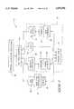
- FIG. 2is a block diagram illustrating a preferred temperature controller according to the invention.
- FIG. 3is a block diagram illustrating operation of a process sequencing subsystem and gas interface.
- FIG. 4is a block diagram illustrating operation of a temperature subsystem.
- FIG. 5is a waveform diagram illustrating an exemplary pseudo-random binary sequence used to characterize the reactor of FIG. 1A.
- FIG. 6is a control diagram of a characterization control mode which uses the pseudo-random binary sequence of FIG. 2 to characterize the reactor of FIG. 1A prior to actual use in processing semiconductor wafers.
- FIG. 7is a control diagram of an element control mode logic circuit, which employs a spike controller.
- FIG. 8is a control diagram of a base control mode logic circuit, which employs a profile controller and the spike controller of FIG. 7.
- FIG. 9is a control diagram of a dynamic control mode logic circuit, which employs a wafer controller, the profile controller of FIG. 8, and the spike controller of FIG. 7.
- FIG. 10is a control diagram of a Dt control mode logic circuit, which employs a Dt non-linear controller, the profile controller of FIG. 8, and the spike controller of FIG. 7.
- FIG. 11is a flowchart illustrating design of the preferred controllers.
- the inventionprovides controllers and methods for controlling a thermal reactor or processor used to process semiconductor workpieces.
- the typical thermal reactorincludes a heating element powered by a power source, and has profile thermocouples and spike thermocouples.
- a preferred methodcomprising the following steps: modeling thermal dynamic characteristics of the thermal reactor, the modeling step including providing thermocouple instrumented wafers in the thermal reactor, perturbing the thermal reactor by controlling the heating element using a stimulation sequence, and developing models based on changes in temperature created by the perturbations, the models including a model of power versus spike thermocouple readings, a model of spike thermocouple readings versus profile thermocouple readings, and a model of profile and spike thermocouple readings versus thermocouple instrumented wafer readings.
- One aspect of the inventionprovides a controller unit for controlling a thermal reactor supporting a heating element powered by a power source, profile thermocouples and spike thermocouples, and selectively receiving thermocouple instrumented wafers, the controller unit comprising an input device receiving a recipe; and a plurality of selectable control mode logic circuits communicating with the profile thermocouples and spike thermocouples, the control mode logic circuits being used to control the heating element relative to the recipe.
- Another aspect of the inventionprovides a method for controlling a thermal reactor including a thermal reactor supporting a heating element powered by a power source, profile thermocouples, and spike thermocouples, and selectively receiving thermocouple instrumented wafers, the method comprising the following steps: modeling thermal dynamic characteristics of the thermal reactor using the profile thermocouples, spike thermocouples, and instrumented wafers; receiving a recipe including desired temperatures with respect to time, and the recipe including desired control modes with respect to time; and switching from one control mode to another in accordance with the recipe, and controlling temperature differently in the different control modes, using temperature information obtained from the profile thermocouples and spike thermocouples.
- controller unitfor controlling a thermal reactor supporting a heating element powered by a power source, profile thermocouples and spike thermocouples, the controller unit comprising: an on-line model which predicts wafer temperature; and a plurality of selectable control mode logic circuits which control the heating element in response to the on-line model, and temperature information obtained from the profile thermocouples, and spike thermocouples during operation.
- Another aspect of the inventionprovides a method of controlling a thermal reactor supporting a heating element powered by a power source, profile thermocouples, and spike thermocouples, the method comprising: controlling energy provided to the thermal reactor relative to desired energy, by using measurements from profile thermocouples and taking the integral of e.sup.(-2/kT) where k is Boltzmann's constant and T is temperature measured using the profile thermocouples.
- controller unitfor controlling a thermal reactor supporting a heating element powered by a power source, profile thermocouples and spike thermocouples
- the controller unitcomprising: a thermal budget controller which controls energy provided to the thermal reactor relative to desired energy, by using measurements from profile thermocouples and taking the integral of e.sup.(-2/kT) where k is Boltzmann's constant and T is temperature measured using the profile thermocouples.
- Another aspect of the inventionprovides a method for controlling a thermal reactor including a thermal reactor supporting a heating element powered by a power source, profile thermocouples and spike thermocouples, the method comprising the following steps: modeling thermal dynamic characteristics of the thermal reactor; receiving a recipe including desired temperatures with respect to time, and the recipe including desired control modes with respect to time; and switching from one control mode to another in accordance with the recipe, and controlling temperature differently in the different control modes, using temperature information provided by the profile thermocouples and spike thermocouples, the control modes being defined by cascaded controllers.
- Another aspect of the inventionprovides a controller unit for controlling a thermal reactor supporting a heating element powered by a power source, profile thermocouples and spike thermocouples, the controller unit comprising: an on-line model which predicts wafer temperature; and a plurality of cascaded selectable control mode logic circuits which control the heating element in response to one or more of: the profile thermocouples, spike thermocouples, and the on-line model.
- Another aspect of the inventionprovides a controller unit for controlling a thermal reactor supporting a heating element powered by a power source, profile thermocouples and spike thermocouples, the controller unit comprising an on-line model which predicts wafer temperature based on measurements from the spike and profile thermocouples; and a plurality of selectable control mode logic circuits, the control mode logic circuits including a base control mode logic circuit having a spike controller which controls power supplied to the heating element in response to measurements by the spike thermocouples, and a profile controller which controls the spike controller in response to measurements by the profile thermocouples; a thermal budget control mode logic circuit which measures energy provided to the thermal reactor and controls energy provided to the thermal reactor with respect to desired energy, the thermal budget control mode logic circuit employing the spike controller, and the profile controller, and the thermal budget control mode logic circuit further including a Dt controller controlling the profile controller; and a dynamic control mode logic circuit which controls energy provided to the thermal reactor based on predicted wafer temperature, the dynamic control mode logic circuit employing the spike controller, the profile controller, and the on-line model
- FIG. 1Ashows a thermal reactor system 10 embodying the invention.
- the thermal reactor system 10includes a thermal reactor 12.
- the thermal reactor 12can either be horizontal or vertical in orientation.
- the thermal reactor 12includes a process tube 14 defining a chamber.
- the process tube 14is preferably made of quartz, or silicon carbide.
- the process tubeis in the general shape of a hollow cylinder having an open end 16.
- the process tube 14has a length which extends along and substantially defines a longitudinal axis.
- the thermal reactor system 10further includes a boat loader or paddle 18 which inserts or removes a wafer load 20 into or from the process tube 14. More particularly, the boat loader 18 includes a support portion 22, and a door portion 24 which is movable with the support portion and which closes the open end of the process tube 14 when the support portion 22 is inserted into the process tube.
- the door portion 24seals and insulates the process tube to prevent heat loss after the wafer load 20 has been inserted into the process tube 14.
- the wafer load 20includes a plurality of boats 26.
- the boats 24are formed of quartz or silicon carbide.
- the wafer load 20further includes a plurality of silicon wafers 26, and each boat 24 supports a plurality of the wafers 26. In the illustrated embodiment, wafers on each boat 24 are equally spaced.
- the boat or boats of wafers 26generally form a wafer or other semiconductor workpiece processing array.
- the thermal reactor 12includes a heating element 30 surrounding the process tube 14.
- the heating element 30is an electrical resistance heating coil or coils extending along the length of the processing chamber parallel to the length of the process tube 14.
- the heating element 30is subdivided into a plurality of separately controllable heating zones 32.
- the zones 32are defined by providing connections along the coil to divide the coil or coils into the separately controllable zones.
- the zonesare then separately controllable by supplying power to opposite ends of each zone associated coil or portion of a larger coil.
- the thermal reactor system 10further includes (FIG. 4) high current voltage transformers 33 and silicon controlled rectifiers (SCRs) 34 for controllably applying power to each of the heating zones 32.
- the thermal reactor 12further includes ceramic insulation 35 encasing the heating element 30.
- the insulationalso serves to reflect and otherwise direct heat toward the wafer array and serves to provide a more uniform layer to minimize heat flux variations away from the processing array.
- the thermal reactor 12further includes a plurality of spike thermocouples 36.
- Thermocouples as the term is used hereinencompasses potentially a variety of temperature sensors, including the more specific meaning of thermocouples. Alternative temperature sensor constructions are intended by the use of the term thermocouples.
- the spike thermocouples 36are placed at a suitable location, such as between the heating element 30 and the process tube 14.
- the spike thermocouples 36are spaced apart along the length of the of the heating element 30, and a spike thermocouple 36 is located in each of the heating zones 32.
- the spike thermocouples 36provide the most specific and responsive indications of the temperature at or of the heating elements in each of the heating zones.
- the thermal reactor 12further includes a profile temperature sensor sheath 38 extending inside the process tube 14.
- the process tube 14has a bottom surface, and the process tube 14 is supported on the bottom surface of the process tube 14 in an orientation parallel to the length of the process tube.
- the sheath 38extends at least partially across each of the heating zones 32.
- the sheath 38is formed of quartz or silicon carbide.
- the thermal reactor 12further includes an elongated profile rod 40 supported in the sheath 38.
- the profile rod 40has a length parallel to the length of the process tube 14.
- the profile rod 40includes a plurality of thermocouples 42 equally spaced apart along the length of the rod 40, and one thermocouple 42 is located in each of the heating zones 32.
- the thermocouples 42are not necessarily aligned with the spike thermocouples 36 in the direction of the length of the process tube 14.
- the profile rod 40measures temperature inside the process tube 14 and provides an indication of the temperature of the wafer load 20 in each of the heating zones.
- thermocouple instrumented wafers 44are optionally employed during modeling of the thermal reactor.
- FIG. 1Bshows the thermal reactor 12 of FIG. 1A receiving the thermocouple instrumented wafers 44 during modeling.
- These thermocouple instrumented wafers 44are uniformly spaced across the wafer load 16 to provide an accurate measurement of the actual temperature of the wafers 28.
- the wafers or other workpiecesbeing formed of silicon or other semiconductor materials being processed.
- Each of the exemplary thermocouple instrumented wafers 44includes a silicon wafer, and two thermocouples 46 bonded to the silicon wafer: one on the edge of the wafer, and one on the center of the wafer.
- the thermocouples 46 of each thermocouple instrumented wafer 44are bonded to the silicon wafer, such as with a ceramic adhesive, to provide accurate temperature measurements.
- the thermal reactor system 10further includes a gas delivery system or gas panel 48 controllably injecting process gases from selectable gas supplies 50 into the process tube 14 to grow, diffuse, or deposit material on the surface of the silicon wafers 28.
- the gas panel 48includes (FIG. 3) valves 52 and mass flow controllers 54.
- the mass flow controllers 52are used to measure and control flows of process gasses into the process tube 14.
- the process tube 14is pressurized for low pressure chemical vapor deposition (LPCVD) processes.
- the thermal reactor 12further includes (FIG. 3) a pressure controller 56.
- the thermal reactor system 10further includes a baratron or other suitable pressure sensing device 58 which measures the pressure in the process tube and communicates the measured pressure to the pressure controller 56.
- the thermal reactor system 10further includes pumps and valves 60, in communication with the pressure controller 56, to achieve the desired pressure in the process tube 14.
- the thermal reactor 12further includes (FIG. 3) a torch 62 internal or external to the process tube 14.
- the torch 62is used for wet oxidation processes by burning a ratio of hydrogen and oxygen to produce steam in the process tube 14.
- the thermal reactor system 10includes (FIG. 2) a control system 64 controlling the thermal reactor 12.
- the control system 64includes two subsystems: a process sequencing subsystem 66 for process sequencing, and a temperature subsystem 68 for temperature control.
- Each subsystem 64 and 66includes a microprocessor, such as an Intel PC, 286, 386, 486, Pentium, or higher, or clone thereof, or Motorola 6800, 68000 or higher, or other microprocessor.
- the process sequencing subsystem 66employs a 6800 microprocessor 70.
- the process sequencing subsystemincludes random access memory 72 and a programmable EPROM 74 that stores controller logic.
- the process sequencing subsystem 66further includes a plurality of digital input and output channels 76 as well as a plurality of analog input and output channels 78.
- the process sequencing subsystem 66further includes a plurality of serial input and output channels 80 for external (remote) communication, if external communication is desired.
- the process sequencing subsystem 66follows a user defined process recipe. More particularly, the thermal reactor system 10 further includes a user interface 82 defining an input device.
- the user interface 82comprises a touch screen terminal interface with which a user can enter a user defined process recipe.
- the usercan define, on a per step basis, step time, gas flows, chamber pressure, temperature setpoints, and ramp rates.
- the temperature subsystem 68includes a 486 microprocessor 84.
- the temperature subsystem 68further includes dynamic random access memory 86 for use with the microprocessor 84.
- the temperature subsystem 68 controller unitincludes four megabytes of dynamic random access memory.
- the temperature subsystem 68 controller unit of the illustrated embodimentfurther includes a two megabyte flash disk 88, a dual ported random access memory 90, a sixteen bit analog to digital converter 92, and a PC/104 bus 94.
- the temperature subsystemincludes a plurality of multivariable controllers 96, 98, 100, and 102 constructed using robust optimal control theory with empirically derived models of the furnace and wafers. More particularly, in the illustrated embodiment, the multivariable controllers 96, 98, 100, and 102 are constructed using H-Infinity control theory.
- control system 64further includes (FIG. 3) a gas panel interface 104 connected between the gas panel 48 and the process sequencing subsystem 68.
- the gas panel interface 104provides the control system 64 with an interface to communicate with the mass flow controllers 54, the gas valves 52, the internal or external torch 62, the pressure controller 56, the boat loader 18, etc.
- the gas panel interface 104includes a plurality of hardware safety interlocks for the thermal reactor (e.g., to ensure hydrogen flow with a proper oxygen to hydrogen ratio, to detect a flame from the torch 62, etc.).
- the control system 64further includes (FIG. 4) a temperature interface connected between the thermocouples 36, 42, and 44 and the temperature subsystem 68. More particularly, in the illustrated embodiment, the temperature interface comprises thermocouple amplifier interface boards 106. In the illustrated embodiment, the temperature subsystem communicates with up to two thermocouple amplifier interfaces: one for measuring spike and profile thermocouples 36 and 42, and one for measuring the thermocouples 46 of the thermocouple instrumented wafers 44 (if thermocouple instrumented wafers are employed). In the illustrated embodiment, the control system 64 further includes (FIG. 4) an element firing interface 108 connected between the heating element 30 and the temperature subsystem 68. The element firing interface 108 includes one firing board for each of the defined heating zones 32. These firing boards use a zero-point switching technique to apply or discontinue power at zero crossings of the voltage waveform.
- a process of designing the controllers 96, 98, 100, and 102is illustrated in detail in FIG. 11.
- a characterization control mode(FIG. 6, and step 110 of FIG. 11) the thermal dynamic characteristics of the thermal reactor are modeled using spike, profile, and wafer temperatures as well as power setpoints during excitation using a random or other stimulation sequence (FIG. 5).
- a pseudo-random binary sequencePRBS
- PRBSpseudo-random binary sequence
- the thermal reactoris brought up to operating temperature and then perturbed using the pseudo-random binary sequence, causing gradual temperature fluctuations in the thermal reactor.
- steps 112a-dmodels are created based on changes in temperature created by the perturbations.
- all modelsare derived using a linear least squares minimum distance system identification technique.
- all modelsare represented and implemented in statespace form.
- off-line modelwhat is meant is a model that is created for control system design.
- on-line modelwhat is meant is a model that is active during the operation of the thermal reactor 12, such as to process actual semiconductor wafers 28.
- three off-line modelsare developed: a power setpoint vs. spike thermocouple model; a spike thermocouple vs. profile thermocouple model; and a profile and spike thermocouple vs. thermocouple instrumented wafer model.
- Each off-line modelis used to design the controllers 96, 98, 100, and 102 in the temperature subsystem.
- a single on-line model 114is developed to estimate wafer temperature during operation of the thermal reactor 12.
- the on-line model 110predicts the actual temperature of the wafers 28 using real temperature measurements from the spike and profile thermocouples 36 and 42. Because modeling of the entire thermal reactor 12 is complicated and very susceptible to variations and maintenance operations over time, simple modeling of the relationship between the wafer temperatures and the measured profile and spike temperatures is performed to provide an accurate indication of the wafer temperatures during dynamic changes in temperature. Further, it is assumed that under steady-state conditions the profile temperatures are indicative of the actual temperatures of the wafers 28.
- the three off-line modelsare used to create three separate and unique controllers: the spike controller 96, the profile controller 98, and the wafer controller 100.
- the spike controller 96uses the difference between the spike setpoints and spike thermocouple measurements as inputs, and then outputs the power setpoints to the firing interface 108.
- the profile controller 98uses the difference between the profile setpoints and the profile measurements as inputs and then outputs spike setpoints to the spike controller 96.
- the wafer controller 100uses the difference between the wafer setpoints and predictions of the on-line wafer temperature model as inputs and then outputs profile setpoints to the profile controller 98.
- each controller 96, 98, and 100is designed using H-Infinity robust optimal control theory. More particularly, in the illustrated embodiment, each of these controllers are multivariable, in which the interaction between heating zones is taken into consideration to provide improved temperature response to the desired ramp or setpoint.
- the design of the controllers 96, 98, and 100will now be described in greater detail.
- the controllers 96, 98, and 100are designed using data obtained from an identification experiment.
- the design procedurecomprises two main steps; namely, system identification and controller design.
- the preferred embodimentemploys high performance numerical analysis software such as MATLAB (TM) and SIMULINK (TM) in modeling and in controller design.
- the system identification or characterization stepinvolves making empirical measurements of the processor temperature response characteristics in response to known thermal input.
- the responseis measured by the spike thermocouples 36, profile thermocouples 42 and the temperature sensing wafers 46.
- the measured response datais analyzed using a suitable analytical technique to achieve a model or models which provide predictive indication of wafer temperatures based upon the spike and profile thermocouple temperatures which can be measured during actual processing of wafers.
- a suitable analytical techniqueto achieve a model or models which provide predictive indication of wafer temperatures based upon the spike and profile thermocouple temperatures which can be measured during actual processing of wafers.
- One preferred technique for deriving the characterization informationinvolves using a least-squares parameter estimation algorithm to obtain estimates of the system parameters which reflect temperature response characteristics.
- the main objectives of this stepare the identification of a system model that describes the input-output data and the estimation of uncertainty bounds that describe the confidence in the model. For this purpose, we consider systems described by the general state-space model:
- Matrix Ahas dimensions n ⁇ n.
- Matrix Bhas dimensions n ⁇ m.
- Matrix Chas dimensions m ⁇ n.
- matrix Dhas dimensions m ⁇ m.
- the coefficients of the matricesare parameters which are derived and potentially adjusted for the particular model being developed to optimize the model's successful operation.
- A-LCis a Hurwitz matrix (see various texts on control theory, such as Kailath, T., Linear Systems, Prentice-Hall, Englewood Cliffs, N.J., 1980).
- Iis the identity matrix and x(o) are the initial conditions of the states.
- ⁇is a vector containing the adjustable parameters ⁇ 1 , ⁇ 2 , d as well as the possibly unknown initial conditions x(0), while w contains the signals (sI-F T ) -1 q T u, (sI-FT) -1 q T y, u, and (sI-F T ) -1 q T .
- the basic system identification stepcomprises the following sub-steps:
- the identification or characterization experimentrelies on the generation of an input signal which provides sufficient excitation to the thermal reactor so as to allow the reliable identification of its parameters.
- excitation signalshave been proposed in the literature (see, for example, Ljung, L., System Identification: Theory for the User, Prentice-Hall, Englewood Cliffs, N.J., 1980).
- PRBSpseudo-random binary sequence
- the identificationis performed in closed-loop. That is, prior information about the thermal reactor to be identified is used to design a simple controller (e.g., proportional or proportional-integral).
- the pseudo-random binary sequence excitationis then fed as a reference input (set-point) to the controller and the resulting control inputs and thermal reactor outputs are measured.
- pseudo-random binary sequencerequires more attention.
- This type of excitationis implemented as a sequence of step changes in the reference commands about the nominal operating condition of the thermal reactor.
- Pseudo-random binary sequencescan be defined by two vectors:
- the first vectorindicates switching times and the second indicates the deviation from the nominal set-point ( ⁇ maximum deviation level).
- the randomness in the pseudo-random binary sequenceenters in the switching times where t i+1 -t i is a random number.
- the maximum level and the minimum and maximum duration of each pulseare the design parameters of a pseudo-random binary sequence. In general, the level should be selected as large enough to provide a good signal-to-noise ratio (SNR) but small enough so as to avoid big deviations from the nominal operating condition, which will introduce interference from the ever-present plant nonlinearities. This is precisely where closed-loop identification has an advantage because even a crude controller will keep the plant response around the nominal within, roughly, the PRBS level.
- SNRsignal-to-noise ratio
- each pseudo-random binary sequence pulseshould be such that the resulting sequence has most of its power around the desired closed-loop bandwidth (and closed-loop crossover) which is where the reactor model should be reliable.
- the total length of the pseudo-random binary sequenceis dictated by memory and experiment-time limitations, but it should be long enough to allow for noise averaging and the observation of the plant response at a sufficient number of frequencies. Roughly, a rule of thumb is to observe the response of the thermal reactor to 7-10 PRBS pulses whose duration is selected according to the previous criteria.
- multiple PRBS inputsmust be generated, one for each channel. These should be further restricted to be independent of each other, in the sense that the resulting regressor vector has a well-conditioned covariance matrix. This requirement does not present a problem when long sequences are used. In practice, however, the limited length of the sequence suggests that the validity of this assumption should be checked and the PRBS regenerated if the condition fails.
- a standard least squares algorithmis used to estimate the parameters of the linear model which are then used to compute the entries of the state-space matrices according to the equations presented above.
- the parameter estimation algorithmis modified in order to improve its reliability and its ability to yield estimates that emphasize the fit of the plant characteristics in a given frequency range (weighted least-squares).
- the latteris achieved in a straightforward manner by filtering the input-output data numerically, with a filter that has a desired frequency response. For example, a low-pass filter could be used in cases of data corrupted by high-frequency noise, while a band-pass filter could be used to enhance the reliability of the identified model around the desired closed-loop bandwidth.
- the success of the identification and the possible redesign of these filtersare judged based on "uncertainty" bounds that are discussed subsequently. It should be emphasized that although some iterations may be required in the parameter estimation step, these do not necessarily require repetition of the identification experiment.
- the estimation stepsolves, in one embodiment, the following problem
- His a weighting matrix
- ⁇is a threshold parameter
- E LSis the error corresponding to the least-squares solution.
- the obtained reactor modelis then checked for minimality using standard reduction algorithms, (see Chiang, R. and M. Safonov, Robust Control Toolbox: User's Manual (For use with MAILAB), The Mathworks Inc., Natick, Mass., 1992) and references therein, and the reliability of the model is quantified by analysis of residuals.
- This stepquantifies confidence in the model and provides constraints that should be met during the controller design step.
- performing a spectral analysis on the estimation errorprovides estimates of the effective multiplicative and feedback uncertainty (see Alexander, C. and K. S. Tsakalis, "Control of an Inverted Pendulum: A Classical Experiment Revisited," Proc. 1995 Western Multiconference, Society for Computer Simulation, Las Vegas, 1995).
- the core of the controller design procedureis the Hoo design approach (see Chiang, R. and M. Safonov, Robust Control Toolbox: User's Manual (For use with MATLAB), The Mathworks Inc., Natick, Mass., 1992), augmented by controller reduction and well-posedness checks. More specifically, the uncertainty bounds resulting from the system identification step are used to define sensitivity and complementary sensitivity weights. These, together with the identified reactor, augmented by integrators, form the so-called super-plant in the format required by standard Hoo computational software. Typically, the resulting Hoo controller is of high order and contains states due to the weights that are essentially irrelevant for its performance and can potentially degrade its reliability, robustness and discretization properties. For this reason, the reduction is performed in three steps.
- the first stepis to remove states that correspond to very fast modes, e.g., two orders of magnitude above the closed-loop bandwidth. Typically, such modes are irrelevant to the controller stability or performance but they create problems in digital implementation since their discrete-time approximation requires high sampling rates.
- the next stepis to remove very slow modes which again contribute very little to the overall closed-loop behavior. Such modes are typically associated with "pole-zero cancellations" near the jw-axis and, if retained, may cause the appearance of small but slowly decaying errors in the tracking performance.
- a standard model order reduction(weighted or not) is performed to eliminate other controller states that have insignificant contribution. The reduction step is a price paid in order to simplify the weight selection step.
- Lis a matrix gain such that the closed-loop system of the controller and L is stable.
- An effective design of Lcan be obtained as an observer gain (see Anderson, B. D. O. and J. B. Moore, Optimal Control: Linear Quadratic Methods, Prentice-Hall, Englewood Cliffs, N.J., 1990).
- the controller-observer gain systemcan be nicely interpreted as the construction of an observer which forces the controller output to track the output of a system that consists of the controller composed with the saturation nonlinearity.
- an evaluation stepis performed via nonlinear simulation of the discretized controller and identified reactor, together with the actuator saturation. This evaluation has been very useful in exposing possible design limitations and assessing the controller capabilities, e.g., in terms of achievable ramp rates. Practical experience indicates that the simulated behavior of the closed loop system is indeed a good approximation of the actual one.
- step 118the spike, profile, and wafer controllers 96, 98, and 100 and the on-line wafer model are implemented in hardware in the temperature subsystem 68.
- a control mode logic circuitis selectable from among different available control mode logic circuits including an element control mode logic circuit (FIG. 7) defining an element control mode, a base control mode logic circuit (FIG. 8) defining a base control mode, a dynamic control mode logic circuit (FIG. 9) defining a dynamic control mode, and a Dt control mode logic circuit (FIG. 10) defining a Dt control mode.
- Each of these control mode logic circuitsare defined by a single one or a combination of the controllers 96, 98, and 100.
- the temperature subsystem 68employs the spike controller 96 for the element control mode (FIG. 7).
- the temperature subsystem 68employs the spike controller 96 injected with the pseudo-random binary sequence for the characterization control mode (FIG. 6).
- the temperature subsystem 68employs a combination of the profile controller 98 and the spike controller 96 for the base control mode (FIG. 8).
- the temperature subsystem 68employs a combination of the wafer controller 100, the profile controller 98, and the spike controller 96 for the dynamic control mode (FIG. 9).
- the temperature subsystem 68employs the non-linear Dt controller 102 with the profile controller 98, and the spike controller 96 to provide the Dt control mode (FIG. 10).
- a usercan provide a recipe comprising multiple steps and which uses any one of the control modes in each step. For example, a user can provide a recipe that switches from one control mode to another at a given stage of semiconductor processing.
- One suggested approachis to employ the base control mode during a furnace check and push in of the boat 18, prior to a ramp up in temperature, to employ the wafer control mode during temperature ramp up and temperature stabilization, to employ the Dt control mode during wafer processing steps, and to employ the base control mode during boat push out.
- Another suggested approachis to use the base control mode during all processing steps.
- the element control modeis typically a maintenance mode (e.g., to burn in elements).
- the spike controllercontrols on the basis of spike thermocouple temperatures.
- the modeis not used in normal processing of wafers.
- the base control mode(FIG. 8) is the default mode of operation.
- the profile controller 98provides a spike setpoint control signal based on a profile error.
- the profile erroris based on the difference between profile temperature setpoint, and profile temperature measurements by the profile thermocouples 42.
- the spike controller 98controls power to the thermal reactor based on spike error.
- the spike erroris based on the difference between spike setpoint and spike temperature measurements by the spike thermocouples 36.
- the base control modeprovides accurate control resulting in improved process uniformity and cycle time reduction attributed to faster stabilization times.
- the base control mode logic circuituses the profile and spike controllers simultaneously by cascading them together.
- Profile thermocouplesdo not match temperatures at the edge of a load. Users prefer not to change their recipes to compensate for this.
- One solution to this problemis to shorten profile thermocouples which results in readings generated by the profile thermocouples more accurately matching temperatures at the edge of a load.
- the dynamic or wafer control mode(FIG. 9) provides a solution to the problem without requiring modification of the profile thermocouples or adjustment of the user's recipe.
- the wafer controller 100provides prediction or estimation of the temperatures of wafers 28 and control to achieve temperatures for the wafers 28 which approach the desired or recipe wafer temperatures.
- the dynamic control modemay be most advantageously employed during temperature ramping and stabilization steps.
- the dynamic control modeinvolves the prior use of the thermocouple instrumented wafers 44 during modeling, as discussed above. After modeling, while the control system is in use, the dynamic control mode controls the thermal reactor 12 based on predicted wafer temperature using the on-line wafer temperature estimating model 114.
- the on-line wafer temperature estimation model 114predicts wafer temperature based on measurements from the spike and profile thermocouples 36 and 42.
- wafer temperatureis predicted based on measurements from the spike and profile thermocouples 36 and 42 and the relationship between measurements taken by the thermocouple instrumented wafers 44 (representing wafer temperature) and measurements taken by the profile and spike thermocouples 36 and 42 during modeling.
- the wafer controller 100provides a profile setpoint based on a wafer error.
- the wafer erroris based on the difference between profile temperature setpoint, and profile temperature measurements by the profile thermocouples 42.
- the profile controllerprovides a spike setpoint control signal based on profile error.
- the profile erroris based on the difference between profile temperature setpoint produced by the wafer controller 100, and profile temperature measurements by the profile thermocouples.
- the spike controllercontrols power to the thermal reactor based on spike error.
- the spike erroris based on the difference between spike setpoint and spike temperature measurements by the spike thermocouples 36.
- the dynamic control modeuses the spike controller 96, the profile controller 98, and the wafer controller 100 cascaded together.
- the Dt controller 102measures temperature exposure or applied thermal energy and controls energy with respect to setpoint or desired energy.
- Thermal budgetis controlled, using measurements from profile thermocouples 42 and taking the integral of e.sup.(-2/kT) where k is Boltzmann's constant and T is temperature measured using the profile thermocouples 42, to maintain Dt values in accordance with desired energy.
- a calculationis made of energy sent into the thermal reactor, and energy sent into the thermal reactor is controlled.
- the thermal budget modeis advantageously used to control thermal budget during critical processing steps to maintain consistent Dt values both down the load and run-to-run.
- the Dt controller 102provides a profile setpoint based on an energy error.
- the energy erroris based on the difference between an energy setpoint, and measured energy.
- the profile controller 98provides a spike setpoint control signal based on a profile error.
- the profile erroris based on the difference between profile temperature setpoint produced by the Dt controller, and profile temperature measurements by the profile thermocouples 42.
- the spike controller 96controls power to the thermal reactor based on spike error.
- the spike erroris based on the difference between spike setpoint and spike temperature measurement by the spike thermocouples 36.
Landscapes
- Engineering & Computer Science (AREA)
- Chemical & Material Sciences (AREA)
- General Physics & Mathematics (AREA)
- Physics & Mathematics (AREA)
- Metallurgy (AREA)
- Automation & Control Theory (AREA)
- Chemical Kinetics & Catalysis (AREA)
- General Chemical & Material Sciences (AREA)
- Organic Chemistry (AREA)
- Materials Engineering (AREA)
- Health & Medical Sciences (AREA)
- Microelectronics & Electronic Packaging (AREA)
- Remote Sensing (AREA)
- Toxicology (AREA)
- Condensed Matter Physics & Semiconductors (AREA)
- Manufacturing & Machinery (AREA)
- Computer Hardware Design (AREA)
- Crystallography & Structural Chemistry (AREA)
- Power Engineering (AREA)
- Mechanical Engineering (AREA)
- Feedback Control In General (AREA)
- Control Of Temperature (AREA)
- Control Of Resistance Heating (AREA)
- Physical Vapour Deposition (AREA)
Abstract
Description
x=Ax+Bu; y=Cx+Du
x=(A-LC)x+(B-LD)u+Ly; y=Cx+Du
x=Fx+θ.sub.1 u+θ.sub.2 y; y=qx+du
sIx(s)-x(0)=Fx(s)+θ.sub.1 u(s)+θ.sub.2 y(s); y(s)=qx(s)+du(s)
x(s)=(sI-Fx).sup.-1 θ.sub.1 u(s)+θ.sub.2 y(s)+x(0)!
y(s)=q(sI-Fx).sup.-1 θ.sub.1 u(s)+θ.sub.2 y(s)+x(0)!+du(s)
y(s)= q(sI-Fx).sup.-1 θ.sub.1 +d!u(s)+q(sI-F).sup.-1 θ.sub.2 y(s)+q(sI-F).sup.-1 x(0)
y(s)=θ.sub.1.sup.T (sI-F.sup.T).sup.-1 q.sup.T u(s)+θ.sub.2T (sI-F.sup.T).sup.-1 q.sup.T y(s)+du(s)+x(0).sup.T (sI-F.sup.T).sup.-1 q.sup.T
y=θ.sup.T w
t.sub.1,t.sub.2,Λ!, m.sub.1,m.sub.2,Λ!
min∥Hθ∥, subject to: ∥y-θw∥≦(1+ρ)E.sub.LS
v=Lud(u)
Claims (12)
Priority Applications (8)
| Application Number | Priority Date | Filing Date | Title |
|---|---|---|---|
| US08/791,024US5895596A (en) | 1997-01-27 | 1997-01-27 | Model based temperature controller for semiconductor thermal processors |
| AU62446/98AAU6244698A (en) | 1997-01-27 | 1998-01-27 | Model based temperature controller for semiconductor thermal processors |
| JP53465498AJP3775753B2 (en) | 1997-01-27 | 1998-01-27 | Model-based temperature controller for semiconductor thermal processing machines |
| CN98803362ACN1250587A (en) | 1997-01-27 | 1998-01-27 | Model based temperature controller for semiconductor thermal processors |
| KR1019997006777AKR100359734B1 (en) | 1997-01-27 | 1998-01-27 | Model based temperature controller for semiconductor thermal processors |
| EP98904607AEP0954948A4 (en) | 1997-01-27 | 1998-01-27 | Model based temperature controller for semiconductor thermal processors |
| PCT/US1998/001076WO1998035531A1 (en) | 1997-01-27 | 1998-01-27 | Model based temperature controller for semiconductor thermal processors |
| TW087102321ATW376532B (en) | 1997-01-27 | 1998-02-19 | Model based temperature controller for semiconductor thermal processors |
Applications Claiming Priority (1)
| Application Number | Priority Date | Filing Date | Title |
|---|---|---|---|
| US08/791,024US5895596A (en) | 1997-01-27 | 1997-01-27 | Model based temperature controller for semiconductor thermal processors |
Publications (1)
| Publication Number | Publication Date |
|---|---|
| US5895596Atrue US5895596A (en) | 1999-04-20 |
Family
ID=25152435
Family Applications (1)
| Application Number | Title | Priority Date | Filing Date |
|---|---|---|---|
| US08/791,024Expired - Fee RelatedUS5895596A (en) | 1997-01-27 | 1997-01-27 | Model based temperature controller for semiconductor thermal processors |
Country Status (8)
| Country | Link |
|---|---|
| US (1) | US5895596A (en) |
| EP (1) | EP0954948A4 (en) |
| JP (1) | JP3775753B2 (en) |
| KR (1) | KR100359734B1 (en) |
| CN (1) | CN1250587A (en) |
| AU (1) | AU6244698A (en) |
| TW (1) | TW376532B (en) |
| WO (1) | WO1998035531A1 (en) |
Cited By (40)
| Publication number | Priority date | Publication date | Assignee | Title |
|---|---|---|---|---|
| US6207937B1 (en) | 1998-05-11 | 2001-03-27 | Semitool, Inc. | Temperature control system for a thermal reactor |
| DE10032465A1 (en)* | 2000-07-04 | 2002-01-31 | Steag Rtp Systems Gmbh | Method and device for the thermal treatment of objects |
| WO2002026435A1 (en)* | 2000-09-27 | 2002-04-04 | Emcore Corporation | Apparatus and method for controlling temperature uniformity of substrates |
| US20020040250A1 (en)* | 2000-08-21 | 2002-04-04 | Gaikwad Sujit V. | Auto-tuning controller using loop-shaping |
| US20020045146A1 (en)* | 2000-09-13 | 2002-04-18 | Wenling Wang | Batch-type heat treatment apparatus and control method for the batch-type heat treatment apparatus |
| US6375749B1 (en) | 1999-07-14 | 2002-04-23 | Seh America, Inc. | Susceptorless semiconductor wafer support and reactor system for epitaxial layer growth |
| WO2002034451A1 (en)* | 2000-10-25 | 2002-05-02 | Tokyo Electron Limited | Method of and structure for controlling electrode temperature |
| US6395085B2 (en) | 1999-07-14 | 2002-05-28 | Seh America, Inc. | Purity silicon wafer for use in advanced semiconductor devices |
| US20020062792A1 (en)* | 1999-07-14 | 2002-05-30 | Seh America, Inc. | Wafer support device and reactor system for epitaxial layer growth |
| US20020074324A1 (en)* | 2000-09-27 | 2002-06-20 | Wenling Wang | Heat treatment apparatus and controller for heat treatment apparatus and control method for heat treatment apparatus |
| US6454852B2 (en) | 1999-07-14 | 2002-09-24 | Seh America, Inc. | High efficiency silicon wafer optimized for advanced semiconductor devices |
| US6461438B1 (en)* | 1999-11-18 | 2002-10-08 | Tokyo Electron Limited | Heat treatment unit, cooling unit and cooling treatment method |
| US20030014145A1 (en)* | 2001-07-16 | 2003-01-16 | Applied Materials, Inc. | Integration of fault detection with run-to-run control |
| US20030041802A1 (en)* | 2001-08-31 | 2003-03-06 | Kabushiki Kaisha Toshiba | Vacuum pumping system and method for monitoring of the same |
| WO2002067297A3 (en)* | 2000-12-06 | 2003-03-27 | Advanced Micro Devices Inc | Run-to-run control method for proportional-integral-derivative (pid) controller tuning for rapid thermal processing (rtp) |
| US6606537B1 (en)* | 2001-04-19 | 2003-08-12 | Kic Thermal Profiling | Method for correcting process temperature profile in a multi-zone thermal processor |
| US6627860B1 (en)* | 2001-11-08 | 2003-09-30 | Nat Semiconductor Corp | System and method of temperature management for semiconductor material processing |
| US6632277B2 (en) | 1999-07-14 | 2003-10-14 | Seh America, Inc. | Optimized silicon wafer gettering for advanced semiconductor devices |
| US20040005147A1 (en)* | 2000-07-24 | 2004-01-08 | Wenling Wang | Heat treatment apparatus, calibration method for temperature measuring system of the apparatus, and heat treatment system |
| US20040098145A1 (en)* | 2002-11-14 | 2004-05-20 | Liu Zhenduo | Hybrid cascade model-based predictive control system |
| US6753512B1 (en)* | 2002-01-02 | 2004-06-22 | Simtek, Inc. | Model-based control system for thermally treating webs |
| US20040121495A1 (en)* | 2002-12-18 | 2004-06-24 | Sonderman Thomas J. | Dynamic adaptive sampling rate for model prediction |
| US20040137755A1 (en)* | 2002-06-06 | 2004-07-15 | Thermal Acquisition Corp. | System and method for hydrogen-rich selective oxidation |
| US20060100735A1 (en)* | 2002-12-23 | 2006-05-11 | Markus Hauf | Process for determining the temperature of a semiconductor wafer in a rapid heating unit |
| US7087443B2 (en) | 2003-07-29 | 2006-08-08 | Brooks Automation, Inc. | Optimized temperature controller for cold mass introduction |
| US20070282480A1 (en)* | 2003-11-10 | 2007-12-06 | Pannese Patrick D | Methods and systems for controlling a semiconductor fabrication process |
| US20080155442A1 (en)* | 2003-11-10 | 2008-06-26 | Pannese Patrick D | Methods and systems for controlling a semiconductor fabrication process |
| US20090230115A1 (en)* | 2008-03-13 | 2009-09-17 | Tokio Shino | Peb apparatus and control method |
| US20090292506A1 (en)* | 2004-07-10 | 2009-11-26 | Kla-Tencor Corporation | Methods of and apparatuses for maintenance, diagnosis, and optimization of processes |
| US20100012035A1 (en)* | 2006-09-11 | 2010-01-21 | Hiroshi Nagata | Vacuum vapor processing apparatus |
| US20120094010A1 (en)* | 2010-10-18 | 2012-04-19 | Hitachi Kokusai Electric Inc. | Substrate processing apparatus, temperature controlling method of substrate processing apparatus, and heating method of substrate processing apparatus |
| US20130260039A1 (en)* | 2012-03-29 | 2013-10-03 | Tokyo Electron Limited | Heat treatment system, heat treatment method, and non-transitory computer-readable recording medium |
| DE10329107B4 (en)* | 2002-12-23 | 2015-05-28 | Mattson Thermal Products Gmbh | Method for determining at least one state variable from a model of an RTP system |
| US20160363373A1 (en)* | 2015-06-10 | 2016-12-15 | Tokyo Electron Limited | Heat treatment apparatus, regulation method of heat treatment apparatus, and program |
| US20180040484A1 (en)* | 2016-08-05 | 2018-02-08 | Tokyo Electron Limited | Semiconductor system |
| US10061331B2 (en) | 2015-01-22 | 2018-08-28 | Qualcomm Incorporated | Systems and methods for detecting thermal runaway |
| US10086511B2 (en) | 2003-11-10 | 2018-10-02 | Brooks Automation, Inc. | Semiconductor manufacturing systems |
| US10409303B2 (en)* | 2016-03-16 | 2019-09-10 | Kelk Ltd. | Temperature controller of semiconductor wafer and temperature control method of semiconductor wafer |
| US11248295B2 (en) | 2014-01-27 | 2022-02-15 | Veeco Instruments Inc. | Wafer carrier having retention pockets with compound radii for chemical vapor deposition systems |
| CN120178981A (en)* | 2025-05-22 | 2025-06-20 | 中国计量大学 | A nonlinear model prediction temperature control method for semiconductor temperature control synthesis reactor |
Families Citing this family (16)
| Publication number | Priority date | Publication date | Assignee | Title |
|---|---|---|---|---|
| JP2002523908A (en)* | 1998-08-26 | 2002-07-30 | セミトゥール・インコーポレイテッド | Low-temperature process for forming an epitaxial layer on a semiconductor substrate |
| DE19855637A1 (en)* | 1998-12-02 | 2000-06-15 | Aixtron Ag | Process and system for semiconductor crystal production with temperature management |
| DE10335460B4 (en)* | 2003-08-02 | 2008-02-28 | Infineon Technologies Ag | Method for operating a CVD system |
| JP2006113724A (en)* | 2004-10-13 | 2006-04-27 | Omron Corp | Control method, temperature control method, temperature regulator, heat treatment equipment, program and recording medium |
| US7751908B2 (en)* | 2004-12-02 | 2010-07-06 | Taiwan Semiconductor Manufacturing Co., Ltd. | Method and system for thermal process control |
| US20060137377A1 (en) | 2004-12-29 | 2006-06-29 | Samson Eric C | Method and apparatus for external processor thermal control |
| US7838072B2 (en)* | 2005-01-26 | 2010-11-23 | Tokyo Electron Limited | Method and apparatus for monolayer deposition (MLD) |
| US7459175B2 (en)* | 2005-01-26 | 2008-12-02 | Tokyo Electron Limited | Method for monolayer deposition |
| US20120168143A1 (en)* | 2010-12-30 | 2012-07-05 | Poole Ventura, Inc. | Thermal Diffusion Chamber With Heat Exchanger |
| CN103034265B (en)* | 2012-12-11 | 2015-03-25 | 北京兴华机械厂 | Temperature controller evening temperature in force and adjusting temperature by semiconductor chilling plates and used for testing inertia type instrument |
| US9375884B2 (en)* | 2014-04-15 | 2016-06-28 | The Boeing Company | Optical scanner and projection apparatus for thermal management of composite repairs |
| JP6858077B2 (en)* | 2017-05-25 | 2021-04-14 | アズビル株式会社 | Controller adjustment system and adjustment method |
| CN207243986U (en)* | 2017-10-16 | 2018-04-17 | 君泰创新(北京)科技有限公司 | Vacuum coating equipment |
| CN107885253B (en)* | 2017-11-21 | 2024-05-03 | 中国工程物理研究院电子工程研究所 | Precise temperature control device for semiconductor device dose rate effect experiment |
| CN114879779B (en)* | 2022-05-31 | 2023-09-01 | 成都中远创视科技有限公司 | Temperature control circuit based on filter |
| KR102759661B1 (en) | 2023-11-20 | 2025-01-24 | 주식회사 유진테크 | Substrate processing apparatus and substrate processing method |
Citations (10)
| Publication number | Priority date | Publication date | Assignee | Title |
|---|---|---|---|---|
| US4276603A (en)* | 1979-10-30 | 1981-06-30 | Btu Engineering Corporation | Diffusion furnace microcontroller |
| US4688180A (en)* | 1984-12-19 | 1987-08-18 | Ohkura Electric Co., Ltd. | Pattern-switching temperature control apparatus |
| US4711989A (en)* | 1986-05-19 | 1987-12-08 | Thermco Systems, Inc. | Diffusion furnace multizone temperature control |
| US4761538A (en)* | 1985-11-21 | 1988-08-02 | Dainippon Screen Mfg. Co., Ltd. | Method and apparatus for controlling the temperature of a radiantly heated object |
| US4937434A (en)* | 1988-02-24 | 1990-06-26 | Tel Sagami Limited | Heat treatment apparatus and heat treatment method |
| US5099442A (en)* | 1989-11-04 | 1992-03-24 | Ohkura Electric Co., Ltd. | Furnace temperature control apparatus using adjustment input |
| US5258601A (en)* | 1990-10-30 | 1993-11-02 | Shimadzu Corporation | Capillary rheometer with temperature controller for maintaining uniform temperature distribution of sample |
| US5280422A (en)* | 1990-11-05 | 1994-01-18 | Watlow/Winona, Inc. | Method and apparatus for calibrating and controlling multiple heaters |
| US5291514A (en)* | 1991-07-15 | 1994-03-01 | International Business Machines Corporation | Heater autotone control apparatus and method |
| WO1996012386A1 (en)* | 1994-10-17 | 1996-04-25 | Relman, Inc. | Thermal reactor optimization |
Family Cites Families (5)
| Publication number | Priority date | Publication date | Assignee | Title |
|---|---|---|---|---|
| JPS59108119A (en)* | 1982-12-13 | 1984-06-22 | Hitachi Ltd | On-line measuring and controlling system of furnace temperature |
| JP2657218B2 (en)* | 1987-10-21 | 1997-09-24 | 東京エレクトロン株式会社 | Heat treatment equipment |
| US4886954A (en)* | 1988-04-15 | 1989-12-12 | Thermco Systems, Inc. | Hot wall diffusion furnace and method for operating the furnace |
| JPH03145122A (en)* | 1989-10-31 | 1991-06-20 | Toshiba Corp | Temperature control device for semiconductor heat treatment equipment |
| JPH05152311A (en)* | 1991-12-02 | 1993-06-18 | Matsushita Electric Ind Co Ltd | Manufacture of semiconductor device and semiconductor manufacturing device |
- 1997
- 1997-01-27USUS08/791,024patent/US5895596A/ennot_activeExpired - Fee Related
- 1998
- 1998-01-27KRKR1019997006777Apatent/KR100359734B1/ennot_activeExpired - Fee Related
- 1998-01-27WOPCT/US1998/001076patent/WO1998035531A1/enactiveIP Right Grant
- 1998-01-27CNCN98803362Apatent/CN1250587A/enactivePending
- 1998-01-27AUAU62446/98Apatent/AU6244698A/ennot_activeAbandoned
- 1998-01-27EPEP98904607Apatent/EP0954948A4/ennot_activeWithdrawn
- 1998-01-27JPJP53465498Apatent/JP3775753B2/ennot_activeExpired - Fee Related
- 1998-02-19TWTW087102321Apatent/TW376532B/ennot_activeIP Right Cessation
Patent Citations (11)
| Publication number | Priority date | Publication date | Assignee | Title |
|---|---|---|---|---|
| US4276603A (en)* | 1979-10-30 | 1981-06-30 | Btu Engineering Corporation | Diffusion furnace microcontroller |
| US4688180A (en)* | 1984-12-19 | 1987-08-18 | Ohkura Electric Co., Ltd. | Pattern-switching temperature control apparatus |
| US4761538A (en)* | 1985-11-21 | 1988-08-02 | Dainippon Screen Mfg. Co., Ltd. | Method and apparatus for controlling the temperature of a radiantly heated object |
| US4711989A (en)* | 1986-05-19 | 1987-12-08 | Thermco Systems, Inc. | Diffusion furnace multizone temperature control |
| US4937434A (en)* | 1988-02-24 | 1990-06-26 | Tel Sagami Limited | Heat treatment apparatus and heat treatment method |
| US5099442A (en)* | 1989-11-04 | 1992-03-24 | Ohkura Electric Co., Ltd. | Furnace temperature control apparatus using adjustment input |
| US5258601A (en)* | 1990-10-30 | 1993-11-02 | Shimadzu Corporation | Capillary rheometer with temperature controller for maintaining uniform temperature distribution of sample |
| US5280422A (en)* | 1990-11-05 | 1994-01-18 | Watlow/Winona, Inc. | Method and apparatus for calibrating and controlling multiple heaters |
| US5291514A (en)* | 1991-07-15 | 1994-03-01 | International Business Machines Corporation | Heater autotone control apparatus and method |
| WO1996012386A1 (en)* | 1994-10-17 | 1996-04-25 | Relman, Inc. | Thermal reactor optimization |
| US5517594A (en)* | 1994-10-17 | 1996-05-14 | Relman, Inc. | Thermal reactor optimization |
Non-Patent Citations (26)
| Title |
|---|
| "Adaptive Temperature Control of Industrial Diffusion/LPCVD Reactors", by H. De Waard & W.K. De Koning, IFAC Intelligent Tuning and Adaptive Control, Singapore, 1991. |
| "Appendix 4A: Identifiability of Black-Box Multivariable Model Structures", Models of Linear Time-Invariant Systems, pp. 114-126. |
| "Control of MMST RTP: Repeatability, Uniformity, and Integration for Flexible Manufacturing", by Charles Schaper et al., IEEE Transactions on Semiconductor Manufacturing, pp. 1-24 and drawings. |
| "Frequency Shaping", Chapter 9, pp. 262-289. |
| "Model Identification in Rapid Thermal Processing Systems", by Young Man Cho & Thomas Kailath--IEEE Transactions on Semiconductor Manufacturing, Aug. 1993, pp. 233-245. |
| "Modeling, Identification, and Control of Rapid Thermal Processing Systems", by Charles Schaper et al., Journal of the Electrochemical Society, Sep. 1993, pp. 1-29 and drawings. |
| "Optimal Control of the Wafer Temperatures in Diffusion/LPCVD Reactors", by H. De Waard and W.L. De Koning, pp. 243-252, 1992--International Federation of Automatic Control. |
| "Optimization of Transient Temperature Uniformity in RTP Systems", by Stephen Norman, IEEE Transactions on Electron Devices, Jan. 1992, pp. 205-207. |
| "Optimization Problems for Dynamic Systems", Chapter 2, pp. 42-89. "Optimization Problems for Dynamic Systems with Path Constraints", Chapter 3, pp. 90-127. |
| "Temperature Distribution in Semiconductor Wafers Heated in a Vertical Diffusion Furnace", by Shigeki Hirasawa et al., IEEE Transactions on Semiconductor Manufacturing, Aug. 1993, pp. 226-232. |
| Adaptive Temperature Control of Industrial Diffusion/LPCVD Reactors , by H. De Waard & W.K. De Koning, IFAC Intelligent Tuning and Adaptive Control, Singapore, 1991.* |
| Appendix 4A: Identifiability of Black Box Multivariable Model Structures , Models of Linear Time Invariant Systems, pp. 114 126.* |
| B. J. Van Schravendijk et al., "Modeling and control of the wafer temperatures in a diffusion furnace", Journal of Applied Physics, Feb. 15, 1987, pp. 1620-1627. |
| B. J. Van Schravendijk et al., Modeling and control of the wafer temperatures in a diffusion furnace , Journal of Applied Physics, Feb. 15, 1987, pp. 1620 1627.* |
| Chapter 8, "System Identification", pp. 349-416. Chapter 9, "Multivariable and Optimal Control", pp. 417-483. |
| Chapter 8, System Identification , pp. 349 416. Chapter 9, Multivariable and Optimal Control , pp. 417 483.* |
| Control of MMST RTP: Repeatability, Uniformity, and Integration for Flexible Manufacturing , by Charles Schaper et al., IEEE Transactions on Semiconductor Manufacturing, pp. 1 24 and drawings.* |
| Frequency Shaping , Chapter 9, pp. 262 289.* |
| Model Identification in Rapid Thermal Processing Systems , by Young Man Cho & Thomas Kailath IEEE Transactions on Semiconductor Manufacturing, Aug. 1993, pp. 233 245.* |
| Modeling, Identification, and Control of Rapid Thermal Processing Systems , by Charles Schaper et al., Journal of the Electrochemical Society, Sep. 1993, pp. 1 29 and drawings.* |
| Optimal Control of the Wafer Temperatures in Diffusion/LPCVD Reactors , by H. De Waard and W.L. De Koning, pp. 243 252, 1992 International Federation of Automatic Control.* |
| Optimization of Transient Temperature Uniformity in RTP Systems , by Stephen Norman, IEEE Transactions on Electron Devices, Jan. 1992, pp. 205 207.* |
| Optimization Problems for Dynamic Systems , Chapter 2, pp. 42 89. Optimization Problems for Dynamic Systems with Path Constraints , Chapter 3, pp. 90 127.* |
| T.A. Badgwell et al., "In situ measurement of wafer temperature in a low pressure chemical vapor deposition furnace", American Institute of Physics, pp. 1129-1133. |
| T.A. Badgwell et al., In situ measurement of wafer temperature in a low pressure chemical vapor deposition furnace , American Institute of Physics, pp. 1129 1133.* |
| Temperature Distribution in Semiconductor Wafers Heated in a Vertical Diffusion Furnace , by Shigeki Hirasawa et al., IEEE Transactions on Semiconductor Manufacturing, Aug. 1993, pp. 226 232.* |
Cited By (75)
| Publication number | Priority date | Publication date | Assignee | Title |
|---|---|---|---|---|
| US6441350B1 (en) | 1998-05-11 | 2002-08-27 | Brooks Automation Inc. | Temperature control system for a thermal reactor |
| US6211495B1 (en)* | 1998-05-11 | 2001-04-03 | Semitool, Inc. | Temperature control system for a thermal reactor |
| US6222164B1 (en) | 1998-05-11 | 2001-04-24 | Semitool, Inc. | Temperature control system for a thermal reactor |
| US6207937B1 (en) | 1998-05-11 | 2001-03-27 | Semitool, Inc. | Temperature control system for a thermal reactor |
| US6632277B2 (en) | 1999-07-14 | 2003-10-14 | Seh America, Inc. | Optimized silicon wafer gettering for advanced semiconductor devices |
| US6454852B2 (en) | 1999-07-14 | 2002-09-24 | Seh America, Inc. | High efficiency silicon wafer optimized for advanced semiconductor devices |
| US20020062792A1 (en)* | 1999-07-14 | 2002-05-30 | Seh America, Inc. | Wafer support device and reactor system for epitaxial layer growth |
| US6375749B1 (en) | 1999-07-14 | 2002-04-23 | Seh America, Inc. | Susceptorless semiconductor wafer support and reactor system for epitaxial layer growth |
| US6395085B2 (en) | 1999-07-14 | 2002-05-28 | Seh America, Inc. | Purity silicon wafer for use in advanced semiconductor devices |
| US6686571B2 (en) | 1999-11-18 | 2004-02-03 | Tokyo Electron Limited | Heat treatment unit, cooling unit and cooling treatment method |
| US6461438B1 (en)* | 1999-11-18 | 2002-10-08 | Tokyo Electron Limited | Heat treatment unit, cooling unit and cooling treatment method |
| KR100710982B1 (en)* | 1999-11-18 | 2007-04-24 | 동경 엘렉트론 주식회사 | Cooling treatment unit and cooling treatment method |
| US6775471B2 (en) | 2000-07-04 | 2004-08-10 | Mattson Thermal Products Gmbh | Method and device for thermally treating objects |
| DE10032465A1 (en)* | 2000-07-04 | 2002-01-31 | Steag Rtp Systems Gmbh | Method and device for the thermal treatment of objects |
| US6922522B2 (en)* | 2000-07-24 | 2005-07-26 | Tokyo Electron Limited | Heat treatment apparatus, calibration method for temperature measuring system of the apparatus, and heat treatment system |
| US20040005147A1 (en)* | 2000-07-24 | 2004-01-08 | Wenling Wang | Heat treatment apparatus, calibration method for temperature measuring system of the apparatus, and heat treatment system |
| US7024253B2 (en) | 2000-08-21 | 2006-04-04 | Honeywell International Inc. | Auto-tuning controller using loop-shaping |
| US20020040250A1 (en)* | 2000-08-21 | 2002-04-04 | Gaikwad Sujit V. | Auto-tuning controller using loop-shaping |
| US20020045146A1 (en)* | 2000-09-13 | 2002-04-18 | Wenling Wang | Batch-type heat treatment apparatus and control method for the batch-type heat treatment apparatus |
| US6803548B2 (en)* | 2000-09-13 | 2004-10-12 | Tokyo Electron Limited | Batch-type heat treatment apparatus and control method for the batch-type heat treatment apparatus |
| US6492625B1 (en) | 2000-09-27 | 2002-12-10 | Emcore Corporation | Apparatus and method for controlling temperature uniformity of substrates |
| US6847015B2 (en)* | 2000-09-27 | 2005-01-25 | Tokyo Electron Limited | Heat treatment apparatus and controller for heat treatment apparatus and control method for heat treatment apparatus |
| WO2002026435A1 (en)* | 2000-09-27 | 2002-04-04 | Emcore Corporation | Apparatus and method for controlling temperature uniformity of substrates |
| US20020074324A1 (en)* | 2000-09-27 | 2002-06-20 | Wenling Wang | Heat treatment apparatus and controller for heat treatment apparatus and control method for heat treatment apparatus |
| US7075031B2 (en) | 2000-10-25 | 2006-07-11 | Tokyo Electron Limited | Method of and structure for controlling electrode temperature |
| US20040011770A1 (en)* | 2000-10-25 | 2004-01-22 | Strang Eric J. | Method of and structure for controlling electrode temperature |
| WO2002034451A1 (en)* | 2000-10-25 | 2002-05-02 | Tokyo Electron Limited | Method of and structure for controlling electrode temperature |
| WO2002067297A3 (en)* | 2000-12-06 | 2003-03-27 | Advanced Micro Devices Inc | Run-to-run control method for proportional-integral-derivative (pid) controller tuning for rapid thermal processing (rtp) |
| US6819963B2 (en) | 2000-12-06 | 2004-11-16 | Advanced Micro Devices, Inc. | Run-to-run control method for proportional-integral-derivative (PID) controller tuning for rapid thermal processing (RTP) |
| US6606537B1 (en)* | 2001-04-19 | 2003-08-12 | Kic Thermal Profiling | Method for correcting process temperature profile in a multi-zone thermal processor |
| US20030014145A1 (en)* | 2001-07-16 | 2003-01-16 | Applied Materials, Inc. | Integration of fault detection with run-to-run control |
| US7337019B2 (en)* | 2001-07-16 | 2008-02-26 | Applied Materials, Inc. | Integration of fault detection with run-to-run control |
| US20030041802A1 (en)* | 2001-08-31 | 2003-03-06 | Kabushiki Kaisha Toshiba | Vacuum pumping system and method for monitoring of the same |
| US6627860B1 (en)* | 2001-11-08 | 2003-09-30 | Nat Semiconductor Corp | System and method of temperature management for semiconductor material processing |
| US6753512B1 (en)* | 2002-01-02 | 2004-06-22 | Simtek, Inc. | Model-based control system for thermally treating webs |
| US20040137755A1 (en)* | 2002-06-06 | 2004-07-15 | Thermal Acquisition Corp. | System and method for hydrogen-rich selective oxidation |
| US20040098145A1 (en)* | 2002-11-14 | 2004-05-20 | Liu Zhenduo | Hybrid cascade model-based predictive control system |
| US7006900B2 (en)* | 2002-11-14 | 2006-02-28 | Asm International N.V. | Hybrid cascade model-based predictive control system |
| US8017411B2 (en)* | 2002-12-18 | 2011-09-13 | GlobalFoundries, Inc. | Dynamic adaptive sampling rate for model prediction |
| US20040121495A1 (en)* | 2002-12-18 | 2004-06-24 | Sonderman Thomas J. | Dynamic adaptive sampling rate for model prediction |
| US7412299B2 (en) | 2002-12-23 | 2008-08-12 | Mattson Thermal Products Gmbh | Process for determining the temperature of a semiconductor wafer in a rapid heating unit |
| DE10329107B4 (en)* | 2002-12-23 | 2015-05-28 | Mattson Thermal Products Gmbh | Method for determining at least one state variable from a model of an RTP system |
| US20060100735A1 (en)* | 2002-12-23 | 2006-05-11 | Markus Hauf | Process for determining the temperature of a semiconductor wafer in a rapid heating unit |
| US7087443B2 (en) | 2003-07-29 | 2006-08-08 | Brooks Automation, Inc. | Optimized temperature controller for cold mass introduction |
| US20080155442A1 (en)* | 2003-11-10 | 2008-06-26 | Pannese Patrick D | Methods and systems for controlling a semiconductor fabrication process |
| US8775148B2 (en) | 2003-11-10 | 2014-07-08 | Brooks Automation, Inc. | Methods and systems for controlling a semiconductor fabrication process |
| US20080155445A1 (en)* | 2003-11-10 | 2008-06-26 | Pannese Patrick D | Methods and systems for controlling a semiconductor fabrication process |
| US20080155446A1 (en)* | 2003-11-10 | 2008-06-26 | Pannese Patrick D | Methods and systems for controlling a semiconductor fabrication process |
| US20080155443A1 (en)* | 2003-11-10 | 2008-06-26 | Pannese Patrick D | Methods and systems for controlling a semiconductor fabrication process |
| US10444749B2 (en) | 2003-11-10 | 2019-10-15 | Brooks Automation, Inc. | Methods and systems for controlling a semiconductor fabrication process |
| US20070282480A1 (en)* | 2003-11-10 | 2007-12-06 | Pannese Patrick D | Methods and systems for controlling a semiconductor fabrication process |
| US8972029B2 (en)* | 2003-11-10 | 2015-03-03 | Brooks Automation, Inc. | Methods and systems for controlling a semiconductor fabrication process |
| US20080155447A1 (en)* | 2003-11-10 | 2008-06-26 | Pannese Patrick D | Methods and systems for controlling a semiconductor fabrication process |
| US10086511B2 (en) | 2003-11-10 | 2018-10-02 | Brooks Automation, Inc. | Semiconductor manufacturing systems |
| US8639489B2 (en) | 2003-11-10 | 2014-01-28 | Brooks Automation, Inc. | Methods and systems for controlling a semiconductor fabrication process |
| US8442667B2 (en) | 2003-11-10 | 2013-05-14 | Brooks Automation, Inc. | Applications of neural networks |
| US8473270B2 (en) | 2003-11-10 | 2013-06-25 | Brooks Automation, Inc. | Methods and systems for controlling a semiconductor fabrication process |
| US20080147580A1 (en)* | 2003-11-10 | 2008-06-19 | Pannese Patrick D | Applications of neural networks |
| US8612198B2 (en) | 2003-11-10 | 2013-12-17 | Brooks Automation, Inc. | Methods and systems for controlling a semiconductor fabrication process |
| US20090292506A1 (en)* | 2004-07-10 | 2009-11-26 | Kla-Tencor Corporation | Methods of and apparatuses for maintenance, diagnosis, and optimization of processes |
| US8375891B2 (en)* | 2006-09-11 | 2013-02-19 | Ulvac, Inc. | Vacuum vapor processing apparatus |
| US20100012035A1 (en)* | 2006-09-11 | 2010-01-21 | Hiroshi Nagata | Vacuum vapor processing apparatus |
| US20090230115A1 (en)* | 2008-03-13 | 2009-09-17 | Tokio Shino | Peb apparatus and control method |
| US20120094010A1 (en)* | 2010-10-18 | 2012-04-19 | Hitachi Kokusai Electric Inc. | Substrate processing apparatus, temperature controlling method of substrate processing apparatus, and heating method of substrate processing apparatus |
| US9418881B2 (en)* | 2010-10-18 | 2016-08-16 | Hitachi Kokusai Electric Inc. | Substrate processing apparatus capable of switching control mode of heater |
| US20130260039A1 (en)* | 2012-03-29 | 2013-10-03 | Tokyo Electron Limited | Heat treatment system, heat treatment method, and non-transitory computer-readable recording medium |
| US9259761B2 (en)* | 2012-03-29 | 2016-02-16 | Tokyo Electron Limited | Heat treatment system, heat treatment method, and non-transitory computer-readable recording medium |
| US11248295B2 (en) | 2014-01-27 | 2022-02-15 | Veeco Instruments Inc. | Wafer carrier having retention pockets with compound radii for chemical vapor deposition systems |
| US10061331B2 (en) | 2015-01-22 | 2018-08-28 | Qualcomm Incorporated | Systems and methods for detecting thermal runaway |
| US20160363373A1 (en)* | 2015-06-10 | 2016-12-15 | Tokyo Electron Limited | Heat treatment apparatus, regulation method of heat treatment apparatus, and program |
| US10641553B2 (en)* | 2015-06-10 | 2020-05-05 | Tokyo Electron Limited | Heat treatment apparatus, regulation method of heat treatment apparatus, and program |
| US10409303B2 (en)* | 2016-03-16 | 2019-09-10 | Kelk Ltd. | Temperature controller of semiconductor wafer and temperature control method of semiconductor wafer |
| US20180040484A1 (en)* | 2016-08-05 | 2018-02-08 | Tokyo Electron Limited | Semiconductor system |
| US11822319B2 (en) | 2016-08-05 | 2023-11-21 | Tokyo Electron Limited | Semiconductor system |
| CN120178981A (en)* | 2025-05-22 | 2025-06-20 | 中国计量大学 | A nonlinear model prediction temperature control method for semiconductor temperature control synthesis reactor |
Also Published As
| Publication number | Publication date |
|---|---|
| TW376532B (en) | 1999-12-11 |
| AU6244698A (en) | 1998-08-26 |
| EP0954948A4 (en) | 2006-04-19 |
| KR20000070532A (en) | 2000-11-25 |
| JP3775753B2 (en) | 2006-05-17 |
| KR100359734B1 (en) | 2002-11-04 |
| WO1998035531A1 (en) | 1998-08-13 |
| CN1250587A (en) | 2000-04-12 |
| EP0954948A1 (en) | 1999-11-10 |
| JP2001505256A (en) | 2001-04-17 |
Similar Documents
| Publication | Publication Date | Title |
|---|---|---|
| US5895596A (en) | Model based temperature controller for semiconductor thermal processors | |
| KR100486158B1 (en) | Model Base Predictive Control of Heat Treatment | |
| US5517594A (en) | Thermal reactor optimization | |
| Grassi et al. | PID controller tuning by frequency loop-shaping: application to diffusion furnace temperature control | |
| US7006900B2 (en) | Hybrid cascade model-based predictive control system | |
| TWI382485B (en) | Heat processing apparatus, method of automatically tuning control constants, and storage medium | |
| US6441350B1 (en) | Temperature control system for a thermal reactor | |
| WO1997028669A9 (en) | Model-based predictive control of thermal processing | |
| Cho et al. | Control of rapid thermal processing: A system theoretic approach | |
| US20050267606A1 (en) | Process module tuning | |
| US11158529B2 (en) | Method of manufacturing semiconductor device, method of controlling temperature and non-transitory computer-readable recording medium | |
| Limanond et al. | Monitoring and control of semiconductor manufacturing processes | |
| JP2006113724A (en) | Control method, temperature control method, temperature regulator, heat treatment equipment, program and recording medium | |
| Kailath et al. | Control for advanced semiconductor device manufacturing: A case history | |
| US20060027566A1 (en) | Multi-parameter process and control method | |
| EP0520417B1 (en) | Temperature control system for lamp annealer | |
| KR102858027B1 (en) | Substrate processing device, temperature control program, semiconductor device manufacturing method and temperature control method | |
| KR102763350B1 (en) | Model-based control of substrate processing systems | |
| US7087443B2 (en) | Optimized temperature controller for cold mass introduction | |
| Rauf et al. | Controller design issues in the feedback control of radio frequency plasma processing reactors | |
| KR102750126B1 (en) | Apparatus and method for processing substrate | |
| KR19980083741A (en) | Model-based Predictive Control System and Method | |
| Gyugyi et al. | Convex optimization of wafer temperature trajectories for rapid thermal processing | |
| Park et al. | Control strategy for temperature tracking in rapid thermal processing of semiconductor wafers | |
| Morales et al. | Temperature uniformity in RTP using MIMO adaptive control |
Legal Events
| Date | Code | Title | Description |
|---|---|---|---|
| AS | Assignment | Owner name:SEMITOOL, INC., MONTANA Free format text:ASSIGNMENT OF ASSIGNORS INTEREST;ASSIGNORS:STODDARD, KEVIN;HUGUES, JEAN BENOIT;TSAKALIS, KONSTANTINOS;REEL/FRAME:008651/0619 Effective date:19970508 | |
| AS | Assignment | Owner name:BROOKS AUTOMATION, INC., MASSACHUSETTS Free format text:MERGER;ASSIGNOR:SEMY ENGINEERING, INC.;REEL/FRAME:011855/0282 Effective date:20010419 Owner name:SEMY ENGINEERING, INC., ARIZONA Free format text:ASSIGNMENT OF ASSIGNORS INTEREST;ASSIGNOR:SEMITOOL, INC.;REEL/FRAME:011855/0524 Effective date:20010216 | |
| FEPP | Fee payment procedure | Free format text:PAYOR NUMBER ASSIGNED (ORIGINAL EVENT CODE: ASPN); ENTITY STATUS OF PATENT OWNER: LARGE ENTITY | |
| FPAY | Fee payment | Year of fee payment:4 | |
| REMI | Maintenance fee reminder mailed | ||
| REMI | Maintenance fee reminder mailed | ||
| FPAY | Fee payment | Year of fee payment:8 | |
| SULP | Surcharge for late payment | Year of fee payment:7 | |
| AS | Assignment | Owner name:APPLIED MATERIALS, INC., CALIFORNIA Free format text:ASSIGNMENT OF ASSIGNORS INTEREST;ASSIGNOR:BROOKS AUTOMATION, INC.;REEL/FRAME:019341/0224 Effective date:20070327 | |
| REMI | Maintenance fee reminder mailed | ||
| LAPS | Lapse for failure to pay maintenance fees | ||
| STCH | Information on status: patent discontinuation | Free format text:PATENT EXPIRED DUE TO NONPAYMENT OF MAINTENANCE FEES UNDER 37 CFR 1.362 | |
| FP | Lapsed due to failure to pay maintenance fee | Effective date:20110420 |