US5895416A - Method and apparatus for controlling and steering an electric field - Google Patents
Method and apparatus for controlling and steering an electric fieldDownload PDFInfo
- Publication number
- US5895416A US5895416AUS08/814,917US81491797AUS5895416AUS 5895416 AUS5895416 AUS 5895416AUS 81491797 AUS81491797 AUS 81491797AUS 5895416 AUS5895416 AUS 5895416A
- Authority
- US
- United States
- Prior art keywords
- electric field
- electrode
- electrodes
- steering
- size
- Prior art date
- Legal status (The legal status is an assumption and is not a legal conclusion. Google has not performed a legal analysis and makes no representation as to the accuracy of the status listed.)
- Expired - Lifetime
Links
Images


Classifications
- A—HUMAN NECESSITIES
- A61—MEDICAL OR VETERINARY SCIENCE; HYGIENE
- A61N—ELECTROTHERAPY; MAGNETOTHERAPY; RADIATION THERAPY; ULTRASOUND THERAPY
- A61N1/00—Electrotherapy; Circuits therefor
- A61N1/02—Details
- A61N1/04—Electrodes
- A61N1/05—Electrodes for implantation or insertion into the body, e.g. heart electrode
- A61N1/0551—Spinal or peripheral nerve electrodes
- A—HUMAN NECESSITIES
- A61—MEDICAL OR VETERINARY SCIENCE; HYGIENE
- A61N—ELECTROTHERAPY; MAGNETOTHERAPY; RADIATION THERAPY; ULTRASOUND THERAPY
- A61N1/00—Electrotherapy; Circuits therefor
- A61N1/18—Applying electric currents by contact electrodes
- A61N1/32—Applying electric currents by contact electrodes alternating or intermittent currents
- A61N1/36—Applying electric currents by contact electrodes alternating or intermittent currents for stimulation
- A61N1/3605—Implantable neurostimulators for stimulating central or peripheral nerve system
- A61N1/3606—Implantable neurostimulators for stimulating central or peripheral nerve system adapted for a particular treatment
- A61N1/36071—Pain
- A—HUMAN NECESSITIES
- A61—MEDICAL OR VETERINARY SCIENCE; HYGIENE
- A61N—ELECTROTHERAPY; MAGNETOTHERAPY; RADIATION THERAPY; ULTRASOUND THERAPY
- A61N1/00—Electrotherapy; Circuits therefor
- A61N1/18—Applying electric currents by contact electrodes
- A61N1/32—Applying electric currents by contact electrodes alternating or intermittent currents
- A61N1/36—Applying electric currents by contact electrodes alternating or intermittent currents for stimulation
- A61N1/3605—Implantable neurostimulators for stimulating central or peripheral nerve system
- A61N1/36128—Control systems
- A61N1/36146—Control systems specified by the stimulation parameters
- A61N1/36182—Direction of the electrical field, e.g. with sleeve around stimulating electrode
- A61N1/36185—Selection of the electrode configuration
Definitions
- the present inventionrelates to a method and apparatus for electrically and selectively stimulating specific nerve tissue in a living creature, namely a human being, by controlling and steering an electric field. More specifically, the present invention is directed to:
- a spinal cord stimulatorcapable of electronically changing the size and/or location of the electric field by independently adjusting the current flowing through two or more anode (+) electrodes from one or more constant voltage cathode (-) electrode(s);
- circuitryfor automatically changing the voltage amplitude at each anode in response to changes in the electrode impedance in order to maintain a constant anodic current, thereby preserving for the duration of the therapy the original electric field found to be most effective at implant time;
- a percutaneous stimulating leadincorporating a mechanical steering system capable of steering the lead's distal end around anatomical obstacles within the epidural space.
- electrical stimulatorsare: Cardiac pacemakers which restore a sick human heart to a normal rhythm, and neurological stimulators which control nerve or brain response (such as pain or epileptic seizures).
- a surgically implantable, electrical neurological stimulatorhas been well established for a number of years, especially for the control of nerve or brain response to treat intractable pain, epileptic seizures and tremors as a result of Parkinson disease.
- An example of a prior art deviceis an implantable neural stimulator powered by radio frequency (RF) or a non-rechargeable battery.
- RFradio frequency
- Either neural stimulatorincorporates the capability to designate: 1) which electrode(s) are to be used to deliver a negative stimulus pulse and which electrode(s) are to serve as the ground (return) path; 2) the pulse width of the negative stimulus pulses; 3) the voltage amplitude of the negative stimulus pulses; and, 4) the repetition rate of said stimulation pulses modulation.
- the resulting electric field(nerve recruiting area) is relatively broad and unfocused, sometimes resulting in undesirable motor responses.
- the stimulating electrodesare typically placed in the posterior epidural space, and the stimulus current must pass through the dura. If the electrodes have to be placed sufficiently lateral to the midline so that it is near the intercostal nerve root in order to cover the pain area, the patient will experience unwanted motor responses such as painful chest wall or abdominal wall stimulation.
- Still another deficiency with this prior art deviceis related to the design of the stimulation lead which makes t difficult to maneuver the lead's distal end (containing the stimulating electrodes) around anatomical obstacles normally found within the epidural space, and to force the electrodes against the dura to reduce the energy required for stimulation.
- the physicianit is not uncommon for the physician to attempt multiple passes to overcome anatomical obstacles, such as fatty tissue. Then, after the lead's distal end finally reaches the desired vertebral bodies, the physician needs to again manipulate the lead to force the electrodes against the dura to achieve paresthesia with the lowest possible stimulus energy in order to prevent unwanted motor responses.
- Another aspect of the present inventionis to provide a partially or completely implanted neurological stimulator, connected to two stimulating leads, each lead being placed at either side of the midline of the spinal cord, each lead incorporating at its distal end two or more electrodes, and the stimulator being capable of: 1) electronically changing the size and/or location of the electric field by independently programming the current flowing through of one or more anode (+) electrode(s) from one or more cathode (-) electrode(s), thereby steering the size and location of the electric field to recruit only the target nerve tissue and exclude unwanted nerve tissue; and, 2) automatically changing the voltage amplitude at each anode in response to changes in electrode impedance in order to maintain a constant anodic current, thereby preserving for the duration of the therapy the original electric field found to be effective at implant time.
- Another aspect of the present inventionis to provide a partially or completely implanted neurological stimulator, connected to three stimulating leads, one lead being placed at the midline with the other two leads being placed at either side of the midline, each lead incorporating at its distal end two or more electrodes, and the stimulator being capable of: 1) electronically changing the size and/or location of the electric field by independently programming the current flowing through of one or more anode (+) electrode(s) from one or more cathode (-) electrode(s), thereby steering the size and location of the electric field to recruit only the target nerve tissue and exclude unwanted nerve tissue; and, 2) automatically changing the voltage amplitude at each anode in response to changes in electrode impedance in order to maintain a constant anodic current, thereby preserving, for the duration of the therapy, the original electric field found to be effective at implant time.
- Another aspect of the present inventionis to provide a mechanical steering system for each of the leads, for the purpose of: 1) aiding the physician in guiding the lead through the epidural space up to the target vertebral body by steering the lead's distal end away from anatomical obstacles; and, 2) positioning the lead's distal end in close proximity to the dura for the purpose of obtaining paresthesia with the lowest possible electrical energy, thereby recruiting only the target nerve tissue and excluding unwanted nerve tissue.
- FIG. 1is a block diagram of a single lead neural stimulator system constructed and operated according to the teachings of the present invention for steering an electric field.
- FIG. 2is a block diagram of another single lead neural stimulator system constructed and operated according to the teachings of the present invention for steering an electric field.
- FIG. 3is a longitudinal sectional view through a distal tip of a lead and shows electric fields established therewith by the voltage and currents set forth in TABLE A.
- FIG. 4is a longitudinal sectional view through a distal tip of a lead and shows electric fields established therewith by the voltage and currents set forth in TABLE B.
- FIG. 5is a block diagram of a two lead neural stimulator system constructed and operated according to the teachings of the present invention for steering an electric field.
- FIG. 6is a block diagram of another two lead neural stimulator system constructed and operated according to the teachings of the present invention for steering an electric field.
- FIG. 7is a longitudinal sectional view through a distal tip of a prior art lead and shows a typical prior art electric field established with the lead.
- FIG. 8is a longitudinal sectional view through the two distal tips of the two leads shown in FIG. 5 and shows three electric field configurations established therewith.
- FIG. 9is a sectional view through spaced apart electrodes shown in FIG. 8 and is taken along line 9--9 of FIG. 8.
- FIG. 10is a block diagram of a three lead neural stimulator system constructed and operated according to the teachings of the present invention for steering an electric field.
- FIG. 11is a block diagram of another three lead neural stimulator system constructed and operated according to the teachings of the present invention for steering an electric field.
- FIG. 12is a longitudinal sectional view through the three distal tips of the three leads shown in FIG. 5 and shows three electric field configurations established therewith.
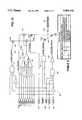
- FIG. 13is a block electrical schematic circuit diagram of the electrical circuit used to program each electrode as a constant current anode (+), a constant voltage cathode (-), or an open circuit, with a truth table of the inputs to the electrical circuit set forth in TABLE C.
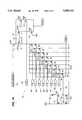
- FIG. 14is a block electrical schematic circuit diagram of a D/A converter of the electrical circuit shown in FIG. 13.
- FIG. 15is a block electrical schematic circuit diagram of circuitry for the current paths between one constant voltage cathode and two independent constant current anodes with a constant voltage pulse supplied at the cathode electrode illustrated in TABLE D.
- FIG. 16is a fragmentary view of the distal tip of a stimulating lead which can be bent and then rotated for effecting a desired placement of the electrodes on the distal tip.
- FIG. 17is a block diagram of a neural stimulator system and lead steering mechanism on which a stimulating lead is mounted.
- FIG. 18is a longitudinal perspective view of the stimulating lead which is mounted on the steering mechanism shown in FIG. 17.
- FIG. 19is an enlarged longitudinal sectional view of the tip of the steering mechanism shown in FIG. 17.
- FIG. 20is an enlarged longitudinal sectional view of another tip for the steering mechanism shown in FIG. 17.
- FIG. 21is an enlarged longitudinal sectional view of still another tip for the steering mechanism shown in FIG. 17.
- FIG. 1there is illustrated a block diagram of a neurological electrical stimulator 10 and steerable lead 12 constructed according to the teachings of the present invention.
- the stimulator or pulse generator 10 and one or more steerable leads 12form an electric field steering assembly constructed and operated according to the teachings of the present invention.
- the stimulator 10is connected to the single tripolar lead 12 percutaneously placed within the epidural space proximal to the target vertebrate bodies 16 and is capable of electrically modulating the size and location of the stimulating field 18 (FIG. 3) for the purpose of recruiting only the target nerve tissue and exclude unwanted nerve tissue.
- FIG. 2there is illustrated a block diagram for a neurological electrical stimulator 20 and steerable lead 22, also constructed according to the teachings of the present invention.
- the stimulator 20is connected to the single tripolar lead 22 placed proximal to the target vertebrate bodies 26 through a thoracic laminectomy and is capable of electrically modulating the size and location of the stimulating field 18 (FIG. 3) for the purpose of recruiting only the target nerve tissue and exclude unwanted nerve tissue.
- FIG. 3illustrates the use of the single tripolar lead 12 or 22 and shows how the electric field 18 can be focused near a center electrode C by making the center electrode C negative and the left and right electrodes L and R positive and shows how the size of the electric field 18 can be changed by modulating the anodic currents listed in TABLE A at the positive electrodes L and R.
- FIG. 4illustrates how a single tripolar lead 12 or 22 can be used to focus the electric field 18 near the left electrode L by programming it to a higher current than the other two electrodes C and R and how the single tripolar electrode 12 or 22 can be used to focus the electric field 18 near the right electrode R by programming it to a higher current than the other two electrodes C and L and, further how the lead 12 or 22 can be used to control the size of the electric field by modulating the anodic current of the two higher current electrodes L and R with the currents listed in TABLE B.
- FIG. 5illustrates the use of a dual channel stimulator 30 with anodic current control connected to two percutaneous-epidural leads 32 and 34.
- Each lead 32, 34is placed within the epidural space at either side of the midline proximal to the target vertebrate bodies 36.
- Each electrode 41-43 or 44-46 (FIG. 8) in each Lead 32 or 34can be programmed positive (anode) or negative (cathode), and the anodic current at each positive electrode 41, 43 or 44, 46 can be programmed to a value different from the other anodes.
- the size and location of the stimulating field, A, B or Ccan be modulated for the purpose of recruiting only the target nerve tissue and exclude unwanted nerve tissue.
- FIG. 6illustrates the use of a dual channel stimulator 50, with anodic current control, connected to two laminectomy leads 52, 54.
- Each lead 52, 54is placed at either side of the midline proximal to the target vertebrate bodies 56.
- Each electrode 41-46 in each leadcan be programmed positive (anode) or negative (cathode), and the anodic current of each positive electrode can be programmed to a value different from other anodes.
- the size and location of the stimulating field, A, B or Ccan be modulated for the purpose of recruiting only the target nerve tissue and exclude unwanted nerve tissue.
- FIG. 7illustrates a symmetrical electric field 57 generated by a prior art stimulator.
- the intentionis to recruit nerve tissue within the spinal cord corresponding to a pain area in the right side
- the resulting electric fieldpropagates uniformly around both sides of the electrodes also encircling a nerve root 58 nearby. Stimulation of the nerve root 58 results in unwanted motor responses, such as painful abdominal or chest wall stimulation.
- FIG. 8illustrates how the size and location of the electric field can be modified in the present invention to achieve a paresthesia pattern covering the pain area without stimulating the nerve root.
- Two leads 32, 34are placed at either side of the midline proximal to the target vertebrate bodies 36.
- Each electrode 41-43 or 44-46 in each lead 32,34can be programmed positive (anode) or negative (cathode), and the anodic current of each positive electrode can be programmed to a value different from other anodes.
- the size and location of the stimulating fieldcan be controlled for the purpose of recruiting only the target nerve tissue and exclude unwanted nerve tissue. In this example, only three electric fields, A, B or C, are shown but it is obvious that many more are possible.
- Electric field Ais obtained by programming electrode 42 as the cathode, electrodes 41 and 43 as anodes programmed to equal current, and electrode 45 as an anode but programmed to a current higher than the current supplied to electrodes 41 and 43.
- the resulting electric field Ais asymmetrical with a larger area at the left side of electrode 42 than at the right side, thereby missing the nerve root 58.
- Electric field Bis obtained by programming electrode 42 as the cathode, electrodes 41, 43 and 44 as the anodes but with the electrode 44 programmed, to a higher current than at the electrodes 41 and 43.
- the resulting electric field Bis asymmetrical with a larger area at the top-left side of electrode 42 than at the right-center side, thereby missing the nerve root 58.
- Electric field Cis obtained by programming electrode 42 as the cathode, electrodes 41, 43 and 46 as the anodes but with the electrode 46 programmed to a current higher than at electrodes 41 and 43.
- the resulting electric field Cis asymmetrical with a larger area at the bottom-left side of the electrode 42 than at the right-center side, thereby missing the nerve root 58.
- FIG. 9is a cross-sectional view of the electric field that forms between the electrode 42 and the electrodes 44/45/46, illustrating the pulling effect of the higher-current anodes 44/45/46 (away from the nerve root 58).
- FIG. 10illustrates the use of a tri-channel stimulator 60 with anodic current control connected to three percutaneous-epidural leads 61-63.
- One lead 62is placed within the epidural space at the midline proximal to the target vertebrate bodies 36, and the other two leads 61, 63 are placed at either side of the midline.
- Each electrode 71-79 in the leads 61-63can be programmed positive (anode) or negative (cathode), and the anodic current at each positive electrode can be programmed to a value different from the other electrode, which electrode(s) serve as the cathode.
- the size and location of the stimulating fieldcan be modulated for the purpose of recruiting only the target nerve tissue and exclude unwanted nerve tissue.
- FIG. 11illustrates the use of a tri-channel stimulator 80 with anodic current control connected to three laminectomy leads 81-83.
- One lead 82is placed at the midline proximal to the target vertebrate bodies, and the other two leads 81, 83 are placed at either side of the midline.
- Each electrode 71-79 in each lead 81-83can be programmed positive (anode) or negative (cathode), and the anodic current at each positive electrode can be programmed to a value different from other anodes.
- the size and location of the stimulating fieldcan be modulated for the purpose of recruiting only the target nerve tissue and exclude unwanted nerve tissue.
- FIG. 12illustrates how the size and location of the electric field can be modified by the neural stimulating system of the present invention to achieve a paresthesia pattern covering the pain area without recruiting unwanted nerve tissue.
- One lead 62is placed at the midline proximal to the target vertebrate bodies, and the other two leads 61, 63 are placed at either side of the midline.
- Each electrode 71-79 in each lead 61-63can be programmed positive (anode) or negative (cathode), and the anodic current of each positive electrode can be programmed to a value different from the other anodes.
- the size and location of the stimulating field, A, B or Ccan be modulated for the purpose of recruiting only the target nerve tissue and exclude unwanted nerve tissue.
- the stimulating field, A, B or Ccan be modulated for the purpose of recruiting only the target nerve tissue and exclude unwanted nerve tissue.
- only three electric fieldsare shown but it is obvious that many more are possible.
- Electric field Ais obtained by programming electrode 75 as the cathode, and the electrodes 72 and 78 as anodes. The resulting electric field is contained within the two anodes (away from nerve root 58), with the size of the electric fields at the left and right sides determined by the anodic current programmed at the electrodes 72 and 78.
- Electric field Bis obtained by programming the electrodes 74, 75 and 76 as cathodes and the electrodes 72 and 78 as anodes. The resulting electric field is contained within the two anodes (away from nerve root 58). The size of the electric fields at the left and right sides is determined by the anodic current programmed at the electrodes 72 and 78.
- Electric field Cis obtained by programming electrode 75 as the cathode, and the electrodes 73, 72, 71, 77, 78 and 79 as anodes. The resulting electric field is contained within the anodes (away from nerve root 58). The size of the electric fields at the left and right sides is determined by the anodic current programmed at the electrodes 73, 72, 71, 77, 78 and 79.
- FIG. 13illustrates one electrical circuit 80 used in the present invention to program each electrode as a constant current anode (+), a constant voltage cathode (-), or open circuit.
- an electrode 85When an electrode 85 is programmed as an anode, it sources a constant current equal to a programmed value in milliamperes.
- the electrode 85When the electrode 85 is programmed as a cathode, it sources a constant negative voltage during each stimulus pulse.
- the electrode 85is programmed off, it becomes a high impedance, exceeding 1,000,000 Ohms (practically an open circuit).
- the logic state of inputs 86 and 88determine if the electrode 85 is to be a cathode (-), an anode (+) or open circuit.
- input 86is set to a logic 0 and input 88 is set to a logic 1.
- a NAND 92will switch on a transistor 94 which will enable a D/A converter 96 to regulate current sources 98/100 to deliver the milliampere value represented by inputs 102 and 104.
- input 88is a logic 1
- a NAND 106is disabled keeping a transistor 108 off.
- the electrode 85As a cathode (-), input 86 is set to a logic one and input 88 is set to logic zero, disabling NAND 92 which makes a NAND output line 110 a logic 0 and turns off transistor 94 (the path from the electrode 85 to Vdd is blocked). However, the NAND 106 is enabled making a NAND output line 112 a logic 1 for the duration that input 90 is a logic 1, turning on transistor 108 which connects electrode 85 to Vss. After the stimulus pulse, line 86 switches to a logic 1 for a period controlled by a microcontroller or external logic, enabling a NAND 114 to turn on a transistor 116, discharge a coupling capacitor 118 and depolarizing the electrode 85.
- both inputs 86 and 88must be set to the same logic level (either one or zero) to disable both NANDS 106 and 92 so that both transistors 94 and 108 are turned off at all times, disconnecting any path between the electrode 85 and Vdd or Vss.
- FIG. 14illustrates the electrical circuit configuration of the D/A converter 96 used to regulate the anodic current.
- This circuitis better suited for implantation in a custom integrated circuit where all transistors can be closely matched.
- Transistors N16, N17, P7 and P8form a feedback loop which tends to oppose any change in the current flowing through the resistor R1 (current trim resistor) as the supply voltage changes, thus maintaining a constant current.
- Line 120provides the bias voltage to the gates of transistors N1, N2, N3, N4, N5, N6, N7 and N8 which mirror a multiple of the current flowing through transistor N18 by virtue of having binary weighted channel width/length.
- transistor N1is an X1 mirror while transistor N8 is a X128 mirror, therefore the current flowing through transistor N1 equals the current flowing through transistor N18, but the current flowing through transistor N8 is 128 times that of the current flowing through the transistor N18.
- Line 122is a "current summation point" where all the currents are joined at the drain D of the transistor P2.
- Inputs 102control which of the current multiples will pass up to the line 122 by switching on a combination of transistors N9, N10, N11, N12, N13, N14, N15 or N16 equivalent to the binary value applied to the inputs 102. This will allow current to flow through the transistors P1, P2 and into the selected combination of transistors N1 through N8, setting up a current mirror between transistors P2, P3 and P4. If input line 104 is a logic one this will switch off transistor P5, resulting in an anodic current at the electrode 85 equal to 20 times the current at transistor P2.
- the electrical circuitry of the present inventionis capable of programming the anodic constant current at the electrode 85 in 512 equal steps.
- FIG. 15illustrates the stimulation current paths between one constant voltage cathode and two independent constant current anodes.
- input line 112switches to a logic 1 turning on the transistor 108 which connects a cathode 124 to the negative supply VSS.
- inputs 110 and 126will switch to a logic 0 allowing independent current sources 128 and 130 to source anodic currents I1 and I2 to anodes 132 and 134, respectively.
- each anodecan be programmed to a different current value, allowing the electric field to be stronger at the higher current anode than at the lower one, thus providing means for: 1) electronically steering the electric field towards the target nerve, 2) maintaining the electric field focused at the target nerve even when changes in electrode impedances 136 and 138 occur, by automatically changing the positive voltage at anodes 132 and 134 as required in order to maintain currents Ii and I2 constant, thereby preserving for the duration of the therapy, the original electric field found to be effective at implant time.
- a constant voltage pulse at the cathode electrode 124is shown in TABLE D.
- FIG. 16illustrates a stimulating lead 140 having a tip 142 which can be deflected and rotated.
- FIG. 17is a block diagram of a lead steering assembly 144 and associated components of the electric field steering assembly of the present invention.
- the electric field steering assemblyincludes an external pulse generator 145 or an implantable pulse generator 146, a coupling lead 147 and the lead steering assembly 144.
- the lead steering assembly 144includes a steering mechanism 148 which is used to maneuver a mandrel or stylet 149 mounting at its distal end 150, the distal end 142 of the stimulating lead 140 (FIG. 17) around anatomical obstacles within the epidural space and into a position adjacent to the dura for the purpose of recruiting only the target nerve tissue and exclude unwanted nerve tissue.
- the construction of the stimulating lead 140is shown in FIG. 18.
- the construction of the flexible tip 150 of the steering assembly 144is shown in cross section in FIG. 19.
- the function of the lead 140 and the lead tip 142 shown in FIG. 19is to carry the electrical stimuli from the pulse generator 145 or 146 to the target tissue.
- Such leads 140are usually constructed of extruded tubular insulator material containing one or more electrodes 151-154 (FIG. 19).
- the leadIn order to improve pushability during placement, the lead contains a lumen (inside diameter) where the stylet 149 (FIG. 17) is introduced during placement. Introduction of the stylet 149 provides additional rigidity to the lead 140 during placement of the lead 140.
- the lumen inside the lead 140is utilized to introduce the stylet 149 into a lead body 160 which has a proximal end 161 adapted to be connected to the self contained steering mechanism 148.
- the lead body 160has a deflecting soft tip 142 as shown in FIG. 18.
- the steering mechanism 148includes a steering assembly handle 162 and a slide 164 mounted on the steering assembly handle 162 which is used to pull or push a wire 158 to deflect or steer the distal tip 150 mounting the lead's soft tip 142 to facilitate maneuvering and advancing the lead 140 within the spinal column epidural space.
- the slide 164 and handle 162have cooperating detents and dimples or other locking mechanism for releasably locking the slide 164 in one of several longitudinal positions on the handle 162.
- the steering assembly handle 162is equipped with electrical contacts 171-174 which allow proximal electrodes 181-184 on the proximal end 161 of the lead body 160 (FIG. 19) to be mechanically and electrically connected to the contacts 171-174 and to extend that connection to an adapter 186 (FIG. 17) which in turn can be connected to the pulse generator 145 or 146.
- the steering assembly 144is a self contained reusable or disposable steering system aimed at facilitating the introduction, advancement and placement procedure for spinal leads.
- the systemworks best when used in a lead containing a soft distal tip 142 so as to allow effective tip deflection and achieve a higher level of maneuverability within the epidural space.
- the physiciancan either remove the steering assembly 144 from the lead or crimp-cut the wire 158 and the proximal end of a NITINOL microtube 188 (FIG. 17) of a NITINOL microtube stylet assembly 149 including the wire 158 and the microtube 188 if a permanent deflection to anchor the leads electrode system is desired. If the latter approach is selected, the deflected lead can be removed from the handle 162 by retracting contacts 171-174 after crimping-cutting the steerable NITINOL microtube stylet assembly 149.
- a distal deflection of a flat tip 192 received within a coiled, easily bendable, soft wire segment 194 at the distal end 150 of the stylet 149facilitates deflection in one direction and a 360° deflecting orientation can be achieved by rotating the steering system handle 162.
- the flexible tip 150 of the steering assembly 144can be made without the coil wire 194 shown in FIG. 17 and instead a distal end portion 200 of the NITINOL tubing 188 can be ground down to provide a flexible distal end portion 200.
- a cone shaped tip member 202is eccentrically attached to an end 204 of the pull wire 158, as shown.
- the NITINOL tubing 188is caused to bend in the reduced-in-diameter end portion 200 when the pull wire 158 is pulled toward the handle 162.
- FIG. 21there is illustrated still another way of constructing the flexible tip of 150 of the steering assembly.
- the construction of the NITINOL tubing 188 in the distal end portion 200 thereofis substantially the same as that shown in FIG. 20.
- the embodiment shown in FIG. 20has a flat tip member 208, similar to the tip member 192 shown in FIG. 19 and a distal end 210 of the wire 158 is fixed to a distal end of the flat tip member 208.
- pulling of the pull wire 158will cause the flat tip member 208 to move to one side so as to cause the reduced-in-diameter end portion 200 of the NITINOL tube 188 to bend.
Landscapes
- Health & Medical Sciences (AREA)
- Life Sciences & Earth Sciences (AREA)
- General Health & Medical Sciences (AREA)
- Neurosurgery (AREA)
- Engineering & Computer Science (AREA)
- Biomedical Technology (AREA)
- Nuclear Medicine, Radiotherapy & Molecular Imaging (AREA)
- Neurology (AREA)
- Radiology & Medical Imaging (AREA)
- Animal Behavior & Ethology (AREA)
- Veterinary Medicine (AREA)
- Public Health (AREA)
- Pain & Pain Management (AREA)
- Orthopedic Medicine & Surgery (AREA)
- Cardiology (AREA)
- Heart & Thoracic Surgery (AREA)
- Electrotherapy Devices (AREA)
Abstract
Description
Claims (25)
Priority Applications (1)
| Application Number | Priority Date | Filing Date | Title |
|---|---|---|---|
| US08/814,917US5895416A (en) | 1997-03-12 | 1997-03-12 | Method and apparatus for controlling and steering an electric field |
Applications Claiming Priority (1)
| Application Number | Priority Date | Filing Date | Title |
|---|---|---|---|
| US08/814,917US5895416A (en) | 1997-03-12 | 1997-03-12 | Method and apparatus for controlling and steering an electric field |
Publications (1)
| Publication Number | Publication Date |
|---|---|
| US5895416Atrue US5895416A (en) | 1999-04-20 |
Family
ID=25216346
Family Applications (1)
| Application Number | Title | Priority Date | Filing Date |
|---|---|---|---|
| US08/814,917Expired - LifetimeUS5895416A (en) | 1997-03-12 | 1997-03-12 | Method and apparatus for controlling and steering an electric field |
Country Status (1)
| Country | Link |
|---|---|
| US (1) | US5895416A (en) |
Cited By (233)
| Publication number | Priority date | Publication date | Assignee | Title |
|---|---|---|---|---|
| US6110233A (en)* | 1998-05-11 | 2000-08-29 | Cardiac Pacemakers, Inc. | Wound multi-anode electrolytic capacitor with offset anodes |
| US6132390A (en)* | 1996-02-28 | 2000-10-17 | Eupalamus Llc | Handle for manipulation of a stylet used for deflecting a tip of a lead or catheter |
| FR2796293A1 (en)* | 1999-07-15 | 2001-01-19 | Medtronic Inc | SYSTEM FOR PRODUCING MEDICAL ELECTRICAL STIMULATION |
| US6187028B1 (en) | 1998-04-23 | 2001-02-13 | Intermedics Inc. | Capacitors having metallized film with tapered thickness |
| US6192279B1 (en)* | 1999-02-23 | 2001-02-20 | Medtronic, Inc. | Non-invasively maneuverable lead system |
| US6249423B1 (en) | 1998-04-21 | 2001-06-19 | Cardiac Pacemakers, Inc. | Electrolytic capacitor and multi-anodic attachment |
| WO2001043818A1 (en) | 1999-12-17 | 2001-06-21 | Advanced Bionics Corporation | Magnitude programming for implantable electrical stimulator |
| US6275729B1 (en) | 1998-10-02 | 2001-08-14 | Cardiac Pacemakers, Inc. | Smaller electrolytic capacitors for implantable defibrillators |
| WO2001058519A1 (en)* | 2000-02-08 | 2001-08-16 | Medtronic, Inc. | Implantable stimulation lead |
| WO2002009808A1 (en)* | 2000-07-26 | 2002-02-07 | Advanced Bionics Corporation | Rechargeable spinal cord stimulator system |
| US6385490B1 (en) | 1999-12-16 | 2002-05-07 | Cardiac Pacemakers, Inc. | Capacitors with recessed rivets allow smaller implantable defibrillators |
| US6421226B1 (en) | 1998-10-02 | 2002-07-16 | Cardiac Pacemakes, Inc. | High-energy capacitors for implantable defibrillators |
| US6426864B1 (en) | 2000-06-29 | 2002-07-30 | Cardiac Pacemakers, Inc. | High energy capacitors for implantable defibrillators |
| US20020107551A1 (en)* | 2000-12-26 | 2002-08-08 | Stahmann Jeffrey E. | Pacing and sensing vectors |
| EP1181949A3 (en)* | 2000-08-17 | 2002-09-18 | William N. Borkan | Multichannel stimulator electronics |
| US20020183817A1 (en)* | 2000-12-07 | 2002-12-05 | Paul Van Venrooij | Directional brain stimulation and recording leads |
| WO2003006106A2 (en) | 2001-07-12 | 2003-01-23 | Bmr Research & Development Limited | Apparatus for electrical stimulation |
| US20030018370A1 (en)* | 1996-04-04 | 2003-01-23 | Medtronic, Inc. | Technique for adjusting the locus of excitation of electrically excitable tissue |
| US6516227B1 (en) | 1999-07-27 | 2003-02-04 | Advanced Bionics Corporation | Rechargeable spinal cord stimulator system |
| EP1300175A2 (en) | 2001-10-03 | 2003-04-09 | Pacesetter, Inc. | XY Selectable lead assembly |
| US20030078633A1 (en)* | 2001-09-28 | 2003-04-24 | Firlik Andrew D. | Methods and implantable apparatus for electrical therapy |
| US20030083698A1 (en)* | 2001-11-01 | 2003-05-01 | Whitehurst Todd K. | Thrombolysis and chronic anticoagulation therapy |
| US20030153959A1 (en)* | 2002-02-12 | 2003-08-14 | Thacker James R. | Neural stimulation system providing auto adjustment of stimulus output as a function of sensed coupling efficiency |
| US20030163172A1 (en)* | 2000-08-21 | 2003-08-28 | John Parker | Power efficient electrical stimulation |
| US20030204223A1 (en)* | 2002-04-26 | 2003-10-30 | Medtronic, Inc. | Independent therapy programs in an implantable medical device |
| US20030204221A1 (en)* | 2002-04-26 | 2003-10-30 | Medtronic, Inc. | Wave shaping for an implantable medical device |
| US20030204226A1 (en)* | 2002-04-26 | 2003-10-30 | Medtronic, Inc. | Automatic waveform output adjustment for an implantable medical device |
| US20030204224A1 (en)* | 2002-04-26 | 2003-10-30 | Medtronic, Inc. | Programmable waveform pulses for an implantable medical device |
| US20030204225A1 (en)* | 2002-04-26 | 2003-10-30 | Medtronic, Inc. | Detection of possible failure of capacitive elements in an implantable medical device |
| US20030204222A1 (en)* | 2002-04-26 | 2003-10-30 | Medtronic, Inc. | Recharge delay for an implantable medical device |
| US20030208236A1 (en)* | 2002-05-06 | 2003-11-06 | Cardiac Pacemakers, Inc. | System and method for providing temporary stimulation therapy to optimize chronic electrical performance for electrodes used in conjunction with a cardiac rhythm management system |
| US20030208244A1 (en)* | 2002-04-26 | 2003-11-06 | Medtronic, Inc. | Voltage/current regulator improvements for an implantable medical device |
| US20030236557A1 (en)* | 2002-06-20 | 2003-12-25 | Whitehurst Todd K. | Cavernous nerve stimulation via unidirectional propagation of action potentials |
| US20030236558A1 (en)* | 2002-06-20 | 2003-12-25 | Whitehurst Todd K. | Vagus nerve stimulation via unidirectional propagation of action potentials |
| WO2004000416A1 (en)* | 2002-06-20 | 2003-12-31 | Advanced Bionics Corporation | Implantable microstimulators for unidirectional propagation of action potentials |
| US20040015205A1 (en)* | 2002-06-20 | 2004-01-22 | Whitehurst Todd K. | Implantable microstimulators with programmable multielectrode configuration and uses thereof |
| US20040034394A1 (en)* | 1999-01-07 | 2004-02-19 | Woods Carla Mann | Implantable generator having current steering means |
| US6704603B1 (en) | 2000-05-16 | 2004-03-09 | Lockheed Martin Corporation | Adaptive stimulator for relief of symptoms of neurological disorders |
| US20040064024A1 (en)* | 2002-09-30 | 2004-04-01 | Sommer John L. | Cardiac vein lead and guide catheter |
| US20040088025A1 (en)* | 2002-10-24 | 2004-05-06 | Lockheed Martin Corporation | Systems and methods for treating movement disorders |
| US20040098063A1 (en)* | 2002-11-15 | 2004-05-20 | Medtronic, Inc. | Human-implantable-neurostimulator user interface having multiple levels of abstraction |
| US6754539B1 (en)* | 2000-08-10 | 2004-06-22 | Advanced Neuromodulation Systems, Inc. | Spinal cord stimulation lead with an anode guard |
| US20040147978A1 (en)* | 2002-12-12 | 2004-07-29 | Bernhard Axel L. | Electro stimulation treatment apparatus and method |
| US6788976B2 (en) | 2001-11-02 | 2004-09-07 | Lockheed Martin Corporation | Movement timing simulator |
| US20040230236A1 (en)* | 2001-11-29 | 2004-11-18 | Medtronic, Inc. | Papillary muscle stimulation |
| US20040230283A1 (en)* | 2001-11-29 | 2004-11-18 | Medtronic, Inc. | Trans-septal pacing method and apparatus |
| US20050015130A1 (en)* | 2001-02-28 | 2005-01-20 | Gill Steven Streatfield | Brain electrode |
| US20050070982A1 (en)* | 2003-09-30 | 2005-03-31 | Heruth Kenneth T. | Field steerable electrical stimulation paddle, lead system, and medical device incorporating the same |
| US20050085884A1 (en)* | 2003-10-20 | 2005-04-21 | O'brien Robert C. | Connection for a coiled lead to an electrical contact for an implantable medical device |
| US6909918B2 (en)* | 2001-10-10 | 2005-06-21 | Medtronic, Inc. | Implantable percutaneous stimulation lead with lead carrier |
| US20050192648A1 (en)* | 2000-08-21 | 2005-09-01 | Cochlear Limited | Compressed neural coding |
| US20050209655A1 (en)* | 2002-02-04 | 2005-09-22 | Kerry Bradley | Method for optimizing search for spinal cord stimulation parameter settings |
| US20050209652A1 (en)* | 2001-04-26 | 2005-09-22 | Whitehurst Todd K | Methods and systems for electrical and/or drug stimulation as a therapy for erectile dysfunction |
| US20050209667A1 (en)* | 2001-08-10 | 2005-09-22 | Advanced Neuromodulation Systems, Inc., A Texas Corporation | Stimulation/sensing lead adapted for percutaneous insertion |
| US20050222641A1 (en)* | 2000-04-05 | 2005-10-06 | Pless Benjamin D | Neurostimulator involving stimulation strategies and process for using it |
| US20050240229A1 (en)* | 2001-04-26 | 2005-10-27 | Whitehurst Tood K | Methods and systems for stimulation as a therapy for erectile dysfunction |
| US20050246003A1 (en)* | 2004-04-28 | 2005-11-03 | Advanced Neuromodulation Systems, Inc. | Stimulation lead having pairs of stimulating electrodes spaced at different distances for providing electrical stimulation to different nerve tissues |
| US20050251212A1 (en)* | 2000-09-27 | 2005-11-10 | Cvrx, Inc. | Stimulus regimens for cardiovascular reflex control |
| US20060074456A1 (en)* | 2004-09-27 | 2006-04-06 | Advanced Neuromodulation Systems, Inc. | Method of using spinal cord stimulation to treat gastrointestinal and/or eating disorders or conditions |
| US20060089561A1 (en)* | 2002-09-04 | 2006-04-27 | Eder Helmut C | Method and apparatus for measurement of evoked neural response |
| WO2006060705A1 (en)* | 2004-12-03 | 2006-06-08 | Medtronic, Inc. | Subcutaneous implantable cardioverter/defibrillator |
| US20060122654A1 (en)* | 2001-12-04 | 2006-06-08 | Kerry Bradley | Apparatus and method for determining the relative position and orientation of neurostimulation leads |
| US20060122678A1 (en)* | 2004-10-21 | 2006-06-08 | Medtronic, Inc. | Transverse tripole neurostimulation methods, kits and systems |
| US20060161235A1 (en)* | 2005-01-19 | 2006-07-20 | Medtronic, Inc. | Multiple lead stimulation system and method |
| US20060161236A1 (en)* | 2005-01-19 | 2006-07-20 | Medtronic, Inc. | Apparatus for multiple site stimulation |
| US20060167525A1 (en)* | 2005-01-19 | 2006-07-27 | Medtronic, Inc. | Method of stimulating multiple sites |
| US20060173262A1 (en)* | 2005-01-31 | 2006-08-03 | Medtronic, Inc. | Medical lead with segmented electrode |
| US20060224187A1 (en)* | 2005-04-01 | 2006-10-05 | Kerry Bradley | Apparatus and methods for detecting position and migration of neurostimulation leads |
| US20060229688A1 (en)* | 2005-04-08 | 2006-10-12 | Mcclure Kelly H | Controlling stimulation parameters of implanted tissue stimulators |
| US20060235490A1 (en)* | 2000-08-21 | 2006-10-19 | Cochlear Limited | Determining stimulation signals for neural stimulation |
| US20060235332A1 (en)* | 2002-06-26 | 2006-10-19 | Smoorenburg Guido F | Parametric fitting of a cochlear implant |
| US20060253182A1 (en)* | 2004-10-21 | 2006-11-09 | Medtronic, Inc. | Transverse Tripole Neurostimulation Lead, System and Method |
| US20070021792A1 (en)* | 2000-09-27 | 2007-01-25 | Cvrx, Inc. | Baroreflex Modulation Based On Monitored Cardiovascular Parameter |
| US20070049988A1 (en)* | 2005-03-14 | 2007-03-01 | Rafael Carbunaru | Optimal electrode contact polarity configurations for implantable stimulation systems |
| US20070073354A1 (en)* | 2005-09-26 | 2007-03-29 | Knudson Mark B | Neural blocking therapy |
| US20070112395A1 (en)* | 2005-10-31 | 2007-05-17 | Cochlear Limited | Automatic Measurement Of Neural Response Concurrent With Psychophysics Measurement Of Stimulating Device Recipient |
| US20070123938A1 (en)* | 2005-11-30 | 2007-05-31 | Haller Matthew I | Magnetically coupled microstimulators |
| US7239920B1 (en) | 2002-02-12 | 2007-07-03 | Advanced Bionics Corporation | Neural stimulation system providing auto adjustment of stimulus output as a function of sensed pressure changes |
| US20070156207A1 (en)* | 2006-01-04 | 2007-07-05 | Sridhar Kothandaraman | Expanding single channel stimulator capability on multi-area stimulation programs |
| US20070168008A1 (en)* | 2004-10-21 | 2007-07-19 | Medtronic, Inc. | Implantable Medical Electrical Leads, Kits, Systems and Methods of Use Thereof |
| US20070179579A1 (en)* | 2006-01-26 | 2007-08-02 | Feler Claudio A | Method of neurostimulation of distinct neural structures using single paddle lead to treat multiple pain locations and multi-column, multi-row paddle lead for such neurostimulation |
| US20070203543A1 (en)* | 2006-02-24 | 2007-08-30 | Medtronic, Inc. | Stimulation templates for configuring stimulation therapy |
| US20070203538A1 (en)* | 2006-02-24 | 2007-08-30 | Medtronic, Inc. | User interface with an atlas for configuring stimulation therapy |
| US20070203545A1 (en)* | 2006-02-24 | 2007-08-30 | Medtronic, Inc. | User interface with 3D environment for configuring stimulation therapy |
| US20070203544A1 (en)* | 2006-02-24 | 2007-08-30 | Medtronic, Inc. | Programming interface with a concentric axial view of a stimulation lead with complex electrode array geometry |
| US20070203541A1 (en)* | 2006-02-24 | 2007-08-30 | Medtronic, Inc | Programming interface with a cross-sectional view of a stimulation lead with complex electrode array geometry |
| US20070203546A1 (en)* | 2006-02-24 | 2007-08-30 | Medtronic, Inc. | Electrical and activation field models for configuring stimulation therapy |
| US20070203537A1 (en)* | 2006-02-24 | 2007-08-30 | Medtronic, Inc. | Programming interface with an unwrapped 2D view of a stimulation lead with complex electrode array geometry |
| US20070203542A1 (en)* | 2006-02-24 | 2007-08-30 | Medtronic, Inc. | Stimulation templates for programming a stimulation lead with complex electrode array geometry |
| US20070203539A1 (en)* | 2006-02-24 | 2007-08-30 | Medtronic, Inc. | User interface with 2D views for configuring stimulation therapy |
| US20070203540A1 (en)* | 2006-02-24 | 2007-08-30 | Medtronic, Inc. | Electrical and activation field models for programming a stimulation lead with complex electrode array geometry |
| US20070225765A1 (en)* | 2006-03-22 | 2007-09-27 | Medtronic, Inc. | Technique for adjusting the locus of excitation of electrically excitable tissue with paired pulses |
| US20070225767A1 (en)* | 2001-04-18 | 2007-09-27 | Cochlear Limited | Minimization of electrical stimulus artifact during measurement of evoked neural response |
| US20070255344A1 (en)* | 2006-04-21 | 2007-11-01 | Cochlear Limited | Determining operating parameters for a stimulating medical device |
| US20080004674A1 (en)* | 2006-06-30 | 2008-01-03 | Medtronic, Inc. | Selecting electrode combinations for stimulation therapy |
| US7317948B1 (en) | 2002-02-12 | 2008-01-08 | Boston Scientific Scimed, Inc. | Neural stimulation system providing auto adjustment of stimulus output as a function of sensed impedance |
| US20080058876A1 (en)* | 2006-09-06 | 2008-03-06 | Giancarlo Barolat | Implantable reel for coiling an implantable elongated member |
| US20080061630A1 (en)* | 2004-09-03 | 2008-03-13 | Inria Institut National De Recherche En Informatique Et En Automatique | Device for Distributing Power Between Cathodes of a Multipolar Electrode, in Particular of an Implant |
| US20080065002A1 (en)* | 2006-09-07 | 2008-03-13 | Neurosystec Corporation | Catheter for Localized Drug Delivery and/or Electrical Stimulation |
| US20080071325A1 (en)* | 2002-02-04 | 2008-03-20 | Advanced Bionics Corporation | Method for optimizing search for spinal cord stimulation parameter setting |
| WO2008038208A2 (en) | 2006-09-26 | 2008-04-03 | Koninklijke Philips Electronics, N.V. | Tissue stimulation method and apparatus |
| US7363079B1 (en) | 2002-09-26 | 2008-04-22 | Boston Scientific Neuromodulation Corporation | Power qualifier for electrical stimulation configurations |
| US20080152694A1 (en)* | 2006-07-20 | 2008-06-26 | Neurosystec Corporation | Devices, Systems and Methods for Ophthalmic Drug Delivery |
| US20080171923A1 (en)* | 2000-09-27 | 2008-07-17 | Cvrx, Inc. | Assessing autonomic activity using baroreflex analysis |
| US20080177350A1 (en)* | 2000-09-27 | 2008-07-24 | Cvrx, Inc. | Expandable Stimulation Electrode with Integrated Pressure Sensor and Methods Related Thereto |
| US20080183224A1 (en)* | 2007-01-25 | 2008-07-31 | Giancarlo Barolat | Electrode paddle for neurostimulation |
| US20080188909A1 (en)* | 2007-02-01 | 2008-08-07 | Boston Scientific Neuromodulation Corporation | Neurostimulation system and method for measuring patient activity |
| US20080208288A1 (en)* | 2003-10-24 | 2008-08-28 | Lockheed Martin Corporation | Systems and methods for treating movement disorders |
| US20080215119A1 (en)* | 1999-01-07 | 2008-09-04 | Boston Scientific Neuromodulation Corporation | System and method for displaying stimulation field generated by electrode array |
| US7426414B1 (en) | 2005-03-14 | 2008-09-16 | Advanced Bionics, Llc | Sound processing and stimulation systems and methods for use with cochlear implant devices |
| US7463927B1 (en) | 2004-09-02 | 2008-12-09 | Intelligent Neurostimulation Microsystems, Llc | Self-adaptive system for the automatic detection of discomfort and the automatic generation of SCS therapies for chronic pain control |
| US20080319508A1 (en)* | 2004-06-15 | 2008-12-25 | Cochlear Americas | Automatic Determination of the Threshold of an Evoked Neural Response |
| US20090018619A1 (en)* | 2007-04-30 | 2009-01-15 | Medtronic, Inc. | Shifting of electrical stimulation electrode combinations among differently sized electrode arrays |
| US20090018617A1 (en)* | 2007-04-30 | 2009-01-15 | Medtronic, Inc. | Parameter-directed shifting of electrical stimulation electrode combinations |
| US7496405B1 (en) | 2005-03-14 | 2009-02-24 | Advanced Bionics, Llc | Sound processing and stimulation systems and methods for use with cochlear implant devices |
| US20090054947A1 (en)* | 2007-08-20 | 2009-02-26 | Medtronic, Inc. | Electrode configurations for directional leads |
| US7515966B1 (en) | 2005-03-14 | 2009-04-07 | Advanced Bionics, Llc | Sound processing and stimulation systems and methods for use with cochlear implant devices |
| US20090099439A1 (en)* | 2007-10-16 | 2009-04-16 | Giancarlo Barolat | Surgically implantable electrodes |
| US20090118795A1 (en)* | 2001-06-29 | 2009-05-07 | Cochlear Limited | Multi-electrode cochlear implant system with distributed electronics |
| US20090177247A1 (en)* | 2000-08-21 | 2009-07-09 | Cochlear Limited | Determining stimulation signals for neural stimulation |
| US20090208073A1 (en)* | 2004-07-07 | 2009-08-20 | The Cleveland Clinic Foundation | Brain stimulation models, systems, devices, and methods |
| US7627383B2 (en) | 2005-03-15 | 2009-12-01 | Boston Scientific Neuromodulation Corporation | Implantable stimulator |
| US20090326608A1 (en)* | 2008-06-25 | 2009-12-31 | Huynh Jeffrey C | Method of electrically stimulating tissue of a patient by shifting a locus of stimulation and system employing the same |
| US20100023070A1 (en)* | 2008-07-24 | 2010-01-28 | Boston Scientific Neuromodulation Corporation | System and method for maintaining a distribution of currents in an electrode array using independent voltage sources |
| US20100100152A1 (en)* | 2007-03-02 | 2010-04-22 | Koninklijke Philips Electronics N.V. | Electrode system for deep brain stimulation |
| US20100106219A1 (en)* | 2008-10-28 | 2010-04-29 | Medtronic, Inc. | Adaptable current regulator for delivery of current-based electrical stimulation therapy |
| US20100106231A1 (en)* | 2008-10-28 | 2010-04-29 | Medtronic, Inc. | Medical devices and methods for delivery of current-based electrical stimulation therapy |
| US20100137943A1 (en)* | 2008-12-03 | 2010-06-03 | Boston Scientific Neuromodulation Corporation | Method and apparatus for identifying middle lead in a tri-lead configuration |
| US20100180344A1 (en)* | 2009-01-10 | 2010-07-15 | Kaspersky Labs ZAO | Systems and Methods For Malware Classification |
| USD622844S1 (en)* | 2009-11-25 | 2010-08-31 | Verlin Alexander | Handheld electronic stethoscope |
| US20100228240A1 (en)* | 2007-09-28 | 2010-09-09 | Clinical Laserthermia Systems Ab | Apparatus and methods for the positioning of implantable leads |
| US7801600B1 (en) | 2005-05-26 | 2010-09-21 | Boston Scientific Neuromodulation Corporation | Controlling charge flow in the electrical stimulation of tissue |
| US7803148B2 (en) | 2006-06-09 | 2010-09-28 | Neurosystec Corporation | Flow-induced delivery from a drug mass |
| US20100249874A1 (en)* | 2000-09-27 | 2010-09-30 | Bolea Stephen L | Baroreflex therapy for disordered breathing |
| US20100305631A1 (en)* | 2001-12-04 | 2010-12-02 | Boston Scientific Neuromodulation Corporation | Apparatus and method for determining the relative position and orientation of neurostimulation leads |
| US7860570B2 (en) | 2002-06-20 | 2010-12-28 | Boston Scientific Neuromodulation Corporation | Implantable microstimulators and methods for unidirectional propagation of action potentials |
| US7865243B1 (en) | 2000-04-07 | 2011-01-04 | Boston Scientific Neuromodulation Corporation | Device and therapy for erectile dysfunction and other sexual dysfunction |
| US7877136B1 (en) | 2007-09-28 | 2011-01-25 | Boston Scientific Neuromodulation Corporation | Enhancement of neural signal transmission through damaged neural tissue via hyperpolarizing electrical stimulation current |
| US20110034964A1 (en)* | 2008-02-28 | 2011-02-10 | Yafei Bi | Integrated Circuit Implementation and Fault Control System, Device, and Method |
| US20110034970A1 (en)* | 2009-08-04 | 2011-02-10 | Boston Scientific Neuromodulation Corporation | Neurostimulation lead and system and methods of making and using |
| US20110040547A1 (en)* | 2008-04-29 | 2011-02-17 | Gerber Martin T | Therapy program modification based on therapy guidelines |
| US20110040546A1 (en)* | 2008-04-29 | 2011-02-17 | Medtronic, Inc. | Therapy program modification |
| US20110077717A1 (en)* | 2009-09-29 | 2011-03-31 | Poletto Christopher J | Steering stimulation current by employing steering current |
| US20110077579A1 (en)* | 2005-03-24 | 2011-03-31 | Harrison William V | Cochlear implant with localized fluid transport |
| US20110082530A1 (en)* | 2009-04-02 | 2011-04-07 | Mark Zdeblick | Method and Apparatus for Implantable Lead |
| US20110082521A1 (en)* | 2004-06-15 | 2011-04-07 | Andrew Botros | Automatic measurement of an evoked neural response concurrent with an indication of a psychophysics reaction |
| US20110093043A1 (en)* | 2009-10-21 | 2011-04-21 | Medtronic, Inc. | Programming techniques for stimulation with utilization of case electrode |
| US20110093042A1 (en)* | 2009-10-21 | 2011-04-21 | Medtronic, Inc. | Stimulation with utilization of case electrode |
| US20110106100A1 (en)* | 2009-10-30 | 2011-05-05 | Medtronic, Inc. | Steerable percutaneous paddle stimulation lead |
| US7949400B2 (en) | 2000-09-27 | 2011-05-24 | Cvrx, Inc. | Devices and methods for cardiovascular reflex control via coupled electrodes |
| US20110125214A1 (en)* | 2009-11-25 | 2011-05-26 | Medtronic, Inc. | Medical electrical stimulation with external simulated case electrode |
| US20110130809A1 (en)* | 2008-11-13 | 2011-06-02 | Proteus Biomedical, Inc. | Pacing and Stimulation Apparatus and Methods |
| US20110264171A1 (en)* | 2010-04-27 | 2011-10-27 | Medtronic, Inc. | Electrical stimulator with voltage mode emulation using regulated current |
| US20110313236A1 (en)* | 2008-11-21 | 2011-12-22 | Ucl Busines Plc | Method and apparatus for performing deep brain stimulation with an electric field |
| US20120209283A1 (en)* | 2008-12-08 | 2012-08-16 | Hui Zhu | Needle and lead and methods of use |
| US8255057B2 (en) | 2009-01-29 | 2012-08-28 | Nevro Corporation | Systems and methods for producing asynchronous neural responses to treat pain and/or other patient conditions |
| US8260430B2 (en) | 2010-07-01 | 2012-09-04 | Cochlear Limited | Stimulation channel selection for a stimulating medical device |
| US20120239109A1 (en)* | 2011-03-15 | 2012-09-20 | Boston Scientific Neuromodulation Corporation | Neurostimulation system for defining a generalized ideal multipole configuration |
| US20120239116A1 (en)* | 2011-03-15 | 2012-09-20 | Boston Scientific Neuromodulation Corporation | Neurostimulation system for matching ideal pole spacing with effective electrode separation |
| US8295943B2 (en) | 2007-08-20 | 2012-10-23 | Medtronic, Inc. | Implantable medical lead with biased electrode |
| US20120290046A1 (en)* | 2011-05-13 | 2012-11-15 | Ming-Dou Ker | Load-adaptive bioelectric current stimulator |
| US8326418B2 (en) | 2007-08-20 | 2012-12-04 | Medtronic, Inc. | Evaluating therapeutic stimulation electrode configurations based on physiological responses |
| US20130023963A1 (en)* | 2011-07-22 | 2013-01-24 | Lockheed Martin Corporation | Cochlear implant using optical stimulation with encoded information designed to limit heating effects |
| EP2550992A1 (en) | 2006-06-19 | 2013-01-30 | Highland Instruments, Inc. | Apparatus for stimulation of biological tissue |
| US8515540B2 (en) | 2011-02-24 | 2013-08-20 | Cochlear Limited | Feedthrough having a non-linear conductor |
| US8515545B2 (en) | 2011-04-29 | 2013-08-20 | Greatbatch Ltd. | Current steering neurostimulator device with unidirectional current sources |
| US8549015B2 (en) | 2007-05-01 | 2013-10-01 | Giancarlo Barolat | Method and system for distinguishing nociceptive pain from neuropathic pain |
| US8560080B2 (en) | 2010-06-11 | 2013-10-15 | Medtronic, Inc. | Programming techniques for controlling rate of change of electrical stimulation therapy |
| WO2013154754A1 (en)* | 2012-04-10 | 2013-10-17 | NeuroAccess Technologies | Systems, devices, and methods for distal fixation of a medical device |
| US8571667B2 (en) | 2011-07-01 | 2013-10-29 | Greatbatch Ltd. | Active current control using the enclosure of an implanted pulse generator |
| US8606359B2 (en) | 2000-09-27 | 2013-12-10 | Cvrx, Inc. | System and method for sustained baroreflex stimulation |
| US8612009B2 (en) | 2006-01-26 | 2013-12-17 | Advanced Neuromodulation Systems, Inc. | Method of neurostimulation of distinct neural structures using single paddle lead to treat multiple pain locations and multi-column, multi-row paddle lead for such neurostimulation |
| US8644919B2 (en) | 2008-11-13 | 2014-02-04 | Proteus Digital Health, Inc. | Shielded stimulation and sensing system and method |
| US8700148B2 (en) | 2004-09-02 | 2014-04-15 | Proteus Digital Health, Inc. | Methods and apparatus for tissue activation and monitoring |
| US8712549B2 (en) | 2002-12-11 | 2014-04-29 | Proteus Digital Health, Inc. | Method and system for monitoring and treating hemodynamic parameters |
| US8738154B2 (en) | 2008-11-13 | 2014-05-27 | Proteus Digital Health, Inc. | Multiplexed multi-electrode neurostimulation devices |
| US8812124B2 (en) | 2011-03-15 | 2014-08-19 | Boston Scientific Neuromodulation Corporation | Neurostimulation system and method for medio-laterally steering current using ideal multipole configurations |
| US8868196B2 (en) | 2011-03-15 | 2014-10-21 | Boston Scientific Neuromodulation Corporation | Neurostimulation system and method for rostro-caudally steering current using longitudinal ideal multipole configurations |
| US8868197B2 (en) | 2011-03-15 | 2014-10-21 | Boston Scientific Neuromodulation Corporation | Neurostimulation system for defining ideal multipole configurations at lead boundary |
| US8954165B2 (en) | 2012-01-25 | 2015-02-10 | Nevro Corporation | Lead anchors and associated systems and methods |
| US8996123B2 (en) | 2009-10-21 | 2015-03-31 | Medtronic, Inc. | Managing electrical stimulation therapy based on variable electrode combinations |
| US9061163B2 (en) | 2011-01-27 | 2015-06-23 | Medtronic, Inc. | Fault tolerant system for an implantable cardioverter defibrillator or pulse generator |
| US9101768B2 (en) | 2013-03-15 | 2015-08-11 | Globus Medical, Inc. | Spinal cord stimulator system |
| US9101767B2 (en) | 2011-05-18 | 2015-08-11 | Greatbatch Ltd. | Measuring load impedance with active stimulation pulses in an implanted pulse generator |
| US9227065B2 (en) | 2002-02-04 | 2016-01-05 | Boston Scientific Neuromodulation Corporation | Method for programming implantable device |
| US9265935B2 (en) | 2013-06-28 | 2016-02-23 | Nevro Corporation | Neurological stimulation lead anchors and associated systems and methods |
| US9308022B2 (en) | 2012-12-10 | 2016-04-12 | Nevro Corporation | Lead insertion devices and associated systems and methods |
| US9320901B2 (en) | 2010-04-28 | 2016-04-26 | Medtronic, Inc. | Stimulation with utilization of non-selected electrode |
| USD759803S1 (en) | 2014-10-28 | 2016-06-21 | Highland Instruments, Inc. | Adjustable headpiece with anatomical markers |
| US9375583B2 (en) | 2012-03-30 | 2016-06-28 | Medtronic, Inc. | Medical system lead adapter providing for customized stimulation pattern for a secondary lead |
| US9623241B2 (en) | 2006-06-19 | 2017-04-18 | Highland Instruments | Treatment methods |
| US9681820B2 (en) | 2010-10-21 | 2017-06-20 | Highland Instruments, Inc. | Systems for detecting a condition |
| JP2017523835A (en)* | 2014-07-24 | 2017-08-24 | ボストン サイエンティフィック ニューロモデュレイション コーポレイション | Enhancement of dorsal horn stimulation using multiple electric fields |
| US9789252B2 (en) | 2008-04-29 | 2017-10-17 | Medtronic, Inc. | Therapy program modification based on a therapy field model |
| US9872997B2 (en) | 2013-03-15 | 2018-01-23 | Globus Medical, Inc. | Spinal cord stimulator system |
| US9878170B2 (en) | 2013-03-15 | 2018-01-30 | Globus Medical, Inc. | Spinal cord stimulator system |
| US9887574B2 (en) | 2013-03-15 | 2018-02-06 | Globus Medical, Inc. | Spinal cord stimulator system |
| US9913976B2 (en) | 2006-06-19 | 2018-03-13 | Highland Instruments, Inc. | Systems and methods for stimulating and monitoring biological tissue |
| CN109731219A (en)* | 2018-12-30 | 2019-05-10 | 北京品驰医疗设备有限公司 | A kind of implanted scs device and method of adjustment |
| US10360511B2 (en) | 2005-11-28 | 2019-07-23 | The Cleveland Clinic Foundation | System and method to estimate region of tissue activation |
| WO2020082128A1 (en)* | 2018-10-23 | 2020-04-30 | Saluda Medical Pty Ltd | Current source for neurostimulation |
| AU2018200691B2 (en)* | 2011-03-15 | 2020-05-14 | Boston Scientific Neuromodulation Corporation | Neurostimulation system for defining a generalized ideal multipole configuration |
| US10980999B2 (en) | 2017-03-09 | 2021-04-20 | Nevro Corp. | Paddle leads and delivery tools, and associated systems and methods |
| WO2021144730A1 (en) | 2020-01-14 | 2021-07-22 | Inner Cosmos Inc. | Devices, systems and methods for cortical stimulation |
| US11110270B2 (en) | 2015-05-31 | 2021-09-07 | Closed Loop Medical Pty Ltd | Brain neurostimulator electrode fitting |
| US11172864B2 (en) | 2013-11-15 | 2021-11-16 | Closed Loop Medical Pty Ltd | Monitoring brain neural potentials |
| US11179091B2 (en) | 2016-06-24 | 2021-11-23 | Saluda Medical Pty Ltd | Neural stimulation for reduced artefact |
| US11191966B2 (en) | 2016-04-05 | 2021-12-07 | Saluda Medical Pty Ltd | Feedback control of neuromodulation |
| US20210386994A1 (en)* | 2018-11-08 | 2021-12-16 | Checkpoint Surgical, Inc. | Nerve regeneration therapy system and method |
| US11219766B2 (en) | 2014-12-11 | 2022-01-11 | Saluda Medical Pty Ltd | Method and device for feedback control of neural stimulation |
| US11273309B2 (en) | 2019-02-08 | 2022-03-15 | Boston Scientific Neuromodulation Corporation | Linking and concurrent steering of multiple pole configurations in a spinal cord stimulation system |
| US11318310B1 (en) | 2015-10-26 | 2022-05-03 | Nevro Corp. | Neuromodulation for altering autonomic functions, and associated systems and methods |
| US11324427B2 (en) | 2011-05-13 | 2022-05-10 | Saluda Medical Pty Ltd | Method and apparatus for measurement of neural response |
| US11337658B2 (en) | 2013-11-22 | 2022-05-24 | Saluda Medical Pty Ltd | Method and device for detecting a neural response in a neural measurement |
| US11389098B2 (en) | 2012-11-06 | 2022-07-19 | Saluda Medical Pty Ltd | Method and system for controlling electrical conditions of tissue |
| US11400280B2 (en) | 2016-12-22 | 2022-08-02 | Medtronic, Inc. | Deployable electrode array lead assembly for implantable electrical stimulation |
| US11413461B2 (en) | 2019-11-25 | 2022-08-16 | Medtronic, Inc. | Independent control of electrical stimulation amplitude for electrodes for delivery of electrical stimulation therapy |
| US11413460B2 (en) | 2011-05-13 | 2022-08-16 | Saluda Medical Pty Ltd | Method and apparatus for application of a neural stimulus |
| US11420045B2 (en) | 2018-03-29 | 2022-08-23 | Nevro Corp. | Leads having sidewall openings, and associated systems and methods |
| US11445958B2 (en) | 2011-05-13 | 2022-09-20 | Saluda Medical Pty Ltd | Method and apparatus for estimating neural recruitment |
| US11457849B2 (en) | 2014-05-05 | 2022-10-04 | Saluda Medical Pty Ltd | Neural measurement |
| US11467665B2 (en) | 2018-06-14 | 2022-10-11 | Meron Gribetz | Virtual user interface system and methods for use thereof |
| US11590352B2 (en) | 2019-01-29 | 2023-02-28 | Nevro Corp. | Ramped therapeutic signals for modulating inhibitory interneurons, and associated systems and methods |
| US11602627B2 (en) | 2018-03-20 | 2023-03-14 | Second Heart Assist, Inc. | Circulatory assist pump |
| US11819332B2 (en) | 2011-05-13 | 2023-11-21 | Saluda Medical Pty Ltd | Method and apparatus for measurement of neural response |
| US11938320B2 (en) | 2015-04-09 | 2024-03-26 | Saluda Medical Pty Ltd | Electrode to nerve distance estimation |
| US11944820B2 (en) | 2018-04-27 | 2024-04-02 | Saluda Medical Pty Ltd | Neurostimulation of mixed nerves |
| US12059567B1 (en)* | 2005-01-21 | 2024-08-13 | Michael Sasha John | Systems and methods for improved spinal cord stimulation |
| US12109418B2 (en) | 2020-11-25 | 2024-10-08 | Medtronic, Inc. | Segmented lead independent electrode control for sensing or adaptive stimulation |
| US12138055B2 (en) | 2014-12-11 | 2024-11-12 | Saluda Medical Pty Ltd | Implantable electrode positioning |
| US12285263B2 (en) | 2014-03-28 | 2025-04-29 | Saluda Medical Pty Ltd | Assessing neural state from action potentials |
| US12290371B2 (en) | 2019-02-07 | 2025-05-06 | Inner Cosmos Inc. | Intracalvarial BCI systems and methods for their making, implantation and use |
| US12329527B2 (en) | 2014-11-17 | 2025-06-17 | Saluda Medical Pty Ltd | Method and device for detecting a neural response in neural measurements |
Citations (11)
| Publication number | Priority date | Publication date | Assignee | Title |
|---|---|---|---|---|
| US4285347A (en)* | 1979-07-25 | 1981-08-25 | Cordis Corporation | Stabilized directional neural electrode lead |
| WO1986000234A1 (en)* | 1984-06-21 | 1986-01-16 | Medtronic, Inc. | Process and apparatus for diaphragmic stimulation |
| US4799496A (en)* | 1987-06-03 | 1989-01-24 | Lake Region Manufacturing Company, Inc. | Guide wire handle |
| WO1993020887A1 (en)* | 1992-04-20 | 1993-10-28 | Case Western Reserve University | Thin film implantable electrode and method of manufacture |
| US5336182A (en)* | 1990-02-02 | 1994-08-09 | Ep Technologies, Inc. | Catheter steering mechanism |
| US5345937A (en)* | 1991-02-15 | 1994-09-13 | Raychem Corporation | Steerable cannula |
| US5392791A (en)* | 1992-04-24 | 1995-02-28 | Siemens Elema Ab | Controllable intracardial electrode device |
| US5417719A (en)* | 1993-08-25 | 1995-05-23 | Medtronic, Inc. | Method of using a spinal cord stimulation lead |
| US5480421A (en)* | 1992-10-30 | 1996-01-02 | Medtronic, Inc. | Lead with stylet capture member |
| US5501703A (en)* | 1994-01-24 | 1996-03-26 | Medtronic, Inc. | Multichannel apparatus for epidural spinal cord stimulator |
| US5636634A (en)* | 1993-03-16 | 1997-06-10 | Ep Technologies, Inc. | Systems using guide sheaths for introducing, deploying, and stabilizing cardiac mapping and ablation probes |
- 1997
- 1997-03-12USUS08/814,917patent/US5895416A/ennot_activeExpired - Lifetime
Patent Citations (12)
| Publication number | Priority date | Publication date | Assignee | Title |
|---|---|---|---|---|
| US4285347A (en)* | 1979-07-25 | 1981-08-25 | Cordis Corporation | Stabilized directional neural electrode lead |
| WO1986000234A1 (en)* | 1984-06-21 | 1986-01-16 | Medtronic, Inc. | Process and apparatus for diaphragmic stimulation |
| US4799496A (en)* | 1987-06-03 | 1989-01-24 | Lake Region Manufacturing Company, Inc. | Guide wire handle |
| US5336182A (en)* | 1990-02-02 | 1994-08-09 | Ep Technologies, Inc. | Catheter steering mechanism |
| US5345937A (en)* | 1991-02-15 | 1994-09-13 | Raychem Corporation | Steerable cannula |
| WO1993020887A1 (en)* | 1992-04-20 | 1993-10-28 | Case Western Reserve University | Thin film implantable electrode and method of manufacture |
| US5392791A (en)* | 1992-04-24 | 1995-02-28 | Siemens Elema Ab | Controllable intracardial electrode device |
| US5480421A (en)* | 1992-10-30 | 1996-01-02 | Medtronic, Inc. | Lead with stylet capture member |
| US5636634A (en)* | 1993-03-16 | 1997-06-10 | Ep Technologies, Inc. | Systems using guide sheaths for introducing, deploying, and stabilizing cardiac mapping and ablation probes |
| US5417719A (en)* | 1993-08-25 | 1995-05-23 | Medtronic, Inc. | Method of using a spinal cord stimulation lead |
| US5501703A (en)* | 1994-01-24 | 1996-03-26 | Medtronic, Inc. | Multichannel apparatus for epidural spinal cord stimulator |
| US5643330A (en)* | 1994-01-24 | 1997-07-01 | Medtronic, Inc. | Multichannel apparatus for epidural spinal cord stimulation |
Non-Patent Citations (2)
| Title |
|---|
| IEEE Transactions On Biomedical Engineering, vol. 26, No. 8, Aug. 1989, "Orderly Stimulation Of Skeletal Muscle Motor Units With Tripolar Nerve Cuff Electrode", Baratta et al., pp. 836-843. |
| IEEE Transactions On Biomedical Engineering, vol. 26, No. 8, Aug. 1989, Orderly Stimulation Of Skeletal Muscle Motor Units With Tripolar Nerve Cuff Electrode , Baratta et al., pp. 836 843.* |
Cited By (575)
| Publication number | Priority date | Publication date | Assignee | Title |
|---|---|---|---|---|
| US6132390A (en)* | 1996-02-28 | 2000-10-17 | Eupalamus Llc | Handle for manipulation of a stylet used for deflecting a tip of a lead or catheter |
| US20030018370A1 (en)* | 1996-04-04 | 2003-01-23 | Medtronic, Inc. | Technique for adjusting the locus of excitation of electrically excitable tissue |
| US6988006B2 (en)* | 1996-04-04 | 2006-01-17 | Medtronic, Inc. | Technique for adjusting the locus of excitation of electrically excitable tissue |
| US20100137926A1 (en)* | 1996-04-04 | 2010-06-03 | Medtronic, Inc. | Technique for Adjusting the Locus of Excitation of Electrically Excitable Tissue |
| US6597564B2 (en) | 1998-04-21 | 2003-07-22 | Cardiac Pacemakers, Inc. | Electrolytic capacitor and multi-anodic attachment |
| US6881232B2 (en) | 1998-04-21 | 2005-04-19 | Cardiac Pacemakers, Inc. | Electrolytic capacitor and multi-anodic attachment |
| US6249423B1 (en) | 1998-04-21 | 2001-06-19 | Cardiac Pacemakers, Inc. | Electrolytic capacitor and multi-anodic attachment |
| US20040105212A1 (en)* | 1998-04-21 | 2004-06-03 | Cardiac Pacemakers, Inc. | Electrolytic capacitor and multi-anodic attachment |
| US6187028B1 (en) | 1998-04-23 | 2001-02-13 | Intermedics Inc. | Capacitors having metallized film with tapered thickness |
| US6514276B2 (en) | 1998-04-23 | 2003-02-04 | Intermedics, Inc. | Metallized film capacitor for use in implantable defibrillator |
| US6110233A (en)* | 1998-05-11 | 2000-08-29 | Cardiac Pacemakers, Inc. | Wound multi-anode electrolytic capacitor with offset anodes |
| US20060256505A1 (en)* | 1998-10-02 | 2006-11-16 | Cardiac Pacemakers, Inc. | High-energy capacitors for implantable defibrillators |
| US6421226B1 (en) | 1998-10-02 | 2002-07-16 | Cardiac Pacemakes, Inc. | High-energy capacitors for implantable defibrillators |
| US20090269610A1 (en)* | 1998-10-02 | 2009-10-29 | O'phelan Michael J | High-energy capacitors for implantable defibrillators |
| US20030223178A1 (en)* | 1998-10-02 | 2003-12-04 | Cardiac Pacemakers, Inc. | Smaller electrolytic capacitors for implantable defibrillators |
| US7251123B2 (en) | 1998-10-02 | 2007-07-31 | Cardiac Pacemakers, Inc. | Smaller electrolytic capacitors for implantable defibrillators |
| US20050237697A1 (en)* | 1998-10-02 | 2005-10-27 | Cardiac Pacemakers, Inc. | Smaller electrolytic capacitors for implantable defibrillators |
| US6275729B1 (en) | 1998-10-02 | 2001-08-14 | Cardiac Pacemakers, Inc. | Smaller electrolytic capacitors for implantable defibrillators |
| US6839224B2 (en) | 1998-10-02 | 2005-01-04 | Cardiac Pacemakers, Inc. | Smaller electrolytic capacitors for implantable defibrillators |
| US6556863B1 (en) | 1998-10-02 | 2003-04-29 | Cardiac Pacemakers, Inc. | High-energy capacitors for implantable defibrillators |
| US7558051B2 (en) | 1998-10-02 | 2009-07-07 | Cardiac Pacemakers, Inc. | High-energy capacitors for implantable defibrillators |
| US6535374B2 (en) | 1998-10-02 | 2003-03-18 | Cardiac Pacemakers, Inc. | Smaller electrolytic capacitors for implantable defibrillators |
| US20040039421A1 (en)* | 1998-10-02 | 2004-02-26 | Cardiac Pacemakers, Inc. | High-energy electrolytic capacitors for implantable defibrillators |
| US7043300B2 (en) | 1998-10-02 | 2006-05-09 | Cardiac Pacemakers, Inc. | High-energy electrolytic capacitors for implantable defibrillators |
| US8805524B2 (en) | 1999-01-07 | 2014-08-12 | Boston Scientific Neuromodulation Corporation | System and method for displaying stimulation field generated by electrode array |
| US8401658B2 (en) | 1999-01-07 | 2013-03-19 | Boston Scientific Neuromodulation Corporation | System and method for displaying stimulation field generated by electrode array |
| US20040034394A1 (en)* | 1999-01-07 | 2004-02-19 | Woods Carla Mann | Implantable generator having current steering means |
| US20080215119A1 (en)* | 1999-01-07 | 2008-09-04 | Boston Scientific Neuromodulation Corporation | System and method for displaying stimulation field generated by electrode array |
| US7555346B1 (en)* | 1999-01-07 | 2009-06-30 | Boston Scientific Neuromodulation Corporation | Implantable pulse generator having current steering means |
| US7930030B2 (en) | 1999-01-07 | 2011-04-19 | Boston Scientific Neuromodulation Corporation | Implantable pulse generator having current steering means |
| US8121701B2 (en) | 1999-01-07 | 2012-02-21 | Boston Scientific Neuromodulation Corporation | System and method for displaying stimulation field generated by electrode array |
| US9050473B2 (en) | 1999-01-07 | 2015-06-09 | Boston Sceintific Neuromodulation Corporation | System for normalizing amplitude programming of a tissue stimulator |
| US20110060386A1 (en)* | 1999-01-07 | 2011-03-10 | Boston Scientific Neuromodulation Corporation | System and method for displaying stimulation field generated by electrode array |
| US6909917B2 (en) | 1999-01-07 | 2005-06-21 | Advanced Bionics Corporation | Implantable generator having current steering means |
| US20080221637A1 (en)* | 1999-01-07 | 2008-09-11 | Boston Scientific Neuromodulation Corporation | Implantable pulse generator having current steering means |
| US8265762B2 (en) | 1999-01-07 | 2012-09-11 | Boston Scientific Neuromodulation Corporation | Implantable pulse generator having current steering means |
| US6192279B1 (en)* | 1999-02-23 | 2001-02-20 | Medtronic, Inc. | Non-invasively maneuverable lead system |
| FR2796293A1 (en)* | 1999-07-15 | 2001-01-19 | Medtronic Inc | SYSTEM FOR PRODUCING MEDICAL ELECTRICAL STIMULATION |
| US6895280B2 (en) | 1999-07-27 | 2005-05-17 | Advanced Bionics Corporation | Rechargeable spinal cord stimulator system |
| US6516227B1 (en) | 1999-07-27 | 2003-02-04 | Advanced Bionics Corporation | Rechargeable spinal cord stimulator system |
| US6853538B2 (en) | 1999-12-16 | 2005-02-08 | Cardiac Pacemakers, Inc. | Capacitors with recessed rivets allow smaller implantable defibrillators |
| US6385490B1 (en) | 1999-12-16 | 2002-05-07 | Cardiac Pacemakers, Inc. | Capacitors with recessed rivets allow smaller implantable defibrillators |
| WO2001043818A1 (en) | 1999-12-17 | 2001-06-21 | Advanced Bionics Corporation | Magnitude programming for implantable electrical stimulator |
| US6587724B2 (en) | 1999-12-17 | 2003-07-01 | Advanced Bionics Corporation | Magnitude programming for implantable electrical stimulator |
| EP1514576A1 (en)* | 2000-02-08 | 2005-03-16 | Medtronic, Inc. | Implantable stimulation lead |
| WO2001058519A1 (en)* | 2000-02-08 | 2001-08-16 | Medtronic, Inc. | Implantable stimulation lead |
| US20030229387A1 (en)* | 2000-02-08 | 2003-12-11 | Medtronic, Inc. | Surgical lead body |
| US6587733B1 (en) | 2000-02-08 | 2003-07-01 | Medtronic, Inc. | Percutaneous surgical lead body with directed stimulation |
| US7319904B2 (en) | 2000-02-08 | 2008-01-15 | Medtronic, Inc. | Percutaneous Surgical lead body |
| US8412333B2 (en) | 2000-04-05 | 2013-04-02 | Neuropace, Inc. | Neurostimulator involving stimulation strategies and process for using it |
| US20050222641A1 (en)* | 2000-04-05 | 2005-10-06 | Pless Benjamin D | Neurostimulator involving stimulation strategies and process for using it |
| US8326417B2 (en) | 2000-04-05 | 2012-12-04 | Neuropace, Inc. | Neurostimulator involving stimulation strategies and process for using it |
| US8073544B2 (en)* | 2000-04-05 | 2011-12-06 | Neuropace, Inc. | Neurostimulator involving stimulation strategies and process for using it |
| US20110213441A1 (en)* | 2000-04-05 | 2011-09-01 | Neuropace, Inc. | Neurostimulator involving stimulation strategies and process for using it |
| US8694106B2 (en) | 2000-04-05 | 2014-04-08 | Neuropace, Inc. | Neurostimulator involving stimulation strategies and process for using it |
| US20110213442A1 (en)* | 2000-04-05 | 2011-09-01 | Neuropace, Inc. | Neurostimulator involving stimulation strategies and process for using it |
| US7865243B1 (en) | 2000-04-07 | 2011-01-04 | Boston Scientific Neuromodulation Corporation | Device and therapy for erectile dysfunction and other sexual dysfunction |
| US7890177B1 (en) | 2000-04-07 | 2011-02-15 | Boston Scientific Neuromodulation Corporation | Device and therapy for erectile dysfunction and other sexual dysfunction |
| US6704603B1 (en) | 2000-05-16 | 2004-03-09 | Lockheed Martin Corporation | Adaptive stimulator for relief of symptoms of neurological disorders |
| US6426864B1 (en) | 2000-06-29 | 2002-07-30 | Cardiac Pacemakers, Inc. | High energy capacitors for implantable defibrillators |
| EP1518584B1 (en)* | 2000-07-26 | 2008-10-29 | Boston Scientific Neuromodulation Corporation | Stimulator system |
| WO2002009808A1 (en)* | 2000-07-26 | 2002-02-07 | Advanced Bionics Corporation | Rechargeable spinal cord stimulator system |
| US8340784B2 (en) | 2000-08-10 | 2012-12-25 | Advanced Neuromodulation Systems, Inc. | Stimulation/sensing lead adapted for percutaneous insertion |
| US6754539B1 (en)* | 2000-08-10 | 2004-06-22 | Advanced Neuromodulation Systems, Inc. | Spinal cord stimulation lead with an anode guard |
| US20090132017A1 (en)* | 2000-08-10 | 2009-05-21 | Erickson John H | Stimulation/sensing lead adapted for percutaneous insertion |
| EP1181949A3 (en)* | 2000-08-17 | 2002-09-18 | William N. Borkan | Multichannel stimulator electronics |
| US6662053B2 (en) | 2000-08-17 | 2003-12-09 | William N. Borkan | Multichannel stimulator electronics and methods |
| US20060235490A1 (en)* | 2000-08-21 | 2006-10-19 | Cochlear Limited | Determining stimulation signals for neural stimulation |
| US20030163172A1 (en)* | 2000-08-21 | 2003-08-28 | John Parker | Power efficient electrical stimulation |
| US20080051853A1 (en)* | 2000-08-21 | 2008-02-28 | Cochlear Limited | Power efficient electrical stimulation |
| US8285382B2 (en) | 2000-08-21 | 2012-10-09 | Cochlear Limited | Determining stimulation signals for neural stimulation |
| US8050770B2 (en) | 2000-08-21 | 2011-11-01 | Cochlear Limited | Power efficient electrical stimulation |
| US9008786B2 (en) | 2000-08-21 | 2015-04-14 | Cochlear Limited | Determining stimulation signals for neural stimulation |
| US7822478B2 (en) | 2000-08-21 | 2010-10-26 | Cochlear Limited | Compressed neural coding |
| US7272446B2 (en)* | 2000-08-21 | 2007-09-18 | Cochlear Limited | Power efficient electrical stimulation |
| US20050192648A1 (en)* | 2000-08-21 | 2005-09-01 | Cochlear Limited | Compressed neural coding |
| US20090177247A1 (en)* | 2000-08-21 | 2009-07-09 | Cochlear Limited | Determining stimulation signals for neural stimulation |
| US9427583B2 (en) | 2000-09-27 | 2016-08-30 | Cvrx, Inc. | Electrode structures and methods for their use in cardiovascular reflex control |
| US8086314B1 (en) | 2000-09-27 | 2011-12-27 | Cvrx, Inc. | Devices and methods for cardiovascular reflex control |
| US20070021792A1 (en)* | 2000-09-27 | 2007-01-25 | Cvrx, Inc. | Baroreflex Modulation Based On Monitored Cardiovascular Parameter |
| US8606359B2 (en) | 2000-09-27 | 2013-12-10 | Cvrx, Inc. | System and method for sustained baroreflex stimulation |
| US8880190B2 (en) | 2000-09-27 | 2014-11-04 | Cvrx, Inc. | Electrode structures and methods for their use in cardiovascular reflex control |
| US20100191303A1 (en)* | 2000-09-27 | 2010-07-29 | Cvrx, Inc. | Automatic baroreflex modulation responsive to adverse event |
| US7949400B2 (en) | 2000-09-27 | 2011-05-24 | Cvrx, Inc. | Devices and methods for cardiovascular reflex control via coupled electrodes |
| US8838246B2 (en) | 2000-09-27 | 2014-09-16 | Cvrx, Inc. | Devices and methods for cardiovascular reflex treatments |
| US8583236B2 (en) | 2000-09-27 | 2013-11-12 | Cvrx, Inc. | Devices and methods for cardiovascular reflex control |
| US20050251212A1 (en)* | 2000-09-27 | 2005-11-10 | Cvrx, Inc. | Stimulus regimens for cardiovascular reflex control |
| US20080171923A1 (en)* | 2000-09-27 | 2008-07-17 | Cvrx, Inc. | Assessing autonomic activity using baroreflex analysis |
| US9044609B2 (en) | 2000-09-27 | 2015-06-02 | Cvrx, Inc. | Electrode structures and methods for their use in cardiovascular reflex control |
| US8060206B2 (en) | 2000-09-27 | 2011-11-15 | Cvrx, Inc. | Baroreflex modulation to gradually decrease blood pressure |
| US20070021794A1 (en)* | 2000-09-27 | 2007-01-25 | Cvrx, Inc. | Baroreflex Therapy for Disordered Breathing |
| US8290595B2 (en) | 2000-09-27 | 2012-10-16 | Cvrx, Inc. | Method and apparatus for stimulation of baroreceptors in pulmonary artery |
| US20080215111A1 (en)* | 2000-09-27 | 2008-09-04 | Cvrx, Inc. | Devices and Methods for Cardiovascular Reflex Control |
| US8712531B2 (en) | 2000-09-27 | 2014-04-29 | Cvrx, Inc. | Automatic baroreflex modulation responsive to adverse event |
| US20100249874A1 (en)* | 2000-09-27 | 2010-09-30 | Bolea Stephen L | Baroreflex therapy for disordered breathing |
| US8718789B2 (en) | 2000-09-27 | 2014-05-06 | Cvrx, Inc. | Electrode structures and methods for their use in cardiovascular reflex control |
| US7840271B2 (en) | 2000-09-27 | 2010-11-23 | Cvrx, Inc. | Stimulus regimens for cardiovascular reflex control |
| US7813812B2 (en) | 2000-09-27 | 2010-10-12 | Cvrx, Inc. | Baroreflex stimulator with integrated pressure sensor |
| US20080177350A1 (en)* | 2000-09-27 | 2008-07-24 | Cvrx, Inc. | Expandable Stimulation Electrode with Integrated Pressure Sensor and Methods Related Thereto |
| US7212867B2 (en) | 2000-12-07 | 2007-05-01 | Medtronic, Inc. | Directional brain stimulation and recording leads |
| US20020183817A1 (en)* | 2000-12-07 | 2002-12-05 | Paul Van Venrooij | Directional brain stimulation and recording leads |
| US7130682B2 (en) | 2000-12-26 | 2006-10-31 | Cardiac Pacemakers, Inc. | Pacing and sensing vectors |
| US20020107551A1 (en)* | 2000-12-26 | 2002-08-08 | Stahmann Jeffrey E. | Pacing and sensing vectors |
| US20070049978A1 (en)* | 2001-02-08 | 2007-03-01 | Cardiac Pacemakers, Inc. | Pacing and sensing vectors |
| US20070055313A1 (en)* | 2001-02-08 | 2007-03-08 | Cardiac Pacemakers, Inc. | Pacing and sensing vectors |
| US9278221B2 (en) | 2001-02-08 | 2016-03-08 | Cardiac Pacemakers, Inc. | Pacing and sensing vectors |
| US7991468B2 (en) | 2001-02-08 | 2011-08-02 | Cardiac Pacemakers, Inc. | Pacing and sensing vectors |
| US8798744B2 (en) | 2001-02-08 | 2014-08-05 | Cardiac Pacemakers, Inc. | Pacing and sensing vectors |
| US7945325B2 (en) | 2001-02-08 | 2011-05-17 | Cardiac Pacemakers, Inc. | Pacing and sensing vectors |
| US20050015130A1 (en)* | 2001-02-28 | 2005-01-20 | Gill Steven Streatfield | Brain electrode |
| US8442653B2 (en) | 2001-02-28 | 2013-05-14 | Medtronic, Inc. | Brain electrode |
| US20110131808A1 (en)* | 2001-02-28 | 2011-06-09 | Medtronic, Inc. | Brain electrode |
| US20070225767A1 (en)* | 2001-04-18 | 2007-09-27 | Cochlear Limited | Minimization of electrical stimulus artifact during measurement of evoked neural response |
| US8454529B2 (en) | 2001-04-18 | 2013-06-04 | Cochlear Limited | Minimization of electrical stimulus artifact during measurement of evoked neural response |
| US20050209652A1 (en)* | 2001-04-26 | 2005-09-22 | Whitehurst Todd K | Methods and systems for electrical and/or drug stimulation as a therapy for erectile dysfunction |
| US20050240229A1 (en)* | 2001-04-26 | 2005-10-27 | Whitehurst Tood K | Methods and systems for stimulation as a therapy for erectile dysfunction |
| US7660631B2 (en) | 2001-04-26 | 2010-02-09 | Boston Scientific Neuromodulation Corporation | Methods and systems for electrical and/or drug stimulation as a therapy for erectile dysfunction |
| US20090118795A1 (en)* | 2001-06-29 | 2009-05-07 | Cochlear Limited | Multi-electrode cochlear implant system with distributed electronics |
| US8082040B2 (en) | 2001-06-29 | 2011-12-20 | Cochlear Limited | Multi-electrode cochlear implant system with distributed electronics |
| WO2003006106A3 (en)* | 2001-07-12 | 2003-05-30 | Bio Medical Res Ltd | Apparatus for electrical stimulation |
| US20030093133A1 (en)* | 2001-07-12 | 2003-05-15 | Crowe Louis Michael | Method and apparatus for electrical stimulation |
| US6944503B2 (en) | 2001-07-12 | 2005-09-13 | Bmr Research And Development Limited | Method and apparatus for electrical stimulation |
| EP2269690A1 (en) | 2001-07-12 | 2011-01-05 | BMR Research & Development Limited | Apparatus for electrical stimulation |
| GB2378903A (en)* | 2001-07-12 | 2003-02-26 | Bmr Res & Dev Ltd | Electrical tissue and nerve stimulation with spacial and temporal discrimination by switching of arrayed electrodes. |
| WO2003006106A2 (en) | 2001-07-12 | 2003-01-23 | Bmr Research & Development Limited | Apparatus for electrical stimulation |
| US20050209667A1 (en)* | 2001-08-10 | 2005-09-22 | Advanced Neuromodulation Systems, Inc., A Texas Corporation | Stimulation/sensing lead adapted for percutaneous insertion |
| US20080097540A1 (en)* | 2001-09-26 | 2008-04-24 | Cvrx, Inc. | Ecg input to implantable pulse generator using carotid sinus leads |
| US20030078633A1 (en)* | 2001-09-28 | 2003-04-24 | Firlik Andrew D. | Methods and implantable apparatus for electrical therapy |
| WO2003026736A3 (en)* | 2001-09-28 | 2003-11-06 | Vertis Neuroscience Inc | Methods and implantable apparatus for electrical therapy |
| US6687542B2 (en) | 2001-10-03 | 2004-02-03 | Pacesetter, Inc. | XY selectable lead assembly |
| EP1300175A2 (en) | 2001-10-03 | 2003-04-09 | Pacesetter, Inc. | XY Selectable lead assembly |
| US6909918B2 (en)* | 2001-10-10 | 2005-06-21 | Medtronic, Inc. | Implantable percutaneous stimulation lead with lead carrier |
| US7877137B2 (en) | 2001-11-01 | 2011-01-25 | Boston Scientific Neuromodulation Corporation | Thrombolysis and chronic anticoagulation therapy |
| US20030083698A1 (en)* | 2001-11-01 | 2003-05-01 | Whitehurst Todd K. | Thrombolysis and chronic anticoagulation therapy |
| US7308303B2 (en) | 2001-11-01 | 2007-12-11 | Advanced Bionics Corporation | Thrombolysis and chronic anticoagulation therapy |
| US20080286327A1 (en)* | 2001-11-01 | 2008-11-20 | Whitehurst Todd K | Thombolysis and chronic anticoagulation therapy |
| US6788976B2 (en) | 2001-11-02 | 2004-09-07 | Lockheed Martin Corporation | Movement timing simulator |
| US20040230283A1 (en)* | 2001-11-29 | 2004-11-18 | Medtronic, Inc. | Trans-septal pacing method and apparatus |
| US20040230236A1 (en)* | 2001-11-29 | 2004-11-18 | Medtronic, Inc. | Papillary muscle stimulation |
| US20100298841A1 (en)* | 2001-11-29 | 2010-11-25 | Medtronic, Inc. | Trans-septal pacing method and apparatus |
| US8396549B2 (en) | 2001-11-29 | 2013-03-12 | Medtronic, Inc. | Papillary muscle stimulation |
| US7684869B2 (en) | 2001-12-04 | 2010-03-23 | Boston Scientific Neuromodulation Corporation | Apparatus and method for determining the relative position and orientation of neurostimulation leads |
| US9192760B2 (en) | 2001-12-04 | 2015-11-24 | Boston Scientific Neuromodulation Corporation | Apparatus and method for determining the relative position and orientation of neurostimulation leads |
| US20060122654A1 (en)* | 2001-12-04 | 2006-06-08 | Kerry Bradley | Apparatus and method for determining the relative position and orientation of neurostimulation leads |
| US20180296828A1 (en)* | 2001-12-04 | 2018-10-18 | Boston Scientific Neuromodulation Corporation | Apparatus and method for determining the relative position and orientation of neurostimulation leads |
| US20060122653A1 (en)* | 2001-12-04 | 2006-06-08 | Kerry Bradley | Apparatus and method for determining the relative position and orientation of neurostimulation leads |
| US8682447B2 (en) | 2001-12-04 | 2014-03-25 | Boston Scientific Neuromodulation Corporation | Apparatus and method for determining the relative position and orientation of neurostimulation leads |
| US9610439B2 (en) | 2001-12-04 | 2017-04-04 | Boston Scientific Neuromodulation Corporation | Apparatus and method for determining the relative position and orientation of neurostimulation leads |
| US20100305631A1 (en)* | 2001-12-04 | 2010-12-02 | Boston Scientific Neuromodulation Corporation | Apparatus and method for determining the relative position and orientation of neurostimulation leads |
| US20210205613A1 (en)* | 2001-12-04 | 2021-07-08 | Boston Scientific Neuromodulation Corporation | Apparatus and method for determining the relative position and orientation of neurostimulation leads |
| US10022540B2 (en) | 2001-12-04 | 2018-07-17 | Boston Scientific Neuromodulation Corporation | Apparatus and method for determining the relative position and orientation of neurostimulation leads |
| US7853330B2 (en) | 2001-12-04 | 2010-12-14 | Boston Scientific Neuromodulation Corporation | Apparatus and method for determining the relative position and orientation of neurostimulation leads |
| US20050209655A1 (en)* | 2002-02-04 | 2005-09-22 | Kerry Bradley | Method for optimizing search for spinal cord stimulation parameter settings |
| US8065013B2 (en)* | 2002-02-04 | 2011-11-22 | Boston Scientific Neuromodulation Corporation | Method for optimizing search for spinal cord stimulation parameter setting |
| US7991482B2 (en) | 2002-02-04 | 2011-08-02 | Boston Scientific Neuromodulation Corporation | Method for optimizing search for spinal cord stimulation parameter setting |
| US9227065B2 (en) | 2002-02-04 | 2016-01-05 | Boston Scientific Neuromodulation Corporation | Method for programming implantable device |
| US20070265679A1 (en)* | 2002-02-04 | 2007-11-15 | Advanced Bionics Corporation | Method for optimizing search for spinal cord stimulation parameter setting |
| US7881805B2 (en) | 2002-02-04 | 2011-02-01 | Boston Scientific Neuromodulation Corporation | Method for optimizing search for spinal cord stimulation parameter settings |
| US9687653B2 (en) | 2002-02-04 | 2017-06-27 | Boston Scientific Neuromodulation Corporation | Method for programming implantabale device |
| US20080071325A1 (en)* | 2002-02-04 | 2008-03-20 | Advanced Bionics Corporation | Method for optimizing search for spinal cord stimulation parameter setting |
| US20100262209A1 (en)* | 2002-02-12 | 2010-10-14 | Boston Scientific Neuromodulation Corporation | Neural stimulation system providing auto adjustment of stimulus output as a function of sensed impedance |
| US8626312B2 (en) | 2002-02-12 | 2014-01-07 | Boston Scientific Neuromodulation Corporation | Neural stimulation system providing auto adjustment of stimulus output as a function of sensed impedance |
| US7742823B2 (en) | 2002-02-12 | 2010-06-22 | Boston Scientific Neuromodulation Corporation | Neural stimulation system providing auto adjustment of stimulus output as a function of sensed impedance |
| US8788056B2 (en) | 2002-02-12 | 2014-07-22 | Boston Scientific Neuromodulation Corporation | Neural stimulation system providing auto adjustment of stimulus output as a function of sensed impedance |
| US7239920B1 (en) | 2002-02-12 | 2007-07-03 | Advanced Bionics Corporation | Neural stimulation system providing auto adjustment of stimulus output as a function of sensed pressure changes |
| US9089706B2 (en) | 2002-02-12 | 2015-07-28 | Boston Scientific Neuromodulation Corporation | Neural stimulation system providing auto adjustment of stimulus output as a function of sensed impedance |
| US20030153959A1 (en)* | 2002-02-12 | 2003-08-14 | Thacker James R. | Neural stimulation system providing auto adjustment of stimulus output as a function of sensed coupling efficiency |
| US9205263B2 (en) | 2002-02-12 | 2015-12-08 | Boston Scientific Neuromodulation Corporation | Neural stimulation system providing auto adjustment of stimulus output as a function of sensed impedance |
| US20110190847A1 (en)* | 2002-02-12 | 2011-08-04 | Boston Scientific Neuromodulation Corporation | Neural stimulation system providing auto adjustment of stimulus output as a function of sensed impedance |
| US20110060387A1 (en)* | 2002-02-12 | 2011-03-10 | Boston Scientific Neuromodulation Corporation | Neural stimulation system providing auto adjustment of stimulus output as a function of sensed impedance |
| US7801621B1 (en) | 2002-02-12 | 2010-09-21 | Boston Scientific Neuromodulation Corporation | Neural stimulation system providing auto adjustment of stimulus output as a function of sensed pressure changes |
| US7317948B1 (en) | 2002-02-12 | 2008-01-08 | Boston Scientific Scimed, Inc. | Neural stimulation system providing auto adjustment of stimulus output as a function of sensed impedance |
| US20030204224A1 (en)* | 2002-04-26 | 2003-10-30 | Medtronic, Inc. | Programmable waveform pulses for an implantable medical device |
| US7024246B2 (en) | 2002-04-26 | 2006-04-04 | Medtronic, Inc | Automatic waveform output adjustment for an implantable medical device |
| US20030204225A1 (en)* | 2002-04-26 | 2003-10-30 | Medtronic, Inc. | Detection of possible failure of capacitive elements in an implantable medical device |
| US20030204223A1 (en)* | 2002-04-26 | 2003-10-30 | Medtronic, Inc. | Independent therapy programs in an implantable medical device |
| US7089057B2 (en) | 2002-04-26 | 2006-08-08 | Medtronic, Inc. | Detection of possible failure of capacitive elements in an implantable medical device |
| US6937891B2 (en) | 2002-04-26 | 2005-08-30 | Medtronic, Inc. | Independent therapy programs in an implantable medical device |
| US20030204221A1 (en)* | 2002-04-26 | 2003-10-30 | Medtronic, Inc. | Wave shaping for an implantable medical device |
| US6950706B2 (en) | 2002-04-26 | 2005-09-27 | Medtronic, Inc. | Wave shaping for an implantable medical device |
| US20050240244A1 (en)* | 2002-04-26 | 2005-10-27 | Medtronic, Inc. | Independent therapy programs in an implantable medical device |
| US20030208244A1 (en)* | 2002-04-26 | 2003-11-06 | Medtronic, Inc. | Voltage/current regulator improvements for an implantable medical device |
| US7805189B2 (en) | 2002-04-26 | 2010-09-28 | Medtronic, Inc. | Voltage/current regulator improvements for an implantable medical device |
| US7483748B2 (en)* | 2002-04-26 | 2009-01-27 | Medtronic, Inc. | Programmable waveform pulses for an implantable medical device |
| US7489966B2 (en) | 2002-04-26 | 2009-02-10 | Medtronic, Inc. | Independent therapy programs in an implantable medical device |
| US20030204222A1 (en)* | 2002-04-26 | 2003-10-30 | Medtronic, Inc. | Recharge delay for an implantable medical device |
| US20070191907A1 (en)* | 2002-04-26 | 2007-08-16 | Medtronic, Inc. | Voltage/current regulator improvements for an implantable medical device |
| US20090259278A1 (en)* | 2002-04-26 | 2009-10-15 | Medtronic, Inc. | Programmable waveform pulses for an implantable medical device |
| US20030204226A1 (en)* | 2002-04-26 | 2003-10-30 | Medtronic, Inc. | Automatic waveform output adjustment for an implantable medical device |
| US7110815B2 (en) | 2002-05-06 | 2006-09-19 | Cardiac Pacemakers, Inc. | System and method for providing temporary stimulation therapy to optimize chronic electrical performance for electrodes used in conjunction with a cardiac rhythm management system |
| US20030208236A1 (en)* | 2002-05-06 | 2003-11-06 | Cardiac Pacemakers, Inc. | System and method for providing temporary stimulation therapy to optimize chronic electrical performance for electrodes used in conjunction with a cardiac rhythm management system |
| US20030236557A1 (en)* | 2002-06-20 | 2003-12-25 | Whitehurst Todd K. | Cavernous nerve stimulation via unidirectional propagation of action potentials |
| US20030236558A1 (en)* | 2002-06-20 | 2003-12-25 | Whitehurst Todd K. | Vagus nerve stimulation via unidirectional propagation of action potentials |
| US9283394B2 (en) | 2002-06-20 | 2016-03-15 | Boston Scientific Neuromodulation Corporation | Implantable microstimulators and methods for unidirectional propagation of action potentials |
| US20040015205A1 (en)* | 2002-06-20 | 2004-01-22 | Whitehurst Todd K. | Implantable microstimulators with programmable multielectrode configuration and uses thereof |
| US8712547B2 (en) | 2002-06-20 | 2014-04-29 | Boston Scientific Neuromodulation Corporation | Cavernous nerve stimulation via unidirectional propagation of action potentials |
| US20070021800A1 (en)* | 2002-06-20 | 2007-01-25 | Advanced Bionics Corporation, A California Corporation | Cavernous nerve stimulation via unidirectional propagation of action potentials |
| US7203548B2 (en)* | 2002-06-20 | 2007-04-10 | Advanced Bionics Corporation | Cavernous nerve stimulation via unidirectional propagation of action potentials |
| US7783362B2 (en) | 2002-06-20 | 2010-08-24 | Boston Scientific Neuromodulation Corporation | Vagus nerve stimulation via unidirectional propagation of action potentials |
| WO2004000416A1 (en)* | 2002-06-20 | 2003-12-31 | Advanced Bionics Corporation | Implantable microstimulators for unidirectional propagation of action potentials |
| US7292890B2 (en) | 2002-06-20 | 2007-11-06 | Advanced Bionics Corporation | Vagus nerve stimulation via unidirectional propagation of action potentials |
| US9409028B2 (en) | 2002-06-20 | 2016-08-09 | Boston Scientific Neuromodulation Corporation | Implantable microstimulators with programmable multielectrode configuration and uses thereof |
| US7899539B2 (en) | 2002-06-20 | 2011-03-01 | Boston Scientific Neuromodulation Corporation | Cavernous nerve stimulation via unidirectional propagation of action potentials |
| US8548604B2 (en) | 2002-06-20 | 2013-10-01 | Boston Scientific Neuromodulation Corporation | Implantable microstimulators and methods for unidirectional propagation of action potentials |
| US7860570B2 (en) | 2002-06-20 | 2010-12-28 | Boston Scientific Neuromodulation Corporation | Implantable microstimulators and methods for unidirectional propagation of action potentials |
| US20060235332A1 (en)* | 2002-06-26 | 2006-10-19 | Smoorenburg Guido F | Parametric fitting of a cochlear implant |
| US8401656B2 (en) | 2002-06-26 | 2013-03-19 | Cochlear Limited | Perception-based parametric fitting of a prosthetic hearing device |
| US20090043359A1 (en)* | 2002-06-26 | 2009-02-12 | Cochlear Limited | Perception-based parametric fitting of a prosthetic hearing device |
| US8694113B2 (en) | 2002-06-26 | 2014-04-08 | Cochlear Limited | Parametric fitting of a cochlear implant |
| US20060089561A1 (en)* | 2002-09-04 | 2006-04-27 | Eder Helmut C | Method and apparatus for measurement of evoked neural response |
| US7809445B2 (en) | 2002-09-04 | 2010-10-05 | Cochlear Limited | Measurement of evoked neural response |
| US7363079B1 (en) | 2002-09-26 | 2008-04-22 | Boston Scientific Neuromodulation Corporation | Power qualifier for electrical stimulation configurations |
| US6871085B2 (en) | 2002-09-30 | 2005-03-22 | Medtronic, Inc. | Cardiac vein lead and guide catheter |
| WO2004030752A1 (en)* | 2002-09-30 | 2004-04-15 | Medtronic, Inc. | Cardiac vein lead and guide catheter |
| US20040064024A1 (en)* | 2002-09-30 | 2004-04-01 | Sommer John L. | Cardiac vein lead and guide catheter |
| US20040088025A1 (en)* | 2002-10-24 | 2004-05-06 | Lockheed Martin Corporation | Systems and methods for treating movement disorders |
| US7369896B2 (en) | 2002-10-24 | 2008-05-06 | Lockheed Martin Corporation | Systems and methods for treating movement disorders |
| US7623918B2 (en) | 2002-11-15 | 2009-11-24 | Medtronic, Inc. | Human-implantable-neurostimulator user interface having multiple levels of abstraction |
| US9656090B2 (en) | 2002-11-15 | 2017-05-23 | Medtronic, Inc. | Human-implantable-neurostimulator user interface having multiple levels of abstraction |
| US10441801B2 (en) | 2002-11-15 | 2019-10-15 | Medtronic, Inc. | Human-implantable-neurostimulator user interface having multiple levels of abstraction |
| US8538527B2 (en) | 2002-11-15 | 2013-09-17 | Medtronic, Inc. | Human-implantable-neurostimulator user interface having multiple levels of abstraction |
| US20060155333A1 (en)* | 2002-11-15 | 2006-07-13 | Medtronic, Inc. | Human-implantable-neurostimulator user interface having multiple levels of abstraction |
| US7035690B2 (en)* | 2002-11-15 | 2006-04-25 | Medtronic, Inc. | Human-implantable-neurostimulator user interface having multiple levels of abstraction |
| US20040098063A1 (en)* | 2002-11-15 | 2004-05-20 | Medtronic, Inc. | Human-implantable-neurostimulator user interface having multiple levels of abstraction |
| US8712549B2 (en) | 2002-12-11 | 2014-04-29 | Proteus Digital Health, Inc. | Method and system for monitoring and treating hemodynamic parameters |
| US9572978B2 (en) | 2002-12-12 | 2017-02-21 | Skop Gmbh Ltd | Electro stimulation treatment apparatus and method |
| US20040147978A1 (en)* | 2002-12-12 | 2004-07-29 | Bernhard Axel L. | Electro stimulation treatment apparatus and method |
| US20110167630A1 (en)* | 2003-09-30 | 2011-07-14 | Medtronic, Inc. | Field Steerable Electrical Stimulation Paddle, Lead System, and Medical Device Incorporating the Same |
| US9867980B2 (en) | 2003-09-30 | 2018-01-16 | Medtronic, Inc. | Field steerable electrical stimulation paddle, lead system, and medical device incorporating the same |
| US7930037B2 (en)* | 2003-09-30 | 2011-04-19 | Medtronic, Inc. | Field steerable electrical stimulation paddle, lead system, and medical device incorporating the same |
| US20050070982A1 (en)* | 2003-09-30 | 2005-03-31 | Heruth Kenneth T. | Field steerable electrical stimulation paddle, lead system, and medical device incorporating the same |
| US20050085884A1 (en)* | 2003-10-20 | 2005-04-21 | O'brien Robert C. | Connection for a coiled lead to an electrical contact for an implantable medical device |
| US7383090B2 (en)* | 2003-10-20 | 2008-06-03 | Greatbatch Ltd. | Connection for a coiled lead to an electrical contact for an implantable medical device |
| US20080208288A1 (en)* | 2003-10-24 | 2008-08-28 | Lockheed Martin Corporation | Systems and methods for treating movement disorders |
| US20050246003A1 (en)* | 2004-04-28 | 2005-11-03 | Advanced Neuromodulation Systems, Inc. | Stimulation lead having pairs of stimulating electrodes spaced at different distances for providing electrical stimulation to different nerve tissues |
| US8965520B2 (en) | 2004-06-15 | 2015-02-24 | Cochlear Limited | Automatic determination of the threshold of an evoked neural response |
| US20110082521A1 (en)* | 2004-06-15 | 2011-04-07 | Andrew Botros | Automatic measurement of an evoked neural response concurrent with an indication of a psychophysics reaction |
| US9744356B2 (en) | 2004-06-15 | 2017-08-29 | Cochlear Limited | Automatic determination of the threshold of an evoked neural response |
| US10449357B2 (en) | 2004-06-15 | 2019-10-22 | Cochlear Limited | Automatic determination of the threshold of an evoked neural response |
| US20080319508A1 (en)* | 2004-06-15 | 2008-12-25 | Cochlear Americas | Automatic Determination of the Threshold of an Evoked Neural Response |
| US8190268B2 (en) | 2004-06-15 | 2012-05-29 | Cochlear Limited | Automatic measurement of an evoked neural response concurrent with an indication of a psychophysics reaction |
| US9235685B2 (en) | 2004-07-07 | 2016-01-12 | The Cleveland Clinic Foundation | Brain stimulation models, systems, devices, and methods |
| US20090208073A1 (en)* | 2004-07-07 | 2009-08-20 | The Cleveland Clinic Foundation | Brain stimulation models, systems, devices, and methods |
| US11452871B2 (en) | 2004-07-07 | 2022-09-27 | Cleveland Clinic Foundation | Method and device for displaying predicted volume of influence |
| US8379952B2 (en)* | 2004-07-07 | 2013-02-19 | The Cleveland Clinic Foundation | Method and device for displaying predicted volume of influence with patient-specific atlas of neural tissue |
| US9760688B2 (en) | 2004-07-07 | 2017-09-12 | Cleveland Clinic Foundation | Method and device for displaying predicted volume of influence |
| US8983155B2 (en) | 2004-07-07 | 2015-03-17 | Cleveland Clinic Foundation | Method and device for displaying predicted volume of influence with patient-specific atlas of neural tissue |
| US10322285B2 (en) | 2004-07-07 | 2019-06-18 | Cleveland Clinic Foundation | Method and device for displaying predicted volume of influence |
| US7463927B1 (en) | 2004-09-02 | 2008-12-09 | Intelligent Neurostimulation Microsystems, Llc | Self-adaptive system for the automatic detection of discomfort and the automatic generation of SCS therapies for chronic pain control |
| US8700148B2 (en) | 2004-09-02 | 2014-04-15 | Proteus Digital Health, Inc. | Methods and apparatus for tissue activation and monitoring |
| US20080061630A1 (en)* | 2004-09-03 | 2008-03-13 | Inria Institut National De Recherche En Informatique Et En Automatique | Device for Distributing Power Between Cathodes of a Multipolar Electrode, in Particular of an Implant |
| US7768151B2 (en)* | 2004-09-03 | 2010-08-03 | Inria Institut National De Recherche En Informatique Et En Automatique | Device for distributing power between cathodes of a multipolar electrode, in particular of an implant |
| US8463385B2 (en) | 2004-09-27 | 2013-06-11 | Stephen T. Pyles | Method of using spinal cord stimulation to treat gastrointestinal and/or eating disorders or conditions |
| US8073543B2 (en) | 2004-09-27 | 2011-12-06 | Stephen T. Pyles | Method of using spinal cord stimulation to treat gastrointestinal and/or eating disorders or conditions |
| US20060074456A1 (en)* | 2004-09-27 | 2006-04-06 | Advanced Neuromodulation Systems, Inc. | Method of using spinal cord stimulation to treat gastrointestinal and/or eating disorders or conditions |
| US8170674B2 (en) | 2004-09-27 | 2012-05-01 | Advanced Neuromodulation Systems, Inc. | Method of using spinal cord stimulation to treat gastrointestinal and/or eating disorders or conditions |
| US20100174339A1 (en)* | 2004-09-27 | 2010-07-08 | Pyles Stephen T | Method of using spinal cord stimulation to treat gastrointestinal and/or eating disorders or conditions |
| US8214047B2 (en)* | 2004-09-27 | 2012-07-03 | Advanced Neuromodulation Systems, Inc. | Method of using spinal cord stimulation to treat gastrointestinal and/or eating disorders or conditions |
| US20080154329A1 (en)* | 2004-09-27 | 2008-06-26 | Advanced Neuromodulation Systems, Inc. | Method of using spinal cord stimulation to treat gastrointestinal and/or eating disorders or conditions |
| US9050455B2 (en)* | 2004-10-21 | 2015-06-09 | Medtronic, Inc. | Transverse tripole neurostimulation methods, kits and systems |
| US20060122678A1 (en)* | 2004-10-21 | 2006-06-08 | Medtronic, Inc. | Transverse tripole neurostimulation methods, kits and systems |
| US9026228B2 (en) | 2004-10-21 | 2015-05-05 | Medtronic, Inc. | Transverse tripole neurostimulation lead, system and method |
| US20060253182A1 (en)* | 2004-10-21 | 2006-11-09 | Medtronic, Inc. | Transverse Tripole Neurostimulation Lead, System and Method |
| US9079018B2 (en)* | 2004-10-21 | 2015-07-14 | Medtronic, Inc. | Implantable medical electrical leads, kits, systems and methods of use thereof |
| US20070168008A1 (en)* | 2004-10-21 | 2007-07-19 | Medtronic, Inc. | Implantable Medical Electrical Leads, Kits, Systems and Methods of Use Thereof |
| US7496408B2 (en)* | 2004-12-03 | 2009-02-24 | Medtronic, Inc. | Electrodes array for a pacemaker |
| WO2006060705A1 (en)* | 2004-12-03 | 2006-06-08 | Medtronic, Inc. | Subcutaneous implantable cardioverter/defibrillator |
| US20060122649A1 (en)* | 2004-12-03 | 2006-06-08 | Ghanem Raja N | Subcutaneous implantable cardioverter/defibrillator |
| US20060161235A1 (en)* | 2005-01-19 | 2006-07-20 | Medtronic, Inc. | Multiple lead stimulation system and method |
| US20060161236A1 (en)* | 2005-01-19 | 2006-07-20 | Medtronic, Inc. | Apparatus for multiple site stimulation |
| US20060167525A1 (en)* | 2005-01-19 | 2006-07-27 | Medtronic, Inc. | Method of stimulating multiple sites |
| US7146224B2 (en) | 2005-01-19 | 2006-12-05 | Medtronic, Inc. | Apparatus for multiple site stimulation |
| US12059567B1 (en)* | 2005-01-21 | 2024-08-13 | Michael Sasha John | Systems and methods for improved spinal cord stimulation |
| US20060173262A1 (en)* | 2005-01-31 | 2006-08-03 | Medtronic, Inc. | Medical lead with segmented electrode |
| US8000808B2 (en) | 2005-01-31 | 2011-08-16 | Medtronic, Inc. | Medical lead with segmented electrode |
| US8739403B2 (en) | 2005-01-31 | 2014-06-03 | Medtronic, Inc. | Method of manufacturing a medical lead |
| US20060168805A1 (en)* | 2005-01-31 | 2006-08-03 | Michael Hegland | Method of manufacturing a medical lead |
| US7761985B2 (en) | 2005-01-31 | 2010-07-27 | Medtronic, Inc. | Method of manufacturing a medical lead |
| US7496405B1 (en) | 2005-03-14 | 2009-02-24 | Advanced Bionics, Llc | Sound processing and stimulation systems and methods for use with cochlear implant devices |
| US8126565B1 (en) | 2005-03-14 | 2012-02-28 | Advanced Bionics | Sound processing and stimulation systems and methods for use with cochlear implant devices |
| US8121699B1 (en) | 2005-03-14 | 2012-02-21 | Advanced Bionics | Sound processing and stimulation systems and methods for use with cochlear implant devices |
| US7426414B1 (en) | 2005-03-14 | 2008-09-16 | Advanced Bionics, Llc | Sound processing and stimulation systems and methods for use with cochlear implant devices |
| US8121700B1 (en) | 2005-03-14 | 2012-02-21 | Advanced Bionics | Sound processing and stimulation systems and methods for use with cochlear implant devices |
| US20070049988A1 (en)* | 2005-03-14 | 2007-03-01 | Rafael Carbunaru | Optimal electrode contact polarity configurations for implantable stimulation systems |
| US7515966B1 (en) | 2005-03-14 | 2009-04-07 | Advanced Bionics, Llc | Sound processing and stimulation systems and methods for use with cochlear implant devices |
| US7983758B1 (en) | 2005-03-14 | 2011-07-19 | Advanced Bionics, Llc | Sound processing and stimulation systems and methods for use with cochlear implant devices |
| US7627383B2 (en) | 2005-03-15 | 2009-12-01 | Boston Scientific Neuromodulation Corporation | Implantable stimulator |
| US20110077579A1 (en)* | 2005-03-24 | 2011-03-31 | Harrison William V | Cochlear implant with localized fluid transport |
| US8972023B2 (en) | 2005-04-01 | 2015-03-03 | Boston Scientific Neuromodulation Corporation | Apparatus and methods for detecting position and migration of neurostimulation leads |
| US20060224187A1 (en)* | 2005-04-01 | 2006-10-05 | Kerry Bradley | Apparatus and methods for detecting position and migration of neurostimulation leads |
| US8401665B2 (en) | 2005-04-01 | 2013-03-19 | Boston Scientific Neuromodulation Corporation | Apparatus and methods for detecting position and migration of neurostimulation leads |
| US9067075B2 (en) | 2005-04-01 | 2015-06-30 | Boston Scientific Neuromodulation Corporation | Apparatus and methods for detecting migration of neurostimulation leads |
| US8131357B2 (en)* | 2005-04-01 | 2012-03-06 | Boston Scientific Neuromodulation Corporation | Apparatus and methods for detecting migration of neurostimulation leads |
| US8718757B2 (en) | 2005-04-01 | 2014-05-06 | Boston Scientific Neuromodulation Corporation | Apparatus and methods for detecting migration of neurostimulation leads |
| US20060224222A1 (en)* | 2005-04-01 | 2006-10-05 | Kerry Bradley | Apparatus and methods for detecting migration of neurostimulation leads |
| US20060229688A1 (en)* | 2005-04-08 | 2006-10-12 | Mcclure Kelly H | Controlling stimulation parameters of implanted tissue stimulators |
| US7801602B2 (en) | 2005-04-08 | 2010-09-21 | Boston Scientific Neuromodulation Corporation | Controlling stimulation parameters of implanted tissue stimulators |
| US9393421B2 (en) | 2005-05-26 | 2016-07-19 | Boston Scientific Neuromodulation Corporation | Controlling charge flow in the electrical stimulation of tissue |
| US20100280575A1 (en)* | 2005-05-26 | 2010-11-04 | Boston Scientific Neuromodulation Corporation | Controlling charge flow in the electrical stimulation of tissue |
| US10065039B2 (en) | 2005-05-26 | 2018-09-04 | Boston Scientific Neuromodulation Corporation | Controlling charge flow in the electrical stimulation of tissue |
| US11179568B2 (en) | 2005-05-26 | 2021-11-23 | Boston Scientific Neuromodufation Corporation | Controlling charge flow in the electrical stimulation of tissue |
| US7801600B1 (en) | 2005-05-26 | 2010-09-21 | Boston Scientific Neuromodulation Corporation | Controlling charge flow in the electrical stimulation of tissue |
| US20070073354A1 (en)* | 2005-09-26 | 2007-03-29 | Knudson Mark B | Neural blocking therapy |
| US12268876B2 (en) | 2005-09-26 | 2025-04-08 | Flathead Partners, Llc | Neural blocking therapy |
| US8798754B2 (en) | 2005-09-26 | 2014-08-05 | Venturi Group, Llc | Neural blocking therapy |
| US20080154333A1 (en)* | 2005-09-26 | 2008-06-26 | Venturi Group, Llc | Neural blocking therapy |
| US7801617B2 (en) | 2005-10-31 | 2010-09-21 | Cochlear Limited | Automatic measurement of neural response concurrent with psychophysics measurement of stimulating device recipient |
| US20070112395A1 (en)* | 2005-10-31 | 2007-05-17 | Cochlear Limited | Automatic Measurement Of Neural Response Concurrent With Psychophysics Measurement Of Stimulating Device Recipient |
| US8019432B2 (en) | 2005-10-31 | 2011-09-13 | Cochlear Limited | Provision of stimulus components having variable perceptability to stimulating device recipient |
| US7702385B2 (en) | 2005-11-16 | 2010-04-20 | Boston Scientific Neuromodulation Corporation | Electrode contact configurations for an implantable stimulator |
| US20070112403A1 (en)* | 2005-11-16 | 2007-05-17 | Moffitt Michael A | Electrode contact configurations for an implantable stimulator |
| US10360511B2 (en) | 2005-11-28 | 2019-07-23 | The Cleveland Clinic Foundation | System and method to estimate region of tissue activation |
| US20070123938A1 (en)* | 2005-11-30 | 2007-05-31 | Haller Matthew I | Magnetically coupled microstimulators |
| US7729758B2 (en) | 2005-11-30 | 2010-06-01 | Boston Scientific Neuromodulation Corporation | Magnetically coupled microstimulators |
| US20070156207A1 (en)* | 2006-01-04 | 2007-07-05 | Sridhar Kothandaraman | Expanding single channel stimulator capability on multi-area stimulation programs |
| US7979131B2 (en) | 2006-01-26 | 2011-07-12 | Advanced Neuromodulation Systems, Inc. | Method of neurostimulation of distinct neural structures using single paddle lead to treat multiple pain locations and multi-column, multi-row paddle lead for such neurostimulation |
| US20100030300A1 (en)* | 2006-01-26 | 2010-02-04 | Feler Claudio A | Method of neurostimulation of distinct neural structures using single paddle lead to treat multiple pain locations and multi-column, multi-row paddle lead for such neurostimulation |
| US8615300B2 (en) | 2006-01-26 | 2013-12-24 | Advanced Neuromodulation Systems, Inc. | Method of neurostimulation of distinct neural structures using single paddle lead to treat multiple pain locations and multi-column, multi-row paddle lead for such neurostimulation |
| US20100030310A1 (en)* | 2006-01-26 | 2010-02-04 | Feler Claudio A | Method of neurostimulation of distinct neural structures using single paddle lead to treat multiple pain locations and multi-column, multi-row paddle lead for such neurostimulation |
| US20070179579A1 (en)* | 2006-01-26 | 2007-08-02 | Feler Claudio A | Method of neurostimulation of distinct neural structures using single paddle lead to treat multiple pain locations and multi-column, multi-row paddle lead for such neurostimulation |
| US8612009B2 (en) | 2006-01-26 | 2013-12-17 | Advanced Neuromodulation Systems, Inc. | Method of neurostimulation of distinct neural structures using single paddle lead to treat multiple pain locations and multi-column, multi-row paddle lead for such neurostimulation |
| US7979133B2 (en) | 2006-01-26 | 2011-07-12 | Advanced Neuromodulation Systems, Inc. | Method of neurostimulation of distinct neural structures using single paddle lead to treat multiple pain locations and multi-column, multi-row paddle lead for such neurostimulation |
| US20070203540A1 (en)* | 2006-02-24 | 2007-08-30 | Medtronic, Inc. | Electrical and activation field models for programming a stimulation lead with complex electrode array geometry |
| US7826902B2 (en) | 2006-02-24 | 2010-11-02 | Medtronic, Inc. | User interface with 2D views for configuring stimulation therapy |
| US11090494B2 (en) | 2006-02-24 | 2021-08-17 | Medtronic, Inc. | User interface with 3D environment for configuring stimulation therapy |
| US8612024B2 (en) | 2006-02-24 | 2013-12-17 | Medtronic, Inc. | User interface with 3D environment for configuring stimulation therapy |
| US10661074B2 (en) | 2006-02-24 | 2020-05-26 | Medtronic, Inc. | Unwrapped 2D view of a stimulation lead with complex electrode array geometry |
| US20070203544A1 (en)* | 2006-02-24 | 2007-08-30 | Medtronic, Inc. | Programming interface with a concentric axial view of a stimulation lead with complex electrode array geometry |
| US10556103B2 (en) | 2006-02-24 | 2020-02-11 | Medtronic, Inc. | Unwrapped 2D view of a stimulation lead with complex electrode array geometry |
| US20070203538A1 (en)* | 2006-02-24 | 2007-08-30 | Medtronic, Inc. | User interface with an atlas for configuring stimulation therapy |
| US20070203546A1 (en)* | 2006-02-24 | 2007-08-30 | Medtronic, Inc. | Electrical and activation field models for configuring stimulation therapy |
| US8380321B2 (en) | 2006-02-24 | 2013-02-19 | Medtronic, Inc. | Programming interface with a cross-sectional view of a stimulation lead with complex electrode array geometry |
| US9452295B2 (en) | 2006-02-24 | 2016-09-27 | Medtronic, Inc. | User interface with 3D environment for configuring stimulation therapy |
| US20070203537A1 (en)* | 2006-02-24 | 2007-08-30 | Medtronic, Inc. | Programming interface with an unwrapped 2D view of a stimulation lead with complex electrode array geometry |
| US20070203542A1 (en)* | 2006-02-24 | 2007-08-30 | Medtronic, Inc. | Stimulation templates for programming a stimulation lead with complex electrode array geometry |
| US10342970B2 (en) | 2006-02-24 | 2019-07-09 | Medtronic, Inc. | Unwrapped 2D view of a stimulation lead with complex electrode array geometry |
| US10335588B2 (en) | 2006-02-24 | 2019-07-02 | Medtronic, Inc. | Unwrapped 2D view of a stimulation lead with complex electrode array geometry |
| US20070203539A1 (en)* | 2006-02-24 | 2007-08-30 | Medtronic, Inc. | User interface with 2D views for configuring stimulation therapy |
| US10286216B2 (en) | 2006-02-24 | 2019-05-14 | Medtronic, Inc. | User interface with 3D environment for configuring stimulation therapy |
| US10279166B2 (en) | 2006-02-24 | 2019-05-07 | Medtronic, Inc. | Unwrapped 2D view of a stimulation lead with complex electrode array geometry |
| US8452415B2 (en) | 2006-02-24 | 2013-05-28 | Medtronic, Inc. | Electrical and activation field models for programming a stimulation lead with complex electrode array geometry |
| US12251556B2 (en) | 2006-02-24 | 2025-03-18 | Medtronic, Inc. | Unwrapped 2D view of a stimulation lead with complex electrode array geometry |
| US9199090B2 (en) | 2006-02-24 | 2015-12-01 | Medtronic, Inc. | Unwrapped 2D view of a stimulation lead with complex electrode array geometry |
| US7822483B2 (en) | 2006-02-24 | 2010-10-26 | Medtronic, Inc. | Electrical and activation field models for configuring stimulation therapy |
| US20070203545A1 (en)* | 2006-02-24 | 2007-08-30 | Medtronic, Inc. | User interface with 3D environment for configuring stimulation therapy |
| US20070203541A1 (en)* | 2006-02-24 | 2007-08-30 | Medtronic, Inc | Programming interface with a cross-sectional view of a stimulation lead with complex electrode array geometry |
| US20070203543A1 (en)* | 2006-02-24 | 2007-08-30 | Medtronic, Inc. | Stimulation templates for configuring stimulation therapy |
| US11701513B2 (en) | 2006-02-24 | 2023-07-18 | Medtronic, Inc. | Unwrapped 2D view of a stimulation lead with complex electrode array geometry |
| US7657319B2 (en) | 2006-02-24 | 2010-02-02 | Medtronic, Inc. | Programming interface with an unwrapped 2D view of a stimulation lead with complex electrode array geometry |
| US8538549B2 (en) | 2006-02-24 | 2013-09-17 | Medtronic, Inc. | Programming interface for stimulation therapy |
| US9849295B2 (en) | 2006-02-24 | 2017-12-26 | Medtronic, Inc. | User interface with 3D environment for configuring stimulation therapy |
| US7848802B2 (en) | 2006-02-24 | 2010-12-07 | Medtronic, Inc. | Programming interface with a concentric axial view of a stimulation lead with complex electrode array geometry |
| US7676273B2 (en) | 2006-02-24 | 2010-03-09 | Medtronic, Inc. | Stimulation templates for programming a stimulation lead with complex electrode array geometry |
| US8543217B2 (en) | 2006-02-24 | 2013-09-24 | Medtronic, Inc. | Stimulation templates for configuring stimulation therapy |
| US9061160B2 (en) | 2006-02-24 | 2015-06-23 | Medtronic, Inc. | User interface with 3D environment for configuring stimulation therapy |
| US7689289B2 (en) | 2006-03-22 | 2010-03-30 | Medtronic, Inc. | Technique for adjusting the locus of excitation of electrically excitable tissue with paired pulses |
| US20070225765A1 (en)* | 2006-03-22 | 2007-09-27 | Medtronic, Inc. | Technique for adjusting the locus of excitation of electrically excitable tissue with paired pulses |
| US20070255344A1 (en)* | 2006-04-21 | 2007-11-01 | Cochlear Limited | Determining operating parameters for a stimulating medical device |
| US8571675B2 (en) | 2006-04-21 | 2013-10-29 | Cochlear Limited | Determining operating parameters for a stimulating medical device |
| US20110071493A1 (en)* | 2006-06-09 | 2011-03-24 | Neurosystec Corporation | Flow-Induced Delivery from a Drug Mass |
| US7803148B2 (en) | 2006-06-09 | 2010-09-28 | Neurosystec Corporation | Flow-induced delivery from a drug mass |
| US8298176B2 (en) | 2006-06-09 | 2012-10-30 | Neurosystec Corporation | Flow-induced delivery from a drug mass |
| US9913976B2 (en) | 2006-06-19 | 2018-03-13 | Highland Instruments, Inc. | Systems and methods for stimulating and monitoring biological tissue |
| US9623241B2 (en) | 2006-06-19 | 2017-04-18 | Highland Instruments | Treatment methods |
| US9597499B2 (en) | 2006-06-19 | 2017-03-21 | Highland Instruments | Apparatus and method for stimulation of biological tissue |
| EP2965782A1 (en) | 2006-06-19 | 2016-01-13 | Highland Instruments, Inc. | Apparatus for stimulation of biological tissue |
| EP2550992A1 (en) | 2006-06-19 | 2013-01-30 | Highland Instruments, Inc. | Apparatus for stimulation of biological tissue |
| US8666506B2 (en) | 2006-06-30 | 2014-03-04 | Medtronic, Inc. | Selecting electrode combinations for stimulation therapy |
| US8620452B2 (en)* | 2006-06-30 | 2013-12-31 | Medtronic, Inc. | Selecting electrode combinations for stimulation therapy |
| US20080004674A1 (en)* | 2006-06-30 | 2008-01-03 | Medtronic, Inc. | Selecting electrode combinations for stimulation therapy |
| US20080004675A1 (en)* | 2006-06-30 | 2008-01-03 | Medtronic, Inc. | Selecting electrode combinations for stimulation therapy |
| US20080046036A1 (en)* | 2006-06-30 | 2008-02-21 | Medtronic, Inc. | Selecting electrode combinations for stimulation therapy |
| US8744597B2 (en) | 2006-06-30 | 2014-06-03 | Medtronic, Inc. | Selecting electrode combinations for stimulation therapy |
| US20080152694A1 (en)* | 2006-07-20 | 2008-06-26 | Neurosystec Corporation | Devices, Systems and Methods for Ophthalmic Drug Delivery |
| US20080058876A1 (en)* | 2006-09-06 | 2008-03-06 | Giancarlo Barolat | Implantable reel for coiling an implantable elongated member |
| US7769443B2 (en) | 2006-09-06 | 2010-08-03 | Giancarlo Barolat | Implantable reel for coiling an implantable elongated member |
| US20080065002A1 (en)* | 2006-09-07 | 2008-03-13 | Neurosystec Corporation | Catheter for Localized Drug Delivery and/or Electrical Stimulation |
| US9387318B2 (en) | 2006-09-26 | 2016-07-12 | Medtronic Bakken Research Center B.V | Tissue stimulation method and apparatus |
| WO2008038208A2 (en) | 2006-09-26 | 2008-04-03 | Koninklijke Philips Electronics, N.V. | Tissue stimulation method and apparatus |
| EP2559454A1 (en) | 2006-09-26 | 2013-02-20 | Sapiens Steering Brain Stimulation B.V. | Tissue stimulation apparatus |
| US20100030298A1 (en)* | 2006-09-26 | 2010-02-04 | Koninklijke Philips Electronics N.V. | Tissue stimulation method and apparatus |
| US8554337B2 (en) | 2007-01-25 | 2013-10-08 | Giancarlo Barolat | Electrode paddle for neurostimulation |
| US20080183224A1 (en)* | 2007-01-25 | 2008-07-31 | Giancarlo Barolat | Electrode paddle for neurostimulation |
| US8594785B2 (en) | 2007-02-01 | 2013-11-26 | Boston Scientific Neuromodulation Corporation | Neurostimulation system and method for measuring patient activity |
| US20080188909A1 (en)* | 2007-02-01 | 2008-08-07 | Boston Scientific Neuromodulation Corporation | Neurostimulation system and method for measuring patient activity |
| US20100100152A1 (en)* | 2007-03-02 | 2010-04-22 | Koninklijke Philips Electronics N.V. | Electrode system for deep brain stimulation |
| US9937342B2 (en)* | 2007-04-30 | 2018-04-10 | Medtronic, Inc. | Shifting of electrical stimulation electrode combinations among differently sized electrode arrays |
| US20090018619A1 (en)* | 2007-04-30 | 2009-01-15 | Medtronic, Inc. | Shifting of electrical stimulation electrode combinations among differently sized electrode arrays |
| US20090018617A1 (en)* | 2007-04-30 | 2009-01-15 | Medtronic, Inc. | Parameter-directed shifting of electrical stimulation electrode combinations |
| US8549015B2 (en) | 2007-05-01 | 2013-10-01 | Giancarlo Barolat | Method and system for distinguishing nociceptive pain from neuropathic pain |
| US8630719B2 (en) | 2007-08-20 | 2014-01-14 | Medtronic, Inc. | Implantable medical lead with biased electrode |
| US8326418B2 (en) | 2007-08-20 | 2012-12-04 | Medtronic, Inc. | Evaluating therapeutic stimulation electrode configurations based on physiological responses |
| US8295943B2 (en) | 2007-08-20 | 2012-10-23 | Medtronic, Inc. | Implantable medical lead with biased electrode |
| WO2009025816A1 (en)* | 2007-08-20 | 2009-02-26 | Medtronic, Inc. | Electrode configurations for directional leads |
| US20090054947A1 (en)* | 2007-08-20 | 2009-02-26 | Medtronic, Inc. | Electrode configurations for directional leads |
| US8538523B2 (en) | 2007-08-20 | 2013-09-17 | Medtronic, Inc. | Evaluating therapeutic stimulation electrode configurations based on physiological responses |
| US20100228240A1 (en)* | 2007-09-28 | 2010-09-09 | Clinical Laserthermia Systems Ab | Apparatus and methods for the positioning of implantable leads |
| US7877136B1 (en) | 2007-09-28 | 2011-01-25 | Boston Scientific Neuromodulation Corporation | Enhancement of neural signal transmission through damaged neural tissue via hyperpolarizing electrical stimulation current |
| US20090099439A1 (en)* | 2007-10-16 | 2009-04-16 | Giancarlo Barolat | Surgically implantable electrodes |
| US8214057B2 (en) | 2007-10-16 | 2012-07-03 | Giancarlo Barolat | Surgically implantable electrodes |
| US9011508B2 (en)* | 2007-11-30 | 2015-04-21 | Lockheed Martin Corporation | Broad wavelength profile to homogenize the absorption profile in optical stimulation of nerves |
| US20130023960A1 (en)* | 2007-11-30 | 2013-01-24 | Lockheed Martin Corporation | Broad wavelength profile to homogenize the absorption profile in optical stimulation of nerves |
| US8473069B2 (en) | 2008-02-28 | 2013-06-25 | Proteus Digital Health, Inc. | Integrated circuit implementation and fault control system, device, and method |
| US20110034964A1 (en)* | 2008-02-28 | 2011-02-10 | Yafei Bi | Integrated Circuit Implementation and Fault Control System, Device, and Method |
| US8958870B2 (en)* | 2008-04-29 | 2015-02-17 | Medtronic, Inc. | Therapy program modification |
| US11986631B2 (en) | 2008-04-29 | 2024-05-21 | Medtronic, Inc. | Therapy program modification based on a therapy field model |
| US8792991B2 (en) | 2008-04-29 | 2014-07-29 | Medtronic, Inc. | Therapy program modification based on therapy guidelines |
| US20110040546A1 (en)* | 2008-04-29 | 2011-02-17 | Medtronic, Inc. | Therapy program modification |
| US9789252B2 (en) | 2008-04-29 | 2017-10-17 | Medtronic, Inc. | Therapy program modification based on a therapy field model |
| US20110040547A1 (en)* | 2008-04-29 | 2011-02-17 | Gerber Martin T | Therapy program modification based on therapy guidelines |
| EP2282813B1 (en)* | 2008-04-29 | 2017-03-15 | Medtronic, Inc. | Therapy program modification |
| US10744260B2 (en) | 2008-04-29 | 2020-08-18 | Medtronic, Inc. | Therapy program modification based on a therapy field model |
| US20090326608A1 (en)* | 2008-06-25 | 2009-12-31 | Huynh Jeffrey C | Method of electrically stimulating tissue of a patient by shifting a locus of stimulation and system employing the same |
| US8055337B2 (en) | 2008-07-24 | 2011-11-08 | Boston Scientific Neuromodulation Corporation | System and method for maintaining a distribution of currents in an electrode array using independent voltage sources |
| US20100023069A1 (en)* | 2008-07-24 | 2010-01-28 | Boston Scientific Neuromodulation Corporation | System and method for maintaining a distribution of currents in an electrode array using independent voltage sources |
| US20100023070A1 (en)* | 2008-07-24 | 2010-01-28 | Boston Scientific Neuromodulation Corporation | System and method for maintaining a distribution of currents in an electrode array using independent voltage sources |
| WO2010011721A1 (en)* | 2008-07-24 | 2010-01-28 | Boston Scientific Neuromodulation Corporation | System and method for maintaining a distribution of currents in an electrode array using independent voltage sources |
| US8131358B2 (en) | 2008-07-24 | 2012-03-06 | Boston Scientific Neuromodulation Corporation | System and method for maintaining a distribution of currents in an electrode array using independent voltage sources |
| WO2010062516A1 (en)* | 2008-10-28 | 2010-06-03 | Medtronic, Inc. | Adaptable current regulator for delivery of current-based electrical stimulation therapy |
| US9987493B2 (en) | 2008-10-28 | 2018-06-05 | Medtronic, Inc. | Medical devices and methods for delivery of current-based electrical stimulation therapy |
| US9056206B2 (en)* | 2008-10-28 | 2015-06-16 | Medtronic, Inc. | Adaptable current regulator for delivery of current-based electrical stimulation therapy |
| US20100106231A1 (en)* | 2008-10-28 | 2010-04-29 | Medtronic, Inc. | Medical devices and methods for delivery of current-based electrical stimulation therapy |
| US20100106219A1 (en)* | 2008-10-28 | 2010-04-29 | Medtronic, Inc. | Adaptable current regulator for delivery of current-based electrical stimulation therapy |
| US8644919B2 (en) | 2008-11-13 | 2014-02-04 | Proteus Digital Health, Inc. | Shielded stimulation and sensing system and method |
| US8738154B2 (en) | 2008-11-13 | 2014-05-27 | Proteus Digital Health, Inc. | Multiplexed multi-electrode neurostimulation devices |
| US20110130809A1 (en)* | 2008-11-13 | 2011-06-02 | Proteus Biomedical, Inc. | Pacing and Stimulation Apparatus and Methods |
| US8914117B2 (en)* | 2008-11-21 | 2014-12-16 | Ucl Business Plc | Apparatus for performing deep brain stimulation with a high frequency electric field |
| US20110313236A1 (en)* | 2008-11-21 | 2011-12-22 | Ucl Busines Plc | Method and apparatus for performing deep brain stimulation with an electric field |
| US20100137943A1 (en)* | 2008-12-03 | 2010-06-03 | Boston Scientific Neuromodulation Corporation | Method and apparatus for identifying middle lead in a tri-lead configuration |
| US9623232B2 (en)* | 2008-12-03 | 2017-04-18 | Boston Scientific Neuromodulation Corporation | Method and apparatus for identifying middle lead in a tri-lead configuration |
| US9522269B2 (en)* | 2008-12-08 | 2016-12-20 | Hui Zhu | Needle and lead and methods of use |
| US20120209283A1 (en)* | 2008-12-08 | 2012-08-16 | Hui Zhu | Needle and lead and methods of use |
| US20100180344A1 (en)* | 2009-01-10 | 2010-07-15 | Kaspersky Labs ZAO | Systems and Methods For Malware Classification |
| US8255057B2 (en) | 2009-01-29 | 2012-08-28 | Nevro Corporation | Systems and methods for producing asynchronous neural responses to treat pain and/or other patient conditions |
| US8849410B2 (en) | 2009-01-29 | 2014-09-30 | Nevro Corporation | Systems and methods for producing asynchronous neural responses to treat pain and/or other patient conditions |
| US9403013B2 (en) | 2009-01-29 | 2016-08-02 | Nevro Corporation | Systems and methods for producing asynchronous neural responses to treat pain and/or other patient conditions |
| US8509906B2 (en) | 2009-01-29 | 2013-08-13 | Nevro Corporation | Systems and methods for producing asynchronous neural responses to treat pain and/or other patient conditions |
| US11883670B2 (en) | 2009-01-29 | 2024-01-30 | Nevro Corp. | Systems and methods for producing asynchronous neural responses to treat pain and/or other patient conditions |
| US10179241B2 (en) | 2009-01-29 | 2019-01-15 | Nevro Corp. | Systems and methods for producing asynchronous neural responses to treat pain and/or other patient conditions |
| US10173065B2 (en) | 2009-01-29 | 2019-01-08 | Nevro Corp. | Systems and methods for producing asynchronous neural responses to treat pain and/or other patient conditions |
| US10918867B2 (en) | 2009-01-29 | 2021-02-16 | Nevro Corp. | Systems and methods for producing asynchronous neural responses to treat pain and/or other patient conditions |
| US20110082530A1 (en)* | 2009-04-02 | 2011-04-07 | Mark Zdeblick | Method and Apparatus for Implantable Lead |
| US20110034970A1 (en)* | 2009-08-04 | 2011-02-10 | Boston Scientific Neuromodulation Corporation | Neurostimulation lead and system and methods of making and using |
| US11944821B2 (en) | 2009-08-27 | 2024-04-02 | The Cleveland Clinic Foundation | System and method to estimate region of tissue activation |
| US10981013B2 (en) | 2009-08-27 | 2021-04-20 | The Cleveland Clinic Foundation | System and method to estimate region of tissue activation |
| WO2011041191A1 (en)* | 2009-09-29 | 2011-04-07 | Medtronic, Inc. | Steering stimulation current by employing steering current |
| US20110077717A1 (en)* | 2009-09-29 | 2011-03-31 | Poletto Christopher J | Steering stimulation current by employing steering current |
| US8452414B2 (en) | 2009-09-29 | 2013-05-28 | Medtronic, Inc. | Steering stimulation current by employing steering current |
| US8571677B2 (en) | 2009-10-21 | 2013-10-29 | Medtronic, Inc. | Programming techniques for stimulation with utilization of case electrode |
| US20110093042A1 (en)* | 2009-10-21 | 2011-04-21 | Medtronic, Inc. | Stimulation with utilization of case electrode |
| US20110093043A1 (en)* | 2009-10-21 | 2011-04-21 | Medtronic, Inc. | Programming techniques for stimulation with utilization of case electrode |
| US8996123B2 (en) | 2009-10-21 | 2015-03-31 | Medtronic, Inc. | Managing electrical stimulation therapy based on variable electrode combinations |
| US20110106100A1 (en)* | 2009-10-30 | 2011-05-05 | Medtronic, Inc. | Steerable percutaneous paddle stimulation lead |
| US11045221B2 (en)* | 2009-10-30 | 2021-06-29 | Medtronic, Inc. | Steerable percutaneous paddle stimulation lead |
| US20110125215A1 (en)* | 2009-11-25 | 2011-05-26 | Medtronic, Inc. | Medical electrical stimulation with implantable simulated case electrode |
| US8543202B2 (en) | 2009-11-25 | 2013-09-24 | Steven M. Goetz | Medical electrical stimulation with external simulated case electrode |
| US8538538B2 (en) | 2009-11-25 | 2013-09-17 | Medtronic, Inc. | Medical electrical stimulation with implantable simulated case electrode |
| US20110125214A1 (en)* | 2009-11-25 | 2011-05-26 | Medtronic, Inc. | Medical electrical stimulation with external simulated case electrode |
| USD622844S1 (en)* | 2009-11-25 | 2010-08-31 | Verlin Alexander | Handheld electronic stethoscope |
| US9259578B2 (en) | 2010-04-27 | 2016-02-16 | Medtronic, Inc. | Electrical stimulator with voltage mode emulation using regulated current |
| US9020589B2 (en)* | 2010-04-27 | 2015-04-28 | Medtronic, Inc. | Electrical stimulator with voltage mode emulation using regulated current |
| US20110264171A1 (en)* | 2010-04-27 | 2011-10-27 | Medtronic, Inc. | Electrical stimulator with voltage mode emulation using regulated current |
| US9320901B2 (en) | 2010-04-28 | 2016-04-26 | Medtronic, Inc. | Stimulation with utilization of non-selected electrode |
| US8560080B2 (en) | 2010-06-11 | 2013-10-15 | Medtronic, Inc. | Programming techniques for controlling rate of change of electrical stimulation therapy |
| US8260430B2 (en) | 2010-07-01 | 2012-09-04 | Cochlear Limited | Stimulation channel selection for a stimulating medical device |
| US9681820B2 (en) | 2010-10-21 | 2017-06-20 | Highland Instruments, Inc. | Systems for detecting a condition |
| US9061163B2 (en) | 2011-01-27 | 2015-06-23 | Medtronic, Inc. | Fault tolerant system for an implantable cardioverter defibrillator or pulse generator |
| US8515540B2 (en) | 2011-02-24 | 2013-08-20 | Cochlear Limited | Feedthrough having a non-linear conductor |
| US20120239116A1 (en)* | 2011-03-15 | 2012-09-20 | Boston Scientific Neuromodulation Corporation | Neurostimulation system for matching ideal pole spacing with effective electrode separation |
| US10888700B2 (en) | 2011-03-15 | 2021-01-12 | Boston Scientific Neuromodalation Corporation | Neurostimulation system for defining ideal multipole configurations at lead boundary |
| US8909350B2 (en)* | 2011-03-15 | 2014-12-09 | Boston Scientific Neuromodulation Corporation | Neurostimulation system for defining a generalized ideal multipole configuration |
| US10207114B2 (en) | 2011-03-15 | 2019-02-19 | Boston Scientific Neuromodulation Corporation | Neurostimulation system for defining ideal multipole configurations at lead boundary |
| US10207113B2 (en) | 2011-03-15 | 2019-02-19 | Boston Scientific Neuromodulation Corporation | Neurostimulation system and method for rostro-caudally steering current using longitudinal ideal multipole configurations |
| AU2018200691B2 (en)* | 2011-03-15 | 2020-05-14 | Boston Scientific Neuromodulation Corporation | Neurostimulation system for defining a generalized ideal multipole configuration |
| US9014820B2 (en)* | 2011-03-15 | 2015-04-21 | Boston Scientific Neuromodulation Corporation | Neurostimulation system for matching ideal pole spacing with effective electrode separation |
| US11865347B2 (en) | 2011-03-15 | 2024-01-09 | Boston Scientific Neuromodulation Corporation | Neurostimulation system for defining ideal multipole configurations at lead boundary |
| US8868196B2 (en) | 2011-03-15 | 2014-10-21 | Boston Scientific Neuromodulation Corporation | Neurostimulation system and method for rostro-caudally steering current using longitudinal ideal multipole configurations |
| US20120239109A1 (en)* | 2011-03-15 | 2012-09-20 | Boston Scientific Neuromodulation Corporation | Neurostimulation system for defining a generalized ideal multipole configuration |
| US8868197B2 (en) | 2011-03-15 | 2014-10-21 | Boston Scientific Neuromodulation Corporation | Neurostimulation system for defining ideal multipole configurations at lead boundary |
| US8812124B2 (en) | 2011-03-15 | 2014-08-19 | Boston Scientific Neuromodulation Corporation | Neurostimulation system and method for medio-laterally steering current using ideal multipole configurations |
| US9387334B2 (en) | 2011-03-15 | 2016-07-12 | Boston Scientific Neuromodulation Corporation | Neurostimulation system and method for rostro-caudally steering current using longitudinal ideal multipole configurations |
| US9387328B2 (en) | 2011-03-15 | 2016-07-12 | Boston Scientific Neuromodulation Corporation | Neurostimulation system for defining ideal multipole configurations at lead boundary |
| US9031664B2 (en) | 2011-04-29 | 2015-05-12 | Greatbatch Ltd. | Current steering neurostimulator device with unidirectional current sources |
| EP2520327A3 (en)* | 2011-04-29 | 2014-08-27 | Greatbatch Ltd. | Current steering neurostimulator device with unidirectional current sources |
| US8515545B2 (en) | 2011-04-29 | 2013-08-20 | Greatbatch Ltd. | Current steering neurostimulator device with unidirectional current sources |
| US11420064B2 (en) | 2011-05-13 | 2022-08-23 | Saluda Medical Pty Ltd | Method and apparatus for application of a neural stimulus |
| US20120290046A1 (en)* | 2011-05-13 | 2012-11-15 | Ming-Dou Ker | Load-adaptive bioelectric current stimulator |
| US11413460B2 (en) | 2011-05-13 | 2022-08-16 | Saluda Medical Pty Ltd | Method and apparatus for application of a neural stimulus |
| US11426587B2 (en) | 2011-05-13 | 2022-08-30 | Saluda Medical Pty Ltd | Method and apparatus for application of a neural stimulus |
| US11944440B2 (en) | 2011-05-13 | 2024-04-02 | Saluda Medical Pty Ltd | Method and apparatus for estimating neural recruitment |
| US11819332B2 (en) | 2011-05-13 | 2023-11-21 | Saluda Medical Pty Ltd | Method and apparatus for measurement of neural response |
| US11439828B2 (en) | 2011-05-13 | 2022-09-13 | Saluda Medical Pty Ltd | Method and apparatus for application of a neural stimulus |
| US11445958B2 (en) | 2011-05-13 | 2022-09-20 | Saluda Medical Pty Ltd | Method and apparatus for estimating neural recruitment |
| US11324427B2 (en) | 2011-05-13 | 2022-05-10 | Saluda Medical Pty Ltd | Method and apparatus for measurement of neural response |
| US11464979B2 (en) | 2011-05-13 | 2022-10-11 | Saluda Medical Pty Ltd | Method and apparatus for application of a neural stimulus |
| US11491334B2 (en) | 2011-05-13 | 2022-11-08 | Saluda Medical Pty Ltd | Method and apparatus for application of a neural stimulus |
| US11554265B2 (en) | 2011-05-13 | 2023-01-17 | Saluda Medical Pty Ltd | Method and apparatus for application of a neural stimulus |
| US8527061B2 (en)* | 2011-05-13 | 2013-09-03 | National Chiao Tung University | Load-adaptive bioelectric current stimulator |
| US11779766B2 (en) | 2011-05-18 | 2023-10-10 | Cirtec Medical Corp. | Measuring load impedance with active stimulation pulses in an implanted pulse generator |
| US10279181B2 (en) | 2011-05-18 | 2019-05-07 | Nuvectra Corporation | Measuring load impedance with active stimulation pulses in an implanted pulse generator |
| US9101767B2 (en) | 2011-05-18 | 2015-08-11 | Greatbatch Ltd. | Measuring load impedance with active stimulation pulses in an implanted pulse generator |
| US8571667B2 (en) | 2011-07-01 | 2013-10-29 | Greatbatch Ltd. | Active current control using the enclosure of an implanted pulse generator |
| US8761892B2 (en) | 2011-07-01 | 2014-06-24 | Greatbatch Ltd. | Active current control using the enclosure of an implanted pulse generator |
| US20130023963A1 (en)* | 2011-07-22 | 2013-01-24 | Lockheed Martin Corporation | Cochlear implant using optical stimulation with encoded information designed to limit heating effects |
| US8840654B2 (en)* | 2011-07-22 | 2014-09-23 | Lockheed Martin Corporation | Cochlear implant using optical stimulation with encoded information designed to limit heating effects |
| US8954165B2 (en) | 2012-01-25 | 2015-02-10 | Nevro Corporation | Lead anchors and associated systems and methods |
| US9375583B2 (en) | 2012-03-30 | 2016-06-28 | Medtronic, Inc. | Medical system lead adapter providing for customized stimulation pattern for a secondary lead |
| WO2013154754A1 (en)* | 2012-04-10 | 2013-10-17 | NeuroAccess Technologies | Systems, devices, and methods for distal fixation of a medical device |
| US11389098B2 (en) | 2012-11-06 | 2022-07-19 | Saluda Medical Pty Ltd | Method and system for controlling electrical conditions of tissue |
| US11944439B2 (en) | 2012-11-06 | 2024-04-02 | Saluda Medical Pty Ltd | Method and system for controlling electrical conditions of tissue |
| US11103280B2 (en) | 2012-12-10 | 2021-08-31 | Nevro Corp. | Lead insertion devices and associated systems and methods |
| US10213229B2 (en) | 2012-12-10 | 2019-02-26 | Nevro Corp. | Lead insertion devices and associated systems and methods |
| US9308022B2 (en) | 2012-12-10 | 2016-04-12 | Nevro Corporation | Lead insertion devices and associated systems and methods |
| US10335597B2 (en) | 2013-03-15 | 2019-07-02 | Cirtec Medical Corp. | Spinal cord stimulator system |
| US11704688B2 (en) | 2013-03-15 | 2023-07-18 | Cirtec Medical Corp. | Spinal cord stimulator system |
| US10016605B2 (en) | 2013-03-15 | 2018-07-10 | Globus Medical, Inc. | Spinal cord stimulator system |
| US9440076B2 (en) | 2013-03-15 | 2016-09-13 | Globus Medical, Inc. | Spinal cord stimulator system |
| US9492665B2 (en) | 2013-03-15 | 2016-11-15 | Globus Medical, Inc. | Spinal cord stimulator system |
| US9550062B2 (en) | 2013-03-15 | 2017-01-24 | Globus Medical, Inc | Spinal cord stimulator system |
| US9623246B2 (en) | 2013-03-15 | 2017-04-18 | Globus Medical, Inc. | Spinal cord stimulator system |
| US10016602B2 (en) | 2013-03-15 | 2018-07-10 | Globus Medical, Inc. | Spinal cord stimulator system |
| US10149977B2 (en) | 2013-03-15 | 2018-12-11 | Cirtec Medical Corp. | Spinal cord stimulator system |
| US9872986B2 (en) | 2013-03-15 | 2018-01-23 | Globus Medical, Inc. | Spinal cord stimulator system |
| US9308369B2 (en) | 2013-03-15 | 2016-04-12 | Globus Medical, Inc. | Spinal cord stimulator system |
| US9956409B2 (en) | 2013-03-15 | 2018-05-01 | Globus Medical, Inc. | Spinal cord stimulator system |
| US10810614B2 (en) | 2013-03-15 | 2020-10-20 | Cirtec Medical Corp. | Spinal cord stimulator system |
| US9101768B2 (en) | 2013-03-15 | 2015-08-11 | Globus Medical, Inc. | Spinal cord stimulator system |
| US9872997B2 (en) | 2013-03-15 | 2018-01-23 | Globus Medical, Inc. | Spinal cord stimulator system |
| US9878170B2 (en) | 2013-03-15 | 2018-01-30 | Globus Medical, Inc. | Spinal cord stimulator system |
| US10265526B2 (en) | 2013-03-15 | 2019-04-23 | Cirtec Medical Corp. | Spinal cord stimulator system |
| US9887574B2 (en) | 2013-03-15 | 2018-02-06 | Globus Medical, Inc. | Spinal cord stimulator system |
| US9687649B2 (en) | 2013-06-28 | 2017-06-27 | Nevro Corp. | Neurological stimulation lead anchors and associated systems and methods |
| US9265935B2 (en) | 2013-06-28 | 2016-02-23 | Nevro Corporation | Neurological stimulation lead anchors and associated systems and methods |
| US12376780B2 (en) | 2013-11-15 | 2025-08-05 | Closed Loop Medical Pty Ltd | Monitoring brain neural potentials |
| US11172864B2 (en) | 2013-11-15 | 2021-11-16 | Closed Loop Medical Pty Ltd | Monitoring brain neural potentials |
| US11337658B2 (en) | 2013-11-22 | 2022-05-24 | Saluda Medical Pty Ltd | Method and device for detecting a neural response in a neural measurement |
| US11890113B2 (en) | 2013-11-22 | 2024-02-06 | Saluda Medical Pty Ltd | Method and device for detecting a neural response in a neural measurement |
| US12285263B2 (en) | 2014-03-28 | 2025-04-29 | Saluda Medical Pty Ltd | Assessing neural state from action potentials |
| US11457849B2 (en) | 2014-05-05 | 2022-10-04 | Saluda Medical Pty Ltd | Neural measurement |
| US12369826B2 (en) | 2014-05-05 | 2025-07-29 | Saluda Medical Pty Ltd | Neural measurement |
| JP2017523835A (en)* | 2014-07-24 | 2017-08-24 | ボストン サイエンティフィック ニューロモデュレイション コーポレイション | Enhancement of dorsal horn stimulation using multiple electric fields |
| USD759803S1 (en) | 2014-10-28 | 2016-06-21 | Highland Instruments, Inc. | Adjustable headpiece with anatomical markers |
| US12329527B2 (en) | 2014-11-17 | 2025-06-17 | Saluda Medical Pty Ltd | Method and device for detecting a neural response in neural measurements |
| US12064632B2 (en) | 2014-12-11 | 2024-08-20 | Saluda Medical Pty Ltd | Method and device for feedback control of neural stimulation |
| US11219766B2 (en) | 2014-12-11 | 2022-01-11 | Saluda Medical Pty Ltd | Method and device for feedback control of neural stimulation |
| US11344729B1 (en) | 2014-12-11 | 2022-05-31 | Saluda Medical Pty Ltd | Method and device for feedback control of neural stimulation |
| US12138055B2 (en) | 2014-12-11 | 2024-11-12 | Saluda Medical Pty Ltd | Implantable electrode positioning |
| US11464980B2 (en) | 2014-12-11 | 2022-10-11 | Saluda Medical Pty Ltd | Method and device for feedback control of neural stimulation |
| US11938320B2 (en) | 2015-04-09 | 2024-03-26 | Saluda Medical Pty Ltd | Electrode to nerve distance estimation |
| US11110270B2 (en) | 2015-05-31 | 2021-09-07 | Closed Loop Medical Pty Ltd | Brain neurostimulator electrode fitting |
| US11318310B1 (en) | 2015-10-26 | 2022-05-03 | Nevro Corp. | Neuromodulation for altering autonomic functions, and associated systems and methods |
| US12138457B2 (en) | 2016-04-05 | 2024-11-12 | Saluda Medical Pty Ltd | Feedback control of neuromodulation |
| US11191966B2 (en) | 2016-04-05 | 2021-12-07 | Saluda Medical Pty Ltd | Feedback control of neuromodulation |
| US11826156B2 (en) | 2016-06-24 | 2023-11-28 | Saluda Medical Pty Ltd | Neural stimulation for reduced artefact |
| US11179091B2 (en) | 2016-06-24 | 2021-11-23 | Saluda Medical Pty Ltd | Neural stimulation for reduced artefact |
| US11904161B2 (en) | 2016-12-22 | 2024-02-20 | Medtronic, Inc. | Deployable electrode array lead assembly for implantable electrical stimulation |
| US11400280B2 (en) | 2016-12-22 | 2022-08-02 | Medtronic, Inc. | Deployable electrode array lead assembly for implantable electrical stimulation |
| US10980999B2 (en) | 2017-03-09 | 2021-04-20 | Nevro Corp. | Paddle leads and delivery tools, and associated systems and methods |
| US11759631B2 (en) | 2017-03-09 | 2023-09-19 | Nevro Corp. | Paddle leads and delivery tools, and associated systems and methods |
| US11602627B2 (en) | 2018-03-20 | 2023-03-14 | Second Heart Assist, Inc. | Circulatory assist pump |
| US11420045B2 (en) | 2018-03-29 | 2022-08-23 | Nevro Corp. | Leads having sidewall openings, and associated systems and methods |
| US11944820B2 (en) | 2018-04-27 | 2024-04-02 | Saluda Medical Pty Ltd | Neurostimulation of mixed nerves |
| US11467665B2 (en) | 2018-06-14 | 2022-10-11 | Meron Gribetz | Virtual user interface system and methods for use thereof |
| WO2020082128A1 (en)* | 2018-10-23 | 2020-04-30 | Saluda Medical Pty Ltd | Current source for neurostimulation |
| US20210386994A1 (en)* | 2018-11-08 | 2021-12-16 | Checkpoint Surgical, Inc. | Nerve regeneration therapy system and method |
| CN109731219A (en)* | 2018-12-30 | 2019-05-10 | 北京品驰医疗设备有限公司 | A kind of implanted scs device and method of adjustment |
| CN109731219B (en)* | 2018-12-30 | 2023-05-26 | 北京品驰医疗设备有限公司 | Implantable spinal nerve stimulation device and adjustment method |
| US11590352B2 (en) | 2019-01-29 | 2023-02-28 | Nevro Corp. | Ramped therapeutic signals for modulating inhibitory interneurons, and associated systems and methods |
| US12290371B2 (en) | 2019-02-07 | 2025-05-06 | Inner Cosmos Inc. | Intracalvarial BCI systems and methods for their making, implantation and use |
| US11850426B2 (en) | 2019-02-08 | 2023-12-26 | Boston Scientific Neuromodulation Corporation | Linking and concurrent steering of multiple pole configurations in a spinal cord stimulation system |
| US12343538B2 (en) | 2019-02-08 | 2025-07-01 | Boston Scientific Neuromodulation Corporation | Linking and concurrent steering of multiple pole configurations in a spinal cord stimulation system |
| US11273309B2 (en) | 2019-02-08 | 2022-03-15 | Boston Scientific Neuromodulation Corporation | Linking and concurrent steering of multiple pole configurations in a spinal cord stimulation system |
| US11413461B2 (en) | 2019-11-25 | 2022-08-16 | Medtronic, Inc. | Independent control of electrical stimulation amplitude for electrodes for delivery of electrical stimulation therapy |
| WO2021144730A1 (en) | 2020-01-14 | 2021-07-22 | Inner Cosmos Inc. | Devices, systems and methods for cortical stimulation |
| US12109418B2 (en) | 2020-11-25 | 2024-10-08 | Medtronic, Inc. | Segmented lead independent electrode control for sensing or adaptive stimulation |
Similar Documents
| Publication | Publication Date | Title |
|---|---|---|
| US5895416A (en) | Method and apparatus for controlling and steering an electric field | |
| US9375575B2 (en) | Short duration pre-pulsing to reduce stimulation-evoked side-effetcs | |
| US10675457B2 (en) | Neurostimulation system for providing lateral spinal cord stimulation without stimulating spinal cord midline | |
| US12403306B2 (en) | Electric field shaping leads for treatment of cancer | |
| US10695567B2 (en) | Multiple tunable central cathodes on a paddle for increased medial-lateral and rostral-caudal flexibility via current steering | |
| US8918179B2 (en) | System and method for increasing relative intensity between cathodes and anodes of neurostimulation system | |
| US10391304B2 (en) | Neurostimulation lead with stiffened proximal array | |
| ES2273767T3 (en) | ELECTRONIC SYSTEM FOR MULTICHANNEL STIMULAR. | |
| US9623232B2 (en) | Method and apparatus for identifying middle lead in a tri-lead configuration | |
| JP5802218B2 (en) | System and method for independently operating multiple neural stimulation channels | |
| US8442655B2 (en) | Multiple tunable central cathodes on a paddle for increased medial-lateral and rostral-caudal flexibility via current steering | |
| US9008783B2 (en) | Multiple tunable central cathodes on a paddle for increased medial-lateral and rostral-caudal flexibility via current steering | |
| JP5627595B2 (en) | Implantable nerve stimulation device with reduced pocket stimulation | |
| US20090216306A1 (en) | Temporary neurostimulation lead identification device | |
| WO1998026836A1 (en) | Pacing lead system | |
| US11420045B2 (en) | Leads having sidewall openings, and associated systems and methods | |
| US20190001136A1 (en) | Implantable Medical Device with a Stylet Channel |
Legal Events
| Date | Code | Title | Description |
|---|---|---|---|
| AS | Assignment | Owner name:EXONIX CORPORATION, FLORIDA Free format text:ASSIGNMENT OF ASSIGNORS INTEREST;ASSIGNORS:BARRERAS, FRANCISCO J., SR.;JIMENEZ, OSCAR;REEL/FRAME:008479/0861 Effective date:19970303 | |
| STCF | Information on status: patent grant | Free format text:PATENTED CASE | |
| FPAY | Fee payment | Year of fee payment:4 | |
| FEPP | Fee payment procedure | Free format text:PAT HOLDER NO LONGER CLAIMS SMALL ENTITY STATUS, ENTITY STATUS SET TO UNDISCOUNTED (ORIGINAL EVENT CODE: STOL); ENTITY STATUS OF PATENT OWNER: LARGE ENTITY | |
| REFU | Refund | Free format text:REFUND - SURCHARGE, PETITION TO ACCEPT PYMT AFTER EXP, UNINTENTIONAL (ORIGINAL EVENT CODE: R2551); ENTITY STATUS OF PATENT OWNER: LARGE ENTITY | |
| FPAY | Fee payment | Year of fee payment:8 | |
| FPAY | Fee payment | Year of fee payment:12 | |
| AS | Assignment | Owner name:MEDTRONIC, INC., MINNESOTA Free format text:ASSIGNMENT OF ASSIGNORS INTEREST;ASSIGNOR:PLEXUS, INC.;REEL/FRAME:029602/0442 Effective date:19980417 | |
| AS | Assignment | Owner name:MEDTRONIC, INC., MINNESOTA Free format text:CORRECTIVE ASSIGNMENT TO CORRECT THE ASSIGNOR PREVIOUSLY RECORDED ON REEL 029602 FRAME 0442. ASSIGNOR(S) HEREBY CONFIRMS THE ASSIGNOR TO BE EXONIX, INC.;ASSIGNOR:EXONIX, INC.;REEL/FRAME:029647/0504 Effective date:19980417 |