US5895386A - Bipolar coagulation apparatus and method for arthroscopy - Google Patents
Bipolar coagulation apparatus and method for arthroscopyDownload PDFInfo
- Publication number
- US5895386A US5895386AUS08/770,241US77024196AUS5895386AUS 5895386 AUS5895386 AUS 5895386AUS 77024196 AUS77024196 AUS 77024196AUS 5895386 AUS5895386 AUS 5895386A
- Authority
- US
- United States
- Prior art keywords
- electrode
- outer electrode
- distal end
- probe
- inner electrode
- Prior art date
- Legal status (The legal status is an assumption and is not a legal conclusion. Google has not performed a legal analysis and makes no representation as to the accuracy of the status listed.)
- Expired - Lifetime
Links
- 238000000034methodMethods0.000titleclaimsabstractdescription29
- 230000015271coagulationEffects0.000titleabstractdescription27
- 238000005345coagulationMethods0.000titleabstractdescription27
- 239000000523sampleSubstances0.000claimsabstractdescription107
- 210000004369bloodAnatomy0.000claimsabstractdescription70
- 239000008280bloodSubstances0.000claimsabstractdescription70
- 210000004204blood vesselAnatomy0.000claimsabstractdescription63
- 239000012530fluidSubstances0.000claimsabstractdescription57
- 230000000740bleeding effectEffects0.000claimsabstractdescription43
- 238000009413insulationMethods0.000claimsabstractdescription22
- 238000010292electrical insulationMethods0.000claimsabstractdescription11
- 210000002808connective tissueAnatomy0.000claimsdescription37
- 230000002093peripheral effectEffects0.000claimsdescription16
- FAPWRFPIFSIZLT-UHFFFAOYSA-MSodium chlorideChemical compound[Na+].[Cl-]FAPWRFPIFSIZLT-UHFFFAOYSA-M0.000claimsdescription10
- 239000011780sodium chlorideSubstances0.000claimsdescription4
- 229910052751metalInorganic materials0.000claimsdescription3
- 239000002184metalSubstances0.000claimsdescription3
- 229910045601alloyInorganic materials0.000claimsdescription2
- 239000000956alloySubstances0.000claimsdescription2
- 229910052782aluminiumInorganic materials0.000claimsdescription2
- XAGFODPZIPBFFR-UHFFFAOYSA-NaluminiumChemical compound[Al]XAGFODPZIPBFFR-UHFFFAOYSA-N0.000claimsdescription2
- 230000017531blood circulationEffects0.000claims1
- 239000007787solidSubstances0.000claims1
- 230000017074necrotic cell deathEffects0.000abstractdescription22
- 210000001519tissueAnatomy0.000description108
- 210000004027cellAnatomy0.000description15
- 230000000694effectsEffects0.000description12
- 238000001356surgical procedureMethods0.000description12
- 230000023597hemostasisEffects0.000description7
- 208000029076Synovial diseaseDiseases0.000description6
- 210000001188articular cartilageAnatomy0.000description6
- 230000001112coagulating effectEffects0.000description6
- 210000003127kneeAnatomy0.000description6
- 210000003423ankleAnatomy0.000description5
- 210000001624hipAnatomy0.000description5
- 210000000629knee jointAnatomy0.000description5
- 210000000707wristAnatomy0.000description5
- 239000004020conductorSubstances0.000description4
- 210000001513elbowAnatomy0.000description4
- 210000001503jointAnatomy0.000description4
- 210000000323shoulder jointAnatomy0.000description4
- 238000009834vaporizationMethods0.000description4
- 230000008016vaporizationEffects0.000description4
- 208000008558OsteophyteDiseases0.000description3
- 210000000601blood cellAnatomy0.000description3
- 210000002310elbow jointAnatomy0.000description3
- 230000005611electricityEffects0.000description3
- 230000002956necrotizing effectEffects0.000description3
- 239000004696Poly ether ether ketoneSubstances0.000description2
- 210000000544articulatio talocruralisAnatomy0.000description2
- 230000023555blood coagulationEffects0.000description2
- 238000003763carbonizationMethods0.000description2
- 210000000845cartilageAnatomy0.000description2
- 208000015100cartilage diseaseDiseases0.000description2
- 201000005043chondromalaciaDiseases0.000description2
- 239000011248coating agentSubstances0.000description2
- 238000000576coating methodMethods0.000description2
- 238000001839endoscopyMethods0.000description2
- 238000010438heat treatmentMethods0.000description2
- 238000004519manufacturing processMethods0.000description2
- 239000000463materialSubstances0.000description2
- 238000012986modificationMethods0.000description2
- 230000004048modificationEffects0.000description2
- 230000001537neural effectEffects0.000description2
- 229920002530polyetherether ketonePolymers0.000description2
- 210000002832shoulderAnatomy0.000description2
- 210000003857wrist jointAnatomy0.000description2
- 102000004190EnzymesHuman genes0.000description1
- 108090000790EnzymesProteins0.000description1
- 206010065433Ligament ruptureDiseases0.000description1
- 239000008156Ringer's lactate solutionSubstances0.000description1
- 208000024288Rotator Cuff injuryDiseases0.000description1
- 208000002847Surgical WoundDiseases0.000description1
- 208000012339Vascular injuryDiseases0.000description1
- 238000002679ablationMethods0.000description1
- 238000009825accumulationMethods0.000description1
- 210000000142acromioclavicular jointAnatomy0.000description1
- 239000000654additiveSubstances0.000description1
- 230000000996additive effectEffects0.000description1
- 210000001367arteryAnatomy0.000description1
- ZEWYCNBZMPELPF-UHFFFAOYSA-Jcalcium;potassium;sodium;2-hydroxypropanoic acid;sodium;tetrachlorideChemical compound[Na].[Na+].[Cl-].[Cl-].[Cl-].[Cl-].[K+].[Ca+2].CC(O)C(O)=OZEWYCNBZMPELPF-UHFFFAOYSA-J0.000description1
- 230000001413cellular effectEffects0.000description1
- 210000003850cellular structureAnatomy0.000description1
- 210000001608connective tissue cellAnatomy0.000description1
- 238000010276constructionMethods0.000description1
- 230000034994deathEffects0.000description1
- 230000007547defectEffects0.000description1
- 230000001934delayEffects0.000description1
- 230000009977dual effectEffects0.000description1
- 239000003792electrolyteSubstances0.000description1
- 229920002457flexible plasticPolymers0.000description1
- -1for examplePolymers0.000description1
- 230000035876healingEffects0.000description1
- 210000004394hip jointAnatomy0.000description1
- 239000007788liquidSubstances0.000description1
- 230000000399orthopedic effectEffects0.000description1
- 201000008482osteoarthritisDiseases0.000description1
- 210000004417patellaAnatomy0.000description1
- 230000001575pathological effectEffects0.000description1
- 229920000131polyvinylidenePolymers0.000description1
- 229920002379silicone rubberPolymers0.000description1
- 239000004945silicone rubberSubstances0.000description1
- 239000000243solutionSubstances0.000description1
- 239000000126substanceSubstances0.000description1
- BFKJFAAPBSQJPD-UHFFFAOYSA-NtetrafluoroetheneChemical groupFC(F)=C(F)FBFKJFAAPBSQJPD-UHFFFAOYSA-N0.000description1
- 210000000689upper legAnatomy0.000description1
- 210000003462veinAnatomy0.000description1
- XLYOFNOQVPJJNP-UHFFFAOYSA-NwaterSubstancesOXLYOFNOQVPJJNP-UHFFFAOYSA-N0.000description1
Images


Classifications
- A—HUMAN NECESSITIES
- A61—MEDICAL OR VETERINARY SCIENCE; HYGIENE
- A61B—DIAGNOSIS; SURGERY; IDENTIFICATION
- A61B18/00—Surgical instruments, devices or methods for transferring non-mechanical forms of energy to or from the body
- A61B18/04—Surgical instruments, devices or methods for transferring non-mechanical forms of energy to or from the body by heating
- A61B18/12—Surgical instruments, devices or methods for transferring non-mechanical forms of energy to or from the body by heating by passing a current through the tissue to be heated, e.g. high-frequency current
- A61B18/14—Probes or electrodes therefor
- A61B18/148—Probes or electrodes therefor having a short, rigid shaft for accessing the inner body transcutaneously, e.g. for neurosurgery or arthroscopy
- A—HUMAN NECESSITIES
- A61—MEDICAL OR VETERINARY SCIENCE; HYGIENE
- A61B—DIAGNOSIS; SURGERY; IDENTIFICATION
- A61B18/00—Surgical instruments, devices or methods for transferring non-mechanical forms of energy to or from the body
- A61B18/04—Surgical instruments, devices or methods for transferring non-mechanical forms of energy to or from the body by heating
- A61B18/12—Surgical instruments, devices or methods for transferring non-mechanical forms of energy to or from the body by heating by passing a current through the tissue to be heated, e.g. high-frequency current
- A61B18/1206—Generators therefor
- A61B2018/1246—Generators therefor characterised by the output polarity
- A61B2018/126—Generators therefor characterised by the output polarity bipolar
- A—HUMAN NECESSITIES
- A61—MEDICAL OR VETERINARY SCIENCE; HYGIENE
- A61B—DIAGNOSIS; SURGERY; IDENTIFICATION
- A61B18/00—Surgical instruments, devices or methods for transferring non-mechanical forms of energy to or from the body
- A61B18/04—Surgical instruments, devices or methods for transferring non-mechanical forms of energy to or from the body by heating
- A61B18/12—Surgical instruments, devices or methods for transferring non-mechanical forms of energy to or from the body by heating by passing a current through the tissue to be heated, e.g. high-frequency current
- A61B18/14—Probes or electrodes therefor
- A61B2018/1472—Probes or electrodes therefor for use with liquid electrolyte, e.g. virtual electrodes
Definitions
- This inventionrelates to electrosurgical devices and more specifically to bipolar blood coagulation apparatus and method for arthroscopy.
- Arthroscopic surgeryis used to treat: (i) torn menisci, anterior cruciate, posterior cruciate, patella malalignment, synovial diseases, loose bodies, osteal defects, osteophytes, and damaged articular cartilage (chondromalacia) of the knee; (ii) synovial disorders, labial tears, loose bodies, rotator cuff tears, anterior impingement and degenerative joint disease of the acromioclavicular joint and diseased articular cartilage of the shoulder joint; (iii) synovial disorders, loose bodies, osteophytes, and diseased articular cartilage of the elbow joint; (iv) synovial disorder, loose bodies, ligament tears and diseased articular cartilage of the wrist; (v) synovial disorders, loose bodies, labrum tears and diseased articular cartilage in the hip; and (vi) synovial disorders, loose bodies, osteophytes, fractures, and diseased articular cartilage in the ankle.
- a typical monopolar electrosurgical deviceutilizes a monopolar probe for one electric pole and a large area plate in contact with the patent's skin at a location remote from the arthroscopic surgery, such as the patient's back, for the other electric pole. Both the probe and the plate are connected electrically to a radio frequency (RF) generator.
- RFradio frequency
- the tip of the monopolar probeWhen the tip of the monopolar probe is positioned adjacent or touching the connective tissue and the RF electrical power is turned on, the person's body completes the electric circuit between the monopolar probe and the large area plate, and electric current flows through the patient's body between the monopolar probe and the plate. When enough current and voltage is applied, the tissue where the current is flowing will get hot and result in hemostasis (stopping the flow of blood) and necrosis (pathologic death of cells) of the surrounding tissue. Since the plate is in contact with a much larger surface area of the body than the monopolar probe, the density or concentration of the electric current flowing through the body tissue is greater at the probe than at the plate.
- the tissue adjacent the monopolar probebecomes hotter than the tissue adjacent the plate, and the heat produced where the monopolar probe contacts the tissue where the bleeding occurs causes coagulation resulting in hemostasis (stemming flow of blood).
- normal tissue adjacent the probe contact pointbecomes denatured and damaged by the heat produced by electric current flowing through the tissue near the probe during this coagulation method. Therefore, when the monopolar probe is positioned on the tissue surrounding the bleeder, or on the bleeding blood vessel itself, the RF current will cause denaturing and necrosis at the target site as well as of the surrounding tissue.
- the depth and volume of necrosisis indefinite and difficult to control, but can easily extend, for example, to over one centimeter wide and over one-half centimeter deep in a typical operation to stop a bleeder, but it will continue to extend even deeper as long as the monopolar probe is held in contact with the tissue while the power is turned on. While such monopolar coagulation is effective to stop the bleeding, it also denatures a considerable amount of surrounding tissue, thus necrosing more of the normal surrounding connective tissue in the joint than is strictly needed or desired.
- the bipolar coagulator disclosed in U.S. Pat. No. 5,089,002, issued in 1992 to Lawrence T. Kirwan, Jr., one of the co-inventors of this invention, and which is incorporated herein by reference,is a bipolar device that was designed for desiccating several microscopic layers of eye tissue, including tiny blood vessels, on the eye before eye surgery in order to reduce bleeding encounters during eye surgery. The result is that the tiny blood vessels near the eye surface, where the surgical incisions are to be made during eye surgery, are necrosed--virtually obliterated or erased--before any incisions are made.
- a more specific object of this inventionis to provide a probe that coagulates bleeders in arthroscopic surgery effectively and efficiently while minimizing tissue necrosis surrounding the bleeders.
- Another object of this inventionis to provide an alternative method and apparatus to control bleeders in arthroscopy of elbow, wrist, knee, and ankle joints when surgeons elect not to use tourniquets.
- a further object of this inventionis to provide a method and apparatus that provides sufficiently effective hemostasis of bleeders in arthroscopy that may enable a surgeon at least in some circumstances to elect not to use post surgery drain.
- a still further object of this inventionis to provide a coagulation probe that can be used in a variety of joints and in a variety of positions in arthroscopy procedures.
- Yet another object of the present inventionis to provide an electrosurgical probe for coagulating blood vessels that is reusable and disposable.
- the bipolar coagulation apparatus of this inventionmay comprise an elongated co-axial probe including an elongated inner electrode surrounded by an elongated outer electrode with a layer of electrical insulation positioned between the inner electrode and the outer electrode.
- a sleeve of electrical insulative materialsurrounds the outer electrode for most, but not all of the length of the outer electrode. Distal ends of both the inner electrode and the outer electrode are not covered with electrical insulative material.
- the method of this inventionmay comprise positioning a peripheral surface of a first electrode into a saline fluid, preferably a normal saline fluid, and in contact with connective tissue, positioning a second electrode in the saline fluid adjacent the bleeder but a spaced distance outwardly from the connective tissue, and applying an RF electric current through the first electrode and the second electrode while applying a voltage across the first electrode and the second electrode.
- a saline fluidpreferably a normal saline fluid
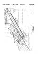
- FIG. 1is a perspective view showing the bipolar probe device of the present invention in position to coagulate and stop a flow of blood from a damaged blood vessel in an exemplary arthroscopic procedure in the subacromial space of a shoulder;
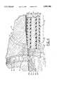
- FIG. 2is an enlarged isometric view of the distal end of the bipolar coagulation probe of this invention positioned adjacent a bleeding blood vessel or "bleeder" in a section of connective tissue that is undergoing arthroscopy, a portion of which tissue is illustrated in cross-section to show the damaged and bleeding blood vessel more clearly, and illustrating current flow through the adjacent tissue, blood, and immersing sterile fluid;
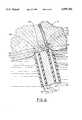
- FIG. 3is an isometric view similar to FIG. 2, but illustrating a coagulated blood vessel and the resulting current flow through the sterile fluid after coagulation is accomplished;
- FIG. 4is an enlarged view in cross-section of the bipolar probe of the present invention being used to coagulate a bleeder in connective tissue with model electrical parallel circuit superimposed to illustrate the operation of the probe according to this invention during coagulation;
- FIG. 5is an enlarged view in cross-section similar to FIG. 5, but illustrating the self-limiting feature of this invention after coagulation has been accomplished.
- FIG. 6is an enlarged cross-sectional view of the distal end of the probe in an orientation that is closer to normal to the tissue as it is sometimes to coagulate bleeders, especially smaller bleeders that can be accommodated between the distal ends of the inner electrode and the outer electrode;
- FIG. 7is an enlarged cross-sectional view of the probe in an orientation similar to FIG. 6, but with the bleeder positioned more in contact with the distal end of the inner electrode;
- FIG. 8is a cross-sectional view of the probe 10 oriented at an angle to the tissue surface
- FIG. 9is a perspective view of an alternate probe configuration of this invention.
- FIG. 10is a perspective view of another alternate probe configuration of this invention.
- the bipolar coagulation probe 10 of the present inventionis illustrated in FIG. 1 in a typical application of coagulating and stemming the flow of blood 26' from a damaged and bleeding blood vessel during arthroscopic surgery in the subacromial space 56 of a shoulder, although it can also be used in much the same way in the intra-articular spaces in shoulders and knees as well as in elbows, wrists, hips, and ankles.
- An enlarged view of the distal portion of the bipolar coagulation probe 10 of the present inventionis shown in FIG. 2 positioned adjacent a damaged and bleeding blood vessel 12 at the exposed surface 14 of a layer of connective tissue 16, such as, for example but not for limitation, the subacromial space 56 in the shoulder.
- the damaged blood vessel 12may be any one of many blood vessels 12' in the connective tissue 16 and, for purposes of illustration and explanation of this invention, has been cut or ruptured by a rotary shaver (not shown) or other tool used by an orthopedic surgeon to ablate (remove) chondromalacia (damaged, worn, or diseased cartilage) or to remove connective tissue during arthroscopy.
- the probeis shown immersed in a sterile fluid 28, which is injected into and flows through the subacromial space 56 during arthroscopy to expand the surrounding tissue (not shown in FIG. 2) and clear debris (not shown) created by the surgical procedure and to keep the surgeon's field of vision into the space clear.
- the sterile fluid 28is preferably a normal saline, ringer lactate, or other fluid used in arthroscopic surgery.
- the blood 26is shown in FIG. 2 flowing out of the damaged or severed end or "bleeding area" 15 of the blood vessel 12 into the sterile fluid 28, where it forms a plume of blood 26' diluted by the sterile fluid 28.
- the exposed peripheral surface 22 of the outer electrode 20 at the distal end of the probe 10is positioned in contact with the exposed surface 14 of the connective tissue 16 adjacent the damaged blood vessel or "bleeder" 12.
- the RF electric power source indicated diagrammatically at 36is turned on causing RF current to flow, as indicated by arrow 24, through the portion of the connective tissue 16 that is in contact with the outer electrode 20 and, as indicated by arrow 32, through the blood 26 that is in the damaged end of the blood vessel 12 and that is escaping from the damaged blood vessel 12 into the sterile fluid 28 and to the inner electrode 30.
- the currentis an RF (radio frequency) alternating current, so it flows in both directions, but the arrows 24, 32, while not strictly technically accurate, do depict in a simplified diagrammatic manner the current path through the connective tissue 16 and blood 26 between the outer electrode 20 and the inner electrode 30 in a sufficient manner to describe the invention, as will be understood by persons skilled in the art.
- An important feature of this inventionis the biophysics, i.e., self-selectivity, of the current path 24, 32 initially between the outer electrode 20 and the inner electrode 30, as described above, and then self-limiting the current flowing in the connective tissue 16 and diverting to an alternate path to flow predominately directly from the outer electrode 20 through the sterile fluid 28 to the inner electrode 30, as will also be described in more detail below.
- the overall structure of the probe 10is similar to the structure described in U.S. Pat. No. 5,089,002, which is incorporated herein by reference, but with several significant differences that are explained below. Similar to that structure, the probe 10 of this invention preferably has a coaxial bipolar arrangement with the elongated outer electrode 20 positioned preferably concentrically around the elongated inner electrode 30 and with an elongated concentric electrical inner insulation layer 40 positioned between the outer electrode 20 and the inner electrode 30. Portions of the outer electrode 20 and the inner insulation layer 40 adjacent their respective distal ends 21, 41 are shown cut away in FIG. 3 to reveal this structure more clearly.
- the proximal end 45 of outer housing 44terminates in a plug 46 with two prongs 48, 49, as shown in FIG.
- the probe 10 of this inventionhas an elongated outer electrical insulation sleeve 42 concentrically around the outer electrode 20, as shown in FIGS. 1-5.
- the distal ends 21, 41, 31 of the outer electrode 20, inner insulation layer 40, and inner electrode 30, respectively, of the probe 10 of the present inventionextend longitudinally a distance beyond the distal end 43 of the outer insulation sleeve 42 to leave a length of exposed peripheral surface 22 of the outer electrode 20, as best seen in FIGS. 2-5.
- This length of exposed peripheral surface 22 of outer electrode 20provides the ability to make a substantial sized electrical contact between the connective tissue 16 and the outer electrode 20 adjacent a bleeder 12 while maintaining the inner electrode 30 spaced a small distance away from the connective tissue 16 so that the electric current path to the inner electrode 30 is completed by the sterile fluid 28 and/or the flowing blood 26, as described above.
- Such electrical contactis preferably, but not necessarily, made with this structure by placing the exposed peripheral surface 22 substantially tangential to, and in contact with, the exposed surface 14 of the connective tissue 16, as illustrated in FIGS. 1-5. Also, while not essential, it is preferable to terminate the distal ends 21, 31, 41 of the outer electrode 20, inner electrode 30, and inner insulation layer 40, respectively, substantially in a common plane perpendicular to the longitudinal axis 38 of the probe 10, as illustrated in FIGS. 2-5, although the inner electrode 30 could protrude longitudinally slightly beyond the outer electrode 20. With this configuration, there is no rotationally preferred orientation of the probe 10 with respect to the connective tissue 16 or with respect to the bleeder 12.
- the outer electrode 20 and inner electrode 30be made of a malleable metal or alloy, for example aluminum, which can be easily formed or bent into any desired shape or configuration to enable ready access and optimum positioning of the probe tip 10 in places that are tight or difficult to reach, as illustrated in FIG. 1.
- the inner insulation layer 40 and outer insulation sleeve 42can be any of a variety of high temperature, flexible plastics, such as, for example, poly vinylidene flouride (PVDF), silicone rubber, tetrafluorethylene (TeflonTM), poly ether ether ketone (PEEK), or perfluoralkoxy (PFA), as is understood by persons skilled in the art.
- PVDFpoly vinylidene flouride
- TeflonTMsilicone rubber
- PEEKpoly ether ether ketone
- PFAperfluoralkoxy
- the probe 10 of this inventionis particularly suited for use in coagulating bleeders encountered during arthroscopy in the intra-articular and sub-acromial spaces in shoulder joints and in the intra-articular spaces in knee joints, although it can also be used in similar applications to coagulate bleeders in shoulders, elbows, wrists, hips, knees, and ankles.
- the malleable probe 10, as described aboveis curved at 52 and 53 to enhance access and optimal positioning in the subacromial space 56 in the shoulder.
- the probe 10being malleable, as described above, enables the surgeon to shape and reshape the probe 10 readily and easily to any desired configuration.
- the sterile fluid solution 28is preferably a normal saline fluid, so it will conduct electric current. It is preferred, although not essential, that the blood 26 has an electrolyte density about the same as, or even slightly higher than, the normal saline fluid 28 so that the blood is as conductive as, and possibly slightly more conductive than, the normal saline fluid 28.
- the blood 26is also usually more conductive than the surrounding connective tissue 16. Since the electric current will find paths of least resistance to flow between the outer electrode 20 and the inner electrode 30, and since the outer electrode 20 and inner electrode 30 are both positioned adjacent the bleeder 12, a substantial portion of the electric current will flow initially through the bleeding area 15.
- That current path through the bleeding area 15requires at least some of the current to flow through the small portion of connective tissue 16 that is between the outer electrode 24 and blood vessel 12, as indicated by arrow 24.
- Poweris the product of the square of the current I times the resistance R, i.e., I 2 R, so that power is dissipated in the blood 26 at and near the bleeding area 15, where the current is most concentrated and in the small portion of the surrounding connective tissue 16 between the outer electrode 24 and the blood vessel 12. Power dissipates in the form of heat.
- the previous current flow 24 through connective tissue 16is self-limiting to coincide with coagulation 34 of the blood 26 at the bleeding area 15, which avoids unnecessary heating and tissue necrosis in the connective tissue 16 or damage to other blood vessels 12' in the proximity, but which are not bleeding, even if the probe 10 is held in the same position with the RF electric power turned on after coagulation 60 occurs.
- the first parallel circuit 70extends generally from the portion of the peripheral surface 22 of outer conductor 20 that is in contact with the connective tissue 16 (i) through the small portion of connective tissue 16 that is between the peripheral surface 22 and the damaged blood vessel 12, represented electrically by the resistor R 1 , (ii) through the blood 26 at and near the bleed area 15, represented electrically by the resistor R 2 , and (iii) through the portion of the sterile fluid 28 that is between the diluted blood 26' and the distal end 31 of the center electrode 30, represented electrically by the resistor R 3 .
- the second parallel circuit 80extends generally from the portion of the peripheral surface 22 that is in contact with the sterile fluid 28 (i) through the sterile fluid 28, represented electrically by resistor R 4 , and (ii) through the sterile fluid 28 that is in contact with the distal end 31 of the center electrode 30, represented by the resistor R 3 .
- the parallel circuits 70, 80 described aboveprovide only a simplified electrical model which could have many variations, because the electric currents in this fluid and tissue environment can flow in indefinite variations, depending on many variables, including, but not limited to, relative conductivities of tissue 16, blood 26, diluted blood 26', and sterile fluid 28, as well as relative positions and spacings between the probe 10, blood vessel 12, plume of diluted blood 26', and the like.
- the bipolar probe 10 of the present inventionfunctions very well in arthroscopy, which previously known bipolar probes are incapable of doing, and the resulting volume of necrosis is significantly smaller than would be possible with a monopolar probe 37.
- the bipolar probe 10is positioned adjacent the bleeder 12 preferably with a portion of the exposed peripheral surface 22 of the outer electrode 20 in contact with a sufficient area of connective tissue 16 so that electric current flows as indicated by the arrows 24, 32, as described above, but with the distal end 31 of the inner electrode 30 preferably spaced a distance away from the tissue 16 and bleed area 15.
- the surgeonpress the exposed surface 22 of outer electrode 20 into the tissue 16 enough to get a large enough contact area between the outer probe 20 and the tissue 16 to keep the current density in the contact area low enough to keep the temperature of the tissue 16 at the contact area under 100° C., so it does not vaporize. Yet, the exposed surface 22 is not so large that the current density is insufficient to heat the tissue above 50° C., where tissue effects or surgical activity, such as desiccation and blood coagulation, begins. Initially, therefore, a substantial amount of electric current flows through the tissue 16 represented by R 1 , the blood 12 in bleed area 15 represented by R 2 , and the sterile fluid 28 represented by R 3 in the first parallel circuit 70.
- the heat produced by the electric current flowing through the tissues and blood of the first parallel circuit 70desiccate or dry the cellular structure of the adjacent end portion 13 of the blood vessel 12 causing it to shrink, as illustrated in FIG. 5, to at least partially close the damaged or severed blood vessel 12.
- the heat produced by the current flowing in the bleeding area 15coagulates the blood 26 in the end portion 13 of the blood vessel 12 to form a plug of coagulated blood 60.
- the combination of the coagulated blood plug 60 with the shrunken end portion 13 of the blood vessel 12effectively stems the flow of blood 26 from the blood vessel 12, as illustrated in FIG. 5.
- the heat produced by electric current flowing through tissue 16causes a small amount of necrosed tissue 62 around the end 13 of blood vessel 12, as also illustrated in FIG. 5.
- the coagulated plug 60 and the necrosed tissue 62which comprise desiccated (dried) cell masses, do not conduct electricity nearly as well as the blood 26 and tissue 16 did or nearly as well as the sterile fluid 28 does. Therefore, as the necrosis 62 and the coagulated plug 60 form, the respective resistances R 1 and R 2 increase until current flow in the first parallel circuit 70 virtually stops, and virtually all of the current flow between the outer conductor 20 and the inner conductor 30 shifts automatically to the second parallel circuit 80 through the sterile fluid 28, as indicated by arrows 36, 36' in FIG. 5, where resistance R 4 remains substantially unchanged. Of course, as current flow through the tissue 16 and blood 26 stops, heat production in tissue 16 and blood 26 also stops.
- tissue 16 and blood 26only migrates a small distance into the tissue 16 and blood vessel 12, as indicated by the boundary line 47 in FIG. 5, before the current flow shifts away from the tissue 16 and blood 26 path of the first parallel circuit 70 almost entirely to the sterile fluid 28 path of the second parallel circuit 80. Thereafter, no further heat, thus no further necrosis of tissue 16 or coagulation of blood 26 occurs, regardless of how long the probe 10 remains in that position with the power turned on.
- This self-limiting feature of this inventionin which the initial denaturing of tissue 16 and coagulation of blood 26 results in increased resistance and stopping the heat-producing flow of electric current through the tissue 16 and blood 26, diverting the electric current flow instead almost entirely to the second parallel circuit 80 of the sterile fluid, allows fast and effective stemming of bleeders, but also prevents excessive and unnecessarily deep necrosis of tissue 16. It also allows enough heat to desiccate or dry the tissue cells, but stops the electric current, thus heat production, before cell vaporization occurs.
- the volume of necrosis for the bipolar probe 10 according to this inventionmay be only about three millimeters deep and three millimeters wide.
- the distal ends 21, 31 of the respective outer electrode 20 and inner electrode 30are both positioned in contact with the tissue 16, preferably, but not necessarily, with the bleeding area 115 of the small bleeder 112 approximately between the distal end 21 of the outer electrode 20 and the distal end 31 of the inner electrode 30.
- the current path indicated by arrow 122 between the outer electrode 20 and the inner electrode 30 through the blood vessel 112will usually have a higher current density than the remaining current path 136 through the tissue 16 due to the lesser resistance of the blood 126 in the blood vessel 112 as compared to the resistance of the surrounding tissue 16.
- This current distribution of paths 122, 136 through the tissue 16 and blood vessel 112is actually circular and generally corresponding to the periphery of the distal end of the probe 10, which does not show well in the cross-section of FIG. 6, but which will be understood by persons skilled in the art, with the arrow 12 representing current flow through the blood vessel 112 and the tissue 16 that is adjacent the distal end of the probe 10.
- the parallel circuit 170comprises in series the resistance R 1 ' through the tissue 16 one side of the bleeder 112, the resistance R 2 ' through the blood 126, and the resistance R 3 ' through the tissue on the other side of the bleeder 112 that is adjacent the distal end 31 of inner electrode 30.
- the parallel circuit 180comprises in series the resistance R 4 ' of the tissue 16 that is adjacent the distal end 21 of outer electrode 20 (other than the R 1 ' portion of tissue 16) in series with the resistance R 3 ' of the tissue 16 that is adjacent the distal end 31 of inner electrode 30.
- the sum of the resistances R 1 ', R 2 ', and R 3 ' in parallel circuit 170is less than, or at least not substantially more than, the sum of the resistances R 4 ' and R 3 ' in parallel circuit 180.
- the current shift to circuit 180will also increase heat in path 136 and cause desiccation and necrosis of the tissue 16 in near path 136.
- depth of such desiccation and necrosis into the tissue 16is limited to the tissue 16 within a distance from the distal end of probe 10 that is generally less than the diameter of the outer electrode 20. This limited depth is due to the fact that the current will not continue to extend over farther into tissue 16 as the tissue 16 adjacent the probe 10 is desiccated and necrosed.
- the goalis to desiccate and shrink bleeder vessels 112, desiccate and coagulate blood 126, and, if necessary, desiccate and necrose some small amount of tissue 16 immediately surrounding the bleeder 112 in order to achieve hemostasis, but not to vaporize cells or to carbonize cells. It is counter productive to vaporize or carbonize cells, because vaporization does not stop bleeding effectively, and carbonation of cells inhibits healing.
- probe 10 for hemostasis of a bleeding blood vessel 212is not preferred, but it does work.
- This applicationis similar to that of FIG. 6, except inner electrode 30 is positioned directly on the bleeding blood vessel 212.
- the initial current path 222includes the less resistive blood 226 in blood vessel 212, represented in the model by resistance R 2 ", as well as some of the tissue 16 that is adjacent the distal end of the probe 110, represented by the resistances R 1 ", R 3 " and R 4 ".
- bipolarmeans that it is possible for both the outer electrode 20 and the inner electrode 30 to be surgically active, even though they might not both always be actually surgically active means that sufficient heat is produced in cells at or immediately adjacent the electrode to alter cells physically, such as desiccation, coagulation, necrosis, ablation, vaporization, carbonization and the like. Therefore, to be truly bipolar for purposes of this invention, the probe 10 must be capable of causing such surgical activity in tissue and/or blood cells at or immediately adjacent both the outer electrode 20 and the inner electrode 30.
- the surface area of either electrodemust be less than about ten times as large as the surface area of the other electrode to keep the ratio of the respective surface areas less than about 10:1.
- the surface area of the outer electrode 20is effectively the sum of the respective uninsulated surface areas of the peripheral surface 22 and the distal end 21 of the outer electrode 20.
- the surface area of the inner electrode 30is essentially the uninsulated surface area of the distal end 31 of inner electrode 30. If the distal end 31 of the inner electrode 30 should also extend slightly beyond the inner insulation, as mentioned above, then the surface area of the inner electrode 30 would also include any additional uninsulated surface area of the periphery of the inner electrode 30 for purposes of the 10:1 ratio of respective surface areas of electrodes described above.
- outer electrode 20 and inner electrode 30within the 10:1 ratio described above does not mean that surgical activity occurs at or immediately adjacent both the outer electrode 20 and the inner electrode 30 at all times.
- the distal end of the inner electrode 30is spatially removed from the tissue 16, so there is no actual surgical activity strictly at the inner electrode 30 while desiccation, shrinking, coagulation, and necrosis in the blood vessel 12, blood 26, and tissue 16 occurs, as described above.
- such surgical activitystops also at and near outer electrode 20.
- the probe 10must be bipolar as described above.
- the specific length of the exposed surface 22 of outer electrode 20is not critical as long as the respective electrode surface areas of outer electrode 20 and inner electrode 30 remain within the 10:1 ratio for bipolarity described above.
- the shorter the lengththe more focused the electrical current path 24 will be; therefore, less overall tissue necrosis. Exposing more of the metal surface 22 of outer electrode 20 results in defocusing the current path 24 and will result in additional tissue necrosis beyond the bleeding point, but also avoids excessive current density that could vaporize tissue.
- the diameter of the probe 10is preferred in the range of 3.0-10.0 mm with the inner electrode 30 being about 1-2 mm diameter and the outer electrode 20 being about 2.5-5.0 mm diameter.
- the inner insulation 40is preferably in the range of about 0.2 to 3 mm thick and the outer insulation is preferably in the range of about 0.2-3 mm thick.
- the length of the probe 10should be long enough to extend through an incision or cannula to reach any desired location in the shoulder or knee joint. It is also preferred, but not necessary, that the RF current supply is approximately three-hundred (300 KHz) to three megahertz (3 MHz) and, optimally, the RF current supply is approximately five-hundred kilohertz (500 KHz).
- the powershould be in the range of about twenty to one-hundred watts and is preferably in the range between forty and seventy watts into a load impedance in the range of about 25-1000 ohms preferably about 50-250 ohms, for example, 100 ohms to achieve the desired desiccation and shrinking of blood vessels, coagulation of blood, and necrosis of tissue as described above along with the self-selective current paths and self-limiting of surgical activity according to this invention.
- the circular cross-section of probe 10 with the outer electrode 20 positioned concentrically around the inner electrode 30has advantages, such as being equally effective regardless of the rotational position of the probe about its longitudinal axis 38 in relation to the tissue 16, as mentioned above.
- This configurationalso accommodates variations in angles of the longitudinal axis 38 with the surface of the tissue 16 very easily.
- the probe 10is shown in FIG. 8 with its longitudinal axis 38 at about a 45° angle 98 with the surface of the tissue 16 adjacent the bleeder 12 and with the distal ends 21, 31 of the outer electrode 20 and the inner electrode 30 pushed into the tissue 16 enough to deform the tissue 16 at the surface where the bleeder is injured.
- part, but not all, of the distal end 21 of outer electrode 20can be placed in contact with tissue 16, depending on how much electric contact area, thus current density, the surgeon wants or needs to coagulate the bleeder 12 and necrose just enough tissue 16 around the damaged bleeder 12, as indicated by phantom lines 47 to stem the bleeding.
- the angle 98is small enough to leave the inner electrode immersed in fluid 28 but not in contact with tissue 16, then the embodiment shown in FIGS. 2-5 prevails and operates as described above.
- the cross-section of the probedoes not have to be circular, however.
- an alternate probe 300 with a square cross-section of concentric inner electrode 330, inner insulation 340, outer electrode 320, and outer insulation 342, as shown in FIG. 9can be used according to this invention.
- Other cross-sectional configurations, such as oval polygonal, or other shapescan also be used.
- Etis also not necessary for the electrodes to be concentric.
- the probe 400 shown in FIG. 10has an inner electrode 430 sandwiched between two outer electrodes 420, 420' with respective inner insulation layers 440, 440' intervening.
- the two outer electrodes 420, 420'can be, but are not necessarily at the same electrical potential as each other.
- the outer insulation 442surrounds all of the electrodes.
- Many other variations of the inventionare also possible to provide the bipolar surgical activity within the surface area ratios and exposed outer electrode parameters described above.
Landscapes
- Health & Medical Sciences (AREA)
- Surgery (AREA)
- Engineering & Computer Science (AREA)
- Life Sciences & Earth Sciences (AREA)
- Heart & Thoracic Surgery (AREA)
- Biomedical Technology (AREA)
- Nuclear Medicine, Radiotherapy & Molecular Imaging (AREA)
- Otolaryngology (AREA)
- Neurology (AREA)
- Neurosurgery (AREA)
- Physics & Mathematics (AREA)
- Plasma & Fusion (AREA)
- Medical Informatics (AREA)
- Molecular Biology (AREA)
- Animal Behavior & Ethology (AREA)
- General Health & Medical Sciences (AREA)
- Public Health (AREA)
- Veterinary Medicine (AREA)
- Surgical Instruments (AREA)
Abstract
Description
Claims (21)
Priority Applications (3)
| Application Number | Priority Date | Filing Date | Title |
|---|---|---|---|
| US08/770,241US5895386A (en) | 1996-12-20 | 1996-12-20 | Bipolar coagulation apparatus and method for arthroscopy |
| AU56199/98AAU5619998A (en) | 1996-12-20 | 1997-12-19 | Bipolar coagulation apparatus and method for arthroscopy |
| PCT/US1997/023853WO1998027879A1 (en) | 1996-12-20 | 1997-12-19 | Bipolar coagulation apparatus and method for arthroscopy |
Applications Claiming Priority (1)
| Application Number | Priority Date | Filing Date | Title |
|---|---|---|---|
| US08/770,241US5895386A (en) | 1996-12-20 | 1996-12-20 | Bipolar coagulation apparatus and method for arthroscopy |
Publications (1)
| Publication Number | Publication Date |
|---|---|
| US5895386Atrue US5895386A (en) | 1999-04-20 |
Family
ID=25087904
Family Applications (1)
| Application Number | Title | Priority Date | Filing Date |
|---|---|---|---|
| US08/770,241Expired - LifetimeUS5895386A (en) | 1996-12-20 | 1996-12-20 | Bipolar coagulation apparatus and method for arthroscopy |
Country Status (3)
| Country | Link |
|---|---|
| US (1) | US5895386A (en) |
| AU (1) | AU5619998A (en) |
| WO (1) | WO1998027879A1 (en) |
Cited By (101)
| Publication number | Priority date | Publication date | Assignee | Title |
|---|---|---|---|---|
| US6071281A (en)* | 1998-05-05 | 2000-06-06 | Ep Technologies, Inc. | Surgical method and apparatus for positioning a diagnostic or therapeutic element within the body and remote power control unit for use with same |
| US6102046A (en)* | 1995-11-22 | 2000-08-15 | Arthrocare Corporation | Systems and methods for electrosurgical tissue revascularization |
| US6120496A (en)* | 1998-05-05 | 2000-09-19 | Scimed Life Systems, Inc. | Surgical method and apparatus for positioning a diagnostic or therapeutic element within the body and coupling device for use with same |
| US6142994A (en)* | 1994-10-07 | 2000-11-07 | Ep Technologies, Inc. | Surgical method and apparatus for positioning a diagnostic a therapeutic element within the body |
| US6152920A (en)* | 1997-10-10 | 2000-11-28 | Ep Technologies, Inc. | Surgical method and apparatus for positioning a diagnostic or therapeutic element within the body |
| US6267760B1 (en) | 1998-05-05 | 2001-07-31 | Scimed Life Systems, Inc. | Surgical method and apparatus for positioning a diagnostic or therapeutic element within the body and forming an incision in tissue with minimal blood loss |
| WO2001066027A1 (en)* | 2000-03-06 | 2001-09-13 | Everest Medical Corporation | Electrosurgical instrument with suction capability |
| US20020068930A1 (en)* | 1995-11-22 | 2002-06-06 | Arthrocare Corporation | Systems and methods for electrosurgical tendon vascularization |
| US6406476B1 (en) | 2000-08-15 | 2002-06-18 | Kirwan Surgical Products, Inc. | Bipolar, fluid assisted coagulator/ablator probe for arthroscopy |
| US6416505B1 (en) | 1998-05-05 | 2002-07-09 | Scimed Life Systems, Inc. | Surgical method and apparatus for positioning a diagnostic or therapeutic element within the body and pressure application probe for use with same |
| US6468272B1 (en) | 1997-10-10 | 2002-10-22 | Scimed Life Systems, Inc. | Surgical probe for supporting diagnostic and therapeutic elements in contact with tissue in or around body orifices |
| US20020183771A1 (en)* | 2001-03-28 | 2002-12-05 | Vascular Control Systems, Inc. | Method and apparatus for the detection and ligation of uterine arteries |
| US6506156B1 (en) | 2000-01-19 | 2003-01-14 | Vascular Control Systems, Inc | Echogenic coating |
| US20030055454A1 (en)* | 2001-03-14 | 2003-03-20 | Cardiodex Ltd. | Balloon method and apparatus for vascular closure following arterial catheterization |
| US6540742B1 (en)* | 1997-07-24 | 2003-04-01 | Stuart Thomas | Intraoperative endocardial and epicardial ablation probe |
| US6550482B1 (en) | 2000-04-21 | 2003-04-22 | Vascular Control Systems, Inc. | Methods for non-permanent occlusion of a uterine artery |
| US20030120306A1 (en)* | 2000-04-21 | 2003-06-26 | Vascular Control System | Method and apparatus for the detection and occlusion of blood vessels |
| US20030120286A1 (en)* | 2001-03-28 | 2003-06-26 | Vascular Control System | Luminal clip applicator with sensor |
| US20030130658A1 (en)* | 2001-12-27 | 2003-07-10 | Goble Coliin C.O. | Surgical instrument |
| US6602251B2 (en) | 1998-12-08 | 2003-08-05 | Vascular Control Systems, Inc. | Device and methods for occlusion of the uterine artieries |
| US20030191391A1 (en)* | 2002-04-04 | 2003-10-09 | Burbank Fred H. | Doppler directed suturing and compression device and method |
| US6635065B2 (en) | 2000-11-16 | 2003-10-21 | Vascular Control Systems, Inc. | Doppler directed suture ligation device and method |
| US6638286B1 (en) | 2000-11-16 | 2003-10-28 | Vascular Control Systems, Inc. | Doppler directed suture ligation device and method |
| US6645200B1 (en) | 1997-10-10 | 2003-11-11 | Scimed Life Systems, Inc. | Method and apparatus for positioning a diagnostic or therapeutic element within the body and tip electrode for use with same |
| WO2003068311A3 (en)* | 2002-02-13 | 2004-03-25 | Arthrocare Corp | Electrosurgical apparatus and methods for treating joint tissue |
| US20040092979A1 (en)* | 2001-03-28 | 2004-05-13 | Vascular Control System | Occlusion device with deployable paddles for detection and occlusion of blood vessels |
| US20040097961A1 (en)* | 2002-11-19 | 2004-05-20 | Vascular Control System | Tenaculum for use with occlusion devices |
| US20040097962A1 (en)* | 2002-11-19 | 2004-05-20 | Vascular Control System | Deployable constrictor for uterine artery occlusion |
| US6746447B2 (en) | 1993-05-10 | 2004-06-08 | Arthrocare Corporation | Methods for ablating tissue |
| US6749604B1 (en) | 1993-05-10 | 2004-06-15 | Arthrocare Corporation | Electrosurgical instrument with axially-spaced electrodes |
| US6763836B2 (en) | 1998-06-02 | 2004-07-20 | Arthrocare Corporation | Methods for electrosurgical tendon vascularization |
| US20040153060A1 (en)* | 2003-02-04 | 2004-08-05 | Cardiodex Ltd. | Methods and apparatus for hemostasis following arterial catheterization |
| US20040153105A1 (en)* | 2003-01-30 | 2004-08-05 | Vascular Control Systems, Inc. | Uterine artery occlusion clamp |
| US20040202694A1 (en)* | 2003-04-11 | 2004-10-14 | Vascular Control Systems, Inc. | Embolic occlusion of uterine arteries |
| US6827714B2 (en) | 2001-03-07 | 2004-12-07 | Scimed Life Systems, Inc. | Internal indifferent electrode device for use with lesion creation apparatus and method of forming lesions using the same |
| US20040260280A1 (en)* | 2003-05-01 | 2004-12-23 | Sartor Joe Don | Suction coagulator with dissecting probe |
| US20050101974A1 (en)* | 2003-02-05 | 2005-05-12 | Vascular Control Systems, Inc. | Vascular clamp for caesarian section |
| US6896674B1 (en) | 1993-05-10 | 2005-05-24 | Arthrocare Corporation | Electrosurgical apparatus having digestion electrode and methods related thereto |
| US20050113852A1 (en)* | 2003-11-20 | 2005-05-26 | Vascular Control Systems, Inc. | Uterine artery occlusion device with cervical receptacle |
| US20050113634A1 (en)* | 2003-11-25 | 2005-05-26 | Vascular Control Systems, Inc. | Occlusion device for asymmetrical uterine artery anatomy |
| US6949096B2 (en) | 1998-01-21 | 2005-09-27 | Arthrocare Corporation | Electrosurgical ablation and aspiration apparatus having flow directing feature and methods related thereto |
| US20050283148A1 (en)* | 2004-06-17 | 2005-12-22 | Janssen William M | Ablation apparatus and system to limit nerve conduction |
| US20050283149A1 (en)* | 2004-06-08 | 2005-12-22 | Thorne Jonathan O | Electrosurgical cutting instrument |
| US20060015144A1 (en)* | 2004-07-19 | 2006-01-19 | Vascular Control Systems, Inc. | Uterine artery occlusion staple |
| US20060015165A1 (en)* | 2001-12-04 | 2006-01-19 | Bertolero Arthur A | Conduction block verification probe and method of use |
| US20060079889A1 (en)* | 2001-04-19 | 2006-04-13 | Manzo Scott | Wristed robotic tool with replaceable end-effector cartridges |
| US20060079884A1 (en)* | 2004-10-08 | 2006-04-13 | Intuitive Surgical Inc. | Robotic tool with wristed monopolar electrosurgical end effectors |
| US20060106109A1 (en)* | 2004-10-27 | 2006-05-18 | Burbank Fred H | Short term treatment for uterine disorder |
| US20060111709A1 (en)* | 2004-11-24 | 2006-05-25 | Gyrus Group Plc | Electrosurgical instrument |
| US20060111710A1 (en)* | 2004-11-24 | 2006-05-25 | Gyrus Group Plc | Electrosurgical instrument |
| US7094215B2 (en) | 1997-10-02 | 2006-08-22 | Arthrocare Corporation | Systems and methods for electrosurgical tissue contraction |
| US20060217705A1 (en)* | 2005-02-17 | 2006-09-28 | Baylis Medical Company Inc. | Electrosurgical device with discontinuous flow density |
| US7115127B2 (en) | 2003-02-04 | 2006-10-03 | Cardiodex, Ltd. | Methods and apparatus for hemostasis following arterial catheterization |
| US20060241337A1 (en)* | 2003-03-28 | 2006-10-26 | Vascular Control Systems, Inc. | Uterine tissue monitoring device and method |
| US20060264929A1 (en)* | 2001-12-27 | 2006-11-23 | Gyrus Group Plc | Surgical system |
| US20060267255A1 (en)* | 2003-01-31 | 2006-11-30 | Daniela Tomova | Process for producing a performance enhanced single-layer blow-moulded container |
| US20070027449A1 (en)* | 2002-03-05 | 2007-02-01 | Baylis Medical Company Inc. | Electrosurgical device and methods |
| US20070049973A1 (en)* | 2005-08-29 | 2007-03-01 | Vascular Control Systems, Inc. | Method and device for treating adenomyosis and endometriosis |
| US7201750B1 (en) | 1992-01-07 | 2007-04-10 | Arthrocare Corporation | System for treating articular cartilage defects |
| US7223279B2 (en) | 2000-04-21 | 2007-05-29 | Vascular Control Systems, Inc. | Methods for minimally-invasive, non-permanent occlusion of a uterine artery |
| USD547867S1 (en) | 2006-04-17 | 2007-07-31 | Synergetics Usa, Inc. | Surgical instrument handle |
| US20070203402A1 (en)* | 2002-03-05 | 2007-08-30 | Baylis Medical | Elongate member providing a variation in radiopacity |
| US7276063B2 (en) | 1998-08-11 | 2007-10-02 | Arthrocare Corporation | Instrument for electrosurgical tissue treatment |
| US20080004619A1 (en)* | 2006-06-28 | 2008-01-03 | Synergetics Usa, Inc. | Electrosurgical bipolar instrument |
| USD560278S1 (en) | 2005-09-27 | 2008-01-22 | Synergetics Usa, Inc. | Electrosurgical bipolar cutting/coagulating instrument |
| US20080045935A1 (en)* | 1996-10-22 | 2008-02-21 | Cox James L | Surgical system and procedure for treatment of medically refractory atrial fibrillation |
| US7429260B2 (en) | 1996-07-16 | 2008-09-30 | Arthrocare Corporation | Systems and methods for electrosurgical tissue contraction within the spine |
| US7435247B2 (en) | 1998-08-11 | 2008-10-14 | Arthrocare Corporation | Systems and methods for electrosurgical tissue treatment |
| WO2008014465A3 (en)* | 2006-07-28 | 2008-10-23 | Jnj Technology Holdings Llc | Ablation apparatus and system to limit nerve conduction |
| US20090024124A1 (en)* | 2005-07-14 | 2009-01-22 | Lefler Amy | Methods for treating the thoracic region of a patient's body |
| US20090054962A1 (en)* | 2002-03-05 | 2009-02-26 | Baylis Medical Company Inc. | Methods for treating the thoracic region of a patient's body |
| US20100191250A1 (en)* | 2002-04-18 | 2010-07-29 | Intuitive Surgical Operations, Inc. | Robotic surgical tool for pluggable end-effectors |
| US20100324555A1 (en)* | 2009-06-19 | 2010-12-23 | Tyco Healthcare Group Lp | Thermal Barrier for Suction Coagulator |
| US20110118698A1 (en)* | 2009-11-13 | 2011-05-19 | Searete Llc, A Limited Liability Corporation Of The State Of Delaware | Device, system, and method for targeted delivery of anti-inflammatory medicaments to a mammalian subject |
| US20110117151A1 (en)* | 2009-11-13 | 2011-05-19 | Searete Llc. A Limited Liability Corporation Of The State Of Delaware | Device,system, and method for targeted delivery of anti-inflammatory medicaments to a mammalian subject |
| US20110118653A1 (en)* | 2009-11-13 | 2011-05-19 | Searete Llc, A Limited Liability Corporation Of The State Of Delaware | Device, system, and method for targeted delivery of anti-inflammatory medicaments to a mammalian subject |
| US8012153B2 (en) | 2003-07-16 | 2011-09-06 | Arthrocare Corporation | Rotary electrosurgical apparatus and methods thereof |
| US20110230879A1 (en)* | 2003-01-31 | 2011-09-22 | Smith & Nephew, Inc. | Cartilage treatment probe |
| US20120053579A1 (en)* | 2010-08-25 | 2012-03-01 | Tyco Healthcare Group Lp | Bipolar Chondroplasty Device |
| US8226640B2 (en) | 2008-03-27 | 2012-07-24 | Bovie Medical Corporation | Laparoscopic electrosurgical electrical leakage detection |
| US8317786B2 (en) | 2009-09-25 | 2012-11-27 | AthroCare Corporation | System, method and apparatus for electrosurgical instrument with movable suction sheath |
| US8323279B2 (en) | 2009-09-25 | 2012-12-04 | Arthocare Corporation | System, method and apparatus for electrosurgical instrument with movable fluid delivery sheath |
| US8355799B2 (en) | 2008-12-12 | 2013-01-15 | Arthrocare Corporation | Systems and methods for limiting joint temperature |
| US8366706B2 (en) | 2007-08-15 | 2013-02-05 | Cardiodex, Ltd. | Systems and methods for puncture closure |
| US8435236B2 (en) | 2004-11-22 | 2013-05-07 | Cardiodex, Ltd. | Techniques for heat-treating varicose veins |
| US8696659B2 (en) | 2010-04-30 | 2014-04-15 | Arthrocare Corporation | Electrosurgical system and method having enhanced temperature measurement |
| US8747400B2 (en) | 2008-08-13 | 2014-06-10 | Arthrocare Corporation | Systems and methods for screen electrode securement |
| US8758336B2 (en) | 2004-08-17 | 2014-06-24 | Encision, Inc. | System and method for monitoring electrosurgical systems |
| US8979834B2 (en) | 2008-03-27 | 2015-03-17 | Bovie Medical Corporation | Laparoscopic electrosurgical electrical leakage detection |
| US9113912B1 (en) | 2015-01-21 | 2015-08-25 | Serene Medical, Inc. | Systems and devices to identify and limit nerve conduction |
| US9119628B1 (en) | 2015-01-21 | 2015-09-01 | Serene Medical, Inc. | Systems and devices to identify and limit nerve conduction |
| US20160262828A1 (en)* | 2011-06-23 | 2016-09-15 | Covidien Lp | Shaped electrode bipolar resection apparatus, system and methods of use |
| US9526556B2 (en) | 2014-02-28 | 2016-12-27 | Arthrocare Corporation | Systems and methods systems related to electrosurgical wands with screen electrodes |
| US9597142B2 (en) | 2014-07-24 | 2017-03-21 | Arthrocare Corporation | Method and system related to electrosurgical procedures |
| US9649148B2 (en) | 2014-07-24 | 2017-05-16 | Arthrocare Corporation | Electrosurgical system and method having enhanced arc prevention |
| US9949789B2 (en) | 2002-03-05 | 2018-04-24 | Avent, Inc. | Methods of treating the sacroiliac region of a patient's body |
| US10786300B2 (en) | 2015-04-13 | 2020-09-29 | Carlos Fernando Bazoberry | Radiofrequency denervation needle and method |
| US11291496B2 (en) | 2002-03-05 | 2022-04-05 | Avent, Inc. | Methods of treating the sacroiliac region of a patient's body |
| US11712290B2 (en)* | 2018-06-08 | 2023-08-01 | RELIGN Corporation | Arthroscopic devices and methods |
| US11844493B2 (en) | 2016-11-17 | 2023-12-19 | Apyx Medical Corporation | Electrosurgical apparatus with dynamic leakage current compensation and dynamic RF modulation |
| US12035961B2 (en) | 2015-04-13 | 2024-07-16 | Carlos Fernando Bazoberry | Radiofrequency denervation needle and method |
Families Citing this family (54)
| Publication number | Priority date | Publication date | Assignee | Title |
|---|---|---|---|---|
| US6053172A (en) | 1995-06-07 | 2000-04-25 | Arthrocare Corporation | Systems and methods for electrosurgical sinus surgery |
| US6024733A (en) | 1995-06-07 | 2000-02-15 | Arthrocare Corporation | System and method for epidermal tissue ablation |
| US7429262B2 (en) | 1992-01-07 | 2008-09-30 | Arthrocare Corporation | Apparatus and methods for electrosurgical ablation and resection of target tissue |
| US7297145B2 (en) | 1997-10-23 | 2007-11-20 | Arthrocare Corporation | Bipolar electrosurgical clamp for removing and modifying tissue |
| US5683366A (en) | 1992-01-07 | 1997-11-04 | Arthrocare Corporation | System and method for electrosurgical tissue canalization |
| US6974453B2 (en) | 1993-05-10 | 2005-12-13 | Arthrocare Corporation | Dual mode electrosurgical clamping probe and related methods |
| US6063079A (en) | 1995-06-07 | 2000-05-16 | Arthrocare Corporation | Methods for electrosurgical treatment of turbinates |
| US6179824B1 (en) | 1993-05-10 | 2001-01-30 | Arthrocare Corporation | System and methods for electrosurgical restenosis of body lumens |
| US6254600B1 (en) | 1993-05-10 | 2001-07-03 | Arthrocare Corporation | Systems for tissue ablation and aspiration |
| US6915806B2 (en) | 1993-05-10 | 2005-07-12 | Arthrocare Corporation | Method for harvesting graft vessel |
| US6602248B1 (en) | 1995-06-07 | 2003-08-05 | Arthro Care Corp. | Methods for repairing damaged intervertebral discs |
| US6203542B1 (en)* | 1995-06-07 | 2001-03-20 | Arthrocare Corporation | Method for electrosurgical treatment of submucosal tissue |
| US6837887B2 (en) | 1995-06-07 | 2005-01-04 | Arthrocare Corporation | Articulated electrosurgical probe and methods |
| US6837888B2 (en) | 1995-06-07 | 2005-01-04 | Arthrocare Corporation | Electrosurgical probe with movable return electrode and methods related thereto |
| WO2003024506A2 (en) | 2001-09-14 | 2003-03-27 | Arthrocare Corporation | Methods and apparatus for treating intervertebral discs |
| US20050004634A1 (en) | 1995-06-07 | 2005-01-06 | Arthrocare Corporation | Methods for electrosurgical treatment of spinal tissue |
| US7179255B2 (en) | 1995-06-07 | 2007-02-20 | Arthrocare Corporation | Methods for targeted electrosurgery on contained herniated discs |
| US7090672B2 (en) | 1995-06-07 | 2006-08-15 | Arthrocare Corporation | Method for treating obstructive sleep disorder includes removing tissue from the base of tongue |
| US7393351B2 (en) | 1995-06-07 | 2008-07-01 | Arthrocare Corporation | Apparatus and methods for treating cervical inter-vertebral discs |
| US7572251B1 (en) | 1995-06-07 | 2009-08-11 | Arthrocare Corporation | Systems and methods for electrosurgical tissue treatment |
| US6896672B1 (en) | 1995-11-22 | 2005-05-24 | Arthrocare Corporation | Methods for electrosurgical incisions on external skin surfaces |
| US7186234B2 (en) | 1995-11-22 | 2007-03-06 | Arthrocare Corporation | Electrosurgical apparatus and methods for treatment and removal of tissue |
| US7357798B2 (en) | 1996-07-16 | 2008-04-15 | Arthrocare Corporation | Systems and methods for electrosurgical prevention of disc herniations |
| US6726684B1 (en) | 1996-07-16 | 2004-04-27 | Arthrocare Corporation | Methods for electrosurgical spine surgery |
| US7104986B2 (en) | 1996-07-16 | 2006-09-12 | Arthrocare Corporation | Intervertebral disc replacement method |
| US6855143B2 (en) | 1997-06-13 | 2005-02-15 | Arthrocare Corporation | Electrosurgical systems and methods for recanalization of occluded body lumens |
| US7070596B1 (en) | 2000-08-09 | 2006-07-04 | Arthrocare Corporation | Electrosurgical apparatus having a curved distal section |
| US20030158545A1 (en) | 2000-09-28 | 2003-08-21 | Arthrocare Corporation | Methods and apparatus for treating back pain |
| US7004941B2 (en) | 2001-11-08 | 2006-02-28 | Arthrocare Corporation | Systems and methods for electrosurigical treatment of obstructive sleep disorders |
| US6920883B2 (en) | 2001-11-08 | 2005-07-26 | Arthrocare Corporation | Methods and apparatus for skin treatment |
| WO2003068055A2 (en) | 2002-02-11 | 2003-08-21 | Arthrocare Corporation | Electrosurgical apparatus and methods for laparoscopy |
| US7297143B2 (en) | 2003-02-05 | 2007-11-20 | Arthrocare Corporation | Temperature indicating electrosurgical apparatus and methods |
| US7491200B2 (en) | 2004-03-26 | 2009-02-17 | Arthrocare Corporation | Method for treating obstructive sleep disorder includes removing tissue from base of tongue |
| US7632267B2 (en) | 2005-07-06 | 2009-12-15 | Arthrocare Corporation | Fuse-electrode electrosurgical apparatus |
| US8876746B2 (en) | 2006-01-06 | 2014-11-04 | Arthrocare Corporation | Electrosurgical system and method for treating chronic wound tissue |
| GB2452103B (en) | 2007-01-05 | 2011-08-31 | Arthrocare Corp | Electrosurgical system with suction control apparatus and system |
| US8882756B2 (en) | 2007-12-28 | 2014-11-11 | Medtronic Advanced Energy Llc | Fluid-assisted electrosurgical devices, methods and systems |
| US9358063B2 (en) | 2008-02-14 | 2016-06-07 | Arthrocare Corporation | Ablation performance indicator for electrosurgical devices |
| US8257350B2 (en) | 2009-06-17 | 2012-09-04 | Arthrocare Corporation | Method and system of an electrosurgical controller with wave-shaping |
| US8372067B2 (en) | 2009-12-09 | 2013-02-12 | Arthrocare Corporation | Electrosurgery irrigation primer systems and methods |
| US8979838B2 (en) | 2010-05-24 | 2015-03-17 | Arthrocare Corporation | Symmetric switching electrode method and related system |
| US10448992B2 (en) | 2010-10-22 | 2019-10-22 | Arthrocare Corporation | Electrosurgical system with device specific operational parameters |
| US9131597B2 (en) | 2011-02-02 | 2015-09-08 | Arthrocare Corporation | Electrosurgical system and method for treating hard body tissue |
| US9168082B2 (en) | 2011-02-09 | 2015-10-27 | Arthrocare Corporation | Fine dissection electrosurgical device |
| US9271784B2 (en) | 2011-02-09 | 2016-03-01 | Arthrocare Corporation | Fine dissection electrosurgical device |
| US9011428B2 (en) | 2011-03-02 | 2015-04-21 | Arthrocare Corporation | Electrosurgical device with internal digestor electrode |
| US9788882B2 (en) | 2011-09-08 | 2017-10-17 | Arthrocare Corporation | Plasma bipolar forceps |
| US9254166B2 (en) | 2013-01-17 | 2016-02-09 | Arthrocare Corporation | Systems and methods for turbinate reduction |
| US9713489B2 (en) | 2013-03-07 | 2017-07-25 | Arthrocare Corporation | Electrosurgical methods and systems |
| US9693818B2 (en) | 2013-03-07 | 2017-07-04 | Arthrocare Corporation | Methods and systems related to electrosurgical wands |
| US9801678B2 (en) | 2013-03-13 | 2017-10-31 | Arthrocare Corporation | Method and system of controlling conductive fluid flow during an electrosurgical procedure |
| US9962150B2 (en) | 2013-12-20 | 2018-05-08 | Arthrocare Corporation | Knotless all suture tissue repair |
| US10420607B2 (en) | 2014-02-14 | 2019-09-24 | Arthrocare Corporation | Methods and systems related to an electrosurgical controller |
| CN109805999B (en)* | 2019-02-19 | 2021-03-30 | 西安外科医学科技有限公司 | Plasma radio frequency bipolar high-frequency surgical knife head capable of being positioned and stretched under endoscope |
Citations (31)
| Publication number | Priority date | Publication date | Assignee | Title |
|---|---|---|---|---|
| US3974833A (en)* | 1973-03-19 | 1976-08-17 | Durden Iii John G | Disposable electrosurgical cautery having optional suction control feature |
| US4043342A (en)* | 1974-08-28 | 1977-08-23 | Valleylab, Inc. | Electrosurgical devices having sesquipolar electrode structures incorporated therein |
| US4181131A (en)* | 1977-02-28 | 1980-01-01 | Olympus Optical Co., Ltd. | High frequency electrosurgical instrument for cutting human body cavity structures |
| US4232676A (en)* | 1978-11-16 | 1980-11-11 | Corning Glass Works | Surgical cutting instrument |
| US4427006A (en)* | 1982-01-18 | 1984-01-24 | Medical Research Associates, Ltd. #1 | Electrosurgical instruments |
| US4562838A (en)* | 1981-01-23 | 1986-01-07 | Walker William S | Electrosurgery instrument |
| US4581021A (en)* | 1985-01-28 | 1986-04-08 | Ergomed | Squeeze-actuated syringe |
| US4719914A (en)* | 1986-12-24 | 1988-01-19 | Johnson Gerald W | Electrosurgical instrument |
| US4781175A (en)* | 1986-04-08 | 1988-11-01 | C. R. Bard, Inc. | Electrosurgical conductive gas stream technique of achieving improved eschar for coagulation |
| US4787891A (en)* | 1987-07-13 | 1988-11-29 | Paul Levin | Syringe holder and applicator |
| US4800869A (en)* | 1987-02-13 | 1989-01-31 | Olympus Optical Co. Ltd. | Endoscope |
| US4932952A (en)* | 1988-12-20 | 1990-06-12 | Alto Development Corporation | Antishock, anticlog suction coagulator |
| US4998933A (en)* | 1988-06-10 | 1991-03-12 | Advanced Angioplasty Products, Inc. | Thermal angioplasty catheter and method |
| US5009656A (en)* | 1989-08-17 | 1991-04-23 | Mentor O&O Inc. | Bipolar electrosurgical instrument |
| US5084045A (en)* | 1990-09-17 | 1992-01-28 | Helenowski Tomasz K | Suction surgical instrument |
| US5089002A (en)* | 1989-04-06 | 1992-02-18 | Kirwan Surgical Products, Inc. | Disposable bipolar coagulator |
| USRE33925E (en)* | 1984-05-22 | 1992-05-12 | Cordis Corporation | Electrosurgical catheter aned method for vascular applications |
| US5178620A (en)* | 1988-06-10 | 1993-01-12 | Advanced Angioplasty Products, Inc. | Thermal dilatation catheter and method |
| US5277696A (en)* | 1991-11-19 | 1994-01-11 | Delma Elektro- Und Medizinische Apparatebau Gesellschaft Mbh | Medical high frequency coagulation instrument |
| US5281216A (en)* | 1992-03-31 | 1994-01-25 | Valleylab, Inc. | Electrosurgical bipolar treating apparatus |
| US5342357A (en)* | 1992-11-13 | 1994-08-30 | American Cardiac Ablation Co., Inc. | Fluid cooled electrosurgical cauterization system |
| US5366443A (en)* | 1992-01-07 | 1994-11-22 | Thapliyal And Eggers Partners | Method and apparatus for advancing catheters through occluded body lumens |
| US5383876A (en)* | 1992-11-13 | 1995-01-24 | American Cardiac Ablation Co., Inc. | Fluid cooled electrosurgical probe for cutting and cauterizing tissue |
| US5403311A (en)* | 1993-03-29 | 1995-04-04 | Boston Scientific Corporation | Electro-coagulation and ablation and other electrotherapeutic treatments of body tissue |
| US5419767A (en)* | 1992-01-07 | 1995-05-30 | Thapliyal And Eggers Partners | Methods and apparatus for advancing catheters through severely occluded body lumens |
| US5423811A (en)* | 1992-12-01 | 1995-06-13 | Cardiac Pathways Corporation | Method for RF ablation using cooled electrode |
| US5520685A (en)* | 1994-08-04 | 1996-05-28 | Alto Development Corporation | Thermally-insulated anti-clog tip for electrocautery suction tubes |
| US5683366A (en)* | 1992-01-07 | 1997-11-04 | Arthrocare Corporation | System and method for electrosurgical tissue canalization |
| US5697536A (en)* | 1992-01-07 | 1997-12-16 | Arthrocare Corporation | System and method for electrosurgical cutting and ablation |
| US5697909A (en)* | 1992-01-07 | 1997-12-16 | Arthrocare Corporation | Methods and apparatus for surgical cutting |
| US5697882A (en)* | 1992-01-07 | 1997-12-16 | Arthrocare Corporation | System and method for electrosurgical cutting and ablation |
- 1996
- 1996-12-20USUS08/770,241patent/US5895386A/ennot_activeExpired - Lifetime
- 1997
- 1997-12-19AUAU56199/98Apatent/AU5619998A/ennot_activeAbandoned
- 1997-12-19WOPCT/US1997/023853patent/WO1998027879A1/enactiveApplication Filing
Patent Citations (32)
| Publication number | Priority date | Publication date | Assignee | Title |
|---|---|---|---|---|
| US3974833A (en)* | 1973-03-19 | 1976-08-17 | Durden Iii John G | Disposable electrosurgical cautery having optional suction control feature |
| US4043342A (en)* | 1974-08-28 | 1977-08-23 | Valleylab, Inc. | Electrosurgical devices having sesquipolar electrode structures incorporated therein |
| US4181131A (en)* | 1977-02-28 | 1980-01-01 | Olympus Optical Co., Ltd. | High frequency electrosurgical instrument for cutting human body cavity structures |
| US4232676A (en)* | 1978-11-16 | 1980-11-11 | Corning Glass Works | Surgical cutting instrument |
| US4562838A (en)* | 1981-01-23 | 1986-01-07 | Walker William S | Electrosurgery instrument |
| US4427006A (en)* | 1982-01-18 | 1984-01-24 | Medical Research Associates, Ltd. #1 | Electrosurgical instruments |
| USRE33925E (en)* | 1984-05-22 | 1992-05-12 | Cordis Corporation | Electrosurgical catheter aned method for vascular applications |
| US4581021A (en)* | 1985-01-28 | 1986-04-08 | Ergomed | Squeeze-actuated syringe |
| US4781175A (en)* | 1986-04-08 | 1988-11-01 | C. R. Bard, Inc. | Electrosurgical conductive gas stream technique of achieving improved eschar for coagulation |
| US4719914A (en)* | 1986-12-24 | 1988-01-19 | Johnson Gerald W | Electrosurgical instrument |
| US4800869A (en)* | 1987-02-13 | 1989-01-31 | Olympus Optical Co. Ltd. | Endoscope |
| US4787891A (en)* | 1987-07-13 | 1988-11-29 | Paul Levin | Syringe holder and applicator |
| US4998933A (en)* | 1988-06-10 | 1991-03-12 | Advanced Angioplasty Products, Inc. | Thermal angioplasty catheter and method |
| US5178620A (en)* | 1988-06-10 | 1993-01-12 | Advanced Angioplasty Products, Inc. | Thermal dilatation catheter and method |
| US4932952A (en)* | 1988-12-20 | 1990-06-12 | Alto Development Corporation | Antishock, anticlog suction coagulator |
| US5089002A (en)* | 1989-04-06 | 1992-02-18 | Kirwan Surgical Products, Inc. | Disposable bipolar coagulator |
| US5009656A (en)* | 1989-08-17 | 1991-04-23 | Mentor O&O Inc. | Bipolar electrosurgical instrument |
| US5084045A (en)* | 1990-09-17 | 1992-01-28 | Helenowski Tomasz K | Suction surgical instrument |
| US5697281A (en)* | 1991-10-09 | 1997-12-16 | Arthrocare Corporation | System and method for electrosurgical cutting and ablation |
| US5277696A (en)* | 1991-11-19 | 1994-01-11 | Delma Elektro- Und Medizinische Apparatebau Gesellschaft Mbh | Medical high frequency coagulation instrument |
| US5419767A (en)* | 1992-01-07 | 1995-05-30 | Thapliyal And Eggers Partners | Methods and apparatus for advancing catheters through severely occluded body lumens |
| US5366443A (en)* | 1992-01-07 | 1994-11-22 | Thapliyal And Eggers Partners | Method and apparatus for advancing catheters through occluded body lumens |
| US5683366A (en)* | 1992-01-07 | 1997-11-04 | Arthrocare Corporation | System and method for electrosurgical tissue canalization |
| US5697536A (en)* | 1992-01-07 | 1997-12-16 | Arthrocare Corporation | System and method for electrosurgical cutting and ablation |
| US5697909A (en)* | 1992-01-07 | 1997-12-16 | Arthrocare Corporation | Methods and apparatus for surgical cutting |
| US5697882A (en)* | 1992-01-07 | 1997-12-16 | Arthrocare Corporation | System and method for electrosurgical cutting and ablation |
| US5281216A (en)* | 1992-03-31 | 1994-01-25 | Valleylab, Inc. | Electrosurgical bipolar treating apparatus |
| US5383876A (en)* | 1992-11-13 | 1995-01-24 | American Cardiac Ablation Co., Inc. | Fluid cooled electrosurgical probe for cutting and cauterizing tissue |
| US5342357A (en)* | 1992-11-13 | 1994-08-30 | American Cardiac Ablation Co., Inc. | Fluid cooled electrosurgical cauterization system |
| US5423811A (en)* | 1992-12-01 | 1995-06-13 | Cardiac Pathways Corporation | Method for RF ablation using cooled electrode |
| US5403311A (en)* | 1993-03-29 | 1995-04-04 | Boston Scientific Corporation | Electro-coagulation and ablation and other electrotherapeutic treatments of body tissue |
| US5520685A (en)* | 1994-08-04 | 1996-05-28 | Alto Development Corporation | Thermally-insulated anti-clog tip for electrocautery suction tubes |
Cited By (217)
| Publication number | Priority date | Publication date | Assignee | Title |
|---|---|---|---|---|
| US7819863B2 (en) | 1992-01-07 | 2010-10-26 | Arthrocare Corporation | System and method for electrosurgical cutting and ablation |
| US7201750B1 (en) | 1992-01-07 | 2007-04-10 | Arthrocare Corporation | System for treating articular cartilage defects |
| US6595990B1 (en)* | 1992-01-07 | 2003-07-22 | Arthrocare Corporation | Systems and methods for electrosurgical tissue revascularization |
| US7507236B2 (en) | 1992-01-07 | 2009-03-24 | Arthrocare Corporation | System and method for electrosurgical cutting and ablation |
| US7445618B2 (en) | 1993-05-10 | 2008-11-04 | Arthrocare Corporation | Methods for tissue ablation using pulsed energy |
| US6749604B1 (en) | 1993-05-10 | 2004-06-15 | Arthrocare Corporation | Electrosurgical instrument with axially-spaced electrodes |
| US6746447B2 (en) | 1993-05-10 | 2004-06-08 | Arthrocare Corporation | Methods for ablating tissue |
| US6960204B2 (en) | 1993-05-10 | 2005-11-01 | Arthrocare Corporation | Electrosurgical method using laterally arranged active electrode |
| US6896674B1 (en) | 1993-05-10 | 2005-05-24 | Arthrocare Corporation | Electrosurgical apparatus having digestion electrode and methods related thereto |
| US7217268B2 (en) | 1994-05-10 | 2007-05-15 | Arthrocare Corporation | Method for electrosurgical tissue treatment near a patient's heart |
| US6425895B1 (en) | 1994-10-07 | 2002-07-30 | Ep Technologies, Inc. | Surgical apparatus for positioning a diagnostic or therapeutic element within the body |
| US6142994A (en)* | 1994-10-07 | 2000-11-07 | Ep Technologies, Inc. | Surgical method and apparatus for positioning a diagnostic a therapeutic element within the body |
| US7052492B2 (en) | 1994-10-07 | 2006-05-30 | Ep Technologies, Inc. | Surgical method and apparatus for positioning a diagnostic or therapeutic element within the body |
| US6805130B2 (en)* | 1995-11-22 | 2004-10-19 | Arthrocare Corporation | Methods for electrosurgical tendon vascularization |
| US20020068930A1 (en)* | 1995-11-22 | 2002-06-06 | Arthrocare Corporation | Systems and methods for electrosurgical tendon vascularization |
| US20030171743A1 (en)* | 1995-11-22 | 2003-09-11 | Arthrocare Corporation | Systems and method for electrosurgically promoting blood flow to tissue |
| US6102046A (en)* | 1995-11-22 | 2000-08-15 | Arthrocare Corporation | Systems and methods for electrosurgical tissue revascularization |
| US7429260B2 (en) | 1996-07-16 | 2008-09-30 | Arthrocare Corporation | Systems and methods for electrosurgical tissue contraction within the spine |
| US7517345B2 (en)* | 1996-10-22 | 2009-04-14 | St. Jude Medical, Atrial Fibrillation Division, Inc. | Surgical system and procedure for treatment of medically refractory atrial fibrillation |
| US20080045935A1 (en)* | 1996-10-22 | 2008-02-21 | Cox James L | Surgical system and procedure for treatment of medically refractory atrial fibrillation |
| US20040030331A1 (en)* | 1997-07-24 | 2004-02-12 | Western Sydney Area Health Service | Intraoperative endocardial and epicardial ablation probe |
| US6540742B1 (en)* | 1997-07-24 | 2003-04-01 | Stuart Thomas | Intraoperative endocardial and epicardial ablation probe |
| US7041099B2 (en) | 1997-07-24 | 2006-05-09 | Western Sydney Area Health Service | Intraoperative endocardial and epicardial ablation probe |
| US20060122594A1 (en)* | 1997-07-24 | 2006-06-08 | Western Sydney Area Health Service | Intraoperative endocardial and epicardial ablation probe |
| US7094215B2 (en) | 1997-10-02 | 2006-08-22 | Arthrocare Corporation | Systems and methods for electrosurgical tissue contraction |
| US7186250B2 (en) | 1997-10-10 | 2007-03-06 | Boston Scientific Scimed, Inc. | Method and apparatus for positioning a diagnostic or therapeutic element within the body and tip electrode for use with same |
| US6645200B1 (en) | 1997-10-10 | 2003-11-11 | Scimed Life Systems, Inc. | Method and apparatus for positioning a diagnostic or therapeutic element within the body and tip electrode for use with same |
| US6152920A (en)* | 1997-10-10 | 2000-11-28 | Ep Technologies, Inc. | Surgical method and apparatus for positioning a diagnostic or therapeutic element within the body |
| US6468272B1 (en) | 1997-10-10 | 2002-10-22 | Scimed Life Systems, Inc. | Surgical probe for supporting diagnostic and therapeutic elements in contact with tissue in or around body orifices |
| US6949096B2 (en) | 1998-01-21 | 2005-09-27 | Arthrocare Corporation | Electrosurgical ablation and aspiration apparatus having flow directing feature and methods related thereto |
| US6071281A (en)* | 1998-05-05 | 2000-06-06 | Ep Technologies, Inc. | Surgical method and apparatus for positioning a diagnostic or therapeutic element within the body and remote power control unit for use with same |
| US6120496A (en)* | 1998-05-05 | 2000-09-19 | Scimed Life Systems, Inc. | Surgical method and apparatus for positioning a diagnostic or therapeutic element within the body and coupling device for use with same |
| US6267760B1 (en) | 1998-05-05 | 2001-07-31 | Scimed Life Systems, Inc. | Surgical method and apparatus for positioning a diagnostic or therapeutic element within the body and forming an incision in tissue with minimal blood loss |
| US6416505B1 (en) | 1998-05-05 | 2002-07-09 | Scimed Life Systems, Inc. | Surgical method and apparatus for positioning a diagnostic or therapeutic element within the body and pressure application probe for use with same |
| US6763836B2 (en) | 1998-06-02 | 2004-07-20 | Arthrocare Corporation | Methods for electrosurgical tendon vascularization |
| US8663216B2 (en) | 1998-08-11 | 2014-03-04 | Paul O. Davison | Instrument for electrosurgical tissue treatment |
| US7435247B2 (en) | 1998-08-11 | 2008-10-14 | Arthrocare Corporation | Systems and methods for electrosurgical tissue treatment |
| US7276063B2 (en) | 1998-08-11 | 2007-10-02 | Arthrocare Corporation | Instrument for electrosurgical tissue treatment |
| US20080021447A1 (en)* | 1998-08-11 | 2008-01-24 | Arthrocare Corporation | Instrument for electrosurgical tissue treatment |
| US6764488B1 (en) | 1998-12-08 | 2004-07-20 | Vascular Control Systems, Inc. | Devices and methods for occlusion of the uterine arteries |
| US20030216759A1 (en)* | 1998-12-08 | 2003-11-20 | Vascular Control Systems, Inc. | Devices and methods for occlusion of the uterine arteries |
| US7771357B2 (en) | 1998-12-08 | 2010-08-10 | Vascular Control Systems, Inc. | Devices and methods for occlusion of the uterine arteries |
| US6602251B2 (en) | 1998-12-08 | 2003-08-05 | Vascular Control Systems, Inc. | Device and methods for occlusion of the uterine artieries |
| US6506156B1 (en) | 2000-01-19 | 2003-01-14 | Vascular Control Systems, Inc | Echogenic coating |
| WO2001066027A1 (en)* | 2000-03-06 | 2001-09-13 | Everest Medical Corporation | Electrosurgical instrument with suction capability |
| US6293945B1 (en)* | 2000-03-06 | 2001-09-25 | Everest Medical Corporation | Electrosurgical instrument with suction capability |
| US20030120306A1 (en)* | 2000-04-21 | 2003-06-26 | Vascular Control System | Method and apparatus for the detection and occlusion of blood vessels |
| US6550482B1 (en) | 2000-04-21 | 2003-04-22 | Vascular Control Systems, Inc. | Methods for non-permanent occlusion of a uterine artery |
| US20070203505A1 (en)* | 2000-04-21 | 2007-08-30 | Fred Burbank | Methods for minimally invasive, non-permanent occlusion of a uterine artery |
| US7223279B2 (en) | 2000-04-21 | 2007-05-29 | Vascular Control Systems, Inc. | Methods for minimally-invasive, non-permanent occlusion of a uterine artery |
| US20080200924A1 (en)* | 2000-04-21 | 2008-08-21 | Vascular Control Systems, Inc. | Methods for minimally invasive, non-permanent occlusion of a uterine artery |
| US6991631B2 (en) | 2000-06-09 | 2006-01-31 | Arthrocare Corporation | Electrosurgical probe having circular electrode array for ablating joint tissue and systems related thereto |
| US6406476B1 (en) | 2000-08-15 | 2002-06-18 | Kirwan Surgical Products, Inc. | Bipolar, fluid assisted coagulator/ablator probe for arthroscopy |
| US6635065B2 (en) | 2000-11-16 | 2003-10-21 | Vascular Control Systems, Inc. | Doppler directed suture ligation device and method |
| US6638286B1 (en) | 2000-11-16 | 2003-10-28 | Vascular Control Systems, Inc. | Doppler directed suture ligation device and method |
| US7141057B2 (en) | 2000-11-16 | 2006-11-28 | Vascular Control Systems, Inc. | Doppler directed suture ligation device and method |
| US20040059352A1 (en)* | 2000-11-16 | 2004-03-25 | Vascular Control Systems, Inc. | Doppler directed suture ligation device and method |
| US8758335B2 (en) | 2001-03-07 | 2014-06-24 | Boston Scientific Scimed, Inc. | Internal indifferent electrode device for use with lesion creation apparatus and method of forming lesions using the same |
| US20050085805A1 (en)* | 2001-03-07 | 2005-04-21 | Swanson David K. | Internal indifferent electrode device for use with lesion creation apparatus and method of forming lesions using the same |
| US7288090B2 (en) | 2001-03-07 | 2007-10-30 | Boston Scientific Scimed, Inc. | Internal indifferent electrode device for use with lesion creation apparatus and method of forming lesions using the same |
| US6827714B2 (en) | 2001-03-07 | 2004-12-07 | Scimed Life Systems, Inc. | Internal indifferent electrode device for use with lesion creation apparatus and method of forming lesions using the same |
| US20030055454A1 (en)* | 2001-03-14 | 2003-03-20 | Cardiodex Ltd. | Balloon method and apparatus for vascular closure following arterial catheterization |
| US7008441B2 (en) | 2001-03-14 | 2006-03-07 | Cardiodex | Balloon method and apparatus for vascular closure following arterial catheterization |
| US7354444B2 (en) | 2001-03-28 | 2008-04-08 | Vascular Control Systems, Inc. | Occlusion device with deployable paddles for detection and occlusion of blood vessels |
| US6905506B2 (en) | 2001-03-28 | 2005-06-14 | Vascular Control Systems, Inc. | Multi-axial uterine artery identification, characterization, and occlusion pivoting devices and methods |
| US20090287088A1 (en)* | 2001-03-28 | 2009-11-19 | Vascular Control Systems, Inc. | Luminal clip applicator with sensor and methods for occluding body lumens |
| US7229465B2 (en) | 2001-03-28 | 2007-06-12 | Vascular Control Systems, Inc. | Method and apparatus for the detection and ligation of uterine arteries |
| US7594890B2 (en) | 2001-03-28 | 2009-09-29 | Vascular Control System, Inc. | Multi-axial uterine artery identification, characterization, and occlusion devices |
| US20020188306A1 (en)* | 2001-03-28 | 2002-12-12 | Burbank Fred H. | Multi-axial uterine artery identification, characterization, and occlusion pivoting devices and methods |
| US20050228416A1 (en)* | 2001-03-28 | 2005-10-13 | Vascular Control Systems, Inc. | Multi-axial uterine artery identification, characterization, and occlusion pivoting devices and methods |
| US20020183771A1 (en)* | 2001-03-28 | 2002-12-05 | Vascular Control Systems, Inc. | Method and apparatus for the detection and ligation of uterine arteries |
| US20030120286A1 (en)* | 2001-03-28 | 2003-06-26 | Vascular Control System | Luminal clip applicator with sensor |
| US20040092979A1 (en)* | 2001-03-28 | 2004-05-13 | Vascular Control System | Occlusion device with deployable paddles for detection and occlusion of blood vessels |
| US20100198218A1 (en)* | 2001-04-19 | 2010-08-05 | Intuitive Surgical Operations, Inc. | Replaceable end-effector cartridges with cam mechanisms |
| US9693794B2 (en) | 2001-04-19 | 2017-07-04 | Intuitive Surgical Operations, Inc. | Replaceable end-effector cartridges with cam mechanisms |
| US20060079889A1 (en)* | 2001-04-19 | 2006-04-13 | Manzo Scott | Wristed robotic tool with replaceable end-effector cartridges |
| US9526560B2 (en) | 2001-04-19 | 2016-12-27 | Intuitive Surgical Operations, Inc. | Surgical systems with robotic surgical tool having pluggable end-effectors |
| US9358031B2 (en) | 2001-04-19 | 2016-06-07 | Intuitive Surgical Operations, Inc. | Wristed robotic tool with replaceable end-effector cartridges |
| US7957820B2 (en)* | 2001-12-04 | 2011-06-07 | Endoscopic Technologies, Inc. | Conduction block verification probe and method of use |
| US7542807B2 (en)* | 2001-12-04 | 2009-06-02 | Endoscopic Technologies, Inc. | Conduction block verification probe and method of use |
| US20060015165A1 (en)* | 2001-12-04 | 2006-01-19 | Bertolero Arthur A | Conduction block verification probe and method of use |
| US20090076503A1 (en)* | 2001-12-04 | 2009-03-19 | Bertolero Arthur A | Conduction block verification probe and method of use |
| US20060047280A1 (en)* | 2001-12-27 | 2006-03-02 | Gyrus Group Plc | Surgical system |
| US20060264929A1 (en)* | 2001-12-27 | 2006-11-23 | Gyrus Group Plc | Surgical system |
| US20030130658A1 (en)* | 2001-12-27 | 2003-07-10 | Goble Coliin C.O. | Surgical instrument |
| US6942662B2 (en) | 2001-12-27 | 2005-09-13 | Gyrus Group Plc | Surgical Instrument |
| US7211084B2 (en) | 2001-12-27 | 2007-05-01 | Gyrus Group Plc | Surgical system |
| WO2003068311A3 (en)* | 2002-02-13 | 2004-03-25 | Arthrocare Corp | Electrosurgical apparatus and methods for treating joint tissue |
| US11291496B2 (en) | 2002-03-05 | 2022-04-05 | Avent, Inc. | Methods of treating the sacroiliac region of a patient's body |
| US9364281B2 (en) | 2002-03-05 | 2016-06-14 | Avent, Inc. | Methods for treating the thoracic region of a patient's body |
| US9949789B2 (en) | 2002-03-05 | 2018-04-24 | Avent, Inc. | Methods of treating the sacroiliac region of a patient's body |
| US9216053B2 (en) | 2002-03-05 | 2015-12-22 | Avent, Inc. | Elongate member providing a variation in radiopacity |
| US20090054962A1 (en)* | 2002-03-05 | 2009-02-26 | Baylis Medical Company Inc. | Methods for treating the thoracic region of a patient's body |
| US20070027449A1 (en)* | 2002-03-05 | 2007-02-01 | Baylis Medical Company Inc. | Electrosurgical device and methods |
| US9820808B2 (en) | 2002-03-05 | 2017-11-21 | Avent, Inc. | Method for treating the thoracic region of a patient's body |
| US10206739B2 (en) | 2002-03-05 | 2019-02-19 | Avent, Inc. | Electrosurgical device and methods |
| US20070203402A1 (en)* | 2002-03-05 | 2007-08-30 | Baylis Medical | Elongate member providing a variation in radiopacity |
| US7207996B2 (en) | 2002-04-04 | 2007-04-24 | Vascular Control Systems, Inc. | Doppler directed suturing and compression device and method |
| US20030191391A1 (en)* | 2002-04-04 | 2003-10-09 | Burbank Fred H. | Doppler directed suturing and compression device and method |
| US7645284B2 (en) | 2002-04-04 | 2010-01-12 | Vascular Control Systems, Inc. | Doppler directed suturing and compression device and method |
| US20060074328A1 (en)* | 2002-04-04 | 2006-04-06 | Vascular Control Systems, Inc. | Doppler directed suturing and compression device and method |
| US9144452B2 (en) | 2002-04-18 | 2015-09-29 | Intuitive Surgical Operations, Inc. | Robotic surgical tool for pluggable end-effectors |
| US20100191250A1 (en)* | 2002-04-18 | 2010-07-29 | Intuitive Surgical Operations, Inc. | Robotic surgical tool for pluggable end-effectors |
| US8827996B2 (en) | 2002-04-18 | 2014-09-09 | Intuitive Surgical Operations, Inc. | Methods for pluggable end-effectors of robotic surgical instruments |
| US20100191251A1 (en)* | 2002-04-18 | 2010-07-29 | Intuitive Surgical Operations, Inc. | Methods for pluggable end-effectors of robotic surgical instruments |
| US7172603B2 (en) | 2002-11-19 | 2007-02-06 | Vascular Control Systems, Inc. | Deployable constrictor for uterine artery occlusion |
| US20070173863A1 (en)* | 2002-11-19 | 2007-07-26 | Vascular Control Systems, Inc. | Deployable constrictor for uterine artery occlusion |
| US7479145B2 (en) | 2002-11-19 | 2009-01-20 | Vascular Control Systems, Inc. | Tenaculum-like device for intravaginal instrument delivery |
| US20040158262A1 (en)* | 2002-11-19 | 2004-08-12 | Vascular Control Systems, Inc. | Tenaculum-like device for intravaginal instrument delivery |
| US20040097962A1 (en)* | 2002-11-19 | 2004-05-20 | Vascular Control System | Deployable constrictor for uterine artery occlusion |
| US20040097961A1 (en)* | 2002-11-19 | 2004-05-20 | Vascular Control System | Tenaculum for use with occlusion devices |
| US20040153105A1 (en)* | 2003-01-30 | 2004-08-05 | Vascular Control Systems, Inc. | Uterine artery occlusion clamp |
| US7329265B2 (en) | 2003-01-30 | 2008-02-12 | Vascular Control Systems, Inc. | Uterine artery occlusion clamp |
| US7404821B2 (en) | 2003-01-30 | 2008-07-29 | Vascular Control Systems, Inc. | Treatment for post partum hemorrhage |
| US20080097473A1 (en)* | 2003-01-30 | 2008-04-24 | Vascular Control Systems, Inc. | Treatment for post partum hemorrhage |
| US20130012939A1 (en)* | 2003-01-31 | 2013-01-10 | Smith & Nephew, Inc. | Cartilage treatment probe |
| US20110230879A1 (en)* | 2003-01-31 | 2011-09-22 | Smith & Nephew, Inc. | Cartilage treatment probe |
| US8500734B2 (en)* | 2003-01-31 | 2013-08-06 | Smith & Nephew, Inc. | Cartilage treatment probe |
| US8377058B2 (en)* | 2003-01-31 | 2013-02-19 | Smith & Nephew, Inc. | Cartilage treatment probe |
| US20140018787A1 (en)* | 2003-01-31 | 2014-01-16 | Kobi Iki | Cartilage treatment probe |
| US20060267255A1 (en)* | 2003-01-31 | 2006-11-30 | Daniela Tomova | Process for producing a performance enhanced single-layer blow-moulded container |
| US9370397B2 (en)* | 2003-01-31 | 2016-06-21 | Smith & Nephew, Inc. | Cartilage treatment probe |
| US8372072B2 (en) | 2003-02-04 | 2013-02-12 | Cardiodex Ltd. | Methods and apparatus for hemostasis following arterial catheterization |
| US7115127B2 (en) | 2003-02-04 | 2006-10-03 | Cardiodex, Ltd. | Methods and apparatus for hemostasis following arterial catheterization |
| US20040153060A1 (en)* | 2003-02-04 | 2004-08-05 | Cardiodex Ltd. | Methods and apparatus for hemostasis following arterial catheterization |
| US7223266B2 (en) | 2003-02-04 | 2007-05-29 | Cardiodex Ltd. | Methods and apparatus for hemostasis following arterial catheterization |
| US20050101974A1 (en)* | 2003-02-05 | 2005-05-12 | Vascular Control Systems, Inc. | Vascular clamp for caesarian section |
| US7651511B2 (en) | 2003-02-05 | 2010-01-26 | Vascular Control Systems, Inc. | Vascular clamp for caesarian section |
| US7616979B2 (en) | 2003-03-28 | 2009-11-10 | Vascular Control Systems, Inc. | Uterine tissue monitoring device and method |
| US20060241337A1 (en)* | 2003-03-28 | 2006-10-26 | Vascular Control Systems, Inc. | Uterine tissue monitoring device and method |
| US7333844B2 (en) | 2003-03-28 | 2008-02-19 | Vascular Control Systems, Inc. | Uterine tissue monitoring device and method |
| US20040202694A1 (en)* | 2003-04-11 | 2004-10-14 | Vascular Control Systems, Inc. | Embolic occlusion of uterine arteries |
| US7537594B2 (en)* | 2003-05-01 | 2009-05-26 | Covidien Ag | Suction coagulator with dissecting probe |
| US20040260280A1 (en)* | 2003-05-01 | 2004-12-23 | Sartor Joe Don | Suction coagulator with dissecting probe |
| US8012153B2 (en) | 2003-07-16 | 2011-09-06 | Arthrocare Corporation | Rotary electrosurgical apparatus and methods thereof |
| US20050113852A1 (en)* | 2003-11-20 | 2005-05-26 | Vascular Control Systems, Inc. | Uterine artery occlusion device with cervical receptacle |
| US7325546B2 (en) | 2003-11-20 | 2008-02-05 | Vascular Control Systems, Inc. | Uterine artery occlusion device with cervical receptacle |
| US7686817B2 (en) | 2003-11-25 | 2010-03-30 | Vascular Control Systems, Inc. | Occlusion device for asymmetrical uterine artery anatomy |
| US20050113634A1 (en)* | 2003-11-25 | 2005-05-26 | Vascular Control Systems, Inc. | Occlusion device for asymmetrical uterine artery anatomy |
| US20050283149A1 (en)* | 2004-06-08 | 2005-12-22 | Thorne Jonathan O | Electrosurgical cutting instrument |
| US20090138013A1 (en)* | 2004-06-08 | 2009-05-28 | Thorne Jonathan O | Electrosurgical tool with moveable electrode that can be operated in a cutting mode or a coagulation mode |
| US20070060921A1 (en)* | 2004-06-17 | 2007-03-15 | Jnj Technology Holdings Llc | Ablation apparatus and system to limit nerve conduction |
| US9168091B2 (en) | 2004-06-17 | 2015-10-27 | Serene Medical, Inc. | Ablation apparatus and system to limit nerve conduction |
| US9283031B2 (en) | 2004-06-17 | 2016-03-15 | Serene Medical, Inc. | Ablation apparatus and system to limit nerve conduction |
| US20070167943A1 (en)* | 2004-06-17 | 2007-07-19 | Jnj Technology Holdings Llc | Ablation apparatus and system to limit nerve conduction |
| US10548660B2 (en) | 2004-06-17 | 2020-02-04 | Serene Medical, Inc. | Ablation apparatus and system to limit nerve conduction |
| US20100114095A1 (en)* | 2004-06-17 | 2010-05-06 | Bioform Medical, Inc. | Ablation Apparatus and System to Limit Nerve Conduction |
| US20050283148A1 (en)* | 2004-06-17 | 2005-12-22 | Janssen William M | Ablation apparatus and system to limit nerve conduction |
| US20060015144A1 (en)* | 2004-07-19 | 2006-01-19 | Vascular Control Systems, Inc. | Uterine artery occlusion staple |
| US8758336B2 (en) | 2004-08-17 | 2014-06-24 | Encision, Inc. | System and method for monitoring electrosurgical systems |
| US20060079884A1 (en)* | 2004-10-08 | 2006-04-13 | Intuitive Surgical Inc. | Robotic tool with wristed monopolar electrosurgical end effectors |
| US7824401B2 (en)* | 2004-10-08 | 2010-11-02 | Intuitive Surgical Operations, Inc. | Robotic tool with wristed monopolar electrosurgical end effectors |
| US20060106109A1 (en)* | 2004-10-27 | 2006-05-18 | Burbank Fred H | Short term treatment for uterine disorder |
| US7875036B2 (en) | 2004-10-27 | 2011-01-25 | Vascular Control Systems, Inc. | Short term treatment for uterine disorder |
| US8864759B2 (en) | 2004-11-15 | 2014-10-21 | Kimberly-Clark Inc. | Methods of treating the sacroiliac region of a patient's body |
| US20110040362A1 (en)* | 2004-11-15 | 2011-02-17 | Neil Godara | Methods of Treating the Sacroiliac Region of a Patient's Body |
| US8435236B2 (en) | 2004-11-22 | 2013-05-07 | Cardiodex, Ltd. | Techniques for heat-treating varicose veins |
| US7255696B2 (en)* | 2004-11-24 | 2007-08-14 | Gyrus Group Plc | Electrosurgical instrument |
| US20060111709A1 (en)* | 2004-11-24 | 2006-05-25 | Gyrus Group Plc | Electrosurgical instrument |
| US7322975B2 (en) | 2004-11-24 | 2008-01-29 | Gyrus Group Plc | Electrosurgical instrument |
| US20060111710A1 (en)* | 2004-11-24 | 2006-05-25 | Gyrus Group Plc | Electrosurgical instrument |
| US8951249B2 (en) | 2005-02-17 | 2015-02-10 | Avent Inc. | Electrosurgical device with discontinuous flow density |
| US20060217705A1 (en)* | 2005-02-17 | 2006-09-28 | Baylis Medical Company Inc. | Electrosurgical device with discontinuous flow density |
| US20090024124A1 (en)* | 2005-07-14 | 2009-01-22 | Lefler Amy | Methods for treating the thoracic region of a patient's body |
| US20070049973A1 (en)* | 2005-08-29 | 2007-03-01 | Vascular Control Systems, Inc. | Method and device for treating adenomyosis and endometriosis |
| USD560278S1 (en) | 2005-09-27 | 2008-01-22 | Synergetics Usa, Inc. | Electrosurgical bipolar cutting/coagulating instrument |
| USD547867S1 (en) | 2006-04-17 | 2007-07-31 | Synergetics Usa, Inc. | Surgical instrument handle |
| USD560167S1 (en) | 2006-04-17 | 2008-01-22 | Synergetics Usa, Inc. | Surgical instrument plug |
| US20080004619A1 (en)* | 2006-06-28 | 2008-01-03 | Synergetics Usa, Inc. | Electrosurgical bipolar instrument |
| EP2068740A4 (en)* | 2006-07-28 | 2015-02-25 | Serene Medical Inc | Ablation apparatus and system to limit nerve conduction |
| WO2008014465A3 (en)* | 2006-07-28 | 2008-10-23 | Jnj Technology Holdings Llc | Ablation apparatus and system to limit nerve conduction |
| US8366706B2 (en) | 2007-08-15 | 2013-02-05 | Cardiodex, Ltd. | Systems and methods for puncture closure |
| US8979834B2 (en) | 2008-03-27 | 2015-03-17 | Bovie Medical Corporation | Laparoscopic electrosurgical electrical leakage detection |
| US8226640B2 (en) | 2008-03-27 | 2012-07-24 | Bovie Medical Corporation | Laparoscopic electrosurgical electrical leakage detection |
| US8747400B2 (en) | 2008-08-13 | 2014-06-10 | Arthrocare Corporation | Systems and methods for screen electrode securement |
| US9452008B2 (en) | 2008-12-12 | 2016-09-27 | Arthrocare Corporation | Systems and methods for limiting joint temperature |
| US8355799B2 (en) | 2008-12-12 | 2013-01-15 | Arthrocare Corporation | Systems and methods for limiting joint temperature |
| US8753341B2 (en) | 2009-06-19 | 2014-06-17 | Covidien Lp | Thermal barrier for suction coagulator |
| US20100324555A1 (en)* | 2009-06-19 | 2010-12-23 | Tyco Healthcare Group Lp | Thermal Barrier for Suction Coagulator |
| US8323279B2 (en) | 2009-09-25 | 2012-12-04 | Arthocare Corporation | System, method and apparatus for electrosurgical instrument with movable fluid delivery sheath |
| US8317786B2 (en) | 2009-09-25 | 2012-11-27 | AthroCare Corporation | System, method and apparatus for electrosurgical instrument with movable suction sheath |
| US20110117150A1 (en)* | 2009-11-13 | 2011-05-19 | Searete Llc. A Limited Liability Corporation Of The State Of Delaware | Device, system, and method for targeted delivery of anti-inflammatory medicaments to a mammalian subject |
| US20110118695A1 (en)* | 2009-11-13 | 2011-05-19 | Searete Llc, A Limited Liability Corporation Of The State Of Delaware | Device, system, and method for targeted delivery of anti-inflammatory medicaments to a mammalian subject |
| US8894630B2 (en) | 2009-11-13 | 2014-11-25 | The Invention Science Fund I, Llc | Device, system, and method for targeted delivery of anti-inflammatory medicaments to a mammalian subject |
| US8888761B2 (en) | 2009-11-13 | 2014-11-18 | The Invention Science Fund I, Llc | Device, system, and method for targeted delivery of anti-inflammatory medicaments to a mammalian subject |
| US20110118698A1 (en)* | 2009-11-13 | 2011-05-19 | Searete Llc, A Limited Liability Corporation Of The State Of Delaware | Device, system, and method for targeted delivery of anti-inflammatory medicaments to a mammalian subject |
| US9050303B2 (en) | 2009-11-13 | 2015-06-09 | The Invention Science Fund I, Llc | Device, system, and method for targeted delivery of anti-inflammatory medicaments to a mammalian subject |
| US9078863B2 (en) | 2009-11-13 | 2015-07-14 | The Invention Science Fund I, Llc | Device, system, and method for targeted delivery of anti-inflammatory medicaments to a mammalian subject |
| US20110118656A1 (en)* | 2009-11-13 | 2011-05-19 | Searete Llc, A Limited Liability Corporation Of The State Of Delaware | Device, system, and method for targeted delivery of anti-inflammatory medicaments to a mammalian subject |
| US20110118697A1 (en)* | 2009-11-13 | 2011-05-19 | Searete Llc, A Limited Liability Corporation Of The State Of Delaware | Device, system, and method for targeted delivery of anti-inflammatory medicaments to a mammalian subject |
| US20110117151A1 (en)* | 2009-11-13 | 2011-05-19 | Searete Llc. A Limited Liability Corporation Of The State Of Delaware | Device,system, and method for targeted delivery of anti-inflammatory medicaments to a mammalian subject |
| US8784368B2 (en) | 2009-11-13 | 2014-07-22 | The Invention Science Fund I, Llc | Device, system, and method for targeted delivery of anti-inflammatory medicaments to a mammalian subject |
| US20110118696A1 (en)* | 2009-11-13 | 2011-05-19 | Searete Llc, A Limited Liability Corporation Of The State Of Delaware | Device, system, and method for targeted delivery of anti-inflammatory medicaments to a mammalian subject |
| US20110118653A1 (en)* | 2009-11-13 | 2011-05-19 | Searete Llc, A Limited Liability Corporation Of The State Of Delaware | Device, system, and method for targeted delivery of anti-inflammatory medicaments to a mammalian subject |
| US20110118652A1 (en)* | 2009-11-13 | 2011-05-19 | Searete Llc, A Limited Liability Corporation Of The State Of Delaware | Device,system, and method for targeted delivery of anti-inflammatory medicaments to a mammalian subject |
| US8419707B2 (en) | 2009-11-13 | 2013-04-16 | The Invention Science Fund I, Llc | Device, system, and method for targeted delivery of anti-inflammatory medicaments to a mammalian subject |
| US8439896B2 (en) | 2009-11-13 | 2013-05-14 | The Invention Science Fund I, Llc | Device, system, and method for targeted delivery of anti-inflammatory medicaments to a mammalian subject |
| US8444622B2 (en) | 2009-11-13 | 2013-05-21 | The Invention Science Fund I, Llc | Device, system, and method for targeted delivery of anti-inflammatory medicaments to a mammalian subject |
| US8926584B2 (en) | 2009-11-13 | 2015-01-06 | The Invention Science Fund I, Llc | Device, system, and method for targeted delivery of anti-inflammatory medicaments to a mammalian subject |
| US20110118560A1 (en)* | 2009-11-13 | 2011-05-19 | Searete Llc, A Limited Liability Corporation Of The State Of Delaware | Device, system, and method for targeted delivery of anti-inflammatory medicaments to a mammalian subject |
| US8696659B2 (en) | 2010-04-30 | 2014-04-15 | Arthrocare Corporation | Electrosurgical system and method having enhanced temperature measurement |
| US20120053579A1 (en)* | 2010-08-25 | 2012-03-01 | Tyco Healthcare Group Lp | Bipolar Chondroplasty Device |
| US8721635B2 (en)* | 2010-08-25 | 2014-05-13 | Covidien Lp | Bipolar chondroplasty device |
| US10179023B2 (en)* | 2011-06-23 | 2019-01-15 | Covidien Lp | Shaped electrode bipolar resection apparatus, system and methods of use |
| US20160262828A1 (en)* | 2011-06-23 | 2016-09-15 | Covidien Lp | Shaped electrode bipolar resection apparatus, system and methods of use |
| CN106137385A (en)* | 2011-06-23 | 2016-11-23 | 科维蒂恩有限合伙公司 | Shaped electrode bipolar resection device, system and using method |
| US9526556B2 (en) | 2014-02-28 | 2016-12-27 | Arthrocare Corporation | Systems and methods systems related to electrosurgical wands with screen electrodes |
| US9649148B2 (en) | 2014-07-24 | 2017-05-16 | Arthrocare Corporation | Electrosurgical system and method having enhanced arc prevention |
| US9597142B2 (en) | 2014-07-24 | 2017-03-21 | Arthrocare Corporation | Method and system related to electrosurgical procedures |
| US9119628B1 (en) | 2015-01-21 | 2015-09-01 | Serene Medical, Inc. | Systems and devices to identify and limit nerve conduction |
| US9693817B2 (en) | 2015-01-21 | 2017-07-04 | Serene Medical, Inc. | Systems and devices to identify and limit nerve conduction |
| US9113912B1 (en) | 2015-01-21 | 2015-08-25 | Serene Medical, Inc. | Systems and devices to identify and limit nerve conduction |
| US10786300B2 (en) | 2015-04-13 | 2020-09-29 | Carlos Fernando Bazoberry | Radiofrequency denervation needle and method |
| US12035961B2 (en) | 2015-04-13 | 2024-07-16 | Carlos Fernando Bazoberry | Radiofrequency denervation needle and method |
| US11844493B2 (en) | 2016-11-17 | 2023-12-19 | Apyx Medical Corporation | Electrosurgical apparatus with dynamic leakage current compensation and dynamic RF modulation |
| US11712290B2 (en)* | 2018-06-08 | 2023-08-01 | RELIGN Corporation | Arthroscopic devices and methods |
| US12357377B2 (en) | 2018-06-08 | 2025-07-15 | RELIGN Corporation | Arthroscopic devices and methods |
Also Published As
| Publication number | Publication date |
|---|---|
| WO1998027879A1 (en) | 1998-07-02 |
| AU5619998A (en) | 1998-07-17 |
Similar Documents
| Publication | Publication Date | Title |
|---|---|---|
| US5895386A (en) | Bipolar coagulation apparatus and method for arthroscopy | |
| US6461357B1 (en) | Electrode for electrosurgical ablation of tissue | |
| US5395363A (en) | Diathermy coagulation and ablation apparatus and method | |
| JP4994573B2 (en) | Endoscopic high-frequency ablation device | |
| US6312426B1 (en) | Method and system for performing plate type radiofrequency ablation | |
| US6406476B1 (en) | Bipolar, fluid assisted coagulator/ablator probe for arthroscopy | |
| US6796982B2 (en) | Instant ignition electrosurgical probe and method for electrosurgical cutting and ablation | |
| WO1998031290A9 (en) | Bipolar vaporization apparatus and method for arthroscopy | |
| WO1998031290A1 (en) | Bipolar vaporization apparatus and method for arthroscopy | |
| US20030088243A1 (en) | High efficiency electrosurgery probe | |
| US20140364844A1 (en) | Miniaturized dual-mode electrosurgical device and methods of using same | |
| Baggish et al. | Tissue actions of bipolar scissors compared with monopolar devices | |
| Luciano et al. | Essential principles of electrosurgery in operative laparoscopy | |
| Vellimana et al. | Current technological advances of bipolar coagulation | |
| US20030083652A1 (en) | Method for treating tissue in arthroscopic environment | |
| Smith et al. | Radiofrequency electrosurgery | |
| Odell | Pearls, pitfalls and advancement in the delivery of electrosurgical energy during laparoscopy | |
| Vieweg | Electrosurgery | |
| Isaacson | New developments in radiofrequency technology for laparoscopic surgery | |
| Gallick et al. | Electrosurgery in operative arthroscopy | |
| Shinde et al. | Energy Devices: Working Principles, Uses And Complications | |
| DIATHERMY | BASIC PRINCIPLES OF DIATHERMY | |
| WO1997003619A2 (en) | Coaxial electrosurgical instrument | |
| Mostafid et al. | Interstitial radiofrequency therapy of the prostate: Results of a pilot study | |
| Tanos et al. | Haemostasis in minimal invasive gynaecological surgery energies: Technical aspects, safety and efficacy |
Legal Events
| Date | Code | Title | Description |
|---|---|---|---|
| AS | Assignment | Owner name:ELECTROSCOPE, INC., COLORADO Free format text:ASSIGNMENT OF ASSIGNORS INTEREST;ASSIGNOR:ODELL, ROGER C.;REEL/FRAME:008510/0538 Effective date:19970417 Owner name:ELECTROSCOPE, INC., COLORADO Free format text:ASSIGNMENT OF ASSIGNORS INTEREST;ASSIGNOR:TIPPETT, JOE W., M.D.;REEL/FRAME:008510/0530 Effective date:19970418 Owner name:ELECTROSCOPE, INC., COLORADO Free format text:ASSIGNMENT OF ASSIGNORS INTEREST;ASSIGNOR:KIRWAN, LAWRENCE T., JR.;REEL/FRAME:008510/0520 Effective date:19970418 | |
| STCF | Information on status: patent grant | Free format text:PATENTED CASE | |
| FPAY | Fee payment | Year of fee payment:4 | |
| AS | Assignment | Owner name:ENCISION INC., COLORADO Free format text:CHANGE OF NAME;ASSIGNOR:ELECTROSCOPE, INC.;REEL/FRAME:013456/0401 Effective date:20000801 Owner name:KIRWAN SURGICAL PRODUCTS, INC., MASSACHUSETTS Free format text:ASSIGNMENT OF ASSIGNORS INTEREST;ASSIGNOR:ENCISION INC.;REEL/FRAME:013456/0403 Effective date:20021016 | |
| REMI | Maintenance fee reminder mailed | ||
| FPAY | Fee payment | Year of fee payment:8 | |
| FEPP | Fee payment procedure | Free format text:PAYER NUMBER DE-ASSIGNED (ORIGINAL EVENT CODE: RMPN); ENTITY STATUS OF PATENT OWNER: SMALL ENTITY Free format text:PAYOR NUMBER ASSIGNED (ORIGINAL EVENT CODE: ASPN); ENTITY STATUS OF PATENT OWNER: SMALL ENTITY | |
| FPAY | Fee payment | Year of fee payment:12 | |
| AS | Assignment | Owner name:KIRWAN SURGICAL PRODUCTS LLC, MASSACHUSETTS Free format text:MERGER;ASSIGNOR:KIRWAN SURGICAL HOLDING TRUST;REEL/FRAME:026182/0561 Effective date:20081224 Owner name:KIRWAN SURGICAL HOLDING TRUST, MASSACHUSETTS Free format text:MERGER;ASSIGNOR:KIRWAN SURGICAL PRODUCTS, INC.;REEL/FRAME:026181/0394 Effective date:20080331 |