US5895353A - Vessel isolating retractor cannula and method - Google Patents
Vessel isolating retractor cannula and methodDownload PDFInfo
- Publication number
- US5895353A US5895353AUS09/102,723US10272398AUS5895353AUS 5895353 AUS5895353 AUS 5895353AUS 10272398 AUS10272398 AUS 10272398AUS 5895353 AUS5895353 AUS 5895353A
- Authority
- US
- United States
- Prior art keywords
- retractor
- cannula
- cradle
- distal end
- axis
- Prior art date
- Legal status (The legal status is an assumption and is not a legal conclusion. Google has not performed a legal analysis and makes no representation as to the accuracy of the status listed.)
- Expired - Lifetime
Links
- 238000000034methodMethods0.000titledescription2
- 238000002224dissectionMethods0.000claimsabstractdescription21
- 210000003462veinAnatomy0.000abstractdescription17
- 239000000463materialSubstances0.000description5
- 210000003752saphenous veinAnatomy0.000description5
- 230000000717retained effectEffects0.000description3
- 210000003811fingerAnatomy0.000description2
- 230000013011matingEffects0.000description2
- 239000012858resilient materialSubstances0.000description2
- 241001631457CannulaSpecies0.000description1
- 239000004677NylonSubstances0.000description1
- 229920000571Nylon 11Polymers0.000description1
- 239000004697PolyetherimideSubstances0.000description1
- 238000004026adhesive bondingMethods0.000description1
- 239000011248coating agentSubstances0.000description1
- 238000000576coating methodMethods0.000description1
- 238000006073displacement reactionMethods0.000description1
- 239000012530fluidSubstances0.000description1
- 230000004313glareEffects0.000description1
- 238000009413insulationMethods0.000description1
- 238000005461lubricationMethods0.000description1
- 238000000465mouldingMethods0.000description1
- 229920001778nylonPolymers0.000description1
- 210000000056organAnatomy0.000description1
- 239000004033plasticSubstances0.000description1
- 229920003023plasticPolymers0.000description1
- 229920000052poly(p-xylylene)Polymers0.000description1
- 229920001601polyetherimidePolymers0.000description1
- 229920000642polymerPolymers0.000description1
- 229910001220stainless steelInorganic materials0.000description1
- 239000010935stainless steelSubstances0.000description1
- 238000001356surgical procedureMethods0.000description1
- 210000003813thumbAnatomy0.000description1
- 230000000007visual effectEffects0.000description1
Images


Classifications
- A—HUMAN NECESSITIES
- A61—MEDICAL OR VETERINARY SCIENCE; HYGIENE
- A61B—DIAGNOSIS; SURGERY; IDENTIFICATION
- A61B17/00—Surgical instruments, devices or methods
- A61B17/02—Surgical instruments, devices or methods for holding wounds open, e.g. retractors; Tractors
- A61B17/0218—Surgical instruments, devices or methods for holding wounds open, e.g. retractors; Tractors for minimally invasive surgery
- A—HUMAN NECESSITIES
- A61—MEDICAL OR VETERINARY SCIENCE; HYGIENE
- A61B—DIAGNOSIS; SURGERY; IDENTIFICATION
- A61B1/00—Instruments for performing medical examinations of the interior of cavities or tubes of the body by visual or photographical inspection, e.g. endoscopes; Illuminating arrangements therefor
- A61B1/313—Instruments for performing medical examinations of the interior of cavities or tubes of the body by visual or photographical inspection, e.g. endoscopes; Illuminating arrangements therefor for introducing through surgical openings, e.g. laparoscopes
- A—HUMAN NECESSITIES
- A61—MEDICAL OR VETERINARY SCIENCE; HYGIENE
- A61B—DIAGNOSIS; SURGERY; IDENTIFICATION
- A61B17/00—Surgical instruments, devices or methods
- A61B17/00008—Vein tendon strippers
Definitions
- This inventionrelates to a cannula used for vein retraction, and more particularly to a cannula and method that includes a vein retractor having a first portion that is approximately parallel to the axis of the cannula and a second portion that is positioned at an angle with respect to the axis of the cannula.
- Certain cannulashave surgical tools located within the cannula for performing surgical operations on a vessel of interest.
- the cannulais inserted into a surgical site with the distal end of the cannula positioned near the vessel of interest.
- An endoscope positioned within the cannulaallows the surgeon to view the target area, and allows the surgeon to position the surgical tool correctly.
- the surgical toolmay be inadequate to safely and effectively perform its operation.
- the target vesselis a side branch or tributary of a vein such as a saphenous vein
- the surgical toolmay sever or damage the vein while being used to cut the side branch.
- a cannulawhich is able to isolate the target vessel of interest to allow the surgical tool to perform safely and effectively.
- a retractoris positioned within a cannula with a dissection cradle end of the retractor positioned at the distal end of the cannula.
- the retractorincludes a first portion that has an axis approximately parallel to a central axis of the cannula, and a second portion that has an axis which is at an angle with respect to the central axis of the cannula.
- the dissection cradleis located at the distal end of the second portion of the retractor.
- the retractorin another embodiment, includes two legs having a substantially parallel axis that selectively protrude from the distal end of the cannula to support the dissection cradle formed in the shape of a loop that is positioned in a plane skewed relative to the axis of the legs, with a bottom of the loop directed away from the cannula.
- the surgeonlocates a vein and side branch of interest, the surgeon extends the retractor to cradle the vein in the dissection cradle. Once cradled, the retractor may be fully extended, pulling the vein away from the axis of the cannula, causing the side branch to be isolated and exposed to a surgical tool. The surgical tool may then be extended from within the cannula to operate on the isolated and exposed side branch.
- the top of the loop of the dissection cradleis flat and thin, allowing atraumatic support of the vein, and minimizing contact between the retractor and the surgical tool.
- the retractorincludes a single leg with the loop formed by the one leg of the retractor, and with a stopper coupled to the distal end of the retractor.
- the cannulacomprises a sliding tube which encases the retractor, and in a first position is extended out to encase the second portion of the retractor, and in a second position is extended to encase only the first portion of the retractor. In response to being in the first position, the second and first portions of the retractor are both approximately parallel to the axis of the cannula. In the second position, the second portion of the retractor is at an angle to the axis of the cannula.
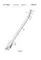
- FIG. 1is a perspective view of a preferred embodiment of cannula 100 showing retractor 112 in an extended position.
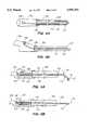
- FIG. 2ais a cut-away side view of retractor 112 and cannula 100.
- FIG. 2bis a top view of retractor 112.
- FIG. 3ais a perspective side view of cannula 100 with a saphenous vein positioned within the cradle 116.
- FIG. 3bis a perspective side view of the distal end 122 of cannula 100 in an embodiment in which an endoscope 126 and a surgical tool 120 are present and partially extended.
- FIG. 3cis a front view of the distal end 122 of cannula 100 in which the surgical tool 120 and the retractor 116 are partially extended, and an endoscope 126 is present.
- FIG. 4ais a cut-away top view of cannula 100.
- FIG. 4bis a cut-away side view of cannula 100.
- FIG. 5ais a cut-away view of a sliding tube embodiment of cannula 100 in a first position.
- FIG. 5bis a cut-away view of the sliding tube embodiment of FIG. 5a in a second position.
- FIG. 6ais a cut-away view of an embodiment of cannula 100 having an angling device 140.
- FIG. 6bis a cut-away side view of the apparatus illustrated in FIG. 6a in which the retractor 112 is extended and the angling device 140 is actuated.
- FIG. 6cis a cut-away side view of the angling device embodiment in which the angling device 140 is in a separate lumen from the retractor 112.
- FIG. 7ais a cut-away side view of a twistable retractor 112 in a straight position.
- FIG. 7bis a side view of the retractor 112 of FIG. 7a.
- FIG. 7cis a cut-away side view of twistable retractor 112 in a crossed position.
- FIG. 7dis a side view of the retractor 112 of FIG. 7c.
- FIG. 8ais a cut-away side view of the handle 104.
- FIG. 8bis a cut-away side view of an alternate embodiment of handle 104.
- FIG. 9ais a side view of cradle 116.
- FIG. 9billustrates a first alternate embodiment of cradle 116.
- FIG. 9cillustrates multiple views of a second alternate embodiment of cradle 116.
- FIG. 9dillustrates multiple views of a third alternate embodiment of cradle 116.
- FIG. 9eillustrates multiple views of a fourth alternate embodiment of cradle 116.
- FIG. 9fillustrates multiple views of a fifth alternate embodiment of cradle 116.
- FIG. 9gillustrates multiple views of an embodiment of cradle 116 having a spur.
- FIG. 10aillustrates a top view of an embodiment of the cradle 116 of FIG. 9c without a "C" ring.
- FIG. 10billustrates a side view of the cradle 116 of FIG. 10a.
- Figure 10cillustrates a top view of the cradle 116 of FIG. 9c with the "C" ring attached.
- FIG. 10dillustrates a side view of the cradle 116 of FIG. 10c.
- FIG. 1illustrates a perspective view of a preferred embodiment of cannula 100 showing retractor 112 in an extended position.
- Cannula 100includes an outer housing 102 of bioinert material such as polymed UD that may be approximately 12" to 18" in length.
- the proximal end of the cannula 100is disposed in handle 104 that includes a button 106 which is coupled to retractor 112 for controlling the translational movement of retractor 112, as described in more detail below.
- FIG. 2aillustrates the retractor 112 in more detail.
- retractor 112is formed of resilient wire which has a smooth bend intermediate to a first portion 110 and a second portion 114 of the retractor.
- the retractor 112is described as having two portions for ease of description, although the retractor 112 may be formed as an integrated structure. However, retractor 112 may also be manufactured from two separate portions 110, 114 that are coupled together.
- the first portion 110 of the retractor 112is positioned within the cannula 100 with the axis 111 of the first portion 110 approximately parallel to the axis 101 of the cannula 100.
- the second portion 114is positioned to bend away from the central axis 101 of the cannula.
- the angle 117 of displacement between the axis 115 of the second portion and the central axis 101 of cannula 100may be any angle from zero to 180 degrees.
- the second portion 114includes a dissection cradle 116 at the distal end of the second portion 114.
- the retractor 112may be formed of bioinert material such as stainless steel, or a polymer such as nylon or polyetherimide, or other appropriately strong and springy plastic. In one embodiment, the retractor 112 includes a coating for lubrication, insulation, and low visual glare using, for example, parylene or nylon 11.
- FIG. 2billustrates the retractor 112 formed with two legs.
- the legs 141, 142 of the retractor 112 at the distal endform the dissection cradle 116 in a loop or "U" shape, as shown in FIG. 2a.
- the top portion 144 of the U-shaped bendis preferably flattened to provide additional surface area for atraumatically supporting a vein 118 or vessel of interest.
- the side arches 128 of the dissection cradle 116are used for skeletonizing or dissecting the vein from the surrounding tissues, as well as acting as walls to keep the vessel captured within the arch.
- the several embodiments of dissection cradle 116are described in more detail below.
- FIG. 3aillustrates a perspective view of the cannula 100 in accordance with the present invention with the retractor fully extended, holding a saphenous vein 118, and also illustrates an external surgical tool 120 disposed adjacent the cannula 100 for performing a surgical operation, for example, severing a tributary or side branch of the vein 118.
- the veinis positioned within the side arches 128 of the cradle 116.
- the dissection cradle 116may be used to cradle a vein, vessel, tissue or organ of interest, and surgical tool 120 may be any surgical tool suitable for performing a surgical procedure near the dissection cradle 116.
- FIG. 3billustrates a perspective view of cannula 100 in an embodiment in which the surgical tool 120 is positioned within the cannula 100, and an endoscope 126 is present.
- cradle 116preferably overlays the endoscope 126 with sufficient clearance to facilitate relative movements thereof.
- the endoscopemay also be located adjacent the surgical tool 120.
- endoscope 126is positioned with cannula 100 to allow a clear field of view upon extension of the retractor 112.
- Surgical tool 120is illustrated as scissors, used to sever a tributary or side branch of a saphenous vein 118. In this embodiment, surgical tool 120 is maximally displaced from the cradle 116 at the cannula end 122.
- the "U"-shaped loop 129 of the cradle 116is closest to the surgical tool 120. This ensures that a vein 118 or other tissue of interest is retracted away from the surgical tool 120 to facilitate manipulating the surgical tool 120 relative to the side branch or other tissue.
- FIG. 4ais a cut-away top view of cannula 100.
- the retractor 112is slidably positioned within minor lumens 113 along the length of the cannula 100 within close tolerances in order to position the retractor 112 stably within the cannula 100.
- retractor legs 141, 142are approximately 0.045 inches in diameter and the lumens 113 encasing the legs 141, 142 are approximately 0.080 inches in diameter, as friction between the legs of the retractor 112 and the lumens 113 holds the retractor stably within the cannula.
- This configurationrestricts rotational movement of the retractor to provide more stable retraction as compared with conventional retractors.
- the legs 141, 142 of the retractor 112are formed of flexible, resilient material and are retained within the lumen 113 in substantially straight or flat orientation, but may return to a material bend or curve, as illustrated in FIG. 5a, as the retractor 112 is extended from the distal end of the cannula 100.
- the leg 141 of the retractor 112passes through a sliding gas or fluid seal 130 at the proximal end of the lumen 113.
- the leg 141 of the retractor 112passes out of the cannula 100 and into handle 104 for attachment to a slider button 106 for facilitating translational movement of the retractor 112 from the proximal or handle end of the cannula 100.
- other types of control devicessuch as knobs, grips, finger pads, and the like may be linked in conventional ways to the retractor 112 in order to manually control the translational movement of retractor 112.
- the proximal end of leg 141is bent relative to the axis of the cannula, and the button 106 is attached to the bent position of the leg 141 to facilitate moving the button 106 and the retractor 112 translationally under manual control.
- the button 106preferably includes lateral grooves to prevent finger or thumb slippage during sliding manipulation of the retractor 112.
- a useractuates the slider button 106 to extend retractor 112 out of the lumen 113 at the distal end of the cannula 100.
- the resilient retractor 112is formed in a smooth bend, as shown in FIG. 2a, and gradually deflects away from the central axis 101 of the cannula 100 as the retractor is extended.
- the vesselUpon encountering the target vessel or tissue of interest, the vessel is restrained in the cradle 116, and a lateral resilient force is exerted on the target vessel in a direction away from the cannula.
- the vesselis thus pushed away from the axis of the cannula 100, isolating it from surrounding tissue or adjacent vessels such as tributaries or side branches.
- a surgical tool 120such as cauterizing scissors may be safely employed to operate on the tributary without harming the saphenous vein 118.
- the retractor 112is again resiliently straightened or flattened.
- a sliding tube 132is added to provide operational versatility to cannula 100.
- the sliding tube 132In a first position, the sliding tube 132 is retracted and the retractor 112 protrudes from the distal end at an angle with respect to the central axis 101 of the cannula 100.
- the sliding tube 132In a second position, the sliding tube 132 is extended out, temporarily straightening the retractor 112.
- a sliding tube 132in a first position encases the retractor 112 up to the point at which the retractor 112 curves away from the central axis 101 of the cannula thus allowing the retractor 112 to displace and isolate a target vessel.
- the proximal end of the sliding tube 132is linked to button 107 for translationally moving retractor 112 as well as actuating the sliding tube 132.
- the sliding tube 132is in a first position with the button 107 in an upright position.
- a spring 134is coupled between a support structure 135 and the proximal end 137 of the sliding tube 132. In the first position of sliding tube 132, the spring 134 is extended fully and exerts little or no force on the sliding tube 132.
- sliding tube 132may be manually manipulated without linkage to a button 107.
- button 107is pushed down. As illustrated in FIG. 5b, the button 107 has a cam surface 136 which pushes on the proximal end 137 of the sliding tube 132 as the button 107 is pressed.
- the sliding tube 132is pushed forward, overcoming the resilient force of spring 134, to encase the retractor 112 and decrease angle 117 between the distal end of the retractor 112 and the central axis 101 of the cannula 100.
- the spring forceurges the proximal end 137 of the sliding tube 132 back toward the first position against button 107.
- the sliding tube 132is formed of material having sufficient strength to force the retractor 112 to straighten out the angle 117, and the retractor 112 is formed of resilient material having a sufficient flexibility to straighten out the angle 117 in response to a tube 132 being slid over the retractor 112, but having sufficient rigidity to cradle and dissect a target vessel. Resiliency of the retractor 112 ensures return to the downwardly-curved shape after being released from tube 132.
- a manual actuatormay be configured in other ways than button 107 to extend the sliding tube 132 in response, for example, to being pulled up instead of pushed down.
- FIGS. 6a and 6bAnother embodiment employs a retractor 112 which has a naturally straight shape.
- an angling device 140is disposed between the distal end of the retractor 112 and the proximal end of the cannula.
- the angling device 140may be positioned within the same lumens 113 as the retractor 112 and preferably may comprise two wires coupled to points below the cradle 116 of the retractor 112 substantially in parallel positions on each of the legs 141, 142.
- the angling device 140Upon extending the retractor 112 using button 106, the angling device 140 is extended with the retractor 112.
- the angling device 140is coupled to a handle 145 at the proximal end of the cannula 100 to facilitate establishing an angle in the retractor 112 by pulling with a backward force on the angling device 140.
- the angling device 140is actuated and a bend is created in the retractor 112 as the backward force exerted on the distal end of the retractor is exerted against the relatively fixed position of the retractor legs 141, 142 disposed within the lumens 113.
- the angling device 140may also be located in a separate lumen 202 from the retractor 112 with part of the angling device 140 positioned outside of the cannula 100 when the retractor 112 is in the retracted position.
- FIG. 7aillustrates another embodiment of cannula 100 in which the retractor 112 is pre-formed with one leg 141 of the retractor 112 bent at an angle at its proximal end skewed to the axis of the distal end of the other leg 142.
- the bent portion of the leg 141may be linked to a sliding knob 147 for convenient manual manipulation of this embodiment of the invention.
- the knob 147Upon sliding the knob 147, the leg 142 coupled to knob 147 is twisted rotationally.
- the two legs 141, 142 of retractor 112are coupled together via cradle 116.
- the axis of the second portion of the retractor 112 in the first positionis at a first angle 117 to the axis of the cannula 100, as shown in FIG. 7b.
- leg 141is rotated and crosses under leg 142, as shown in FIG. 7c. This causes cradle 116 to flip 180 degrees and bends the retractor 112 at a second angle 119, as shown in FIG. 7d.
- the vesselis transported to the other side of the cannula 100. This allows the user to isolate the vessel by simply actuating knob 147.
- FIG. 8aillustrates a cut-away side view of button 106 on the handle 104 of cannula 100, with an endoscope 126 positioned within cannula 100.
- button 106is coupled to one leg 141 of the proximal end of retractor 112. Sliding the button 106 in groove 146 translationally moves the retractor 112. Groove 146 is preferably minimally wider than the shaft of button 106 to minimize excessive horizontal movement of button 106 while still allowing smooth translational movement of button 106.
- the button 106may include locking or ratcheting teeth 152 to give tactile feedback of its location, and to positively retain the button and the associated leg 141 in an extended or retracted position.
- button 106Several mating teeth 148 are located underneath groove 146, and a spring member 150 is attached to button 106 to exert pressure against the base of groove 146, to engage mating teeth 148, 152.
- a forceis applied on the top of button 106, the interlocking sets of teeth are disengaged and button 106 can move freely.
- button 106is released and is retained place by the engaged teeth 148, 152.
- FIG. 9aillustrates a top view of cradle 116 in an embodiment in which the cradle 116 is formed by two legs 141, 142 of retractor 112.
- the distal end of the legsform "U"-shaped side guides.
- the top 144 of the distal portion of the "U”is preferably flattened. This provides atraumatic support for the target vessel retained within cradle 116. Additionally, by minimizing the thickness of distal portion 144, contact with other devices in close proximity with retractor 112 is minimized.
- the cradle 116may have other effective shapes, for example, as illustrated in FIG. 9b in which a "C" ring element is attached to legs of the cradle 116.
- the "C" ringmay have a small hole 200 in one side with an axis approximately parallel to the axis of the retractor 112. This hole 200 is used to hold suture or other ligating materials, and may also be used as a knot pusher.
- FIGS. 10a and 10bin an alternate embodiment of the embodiment of FIG.
- the retractor 112is formed and flattened and a "C"-shaped ring is coupled to the reactor 112 by, for example, gluing or molding the "C" ring to the distal end of the retractor 112, as shown in FIG. 10c and 10d.
- the side guides of the cradlemay include a loop 129 in a "V" shape, an arced "U” shape, or a semi-circular shape.
- the retractor 112has only one leg 141, and the cradle 116 is formed by the leg 141.
- a stopper 160is coupled to the end of the leg 141 to serve as a guide to retain the target vessel, and add a blunt surface to the end of the wire, for example, for pushing and probing tissue.
- 9gillustrates a retractor 112 having a spur 204 formed in one or both legs 141, 142 for allowing the retractor 112 to be used for dissection.
- Sinusoidal, half-sinusoidal, and other geometric configurationsmay be used equally effectively as the shape of loop 129 in accordance with the present invention.
Landscapes
- Health & Medical Sciences (AREA)
- Life Sciences & Earth Sciences (AREA)
- Surgery (AREA)
- Animal Behavior & Ethology (AREA)
- Public Health (AREA)
- Engineering & Computer Science (AREA)
- Biomedical Technology (AREA)
- Heart & Thoracic Surgery (AREA)
- Medical Informatics (AREA)
- Molecular Biology (AREA)
- Veterinary Medicine (AREA)
- General Health & Medical Sciences (AREA)
- Nuclear Medicine, Radiotherapy & Molecular Imaging (AREA)
- Rheumatology (AREA)
- Physics & Mathematics (AREA)
- Biophysics (AREA)
- Optics & Photonics (AREA)
- Pathology (AREA)
- Radiology & Medical Imaging (AREA)
- Surgical Instruments (AREA)
Abstract
Description
Claims (2)
Priority Applications (21)
| Application Number | Priority Date | Filing Date | Title |
|---|---|---|---|
| US09/102,723US5895353A (en) | 1998-06-22 | 1998-06-22 | Vessel isolating retractor cannula and method |
| US09/200,218US6162173A (en) | 1998-06-22 | 1998-11-25 | Device and method for remote vessel ligation |
| US09/200,177US5993384A (en) | 1998-06-22 | 1998-11-25 | Vessel isolating retractor cannula and method |
| US09/227,244US6176825B1 (en) | 1998-06-22 | 1999-01-08 | Cannula-based irrigation system and method |
| AU35034/99AAU3503499A (en) | 1998-06-22 | 1999-06-15 | Vessel isolating retractor cannula and method |
| EP99111742AEP0980673A3 (en) | 1998-06-22 | 1999-06-17 | Vessel isolating retractor cannula and method |
| JP11172954AJP2000037389A (en) | 1998-06-22 | 1999-06-18 | Blood vessel separating tractor cannula and method |
| US09/521,279US6348037B1 (en) | 1998-06-22 | 2000-03-07 | Device and method for remote vessel ligation |
| US09/634,132US6406425B1 (en) | 1998-06-22 | 2000-08-08 | Cannula-based irrigation system and method |
| US10/052,016US6830546B1 (en) | 1998-06-22 | 2002-01-16 | Device and method for remote vessel ligation |
| US10/174,404US20020183593A1 (en) | 1998-06-22 | 2002-06-17 | Cannula-based surgical instrument and method |
| US10/218,475US6752756B2 (en) | 1998-06-22 | 2002-08-12 | Combined vessel dissection and transection device and method |
| US10/773,770US6976957B1 (en) | 1998-06-22 | 2004-02-06 | Cannula-based surgical instrument and method |
| US10/807,368US7326178B1 (en) | 1998-06-22 | 2004-03-22 | Vessel retraction device and method |
| US10/897,157US7972265B1 (en) | 1998-06-22 | 2004-07-21 | Device and method for remote vessel ligation |
| US10/925,536US7476198B1 (en) | 1998-06-22 | 2004-08-24 | Cannula-based surgical instrument |
| US11/969,318US8241210B2 (en) | 1998-06-22 | 2008-01-04 | Vessel retractor |
| US12/333,542US7867163B2 (en) | 1998-06-22 | 2008-12-12 | Instrument and method for remotely manipulating a tissue structure |
| US12/983,867US20120010463A1 (en) | 1998-06-22 | 2011-01-03 | Instrument and method for remotely manipulating a tissue structure |
| US13/417,161US20130072758A1 (en) | 1998-06-22 | 2012-03-09 | Vessel retractor |
| US14/139,782US20140343367A1 (en) | 1998-06-22 | 2013-12-23 | Vessel retractor |
Applications Claiming Priority (1)
| Application Number | Priority Date | Filing Date | Title |
|---|---|---|---|
| US09/102,723US5895353A (en) | 1998-06-22 | 1998-06-22 | Vessel isolating retractor cannula and method |
Related Child Applications (4)
| Application Number | Title | Priority Date | Filing Date |
|---|---|---|---|
| US09/200,177ContinuationUS5993384A (en) | 1998-06-22 | 1998-11-25 | Vessel isolating retractor cannula and method |
| US09/200,218Continuation-In-PartUS6162173A (en) | 1998-06-22 | 1998-11-25 | Device and method for remote vessel ligation |
| US09/227,244Continuation-In-PartUS6176825B1 (en) | 1998-06-22 | 1999-01-08 | Cannula-based irrigation system and method |
| US22739399AContinuation-In-Part | 1998-06-22 | 1999-01-08 |
Publications (1)
| Publication Number | Publication Date |
|---|---|
| US5895353Atrue US5895353A (en) | 1999-04-20 |
Family
ID=22291360
Family Applications (2)
| Application Number | Title | Priority Date | Filing Date |
|---|---|---|---|
| US09/102,723Expired - LifetimeUS5895353A (en) | 1998-06-22 | 1998-06-22 | Vessel isolating retractor cannula and method |
| US09/200,177Expired - LifetimeUS5993384A (en) | 1998-06-22 | 1998-11-25 | Vessel isolating retractor cannula and method |
Family Applications After (1)
| Application Number | Title | Priority Date | Filing Date |
|---|---|---|---|
| US09/200,177Expired - LifetimeUS5993384A (en) | 1998-06-22 | 1998-11-25 | Vessel isolating retractor cannula and method |
Country Status (4)
| Country | Link |
|---|---|
| US (2) | US5895353A (en) |
| EP (1) | EP0980673A3 (en) |
| JP (1) | JP2000037389A (en) |
| AU (1) | AU3503499A (en) |
Cited By (50)
| Publication number | Priority date | Publication date | Assignee | Title |
|---|---|---|---|---|
| WO2000040160A2 (en) | 1999-01-08 | 2000-07-13 | Origin Medsystems, Inc. | Combined vessel dissection and transection device and method |
| DE19926555A1 (en)* | 1999-06-11 | 2000-12-28 | Storz Karl Gmbh & Co Kg | Medical gripping instrument and method for using this gripping instrument |
| US6406425B1 (en)* | 1998-06-22 | 2002-06-18 | Origin Medasystems | Cannula-based irrigation system and method |
| US6592559B1 (en) | 1998-12-09 | 2003-07-15 | Cook Incorporated | Hollow, curved, superlastic medical needle |
| US6666832B1 (en)* | 2002-01-07 | 2003-12-23 | Cardica, Inc. | Surgical measurement tool |
| US20040194729A1 (en)* | 2003-04-04 | 2004-10-07 | Dunn Steven B | Shedding blade with adjustable blade length |
| US20040204725A1 (en)* | 2001-06-26 | 2004-10-14 | Bayer Hanspeter Robert | Conduit harvesting instrument and method |
| US6830546B1 (en) | 1998-06-22 | 2004-12-14 | Origin Medsystems, Inc. | Device and method for remote vessel ligation |
| US20050064616A1 (en)* | 2003-09-23 | 2005-03-24 | Been-Yih Jin | Semiconductor channel on insulator structure |
| US20050096671A1 (en)* | 2003-10-31 | 2005-05-05 | Parris Wellman | Control mechanism for a surgical instrument |
| US20050096646A1 (en)* | 2003-10-31 | 2005-05-05 | Parris Wellman | Surgical system for retracting and severing tissue |
| US20050096677A1 (en)* | 2003-10-31 | 2005-05-05 | Parris Wellman | Space-creating retractor with vessel manipulator |
| US20050096670A1 (en)* | 2003-10-31 | 2005-05-05 | Parris Wellman | Surgical end effector |
| US20050096645A1 (en)* | 2003-10-31 | 2005-05-05 | Parris Wellman | Multitool surgical device |
| US20050148817A1 (en)* | 2003-10-31 | 2005-07-07 | Olympus Corporation | Living-body tissue removing apparatus |
| US20050149094A1 (en)* | 2003-10-31 | 2005-07-07 | Olympus Corporation | Trocar |
| US20050154257A1 (en)* | 2003-10-31 | 2005-07-14 | Olympus Corporation | Living-body tissue removing apparatus |
| US20050159764A1 (en)* | 2003-10-31 | 2005-07-21 | Olympus Corporation | Living-body tissue removing apparatus |
| US20050273125A1 (en)* | 2004-05-13 | 2005-12-08 | Opie John C | Percutaneous vein harvester with shielded blade |
| US20060074444A1 (en)* | 2004-09-28 | 2006-04-06 | Lin Arthur M | Modular vessel harvesting system and method |
| US20060173474A1 (en)* | 2003-10-31 | 2006-08-03 | Parris Wellman | Surgical device having a track to guide an actuator |
| US20060235450A1 (en)* | 2004-09-22 | 2006-10-19 | Olympus Corporation | Living body tissue harvesting apparatus |
| US20060287584A1 (en)* | 2005-06-16 | 2006-12-21 | Javier Garcia-Bengochia | Surgical retractor extensions |
| US20070005084A1 (en)* | 2004-06-16 | 2007-01-04 | Clague Cynthia T | Minimally invasive coring vein harvester |
| US7326178B1 (en) | 1998-06-22 | 2008-02-05 | Origin Medsystems, Inc. | Vessel retraction device and method |
| US20080033472A1 (en)* | 2004-08-17 | 2008-02-07 | Yasuhiro Shimizu | Blood Vessel Ablating Tool |
| US20080161841A1 (en)* | 2006-10-16 | 2008-07-03 | Clague Cynthia T | Cutting device and method of vessel harvesting |
| US20080228194A1 (en)* | 2007-03-13 | 2008-09-18 | Cardiac Pacemakers, Inc. | Method and apparatus for endoscopic access to the vagus nerve |
| US20080306335A1 (en)* | 2006-06-01 | 2008-12-11 | Origin Medsystems, Inc. | Endoscopic vessel harvesting system components |
| US7476198B1 (en) | 1998-06-22 | 2009-01-13 | Maquet Cardiovascular, Llc | Cannula-based surgical instrument |
| US20090306699A1 (en)* | 2008-06-10 | 2009-12-10 | Terumo Cardiovascular Systems Corporation | Blunt Dissector for Separating Blood Vessels from Surrounding Tissue |
| US20100152792A1 (en)* | 2001-07-16 | 2010-06-17 | Spinecore, Inc. | Insertion tool for use with intervertebral spacers |
| US20110046624A1 (en)* | 2009-08-21 | 2011-02-24 | Maquet Cardiovascular Llc | Single handled endoscopic vessel harvesting system with rotation control |
| US7938842B1 (en) | 1998-08-12 | 2011-05-10 | Maquet Cardiovascular Llc | Tissue dissector apparatus |
| US20110172688A1 (en)* | 2010-01-11 | 2011-07-14 | Tyco Healthcare Group Lp | Conduit Harvesting Instrument and Method |
| US7981133B2 (en) | 1995-07-13 | 2011-07-19 | Maquet Cardiovascular, Llc | Tissue dissection method |
| US9119900B2 (en) | 2011-12-23 | 2015-09-01 | Saphena Medical, Inc. | Unitary endoscopic vessel harvesting devices |
| US9498246B2 (en) | 2013-03-14 | 2016-11-22 | Saphena Medical, Inc. | Unitary endoscopic vessel harvesting devices |
| US9814481B2 (en) | 2013-03-14 | 2017-11-14 | Saphena Medical, Inc. | Unitary endoscopic vessel harvesting devices |
| US9943328B2 (en) | 2015-04-28 | 2018-04-17 | Saphena Medical, Inc. | Unitary endoscopic vessel harvesting devices with an elastic force |
| US10064611B2 (en) | 2015-07-22 | 2018-09-04 | Covidien Lp | Methods and devices for vein harvesting |
| EP3391803A1 (en) | 2007-03-22 | 2018-10-24 | Maquet Cardiovascular LLC | Devices for reducing reflection-illuminated artifacts |
| US10363056B2 (en) | 2015-06-17 | 2019-07-30 | Saphena Medical, Inc. | Unitary endoscopic vessel harvesting devices |
| US10507012B2 (en) | 2000-11-17 | 2019-12-17 | Maquet Cardiovascular Llc | Vein harvesting system and method |
| US10575835B2 (en) | 2014-10-14 | 2020-03-03 | Covidien Lp | Methods and devices for vein harvesting |
| US10646210B2 (en) | 2014-10-14 | 2020-05-12 | Covidien Lp | Methods and devices for vein harvesting |
| US10898175B2 (en) | 2016-10-04 | 2021-01-26 | Jgmg Bengochea, Llc | Retractor extension clip systems |
| US11547466B2 (en) | 2018-06-20 | 2023-01-10 | Covidien Lp | Visualization devices and methods for use in surgical procedures |
| WO2024076634A1 (en) | 2022-10-04 | 2024-04-11 | Marizyme, Inc. | Kits and use thereof in surgical procedures for endoscopic harvesting of vessels |
| US12357285B2 (en) | 2019-04-05 | 2025-07-15 | Saphena Medical, Inc. | Unitary device for vessel harvesting and method of using same |
Families Citing this family (16)
| Publication number | Priority date | Publication date | Assignee | Title |
|---|---|---|---|---|
| US6656198B2 (en) | 2001-06-01 | 2003-12-02 | Ethicon-Endo Surgery, Inc. | Trocar with reinforced obturator shaft |
| ATE526883T1 (en) | 2001-12-27 | 2011-10-15 | Olympus Corp | COVER WITH DEVICES FOR ENDOSCOPIC HARVESTING OF BLOOD VESSELS |
| JP3671002B2 (en) | 2001-12-28 | 2005-07-13 | オリンパス株式会社 | Endoscope sheath |
| EP1779789B1 (en)* | 2001-12-28 | 2009-02-25 | Olympus Corporation | Living tissue harvesting apparatus |
| WO2003094754A1 (en)* | 2002-05-09 | 2003-11-20 | Tyco Healthcare Group Lp | Organ retractor and method of using the same |
| AU2003272277A1 (en)* | 2002-09-06 | 2004-03-29 | C.R. Bard, Inc. | Endoscopic accessory mounting adaptor |
| USD480807S1 (en) | 2002-09-06 | 2003-10-14 | C. R. Bard, Inc. | Control handle for a medical device used with an endoscope |
| EP1545325A4 (en) | 2002-09-06 | 2008-02-20 | Conmed Endoscopic Technologies | ENDOSCOPIC BAND LIGATOR |
| US7223230B2 (en)* | 2002-09-06 | 2007-05-29 | C. R. Bard, Inc. | External endoscopic accessory control system |
| CN101528110A (en)* | 2006-03-10 | 2009-09-09 | 利兰斯坦福青年大学托管委员会 | Percutaneous access and visualization of the spine |
| US8202216B2 (en)* | 2007-03-08 | 2012-06-19 | Warsaw Orthopedic, Inc. | Tissue retractor |
| JP4662374B2 (en)* | 2007-03-26 | 2011-03-30 | オリンパス株式会社 | Endoscopic blood vessel collection device |
| JP4755661B2 (en)* | 2008-02-25 | 2011-08-24 | オリンパス株式会社 | Biological tissue collection device |
| US9610072B2 (en)* | 2009-11-02 | 2017-04-04 | Apx Opthalmology Ltd. | Iris retractor |
| US8074859B2 (en) | 2010-03-31 | 2011-12-13 | Tyco Healthcare Group Lp | Surgical instrument |
| CN102834045B (en)* | 2010-07-09 | 2015-03-11 | 奥林巴斯医疗株式会社 | Endoscope-holding device and endoscopic system |
Citations (13)
| Publication number | Priority date | Publication date | Assignee | Title |
|---|---|---|---|---|
| US3313294A (en)* | 1963-09-06 | 1967-04-11 | Uddenberg Goran Olof | Instruments for open-holding of cavity openings in the human body |
| US3857386A (en)* | 1973-08-17 | 1974-12-31 | T Ashbell | Surgical device for holding and retracting skin or bone |
| US4190042A (en)* | 1978-03-16 | 1980-02-26 | Manfred Sinnreich | Surgical retractor for endoscopes |
| US4428746A (en)* | 1981-07-29 | 1984-01-31 | Antonio Mendez | Glaucoma treatment device |
| US4874375A (en)* | 1987-04-13 | 1989-10-17 | Ellison Arthur E | Tissue retractor |
| US5251613A (en)* | 1991-05-06 | 1993-10-12 | Adair Edwin Lloyd | Method of cervical videoscope with detachable camera |
| US5275608A (en)* | 1991-10-16 | 1994-01-04 | Implemed, Inc. | Generic endoscopic instrument |
| US5337736A (en)* | 1992-09-30 | 1994-08-16 | Reddy Pratap K | Method of using a laparoscopic retractor |
| US5450842A (en)* | 1993-02-19 | 1995-09-19 | United States Surgical Corporation | Endoscopic surgical retractor |
| US5501654A (en)* | 1993-07-15 | 1996-03-26 | Ethicon, Inc. | Endoscopic instrument having articulating element |
| US5512037A (en)* | 1994-05-12 | 1996-04-30 | United States Surgical Corporation | Percutaneous surgical retractor |
| US5558620A (en)* | 1993-02-05 | 1996-09-24 | Richard Wolf Gmbh | Medical instrument employing curved spreading members to manipulate organs within the body |
| US5690606A (en)* | 1994-06-20 | 1997-11-25 | Slotman; Gus J. | Tisssue spreading surgical instrument |
Family Cites Families (16)
| Publication number | Priority date | Publication date | Assignee | Title |
|---|---|---|---|---|
| US4744363A (en)* | 1986-07-07 | 1988-05-17 | Hasson Harrith M | Intra-abdominal organ stabilizer, retractor and tissue manipulator |
| US5271385A (en)* | 1990-03-29 | 1993-12-21 | United States Surgical Corporation | Abdominal cavity organ retractor |
| US5601224A (en)* | 1992-10-09 | 1997-02-11 | Ethicon, Inc. | Surgical instrument |
| US5626587A (en)* | 1992-10-09 | 1997-05-06 | Ethicon Endo-Surgery, Inc. | Method for operating a surgical instrument |
| US5662662A (en)* | 1992-10-09 | 1997-09-02 | Ethicon Endo-Surgery, Inc. | Surgical instrument and method |
| US5374277A (en)* | 1992-10-09 | 1994-12-20 | Ethicon, Inc. | Surgical instrument |
| US5370109A (en)* | 1993-02-19 | 1994-12-06 | United States Surgical Corporation | Deformable endoscopic surgical retractor |
| US5339803A (en)* | 1993-04-13 | 1994-08-23 | Ilya Mayzels | Self-hinging disposable retractor instrument for endoscopic surgery |
| WO1995010982A1 (en)* | 1993-10-20 | 1995-04-27 | Correa Marco Aurelio Moura De | Surgical instrument to perform subcutaneous endoscopic surgery |
| US5620458A (en)* | 1994-03-16 | 1997-04-15 | United States Surgical Corporation | Surgical instruments useful for endoscopic spinal procedures |
| US5807376A (en)* | 1994-06-24 | 1998-09-15 | United States Surgical Corporation | Apparatus and method for performing surgical tasks during laparoscopic procedures |
| US5713505A (en)* | 1996-05-13 | 1998-02-03 | Ethicon Endo-Surgery, Inc. | Articulation transmission mechanism for surgical instruments |
| US5704534A (en)* | 1994-12-19 | 1998-01-06 | Ethicon Endo-Surgery, Inc. | Articulation assembly for surgical instruments |
| US5632432A (en)* | 1994-12-19 | 1997-05-27 | Ethicon Endo-Surgery, Inc. | Surgical instrument |
| US5938620A (en)* | 1996-06-05 | 1999-08-17 | Daxer; Albert | Apparatus for testing color discrimination in the human visual system |
| US5702408A (en)* | 1996-07-17 | 1997-12-30 | Ethicon Endo-Surgery, Inc. | Articulating surgical instrument |
- 1998
- 1998-06-22USUS09/102,723patent/US5895353A/ennot_activeExpired - Lifetime
- 1998-11-25USUS09/200,177patent/US5993384A/ennot_activeExpired - Lifetime
- 1999
- 1999-06-15AUAU35034/99Apatent/AU3503499A/ennot_activeAbandoned
- 1999-06-17EPEP99111742Apatent/EP0980673A3/ennot_activeWithdrawn
- 1999-06-18JPJP11172954Apatent/JP2000037389A/enactivePending
Patent Citations (13)
| Publication number | Priority date | Publication date | Assignee | Title |
|---|---|---|---|---|
| US3313294A (en)* | 1963-09-06 | 1967-04-11 | Uddenberg Goran Olof | Instruments for open-holding of cavity openings in the human body |
| US3857386A (en)* | 1973-08-17 | 1974-12-31 | T Ashbell | Surgical device for holding and retracting skin or bone |
| US4190042A (en)* | 1978-03-16 | 1980-02-26 | Manfred Sinnreich | Surgical retractor for endoscopes |
| US4428746A (en)* | 1981-07-29 | 1984-01-31 | Antonio Mendez | Glaucoma treatment device |
| US4874375A (en)* | 1987-04-13 | 1989-10-17 | Ellison Arthur E | Tissue retractor |
| US5251613A (en)* | 1991-05-06 | 1993-10-12 | Adair Edwin Lloyd | Method of cervical videoscope with detachable camera |
| US5275608A (en)* | 1991-10-16 | 1994-01-04 | Implemed, Inc. | Generic endoscopic instrument |
| US5337736A (en)* | 1992-09-30 | 1994-08-16 | Reddy Pratap K | Method of using a laparoscopic retractor |
| US5558620A (en)* | 1993-02-05 | 1996-09-24 | Richard Wolf Gmbh | Medical instrument employing curved spreading members to manipulate organs within the body |
| US5450842A (en)* | 1993-02-19 | 1995-09-19 | United States Surgical Corporation | Endoscopic surgical retractor |
| US5501654A (en)* | 1993-07-15 | 1996-03-26 | Ethicon, Inc. | Endoscopic instrument having articulating element |
| US5512037A (en)* | 1994-05-12 | 1996-04-30 | United States Surgical Corporation | Percutaneous surgical retractor |
| US5690606A (en)* | 1994-06-20 | 1997-11-25 | Slotman; Gus J. | Tisssue spreading surgical instrument |
Cited By (96)
| Publication number | Priority date | Publication date | Assignee | Title |
|---|---|---|---|---|
| US7981133B2 (en) | 1995-07-13 | 2011-07-19 | Maquet Cardiovascular, Llc | Tissue dissection method |
| US8241210B2 (en) | 1998-06-22 | 2012-08-14 | Maquet Cardiovascular Llc | Vessel retractor |
| US6830546B1 (en) | 1998-06-22 | 2004-12-14 | Origin Medsystems, Inc. | Device and method for remote vessel ligation |
| US7972265B1 (en)* | 1998-06-22 | 2011-07-05 | Maquet Cardiovascular, Llc | Device and method for remote vessel ligation |
| US7476198B1 (en) | 1998-06-22 | 2009-01-13 | Maquet Cardiovascular, Llc | Cannula-based surgical instrument |
| US6406425B1 (en)* | 1998-06-22 | 2002-06-18 | Origin Medasystems | Cannula-based irrigation system and method |
| US7867163B2 (en) | 1998-06-22 | 2011-01-11 | Maquet Cardiovascular Llc | Instrument and method for remotely manipulating a tissue structure |
| US6752756B2 (en) | 1998-06-22 | 2004-06-22 | Origin Medsystems, Inc. | Combined vessel dissection and transection device and method |
| US7326178B1 (en) | 1998-06-22 | 2008-02-05 | Origin Medsystems, Inc. | Vessel retraction device and method |
| US9700398B2 (en) | 1998-08-12 | 2017-07-11 | Maquet Cardiovascular Llc | Vessel harvester |
| US9730782B2 (en) | 1998-08-12 | 2017-08-15 | Maquet Cardiovascular Llc | Vessel harvester |
| US8460331B2 (en) | 1998-08-12 | 2013-06-11 | Maquet Cardiovascular, Llc | Tissue dissector apparatus and method |
| US7938842B1 (en) | 1998-08-12 | 2011-05-10 | Maquet Cardiovascular Llc | Tissue dissector apparatus |
| US8986335B2 (en) | 1998-08-12 | 2015-03-24 | Maquet Cardiovascular Llc | Tissue dissector apparatus and method |
| US6592559B1 (en) | 1998-12-09 | 2003-07-15 | Cook Incorporated | Hollow, curved, superlastic medical needle |
| WO2000040160A2 (en) | 1999-01-08 | 2000-07-13 | Origin Medsystems, Inc. | Combined vessel dissection and transection device and method |
| DE19926555A1 (en)* | 1999-06-11 | 2000-12-28 | Storz Karl Gmbh & Co Kg | Medical gripping instrument and method for using this gripping instrument |
| US6730109B2 (en) | 1999-06-11 | 2004-05-04 | Karl Storz Gmbh & Co. Kg | Medical gripping instrument and method for using this medical gripping instrument |
| US10507012B2 (en) | 2000-11-17 | 2019-12-17 | Maquet Cardiovascular Llc | Vein harvesting system and method |
| US7699861B2 (en) | 2001-06-26 | 2010-04-20 | Tyco Healthcare Group Lp | Conduit harvesting instrument and method |
| US7645289B2 (en) | 2001-06-26 | 2010-01-12 | Tyco Healthcare Group Lp | Conduit harvesting instrument and method |
| US20040204725A1 (en)* | 2001-06-26 | 2004-10-14 | Bayer Hanspeter Robert | Conduit harvesting instrument and method |
| US20100152792A1 (en)* | 2001-07-16 | 2010-06-17 | Spinecore, Inc. | Insertion tool for use with intervertebral spacers |
| US8348958B2 (en)* | 2001-07-16 | 2013-01-08 | Spinecore, Inc. | Insertion tool for use with intervertebral spacers |
| US7014618B2 (en) | 2002-01-07 | 2006-03-21 | Cardica, Inc. | Surgical measurement tool |
| US20040097835A1 (en)* | 2002-01-07 | 2004-05-20 | Cardica, Inc. | Surgical measurement tool |
| US6666832B1 (en)* | 2002-01-07 | 2003-12-23 | Cardica, Inc. | Surgical measurement tool |
| US7587992B2 (en)* | 2003-04-04 | 2009-09-15 | Munchkin, Inc. | Shedding blade with adjustable blade length |
| US20040194729A1 (en)* | 2003-04-04 | 2004-10-07 | Dunn Steven B | Shedding blade with adjustable blade length |
| US20050064616A1 (en)* | 2003-09-23 | 2005-03-24 | Been-Yih Jin | Semiconductor channel on insulator structure |
| US20050096671A1 (en)* | 2003-10-31 | 2005-05-05 | Parris Wellman | Control mechanism for a surgical instrument |
| US7662164B2 (en) | 2003-10-31 | 2010-02-16 | Olympus Corporation | Living-body tissue removing apparatus |
| US7331971B2 (en) | 2003-10-31 | 2008-02-19 | Olympus Corporation | Living-body tissue removing apparatus |
| US7314479B2 (en) | 2003-10-31 | 2008-01-01 | Parris Wellman | Space-creating retractor with vessel manipulator |
| US20050096646A1 (en)* | 2003-10-31 | 2005-05-05 | Parris Wellman | Surgical system for retracting and severing tissue |
| US20050096677A1 (en)* | 2003-10-31 | 2005-05-05 | Parris Wellman | Space-creating retractor with vessel manipulator |
| US20060173474A1 (en)* | 2003-10-31 | 2006-08-03 | Parris Wellman | Surgical device having a track to guide an actuator |
| US20050096670A1 (en)* | 2003-10-31 | 2005-05-05 | Parris Wellman | Surgical end effector |
| US20050159764A1 (en)* | 2003-10-31 | 2005-07-21 | Olympus Corporation | Living-body tissue removing apparatus |
| US20050154257A1 (en)* | 2003-10-31 | 2005-07-14 | Olympus Corporation | Living-body tissue removing apparatus |
| US8105231B2 (en)* | 2003-10-31 | 2012-01-31 | Olympus Corporation | Living-body tissue removing apparatus |
| US20050149094A1 (en)* | 2003-10-31 | 2005-07-07 | Olympus Corporation | Trocar |
| US20050148817A1 (en)* | 2003-10-31 | 2005-07-07 | Olympus Corporation | Living-body tissue removing apparatus |
| US20050096645A1 (en)* | 2003-10-31 | 2005-05-05 | Parris Wellman | Multitool surgical device |
| US20050273125A1 (en)* | 2004-05-13 | 2005-12-08 | Opie John C | Percutaneous vein harvester with shielded blade |
| US20100305594A1 (en)* | 2004-05-13 | 2010-12-02 | Scottsdale Medical Devices, Inc. | Percutaneous vein harvester with shielded blade |
| US20070005084A1 (en)* | 2004-06-16 | 2007-01-04 | Clague Cynthia T | Minimally invasive coring vein harvester |
| US8480696B2 (en) | 2004-06-16 | 2013-07-09 | Medtronic, Inc. | Minimally invasive coring vein harvester |
| US20080033472A1 (en)* | 2004-08-17 | 2008-02-07 | Yasuhiro Shimizu | Blood Vessel Ablating Tool |
| US20060235450A1 (en)* | 2004-09-22 | 2006-10-19 | Olympus Corporation | Living body tissue harvesting apparatus |
| US8016821B2 (en) | 2004-09-22 | 2011-09-13 | Olympus Corporation | Living body tissue harvesting apparatus |
| US20070185481A1 (en)* | 2004-09-22 | 2007-08-09 | Olympus Corporation | Living body tissue harvesting apparatus |
| US20060074444A1 (en)* | 2004-09-28 | 2006-04-06 | Lin Arthur M | Modular vessel harvesting system and method |
| US7887558B2 (en)* | 2004-09-28 | 2011-02-15 | Maquet Cardiovascular Llc | Modular vessel harvesting system and method |
| US8906048B2 (en) | 2004-09-28 | 2014-12-09 | Maquet Cardiovascular Llc | Modular vessel harvesting system and method |
| US8048109B2 (en) | 2005-06-16 | 2011-11-01 | Javier Garcia-Bengochea | Surgical retractor extensions |
| US20100105985A1 (en)* | 2005-06-16 | 2010-04-29 | Javier Garcia-Bengochea | Surgical retractor extensions |
| US20060287584A1 (en)* | 2005-06-16 | 2006-12-21 | Javier Garcia-Bengochia | Surgical retractor extensions |
| US20100113881A1 (en)* | 2005-06-16 | 2010-05-06 | Javier Garcia-Bengochea | Surgical retractor extensions |
| US11134835B2 (en) | 2006-06-01 | 2021-10-05 | Maquet Cardiovascular Llc | Endoscopic vessel harvesting system components |
| US10299770B2 (en) | 2006-06-01 | 2019-05-28 | Maquet Cardiovascular Llc | Endoscopic vessel harvesting system components |
| US9770230B2 (en) | 2006-06-01 | 2017-09-26 | Maquet Cardiovascular Llc | Endoscopic vessel harvesting system components |
| US11141055B2 (en) | 2006-06-01 | 2021-10-12 | Maquet Cardiovascular Llc | Endoscopic vessel harvesting system components |
| US20080306335A1 (en)* | 2006-06-01 | 2008-12-11 | Origin Medsystems, Inc. | Endoscopic vessel harvesting system components |
| US20080161843A1 (en)* | 2006-10-16 | 2008-07-03 | Clague Cynthia T | Vessel support device and method of vessel harvesting |
| US20100121362A1 (en)* | 2006-10-16 | 2010-05-13 | Scottsdale Medical Devices, Inc. | Vessel support device and method of vessel harvesting |
| US20100114136A1 (en)* | 2006-10-16 | 2010-05-06 | Scottsdale Medical Devices, Inc. | Cutting device and method of vessel harvesting |
| US20080161841A1 (en)* | 2006-10-16 | 2008-07-03 | Clague Cynthia T | Cutting device and method of vessel harvesting |
| US20080167669A1 (en)* | 2006-10-16 | 2008-07-10 | Clague Cynthia T | Vessel tensioning handle and method of vessel harvesting |
| US7819883B2 (en) | 2007-03-13 | 2010-10-26 | Cardiac Pacemakers, Inc. | Method and apparatus for endoscopic access to the vagus nerve |
| US20080228194A1 (en)* | 2007-03-13 | 2008-09-18 | Cardiac Pacemakers, Inc. | Method and apparatus for endoscopic access to the vagus nerve |
| EP3391803A1 (en) | 2007-03-22 | 2018-10-24 | Maquet Cardiovascular LLC | Devices for reducing reflection-illuminated artifacts |
| US20090306699A1 (en)* | 2008-06-10 | 2009-12-10 | Terumo Cardiovascular Systems Corporation | Blunt Dissector for Separating Blood Vessels from Surrounding Tissue |
| US8048100B2 (en) | 2008-06-10 | 2011-11-01 | Terumo Cardiovascular Systems, Corp. | Blunt dissector for separating blood vessels from surrounding tissue |
| EP2133027A2 (en) | 2008-06-10 | 2009-12-16 | Terumo Cardiovascular Systems Corporation | Blunt Dissector for Separating Blood Vessels from Surrounding Tissue |
| US20110046624A1 (en)* | 2009-08-21 | 2011-02-24 | Maquet Cardiovascular Llc | Single handled endoscopic vessel harvesting system with rotation control |
| US8657818B2 (en) | 2009-08-21 | 2014-02-25 | Maquet Cardiovascular Llc | Single handled endoscopic vessel harvesting system with rotation control |
| US20110172688A1 (en)* | 2010-01-11 | 2011-07-14 | Tyco Healthcare Group Lp | Conduit Harvesting Instrument and Method |
| US9119900B2 (en) | 2011-12-23 | 2015-09-01 | Saphena Medical, Inc. | Unitary endoscopic vessel harvesting devices |
| US12064134B2 (en) | 2013-03-14 | 2024-08-20 | Saphena Medical, Inc. | Unitary endoscopic vessel harvesting devices |
| US11751896B2 (en) | 2013-03-14 | 2023-09-12 | Saphena Medical, Inc. | Unitary endoscopic vessel harvesting devices |
| US9814481B2 (en) | 2013-03-14 | 2017-11-14 | Saphena Medical, Inc. | Unitary endoscopic vessel harvesting devices |
| US10537353B2 (en) | 2013-03-14 | 2020-01-21 | Saphena Medical, Inc. | Unitary endoscopic vessel harvesting devices |
| US9498246B2 (en) | 2013-03-14 | 2016-11-22 | Saphena Medical, Inc. | Unitary endoscopic vessel harvesting devices |
| US10575835B2 (en) | 2014-10-14 | 2020-03-03 | Covidien Lp | Methods and devices for vein harvesting |
| US10646210B2 (en) | 2014-10-14 | 2020-05-12 | Covidien Lp | Methods and devices for vein harvesting |
| US11571193B2 (en) | 2014-10-14 | 2023-02-07 | Covidien LLP | Methods and devices for vein harvesting |
| US9943328B2 (en) | 2015-04-28 | 2018-04-17 | Saphena Medical, Inc. | Unitary endoscopic vessel harvesting devices with an elastic force |
| US10874415B2 (en) | 2015-06-17 | 2020-12-29 | Saphena Medical, Inc. | Unitary endoscopic vessel harvesting devices |
| US10363056B2 (en) | 2015-06-17 | 2019-07-30 | Saphena Medical, Inc. | Unitary endoscopic vessel harvesting devices |
| US10064611B2 (en) | 2015-07-22 | 2018-09-04 | Covidien Lp | Methods and devices for vein harvesting |
| US10898175B2 (en) | 2016-10-04 | 2021-01-26 | Jgmg Bengochea, Llc | Retractor extension clip systems |
| US11844505B2 (en) | 2017-02-21 | 2023-12-19 | Jgmg Bengochea, Llc | Retractor extension clip systems and methods |
| US11547466B2 (en) | 2018-06-20 | 2023-01-10 | Covidien Lp | Visualization devices and methods for use in surgical procedures |
| US12357285B2 (en) | 2019-04-05 | 2025-07-15 | Saphena Medical, Inc. | Unitary device for vessel harvesting and method of using same |
| WO2024076634A1 (en) | 2022-10-04 | 2024-04-11 | Marizyme, Inc. | Kits and use thereof in surgical procedures for endoscopic harvesting of vessels |
Also Published As
| Publication number | Publication date |
|---|---|
| US5993384A (en) | 1999-11-30 |
| EP0980673A3 (en) | 2000-03-01 |
| JP2000037389A (en) | 2000-02-08 |
| EP0980673A2 (en) | 2000-02-23 |
| AU3503499A (en) | 2000-01-06 |
Similar Documents
| Publication | Publication Date | Title |
|---|---|---|
| US5895353A (en) | Vessel isolating retractor cannula and method | |
| US7476198B1 (en) | Cannula-based surgical instrument | |
| US7972265B1 (en) | Device and method for remote vessel ligation | |
| US6406425B1 (en) | Cannula-based irrigation system and method | |
| US8241210B2 (en) | Vessel retractor | |
| US6176825B1 (en) | Cannula-based irrigation system and method | |
| US6162173A (en) | Device and method for remote vessel ligation | |
| US6752756B2 (en) | Combined vessel dissection and transection device and method | |
| JP6906063B2 (en) | Catheter insertion device | |
| JP5139979B2 (en) | Surgical instrument guide device | |
| KR101665430B1 (en) | Ergonomic rotary tacker | |
| US8029531B2 (en) | Surgical instrument | |
| EP0630211A4 (en) | Surgical retractor and surgical method. | |
| CA2274270A1 (en) | Vessel isolating retractor cannula and method | |
| US20240366215A1 (en) | Devices, systems, and methods for performing a procedure with respect to tissue |
Legal Events
| Date | Code | Title | Description |
|---|---|---|---|
| AS | Assignment | Owner name:ORIGIN MEDSYSTEMS, INC., CALIFORNIA Free format text:ASSIGNMENT OF ASSIGNORS INTEREST;ASSIGNORS:LUNSFORD, JOHN P.;GRESL, CHARLES JR.;CHIN, ALBERT K.;REEL/FRAME:009533/0702;SIGNING DATES FROM 19980930 TO 19981007 | |
| STCF | Information on status: patent grant | Free format text:PATENTED CASE | |
| AS | Assignment | Owner name:ORIGIN MEDSYSTEMS, INC., A DELAWARE CORPORATION, C Free format text:CORRECTIVE ASSIGNMENT TO CORRECT THE SERIAL NUMBER AND THE ASSIGNORS, PREVIOUSLY RECORDED AT REEL 010434, FRAME 0917;ASSIGNORS:GRESL, CHARLES (JR.);CHIN, ALBERT K.;DAVIS, JOHN W.;AND OTHERS;REEL/FRAME:010734/0295 Effective date:19991116 | |
| FEPP | Fee payment procedure | Free format text:PAYOR NUMBER ASSIGNED (ORIGINAL EVENT CODE: ASPN); ENTITY STATUS OF PATENT OWNER: LARGE ENTITY | |
| FPAY | Fee payment | Year of fee payment:4 | |
| REMI | Maintenance fee reminder mailed | ||
| FPAY | Fee payment | Year of fee payment:8 | |
| AS | Assignment | Owner name:MAQUET CARDIOVASCULAR LLC, CALIFORNIA Free format text:ASSIGNMENT OF ASSIGNORS INTEREST;ASSIGNORS:BOSTON SCIENTIFIC LIMITED;BOSTON SCIENTIFIC SCIMED, INC.;CORVITA CORPORATION;AND OTHERS;REEL/FRAME:020442/0801 Effective date:20080102 | |
| AS | Assignment | Owner name:MAQUET CARDIOVASCULAR LLC, CALIFORNIA Free format text:ASSIGNMENT OF ASSIGNORS INTEREST;ASSIGNOR:ORIGIN MEDSYSTEMS, INC.;REEL/FRAME:020753/0331 Effective date:20080401 | |
| FPAY | Fee payment | Year of fee payment:12 |