US5895115A - Light emitting panel assemblies for use in automotive applications and the like - Google Patents
Light emitting panel assemblies for use in automotive applications and the likeDownload PDFInfo
- Publication number
- US5895115A US5895115AUS08/585,062US58506296AUS5895115AUS 5895115 AUS5895115 AUS 5895115AUS 58506296 AUS58506296 AUS 58506296AUS 5895115 AUS5895115 AUS 5895115A
- Authority
- US
- United States
- Prior art keywords
- light
- panel member
- light emitting
- panel
- light source
- Prior art date
- Legal status (The legal status is an assumption and is not a legal conclusion. Google has not performed a legal analysis and makes no representation as to the accuracy of the status listed.)
- Expired - Lifetime
Links
- 230000000712assemblyEffects0.000titleabstractdescription19
- 238000000429assemblyMethods0.000titleabstractdescription19
- 230000007704transitionEffects0.000claimsabstractdescription40
- 238000005286illuminationMethods0.000claimsdescription12
- 239000000463materialSubstances0.000claimsdescription12
- 206010039203Road traffic accidentDiseases0.000claimsdescription10
- 230000006378damageEffects0.000claimsdescription9
- 230000000694effectsEffects0.000claimsdescription8
- 239000000835fiberSubstances0.000claimsdescription3
- 229910052736halogenInorganic materials0.000claimsdescription3
- 150000002367halogensChemical class0.000claimsdescription3
- 239000007787solidSubstances0.000claims4
- 239000013536elastomeric materialSubstances0.000abstractdescription5
- 239000000853adhesiveSubstances0.000description10
- 230000001070adhesive effectEffects0.000description10
- 238000009826distributionMethods0.000description10
- 238000000034methodMethods0.000description7
- 208000027418Wounds and injuryDiseases0.000description5
- 238000000576coating methodMethods0.000description5
- 208000014674injuryDiseases0.000description5
- 230000008859changeEffects0.000description4
- 239000011248coating agentSubstances0.000description4
- 230000000994depressogenic effectEffects0.000description4
- 239000000976inkSubstances0.000description4
- 239000004973liquid crystal related substanceSubstances0.000description3
- 239000012528membraneSubstances0.000description3
- 230000035939shockEffects0.000description3
- 229920002379silicone rubberPolymers0.000description3
- 239000004945silicone rubberSubstances0.000description3
- 229920002725thermoplastic elastomerPolymers0.000description3
- 229920002972Acrylic fiberPolymers0.000description2
- 230000004075alterationEffects0.000description2
- 239000003086colorantSubstances0.000description2
- 238000000605extractionMethods0.000description2
- 238000012986modificationMethods0.000description2
- 230000004048modificationEffects0.000description2
- 239000004417polycarbonateSubstances0.000description2
- 229920000515polycarbonatePolymers0.000description2
- 239000012780transparent materialSubstances0.000description2
- 239000004593EpoxySubstances0.000description1
- 238000005266castingMethods0.000description1
- -1coatingsSubstances0.000description1
- 238000012937correctionMethods0.000description1
- 238000001514detection methodMethods0.000description1
- 239000010432diamondSubstances0.000description1
- 230000009977dual effectEffects0.000description1
- 125000003700epoxy groupChemical group0.000description1
- 238000000465mouldingMethods0.000description1
- 229910052754neonInorganic materials0.000description1
- GKAOGPIIYCISHV-UHFFFAOYSA-Nneon atomChemical compound[Ne]GKAOGPIIYCISHV-UHFFFAOYSA-N0.000description1
- 238000007649pad printingMethods0.000description1
- 239000003973paintSubstances0.000description1
- 238000000206photolithographyMethods0.000description1
- 238000004023plastic weldingMethods0.000description1
- 229920000647polyepoxidePolymers0.000description1
- 238000004382pottingMethods0.000description1
- 238000007639printingMethods0.000description1
- 230000008569processEffects0.000description1
- 230000005855radiationEffects0.000description1
- 238000012216screeningMethods0.000description1
- 238000000926separation methodMethods0.000description1
- 238000001228spectrumMethods0.000description1
- 238000004381surface treatmentMethods0.000description1
- 238000012546transferMethods0.000description1
Images


Classifications
- H—ELECTRICITY
- H01—ELECTRIC ELEMENTS
- H01H—ELECTRIC SWITCHES; RELAYS; SELECTORS; EMERGENCY PROTECTIVE DEVICES
- H01H13/00—Switches having rectilinearly-movable operating part or parts adapted for pushing or pulling in one direction only, e.g. push-button switch
- H01H13/70—Switches having rectilinearly-movable operating part or parts adapted for pushing or pulling in one direction only, e.g. push-button switch having a plurality of operating members associated with different sets of contacts, e.g. keyboard
- H01H13/83—Switches having rectilinearly-movable operating part or parts adapted for pushing or pulling in one direction only, e.g. push-button switch having a plurality of operating members associated with different sets of contacts, e.g. keyboard characterised by legends, e.g. Braille, liquid crystal displays, light emitting or optical elements
- B—PERFORMING OPERATIONS; TRANSPORTING
- B60—VEHICLES IN GENERAL
- B60Q—ARRANGEMENT OF SIGNALLING OR LIGHTING DEVICES, THE MOUNTING OR SUPPORTING THEREOF OR CIRCUITS THEREFOR, FOR VEHICLES IN GENERAL
- B60Q1/00—Arrangement of optical signalling or lighting devices, the mounting or supporting thereof or circuits therefor
- B60Q1/0076—Switches therefor
- B60Q1/0082—Switches therefor mounted on the steering wheel
- B—PERFORMING OPERATIONS; TRANSPORTING
- B60—VEHICLES IN GENERAL
- B60Q—ARRANGEMENT OF SIGNALLING OR LIGHTING DEVICES, THE MOUNTING OR SUPPORTING THEREOF OR CIRCUITS THEREFOR, FOR VEHICLES IN GENERAL
- B60Q1/00—Arrangement of optical signalling or lighting devices, the mounting or supporting thereof or circuits therefor
- B60Q1/26—Arrangement of optical signalling or lighting devices, the mounting or supporting thereof or circuits therefor the devices being primarily intended to indicate the vehicle, or parts thereof, or to give signals, to other traffic
- B60Q1/32—Arrangement of optical signalling or lighting devices, the mounting or supporting thereof or circuits therefor the devices being primarily intended to indicate the vehicle, or parts thereof, or to give signals, to other traffic for indicating vehicle sides, e.g. clearance lights
- B—PERFORMING OPERATIONS; TRANSPORTING
- B60—VEHICLES IN GENERAL
- B60Q—ARRANGEMENT OF SIGNALLING OR LIGHTING DEVICES, THE MOUNTING OR SUPPORTING THEREOF OR CIRCUITS THEREFOR, FOR VEHICLES IN GENERAL
- B60Q3/00—Arrangement of lighting devices for vehicle interiors; Lighting devices specially adapted for vehicle interiors
- B60Q3/10—Arrangement of lighting devices for vehicle interiors; Lighting devices specially adapted for vehicle interiors for dashboards
- B60Q3/14—Arrangement of lighting devices for vehicle interiors; Lighting devices specially adapted for vehicle interiors for dashboards lighting through the surface to be illuminated
- B—PERFORMING OPERATIONS; TRANSPORTING
- B60—VEHICLES IN GENERAL
- B60Q—ARRANGEMENT OF SIGNALLING OR LIGHTING DEVICES, THE MOUNTING OR SUPPORTING THEREOF OR CIRCUITS THEREFOR, FOR VEHICLES IN GENERAL
- B60Q3/00—Arrangement of lighting devices for vehicle interiors; Lighting devices specially adapted for vehicle interiors
- B60Q3/20—Arrangement of lighting devices for vehicle interiors; Lighting devices specially adapted for vehicle interiors for lighting specific fittings of passenger or driving compartments; mounted on specific fittings of passenger or driving compartments
- B60Q3/252—Sun visors
- B—PERFORMING OPERATIONS; TRANSPORTING
- B60—VEHICLES IN GENERAL
- B60Q—ARRANGEMENT OF SIGNALLING OR LIGHTING DEVICES, THE MOUNTING OR SUPPORTING THEREOF OR CIRCUITS THEREFOR, FOR VEHICLES IN GENERAL
- B60Q3/00—Arrangement of lighting devices for vehicle interiors; Lighting devices specially adapted for vehicle interiors
- B60Q3/60—Arrangement of lighting devices for vehicle interiors; Lighting devices specially adapted for vehicle interiors characterised by optical aspects
- B60Q3/62—Arrangement of lighting devices for vehicle interiors; Lighting devices specially adapted for vehicle interiors characterised by optical aspects using light guides
- B60Q3/64—Arrangement of lighting devices for vehicle interiors; Lighting devices specially adapted for vehicle interiors characterised by optical aspects using light guides for a single lighting device
- B—PERFORMING OPERATIONS; TRANSPORTING
- B60—VEHICLES IN GENERAL
- B60Q—ARRANGEMENT OF SIGNALLING OR LIGHTING DEVICES, THE MOUNTING OR SUPPORTING THEREOF OR CIRCUITS THEREFOR, FOR VEHICLES IN GENERAL
- B60Q3/00—Arrangement of lighting devices for vehicle interiors; Lighting devices specially adapted for vehicle interiors
- B60Q3/60—Arrangement of lighting devices for vehicle interiors; Lighting devices specially adapted for vehicle interiors characterised by optical aspects
- B60Q3/62—Arrangement of lighting devices for vehicle interiors; Lighting devices specially adapted for vehicle interiors characterised by optical aspects using light guides
- B60Q3/66—Arrangement of lighting devices for vehicle interiors; Lighting devices specially adapted for vehicle interiors characterised by optical aspects using light guides for distributing light among several lighting devices
- G—PHYSICS
- G09—EDUCATION; CRYPTOGRAPHY; DISPLAY; ADVERTISING; SEALS
- G09F—DISPLAYING; ADVERTISING; SIGNS; LABELS OR NAME-PLATES; SEALS
- G09F13/00—Illuminated signs; Luminous advertising
- G09F13/18—Edge-illuminated signs
- G—PHYSICS
- G09—EDUCATION; CRYPTOGRAPHY; DISPLAY; ADVERTISING; SEALS
- G09F—DISPLAYING; ADVERTISING; SIGNS; LABELS OR NAME-PLATES; SEALS
- G09F13/00—Illuminated signs; Luminous advertising
- G09F13/20—Illuminated signs; Luminous advertising with luminescent surfaces or parts
- G09F13/22—Illuminated signs; Luminous advertising with luminescent surfaces or parts electroluminescent
- G—PHYSICS
- G09—EDUCATION; CRYPTOGRAPHY; DISPLAY; ADVERTISING; SEALS
- G09F—DISPLAYING; ADVERTISING; SIGNS; LABELS OR NAME-PLATES; SEALS
- G09F13/00—Illuminated signs; Luminous advertising
- G09F13/04—Signs, boards or panels, illuminated from behind the insignia
- G09F13/0418—Constructional details
- G09F13/0472—Traffic signs
- H—ELECTRICITY
- H01—ELECTRIC ELEMENTS
- H01H—ELECTRIC SWITCHES; RELAYS; SELECTORS; EMERGENCY PROTECTIVE DEVICES
- H01H2219/00—Legends
- H01H2219/002—Legends replaceable; adaptable
- H01H2219/014—LED
- H—ELECTRICITY
- H01—ELECTRIC ELEMENTS
- H01H—ELECTRIC SWITCHES; RELAYS; SELECTORS; EMERGENCY PROTECTIVE DEVICES
- H01H2219/00—Legends
- H01H2219/002—Legends replaceable; adaptable
- H01H2219/018—Electroluminescent panel
- H—ELECTRICITY
- H01—ELECTRIC ELEMENTS
- H01H—ELECTRIC SWITCHES; RELAYS; SELECTORS; EMERGENCY PROTECTIVE DEVICES
- H01H2219/00—Legends
- H01H2219/036—Light emitting elements
- H01H2219/044—Edge lighting of layer
- H—ELECTRICITY
- H01—ELECTRIC ELEMENTS
- H01H—ELECTRIC SWITCHES; RELAYS; SELECTORS; EMERGENCY PROTECTIVE DEVICES
- H01H2219/00—Legends
- H01H2219/054—Optical elements
- H01H2219/056—Diffuser; Uneven surface
- H—ELECTRICITY
- H01—ELECTRIC ELEMENTS
- H01H—ELECTRIC SWITCHES; RELAYS; SELECTORS; EMERGENCY PROTECTIVE DEVICES
- H01H2219/00—Legends
- H01H2219/054—Optical elements
- H01H2219/062—Light conductor
- H—ELECTRICITY
- H01—ELECTRIC ELEMENTS
- H01H—ELECTRIC SWITCHES; RELAYS; SELECTORS; EMERGENCY PROTECTIVE DEVICES
- H01H2231/00—Applications
- H01H2231/026—Car
Definitions
- This inventionrelates generally as indicated to light emitting panel assemblies especially for automotive applications.
- Light emitting panel assembliesare generally known.
- the present inventionrelates to certain improvements in light emitting panel assemblies especially for automotive applications. Also, this invention is concerned with passing/shining light directly through a light emitting panel member or through holes in the panel member for performing specified lighting functions, for example, providing brake or turn signal lights and/or turning or backup illumination for a vehicle.
- the light emitting panel assemblies of the present inventionmay include a light emitting panel member made out of a suitable transparent resiliently deformable elastomeric material that absorbs impact without breakage.
- a light emitting panel membermade out of a suitable transparent resiliently deformable elastomeric material that absorbs impact without breakage.
- Such panel membersare especially suitable for use both in interior automotive lighting applications to reduce the possibility of serious injury to a driver or passenger of a vehicle when thrown into contact with the panel member during a traffic accident, and in exterior automotive lighting applications to help eliminate damage to the panel member if impacted during a traffic accident.
- Examples where such a resiliently deformable light emitting panel member may be effectively used in interior automotive lighting applications to reduce injury during accidentsare steering wheel and dash lighting applications for lighting controls, switches, instrument panels, headliner lighting, logos and/or accent lighting.
- a resiliently deformable light emitting panel membermay be mounted in the hub portion of the steering wheel outwardly of an air bag for lighting controls and/or switches or logos on the steering wheel hub and for accent lighting.
- a resiliently deformable panel memberWhen used on a dash or other flush mount applications such as instrument panels and headliner lighting, a resiliently deformable panel member will absorb impact/shock, and may be contoured to match the shape of the dash or other surface.
- Examples where such a resiliently deformable panel membermay be effectively used in exterior automotive lighting applications to reduce or eliminate damage to the panel member during accidents are running or accent lights in the bumper or other exterior body portions of a vehicle.
- the light emitting panel membermay also be incorporated into a trunk lid of a vehicle to provide running lights and/or license plate or logo illumination in the trunk lid.
- the panel membermay be rigid.
- the panel memberis desirably resiliently deformable to withstand impacts during accidents without breakage of the panel member.
- one or more light sourcesmay be mounted within one or more light transition areas or regions adjacent one or more light input surfaces of a light emitting panel member.
- one or more light sourcesmay be positioned adjacent one side of the panel member for causing light to shine through the panel member or through holes in the panel member for performing specified lighting functions, for example, providing brake or turn signal lights and/or turning or backup illumination for a vehicle.
- one or more light sourcesmay be selectively positioned along an edge or side of the panel member for increasing the light output from selected light output areas/regions on one or both sides of the panel member.
- a resiliently deformable light emitting panel membermay be used to backlight a liquid crystal display (LCD) and/or multiple control switches or key pads of a radio or other electrical device.
- LCDliquid crystal display
- Such a panel member upon being engaged by a control button/key padwill be deformed into electrical contact with a switch or other circuitry such as a printed circuit inwardly of the panel member for performing a selected switching function.
- a rigid light emitting panel membermay be used to backlight an LCD and/or multiple control buttons/key pads of a radio or other electrical device by providing holes or openings through the panel member for movement of a portion of the control buttons/key pads into and out of electrical contact with a printed circuit inwardly of the panel member.
- Surface irregularitiessuch as print patterns or molded in shapes may be provided on the panel surfaces around the holes/openings to flood the areas around the buttons/key pads with light.
- a rigid light emitting panel membermay be used with dome and other such switches for switch area lighting.
- One or more such rigid light emitting panel memberseach with its own separate light source and transition region may support a series of push buttons that float on the panel members to permit the push buttons to be moved into contact with the dome switches.
- two or more stacked light emitting panel membersmay be used to light an instrument panel or the like.
- One of the panel membersmay be used to provide general backlighting for graphic displays on the instrument panel, whereas an other panel member may be used to light dial pointers or other elements on the instrument panel.
- Common or separate light sourcesmay be used to supply light to input surfaces of two or more panel members.
- separate indicator lightsmay be provided behind the panel members for providing through illumination to indicators on the graphic displays of the instrument panel.
- a rigid light emitting panel membermay be used as a structural member for graphic overlays or decals, to provide for example lighting for designating the gear shift lever positions of a vehicle.
- One or more light sourcesmay be inserted/embedded within light transition regions at one or more locations along the length of the panel member to direct light into input surfaces of the panel member.
- Indicator lightsmay be provided adjacent an edge or side of the panel member in line with each indicator position for providing increased light output at the selected position.
- a movable color filtermay be provided between the panel member and label to provide a different colored light output at any selected gear shift position. For example, a movable red filter may be used to change the color of the light output at the selected gear shift lever position from white to red.
- the light emitting panel membermay have a secondary reflective/refractive surface for reflecting/refracting a portion of the light entering an input surface of the panel member around a corner of the panel member.
- FIG. 1is a schematic top plan view of a steering wheel of a vehicle incorporating one form of light emitting panel assembly in accordance with this invention in the hub portion of the steering wheel;
- FIG. 2is a fragmentary transverse section through the panel assembly within the hub portion of FIG. 1 taken on the plane of the line 2--2 thereof;
- FIG. 2Ais an enlarged plan view of a portion of a light output surface area of a panel assembly schematically showing a pattern of light extracting deformities on the light output surface area;
- FIG. 3is a schematic end view of a rear portion of a vehicle incorporating other forms of light emitting panel assemblies in accordance with this invention
- FIG. 4is a fragmentary transverse section through the vehicle end portion and panel assemblies of FIG. 3 taken on the plane of the line 4--4 thereof;
- FIG. 5is a schematic plan view of a radio or other electronic device incorporating another form of light emitting panel assembly in accordance with this invention.
- FIG. 6is a transverse section through the assembly of FIG. 5 taken on the plane of the line 6-6 thereof;
- FIG. 7is a schematic fragmentary section through a portion of a control panel incorporating another form of light emitting panel assembly in accordance with this invention.
- FIG. 7Ais a fragmentary top plan view of a portion of the light emitting panel member of FIG. 7 showing light extracting deformities on light emitting surfaces of the panel member around a hole or opening in the panel member in alignment with a control button/key pad;
- FIG. 8is a schematic fragmentary section through a contoured surface such as the dash of a vehicle showing other forms of light emitting panel assemblies in accordance with this invention interposed between a printed circuit and a series of key pads either molded into the contoured surface or extending through openings therein;
- FIG. 9is a schematic side elevation view of another form of light emitting panel assembly in accordance with this invention used for supporting and illuminating a series of floating push buttons above a series of dome switches;
- FIG. 10is a transverse section through the assembly of FIG. 9 taken on the plane of the line 10--10 thereof;
- FIG. 11is a top plan view of another form of light emitting panel assembly in accordance with this invention which is also used to support and illuminate a series of floating push buttons;
- FIG. 12is a schematic vertical section through an instrument panel incorporating other forms of light emitting panel assemblies in accordance with this invention.
- FIG. 13is a top plan view of a graphic overlay for the instrument panel of FIG. 12 as seen from the plane of the line 13--13 thereof;
- FIG. 14is a top plan view of one light emitting panel assembly in accordance with this invention incorporated in the instrument panel of FIG. 12 as seen from the plane of the line 14--14 thereof;
- FIG. 15is a top plan view of another form of light emitting panel assembly in accordance with this invention incorporated in the instrument panel of FIG. 12 as seen from the plane of the line 15--15 thereof;
- FIGS. 16 through 18are schematic plan views showing other forms of light emitting panel assemblies in accordance with this invention which provide a structural support for graphic overlays/decals used for example to designate the various gear shift lever positions of an engine;
- FIG. 19is a fragmentary transverse section through one such light emitting panel member used as a structural support.
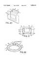
- FIGS. 20 through 22are schematic illustrations showing light emitting panel assemblies in accordance with this invention used to provide lighting for vanity mirrors and the like.
- FIGS. 1 and 2there is schematically shown one form of light emitting panel assembly 1 in accordance with this invention mounted in the hub portion 2 of a steering wheel 3 of a vehicle outwardly of an air bag 4 to provide backlighting for control switches/buttons 5, the horn, logos, or other accent lighting on the steering wheel.
- the light emitting panel assembly 1includes a transparent light emitting panel member 8 having one or more light sources 9 mounted within one or more light transition areas or regions 10 at one or both ends of the panel member mounted within the air bag/steering wheel covering 11 outwardly of the air bag 4.
- a transparent light emitting panel member 8having one or more light sources 9 mounted within one or more light transition areas or regions 10 at one or both ends of the panel member mounted within the air bag/steering wheel covering 11 outwardly of the air bag 4.
- two such light transition areas or regions 10 and light sources 9are shown at one end of one or two panel members 8 for selectively lighting one or two rows of control buttons 5.
- the light that enters the transparent light emitting panel members 8 from the light transition region(s) 10may be emitted along the entire length of the panel members or from one or more light output surface areas along their length as desired to produce a desired light output distribution to fit a particular application.
- the light sources 9may be mechanically held in any suitable manner in slots, cavities or openings machined, molded or otherwise formed in the light transition regions of the panel assemblies. However, the light sources may be embedded, potted or bonded in the light transition regions in order to eliminate any air gaps or air interface surfaces between the light sources and surrounding light transition regions, thereby reducing light loss and increasing the light output emitted by the light emitting panels. Bonding may be accomplished using a suitable embedding, potting or bonding material or by a variety of methods that do not incorporate extra material, for example, thermal bonding, heat staking, ultrasonic or plastic welding or the like. Other methods of bonding include insert molding and casting around the light sources.
- the light sourcesmay be of any suitable type including, for example, any of the types disclosed in U.S. Pat. Nos. 4,897,771 and 5,005,108, assigned to the same assignee as the present application, the entire disclosures of which are incorporated herein by reference.
- the light sourcesmay be non-linear such as an arc lamp, an incandescent bulb which also may be colored, filtered or painted, a lens end bulb, a halogen lamp, a light emitting diode (LED), a chip from an LED, a neon bulb, a fiber optic light pipe transmitting light from a remote light source, a laser or laser diode, or linear such as a line light or fluorescent tube, or any other suitable light source.
- the light sourcesmay be a multiple colored LED, or a combination of multiple colored radiation sources in order to provide a desired colored or white light output distribution.
- a plurality of colored lightssuch as LEDs of different colors (red, blue, green) or a single LED with multiple colored chips may be employed to create white output in other color or shade light output distribution by varying the intensities of each individual colored light.
- a label/overlay with different color light emitting regionscan be used in conjunction with a panel assembly having a plurality of colored light sources for specific indication based on color or the frequency of light emitted by the different light emitting regions.
- a pattern of light extracting deformities or disruptions 12may be provided on one or both sides 13, 14 of the panel members along the entire length thereof or at one or more selected areas of the panel members as desired.
- deformities or disruptionsare used interchangeably herein to mean any change in the shape or geometry of the panel surface and/or coating or surface treatment that causes a portion of the light to be emitted.
- a pattern of light extracting deformitiesmay include a variable pattern which breaks up the light rays such that the internal angle of reflection of a portion of the light rays will be great enough to cause the light rays either to be emitted out of the panel members through the side or sides on which the light extraction deformities are provided or reflected back through the panel members and emitted out the other side.
- Such deformities or disruptionscan be produced in a variety of manners, for example, by providing a painted pattern, an etched pattern, a machined pattern, a printed pattern, a painted pattern, a hot stamped pattern, or a molded pattern or the like at selected light output areas on the surfaces of the panel members.
- An ink or adhesive pattern or printed patternmay be applied for example by pad printing, silk screening, ink jet, photolithography, heat transfer film process or the like.
- the deformitiesmay also be printed on a sheet or film which is used to apply the deformities to the sides of the panel members. This sheet or film may become a permanent part of the light panel assemblies for example by attaching or otherwise positioning the sheet or film against one or both sides of the panel members in order to produce a desired effect.
- the light output of the panel memberscan be controlled.
- the deformities or disruptionsmay be used to control the percent of light emitted from any surface area of the panel members. For example, less and/or smaller size deformities may be placed on panel surface areas where less light output is wanted. Conversely, a greater percentage of and/or larger deformities may be placed on surface areas of the panels where greater light output is desired.
- Varying the percentages and/or size of deformities in different surface areas of the panelsis necessary in order to provide a uniform light output distribution.
- the amount of light traveling through the panelswill ordinarily be greater in areas closer to the light source than in other areas further removed from the light source.
- a pattern of light extracting deformitiesmay be used to adjust for the light variances within the panel members, for example, by providing a denser concentration of light extracting deformities with increased distance from the light source thereby resulting in a more uniform light output distribution from the light emitting panels.
- the deformitiesmay also be used to control the output ray angle distribution of the emitted light to suit a particular application. For example, if the panel assemblies are used to provide a liquid crystal display backlight, the light output will be more efficient if the deformities cause the light rays to be emitted from the panels at predetermined ray angles such that they will pass through the liquid crystal display with low loss.
- the pattern of light extracting deformitiesmay be used to adjust for light output variances attributed to light extractions of the panel members.
- the pattern of light extracting deformitiesmay be printed on the light output surface areas utilizing a wide spectrum of paints, inks, coatings, epoxies, adhesives, or the like, ranging from glossy to opaque or both, and may employ half-tone separation techniques to vary the deformity coverage. If an adhesive is used to provide a pattern of light extracting deformities, the adhesive may also be used to secure a back reflector to the panel member.
- the pattern of light extracting deformitiesmay be multiple layers or vary in index of refraction.
- Print patterns of light extracting deformitiesmay vary in shapes such as dots, squares, diamonds, ellipses, stars, random shapes, and the like, and are desirably 0.006 square inch per deformity/element or less. Also, print patterns that are 60 lines per inch or finer are desirably employed, thus making the deformities or shapes in the print patterns nearly invisible to the human eye in a particular application thereby eliminating the detection of gradient or banding lines that are common to light extracting patterns utilizing larger elements. Additionally, the deformities may vary in shape and/or size along the length and/or width of the panel members. Also, a random placement pattern of the deformities may be utilized throughout the length and/or width of the panel members.
- the deformitiesmay have shapes or a pattern with no specific angles to reduce moire or other interference effects. Examples of methods to create these random patterns are printing a pattern of shapes using stochastic print pattern techniques, frequency modulated half tone patterns, or random dot half tones. Moreover, the deformities may be colored in order to effect color correction in the panel members. The color of the deformities may also vary throughout the panel members, for example to provide different colors for the same or different light output surface areas.
- other light extracting deformitiesincluding prismatic surfaces, depressions or raised surfaces of various shapes using more complex shapes in a mold pattern may be molded, etched, stamped, thermoformed, hot stamped or the like into or on one or more surface areas of the panel members.
- the prismatic surfaces, depressions or raised surfaceswill cause a portion of the light rays contacted thereby to be emitted from the panel members.
- the angles of the prisms, depressions or other surfacesmay be varied to direct the light in different directions to produce a desired light output distribution or effect.
- the reflective or refractive surfacesmay have shapes or a pattern with no specific angles to reduce moire or other interference effects.
- a back reflector or reflective coating (including trans reflectors) 15may be applied to a bottom side of the panel members using a suitable adhesive or other method in order to improve light output efficiency of the panel assemblies by reflecting the light emitted from that side back through the panel members for emission through the opposite side.
- the adhesiveis desirably applied only along the side edges of the panel members so that there is a slight air gap between the back reflector and panel members except where there is adhesive, since the adhesive changes the internal critical angle of the light in a less controllable manner than the air gap between the panel surface and back reflector.
- a pattern of light extracting deformitiesmay be provided on one or both sides of the panel members in order to change the path of the light so that the internal critical angle is exceeded and a portion of the light is emitted from one or both sides of the panel members.
- the back reflectorcan be the same color as the print pattern so that print pattern is not visible through the back reflector.
- a transparent film, sheet or platemay be attached or positioned against the side or sides of the panel members from which light is emitted using a suitable adhesive or other method in order to produce a desired effect.
- the transparent filmmay be used to further improve the uniformity of the light output distribution or change the output ray angle distribution.
- the filmmay be a colored film, a diffuser, or a label or display, a portion of which may be a transparent overlay that may be colored and/or have text or an image thereon.
- the filmmay be a prismatic or lenticular lens or other device that changes the output ray angle distribution.
- the light transition regions or areas 10are shown as an integral extension of one end of the light emitting panel members 8 and as having curved edges 16 to more efficiently reflect and/or refract and focus the light emitted from the light sources that impinges on the curved edges 16 back through the light transition regions at an acceptable angle for entering the light input surface of the light emitting panel members.
- a suitable reflective material or coating 17may be provided on any portions of the edges of the light transition regions of the panel members on which any portion of the light impinges for maximizing the amount of light or otherwise changing the light that is reflected back through the light transition regions and into the light emitting panel members.
- a suitable pattern of light extracting deformities or disruptions 12may be provided on selected areas on one or both sides of the panel members 8 corresponding to the location of the control buttons 5 on the air bag covering 11 above the panel members.
- the pattern of light extracting deformities or depressionsis provided on the bottom side 14 of the panel member 3 (i.e., the side facing away from the control buttons), and a reflective film or coating 15 is provided on that side to reflect the light emitted from that side back through the panel members.
- the light emitting panel members 8are made of a transparent resiliently deformable material such as a thermoplastic elastomer or silicone rubber which allows areas of the panel members in line with the control buttons to be flexed into engagement with a printed circuit 19 located beneath the panel members when the respective control buttons are depressed to complete an associated control circuit. Also if the air bag 4 should ever be deployed or if the driver's head should be forced into engagement with the hub portion 2 of the steering wheel 3 during a traffic accident, the resiliently deformable panel members 8 will absorb shock, thus greatly reducing the possibility of serious injury to the driver because of such contact.
- a transparent resiliently deformable materialsuch as a thermoplastic elastomer or silicone rubber which allows areas of the panel members in line with the control buttons to be flexed into engagement with a printed circuit 19 located beneath the panel members when the respective control buttons are depressed to complete an associated control circuit.
- the resiliently deformable panel members 8will absorb shock, thus greatly reducing the possibility of serious injury to the driver because of such contact.
- the printed circuit 19may be made of a suitable thermoplastic elastomer, silicone rubber or flexible film or laminated circuit or membrane or dome switch to absorb shock, thus further reducing the possibility of serious injury to the driver should the driver's head impact against the hub portion of the steering wheel or should the steering wheel air bag be deployed and force the panel members and circuit outwardly into contact with the driver.
- FIGS. 3 and 4show several automotive exterior lighting applications including one in which a light emitting panel assembly 21 is mounted in a back end or bumper 22 of a vehicle 23 to provide running lights in the back end/bumper, another in which light emitting panel assemblies 24 are mounted in body panels 25 along the rear, front and/or sides of a vehicle to provide running lights or accent lights or to light a logo, step, running board, or other surface area of a vehicle; and still another in which a light emitting panel assembly 26 is mounted in a vehicle trunk lid 27 for providing a running light or illumination for a logo, accent light or license plate mounted on the trunk lid.
- the respective light emitting panel members 28, 29 and 30are shaped to fit the particular application and may be made of a transparent resiliently deformable material such as a thermoplastic elastomer or silicone rubber that will flex upon impact during minor traffic accidents without breakage.
- the number and location of light sources 9 and associated light transition regions 10 for a given light emitting panel membermay vary for a given application depending on the overall size and shape of each panel member and desired amount of light output therefrom.
- the back end/bumper running light application shown in FIGS. 3 and 4may only require one light source 9 and associated light transition region 10 at each end of the panel member 28, whereas the body panel and trunk lid running light applications shown in FIGS. 3 and 4 may require a plurality of closely spaced light sources 9 and associated light transition regions 10 along one or more light input surfaces of the panel members.
- FIG. 3 and 4show several such light sources and associated light transition regions along the back edges of the panel members 29 used to provide running taillights for a vehicle and along a top edge of the panel member 30 used to provide illumination on a trunk lid.
- Mounting all of the light sources for the tail running lights along the back edges of the panel members 29minimizes the risk that the light sources themselves will be damaged in the event the tail running lights are impacted during minor traffic accidents and the like.
- These panel membersmay have a relatively thin, low profile, for example, less than one quarter inch thick, so as not to take up much space.
- these panel members 29may form the exterior surface of the body panel 25 as shown at the left hand side of FIG. 4 or a lens or film 34 may cover the panel members as shown at the right hand side of FIG. 4.
- FIG. 3shows the light source 9 at the left end of panel member 28 mechanically held in place by a holder 63 received in a slot in an edge of the panel member. Also a fiber optic light pipe 64 is shown at the right end of the panel member 28 of FIG. 3 for transmitting light to the panel member from a remote light source 65 located for example in the trunk or other remote location in the vehicle.
- An additional array of light sources 31such as LEDs or incandescent or halogen lamps (with or without reflectors) may also be strategically mounted inwardly (i.e., behind) the inner surface of the light emitting panel members 29 and/or 30 to cause a more intense light to shine through the panel members and a trans reflector 32 if provided on the panel members or through one or more clear areas or holes 33 through the panel members where no print pattern, back reflector or trans reflector is provided on the panel members as also schematically shown in FIGS. 3 and 4 for specific applications, for example, to provide brake or turn signal lights, turning or backup illumination, etc.
- the panel membercould be made of a rigid transparent material such as polycarbonate or acrylic plastic instead of a resiliently deformable material if desired.
- FIGS. 5 and 6schematically show another form of light emitting panel assembly 35 in accordance with this invention including a resiliently deformable transparent light emitting panel member 36 mounted behind an LCD 37 and/or multiple control buttons 38 of a radio or other device for illumination of the LCD and control buttons either by causing light to be uniformly emitted from the entire surface of the panel member or from specific surface areas of the panel member in the regions of the LCD and control buttons as desired. Any number of light sources 9 and associated light transition regions 10 may be provided for the panel member 36 as desired.
- the panel member 36is desirably made of a resiliently deformable elastomeric material so that when the control buttons 38, which may either be membrane switches or elastomeric key pads that are molded or embossed, are depressed into engagement with the panel member, the engaged areas of the panel member will flex into engagement with associated dome switches 39' or other circuitry on a printed circuit 39 beneath the panel member to effect the selected switching function.
- the control buttons 38which may either be membrane switches or elastomeric key pads that are molded or embossed
- a light emitting panel member 40 in accordance with this inventionmay be made of a relatively rigid transparent material such as polycarbonate or acrylic plastic, with through holes 41 in the panel member in alignment with membrane switches or elastomeric key pads 42 or other such control buttons (see FIG. 7) to permit contact portions 43 on the control buttons to engage appropriate circuitry on a printed circuit 44 inwardly of the panel member when the control buttons are depressed.
- the control buttons 42may be used to activate dome switches (one such dome switch 57 being shown toward the right end of FIG. 7), in which event the contact portions 43 may be eliminated.
- the holes 41may be of various shapes or have angled or textured walls 45 (the wall 45 of the right most hole 41 of FIG. 7 being shown angled) to cause a portion of the light to be emitted toward the control buttons.
- light entering the panel member from the light source 9 and associated light transition region 10will be emitted from the walls 45 of the holes 41 in the panel member to backlight the switches/pads.
- surface irregularities 46such as print patterns may be provided around the holes 41 in the panel member as schematically shown in FIG. 7A to cause light to be emitted around the control buttons to flood the area around the control buttons with light.
- Surface irregularities 46such as print patterns or molded in shapes may also be provided on other surface areas of the panel member 36, for example, behind the LCD 37 and control buttons 38 for backlighting purposes, etc.
- FIG. 8schematically shows a flush mount application for a light emitting panel assembly 47 in accordance with this invention in which a resiliently deformable elastomeric transparent light emitting panel member 48 is mounted behind a contoured surface such as the dash 49 of a vehicle on which control switches 50 or a logo or the like are mounted.
- the switches 50include transparent or translucent key pads 51 or 51' that may be molded into the contoured surface as shown in the center portion of FIG. 8 or molded onto the panel member 48 and extend through openings 49' in the contoured surface as shown to the left and right of center in FIG. 8.
- the key pads 51, 51'are desirably made of an elastomeric or other flexible material, which together with the panel member 48, provide a soft assembly that absorbs impact to minimize injury to a person thrown against the dash during a traffic accident or the like. Also making the panel member 48 out of a resiliently deformable elastomeric material permits selected areas of the panel member to be pressed into contact/engagement with a printed circuit 52 therebeneath when the key pads are depressed.
- the printed circuit and panel membermay include appropriate circuitry 53, 54 such as conducting ink printed on adjacent surfaces to complete an appropriate circuit when brought into contact with each other.
- dome switches 57may be provided for engagement by the key pads (one such dome switch being shown toward the right end of FIG.
- the printed circuit 52may be made of a suitable resiliently deformable elastomeric material or flexible film for contouring and to help in providing a soft assembly to absorb impact during a traffic accident or the like.
- FIGS. 9 and 10schematically illustrate another form of light emitting panel assembly 56 in accordance with this invention for use with dome switches 57 for switch array lighting, keyless entry, radio and/or tape/CD controls or other such applications.
- a relatively rigid transparent light emitting panel member 58extends through transverse openings or slots 59 (see FIG. 10) in an array of push buttons 60 in line with the dome switches 57.
- the ends or other sections of the panel memberare supported by a rigid tray 61 containing or in close proximity to a printed circuit 62 on which the dome switches may be mounted.
- the height of the slots 59 through the push buttons 60is greater than the thickness of the panel member 58 whereby the push buttons will float on the panel member, thus allowing the push buttons to be pressed into contact with the respective dome switches on the printed circuit to activate appropriate circuitry.
- FIGS. 9 and 10show a single panel member 58 with associated light sources 9 and light transition regions 10 at one or both ends thereof for illuminating single indicator buttons 60
- FIG. 11shows two light emitting panel members 66, 67 with separate light sources 9 and associated light transition regions 10 for illuminating dual indicator buttons 68 for illuminating radio controls and/or tape/CD controls or the like.
- Surface irregularitiessuch as print patterns or molded in shapes may be provided on selected surface areas of the panel members within and/or around the push buttons to cause light to illuminate the buttons.
- FIGS. 12 through 15schematically illustrate another form of light emitting panel assembly 70 in accordance with this invention including two or more stacked relatively rigid transparent light emitting panel members 71, 72 in a multi-layer instrument panel 73.
- the outer (i.e. upper) panel member 71shown in plan view in FIG. 14, provides a structural support for a graphic overlay 74, shown in plan view in FIG. 13.
- Pointers 75are supported outwardly of the graphic overlay 74 by shafts 76 (see FIG. 12) which extend through the panel members and are rotatably driven by motor controllers 77 inwardly (i.e. below) of the panel members.
- the pointersmay be illuminated as by providing prismatic surfaces 78 and/or surface irregularities around openings 79 in the outer panel member 71 through which the shafts 76 extend for reflecting/refracting light within the outer panel member into the pointers 75.
- the pointers 75may also be made of a light transmitting material, with prismatic surfaces 80 at one end of the pointers to cause light received from the outer panel member to be reflected/refracted back through the pointers and emitted through light emitting surface areas on the pointers.
- the inner (i.e. lower) panel member 72shown in plan view in FIG. 15, includes different shaped light emitting surface areas 83, 84 and 85 for emitting light entering the panel member from one or more light sources for backlighting the graphic overlay 74 mounted on the outer surface of the outer panel member 71.
- each panel member 71, 72may be provided for each panel member 71, 72 as desired.
- common light sources 86 for both panel members 71, 72extend into aligned openings 87, 88 in the panel members.
- separate indicator lights 89may be mounted at selected positions on a printed circuit 90 inwardly of both panel members 71, 72 for shining light through both panel members to different indicators 91 on the graphic overlay 74 as schematically shown in FIGS. 12 and 13.
- Suitable shields/reflectors 92may be provided around/between the indicator lights 89 (see FIG. 12) to shield the light and direct it to the appropriate indicators.
- FIG. 16shows another form of light emitting panel assembly 93 in accordance with this invention including a rigid transparent light emitting panel member 94 which may act as a structural support for a graphic overlay/decal 95 used, for example, to designate the various gear shift lever positions for the engine of a vehicle.
- One or more light sources 9may be inserted/embedded within light transition regions 10 on the panel member to provide backlighting at selected surface areas 96 along the length of the panel member corresponding for example to the different gear shift selector positions (viz. P R N D L) or to provide accent lighting or backlighting for a logo.
- 16is generally L shaped, with an angled reflective surface 97 interconnecting the legs 98, 99 of the panel member for reflecting a portion of the light from the light source 9 on one of the legs 98 of the panel member around a corner 100 for providing backlighting at one or more selected areas 101 on the other leg 99 of the panel member.
- the panel member 102can be curved in one or more planes as schematically shown in FIG. 17.
- two such panel members 102, 102'may be provided as shown in FIG. 17 for designating the different gear shift lever positions of a four wheel drive vehicle.
- the two panel membersare joined together and a common light source 9 is used to supply light to both panel members, with reflective surfaces 103, 103' at the corners 104, 104' for reflecting/refracting a portion of the light around the corners.
- the panel member 105may be substantially straight as schematically shown in FIG. 18.
- a plurality of indicator lights 106may also be located along an edge of the panel members in line with the light emitting surface areas 96 corresponding to the respective gear shift lever positions as schematically shown in FIG. 16 for providing increased light output at these positions. Also, additional light sources 106' may be placed behind the panel members for shining light through the light emitting surface areas or other surface areas of the panel member as shown in phantom lines in FIG. 16.
- a filter 107may be interposed between the panel members and associated graphic overlay 95 for movement with a gear selector shift lever 108 into overlying relation with any one of the light emitting surface areas 96 on the panel members corresponding to the selected gear shift position as schematically shown in FIG. 18 to provide a different color or shade of light output at the selected gear shift position.
- the filter 107may be a red filter that changes the color of the light output at the selected gear shift position from white to red.
- tabs 109which may be used for example to heat stake the panel member to a back reflector tray 110 for the panel member as schematically shown in FIG. 19.
- posts 111may be provided on the panel members for heat staking the overlay/label 95 to the panel members and/or heat staking the panel members to an interior body panel of the vehicle.
- FIGS. 20 through 22show other forms of light emitting panel assemblies 115, 116 and 117 in accordance with this invention including respective light emitting panel members 118, 119 and 120 mounted on the flap 121 of a vanity mirror 122 (see FIG. 20), extending around three sides of a generally rectangular vanity mirror 123 (see FIG. 21), and extending substantially completely around an elliptical vanity mirror 124 (see FIG. 21).
- Such panel members 118, 119 and 120have a relatively thin, low profile, for example less than one quarter inch thick, with one or more light sources 9 and light transition regions 10 at one or both ends of the panel members to produce a uniform diffuse, shadowless light around the vanity mirror.
- FIG. 20shows other forms of light emitting panel assemblies 115, 116 and 117 in accordance with this invention including respective light emitting panel members 118, 119 and 120 mounted on the flap 121 of a vanity mirror 122 (see FIG. 20), extending around three sides of a generally rectangular vanity mirror 123 (see FIG. 21), and extending
- the panel member 118is shown mounted on the vanity mirror flap 121
- the panel memberis generally straight and extends substantially the entire length of the mirror in generally parallel relation thereto, with light sources 9 and associated light transition region 10 at one end of the panel member.
- the panel member 116is generally U shaped and is configured to extend substantially the full length of three sides of the mirror in generally parallel relation and in close proximity thereto
- the panel member 120is generally elliptical in shape.
- the panel members 119 and 120have one or more light sources 9 and associated light transition regions 10 at both ends of the panel members.
- reflective surfaces 125are provided at the corners/curves 126, 127 of the panel members 119, 120 for reflecting a portion of the light around the corners/curves.
Landscapes
- Engineering & Computer Science (AREA)
- Mechanical Engineering (AREA)
- Physics & Mathematics (AREA)
- General Physics & Mathematics (AREA)
- Theoretical Computer Science (AREA)
- Illuminated Signs And Luminous Advertising (AREA)
- Arrangements Of Lighting Devices For Vehicle Interiors, Mounting And Supporting Thereof, Circuits Therefore (AREA)
- Securing Globes, Refractors, Reflectors Or The Like (AREA)
- Non-Portable Lighting Devices Or Systems Thereof (AREA)
- Led Device Packages (AREA)
- Instrument Panels (AREA)
- Planar Illumination Modules (AREA)
- Lighting Device Outwards From Vehicle And Optical Signal (AREA)
Abstract
Description
Claims (16)
Priority Applications (15)
| Application Number | Priority Date | Filing Date | Title |
|---|---|---|---|
| US08/585,062US5895115A (en) | 1996-01-16 | 1996-01-16 | Light emitting panel assemblies for use in automotive applications and the like |
| TW085105445ATW350822B (en) | 1996-01-16 | 1996-05-08 | Light emitting panel assemblies for use in automotive applications and the like |
| EP97300059AEP0801373B1 (en) | 1996-01-16 | 1997-01-07 | Light emitting panel assemblies for use in automotive applications |
| EP08005524AEP1975958A3 (en) | 1996-01-16 | 1997-01-07 | Light emitting panel assemblies for use in automotive applications and the like |
| DE69730642TDE69730642T2 (en) | 1996-01-16 | 1997-01-07 | Luminous panels for use in automotive applications |
| EP04007904AEP1443482B1 (en) | 1996-01-16 | 1997-01-07 | Light emitting panel assemblies for use in automotive applications and the like |
| DE69739290TDE69739290D1 (en) | 1996-01-16 | 1997-01-07 | Luminous panels for use in automotive applications and the like |
| JP00586297AJP4326602B2 (en) | 1996-01-16 | 1997-01-16 | Luminescent panel assembly |
| US09/167,949US6158867A (en) | 1996-01-16 | 1998-10-07 | Light emitting panel assemblies for use in automotive applications and the like |
| US09/703,088US6367940B1 (en) | 1996-01-16 | 2000-10-31 | Light emitting panel assemblies for use in automotive applications and the like |
| US10/005,090US6508563B2 (en) | 1996-01-16 | 2001-12-05 | Light emitting panel assemblies for use in automotive applications and the like |
| US10/298,367US6886956B2 (en) | 1996-01-16 | 2002-11-18 | Light emitting panel assemblies for use in automotive applications and the like |
| US10/712,622US6796668B2 (en) | 1996-01-16 | 2003-11-13 | Light emitting panel assemblies for use in automotive applications and the like |
| JP2007277026AJP2008065346A (en) | 1996-01-16 | 2007-10-24 | Light emitting panel assembly |
| JP2009101478AJP2009227275A (en) | 1996-01-16 | 2009-04-17 | Light emitting panel assembly |
Applications Claiming Priority (1)
| Application Number | Priority Date | Filing Date | Title |
|---|---|---|---|
| US08/585,062US5895115A (en) | 1996-01-16 | 1996-01-16 | Light emitting panel assemblies for use in automotive applications and the like |
Related Child Applications (1)
| Application Number | Title | Priority Date | Filing Date |
|---|---|---|---|
| US09/167,949DivisionUS6158867A (en) | 1996-01-16 | 1998-10-07 | Light emitting panel assemblies for use in automotive applications and the like |
Publications (1)
| Publication Number | Publication Date |
|---|---|
| US5895115Atrue US5895115A (en) | 1999-04-20 |
Family
ID=24339897
Family Applications (6)
| Application Number | Title | Priority Date | Filing Date |
|---|---|---|---|
| US08/585,062Expired - LifetimeUS5895115A (en) | 1996-01-16 | 1996-01-16 | Light emitting panel assemblies for use in automotive applications and the like |
| US09/167,949Expired - LifetimeUS6158867A (en) | 1996-01-16 | 1998-10-07 | Light emitting panel assemblies for use in automotive applications and the like |
| US09/703,088Expired - LifetimeUS6367940B1 (en) | 1996-01-16 | 2000-10-31 | Light emitting panel assemblies for use in automotive applications and the like |
| US10/005,090Expired - LifetimeUS6508563B2 (en) | 1996-01-16 | 2001-12-05 | Light emitting panel assemblies for use in automotive applications and the like |
| US10/298,367Expired - Fee RelatedUS6886956B2 (en) | 1996-01-16 | 2002-11-18 | Light emitting panel assemblies for use in automotive applications and the like |
| US10/712,622Expired - Fee RelatedUS6796668B2 (en) | 1996-01-16 | 2003-11-13 | Light emitting panel assemblies for use in automotive applications and the like |
Family Applications After (5)
| Application Number | Title | Priority Date | Filing Date |
|---|---|---|---|
| US09/167,949Expired - LifetimeUS6158867A (en) | 1996-01-16 | 1998-10-07 | Light emitting panel assemblies for use in automotive applications and the like |
| US09/703,088Expired - LifetimeUS6367940B1 (en) | 1996-01-16 | 2000-10-31 | Light emitting panel assemblies for use in automotive applications and the like |
| US10/005,090Expired - LifetimeUS6508563B2 (en) | 1996-01-16 | 2001-12-05 | Light emitting panel assemblies for use in automotive applications and the like |
| US10/298,367Expired - Fee RelatedUS6886956B2 (en) | 1996-01-16 | 2002-11-18 | Light emitting panel assemblies for use in automotive applications and the like |
| US10/712,622Expired - Fee RelatedUS6796668B2 (en) | 1996-01-16 | 2003-11-13 | Light emitting panel assemblies for use in automotive applications and the like |
Country Status (5)
| Country | Link |
|---|---|
| US (6) | US5895115A (en) |
| EP (3) | EP1443482B1 (en) |
| JP (3) | JP4326602B2 (en) |
| DE (2) | DE69739290D1 (en) |
| TW (1) | TW350822B (en) |
Cited By (114)
| Publication number | Priority date | Publication date | Assignee | Title |
|---|---|---|---|---|
| WO2000012226A1 (en)* | 1998-08-28 | 2000-03-09 | Fed Corporation | Full color organic light emitting diode display and method for making the same using inkjet fabrication |
| US6050702A (en)* | 1998-04-21 | 2000-04-18 | Rahmonic Resources Pte. Ltd. | Apparatus and method to provide custom lighting |
| US6132072A (en)* | 1996-06-13 | 2000-10-17 | Gentex Corporation | Led assembly |
| US6218790B1 (en)* | 1998-03-11 | 2001-04-17 | Mannesmann Vdo Ag | Connection assembly with selective establishment of intensity of light-emitting diode |
| US6296380B1 (en)* | 1999-03-18 | 2001-10-02 | Aboud Dawli | Lighted steering wheel |
| WO2001098708A1 (en)* | 2000-06-19 | 2001-12-27 | Light Sciences Corporation | Flexible substrate mounted solid-state light sources for exterior vehicular lighting |
| US6461028B1 (en)* | 2001-06-15 | 2002-10-08 | Chin-Jeng Huang | Vehicle side bumper and signal light assembly |
| US6509832B1 (en) | 1998-09-15 | 2003-01-21 | Gentex Corporation | Systems and components for enhancing rear vision from a vehicle |
| US6508563B2 (en)* | 1996-01-16 | 2003-01-21 | Solid State Opto Limited | Light emitting panel assemblies for use in automotive applications and the like |
| US20030016533A1 (en)* | 2000-03-23 | 2003-01-23 | Forsythe John D. | Security flashlight and method |
| US20030043590A1 (en)* | 2001-08-31 | 2003-03-06 | Walser Jeremy A. | Vehicle lamp assembly with heat sink |
| US20030103141A1 (en)* | 1997-12-31 | 2003-06-05 | Bechtel Jon H. | Vehicle vision system |
| US6588924B1 (en)* | 1999-03-08 | 2003-07-08 | Mannesmann Vdo Ag | Display unit with a front instrument panel and process for producing such a front instrument panel |
| US20040066659A1 (en)* | 2002-10-04 | 2004-04-08 | Mezei George A. | Transparent light emitting members and method of manufacture |
| US20040108970A1 (en)* | 2002-12-04 | 2004-06-10 | Nealon Brian Clark | Vehical graphical message display system |
| US6773644B1 (en) | 2001-08-29 | 2004-08-10 | Nokia Corporation | Method of making illuminated covers |
| US6816083B2 (en) | 2002-02-04 | 2004-11-09 | Nokia Corporation | Electronic device with cover including a radio frequency indentification module |
| US20040239243A1 (en)* | 1996-06-13 | 2004-12-02 | Roberts John K. | Light emitting assembly |
| US20040264163A1 (en)* | 2003-06-26 | 2004-12-30 | Te-Hsiang Fang | Light guide |
| US6864787B1 (en)* | 2001-12-05 | 2005-03-08 | Sherri Coseo Veach | Front safety brake lights |
| US20050063194A1 (en)* | 1997-08-26 | 2005-03-24 | Color Kinetics, Incorporated | Vehicle lighting methods and apparatus |
| US20050242607A1 (en)* | 2002-08-31 | 2005-11-03 | Johnson Controls Technology Company | Lining element for the interior of a vehicle |
| US20060055665A1 (en)* | 2004-09-14 | 2006-03-16 | Xerox Corporation. | User interface having button delineating control panel |
| US20060103544A1 (en)* | 2004-11-03 | 2006-05-18 | Bernd Merz | Vehicle light |
| US20060187531A1 (en)* | 2005-02-23 | 2006-08-24 | Pixtronix, Incorporated | Methods and apparatus for bi-stable actuation of displays |
| US20060187528A1 (en)* | 2005-02-23 | 2006-08-24 | Pixtronix, Incorporated | Methods and apparatus for spatial light modulation |
| US20060250676A1 (en)* | 2005-02-23 | 2006-11-09 | Pixtronix, Incorporated | Light concentrating reflective display methods and apparatus |
| US20060290647A1 (en)* | 2005-06-28 | 2006-12-28 | Kilolambda Technologies Ltd. | Optical waveguided dashboard display |
| US20070041110A1 (en)* | 2005-08-22 | 2007-02-22 | Gentex Corporation | Vehicular rearview components and assemblies |
| US7182492B1 (en)* | 2003-12-22 | 2007-02-27 | Robert Louis Walter | License plate system having enhanced illumination |
| US20070208226A1 (en)* | 2006-01-18 | 2007-09-06 | Spotlight Surgical, Inc. | Retractor illumination system |
| US20070211459A1 (en)* | 2006-02-22 | 2007-09-13 | Yazaki North America, Inc. | Display with housing having cavity for secondary light source |
| US7271945B2 (en) | 2005-02-23 | 2007-09-18 | Pixtronix, Inc. | Methods and apparatus for actuating displays |
| US20070248307A1 (en)* | 2002-10-04 | 2007-10-25 | Page David J | Transparent light emitting members and method of manufacture |
| US7304785B2 (en) | 2005-02-23 | 2007-12-04 | Pixtronix, Inc. | Display methods and apparatus |
| US20070293729A1 (en)* | 2006-05-26 | 2007-12-20 | Spotlight Surgical, Inc. | Blade insert illuminator |
| US20080025039A1 (en)* | 2006-07-20 | 2008-01-31 | Int America, Llc | Fiber optic auxilliary lighting system |
| US7336980B1 (en) | 2001-05-29 | 2008-02-26 | Nokia Corporation | Outer decorative cover for attachment to a wireless communication device including a printed circuit board and an associated light source mounted in an interior of the wireless device |
| US20080062711A1 (en)* | 2006-08-21 | 2008-03-13 | Veenstra Thomas J | Electrical device having boardless electrical component mounting arrangement |
| US20080129083A1 (en)* | 2004-03-15 | 2008-06-05 | Daimlerchrysler Ag | Vehicle Film Component, and Method for the Production Thereof |
| US7405852B2 (en) | 2005-02-23 | 2008-07-29 | Pixtronix, Inc. | Display apparatus and methods for manufacture thereof |
| US20080201665A1 (en)* | 2007-02-15 | 2008-08-21 | Teac Corporation | Electronic equipment having plural function keys |
| US20080253140A1 (en)* | 2007-03-19 | 2008-10-16 | Fleischmann Eric L | Light for vehicles |
| US7502159B2 (en) | 2005-02-23 | 2009-03-10 | Pixtronix, Inc. | Methods and apparatus for actuating displays |
| US20090112068A1 (en)* | 2007-10-24 | 2009-04-30 | Spotlight Surgical, Inc. | Blade Insert Illuminator |
| US20090213606A1 (en)* | 2005-08-31 | 2009-08-27 | Osram Sylvania, Inc. | LED headlamp system |
| US20090310380A1 (en)* | 2008-06-16 | 2009-12-17 | Gurpreet Aulakh | Concealed illuminated center high mount stop lamp (chmsl) |
| US20100025214A1 (en)* | 2008-07-31 | 2010-02-04 | Electrolux Home Products | Unitized Appliance Control Panel Assembly and Components of the Assembly |
| US7675665B2 (en) | 2005-02-23 | 2010-03-09 | Pixtronix, Incorporated | Methods and apparatus for actuating displays |
| US20100061076A1 (en)* | 2008-09-10 | 2010-03-11 | Man-D-Tec | Elevator Interior Illumination Method and Assembly |
| US7742016B2 (en) | 2005-02-23 | 2010-06-22 | Pixtronix, Incorporated | Display methods and apparatus |
| US7746529B2 (en) | 2005-02-23 | 2010-06-29 | Pixtronix, Inc. | MEMS display apparatus |
| US7755582B2 (en) | 2005-02-23 | 2010-07-13 | Pixtronix, Incorporated | Display methods and apparatus |
| US20100186214A1 (en)* | 2007-03-19 | 2010-07-29 | Judge Michael K | Light for vehicles |
| US20100218641A1 (en)* | 2007-09-06 | 2010-09-02 | Delf Neumann | Steering wheel assembly for a motor vehicle |
| US7815339B2 (en) | 2008-01-09 | 2010-10-19 | Innotec Corporation | Light module |
| US7839356B2 (en) | 2005-02-23 | 2010-11-23 | Pixtronix, Incorporated | Display methods and apparatus |
| US7852546B2 (en) | 2007-10-19 | 2010-12-14 | Pixtronix, Inc. | Spacers for maintaining display apparatus alignment |
| US7876489B2 (en) | 2006-06-05 | 2011-01-25 | Pixtronix, Inc. | Display apparatus with optical cavities |
| US20110157679A1 (en)* | 2008-08-04 | 2011-06-30 | Pixtronix, Inc. | Methods for manufacturing cold seal fluid-filled display apparatus |
| US8159428B2 (en) | 2005-02-23 | 2012-04-17 | Pixtronix, Inc. | Display methods and apparatus |
| US8230575B2 (en) | 2007-12-12 | 2012-07-31 | Innotec Corporation | Overmolded circuit board and method |
| US8248560B2 (en) | 2008-04-18 | 2012-08-21 | Pixtronix, Inc. | Light guides and backlight systems incorporating prismatic structures and light redirectors |
| US8262274B2 (en) | 2006-10-20 | 2012-09-11 | Pitronix, Inc. | Light guides and backlight systems incorporating light redirectors at varying densities |
| US8310442B2 (en) | 2005-02-23 | 2012-11-13 | Pixtronix, Inc. | Circuits for controlling display apparatus |
| US8482496B2 (en) | 2006-01-06 | 2013-07-09 | Pixtronix, Inc. | Circuits for controlling MEMS display apparatus on a transparent substrate |
| US8519945B2 (en) | 2006-01-06 | 2013-08-27 | Pixtronix, Inc. | Circuits for controlling display apparatus |
| US8526096B2 (en) | 2006-02-23 | 2013-09-03 | Pixtronix, Inc. | Mechanical light modulators with stressed beams |
| US8599463B2 (en) | 2008-10-27 | 2013-12-03 | Pixtronix, Inc. | MEMS anchors |
| US20140060387A1 (en)* | 2010-12-06 | 2014-03-06 | Construction Research & Technology Gmbh | Method For Preparing Admixture Blends For Construction Material On Site And A Micro-Plant For Implementing The Method |
| US20140240589A1 (en)* | 2011-10-27 | 2014-08-28 | Robert Bosch Gmbh | Front cover for a housing enclosing a camera |
| US8915630B2 (en)* | 1995-04-21 | 2014-12-23 | Magna Mirrors Of America, Inc. | Vehicle exterior mirror system |
| US8925959B2 (en) | 2013-01-29 | 2015-01-06 | Tasus Canada Corporation | Illuminated emblem assembly for connection to an airbag cover |
| US20150069740A1 (en)* | 2012-03-27 | 2015-03-12 | Takata Corporation | Airbag unit, fastening structure, and fastening member |
| US9004713B2 (en) | 2008-09-10 | 2015-04-14 | Man-D-Tec, Inc. | Illumination assembly |
| US9022631B2 (en) | 2012-06-13 | 2015-05-05 | Innotec Corp. | Flexible light pipe |
| US9067556B2 (en) | 2013-01-29 | 2015-06-30 | Tasus Canada Corporation | Illuminated emblem assembly for connection to an airbag cover |
| US9082353B2 (en) | 2010-01-05 | 2015-07-14 | Pixtronix, Inc. | Circuits for controlling display apparatus |
| US9087486B2 (en) | 2005-02-23 | 2015-07-21 | Pixtronix, Inc. | Circuits for controlling display apparatus |
| US9134552B2 (en) | 2013-03-13 | 2015-09-15 | Pixtronix, Inc. | Display apparatus with narrow gap electrostatic actuators |
| US9135868B2 (en) | 2005-02-23 | 2015-09-15 | Pixtronix, Inc. | Direct-view MEMS display devices and methods for generating images thereon |
| US9176318B2 (en) | 2007-05-18 | 2015-11-03 | Pixtronix, Inc. | Methods for manufacturing fluid-filled MEMS displays |
| US9200784B2 (en) | 2013-03-15 | 2015-12-01 | Man-D-Tec, Inc. | Downward illumination assembly |
| US9229222B2 (en) | 2005-02-23 | 2016-01-05 | Pixtronix, Inc. | Alignment methods in fluid-filled MEMS displays |
| US9261694B2 (en) | 2005-02-23 | 2016-02-16 | Pixtronix, Inc. | Display apparatus and methods for manufacture thereof |
| US9453639B2 (en) | 2013-09-24 | 2016-09-27 | Mandy Holdings Lllp | Rectilinear light source for elevator interior |
| US9500853B2 (en) | 2005-02-23 | 2016-11-22 | Snaptrack, Inc. | MEMS-based display apparatus |
| US9556648B2 (en) | 2013-03-12 | 2017-01-31 | Ford Global Technologies, Llc | Retractable striker cover assembly for vehicle |
| US9586526B2 (en) | 1995-04-21 | 2017-03-07 | Magna Mirrors Of America, Inc. | Vehicle exterior mirror system |
| US20170144593A1 (en)* | 2015-11-25 | 2017-05-25 | Continental Automotive Systems, Inc. | Light guide assembly |
| US9696022B2 (en) | 2013-03-14 | 2017-07-04 | Mandy Holdings Lllp | Downward illumination assembly |
| US9815406B2 (en) | 2012-10-23 | 2017-11-14 | Tk Holdings, Inc. | Steering wheel light bar |
| US9821703B2 (en) | 2012-10-23 | 2017-11-21 | Tk Holdings, Inc. | Steering wheel light bar |
| US9873446B2 (en) | 2014-07-23 | 2018-01-23 | Tk Holdings, Inc. | Steering grip light bar systems |
| US9933144B2 (en) | 2013-09-20 | 2018-04-03 | Man-D-Tec, Inc. | Light fixture mounting assembly |
| US10036843B2 (en) | 2015-04-24 | 2018-07-31 | Joyson Safety Systems Acquisition Llc | Steering wheel light bar |
| US10046786B2 (en) | 2014-12-30 | 2018-08-14 | Joyson Safety Systems Acquisition Llc | Occupant monitoring systems and methods |
| US10144347B1 (en) | 2017-10-16 | 2018-12-04 | Jvis-Usa, Llc | Illuminator assembly for a safety belt buckle |
| US20180370422A1 (en)* | 2017-06-27 | 2018-12-27 | Ford Global Technologies, Llc | Exterior Compartment Light |
| US10259387B1 (en) | 2017-10-16 | 2019-04-16 | Jvis-Usa, Llc | Illuminated vehicle interior assembly such as a safety belt buckle assembly |
| US10279736B2 (en) | 2017-06-29 | 2019-05-07 | Jvis-Usa, Llc | Vehicle interior trim assembly configured to form a light pattern having an emblem shape at the front of a trim part such as an air bag cover |
| US10507764B2 (en) | 2017-06-29 | 2019-12-17 | Jvis-Usa, Llc | Vehicle interior trim assembly configured to form a light pattern having an emblem shape at the front of a trim part such as an air bag cover |
| US10532659B2 (en) | 2014-12-30 | 2020-01-14 | Joyson Safety Systems Acquisition Llc | Occupant monitoring systems and methods |
| US10614328B2 (en) | 2014-12-30 | 2020-04-07 | Joyson Safety Acquisition LLC | Occupant monitoring systems and methods |
| US10672327B1 (en) | 2019-01-02 | 2020-06-02 | Jvis-Usa, Llc | Low-profile display assembly for a vehicle and configured to display computer-generated imagery at the front of the assembly |
| US10696217B2 (en) | 2017-01-04 | 2020-06-30 | Joyson Safety Systems Acquisition | Vehicle illumination systems and methods |
| CN111668202A (en)* | 2019-03-08 | 2020-09-15 | 日亚化学工业株式会社 | light source device |
| US10906476B2 (en) | 2014-04-29 | 2021-02-02 | Global Ip Holdings, Llc | Vehicle trim part having a layered, decorative finish and configured to form a light pattern at the front of the part |
| US11382711B2 (en) | 2008-08-13 | 2022-07-12 | Invuity, Inc. | Cyclo olefin polymer and copolymer medical devices |
| US11535150B2 (en) | 2021-01-15 | 2022-12-27 | Honda Motor Co., Ltd. | Lighting system having light assembly removably coupled to powering surface assembly |
| US11766972B2 (en) | 2019-01-02 | 2023-09-26 | Jvis-Usa, Llc | Low-profile, backlit, panel assembly for displaying images and/or data within a passenger compartment of a vehicle |
| US11772700B2 (en) | 2018-03-08 | 2023-10-03 | Joyson Safety Systems Acquisition Llc | Vehicle illumination systems and methods |
| US11898720B2 (en) | 2020-01-15 | 2024-02-13 | Man-D-Tec, Inc. | Downlight fixture housing fabrication |
| US12434651B1 (en)* | 2024-05-24 | 2025-10-07 | Hyundai Mobis Co., Ltd. | Airbag cover assembly including a lighting module |
Families Citing this family (151)
| Publication number | Priority date | Publication date | Assignee | Title |
|---|---|---|---|---|
| AU3209600A (en)* | 1999-01-14 | 2000-08-01 | Federal Mogul Corporation | Waveguide assembly for laterally-directed illumination in a vehicle lighting system |
| DE19902244A1 (en)* | 1999-01-21 | 2000-08-03 | Daimler Chrysler Ag | Headlining with a transparent roof element |
| US6499852B1 (en)* | 1999-09-07 | 2002-12-31 | Toyoda Gosei Co., Ltd. | Vehicle display lighting device |
| GB2356965B (en)* | 1999-12-03 | 2003-10-08 | Ncr Int Inc | Self-service terminal |
| DE19958725A1 (en)* | 1999-12-06 | 2001-06-07 | Mannesmann Vdo Ag | Control unit with illuminated controls |
| US6454422B1 (en)* | 2000-10-26 | 2002-09-24 | Trw Inc. | Backlit indicia on a painted surface |
| US6652128B2 (en)* | 2001-01-31 | 2003-11-25 | Textron Automotive Company, Inc. | Backlighting method for an automotive trim panel |
| CA2442032A1 (en)* | 2001-03-28 | 2002-10-10 | Barbara Sexton | Computer |
| US6854870B2 (en)* | 2001-06-30 | 2005-02-15 | Donnelly Corporation | Vehicle handle assembly |
| US6519140B1 (en)* | 2001-09-13 | 2003-02-11 | Sun Microsystems, Inc. | Hinged bezel for a computer system |
| JP4067802B2 (en)* | 2001-09-18 | 2008-03-26 | 松下電器産業株式会社 | Lighting device |
| US6874926B2 (en)* | 2001-11-26 | 2005-04-05 | Nokia Corporation | Illumination system for an electronic device |
| US6864496B2 (en)* | 2002-05-01 | 2005-03-08 | Chris Levine | Lighting effect generator |
| US6905237B2 (en)* | 2002-08-26 | 2005-06-14 | William Alan Jacobs | Fiber optic lighting radial arrangement and method for forming the same |
| US6836611B2 (en)* | 2002-10-03 | 2004-12-28 | J. W. Speaker Corporation | Light guide and lateral illuminator |
| US7406245B2 (en) | 2004-07-27 | 2008-07-29 | Lumitex, Inc. | Flat optical fiber light emitters |
| TW547774U (en)* | 2002-10-23 | 2003-08-11 | Benq Corp | Light emitting diode |
| US20040085746A1 (en)* | 2002-11-05 | 2004-05-06 | Chen Shih Ling | Instrument panel with colorful illumination |
| US7671859B2 (en)* | 2002-11-06 | 2010-03-02 | Continental Automotive Systems Us, Inc. | Thin instrument cluster with anti-reflective coating |
| US6975369B1 (en)* | 2002-12-12 | 2005-12-13 | Gelcore, Llc | Liquid crystal display with color backlighting employing light emitting diodes |
| US6974220B2 (en)* | 2002-12-12 | 2005-12-13 | Siemens Vdo Automotive Corporation | Bright pointer for instrument cluster |
| US6737592B1 (en)* | 2003-03-14 | 2004-05-18 | Motorola, Inc. | Switch assembly for operating a device in different operational modes |
| US20040200121A1 (en)* | 2003-03-20 | 2004-10-14 | Lord Octave E. | Lighted downrigger counter |
| EP1462297A3 (en)* | 2003-03-26 | 2007-05-09 | Calsonic Kansei Corporation | Information displaying apparatus for a vehicle |
| US7018086B2 (en)* | 2003-06-13 | 2006-03-28 | Toppoly Optoelectronics Corp. | Back light module and liquid crystal display |
| AU2004205205B2 (en)* | 2003-08-26 | 2009-06-04 | Lg Electronics Inc. | Control panel assembly and method for controlling thereof |
| US20050073826A1 (en)* | 2003-10-06 | 2005-04-07 | Kuo Heng Sheng | Light guide plate with multiple visible regions |
| US7025485B2 (en)* | 2003-10-29 | 2006-04-11 | Guide Corporation | High mount stop lamp with printed circuit board |
| US7252400B2 (en)* | 2003-11-03 | 2007-08-07 | Delphi Technologies, Inc. | Illuminated indicator |
| US7029284B2 (en)* | 2003-11-17 | 2006-04-18 | Methode Electronics, Inc. | Floating contact assembly for a steering wheel |
| US7708437B2 (en)* | 2003-11-19 | 2010-05-04 | Lear Corporation | Instrument panel system having concealed switches |
| US20050222801A1 (en)* | 2004-04-06 | 2005-10-06 | Thomas Wulff | System and method for monitoring a mobile computing product/arrangement |
| MXPA06012589A (en)* | 2004-04-30 | 2007-04-12 | Modilis Ltd Oy | Ultrathin lighting element. |
| US7044620B2 (en)* | 2004-04-30 | 2006-05-16 | Guide Corporation | LED assembly with reverse circuit board |
| US7084360B2 (en)* | 2004-07-28 | 2006-08-01 | Lear Corporation | Elastomeric vehicle control switch |
| EP1799486B1 (en)* | 2004-10-06 | 2015-03-04 | Johnson Controls Techonology Company | Instrument cluster with translucent or transparent sheet |
| US7093948B2 (en)* | 2004-12-15 | 2006-08-22 | Yazaki North America, Inc. | Display device with light guide |
| US7828470B2 (en)* | 2005-01-24 | 2010-11-09 | Flextronics Automotive Inc. | Electronic indicator with backlighting |
| US7374324B2 (en) | 2005-02-09 | 2008-05-20 | Dura Global Technologies, Inc. | LED molded light guide |
| US20060209012A1 (en)* | 2005-02-23 | 2006-09-21 | Pixtronix, Incorporated | Devices having MEMS displays |
| US20060203502A1 (en)* | 2005-03-10 | 2006-09-14 | Stevens Peter M | Total internal reflection license plate frame |
| KR100692742B1 (en)* | 2005-05-13 | 2007-03-09 | 삼성전자주식회사 | Keypad and Keypad Assembly with Light Guide Layer |
| DE602005011768D1 (en)* | 2005-05-19 | 2009-01-29 | Samsung Corning Co Ltd | Keyboard and keyboard layout |
| KR100689392B1 (en)* | 2005-05-19 | 2007-03-02 | 삼성전자주식회사 | Keypad and Keypad Assembly Using the Keypad |
| KR100629053B1 (en) | 2005-05-19 | 2006-09-26 | 삼성전자주식회사 | Key pad assembly |
| US20060289054A1 (en)* | 2005-06-22 | 2006-12-28 | Carmanah Technologies Corp. | Solar powered light emitting diode illuminated display panel assembly |
| US20060291241A1 (en)* | 2005-06-22 | 2006-12-28 | Carmanah Technologies Corp. | Light emitting diode illuminated display panel assembly |
| KR100689394B1 (en)* | 2005-06-28 | 2007-03-02 | 삼성전자주식회사 | Keypad Assembly for Mobile Devices |
| US7385489B2 (en)* | 2005-07-22 | 2008-06-10 | Visteon Global Technologies, Inc. | Instrument panel assembly |
| US7486280B2 (en)* | 2005-08-04 | 2009-02-03 | Uniplas Enterprises Pte, Ltd. | Contoured capacitive touch control panel |
| KR100678197B1 (en)* | 2005-09-23 | 2007-02-02 | 삼성전자주식회사 | Backlighting device on the keypad |
| US7934439B2 (en)* | 2005-11-10 | 2011-05-03 | Tk Holdings Inc. | Back light of steering wheel |
| WO2007077466A2 (en)* | 2006-01-06 | 2007-07-12 | Pilkington Automotive Deutschland Gmbh | Glazing |
| US20070160334A1 (en)* | 2006-01-10 | 2007-07-12 | Cobb Weston T | End-emitting fiber optic indicia for motor vehicles |
| CN101375231A (en)* | 2006-01-27 | 2009-02-25 | 皇家飞利浦电子股份有限公司 | Device for inputting control commands |
| CA2540268A1 (en)* | 2006-03-22 | 2007-09-22 | Realights Inc. | Lighting process by insertion of electroluminescent diodes in acrylic |
| US7494256B1 (en)* | 2006-04-05 | 2009-02-24 | Yazaki North America, Inc. | Illuminated instrument cluster with perceived 3-D display segments |
| US20070243844A1 (en)* | 2006-04-12 | 2007-10-18 | Nokia Corporation | Flexible optical illumination system |
| US7530702B2 (en)* | 2006-05-12 | 2009-05-12 | Visteon Global Technologies, Inc. | Display over gage instrument cluster |
| FR2901010B1 (en)* | 2006-05-15 | 2015-03-06 | Faurecia Interieur Ind | LUMINOUS SIGNALING DEVICE ON A SOFT SKIN AND METHOD OF MANUFACTURING THE SAME |
| DE102006026910B4 (en)* | 2006-06-09 | 2020-04-02 | BSH Hausgeräte GmbH | Control unit for a household appliance |
| US8594742B2 (en)* | 2006-06-21 | 2013-11-26 | Symbol Technologies, Inc. | System and method for monitoring a mobile device |
| US20080026189A1 (en)* | 2006-07-27 | 2008-01-31 | Chun-Wei Lin | Thin key structure for generating dazzling light |
| US20080037266A1 (en)* | 2006-08-09 | 2008-02-14 | Cunnien Cole J | Lit Running Board |
| EP2057075A4 (en) | 2006-08-21 | 2010-10-20 | Gary W Nelson | Cutlery receptacle |
| US7498534B2 (en)* | 2006-08-30 | 2009-03-03 | 3M Innovative Properties Company | Keypad light guide |
| KR101228452B1 (en)* | 2006-09-12 | 2013-01-31 | 엘지전자 주식회사 | Keypad assembly and mobile terminal having it |
| US20080101759A1 (en)* | 2006-10-26 | 2008-05-01 | K Laser Technology, Inc. | Prism matrix with random phase structures |
| KR100749124B1 (en)* | 2006-11-02 | 2007-08-13 | (주)아토콘 | Light guide keypad and light emitting keypad having same |
| ATE451286T1 (en)* | 2007-01-26 | 2009-12-15 | Bomisa S P A | COVER FOR VEHICLE STEERING WHEEL |
| US7647881B2 (en)* | 2007-05-09 | 2010-01-19 | Visteon Global Technologies | Dimensional enhancement lens |
| US8058360B2 (en)* | 2007-06-01 | 2011-11-15 | Grupo Petrotemex, S.A. De C.V. | Polyester blends exhibiting low temperature toughness |
| US8267462B2 (en)* | 2007-07-29 | 2012-09-18 | Gieorgii Bogdan | Versatile vehicle body protector and method of using same |
| US7880635B2 (en)* | 2007-09-07 | 2011-02-01 | Visteon Global Technologies, Inc. | Color messaging lens |
| US7671290B2 (en)* | 2007-10-29 | 2010-03-02 | Research In Motion Limited | Illuminated key-pad assembly |
| US8851734B2 (en)* | 2008-03-27 | 2014-10-07 | Skc Haas Display Films Co., Ltd. | Light guiding film having light extraction features |
| GB2461316A (en)* | 2008-06-27 | 2009-12-30 | Visteon Global Tech Inc | Back-lit Display |
| US8128297B2 (en)* | 2008-09-11 | 2012-03-06 | Zippy Technology Corp. | Self-luminous keyboard with brightness-enhanced keycaps |
| WO2010033582A2 (en) | 2008-09-16 | 2010-03-25 | Angell-Demmel North America Ltd. | Multi-layer integral keypad |
| US8061861B2 (en)* | 2008-10-27 | 2011-11-22 | Autoliv Asp, Inc. | Method for illuminating colors in a backlit driver airbag emblem |
| US20110205259A1 (en)* | 2008-10-28 | 2011-08-25 | Pixtronix, Inc. | System and method for selecting display modes |
| TWM353585U (en)* | 2008-10-31 | 2009-03-21 | Askey Computer Corp | Injection component |
| US8909009B2 (en) | 2008-12-18 | 2014-12-09 | 3M Innovative Properties Company | Light guides having enhanced light extraction |
| CN103950415A (en)* | 2009-01-06 | 2014-07-30 | 江森自控科技公司 | Internal panel used in vehicle, manufacture method of internal panel, and vehicle internal system |
| US8142036B2 (en)* | 2009-03-12 | 2012-03-27 | Avago Technologies Ecbu Ip (Singapore) Pte. Ltd. | Keypad device with light source and reflector |
| DE102009036212B3 (en)* | 2009-08-05 | 2011-02-03 | Trw Automotive Electronics & Components Gmbh | Tactile switch group and their use as a control panel in motor vehicles |
| US8786401B2 (en) | 2009-12-23 | 2014-07-22 | Magna Mirrors Of America, Inc. | Extendable flush door handle for vehicle |
| US20110205756A1 (en)* | 2010-02-19 | 2011-08-25 | Pixtronix, Inc. | Light guides and backlight systems incorporating prismatic structures and light redirectors |
| US8545305B2 (en) | 2010-06-28 | 2013-10-01 | Wms Gaming Inc. | Devices, systems, and methods for dynamically simulating a component of a wagering game |
| JP2012033420A (en)* | 2010-08-02 | 2012-02-16 | Hitachi Consumer Electronics Co Ltd | Lighting system and display device using this |
| JP2012123372A (en)* | 2010-11-16 | 2012-06-28 | Nikon Corp | Light emitting mechanism for operation section and operation mechanism |
| US8419103B2 (en)* | 2011-01-27 | 2013-04-16 | Nissan North America, Inc. | Panel assembly for a motor vehicle |
| US9171418B2 (en) | 2011-12-15 | 2015-10-27 | Bally Gaming, Inc. | Gaming devices and gaming systems with multiple display device arrangement |
| US9896045B2 (en) | 2012-03-15 | 2018-02-20 | Carling Technologies, Inc. | Touch activated, wireless switches |
| CN103533789B (en)* | 2012-07-03 | 2016-11-09 | 江苏道康发电机组有限公司 | electronics panel |
| CN104736412B (en) | 2012-10-23 | 2018-06-29 | Tk控股公司 | Steering wheel lamp bar |
| US9091411B2 (en) | 2012-11-02 | 2015-07-28 | Osram Sylvania Inc. | Illumination techniques and devices |
| US9625638B2 (en) | 2013-03-15 | 2017-04-18 | Cree, Inc. | Optical waveguide body |
| US9366396B2 (en) | 2013-01-30 | 2016-06-14 | Cree, Inc. | Optical waveguide and lamp including same |
| US9291320B2 (en) | 2013-01-30 | 2016-03-22 | Cree, Inc. | Consolidated troffer |
| US9442243B2 (en) | 2013-01-30 | 2016-09-13 | Cree, Inc. | Waveguide bodies including redirection features and methods of producing same |
| US9519095B2 (en) | 2013-01-30 | 2016-12-13 | Cree, Inc. | Optical waveguides |
| US9690029B2 (en) | 2013-01-30 | 2017-06-27 | Cree, Inc. | Optical waveguides and luminaires incorporating same |
| US9869432B2 (en) | 2013-01-30 | 2018-01-16 | Cree, Inc. | Luminaires using waveguide bodies and optical elements |
| US10436970B2 (en) | 2013-03-15 | 2019-10-08 | Ideal Industries Lighting Llc | Shaped optical waveguide bodies |
| US9366799B2 (en) | 2013-03-15 | 2016-06-14 | Cree, Inc. | Optical waveguide bodies and luminaires utilizing same |
| US9798072B2 (en) | 2013-03-15 | 2017-10-24 | Cree, Inc. | Optical element and method of forming an optical element |
| US10400984B2 (en) | 2013-03-15 | 2019-09-03 | Cree, Inc. | LED light fixture and unitary optic member therefor |
| US9920901B2 (en) | 2013-03-15 | 2018-03-20 | Cree, Inc. | LED lensing arrangement |
| US10379278B2 (en)* | 2013-03-15 | 2019-08-13 | Ideal Industries Lighting Llc | Outdoor and/or enclosed structure LED luminaire outdoor and/or enclosed structure LED luminaire having outward illumination |
| US10209429B2 (en) | 2013-03-15 | 2019-02-19 | Cree, Inc. | Luminaire with selectable luminous intensity pattern |
| US10502899B2 (en)* | 2013-03-15 | 2019-12-10 | Ideal Industries Lighting Llc | Outdoor and/or enclosed structure LED luminaire |
| KR101421929B1 (en)* | 2013-04-04 | 2014-07-28 | (주)씨티엘 | Cup holder for vehicle |
| US10166402B2 (en) | 2013-05-16 | 2019-01-01 | Excelitas Technologies Corp. | Visible light photo-disinfection patch |
| US9487135B2 (en) | 2013-11-21 | 2016-11-08 | Ford Global Technologies, Llc | Dome light assembly |
| US12372219B2 (en)* | 2014-05-30 | 2025-07-29 | Cree Lighting Usa Llc | LED luminaire with a cavity, finned interior, and a curved outer wall extending from a surface on which the light source is mounted |
| US9965918B2 (en) | 2014-07-31 | 2018-05-08 | Bally Gaming, Inc. | Overlapping LCD displays for a gaming machine |
| CA2966874A1 (en) | 2014-11-07 | 2016-05-12 | Soraa, Inc. | Luminaire for emitting directional and nondirectional light |
| US11553566B2 (en) | 2014-11-07 | 2023-01-10 | Axis Lighting Inc. | Luminaire for emitting directional and non-directional light |
| US11867365B2 (en) | 2014-11-07 | 2024-01-09 | Axis Lighting Inc. | Luminaire for emitting directional and non-directional light |
| US10274160B2 (en) | 2014-11-07 | 2019-04-30 | Axis Lighting Inc. | Luminaire for emitting directional and non-directional light |
| US9580012B2 (en) | 2015-03-02 | 2017-02-28 | Tk Holdings Inc. | Vehicle object detection and notification system |
| USD806729S1 (en) | 2015-04-24 | 2018-01-02 | Tk Holdings, Inc. | Display screen with graphical user interface |
| FR3038878B1 (en)* | 2015-07-13 | 2017-08-11 | Autoliv Dev | PIECE OF DECORATION OF VEHICLE WHEEL |
| JP6959697B2 (en) | 2016-01-15 | 2021-11-05 | ロヒンニ リミテッド ライアビリティ カンパニー | Devices and methods that are backlit through a cover on the device |
| US9499094B1 (en) | 2016-02-08 | 2016-11-22 | Ford Global Technologies, Llc | Retractable running board with long-persistence phosphor lighting |
| US9499093B1 (en) | 2016-02-08 | 2016-11-22 | Ford Global Technologies, Llc | Retractable running board with long-persistance phosphor lighting |
| DE102016201882A1 (en)* | 2016-02-09 | 2017-08-10 | Bayerische Motoren Werke Aktiengesellschaft | Light module of a vehicle |
| US10416377B2 (en) | 2016-05-06 | 2019-09-17 | Cree, Inc. | Luminaire with controllable light emission |
| US11719882B2 (en) | 2016-05-06 | 2023-08-08 | Ideal Industries Lighting Llc | Waveguide-based light sources with dynamic beam shaping |
| US9821717B1 (en) | 2016-05-18 | 2017-11-21 | Ford Global Technologies, Llc | Box step with release button that illuminates |
| JP6620684B2 (en)* | 2016-06-23 | 2019-12-18 | 豊田合成株式会社 | Luminescent display device |
| US9604569B1 (en) | 2016-07-19 | 2017-03-28 | Ford Global Technologies, Llc | Window lighting system of a vehicle |
| US10443725B2 (en) | 2016-09-01 | 2019-10-15 | Ford Global Technologies, Llc | Shift-by-wire module illumination strategy for vehicle |
| CN107817900A (en)* | 2016-09-12 | 2018-03-20 | 光宝电子(广州)有限公司 | Luminous leather keyboard and its covering film |
| GB2554733A (en)* | 2016-10-07 | 2018-04-11 | Jaguar Land Rover Ltd | Sun visor for a vehicle |
| WO2018065582A1 (en)* | 2016-10-07 | 2018-04-12 | Jaguar Land Rover Limited | Control unit |
| GB2557422A (en)* | 2016-10-07 | 2018-06-20 | Jaguar Land Rover Ltd | Control unit |
| GB2556684B (en)* | 2016-10-07 | 2020-03-11 | Jaguar Land Rover Ltd | Sun visor for a vehicle |
| USD847190S1 (en) | 2017-01-04 | 2019-04-30 | Joyson Safety Systems Acquisition Llc | Steering wheel display screen with graphical user interface |
| CN108284787A (en)* | 2018-01-30 | 2018-07-17 | 宁波华科汽车零部件有限公司 | A kind of atmosphere lamp and its mounting structure applied to steering wheel |
| CN108089774B (en)* | 2018-02-09 | 2021-01-26 | 京东方科技集团股份有限公司 | a touch device |
| US10952322B2 (en)* | 2018-05-30 | 2021-03-16 | Joyson Safety Systems Acquisition Llc | Integrated electronic control unit for a steering wheel assembly |
| CA3143531A1 (en)* | 2019-08-28 | 2021-03-04 | Idd Aerospace Corporation | Low profile switch panel assembly |
| CN211280816U (en)* | 2019-10-30 | 2020-08-18 | 奥托立夫开发公司 | Steering wheel assembly |
| US20230161127A1 (en)* | 2020-04-15 | 2023-05-25 | CommScope Connectivity Belgium BV | Device and method for sealing cables in telecommunications enclosures |
| US11772546B2 (en) | 2021-11-18 | 2023-10-03 | Valeo North America, Inc. | Edge lighting for a continuous illumination appearance |
| DE102022121127A1 (en)* | 2022-08-22 | 2024-02-22 | Autoliv Development Ab | Airbag module with light exit surface |
| US12078316B1 (en) | 2023-10-06 | 2024-09-03 | Valeo Vision | Window for gap lighting |
| US12129986B1 (en) | 2023-10-06 | 2024-10-29 | Valeo Vision | Closeout with flexible light guide for gap lighting |
| US20250256638A1 (en)* | 2024-02-14 | 2025-08-14 | Rivian Ip Holdings, Llc | Lighting features for a lift gate of a vehicle |
Citations (40)
| Publication number | Priority date | Publication date | Assignee | Title |
|---|---|---|---|---|
| US3328570A (en)* | 1965-04-09 | 1967-06-27 | Gen Electric | Illuminated panel member |
| US3739512A (en)* | 1971-11-19 | 1973-06-19 | Oak Electro Netics Corp | Reflective readout device |
| US3819928A (en)* | 1971-10-06 | 1974-06-25 | Tokai Rika Co Ltd | Switch knob lighting device |
| US3892959A (en)* | 1973-11-02 | 1975-07-01 | Gte Automatic Electric Lab Inc | Edge-lighted panel arrangement |
| US4257084A (en)* | 1979-02-21 | 1981-03-17 | Reynolds Christopher H | Display device |
| US4321655A (en)* | 1979-03-19 | 1982-03-23 | Societe de Telecommunications Electronique Aeronetique et Maritime "TEAM" | Dash-board with removable inscriptions |
| US4446508A (en)* | 1983-01-17 | 1984-05-01 | Plast-Ad, Inc. | Edge lighted article holder |
| US4573766A (en)* | 1983-12-19 | 1986-03-04 | Cordis Corporation | LED Staggered back lighting panel for LCD module |
| US4630895A (en)* | 1985-06-06 | 1986-12-23 | Motorola, Inc. | LCD lightguide |
| US4710602A (en)* | 1986-02-03 | 1987-12-01 | General Motors Corporation | Illuminated rocker switch assembly |
| US4714983A (en)* | 1985-06-10 | 1987-12-22 | Motorola, Inc. | Uniform emission backlight |
| US4729185A (en)* | 1985-01-30 | 1988-03-08 | Kabushiki Kaisha Toshiba | Display panel illumination device |
| US4751615A (en)* | 1986-08-07 | 1988-06-14 | International Marketing Concepts, Inc. | Page light |
| US4778966A (en)* | 1986-10-29 | 1988-10-18 | Alps Electric Co., Ltd. | Device for displaying operation of knob |
| US4789224A (en)* | 1987-05-04 | 1988-12-06 | General Motors Corporation | Instrument panel having light pipe having legs |
| US4792884A (en)* | 1987-10-19 | 1988-12-20 | Prince Corporation | Illuminated vanity mirror visor |
| US4816968A (en)* | 1987-03-28 | 1989-03-28 | Koito Manufacturing Co., Ltd. | Illuminating device for automotive front grille |
| US4851624A (en)* | 1987-10-05 | 1989-07-25 | Chestnut Benjamin F | Control assembly having panel illumination means |
| US4897771A (en)* | 1987-11-24 | 1990-01-30 | Lumitex, Inc. | Reflector and light system |
| US4974122A (en)* | 1989-03-28 | 1990-11-27 | Rockwell International Corporation | Compact LCD luminaire |
| US4975808A (en)* | 1989-10-02 | 1990-12-04 | Motorola, Inc. | Backlighting apparatus |
| US4977487A (en)* | 1987-10-09 | 1990-12-11 | Sakae Riken Kogyo Co., Ltd. | Face brightening device for use with vehicles |
| US4978952A (en)* | 1989-02-24 | 1990-12-18 | Collimated Displays Incorporated | Flat screen color video display |
| US5005108A (en)* | 1989-02-10 | 1991-04-02 | Lumitex, Inc. | Thin panel illuminator |
| US5040098A (en)* | 1989-04-13 | 1991-08-13 | Fujitsu Limited | Backlight for an electronic display |
| US5070431A (en)* | 1989-08-03 | 1991-12-03 | Pioneer Electronic Corporation | Display board illuminating device for passive displays |
| US5095409A (en)* | 1990-06-18 | 1992-03-10 | Raymond Dematteo | Backlit control actuator |
| US5136483A (en)* | 1989-09-08 | 1992-08-04 | Schoeniger Karl Heinz | Illuminating device |
| US5142453A (en)* | 1989-10-26 | 1992-08-25 | Yazaki Corporation | Illuminant pointer needle assembly for vehicular instrument |
| US5146057A (en)* | 1990-09-07 | 1992-09-08 | Ford Motor Company | Antireflective switch |
| US5198283A (en)* | 1990-03-19 | 1993-03-30 | Illinois Tool Works Inc. | Backlit button by thermoformed cap process |
| US5203226A (en)* | 1990-04-17 | 1993-04-20 | Toyoda Gosei Co., Ltd. | Steering wheel provided with luminous display device |
| US5227773A (en)* | 1989-05-25 | 1993-07-13 | Hughes Aircraft Company | High-intensity light display device |
| US5359165A (en)* | 1993-07-16 | 1994-10-25 | Eaton Corporation | Illuminated rotary switch assembly |
| US5365412A (en)* | 1993-01-07 | 1994-11-15 | Ford Motor Company | Low profile illuminator |
| US5386090A (en)* | 1992-08-20 | 1995-01-31 | Swf Auto-Electric Gmbh | Electric switch unit for the control of air conditioning units in automotive vehicles |
| US5434754A (en)* | 1993-12-27 | 1995-07-18 | Ford Motor Company | Light manifold |
| US5436808A (en)* | 1991-04-30 | 1995-07-25 | Transducer Valley Inc. | Headlamp |
| US5590945A (en)* | 1995-07-26 | 1997-01-07 | Industrial Devices, Inc. | Illuminated line of light using point light source |
| US5711592A (en)* | 1994-10-25 | 1998-01-27 | Honda Giken Kogyo Kabushiki Kaisha | Lamplight device for vehicle |
Family Cites Families (96)
| Publication number | Priority date | Publication date | Assignee | Title |
|---|---|---|---|---|
| US43947A (en)* | 1864-08-23 | Improved folding cradle | ||
| GB341968A (en)* | 1928-11-03 | 1931-01-26 | Francis Harry Scantlebury | Illuminated sign |
| GB523706A (en)* | 1939-03-20 | 1940-07-19 | Horace Arthur Moore | Improvements in or relating to display and advertising devices |
| US3070913A (en) | 1956-09-25 | 1963-01-01 | Miller Dial & Name Plate Compa | Edge-lighted panel |
| US2945313A (en)* | 1958-08-29 | 1960-07-19 | George K C Hardesty | Polychromatic selective display panel |
| US3043947A (en) | 1960-04-08 | 1962-07-10 | Gen Electric | Light distributing lens system |
| CH438912A (en)* | 1964-08-21 | 1967-06-30 | Pertint Limited | Display device with at least one transparent plate to be illuminated by means of edge lighting, and method for its production |
| US3543014A (en) | 1968-05-06 | 1970-11-24 | Farwest Electronics Inc | Buried panel-illuminating installation |
| US3571585A (en) | 1968-11-12 | 1971-03-23 | Coastal Dynamics Corp | Panel and edge lighting assembly |
| US3752974A (en) | 1971-12-13 | 1973-08-14 | Coastal Dynamics Corp | Uniform illumination with edge lighting |
| US3761703A (en) | 1971-12-23 | 1973-09-25 | U S Radium Corp | Apparatus for illumination of instrument faces |
| US3774021A (en)* | 1972-05-25 | 1973-11-20 | Bell Telephone Labor Inc | Light emitting device |
| US3958113A (en)* | 1973-04-26 | 1976-05-18 | Termohlen Carol I | Lighting effects device |
| US4043636A (en) | 1974-12-23 | 1977-08-23 | Intel Corporation | Illumination-panel for liquid crystal display of similar device |
| CH604258B5 (en) | 1976-04-02 | 1978-08-31 | Ebauches Sa | |
| US4183628A (en) | 1976-05-20 | 1980-01-15 | Ebauches S.A. | Electronic watch and display device for such watch |
| US4177501A (en) | 1977-11-15 | 1979-12-04 | Harris Corporation | Illuminated keyboard |
| CA1102767A (en)* | 1978-03-15 | 1981-06-09 | Decca Limited | Illuminated panels |
| US4282560A (en) | 1979-01-15 | 1981-08-04 | A.C.A. Products, Inc. | Light distributor |
| DE3066371D1 (en)* | 1979-11-27 | 1984-03-08 | Combined Optical Ind Ltd | Laminar light guide and an instrument display means comprising such a light guide |
| JPS5686723U (en)* | 1979-12-07 | 1981-07-11 | ||
| JPS56128523A (en)* | 1980-03-11 | 1981-10-08 | Matsushita Electric Industrial Co Ltd | Method of producing keyboard switch |
| US4290093A (en) | 1980-03-20 | 1981-09-15 | Lite-A-Guide, Inc. | Portable illuminated magazine case |
| US4542449A (en) | 1983-08-29 | 1985-09-17 | Canadian Patents & Development Limited | Lighting panel with opposed 45° corrugations |
| US4646207A (en)* | 1984-04-10 | 1987-02-24 | Gte Products Corporation | Motor vehicle lighting system including a sealed lens member as part thereof |
| JPS613010A (en)* | 1984-06-16 | 1986-01-09 | Daihatsu Motor Co Ltd | Indicator for automotive instrument |
| US4733335A (en)* | 1984-12-28 | 1988-03-22 | Koito Manufacturing Co., Ltd. | Vehicular lamp |
| US5056892A (en) | 1985-11-21 | 1991-10-15 | Minnesota Mining And Manufacturing Company | Totally internally reflecting thin, flexible film |
| CA1279783C (en) | 1985-11-21 | 1991-02-05 | Minnesota Mining And Manufacturing Company | Totally internally reflecting thin, flexible film |
| US4638131A (en)* | 1986-01-15 | 1987-01-20 | General Motors Corporation | Steering wheel pad keyboard switch assembly |
| US4763984A (en) | 1987-01-02 | 1988-08-16 | Awai George K | Lighting apparatus and method |
| US4765701A (en) | 1987-01-30 | 1988-08-23 | Poly-Optical Products, Inc. | Illuminator optical fiber rod |
| US4772769A (en)* | 1987-02-06 | 1988-09-20 | Burr-Brown Corporation | Apparatus for selective backlighting of keys of a keyboard |
| DE3872084T2 (en)* | 1987-06-29 | 1992-12-03 | Asahi Keiki Seisakusho Ageo Kk | DRAWING APPARATUS. |
| JPH01172993A (en)* | 1987-12-28 | 1989-07-07 | Fujikura Ltd | Keyboard switch |
| US4989956A (en)* | 1989-01-04 | 1991-02-05 | Hughes Aircraft Company | Visual display device with fluorescent dye-doped edge-illuminating emitter panel |
| DE3919925A1 (en)* | 1989-06-19 | 1990-12-20 | Inotec Gmbh Ges Fuer Innovativ | ILLUMINATED, DISPLAY UNIT, PARTICULARLY HOUSE NUMBER, TRAFFIC SIGN, ADVERTISER |
| GB2235295B (en)* | 1989-08-24 | 1993-09-08 | Technophone Ltd | Light guide |
| US5283673A (en) | 1989-09-30 | 1994-02-01 | Kabushiki Kaisha Meitaku Shisutemu | Surface luminous source panel with areas having different reflector speck densities |
| US5093765A (en) | 1990-02-16 | 1992-03-03 | Tosoh Corporation | Back lighting device for a panel |
| US5101325A (en) | 1990-03-20 | 1992-03-31 | General Electric Company | Uniform illumination of large, thin surfaces particularly suited for automotive applications |
| AU637505B2 (en)* | 1990-06-18 | 1993-05-27 | Minitronics Pty. Limited | Edge illuminated display |
| DE69120349T2 (en) | 1990-06-19 | 1996-10-31 | Enplas Corp | Device for a flat light source |
| TW197499B (en) | 1990-07-03 | 1993-01-01 | Meitaku Syst Kk | |
| CA2092086C (en)* | 1990-09-20 | 1995-09-05 | John Ashall | A display system |
| US5079675A (en)* | 1990-11-08 | 1992-01-07 | Deilaito Co., Ltd. | Surface illuminating apparatus |
| DE69212662T2 (en) | 1991-02-21 | 1997-02-20 | Tosoh Corp | Backlighting device |
| US5128842A (en)* | 1991-06-03 | 1992-07-07 | Sunarrow Co., Inc. | Uniform illumination plate |
| US5307244A (en) | 1991-07-01 | 1994-04-26 | Matthews Family Revocable Trust | Light-insulated lamp and illuminating systems |
| US5313724A (en)* | 1991-07-12 | 1994-05-24 | Warner Sheila J | Picture frame illumination apparatus |
| EP0534140B1 (en) | 1991-08-22 | 1997-07-16 | Tosoh Corporation | Backlighting device |
| DE4129094B4 (en)* | 1991-09-02 | 2005-08-25 | Hella Kgaa Hueck & Co. | Signal light with LEDs as a light source for motor vehicles and their use for different signal light functions |
| DE4228877A1 (en)* | 1991-09-12 | 1993-03-18 | Volkswagen Ag | Vanity mirror with tubular lamp for motor vehicle - has multifaceted reflector at each end of light guide for broadening region illuminated by single lamp |
| US5349503A (en) | 1991-12-31 | 1994-09-20 | At&T Bell Laboratories | Illuminated transparent display with microtextured back reflector |
| JP2692025B2 (en)* | 1992-01-24 | 1997-12-17 | スタンレー電気株式会社 | Planar light emitter device |
| US5211463A (en)* | 1992-03-11 | 1993-05-18 | Kaiser Aerospace & Electronics Corporation | Backlight for liquid crystal devices |
| US5303322A (en) | 1992-03-23 | 1994-04-12 | Nioptics Corporation | Tapered multilayer luminaire devices |
| CA2097109C (en) | 1992-06-01 | 2000-01-11 | Shozo Kokawa | Liquid crystal display |
| JPH0651129A (en) | 1992-07-27 | 1994-02-25 | Inoue Denki Kk | Illuminating device |
| JP2601766Y2 (en) | 1992-08-31 | 1999-12-06 | 日本電産コパル株式会社 | Surface emitting device |
| JPH0695112A (en) | 1992-09-16 | 1994-04-08 | Hitachi Ltd | Prism plate and information display device formed by using this plate |
| JP3006306B2 (en) | 1992-09-16 | 2000-02-07 | インターナショナル・ビジネス・マシーンズ・コーポレイション | Optical film and liquid crystal display device using the optical film |
| US5339179A (en) | 1992-10-01 | 1994-08-16 | International Business Machines Corp. | Edge-lit transflective non-emissive display with angled interface means on both sides of light conducting panel |
| US5386347A (en)* | 1992-10-02 | 1995-01-31 | Photo Craft Co., Ltd. | Illuminating apparatus and a method of manufacturing an edge light conductor for use therein |
| JP2630714B2 (en) | 1992-10-08 | 1997-07-16 | 茶谷産業株式会社 | Surface lighting device |
| JPH07113718B2 (en) | 1993-03-03 | 1995-12-06 | 日本電気株式会社 | Backlight device for liquid crystal panel |
| JPH06275169A (en)* | 1993-03-18 | 1994-09-30 | Fujitsu Ltd | Keyboard switch |
| US5598280A (en) | 1993-03-23 | 1997-01-28 | Dai Nippon Printing Co., Ltd. | Film lens and a surface light source using the same |
| US5396350A (en) | 1993-11-05 | 1995-03-07 | Alliedsignal Inc. | Backlighting apparatus employing an array of microprisms |
| US5390085A (en) | 1993-11-19 | 1995-02-14 | Motorola, Inc. | Light diffuser for a liquid crystal display |
| US5598281A (en) | 1993-11-19 | 1997-01-28 | Alliedsignal Inc. | Backlight assembly for improved illumination employing tapered optical elements |
| FI95177C (en)* | 1994-01-10 | 1995-12-27 | Nokia Mobile Phones Ltd | Equipped with an illuminated keyboard front panel for an electronic device |
| US5485291A (en) | 1994-02-22 | 1996-01-16 | Precision Lamp, Inc. | Uniformly thin, high efficiency large area lighting panel with two facet grooves that are spaced apart and have light source facing facets with smaller slopes than the facets facing away from the light source |
| JPH07285387A (en)* | 1994-04-19 | 1995-10-31 | Clarion Co Ltd | Illumination structure for removable operation section |
| US5719649A (en) | 1994-06-08 | 1998-02-17 | Kabushiki Kaisha Toshiba | Light guide and liquid crystal display device using it |
| US5671994A (en) | 1994-06-08 | 1997-09-30 | Clio Technologies, Inc. | Flat and transparent front-lighting system using microprisms |
| US5575549A (en) | 1994-08-12 | 1996-11-19 | Enplas Corporation | Surface light source device |
| DE4444471A1 (en)* | 1994-08-12 | 1996-02-15 | Moto Meter Gmbh | Display instrument |
| US5600455A (en)* | 1994-08-31 | 1997-02-04 | Enplas Corporation | Prismatic member with coarsened portions or triangular prismatic and semi-circular prismatic members arranged on a flat light emitting surface |
| US5808784A (en) | 1994-09-06 | 1998-09-15 | Dai Nippon Printing Co., Ltd. | Lens array sheet surface light source, and transmission type display device |
| DE69532771T2 (en) | 1994-09-27 | 2004-09-30 | Minnesota Mining And Mfg. Co., St. Paul | Luminance control film |
| US5506929A (en) | 1994-10-19 | 1996-04-09 | Clio Technologies, Inc. | Light expanding system for producing a linear or planar light beam from a point-like light source |
| AU4409496A (en) | 1994-11-29 | 1996-06-19 | Precision Lamp, Inc. | Edge light for panel display |
| US5579134A (en) | 1994-11-30 | 1996-11-26 | Honeywell Inc. | Prismatic refracting optical array for liquid flat panel crystal display backlight |
| US5521342A (en)* | 1994-12-27 | 1996-05-28 | General Motors Corporation | Switch having combined light pipe and printed circuit board |
| US5703612A (en)* | 1995-01-20 | 1997-12-30 | Nu-Tech & Engineering, Inc. | Illuminated pointer for an analog gauge and related method of use and manufacture |
| US5537300A (en)* | 1995-02-01 | 1996-07-16 | Kraco Enterprises, Inc. | Control panel |
| AU694619B2 (en) | 1995-03-03 | 1998-07-23 | Minnesota Mining And Manufacturing Company | Light directing film having variable height structured surface and light directing article constructed therefrom |
| US5576078A (en) | 1995-03-27 | 1996-11-19 | Schatz; Alan G. | Illuminated christmas ornament |
| US5618095A (en) | 1995-04-04 | 1997-04-08 | Tosoh Corporation | Backlighting device |
| US5613751A (en)* | 1995-06-27 | 1997-03-25 | Lumitex, Inc. | Light emitting panel assemblies |
| JP3548812B2 (en) | 1995-08-11 | 2004-07-28 | オムロン株式会社 | Surface light source device, planar optical element used in the device, and image display device using the device |
| US5895115A (en)* | 1996-01-16 | 1999-04-20 | Lumitex, Inc. | Light emitting panel assemblies for use in automotive applications and the like |
| US5961198A (en) | 1996-02-02 | 1999-10-05 | Hitachi, Ltd. | Liquid crystal display device and method of manufacturing backlighting light guide panel therefor |
| DE19721107B4 (en)* | 1996-05-21 | 2011-01-13 | DENSO CORPORATION, Kariya-shi | Indicator for motor vehicles |
| US6179429B1 (en)* | 1998-04-13 | 2001-01-30 | Visteon Global Technologies, Inc. | Illuminated instrument cluster dial for an automotive vehicle |
- 1996
- 1996-01-16USUS08/585,062patent/US5895115A/ennot_activeExpired - Lifetime
- 1996-05-08TWTW085105445Apatent/TW350822B/ennot_activeIP Right Cessation
- 1997
- 1997-01-07EPEP04007904Apatent/EP1443482B1/ennot_activeExpired - Lifetime
- 1997-01-07EPEP08005524Apatent/EP1975958A3/ennot_activeWithdrawn
- 1997-01-07EPEP97300059Apatent/EP0801373B1/ennot_activeExpired - Lifetime
- 1997-01-07DEDE69739290Tpatent/DE69739290D1/ennot_activeExpired - Lifetime
- 1997-01-07DEDE69730642Tpatent/DE69730642T2/ennot_activeExpired - Lifetime
- 1997-01-16JPJP00586297Apatent/JP4326602B2/ennot_activeExpired - Fee Related
- 1998
- 1998-10-07USUS09/167,949patent/US6158867A/ennot_activeExpired - Lifetime
- 2000
- 2000-10-31USUS09/703,088patent/US6367940B1/ennot_activeExpired - Lifetime
- 2001
- 2001-12-05USUS10/005,090patent/US6508563B2/ennot_activeExpired - Lifetime
- 2002
- 2002-11-18USUS10/298,367patent/US6886956B2/ennot_activeExpired - Fee Related
- 2003
- 2003-11-13USUS10/712,622patent/US6796668B2/ennot_activeExpired - Fee Related
- 2007
- 2007-10-24JPJP2007277026Apatent/JP2008065346A/ennot_activeWithdrawn
- 2009
- 2009-04-17JPJP2009101478Apatent/JP2009227275A/ennot_activeWithdrawn
Patent Citations (40)
| Publication number | Priority date | Publication date | Assignee | Title |
|---|---|---|---|---|
| US3328570A (en)* | 1965-04-09 | 1967-06-27 | Gen Electric | Illuminated panel member |
| US3819928A (en)* | 1971-10-06 | 1974-06-25 | Tokai Rika Co Ltd | Switch knob lighting device |
| US3739512A (en)* | 1971-11-19 | 1973-06-19 | Oak Electro Netics Corp | Reflective readout device |
| US3892959A (en)* | 1973-11-02 | 1975-07-01 | Gte Automatic Electric Lab Inc | Edge-lighted panel arrangement |
| US4257084A (en)* | 1979-02-21 | 1981-03-17 | Reynolds Christopher H | Display device |
| US4321655A (en)* | 1979-03-19 | 1982-03-23 | Societe de Telecommunications Electronique Aeronetique et Maritime "TEAM" | Dash-board with removable inscriptions |
| US4446508A (en)* | 1983-01-17 | 1984-05-01 | Plast-Ad, Inc. | Edge lighted article holder |
| US4573766A (en)* | 1983-12-19 | 1986-03-04 | Cordis Corporation | LED Staggered back lighting panel for LCD module |
| US4729185A (en)* | 1985-01-30 | 1988-03-08 | Kabushiki Kaisha Toshiba | Display panel illumination device |
| US4630895A (en)* | 1985-06-06 | 1986-12-23 | Motorola, Inc. | LCD lightguide |
| US4714983A (en)* | 1985-06-10 | 1987-12-22 | Motorola, Inc. | Uniform emission backlight |
| US4710602A (en)* | 1986-02-03 | 1987-12-01 | General Motors Corporation | Illuminated rocker switch assembly |
| US4751615A (en)* | 1986-08-07 | 1988-06-14 | International Marketing Concepts, Inc. | Page light |
| US4778966A (en)* | 1986-10-29 | 1988-10-18 | Alps Electric Co., Ltd. | Device for displaying operation of knob |
| US4816968A (en)* | 1987-03-28 | 1989-03-28 | Koito Manufacturing Co., Ltd. | Illuminating device for automotive front grille |
| US4789224A (en)* | 1987-05-04 | 1988-12-06 | General Motors Corporation | Instrument panel having light pipe having legs |
| US4851624A (en)* | 1987-10-05 | 1989-07-25 | Chestnut Benjamin F | Control assembly having panel illumination means |
| US4977487A (en)* | 1987-10-09 | 1990-12-11 | Sakae Riken Kogyo Co., Ltd. | Face brightening device for use with vehicles |
| US4792884A (en)* | 1987-10-19 | 1988-12-20 | Prince Corporation | Illuminated vanity mirror visor |
| US4897771A (en)* | 1987-11-24 | 1990-01-30 | Lumitex, Inc. | Reflector and light system |
| US5005108A (en)* | 1989-02-10 | 1991-04-02 | Lumitex, Inc. | Thin panel illuminator |
| US4978952A (en)* | 1989-02-24 | 1990-12-18 | Collimated Displays Incorporated | Flat screen color video display |
| US4974122A (en)* | 1989-03-28 | 1990-11-27 | Rockwell International Corporation | Compact LCD luminaire |
| US5040098A (en)* | 1989-04-13 | 1991-08-13 | Fujitsu Limited | Backlight for an electronic display |
| US5227773A (en)* | 1989-05-25 | 1993-07-13 | Hughes Aircraft Company | High-intensity light display device |
| US5070431A (en)* | 1989-08-03 | 1991-12-03 | Pioneer Electronic Corporation | Display board illuminating device for passive displays |
| US5136483A (en)* | 1989-09-08 | 1992-08-04 | Schoeniger Karl Heinz | Illuminating device |
| US4975808A (en)* | 1989-10-02 | 1990-12-04 | Motorola, Inc. | Backlighting apparatus |
| US5142453A (en)* | 1989-10-26 | 1992-08-25 | Yazaki Corporation | Illuminant pointer needle assembly for vehicular instrument |
| US5198283A (en)* | 1990-03-19 | 1993-03-30 | Illinois Tool Works Inc. | Backlit button by thermoformed cap process |
| US5203226A (en)* | 1990-04-17 | 1993-04-20 | Toyoda Gosei Co., Ltd. | Steering wheel provided with luminous display device |
| US5095409A (en)* | 1990-06-18 | 1992-03-10 | Raymond Dematteo | Backlit control actuator |
| US5146057A (en)* | 1990-09-07 | 1992-09-08 | Ford Motor Company | Antireflective switch |
| US5436808A (en)* | 1991-04-30 | 1995-07-25 | Transducer Valley Inc. | Headlamp |
| US5386090A (en)* | 1992-08-20 | 1995-01-31 | Swf Auto-Electric Gmbh | Electric switch unit for the control of air conditioning units in automotive vehicles |
| US5365412A (en)* | 1993-01-07 | 1994-11-15 | Ford Motor Company | Low profile illuminator |
| US5359165A (en)* | 1993-07-16 | 1994-10-25 | Eaton Corporation | Illuminated rotary switch assembly |
| US5434754A (en)* | 1993-12-27 | 1995-07-18 | Ford Motor Company | Light manifold |
| US5711592A (en)* | 1994-10-25 | 1998-01-27 | Honda Giken Kogyo Kabushiki Kaisha | Lamplight device for vehicle |
| US5590945A (en)* | 1995-07-26 | 1997-01-07 | Industrial Devices, Inc. | Illuminated line of light using point light source |
Cited By (206)
| Publication number | Priority date | Publication date | Assignee | Title |
|---|---|---|---|---|
| US8915630B2 (en)* | 1995-04-21 | 2014-12-23 | Magna Mirrors Of America, Inc. | Vehicle exterior mirror system |
| US9586526B2 (en) | 1995-04-21 | 2017-03-07 | Magna Mirrors Of America, Inc. | Vehicle exterior mirror system |
| US6796668B2 (en)* | 1996-01-16 | 2004-09-28 | Solid State Opto Limited | Light emitting panel assemblies for use in automotive applications and the like |
| US20040095739A1 (en)* | 1996-01-16 | 2004-05-20 | Parker Jeffery R. | Light emitting panel assemblies for use in automotive applications and the like |
| US6508563B2 (en)* | 1996-01-16 | 2003-01-21 | Solid State Opto Limited | Light emitting panel assemblies for use in automotive applications and the like |
| US20040239243A1 (en)* | 1996-06-13 | 2004-12-02 | Roberts John K. | Light emitting assembly |
| US7524097B2 (en) | 1996-06-13 | 2009-04-28 | Gentex Corporation | Light emitting assembly |
| US6523976B1 (en) | 1996-06-13 | 2003-02-25 | Gentex Corporation | Led assembly |
| US6132072A (en)* | 1996-06-13 | 2000-10-17 | Gentex Corporation | Led assembly |
| US6550949B1 (en)* | 1996-06-13 | 2003-04-22 | Gentex Corporation | Systems and components for enhancing rear vision from a vehicle |
| US20030156425A1 (en)* | 1996-06-13 | 2003-08-21 | Turnbull Robert R. | Light emitting assembly |
| US7525254B2 (en)* | 1997-08-26 | 2009-04-28 | Philips Solid-State Lighting Solutions, Inc. | Vehicle lighting methods and apparatus |
| US20050063194A1 (en)* | 1997-08-26 | 2005-03-24 | Color Kinetics, Incorporated | Vehicle lighting methods and apparatus |
| US7567291B2 (en) | 1997-12-31 | 2009-07-28 | Gentex Corporation | Vehicle vision system |
| US20030103141A1 (en)* | 1997-12-31 | 2003-06-05 | Bechtel Jon H. | Vehicle vision system |
| US6218790B1 (en)* | 1998-03-11 | 2001-04-17 | Mannesmann Vdo Ag | Connection assembly with selective establishment of intensity of light-emitting diode |
| US6050702A (en)* | 1998-04-21 | 2000-04-18 | Rahmonic Resources Pte. Ltd. | Apparatus and method to provide custom lighting |
| WO2000012226A1 (en)* | 1998-08-28 | 2000-03-09 | Fed Corporation | Full color organic light emitting diode display and method for making the same using inkjet fabrication |
| US7111968B2 (en) | 1998-09-15 | 2006-09-26 | Gentex Corporation | Systems and components for enhancing rear vision from a vehicle |
| US6672745B1 (en) | 1998-09-15 | 2004-01-06 | Gentex Corporation | Systems and components for enhancing rear vision from a vehicle |
| US7568823B2 (en) | 1998-09-15 | 2009-08-04 | Gentex Corporation | Systems and components for enhancing rear vision from a vehicle |
| US20040160786A1 (en)* | 1998-09-15 | 2004-08-19 | Bauer Frederick T. | Systems and components for enhancing rear vision from a vehicle |
| US20070017642A1 (en)* | 1998-09-15 | 2007-01-25 | Bauer Frederick T | Systems and Components for Enhancing Rear Vision from a Vehicle |
| US6509832B1 (en) | 1998-09-15 | 2003-01-21 | Gentex Corporation | Systems and components for enhancing rear vision from a vehicle |
| US6588924B1 (en)* | 1999-03-08 | 2003-07-08 | Mannesmann Vdo Ag | Display unit with a front instrument panel and process for producing such a front instrument panel |
| US6296380B1 (en)* | 1999-03-18 | 2001-10-02 | Aboud Dawli | Lighted steering wheel |
| US6814465B2 (en)* | 2000-03-23 | 2004-11-09 | Foersythe John D | Security flashlight and method |
| US20030016533A1 (en)* | 2000-03-23 | 2003-01-23 | Forsythe John D. | Security flashlight and method |
| WO2001098708A1 (en)* | 2000-06-19 | 2001-12-27 | Light Sciences Corporation | Flexible substrate mounted solid-state light sources for exterior vehicular lighting |
| US6520669B1 (en)* | 2000-06-19 | 2003-02-18 | Light Sciences Corporation | Flexible substrate mounted solid-state light sources for exterior vehicular lighting |
| US7336980B1 (en) | 2001-05-29 | 2008-02-26 | Nokia Corporation | Outer decorative cover for attachment to a wireless communication device including a printed circuit board and an associated light source mounted in an interior of the wireless device |
| US6461028B1 (en)* | 2001-06-15 | 2002-10-08 | Chin-Jeng Huang | Vehicle side bumper and signal light assembly |
| US6773644B1 (en) | 2001-08-29 | 2004-08-10 | Nokia Corporation | Method of making illuminated covers |
| US20030043590A1 (en)* | 2001-08-31 | 2003-03-06 | Walser Jeremy A. | Vehicle lamp assembly with heat sink |
| US6805474B2 (en) | 2001-08-31 | 2004-10-19 | Gentex Corporation | Vehicle lamp assembly with heat sink |
| US7470049B2 (en) | 2001-08-31 | 2008-12-30 | Gentex Corporation | Vehicle lamp assembly with heat sink |
| US20070285937A1 (en)* | 2001-08-31 | 2007-12-13 | Walser Jeremy A | Vehicle Lamp Assembly With Heat Sink |
| US7207702B2 (en) | 2001-08-31 | 2007-04-24 | Gentex Corporation | Vehicle lamp assembly with heat sink |
| US20050036328A1 (en)* | 2001-08-31 | 2005-02-17 | Walser Jeremy A. | Vehicle lamp assembly with heat sink |
| US6864787B1 (en)* | 2001-12-05 | 2005-03-08 | Sherri Coseo Veach | Front safety brake lights |
| US6816083B2 (en) | 2002-02-04 | 2004-11-09 | Nokia Corporation | Electronic device with cover including a radio frequency indentification module |
| US20050242607A1 (en)* | 2002-08-31 | 2005-11-03 | Johnson Controls Technology Company | Lining element for the interior of a vehicle |
| US20050210643A1 (en)* | 2002-10-04 | 2005-09-29 | Lumitex, Inc. | Transparent light emitting members and method of manufacture |
| US20040066659A1 (en)* | 2002-10-04 | 2004-04-08 | Mezei George A. | Transparent light emitting members and method of manufacture |
| US6910783B2 (en) | 2002-10-04 | 2005-06-28 | Lumitex, Inc. | Transparent light emitting members and method of manufacture |
| US20070248307A1 (en)* | 2002-10-04 | 2007-10-25 | Page David J | Transparent light emitting members and method of manufacture |
| US20040108970A1 (en)* | 2002-12-04 | 2004-06-10 | Nealon Brian Clark | Vehical graphical message display system |
| US20040264163A1 (en)* | 2003-06-26 | 2004-12-30 | Te-Hsiang Fang | Light guide |
| US7182492B1 (en)* | 2003-12-22 | 2007-02-27 | Robert Louis Walter | License plate system having enhanced illumination |
| US7789457B2 (en) | 2004-03-15 | 2010-09-07 | Daimler Ag | Vehicle film component, and method for the production thereof |
| US20080129083A1 (en)* | 2004-03-15 | 2008-06-05 | Daimlerchrysler Ag | Vehicle Film Component, and Method for the Production Thereof |
| US20060055665A1 (en)* | 2004-09-14 | 2006-03-16 | Xerox Corporation. | User interface having button delineating control panel |
| US20060103544A1 (en)* | 2004-11-03 | 2006-05-18 | Bernd Merz | Vehicle light |
| US9336732B2 (en) | 2005-02-23 | 2016-05-10 | Pixtronix, Inc. | Circuits for controlling display apparatus |
| US8159428B2 (en) | 2005-02-23 | 2012-04-17 | Pixtronix, Inc. | Display methods and apparatus |
| US8519923B2 (en) | 2005-02-23 | 2013-08-27 | Pixtronix, Inc. | Display methods and apparatus |
| US7304785B2 (en) | 2005-02-23 | 2007-12-04 | Pixtronix, Inc. | Display methods and apparatus |
| US20060250676A1 (en)* | 2005-02-23 | 2006-11-09 | Pixtronix, Incorporated | Light concentrating reflective display methods and apparatus |
| US7365897B2 (en) | 2005-02-23 | 2008-04-29 | Pixtronix, Inc. | Methods and apparatus for spatial light modulation |
| US9087486B2 (en) | 2005-02-23 | 2015-07-21 | Pixtronix, Inc. | Circuits for controlling display apparatus |
| US7304786B2 (en) | 2005-02-23 | 2007-12-04 | Pixtronix, Inc. | Methods and apparatus for bi-stable actuation of displays |
| US7405852B2 (en) | 2005-02-23 | 2008-07-29 | Pixtronix, Inc. | Display apparatus and methods for manufacture thereof |
| US7839356B2 (en) | 2005-02-23 | 2010-11-23 | Pixtronix, Incorporated | Display methods and apparatus |
| US7417782B2 (en) | 2005-02-23 | 2008-08-26 | Pixtronix, Incorporated | Methods and apparatus for spatial light modulation |
| US8310442B2 (en) | 2005-02-23 | 2012-11-13 | Pixtronix, Inc. | Circuits for controlling display apparatus |
| US7271945B2 (en) | 2005-02-23 | 2007-09-18 | Pixtronix, Inc. | Methods and apparatus for actuating displays |
| US9135868B2 (en) | 2005-02-23 | 2015-09-15 | Pixtronix, Inc. | Direct-view MEMS display devices and methods for generating images thereon |
| US7502159B2 (en) | 2005-02-23 | 2009-03-10 | Pixtronix, Inc. | Methods and apparatus for actuating displays |
| US20060187531A1 (en)* | 2005-02-23 | 2006-08-24 | Pixtronix, Incorporated | Methods and apparatus for bi-stable actuation of displays |
| US9500853B2 (en) | 2005-02-23 | 2016-11-22 | Snaptrack, Inc. | MEMS-based display apparatus |
| US9229222B2 (en) | 2005-02-23 | 2016-01-05 | Pixtronix, Inc. | Alignment methods in fluid-filled MEMS displays |
| US7551344B2 (en) | 2005-02-23 | 2009-06-23 | Pixtronix, Inc. | Methods for manufacturing displays |
| US7927654B2 (en) | 2005-02-23 | 2011-04-19 | Pixtronix, Inc. | Methods and apparatus for spatial light modulation |
| US20070159679A1 (en)* | 2005-02-23 | 2007-07-12 | Pixtronix, Incorporated | Methods and apparatus for spatial light modulation |
| US9158106B2 (en) | 2005-02-23 | 2015-10-13 | Pixtronix, Inc. | Display methods and apparatus |
| US9274333B2 (en) | 2005-02-23 | 2016-03-01 | Pixtronix, Inc. | Alignment methods in fluid-filled MEMS displays |
| US7616368B2 (en) | 2005-02-23 | 2009-11-10 | Pixtronix, Inc. | Light concentrating reflective display methods and apparatus |
| US7619806B2 (en) | 2005-02-23 | 2009-11-17 | Pixtronix, Inc. | Methods and apparatus for spatial light modulation |
| US7755582B2 (en) | 2005-02-23 | 2010-07-13 | Pixtronix, Incorporated | Display methods and apparatus |
| US7636189B2 (en) | 2005-02-23 | 2009-12-22 | Pixtronix, Inc. | Display methods and apparatus |
| US9177523B2 (en) | 2005-02-23 | 2015-11-03 | Pixtronix, Inc. | Circuits for controlling display apparatus |
| US7675665B2 (en) | 2005-02-23 | 2010-03-09 | Pixtronix, Incorporated | Methods and apparatus for actuating displays |
| US9261694B2 (en) | 2005-02-23 | 2016-02-16 | Pixtronix, Inc. | Display apparatus and methods for manufacture thereof |
| US20060187528A1 (en)* | 2005-02-23 | 2006-08-24 | Pixtronix, Incorporated | Methods and apparatus for spatial light modulation |
| US7742016B2 (en) | 2005-02-23 | 2010-06-22 | Pixtronix, Incorporated | Display methods and apparatus |
| US7746529B2 (en) | 2005-02-23 | 2010-06-29 | Pixtronix, Inc. | MEMS display apparatus |
| US20060290647A1 (en)* | 2005-06-28 | 2006-12-28 | Kilolambda Technologies Ltd. | Optical waveguided dashboard display |
| US20070041110A1 (en)* | 2005-08-22 | 2007-02-22 | Gentex Corporation | Vehicular rearview components and assemblies |
| US7488083B2 (en) | 2005-08-22 | 2009-02-10 | Gentex Corporation | Vehicular rearview components and assemblies |
| US8104939B2 (en)* | 2005-08-31 | 2012-01-31 | Osram Sylvania Inc. | LED headlamp system |
| US20090213606A1 (en)* | 2005-08-31 | 2009-08-27 | Osram Sylvania, Inc. | LED headlamp system |
| US8482496B2 (en) | 2006-01-06 | 2013-07-09 | Pixtronix, Inc. | Circuits for controlling MEMS display apparatus on a transparent substrate |
| US8519945B2 (en) | 2006-01-06 | 2013-08-27 | Pixtronix, Inc. | Circuits for controlling display apparatus |
| US9055935B2 (en) | 2006-01-18 | 2015-06-16 | Invuity, Inc. | Retractor illumination system |
| US9844364B2 (en) | 2006-01-18 | 2017-12-19 | Invuity, Inc. | Retractor illumination system |
| US8409088B2 (en) | 2006-01-18 | 2013-04-02 | Invuity, Inc. | Retractor illumination system |
| US9271710B2 (en) | 2006-01-18 | 2016-03-01 | Invuity, Inc. | Retractor illumination system |
| US9271709B2 (en) | 2006-01-18 | 2016-03-01 | Invuity, Inc. | Retractor illumination system |
| US20070208226A1 (en)* | 2006-01-18 | 2007-09-06 | Spotlight Surgical, Inc. | Retractor illumination system |
| US7374304B2 (en) | 2006-02-22 | 2008-05-20 | Yazaki North America, Inc. | Display with housing having cavity for secondary light source |
| US20070211459A1 (en)* | 2006-02-22 | 2007-09-13 | Yazaki North America, Inc. | Display with housing having cavity for secondary light source |
| US8526096B2 (en) | 2006-02-23 | 2013-09-03 | Pixtronix, Inc. | Mechanical light modulators with stressed beams |
| US9128277B2 (en) | 2006-02-23 | 2015-09-08 | Pixtronix, Inc. | Mechanical light modulators with stressed beams |
| US9877639B2 (en) | 2006-05-26 | 2018-01-30 | Invuity, Inc. | Blade insert illuminator |
| US9241617B2 (en) | 2006-05-26 | 2016-01-26 | Invuity, Inc. | Blade insert illuminator |
| US20070293729A1 (en)* | 2006-05-26 | 2007-12-20 | Spotlight Surgical, Inc. | Blade insert illuminator |
| US8047987B2 (en) | 2006-05-26 | 2011-11-01 | Invuity, Inc. | Blade insert illuminator |
| US8920316B2 (en) | 2006-05-26 | 2014-12-30 | Invuity, Inc. | Blade insert illuminator |
| US7876489B2 (en) | 2006-06-05 | 2011-01-25 | Pixtronix, Inc. | Display apparatus with optical cavities |
| US7556412B2 (en) | 2006-07-20 | 2009-07-07 | Int America, Llc | Fiber optic auxiliary lighting system |
| US20080025039A1 (en)* | 2006-07-20 | 2008-01-31 | Int America, Llc | Fiber optic auxilliary lighting system |
| US8764240B2 (en) | 2006-08-21 | 2014-07-01 | Innotec Corp. | Electrical device having boardless electrical component mounting arrangement |
| US7909482B2 (en) | 2006-08-21 | 2011-03-22 | Innotec Corporation | Electrical device having boardless electrical component mounting arrangement |
| US20080062711A1 (en)* | 2006-08-21 | 2008-03-13 | Veenstra Thomas J | Electrical device having boardless electrical component mounting arrangement |
| US8262274B2 (en) | 2006-10-20 | 2012-09-11 | Pitronix, Inc. | Light guides and backlight systems incorporating light redirectors at varying densities |
| US8545084B2 (en) | 2006-10-20 | 2013-10-01 | Pixtronix, Inc. | Light guides and backlight systems incorporating light redirectors at varying densities |
| US20080201665A1 (en)* | 2007-02-15 | 2008-08-21 | Teac Corporation | Electronic equipment having plural function keys |
| US8408773B2 (en) | 2007-03-19 | 2013-04-02 | Innotec Corporation | Light for vehicles |
| US20080253140A1 (en)* | 2007-03-19 | 2008-10-16 | Fleischmann Eric L | Light for vehicles |
| US7712933B2 (en) | 2007-03-19 | 2010-05-11 | Interlum, Llc | Light for vehicles |
| US20100186214A1 (en)* | 2007-03-19 | 2010-07-29 | Judge Michael K | Light for vehicles |
| US9176318B2 (en) | 2007-05-18 | 2015-11-03 | Pixtronix, Inc. | Methods for manufacturing fluid-filled MEMS displays |
| US8783132B2 (en)* | 2007-09-06 | 2014-07-22 | Takata-Petri Ag | Steering wheel assembly for a motor vehicle |
| US20100218641A1 (en)* | 2007-09-06 | 2010-09-02 | Delf Neumann | Steering wheel assembly for a motor vehicle |
| US7852546B2 (en) | 2007-10-19 | 2010-12-14 | Pixtronix, Inc. | Spacers for maintaining display apparatus alignment |
| US10582844B2 (en) | 2007-10-24 | 2020-03-10 | Invuity, Inc. | Blade insert illuminator |
| US20090112068A1 (en)* | 2007-10-24 | 2009-04-30 | Spotlight Surgical, Inc. | Blade Insert Illuminator |
| US9468366B2 (en) | 2007-10-24 | 2016-10-18 | Invuity, Inc. | Blade insert illuminator |
| US9060707B2 (en) | 2007-10-24 | 2015-06-23 | Invuity, Inc. | Blade insert illuminator |
| US9986901B2 (en) | 2007-10-24 | 2018-06-05 | Invuity, Inc. | Blade insert illuminator |
| US8088066B2 (en) | 2007-10-24 | 2012-01-03 | Invuity, Inc. | Blade insert illuminator |
| US12161301B2 (en) | 2007-10-24 | 2024-12-10 | Invuity, Inc. | Blade insert illuminator |
| US11583175B2 (en) | 2007-10-24 | 2023-02-21 | Invuity, Inc. | Blade insert illuminator |
| US8230575B2 (en) | 2007-12-12 | 2012-07-31 | Innotec Corporation | Overmolded circuit board and method |
| US7815339B2 (en) | 2008-01-09 | 2010-10-19 | Innotec Corporation | Light module |
| US8248560B2 (en) | 2008-04-18 | 2012-08-21 | Pixtronix, Inc. | Light guides and backlight systems incorporating prismatic structures and light redirectors |
| US8441602B2 (en) | 2008-04-18 | 2013-05-14 | Pixtronix, Inc. | Light guides and backlight systems incorporating prismatic structures and light redirectors |
| US9243774B2 (en) | 2008-04-18 | 2016-01-26 | Pixtronix, Inc. | Light guides and backlight systems incorporating prismatic structures and light redirectors |
| US8172440B2 (en) | 2008-06-16 | 2012-05-08 | Ford Global Technologies, Llc | Concealed illuminated center high mount stop lamp (CHMSL) |
| US20090310380A1 (en)* | 2008-06-16 | 2009-12-17 | Gurpreet Aulakh | Concealed illuminated center high mount stop lamp (chmsl) |
| US20100025214A1 (en)* | 2008-07-31 | 2010-02-04 | Electrolux Home Products | Unitized Appliance Control Panel Assembly and Components of the Assembly |
| US8178802B2 (en) | 2008-07-31 | 2012-05-15 | Electrolux Home Products, Inc. | Unitized appliance control panel assembly and components of the assembly |
| US8520285B2 (en) | 2008-08-04 | 2013-08-27 | Pixtronix, Inc. | Methods for manufacturing cold seal fluid-filled display apparatus |
| US8891152B2 (en) | 2008-08-04 | 2014-11-18 | Pixtronix, Inc. | Methods for manufacturing cold seal fluid-filled display apparatus |
| US20110157679A1 (en)* | 2008-08-04 | 2011-06-30 | Pixtronix, Inc. | Methods for manufacturing cold seal fluid-filled display apparatus |
| US11382711B2 (en) | 2008-08-13 | 2022-07-12 | Invuity, Inc. | Cyclo olefin polymer and copolymer medical devices |
| US9004713B2 (en) | 2008-09-10 | 2015-04-14 | Man-D-Tec, Inc. | Illumination assembly |
| US8096672B2 (en) | 2008-09-10 | 2012-01-17 | Man-D-Tec, Inc. | Method of equalizing light levels between LED light fixtures |
| US20100061076A1 (en)* | 2008-09-10 | 2010-03-11 | Man-D-Tec | Elevator Interior Illumination Method and Assembly |
| US8092035B2 (en) | 2008-09-10 | 2012-01-10 | Man-D-Tec | Illumination method and assembly |
| US20110044047A1 (en)* | 2008-09-10 | 2011-02-24 | Man-D-Tec | Method of Equalizing Light Levels Between LED Light Fixtures |
| US8599463B2 (en) | 2008-10-27 | 2013-12-03 | Pixtronix, Inc. | MEMS anchors |
| US9182587B2 (en) | 2008-10-27 | 2015-11-10 | Pixtronix, Inc. | Manufacturing structure and process for compliant mechanisms |
| US9116344B2 (en) | 2008-10-27 | 2015-08-25 | Pixtronix, Inc. | MEMS anchors |
| US9082353B2 (en) | 2010-01-05 | 2015-07-14 | Pixtronix, Inc. | Circuits for controlling display apparatus |
| US20140060387A1 (en)* | 2010-12-06 | 2014-03-06 | Construction Research & Technology Gmbh | Method For Preparing Admixture Blends For Construction Material On Site And A Micro-Plant For Implementing The Method |
| US9432559B2 (en)* | 2011-10-27 | 2016-08-30 | Robert Bosch Gmbh | Front cover for a housing enclosing a camera |
| US20140240589A1 (en)* | 2011-10-27 | 2014-08-28 | Robert Bosch Gmbh | Front cover for a housing enclosing a camera |
| US20150069740A1 (en)* | 2012-03-27 | 2015-03-12 | Takata Corporation | Airbag unit, fastening structure, and fastening member |
| US9168877B2 (en)* | 2012-03-27 | 2015-10-27 | Takata Corporation | Airbag unit, fastening structure, and fastening member |
| US9022631B2 (en) | 2012-06-13 | 2015-05-05 | Innotec Corp. | Flexible light pipe |
| US9815406B2 (en) | 2012-10-23 | 2017-11-14 | Tk Holdings, Inc. | Steering wheel light bar |
| US10179541B2 (en) | 2012-10-23 | 2019-01-15 | Joyson Safety Systems Acquisition Llc | Steering wheel light bar |
| US9821703B2 (en) | 2012-10-23 | 2017-11-21 | Tk Holdings, Inc. | Steering wheel light bar |
| US9067556B2 (en) | 2013-01-29 | 2015-06-30 | Tasus Canada Corporation | Illuminated emblem assembly for connection to an airbag cover |
| US8925959B2 (en) | 2013-01-29 | 2015-01-06 | Tasus Canada Corporation | Illuminated emblem assembly for connection to an airbag cover |
| US9446734B2 (en) | 2013-01-29 | 2016-09-20 | Tasus Canada Corporation | Illuminated emblem assembly for connection to an airbag cover |
| CN105189214A (en)* | 2013-01-29 | 2015-12-23 | Tk控股公司 | Illuminated emblem assembly for connection to an airbag cover |
| US9556648B2 (en) | 2013-03-12 | 2017-01-31 | Ford Global Technologies, Llc | Retractable striker cover assembly for vehicle |
| US10794083B2 (en) | 2013-03-12 | 2020-10-06 | Ford Global Technologies, Llc | Retractable striker cover assembly for vehicle |
| US9134552B2 (en) | 2013-03-13 | 2015-09-15 | Pixtronix, Inc. | Display apparatus with narrow gap electrostatic actuators |
| US9696022B2 (en) | 2013-03-14 | 2017-07-04 | Mandy Holdings Lllp | Downward illumination assembly |
| US9200784B2 (en) | 2013-03-15 | 2015-12-01 | Man-D-Tec, Inc. | Downward illumination assembly |
| US9933144B2 (en) | 2013-09-20 | 2018-04-03 | Man-D-Tec, Inc. | Light fixture mounting assembly |
| US9453639B2 (en) | 2013-09-24 | 2016-09-27 | Mandy Holdings Lllp | Rectilinear light source for elevator interior |
| US10906476B2 (en) | 2014-04-29 | 2021-02-02 | Global Ip Holdings, Llc | Vehicle trim part having a layered, decorative finish and configured to form a light pattern at the front of the part |
| US10780908B2 (en) | 2014-07-23 | 2020-09-22 | Joyson Safety Systems Acquisition Llc | Steering grip light bar systems |
| US12344303B2 (en) | 2014-07-23 | 2025-07-01 | Joyson Safety Systems Acquisition Llc | Steering grip light bar systems |
| US11834093B2 (en) | 2014-07-23 | 2023-12-05 | Joyson Safety Systems Acquisition Llc | Steering grip light bar systems |
| US9873446B2 (en) | 2014-07-23 | 2018-01-23 | Tk Holdings, Inc. | Steering grip light bar systems |
| US11242080B2 (en) | 2014-07-23 | 2022-02-08 | Joyson Safety Systems Acquisition Llc | Steering grip light bar systems |
| US10046786B2 (en) | 2014-12-30 | 2018-08-14 | Joyson Safety Systems Acquisition Llc | Occupant monitoring systems and methods |
| US10787189B2 (en) | 2014-12-30 | 2020-09-29 | Joyson Safety Systems Acquisition Llc | Occupant monitoring systems and methods |
| US10614328B2 (en) | 2014-12-30 | 2020-04-07 | Joyson Safety Acquisition LLC | Occupant monitoring systems and methods |
| US11667318B2 (en) | 2014-12-30 | 2023-06-06 | Joyson Safety Acquisition LLC | Occupant monitoring systems and methods |
| US10532659B2 (en) | 2014-12-30 | 2020-01-14 | Joyson Safety Systems Acquisition Llc | Occupant monitoring systems and methods |
| US10990838B2 (en) | 2014-12-30 | 2021-04-27 | Joyson Safety Systems Acquisition Llc | Occupant monitoring systems and methods |
| US10036843B2 (en) | 2015-04-24 | 2018-07-31 | Joyson Safety Systems Acquisition Llc | Steering wheel light bar |
| US10071684B2 (en)* | 2015-11-25 | 2018-09-11 | Continental Automotive Systems, Inc. | Light guide assembly |
| US20170144593A1 (en)* | 2015-11-25 | 2017-05-25 | Continental Automotive Systems, Inc. | Light guide assembly |
| US11208037B2 (en) | 2017-01-04 | 2021-12-28 | Joyson Safety Systems Acquisition Llc | Vehicle illumination systems and methods |
| US10696217B2 (en) | 2017-01-04 | 2020-06-30 | Joyson Safety Systems Acquisition | Vehicle illumination systems and methods |
| US10543777B2 (en)* | 2017-06-27 | 2020-01-28 | Ford Global Technologies, Llc | Exterior compartment light |
| US20180370422A1 (en)* | 2017-06-27 | 2018-12-27 | Ford Global Technologies, Llc | Exterior Compartment Light |
| US10507764B2 (en) | 2017-06-29 | 2019-12-17 | Jvis-Usa, Llc | Vehicle interior trim assembly configured to form a light pattern having an emblem shape at the front of a trim part such as an air bag cover |
| US10279736B2 (en) | 2017-06-29 | 2019-05-07 | Jvis-Usa, Llc | Vehicle interior trim assembly configured to form a light pattern having an emblem shape at the front of a trim part such as an air bag cover |
| US10144347B1 (en) | 2017-10-16 | 2018-12-04 | Jvis-Usa, Llc | Illuminator assembly for a safety belt buckle |
| US10259387B1 (en) | 2017-10-16 | 2019-04-16 | Jvis-Usa, Llc | Illuminated vehicle interior assembly such as a safety belt buckle assembly |
| US11772700B2 (en) | 2018-03-08 | 2023-10-03 | Joyson Safety Systems Acquisition Llc | Vehicle illumination systems and methods |
| US12122443B2 (en) | 2018-03-08 | 2024-10-22 | Joyson Safety Systems Acquisition Llc | Vehicle illumination systems and methods |
| US10672327B1 (en) | 2019-01-02 | 2020-06-02 | Jvis-Usa, Llc | Low-profile display assembly for a vehicle and configured to display computer-generated imagery at the front of the assembly |
| US11766972B2 (en) | 2019-01-02 | 2023-09-26 | Jvis-Usa, Llc | Low-profile, backlit, panel assembly for displaying images and/or data within a passenger compartment of a vehicle |
| CN111668202A (en)* | 2019-03-08 | 2020-09-15 | 日亚化学工业株式会社 | light source device |
| US11898720B2 (en) | 2020-01-15 | 2024-02-13 | Man-D-Tec, Inc. | Downlight fixture housing fabrication |
| US11535150B2 (en) | 2021-01-15 | 2022-12-27 | Honda Motor Co., Ltd. | Lighting system having light assembly removably coupled to powering surface assembly |
| US12434651B1 (en)* | 2024-05-24 | 2025-10-07 | Hyundai Mobis Co., Ltd. | Airbag cover assembly including a lighting module |
Also Published As
| Publication number | Publication date |
|---|---|
| EP1975958A3 (en) | 2009-09-02 |
| JPH09198906A (en) | 1997-07-31 |
| US20040095739A1 (en) | 2004-05-20 |
| US6367940B1 (en) | 2002-04-09 |
| US6886956B2 (en) | 2005-05-03 |
| EP1443482B1 (en) | 2009-03-04 |
| DE69730642D1 (en) | 2004-10-21 |
| DE69730642T2 (en) | 2005-11-10 |
| US6796668B2 (en) | 2004-09-28 |
| EP0801373B1 (en) | 2004-09-15 |
| EP1975958A2 (en) | 2008-10-01 |
| EP1443482A2 (en) | 2004-08-04 |
| TW350822B (en) | 1999-01-21 |
| JP4326602B2 (en) | 2009-09-09 |
| DE69739290D1 (en) | 2009-04-16 |
| JP2009227275A (en) | 2009-10-08 |
| JP2008065346A (en) | 2008-03-21 |
| US20030095398A1 (en) | 2003-05-22 |
| US6508563B2 (en) | 2003-01-21 |
| EP0801373A1 (en) | 1997-10-15 |
| EP1443482A3 (en) | 2005-04-06 |
| US6158867A (en) | 2000-12-12 |
| US20020054487A1 (en) | 2002-05-09 |
Similar Documents
| Publication | Publication Date | Title |
|---|---|---|
| US5895115A (en) | Light emitting panel assemblies for use in automotive applications and the like | |
| US5975711A (en) | Integrated display panel assemblies | |
| US7798695B2 (en) | Light emitting panel assemblies | |
| US7467887B2 (en) | Light emitting panel assemblies |
Legal Events
| Date | Code | Title | Description |
|---|---|---|---|
| AS | Assignment | Owner name:LUMITEX, INC., OHIO Free format text:ASSIGNMENT OF ASSIGNORS INTEREST;ASSIGNORS:PARKER, JEFFERY R.;MILLER, MARK D.;HOUGH, THOMAS A.;REEL/FRAME:007827/0556 Effective date:19951221 | |
| STCF | Information on status: patent grant | Free format text:PATENTED CASE | |
| AS | Assignment | Owner name:LUMITEX, INC., OHIO Free format text:RELEASE OF SECURITY INTEREST IN PATENTS;ASSIGNOR:KEYBANK NATIONAL ASSOCIATION;REEL/FRAME:011485/0101 Effective date:20000929 Owner name:LUMITEX, INC., OHIO Free format text:RELEASE OF SECURITY AGREEMENT;ASSIGNOR:OHIO MEZZANINE FUND, LTD.;REEL/FRAME:011485/0890 Effective date:20000927 | |
| AS | Assignment | Owner name:LEE, MANG-SHIANG, TAIWAN Free format text:ASSIGNMENT OF ASSIGNORS INTEREST;ASSIGNOR:LUMITEX, INC.;REEL/FRAME:011641/0750 Effective date:20000929 | |
| AS | Assignment | Owner name:SOLID STATE OPTO LIMITED, VIRGIN ISLANDS, BRITISH Free format text:ASSIGNMENT OF ASSIGNORS INTEREST;ASSIGNOR:LEE, MANG-SHIANG;REEL/FRAME:011934/0542 Effective date:20000929 | |
| FEPP | Fee payment procedure | Free format text:PAT HOLDER NO LONGER CLAIMS SMALL ENTITY STATUS, ENTITY STATUS SET TO UNDISCOUNTED (ORIGINAL EVENT CODE: STOL); ENTITY STATUS OF PATENT OWNER: LARGE ENTITY | |
| FPAY | Fee payment | Year of fee payment:4 | |
| FPAY | Fee payment | Year of fee payment:8 | |
| AS | Assignment | Owner name:RAMBUS INTERNATIONAL LTD.,CAYMAN ISLANDS Free format text:ASSIGNMENT OF ASSIGNORS INTEREST;ASSIGNOR:SOLID STATE OPTO LIMITED;REEL/FRAME:023950/0598 Effective date:20091211 Owner name:RAMBUS INTERNATIONAL LTD., CAYMAN ISLANDS Free format text:ASSIGNMENT OF ASSIGNORS INTEREST;ASSIGNOR:SOLID STATE OPTO LIMITED;REEL/FRAME:023950/0598 Effective date:20091211 | |
| FPAY | Fee payment | Year of fee payment:12 | |
| AS | Assignment | Owner name:RAMBUS INC., CALIFORNIA Free format text:ASSIGNMENT OF ASSIGNORS INTEREST;ASSIGNOR:RAMBUS INTERNATIONAL LTD.;REEL/FRAME:029918/0725 Effective date:20101001 Owner name:RAMBUS DELAWARE LLC, OHIO Free format text:ASSIGNMENT OF ASSIGNORS INTEREST;ASSIGNOR:RAMBUS INC.;REEL/FRAME:029918/0737 Effective date:20121001 | |
| AS | Assignment | Owner name:ACACIA RESEARCH GROUP LLC, TEXAS Free format text:ASSIGNMENT OF ASSIGNORS INTEREST;ASSIGNOR:RAMBUS DELAWARE LLC;REEL/FRAME:030692/0993 Effective date:20130430 | |
| AS | Assignment | Owner name:INNOVATIVE DISPLAY TECHNOLOGIES LLC, TEXAS Free format text:ASSIGNMENT OF ASSIGNORS INTEREST;ASSIGNOR:ACACIA RESEARCH GROUP LLC;REEL/FRAME:030698/0633 Effective date:20130626 |