US5894830A - Engine having a high pressure hydraulic system and low pressure lubricating system - Google Patents
Engine having a high pressure hydraulic system and low pressure lubricating systemDownload PDFInfo
- Publication number
- US5894830A US5894830AUS08/990,584US99058497AUS5894830AUS 5894830 AUS5894830 AUS 5894830AUS 99058497 AUS99058497 AUS 99058497AUS 5894830 AUS5894830 AUS 5894830A
- Authority
- US
- United States
- Prior art keywords
- engine
- high pressure
- pressure pump
- oil
- inlet
- Prior art date
- Legal status (The legal status is an assumption and is not a legal conclusion. Google has not performed a legal analysis and makes no representation as to the accuracy of the status listed.)
- Expired - Fee Related
Links
Images
Classifications
- F—MECHANICAL ENGINEERING; LIGHTING; HEATING; WEAPONS; BLASTING
- F01—MACHINES OR ENGINES IN GENERAL; ENGINE PLANTS IN GENERAL; STEAM ENGINES
- F01M—LUBRICATING OF MACHINES OR ENGINES IN GENERAL; LUBRICATING INTERNAL COMBUSTION ENGINES; CRANKCASE VENTILATING
- F01M9/00—Lubrication means having pertinent characteristics not provided for in, or of interest apart from, groups F01M1/00 - F01M7/00
- F01M9/10—Lubrication of valve gear or auxiliaries
- F01M9/108—Lubrication of valve gear or auxiliaries of auxiliaries
- F—MECHANICAL ENGINEERING; LIGHTING; HEATING; WEAPONS; BLASTING
- F01—MACHINES OR ENGINES IN GENERAL; ENGINE PLANTS IN GENERAL; STEAM ENGINES
- F01L—CYCLICALLY OPERATING VALVES FOR MACHINES OR ENGINES
- F01L9/00—Valve-gear or valve arrangements actuated non-mechanically
- F01L9/10—Valve-gear or valve arrangements actuated non-mechanically by fluid means, e.g. hydraulic
- F—MECHANICAL ENGINEERING; LIGHTING; HEATING; WEAPONS; BLASTING
- F01—MACHINES OR ENGINES IN GENERAL; ENGINE PLANTS IN GENERAL; STEAM ENGINES
- F01M—LUBRICATING OF MACHINES OR ENGINES IN GENERAL; LUBRICATING INTERNAL COMBUSTION ENGINES; CRANKCASE VENTILATING
- F01M1/00—Pressure lubrication
- F01M1/02—Pressure lubrication using lubricating pumps
- F—MECHANICAL ENGINEERING; LIGHTING; HEATING; WEAPONS; BLASTING
- F01—MACHINES OR ENGINES IN GENERAL; ENGINE PLANTS IN GENERAL; STEAM ENGINES
- F01M—LUBRICATING OF MACHINES OR ENGINES IN GENERAL; LUBRICATING INTERNAL COMBUSTION ENGINES; CRANKCASE VENTILATING
- F01M1/00—Pressure lubrication
- F01M1/12—Closed-circuit lubricating systems not provided for in groups F01M1/02 - F01M1/10
- F—MECHANICAL ENGINEERING; LIGHTING; HEATING; WEAPONS; BLASTING
- F01—MACHINES OR ENGINES IN GENERAL; ENGINE PLANTS IN GENERAL; STEAM ENGINES
- F01M—LUBRICATING OF MACHINES OR ENGINES IN GENERAL; LUBRICATING INTERNAL COMBUSTION ENGINES; CRANKCASE VENTILATING
- F01M1/00—Pressure lubrication
- F01M1/16—Controlling lubricant pressure or quantity
- F—MECHANICAL ENGINEERING; LIGHTING; HEATING; WEAPONS; BLASTING
- F02—COMBUSTION ENGINES; HOT-GAS OR COMBUSTION-PRODUCT ENGINE PLANTS
- F02M—SUPPLYING COMBUSTION ENGINES IN GENERAL WITH COMBUSTIBLE MIXTURES OR CONSTITUENTS THEREOF
- F02M63/00—Other fuel-injection apparatus having pertinent characteristics not provided for in groups F02M39/00 - F02M57/00 or F02M67/00; Details, component parts, or accessories of fuel-injection apparatus, not provided for in, or of interest apart from, the apparatus of groups F02M39/00 - F02M61/00 or F02M67/00; Combination of fuel pump with other devices, e.g. lubricating oil pump
- F02M63/02—Fuel-injection apparatus having several injectors fed by a common pumping element, or having several pumping elements feeding a common injector; Fuel-injection apparatus having provisions for cutting-out pumps, pumping elements, or injectors; Fuel-injection apparatus having provisions for variably interconnecting pumping elements and injectors alternatively
- F02M63/0225—Fuel-injection apparatus having a common rail feeding several injectors ; Means for varying pressure in common rails; Pumps feeding common rails
Definitions
- the present inventionrelates generally to engines that utilize hydraulic devices, and more particularly to an engine that utilizes a low pressure pump to circulate lubricating oil through the engine and a high pressure pump to pressurize the same oil to actuate hydraulic devices.
- Engineshave long utilized a variety of devices that draw power directly or indirectly from the engine for their operation.
- these devicesare fuel injectors, gas intake and exhaust valves, exhaust brakes, etc.
- these deviceswere typically actuated by a cam that is driven directly by the engine.
- HEUIhydraulically-actuated electronically-controlled unit injector
- a high pressure pumpmaintains a manifold at a relatively high pressure that is sufficient to actuate the hydraulic fuel injectors.
- the high pressure pumpdraws oil from a reservoir that is filled by the engine's low pressure oil circulation pump. After the high pressure oil is utilized by the fuel injectors, it is circulated back to the oil pan. Thus, a portion of the oil moved by the low pressure oil lubrication pump is circulated through the engine for lubrication, and another portion is pumped into the reservoir that supplies the high pressure pump.
- the high pressure pumpis attached to the outside the engine, and thus any noise emitted from the pump is easily detectable.
- the reservoir that supplies the high pressure pumpis above the engine's oil pan. This can result in excessive engine cranking from a cold start while the low pressure pump provides enough oil to the reservoir for the high pressure hydraulic system to achieve the relatively high pressures necessary for its operation. Not only does the high pressure pump tend to emit noise, but its location on the outside of the engine creates a protrusion that undermines the ability to position the engine in a confined space.
- the present inventionis directed to overcoming the engine packaging, noise reduction and other undesirable attributes associated with prior art engines that utilize hydraulic devices.
- an enginein one embodiment, includes an engine housing.
- An oil lubricating systemhas a low pressure pump attached to the engine housing.
- a hydraulic systemhas a high pressure pump attached to the engine housing and is at least partially submerged in an amount of oil.
- the high pressure pumpis positioned below the level of the oil in the engine's oil pan. In still another aspect, the high pressure pump is at least partially submerged in the oil within the oil pan.
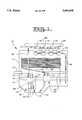
- FIG. 1is a schematic illustration of an engine according to a preferred embodiment of the present invention.
- an engine 10includes an engine casing 11.
- An oil pan 12, which is a portion of engine casing 11,is filled with an amount of lubricating oil 13 up to a level 14.
- Engine 10includes a conventional lubricating system that includes a low pressure pump 20 that is powered via a pump shaft 21 coupled in a known manner to the drive shaft 16 of the engine.
- Low pressure pump 20includes an inlet 22 that opens into the oil 13 in oil pan 12, and an outlet 23 that opens into circulation conduit 24 in a conventional manner.
- the lubricating oilpasses through a plurality of lubrication passages 25 that maintain the various moving parts within engine 10 properly lubricated. The oil then reconverges in a return conduit 26 and is circulated back to oil pan 12 in a conventional manner.
- the hydraulic systemincludes a high pressure pump 30 that is positioned in oil pan 12 and partially submerged in oil 13 such that at least a portion of the pump housing 34 is positioned below oil level 14.
- Pump 30is preferably a swash plate type pump having a plurality of parallel oriented pistons 35 that reciprocate as pump shaft 31 rotates. Pump shaft 31 is coupled to rotate with drive shaft 16 of engine 10 in a conventional manner.
- Inlet 32 of pump 30is positioned near the bottom of oil pan 12 in order to always be exposed to a ready supply of oil 13. Pressurized oil leaves pump 30 at outlet 33 and travels along high pressure supply pipe 40 to the inlet 41 of a high pressure manifold 42.
- High pressure manifold 42has a plurality of outlets 43, each of which is connected to a respective branch passage 48.
- the inlets 47 of a plurality of hydraulic devices 44are each connected to a separate branch passage 48.
- the hydraulic devices 44can include as examples hydraulically-actuated fuel injectors, exhaust brakes, intake or exhaust gas exchange valves, or any other suitable hydraulic device utilized by the engine during its operation.
- the drain ports 45 of the hydraulic devicesempty into a common return pipe 46 that returns the oil to oil pan 12 for recirculation.
- the present inventionachieves its goal of noise reduction by submerging the high pressure pump in an amount of oil that damps the noise produced during the normal operation of the pump. Additional noise attenuation is achieved by the enclosure of the high pressure pump in the oil pan. In prior art hydraulic systems, the high pressure pump was typically attached on the outside of the engine, and thus it radiated undesirable noise away from the engine. Those skilled in the art will appreciate that this noise reduction feature of the present invention could also be achieved by submerging the high pressure pump in oil at a location other than in the oil pan portion of the engine.
- the hydraulic systemBy positioning the inlet of the high pressure pump near the bottom of the oil pan, the hydraulic system is always exposed to a ready supply of oil, especially when the engine is undergoing a cold start condition.
- the inlet of the high pressure pumpwas exposed to a secondary reservoir located at a position well above the oil pan and supplied by the same low pressure pump that circulates the lubricating oil through the engine.
- the enginecould sometimes be required to crank excessively before the engine could start since the secondary reservoir would have to be substantially filled before the hydraulic system could have sufficient amounts of oil to draw upon for the necessary operation of the hydraulic devices.
- the present inventionovercomes this perceived irritation by always exposing the inlet of the high pressure pump to oil in the oil pan.
- this aspect of the present inventioncan be accomplished in other ways, including exposing the inlet of the high pressure pump to an oil compartment other than the oil pan that is positioned below the natural level 14 of the oil in the oil pan.
- the present inventionalso aids in streamlining engine packaging since a separate oil reservoir for the high pressure pump is no longer needed and the pump is now positioned within the engine casing as opposed to being attached to the outside surface of the engine as in the prior art.
- the engines incorporating the present inventionshould not only perform better than their prior art counterparts, but should also have the ability to occupy less space than their prior art counterparts. This permits engines according to the present invention to be positioned in confined spaces that might not otherwise be possible in prior art engines.
Landscapes
- Engineering & Computer Science (AREA)
- Mechanical Engineering (AREA)
- General Engineering & Computer Science (AREA)
- Chemical & Material Sciences (AREA)
- Combustion & Propulsion (AREA)
- Lubrication Of Internal Combustion Engines (AREA)
Abstract
Description
The present invention relates generally to engines that utilize hydraulic devices, and more particularly to an engine that utilizes a low pressure pump to circulate lubricating oil through the engine and a high pressure pump to pressurize the same oil to actuate hydraulic devices.
Engines have long utilized a variety of devices that draw power directly or indirectly from the engine for their operation. Among these devices are fuel injectors, gas intake and exhaust valves, exhaust brakes, etc. In the past, these devices were typically actuated by a cam that is driven directly by the engine. In order to improve engine performance across its operating spectrum, there has been a trend in the industry toward the adoption of electronically controlled hydraulic devices. An example of this trend is the hydraulically-actuated electronically-controlled unit injector (HEUI) system utilized by Caterpillar Inc. of Peoria, Ill. in their diesel engines.
In a typical HEUI system, a high pressure pump maintains a manifold at a relatively high pressure that is sufficient to actuate the hydraulic fuel injectors. The high pressure pump draws oil from a reservoir that is filled by the engine's low pressure oil circulation pump. After the high pressure oil is utilized by the fuel injectors, it is circulated back to the oil pan. Thus, a portion of the oil moved by the low pressure oil lubrication pump is circulated through the engine for lubrication, and another portion is pumped into the reservoir that supplies the high pressure pump.
In this current system, the high pressure pump is attached to the outside the engine, and thus any noise emitted from the pump is easily detectable. In addition, the reservoir that supplies the high pressure pump is above the engine's oil pan. This can result in excessive engine cranking from a cold start while the low pressure pump provides enough oil to the reservoir for the high pressure hydraulic system to achieve the relatively high pressures necessary for its operation. Not only does the high pressure pump tend to emit noise, but its location on the outside of the engine creates a protrusion that undermines the ability to position the engine in a confined space.
The present invention is directed to overcoming the engine packaging, noise reduction and other undesirable attributes associated with prior art engines that utilize hydraulic devices.
In one embodiment, an engine includes an engine housing. An oil lubricating system has a low pressure pump attached to the engine housing. A hydraulic system has a high pressure pump attached to the engine housing and is at least partially submerged in an amount of oil. In one aspect, the high pressure pump is positioned below the level of the oil in the engine's oil pan. In still another aspect, the high pressure pump is at least partially submerged in the oil within the oil pan.
FIG. 1 is a schematic illustration of an engine according to a preferred embodiment of the present invention.
Referring now to FIG. 1, anengine 10 includes anengine casing 11. Anoil pan 12, which is a portion ofengine casing 11, is filled with an amount of lubricatingoil 13 up to alevel 14.Engine 10 includes a conventional lubricating system that includes alow pressure pump 20 that is powered via apump shaft 21 coupled in a known manner to thedrive shaft 16 of the engine.Low pressure pump 20 includes aninlet 22 that opens into theoil 13 inoil pan 12, and anoutlet 23 that opens intocirculation conduit 24 in a conventional manner. After leaving circulation conduit 24, the lubricating oil passes through a plurality oflubrication passages 25 that maintain the various moving parts withinengine 10 properly lubricated. The oil then reconverges in areturn conduit 26 and is circulated back tooil pan 12 in a conventional manner.
Operating in parallel to the engine's lubricating system is a hydraulic system that utilizes the lubricatingoil 13 as a hydraulic medium in actuating a plurality ofhydraulic devices 44. The hydraulic system includes ahigh pressure pump 30 that is positioned inoil pan 12 and partially submerged inoil 13 such that at least a portion of thepump housing 34 is positioned belowoil level 14.Pump 30 is preferably a swash plate type pump having a plurality of paralleloriented pistons 35 that reciprocate aspump shaft 31 rotates.Pump shaft 31 is coupled to rotate withdrive shaft 16 ofengine 10 in a conventional manner.Inlet 32 ofpump 30 is positioned near the bottom ofoil pan 12 in order to always be exposed to a ready supply ofoil 13. Pressurizedoil leaves pump 30 atoutlet 33 and travels along highpressure supply pipe 40 to theinlet 41 of ahigh pressure manifold 42.
The present invention achieves its goal of noise reduction by submerging the high pressure pump in an amount of oil that damps the noise produced during the normal operation of the pump. Additional noise attenuation is achieved by the enclosure of the high pressure pump in the oil pan. In prior art hydraulic systems, the high pressure pump was typically attached on the outside of the engine, and thus it radiated undesirable noise away from the engine. Those skilled in the art will appreciate that this noise reduction feature of the present invention could also be achieved by submerging the high pressure pump in oil at a location other than in the oil pan portion of the engine.
By positioning the inlet of the high pressure pump near the bottom of the oil pan, the hydraulic system is always exposed to a ready supply of oil, especially when the engine is undergoing a cold start condition. In the past, the inlet of the high pressure pump was exposed to a secondary reservoir located at a position well above the oil pan and supplied by the same low pressure pump that circulates the lubricating oil through the engine. As a consequence, the engine could sometimes be required to crank excessively before the engine could start since the secondary reservoir would have to be substantially filled before the hydraulic system could have sufficient amounts of oil to draw upon for the necessary operation of the hydraulic devices. The present invention overcomes this perceived irritation by always exposing the inlet of the high pressure pump to oil in the oil pan. Those skilled in the art will appreciate that this aspect of the present invention can be accomplished in other ways, including exposing the inlet of the high pressure pump to an oil compartment other than the oil pan that is positioned below thenatural level 14 of the oil in the oil pan.
The present invention also aids in streamlining engine packaging since a separate oil reservoir for the high pressure pump is no longer needed and the pump is now positioned within the engine casing as opposed to being attached to the outside surface of the engine as in the prior art. Thus, the engines incorporating the present invention should not only perform better than their prior art counterparts, but should also have the ability to occupy less space than their prior art counterparts. This permits engines according to the present invention to be positioned in confined spaces that might not otherwise be possible in prior art engines.
The above description is intended for illustrative purposes only, and is not intended to limit the scope of the present invention in any way. For instance, while the low and high pressure oil circulation systems in the illustrated embodiment are shown to be completely parallel, those skilled in the art will appreciate that other variations might be possible. For instance, the excess pressure leaving the hydraulic devices could be harnessed to push oil through the lubricating passages of the engine before being returned to the oil pan. Thus, various modifications could be made to the illustrated embodiment without departing from the spirit and scope of the present invention, which is defined in terms of the claims as set forth below.
Claims (20)
1. An engine comprising:
an engine housing having an oil pan with an amount of oil therein;
an oil lubricating system having a low pressure pump attached to said engine housing;
a hydraulic system having a high pressure pump attached to said engine housing and being at least partially submerged in said amount of oil.
2. The engine of claim 1 wherein said hydraulic system includes a high pressure manifold and a plurality of hydraulic devices attached to said engine housing;
an inlet to said high pressure manifold being connected to an outlet from said high pressure pump; and
an outlet from said high pressure manifold being connected to an inlet of each of said plurality of hydraulic devices.
3. The engine of claim 2 wherein a portion of said plurality of hydraulic devices are fuel injectors.
4. The engine of claim 2 wherein a portion of said plurality of hydraulic devices are actuators for gas exchange valves or exhaust brakes.
5. The engine of claim 1 further comprising an engine drive shaft at least partially positioned in said engine housing;
said high pressure pump has a rotating shaft coupled to, and rotatable with, said engine drive shaft; and
said high pressure pump has a plurality of reciprocating pistons operably coupled to said rotating shaft.
6. The engine of claim 1 wherein said high pressure pump has an inlet that opens directly into said amount of oil.
7. An engine comprising:
an engine housing having an oil pan with oil therein up to a level;
an oil lubricating system having a low pressure pump attached to said engine housing;
a hydraulic system having a high pressure pump attached to said engine housing and being at least partially positioned below said level.
8. The engine of claim 7 wherein said high pressure pump is at least partially submerged in an amount of oil.
9. The engine of claim 8 wherein a portion of said high pressure pump is positioned in said oil pan.
10. The engine of claim 9 wherein said high pressure pump has an inlet that opens directly into said oil in said oil pan.
11. The engine of claim 10 further comprising an engine drive shaft at least partially positioned in said engine housing;
said high pressure pump has a rotating shaft coupled to, and rotatable with, said engine drive shaft; and
said high pressure pump has a plurality of reciprocating pistons operably coupled to said rotating shaft.
12. The engine of claim 11 wherein said hydraulic system includes a high pressure manifold and a plurality of hydraulic devices attached to said engine housing;
an inlet to said high pressure manifold being connected to an outlet from said high pressure pump; and
an outlet from said high pressure manifold being connected to an inlet of each of said plurality of hydraulic devices.
13. The engine of claim 12 wherein a portion of said plurality of hydraulic devices are fuel injectors.
14. The engine of claim 12 wherein a portion of said plurality of hydraulic devices are actuators for gas exchange valves or exhaust brakes.
15. An engine comprising:
an engine housing;
an oil lubricating system having a low pressure pump attached to said engine housing;
a hydraulic system having a high pressure pump attached to said engine housing and being at least partially submerged in an amount of oil.
16. The engine of claim 15 wherein said hydraulic system includes a high pressure manifold and a plurality of hydraulic devices attached to said engine housing;
an inlet to said high pressure manifold being connected to an outlet from said high pressure pump; and
an outlet from said high pressure manifold being connected to an inlet of each of said plurality of hydraulic devices.
17. The engine of claim 16 wherein said engine housing includes an oil pan having oil therein up to a level; and
a portion of said high pressure pump is positioned below said level.
18. The engine of claim 16 wherein a portion of said high pressure pump is positioned in said oil pan.
19. The engine of claim 18 wherein said high pressure pump has an inlet that opens directly into said oil in said oil pan.
20. The engine of claim 19 further comprising an engine drive shaft at least partially positioned in said engine housing;
said high pressure pump has a rotating shaft coupled to, and rotatable with, said engine drive shaft; and
said high pressure pump has a plurality of reciprocating pistons operably coupled to said rotating shaft.
Priority Applications (7)
| Application Number | Priority Date | Filing Date | Title |
|---|---|---|---|
| US08/990,584US5894830A (en) | 1997-12-15 | 1997-12-15 | Engine having a high pressure hydraulic system and low pressure lubricating system |
| GB9823519AGB2332240B (en) | 1997-12-15 | 1998-10-27 | Engine having a high pressure hydraulic system and low pressure lubricating system |
| US09/189,108US6067962A (en) | 1997-12-15 | 1998-11-10 | Engine having a high pressure hydraulic system and low pressure lubricating system |
| AU96094/98AAU737970B2 (en) | 1997-12-15 | 1998-12-07 | Engine having a high pressure hydraulic system and low pressure lubricating system |
| FR9815960AFR2772431B1 (en) | 1997-12-15 | 1998-12-15 | ENGINE COMPRISING A HIGH PRESSURE HYDRAULIC SYSTEM AND A LOW PRESSURE LUBRICATION SYSTEM |
| DE19857920ADE19857920A1 (en) | 1997-12-15 | 1998-12-15 | Engine with a high pressure hydraulic system and a low pressure lubrication system |
| JP10356103AJPH11257585A (en) | 1997-12-15 | 1998-12-15 | Engine |
Applications Claiming Priority (1)
| Application Number | Priority Date | Filing Date | Title |
|---|---|---|---|
| US08/990,584US5894830A (en) | 1997-12-15 | 1997-12-15 | Engine having a high pressure hydraulic system and low pressure lubricating system |
Related Child Applications (1)
| Application Number | Title | Priority Date | Filing Date |
|---|---|---|---|
| US09/189,108Continuation-In-PartUS6067962A (en) | 1997-12-15 | 1998-11-10 | Engine having a high pressure hydraulic system and low pressure lubricating system |
Publications (1)
| Publication Number | Publication Date |
|---|---|
| US5894830Atrue US5894830A (en) | 1999-04-20 |
Family
ID=25536298
Family Applications (1)
| Application Number | Title | Priority Date | Filing Date |
|---|---|---|---|
| US08/990,584Expired - Fee RelatedUS5894830A (en) | 1997-12-15 | 1997-12-15 | Engine having a high pressure hydraulic system and low pressure lubricating system |
Country Status (6)
| Country | Link |
|---|---|
| US (1) | US5894830A (en) |
| JP (1) | JPH11257585A (en) |
| AU (1) | AU737970B2 (en) |
| DE (1) | DE19857920A1 (en) |
| FR (1) | FR2772431B1 (en) |
| GB (1) | GB2332240B (en) |
Cited By (15)
| Publication number | Priority date | Publication date | Assignee | Title |
|---|---|---|---|---|
| US6041752A (en)* | 1998-11-04 | 2000-03-28 | Technology Holdings, Inc. | Moldable integrated oil pan and suction tube for an internal combustion engine |
| WO2000028193A1 (en)* | 1998-11-10 | 2000-05-18 | Caterpillar Inc. | Engine having a high pressure hydraulic system and low pressure lubricating system |
| US6148805A (en)* | 1998-12-15 | 2000-11-21 | Caterpillar Inc. | Engine with hydraulic fuel injection and EGR valve using a single high pressure pump |
| US6261069B1 (en)* | 2000-03-08 | 2001-07-17 | Stanadyne Automotive Corp. | Shaft seal with pressure equalizing shuttle |
| US6283090B1 (en)* | 1999-11-17 | 2001-09-04 | Caterpillar Inc. | Method and apparatus for operating a hydraulically-powered compression release brake assembly on internal combustion engine |
| US6289878B1 (en)* | 1999-07-15 | 2001-09-18 | Caterpillar Inc. | Engine having multiple pumps driven by a single shaft |
| US6330875B1 (en) | 1999-12-16 | 2001-12-18 | Caterpillar Inc. | Engine with hydraulic fuel injection and ABS circuit using a single high pressure pump |
| GR1003820B (en)* | 2001-05-18 | 2002-02-21 | System for electrical - hydraulic movement of valves | |
| US6405707B1 (en)* | 2000-12-18 | 2002-06-18 | Caterpillar Inc. | Integral engine and engine compression braking HEUI injector |
| WO2002081875A1 (en)* | 2001-04-06 | 2002-10-17 | Robert Bosch Gmbh | Internal combustion engine comprising a hydraulic system |
| WO2003002876A1 (en)* | 2001-06-27 | 2003-01-09 | Karasawa Fine., Ltd | Booster |
| WO2007138633A1 (en)* | 2006-05-31 | 2007-12-06 | La.Me. S.R.L. | Positive displacement piston pump, for lubrication |
| CN103277165A (en)* | 2013-05-08 | 2013-09-04 | 祥天控股(集团)有限公司 | Oil way system of rotary type engine |
| CN104197174A (en)* | 2014-08-26 | 2014-12-10 | 无锡市胜艺粉体机械设备厂 | Oil lubrication device for spray dryer |
| CN105465584A (en)* | 2015-12-22 | 2016-04-06 | 武汉船用机械有限责任公司 | Self-lubricating felt of gear-rack jacking system |
Families Citing this family (35)
| Publication number | Priority date | Publication date | Assignee | Title |
|---|---|---|---|---|
| JP6259688B2 (en)* | 2014-03-14 | 2018-01-10 | 大豊工業株式会社 | Lubricating oil supply mechanism |
| US11624326B2 (en) | 2017-05-21 | 2023-04-11 | Bj Energy Solutions, Llc | Methods and systems for supplying fuel to gas turbine engines |
| US11560845B2 (en) | 2019-05-15 | 2023-01-24 | Bj Energy Solutions, Llc | Mobile gas turbine inlet air conditioning system and associated methods |
| US12065968B2 (en) | 2019-09-13 | 2024-08-20 | BJ Energy Solutions, Inc. | Systems and methods for hydraulic fracturing |
| US10961914B1 (en) | 2019-09-13 | 2021-03-30 | BJ Energy Solutions, LLC Houston | Turbine engine exhaust duct system and methods for noise dampening and attenuation |
| US10895202B1 (en) | 2019-09-13 | 2021-01-19 | Bj Energy Solutions, Llc | Direct drive unit removal system and associated methods |
| US12338772B2 (en) | 2019-09-13 | 2025-06-24 | Bj Energy Solutions, Llc | Systems, assemblies, and methods to enhance intake air flow to a gas turbine engine of a hydraulic fracturing unit |
| CA3092863C (en) | 2019-09-13 | 2023-07-18 | Bj Energy Solutions, Llc | Fuel, communications, and power connection systems and related methods |
| CA3197583A1 (en) | 2019-09-13 | 2021-03-13 | Bj Energy Solutions, Llc | Fuel, communications, and power connection systems and related methods |
| US11604113B2 (en) | 2019-09-13 | 2023-03-14 | Bj Energy Solutions, Llc | Fuel, communications, and power connection systems and related methods |
| CA3092865C (en) | 2019-09-13 | 2023-07-04 | Bj Energy Solutions, Llc | Power sources and transmission networks for auxiliary equipment onboard hydraulic fracturing units and associated methods |
| US11002189B2 (en) | 2019-09-13 | 2021-05-11 | Bj Energy Solutions, Llc | Mobile gas turbine inlet air conditioning system and associated methods |
| US11015594B2 (en) | 2019-09-13 | 2021-05-25 | Bj Energy Solutions, Llc | Systems and method for use of single mass flywheel alongside torsional vibration damper assembly for single acting reciprocating pump |
| CA3092829C (en) | 2019-09-13 | 2023-08-15 | Bj Energy Solutions, Llc | Methods and systems for supplying fuel to gas turbine engines |
| US10815764B1 (en) | 2019-09-13 | 2020-10-27 | Bj Energy Solutions, Llc | Methods and systems for operating a fleet of pumps |
| US11708829B2 (en) | 2020-05-12 | 2023-07-25 | Bj Energy Solutions, Llc | Cover for fluid systems and related methods |
| US10968837B1 (en) | 2020-05-14 | 2021-04-06 | Bj Energy Solutions, Llc | Systems and methods utilizing turbine compressor discharge for hydrostatic manifold purge |
| US11428165B2 (en) | 2020-05-15 | 2022-08-30 | Bj Energy Solutions, Llc | Onboard heater of auxiliary systems using exhaust gases and associated methods |
| US11208880B2 (en) | 2020-05-28 | 2021-12-28 | Bj Energy Solutions, Llc | Bi-fuel reciprocating engine to power direct drive turbine fracturing pumps onboard auxiliary systems and related methods |
| US11109508B1 (en) | 2020-06-05 | 2021-08-31 | Bj Energy Solutions, Llc | Enclosure assembly for enhanced cooling of direct drive unit and related methods |
| US11208953B1 (en) | 2020-06-05 | 2021-12-28 | Bj Energy Solutions, Llc | Systems and methods to enhance intake air flow to a gas turbine engine of a hydraulic fracturing unit |
| US10954770B1 (en) | 2020-06-09 | 2021-03-23 | Bj Energy Solutions, Llc | Systems and methods for exchanging fracturing components of a hydraulic fracturing unit |
| US11111768B1 (en) | 2020-06-09 | 2021-09-07 | Bj Energy Solutions, Llc | Drive equipment and methods for mobile fracturing transportation platforms |
| US11066915B1 (en) | 2020-06-09 | 2021-07-20 | Bj Energy Solutions, Llc | Methods for detection and mitigation of well screen out |
| US11028677B1 (en) | 2020-06-22 | 2021-06-08 | Bj Energy Solutions, Llc | Stage profiles for operations of hydraulic systems and associated methods |
| US11933153B2 (en) | 2020-06-22 | 2024-03-19 | Bj Energy Solutions, Llc | Systems and methods to operate hydraulic fracturing units using automatic flow rate and/or pressure control |
| US11939853B2 (en) | 2020-06-22 | 2024-03-26 | Bj Energy Solutions, Llc | Systems and methods providing a configurable staged rate increase function to operate hydraulic fracturing units |
| US11125066B1 (en) | 2020-06-22 | 2021-09-21 | Bj Energy Solutions, Llc | Systems and methods to operate a dual-shaft gas turbine engine for hydraulic fracturing |
| US11466680B2 (en) | 2020-06-23 | 2022-10-11 | Bj Energy Solutions, Llc | Systems and methods of utilization of a hydraulic fracturing unit profile to operate hydraulic fracturing units |
| US11473413B2 (en) | 2020-06-23 | 2022-10-18 | Bj Energy Solutions, Llc | Systems and methods to autonomously operate hydraulic fracturing units |
| US11220895B1 (en) | 2020-06-24 | 2022-01-11 | Bj Energy Solutions, Llc | Automated diagnostics of electronic instrumentation in a system for fracturing a well and associated methods |
| US11149533B1 (en) | 2020-06-24 | 2021-10-19 | Bj Energy Solutions, Llc | Systems to monitor, detect, and/or intervene relative to cavitation and pulsation events during a hydraulic fracturing operation |
| US11193360B1 (en) | 2020-07-17 | 2021-12-07 | Bj Energy Solutions, Llc | Methods, systems, and devices to enhance fracturing fluid delivery to subsurface formations during high-pressure fracturing operations |
| US11639654B2 (en) | 2021-05-24 | 2023-05-02 | Bj Energy Solutions, Llc | Hydraulic fracturing pumps to enhance flow of fracturing fluid into wellheads and related methods |
| CA3180024A1 (en) | 2021-10-25 | 2023-04-25 | Bj Energy Solutions, Llc | Systems and methods to reduce acoustic resonance or disrupt standing wave formation in a fluid manifold of a high-pressure fracturing system |
Citations (18)
| Publication number | Priority date | Publication date | Assignee | Title |
|---|---|---|---|---|
| US4305367A (en)* | 1978-08-31 | 1981-12-15 | Hino Jidosha Kogyo Kabushiki Kaisha | Injection timing control system for fuel-injection pump for engine |
| US4373483A (en)* | 1980-03-19 | 1983-02-15 | David Brown Tractors Ltd. | Lubricating oil pump drive for an internal combustion engine |
| US4436067A (en)* | 1980-11-25 | 1984-03-13 | Bayerische Motoren Werke Aktiengesellschaft | Engine driven pump arrangement |
| US4586468A (en)* | 1984-10-05 | 1986-05-06 | General Motors Corporation | Tandem pump assembly |
| US4648363A (en)* | 1985-11-12 | 1987-03-10 | Tecumseh Products Company | Lubricating oil filtration system for an engine |
| US4653448A (en)* | 1984-02-22 | 1987-03-31 | Nippondenso Co., Ltd. | Fuel injection device |
| US4721185A (en)* | 1985-05-09 | 1988-01-26 | Robert Bosch Gmbh | Oil container arrangement for vehicles |
| US4974562A (en)* | 1988-12-27 | 1990-12-04 | Fuji Jukogyo Kabushiki Kaisha | Oil pump device of an engine |
| US5063895A (en)* | 1989-07-01 | 1991-11-12 | Dr. Ing. H.C.F. Porsche Ag | Oil pump drive arrangement for a piston internal-combustion engine and method of making same |
| US5085768A (en)* | 1988-03-09 | 1992-02-04 | Mitsubishi Denki Kabushiki Kaisha | Welded fuel tank |
| US5245970A (en)* | 1992-09-04 | 1993-09-21 | Navistar International Transportation Corp. | Priming reservoir and volume compensation device for hydraulic unit injector fuel system |
| US5271360A (en)* | 1990-11-08 | 1993-12-21 | Aisin Seiki Kabushiki Kaisha | Valve opening and closing timing control apparatus |
| US5479901A (en)* | 1994-06-27 | 1996-01-02 | Caterpillar Inc. | Electro-hydraulic spool control valve assembly adapted for a fuel injector |
| US5515829A (en)* | 1994-05-20 | 1996-05-14 | Caterpillar Inc. | Variable-displacement actuating fluid pump for a HEUI fuel system |
| US5606943A (en)* | 1993-11-12 | 1997-03-04 | Kawasaki Jukogyo Kabushiki Kaisha | Four-cycle engine |
| US5725361A (en)* | 1993-02-02 | 1998-03-10 | Mannesmann Rexroth Gmbh | Hydraulic unit |
| US5769182A (en)* | 1993-10-13 | 1998-06-23 | Kvaerner Hymac Inc. | Lubricant supply safety system |
| US5816212A (en)* | 1996-05-17 | 1998-10-06 | Man B & W Diesel A/S | Oil supply device |
Family Cites Families (3)
| Publication number | Priority date | Publication date | Assignee | Title |
|---|---|---|---|---|
| GB562487A (en)* | 1942-04-27 | 1944-07-04 | Century Motors Corp | Improvements in or relating to the lubrication of internal combustion engines |
| US5787863A (en)* | 1996-01-23 | 1998-08-04 | Caterpillar Inc. | Fuel system having priming actuating fluid accumulator |
| US5682851A (en)* | 1996-11-14 | 1997-11-04 | Caterpillar Inc. | Oil system for an engine that includes an auxiliary priming pump |
- 1997
- 1997-12-15USUS08/990,584patent/US5894830A/ennot_activeExpired - Fee Related
- 1998
- 1998-10-27GBGB9823519Apatent/GB2332240B/ennot_activeExpired - Fee Related
- 1998-12-07AUAU96094/98Apatent/AU737970B2/ennot_activeCeased
- 1998-12-15JPJP10356103Apatent/JPH11257585A/enactivePending
- 1998-12-15FRFR9815960Apatent/FR2772431B1/ennot_activeExpired - Fee Related
- 1998-12-15DEDE19857920Apatent/DE19857920A1/ennot_activeWithdrawn
Patent Citations (18)
| Publication number | Priority date | Publication date | Assignee | Title |
|---|---|---|---|---|
| US4305367A (en)* | 1978-08-31 | 1981-12-15 | Hino Jidosha Kogyo Kabushiki Kaisha | Injection timing control system for fuel-injection pump for engine |
| US4373483A (en)* | 1980-03-19 | 1983-02-15 | David Brown Tractors Ltd. | Lubricating oil pump drive for an internal combustion engine |
| US4436067A (en)* | 1980-11-25 | 1984-03-13 | Bayerische Motoren Werke Aktiengesellschaft | Engine driven pump arrangement |
| US4653448A (en)* | 1984-02-22 | 1987-03-31 | Nippondenso Co., Ltd. | Fuel injection device |
| US4586468A (en)* | 1984-10-05 | 1986-05-06 | General Motors Corporation | Tandem pump assembly |
| US4721185A (en)* | 1985-05-09 | 1988-01-26 | Robert Bosch Gmbh | Oil container arrangement for vehicles |
| US4648363A (en)* | 1985-11-12 | 1987-03-10 | Tecumseh Products Company | Lubricating oil filtration system for an engine |
| US5085768A (en)* | 1988-03-09 | 1992-02-04 | Mitsubishi Denki Kabushiki Kaisha | Welded fuel tank |
| US4974562A (en)* | 1988-12-27 | 1990-12-04 | Fuji Jukogyo Kabushiki Kaisha | Oil pump device of an engine |
| US5063895A (en)* | 1989-07-01 | 1991-11-12 | Dr. Ing. H.C.F. Porsche Ag | Oil pump drive arrangement for a piston internal-combustion engine and method of making same |
| US5271360A (en)* | 1990-11-08 | 1993-12-21 | Aisin Seiki Kabushiki Kaisha | Valve opening and closing timing control apparatus |
| US5245970A (en)* | 1992-09-04 | 1993-09-21 | Navistar International Transportation Corp. | Priming reservoir and volume compensation device for hydraulic unit injector fuel system |
| US5725361A (en)* | 1993-02-02 | 1998-03-10 | Mannesmann Rexroth Gmbh | Hydraulic unit |
| US5769182A (en)* | 1993-10-13 | 1998-06-23 | Kvaerner Hymac Inc. | Lubricant supply safety system |
| US5606943A (en)* | 1993-11-12 | 1997-03-04 | Kawasaki Jukogyo Kabushiki Kaisha | Four-cycle engine |
| US5515829A (en)* | 1994-05-20 | 1996-05-14 | Caterpillar Inc. | Variable-displacement actuating fluid pump for a HEUI fuel system |
| US5479901A (en)* | 1994-06-27 | 1996-01-02 | Caterpillar Inc. | Electro-hydraulic spool control valve assembly adapted for a fuel injector |
| US5816212A (en)* | 1996-05-17 | 1998-10-06 | Man B & W Diesel A/S | Oil supply device |
Cited By (21)
| Publication number | Priority date | Publication date | Assignee | Title |
|---|---|---|---|---|
| US6041752A (en)* | 1998-11-04 | 2000-03-28 | Technology Holdings, Inc. | Moldable integrated oil pan and suction tube for an internal combustion engine |
| WO2000028193A1 (en)* | 1998-11-10 | 2000-05-18 | Caterpillar Inc. | Engine having a high pressure hydraulic system and low pressure lubricating system |
| US6148805A (en)* | 1998-12-15 | 2000-11-21 | Caterpillar Inc. | Engine with hydraulic fuel injection and EGR valve using a single high pressure pump |
| US6289878B1 (en)* | 1999-07-15 | 2001-09-18 | Caterpillar Inc. | Engine having multiple pumps driven by a single shaft |
| US6283090B1 (en)* | 1999-11-17 | 2001-09-04 | Caterpillar Inc. | Method and apparatus for operating a hydraulically-powered compression release brake assembly on internal combustion engine |
| US6330875B1 (en) | 1999-12-16 | 2001-12-18 | Caterpillar Inc. | Engine with hydraulic fuel injection and ABS circuit using a single high pressure pump |
| US6261069B1 (en)* | 2000-03-08 | 2001-07-17 | Stanadyne Automotive Corp. | Shaft seal with pressure equalizing shuttle |
| US6405707B1 (en)* | 2000-12-18 | 2002-06-18 | Caterpillar Inc. | Integral engine and engine compression braking HEUI injector |
| US20030188702A1 (en)* | 2001-04-06 | 2003-10-09 | Hermann Gaessler | Internal combustion engine comprising a hydraulic system |
| US6854431B2 (en) | 2001-04-06 | 2005-02-15 | Robert Bosch Gmbh | Internal combustion engine comprising a hydraulic system |
| WO2002081875A1 (en)* | 2001-04-06 | 2002-10-17 | Robert Bosch Gmbh | Internal combustion engine comprising a hydraulic system |
| WO2002095195A1 (en)* | 2001-05-18 | 2002-11-28 | Spyridon Pappas | System for electrical - hydraulic movement of valves |
| GR1003820B (en)* | 2001-05-18 | 2002-02-21 | System for electrical - hydraulic movement of valves | |
| WO2003002876A1 (en)* | 2001-06-27 | 2003-01-09 | Karasawa Fine., Ltd | Booster |
| WO2007138633A1 (en)* | 2006-05-31 | 2007-12-06 | La.Me. S.R.L. | Positive displacement piston pump, for lubrication |
| US20090191075A1 (en)* | 2006-05-31 | 2009-07-30 | La.Me S.R.L. | Positive displacement piston pump, for lubication |
| CN103277165A (en)* | 2013-05-08 | 2013-09-04 | 祥天控股(集团)有限公司 | Oil way system of rotary type engine |
| CN104197174A (en)* | 2014-08-26 | 2014-12-10 | 无锡市胜艺粉体机械设备厂 | Oil lubrication device for spray dryer |
| CN104197174B (en)* | 2014-08-26 | 2016-05-04 | 无锡市胜艺粉体机械设备厂 | The oil lubrication device of spray dryer |
| CN105465584A (en)* | 2015-12-22 | 2016-04-06 | 武汉船用机械有限责任公司 | Self-lubricating felt of gear-rack jacking system |
| CN105465584B (en)* | 2015-12-22 | 2018-02-13 | 武汉船用机械有限责任公司 | A kind of self-lubricating felt of gear rack lifting system |
Also Published As
| Publication number | Publication date |
|---|---|
| GB2332240B (en) | 2001-10-03 |
| FR2772431A1 (en) | 1999-06-18 |
| FR2772431B1 (en) | 2002-03-01 |
| JPH11257585A (en) | 1999-09-21 |
| GB2332240A (en) | 1999-06-16 |
| AU9609498A (en) | 1999-07-01 |
| GB9823519D0 (en) | 1998-12-23 |
| DE19857920A1 (en) | 1999-06-17 |
| AU737970B2 (en) | 2001-09-06 |
Similar Documents
| Publication | Publication Date | Title |
|---|---|---|
| US5894830A (en) | Engine having a high pressure hydraulic system and low pressure lubricating system | |
| US6067962A (en) | Engine having a high pressure hydraulic system and low pressure lubricating system | |
| US6848423B2 (en) | Fuel injection system for an internal combustion engine | |
| JP3915718B2 (en) | Fuel supply pump | |
| US6823845B2 (en) | Fuel injection system with improved regulation of pumping quantities | |
| US6647938B2 (en) | Supply pressure pump with separate drive on an internal combustion engine | |
| US6021761A (en) | High-pressure pump for fuel delivery in fuel injection systems of internal combustion engines | |
| JPH0814140A (en) | High pressure supply pump | |
| US7823545B2 (en) | Piston squirter system and method | |
| US5682851A (en) | Oil system for an engine that includes an auxiliary priming pump | |
| JP2003206824A (en) | Injection pump, dme fuel supply device of diesel engine having it | |
| JP2014517201A (en) | Fuel system and method for reducing fuel leakage from a fuel system | |
| US6866025B1 (en) | High pressure fuel pump delivery control by piston deactivation | |
| US7137789B2 (en) | Vent for reducing seal pressure in pump assembly | |
| US6450146B1 (en) | High pressure pump with a close-mounted valve for a hydraulic fuel system | |
| US6289878B1 (en) | Engine having multiple pumps driven by a single shaft | |
| US4527520A (en) | Lubrication of an ancillary pump fitted to an engine | |
| JPH034780Y2 (en) | ||
| US6460503B2 (en) | Oil pump layout structure for internal combustion engine | |
| US6142110A (en) | Engine having hydraulic and fan drive systems using a single high pressure pump | |
| US6220521B1 (en) | Vehicle hydraulic system that provides heat for passenger compartment | |
| US6464473B2 (en) | Pump apparatus for hydraulically powered fuel injection systems | |
| JPH08121133A (en) | Two cycle fuel injection engine | |
| JP2009197659A (en) | Manifold integrated type oil tank module | |
| US6854431B2 (en) | Internal combustion engine comprising a hydraulic system |
Legal Events
| Date | Code | Title | Description |
|---|---|---|---|
| AS | Assignment | Owner name:CATERPILLAR INC., ILLINOIS Free format text:ASSIGNMENT OF ASSIGNORS INTEREST;ASSIGNORS:BLASS, JAMES R.;GIBSON, DENNIS H.;MESSINGER, DEAN D.;AND OTHERS;REEL/FRAME:008913/0443;SIGNING DATES FROM 19971209 TO 19971212 | |
| FPAY | Fee payment | Year of fee payment:4 | |
| FPAY | Fee payment | Year of fee payment:8 | |
| REMI | Maintenance fee reminder mailed | ||
| LAPS | Lapse for failure to pay maintenance fees | ||
| STCH | Information on status: patent discontinuation | Free format text:PATENT EXPIRED DUE TO NONPAYMENT OF MAINTENANCE FEES UNDER 37 CFR 1.362 | |
| FP | Lapsed due to failure to pay maintenance fee | Effective date:20110420 |