US5894540A - Optical Fiber take-up assembly - Google Patents
Optical Fiber take-up assemblyDownload PDFInfo
- Publication number
- US5894540A US5894540AUS08/862,014US86201497AUS5894540AUS 5894540 AUS5894540 AUS 5894540AUS 86201497 AUS86201497 AUS 86201497AUS 5894540 AUS5894540 AUS 5894540A
- Authority
- US
- United States
- Prior art keywords
- spools
- pair
- support plate
- filamentary material
- slack
- Prior art date
- Legal status (The legal status is an assumption and is not a legal conclusion. Google has not performed a legal analysis and makes no representation as to the accuracy of the status listed.)
- Expired - Fee Related
Links
- 239000013307optical fiberSubstances0.000titleabstractdescription15
- 239000000463materialSubstances0.000claimsdescription10
- 238000000034methodMethods0.000claimsdescription4
- 230000013011matingEffects0.000claimsdescription3
- 239000000835fiberSubstances0.000abstractdescription32
- 230000001012protectorEffects0.000abstractdescription15
- 230000004927fusionEffects0.000abstractdescription8
- 230000006978adaptationEffects0.000description1
- 230000000712assemblyEffects0.000description1
- 238000000429assemblyMethods0.000description1
- 230000000694effectsEffects0.000description1
- 238000012986modificationMethods0.000description1
- 230000004048modificationEffects0.000description1
- 230000008054signal transmissionEffects0.000description1
Images


Classifications
- G—PHYSICS
- G02—OPTICS
- G02B—OPTICAL ELEMENTS, SYSTEMS OR APPARATUS
- G02B6/00—Light guides; Structural details of arrangements comprising light guides and other optical elements, e.g. couplings
- G02B6/44—Mechanical structures for providing tensile strength and external protection for fibres, e.g. optical transmission cables
- G02B6/4439—Auxiliary devices
- G02B6/4457—Bobbins; Reels
- G—PHYSICS
- G02—OPTICS
- G02B—OPTICAL ELEMENTS, SYSTEMS OR APPARATUS
- G02B6/00—Light guides; Structural details of arrangements comprising light guides and other optical elements, e.g. couplings
- G02B6/44—Mechanical structures for providing tensile strength and external protection for fibres, e.g. optical transmission cables
- G02B6/4439—Auxiliary devices
- G02B6/444—Systems or boxes with surplus lengths
- G02B6/4452—Distribution frames
- G02B6/44524—Distribution frames with frame parts or auxiliary devices mounted on the frame and collectively not covering a whole width of the frame or rack
- G—PHYSICS
- G02—OPTICS
- G02B—OPTICAL ELEMENTS, SYSTEMS OR APPARATUS
- G02B6/00—Light guides; Structural details of arrangements comprising light guides and other optical elements, e.g. couplings
- G02B6/44—Mechanical structures for providing tensile strength and external protection for fibres, e.g. optical transmission cables
- G02B6/4439—Auxiliary devices
- G02B6/444—Systems or boxes with surplus lengths
- G02B6/4453—Cassettes
Definitions
- This inventionrelates to an assembly for storing a length of optical fiber between its connected ends and, more particularly, to such an assembly which stores the fiber securely without slack and accommodates a rigid splice protector therein.
- Individual optical fibers used for interconnecting electro-optical modulesare typically provided as "pig tail" assemblies extending out of the respective modules.
- the field installermakes a fusion splice of a pair of the fibers and covers the splice with a rigid splice protection sleeve.
- the spliced fiberthen has a strain relief boot (part of the pig tail) at each end for interconnecting two electro-optical modules. When this is done, there will be a length of loose fiber which must be stored in some manner for protection.
- Splice trays or boxesare presently available which contain clips into which the splice protection sleeve can be inserted, and the excess fiber is then looped in the tray.
- optical fibersmust be maintained with a minimum bend radius to avoid signal loss. Accordingly, any such excess fiber storage assembly must meet the minimum bend radius requirement.
- an assemblyfor holding a length of filamentary material, in particular an optical fiber having a rigid fusion splice protector, in a wrapped configuration with a minimum bend radius.
- the assemblycomprises a support plate and at least two spools.
- Each of the spoolshas a radius of at least the minimum bend radius and each of the spools subtends an arc of at least 180°.
- mounting structureAssociated with the support plate and the spools is mounting structure adapted to secure the spools to the support plate with the center of radius of each of the spools lying along a straight line.
- the mounting structureis also adapted to allow selective adjustment of the spacing between the spools.
- the fibercan be wrapped around the spools and the spacing between the spools can be adjusted so as to take up the slack in the fiber. Since the rigid fusion splice protector must be positioned along a straight length of the fiber between the spools during the wrapping process, the spool spacing adjustability is utilized to effect this positioning.
- FIG. 1is a perspective view showing an optical fiber with a fusion splice protector interconnecting a pair of electro-optical modules;
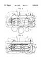
- FIG. 2is an exploded perspective view of an optical fiber take-up assembly constructed in accordance with the principles of this invention.
- FIGS. 3-5illustrate steps in the wrapping of an optical fiber on the inventive assembly.
- FIG. 1illustrates a pair of electro-optical modules 10, 12 supported on, and preferably secured to, the shelf 14.
- the modules 10, 12are interconnected by an optical fiber 16 terminated by the strain relief boots 18, 20 and having a rigid fusion splice protector 22 covering a fusion splice along its length.
- excess fiberis loosely draped between the entries into the modules 10, 12.
- the optical fiber 16is relatively fragile and the excess fiber must be properly stored to prevent it from being damaged. In addition, such storage must take place with minimum bend radius of the fiber to avoid signal transmission losses therethrough.
- the inventive take-up assembly shown in FIG. 2provides secure, robust, vibration resistant storage for the excess optical fiber while maintaining a minimum bend radius for the fiber.
- the assemblyincludes a support plate 24 preferably secured to the front face of the shelf 14 by screws 26 extending through apertures 28 in the corners of the support plate 24.
- the assemblyfurther includes a plurality of spools, illustratively four in number, 30, 32, 34, 36, each of which has a radius to its fiber support surface of at least the minimum bend radius of the fiber 16.
- Each of the spools 30, 32, 34, 36subtends an arc of at least 180°.
- each of the spools 30, 32, 34, 36subtends exactly a 180° arc.
- Mounting structureis provided for securing the spools 30, 32, 34, 36 to the support plate 24. This mounting structure aligns the spools 30, 32, 34, 36 with their centers of radius lying along a straight line and allows selective adjustment of the spacing between the spools 30, 32, 34, 36.
- the illustrative mounting structureincludes a pair of rails on the support plate 24 extending parallel to the straight line passing through the centers of radius of the spools.
- the pair of railsare in the form of a pair of elongated slots 38, 40 through the support plate 24.
- Each of the spools 30, 32, 34, 36is formed with a pair of apertures 42 along a line which is orthogonal to a radius of the respective spool which bisects the arc subtended by that spool.
- each fastenerillustratively being a threaded rod 44 having an enlarged head 46 at one end and a mating nut 48 threaded thereon at the other end.
- the rod 44passes through one of the slots 38, 40 and one of the apertures 42 so that the respective one of the spools 30, 32, 34, 36 is clamped to the support plate 24 between the head 46 and the nut 48.
- FIGS. 3-5illustrate the wrapping of the fiber 16 around the spools 30, 32, 34, 36.
- the fiber 16is wrapped around the periphery of the spool 30 without slack.
- the mounting of the outer spools 30, 36is such that they are oriented with their subtended arcs providing at least 180° of subtended arc for wrapping the fiber 16 at opposite ends of the assembly.
- the splice protector 22is rigid, it cannot be wrapped around one of the spools, since it is not conformable to the curvature of the fiber support surface of the spool. Accordingly, the rigid splice protector 22 must be positioned along a straight length of the fiber 16 between a pair of the spools. If the initial wrapping results in the splice protector 22 falling on the periphery of one of the spools 30, 36, the spacing between the spools 30, 36 is adjusted and the wrapping redone until the splice protector 22 is where it should be, as shown in FIG. 4. The wrapping then continues until a final complete wrap cannot be attained around the outer spools 30, 36. This is when the intermediate spools 32, 34 become of use. The remaining fiber is wrapped around the spools 32, 34 and around the spool 36 with some slack, and then the positions of the intermediate spools 32, 34 are adjusted to take up all such slack, as shown in FIG. 5.
- the aforedescribed wrapping procedureis one of trial and error, requiring that the positions of the spools 30, 32, 34, 36 be adjusted until the fiber 16 is wrapped without any slack and the rigid splice protector 22 is properly positioned.
- the nuts 48are then tightened on the rods 44.
- Thisprovides a robust, rugged and vibration resistant solution to the problem of holding excess fiber. Because the fiber 16 is held without slack, it is maintained in place between the flanges of the spools 30, 32, 34, 36.
- the aforedescribed assemblyprovides a low profile excess fiber storage facility which is useful in confined spaces.
- the described take-up assemblyhas been shown as being in a generally vertical plane with the optical fiber exiting the modules generally horizontally, it will be appreciated that a minimum bend radius of the fiber must be maintained over its entire length. Therefore, in actual practice, either the take-up assembly will be in the same plane as the fibers exiting the modules or there will be provided a bend limiter (such as a spool) between each strain relief boot and the take-up assembly.
- a bend limitersuch as a spool
Landscapes
- Physics & Mathematics (AREA)
- General Physics & Mathematics (AREA)
- Optics & Photonics (AREA)
- Light Guides In General And Applications Therefor (AREA)
Abstract
Description
Claims (8)
Priority Applications (1)
| Application Number | Priority Date | Filing Date | Title |
|---|---|---|---|
| US08/862,014US5894540A (en) | 1997-05-22 | 1997-05-22 | Optical Fiber take-up assembly |
Applications Claiming Priority (1)
| Application Number | Priority Date | Filing Date | Title |
|---|---|---|---|
| US08/862,014US5894540A (en) | 1997-05-22 | 1997-05-22 | Optical Fiber take-up assembly |
Publications (1)
| Publication Number | Publication Date |
|---|---|
| US5894540Atrue US5894540A (en) | 1999-04-13 |
Family
ID=25337399
Family Applications (1)
| Application Number | Title | Priority Date | Filing Date |
|---|---|---|---|
| US08/862,014Expired - Fee RelatedUS5894540A (en) | 1997-05-22 | 1997-05-22 | Optical Fiber take-up assembly |
Country Status (1)
| Country | Link |
|---|---|
| US (1) | US5894540A (en) |
Cited By (73)
| Publication number | Priority date | Publication date | Assignee | Title |
|---|---|---|---|---|
| US6160946A (en)* | 1998-07-27 | 2000-12-12 | Adc Telecommunications, Inc. | Outside plant fiber distribution apparatus and method |
| US6361360B1 (en)* | 2000-09-26 | 2002-03-26 | Agilent Technologies, Inc. | Expandable strain relief for flexible cable-like members |
| WO2002072496A1 (en) | 2001-03-13 | 2002-09-19 | 3M Innovative Properties Company | Filament recoating apparatus and method |
| WO2002073273A1 (en)* | 2001-03-13 | 2002-09-19 | 3M Innovative Properties Company | Filament organizer |
| WO2002072497A1 (en) | 2001-03-13 | 2002-09-19 | 3M Innovative Properties Company | Filament recoating apparatus and method |
| US6487939B1 (en) | 2001-03-13 | 2002-12-03 | 3M Innovative Properties Company | Apparatus and method for removing coatings from filaments |
| US6532327B1 (en) | 2001-03-13 | 2003-03-11 | 3M Innovative Properties Company | Refractive index grating manufacturing process |
| US6533205B1 (en)* | 2001-08-31 | 2003-03-18 | Stocker Yale, Inc. | Fiber optic cable winding tool |
| US6547920B2 (en) | 2001-03-13 | 2003-04-15 | 3M Innovative Properties | Chemical stripping apparatus and method |
| US20030161607A1 (en)* | 2002-02-27 | 2003-08-28 | Lin Kon Mang | Jumper cable module |
| US20030169993A1 (en)* | 2000-05-31 | 2003-09-11 | D'inca Claudio | Optical assembly |
| US6665483B2 (en) | 2001-03-13 | 2003-12-16 | 3M Innovative Properties Company | Apparatus and method for filament tensioning |
| WO2003085421A3 (en)* | 2002-04-10 | 2003-12-18 | Corvis Corp | Optical fiber device manufacturing systems, apparatuses, and methods |
| US6669129B1 (en)* | 2001-08-31 | 2003-12-30 | Stocker Yale, Inc. | Fiber optic cable winding tool |
| US20050213921A1 (en)* | 2004-03-08 | 2005-09-29 | Mertesdorf Daniel R | Fiber access terminal |
| US20060280420A1 (en)* | 2004-01-27 | 2006-12-14 | Blackwell Chois A Jr | Multi-port optical connection terminal |
| US7250570B1 (en)* | 2006-01-17 | 2007-07-31 | Flextherm Inc. | Heating cable guide strip for electric radiant floor heating and method of use |
| US20070212010A1 (en)* | 2006-03-13 | 2007-09-13 | Panduit Corp. | Cable Slack Manager |
| US7359611B1 (en)* | 2007-02-23 | 2008-04-15 | Multilink, Inc. | Slack cable storage box with adjustable height spools |
| US20080112681A1 (en)* | 2004-02-06 | 2008-05-15 | Battey Jennifer A | Optical connection closure having at least one connector port |
| US20080121423A1 (en)* | 2006-11-29 | 2008-05-29 | Panduit Corp. | Horizontal Cable Manager |
| US20090022458A1 (en)* | 2007-07-18 | 2009-01-22 | Schlumberger Technology Corporation | Optical Turnaround System |
| US20090074369A1 (en)* | 2007-09-19 | 2009-03-19 | Albert Martin Bolton | Multi-port optical connection terminal |
| US20090123115A1 (en)* | 2007-10-09 | 2009-05-14 | Erik Gronvall | Drop Terminal Releasable Engagement Mechanism |
| US7627223B1 (en)* | 2008-07-16 | 2009-12-01 | Ofs Fitel, Llc | Storage cabinet for slack fiber optic cabling |
| US20100054682A1 (en)* | 2008-08-29 | 2010-03-04 | Cooke Terry L | Independently Translatable Modules and Fiber Optic Equipment Trays in Fiber Optic Equipment |
| US20100054683A1 (en)* | 2008-08-29 | 2010-03-04 | Cooke Terry L | Rear-Installable Fiber Optic Modules and Equipment |
| FR2943647A1 (en)* | 2009-03-25 | 2010-10-01 | Labinal | DEVICE FOR STORING SUR LENGTH OF AN OPTICAL FIBER OR OTHER TYPE OF CABLE. |
| US20100296790A1 (en)* | 2009-05-21 | 2010-11-25 | Cooke Terry L | Fiber Optic Equipment Supporting Moveable Fiber Optic Equipment Tray(s) and Module(s), and Related Equipment and Methods |
| US7844158B2 (en) | 2007-10-09 | 2010-11-30 | Adc Telecommunications, Inc. | Mini drop terminal |
| WO2010103465A3 (en)* | 2009-03-11 | 2010-12-29 | Fiberzone Networks Ltd. | Socket bank for an optical crossbar switch |
| US8433171B2 (en) | 2009-06-19 | 2013-04-30 | Corning Cable Systems Llc | High fiber optic cable packing density apparatus |
| US8542973B2 (en) | 2010-04-23 | 2013-09-24 | Ccs Technology, Inc. | Fiber optic distribution device |
| US8593828B2 (en) | 2010-02-04 | 2013-11-26 | Corning Cable Systems Llc | Communications equipment housings, assemblies, and related alignment features and methods |
| US8625950B2 (en) | 2009-12-18 | 2014-01-07 | Corning Cable Systems Llc | Rotary locking apparatus for fiber optic equipment trays and related methods |
| US8660397B2 (en) | 2010-04-30 | 2014-02-25 | Corning Cable Systems Llc | Multi-layer module |
| US8662760B2 (en) | 2010-10-29 | 2014-03-04 | Corning Cable Systems Llc | Fiber optic connector employing optical fiber guide member |
| US8699838B2 (en) | 2009-05-14 | 2014-04-15 | Ccs Technology, Inc. | Fiber optic furcation module |
| US8705926B2 (en) | 2010-04-30 | 2014-04-22 | Corning Optical Communications LLC | Fiber optic housings having a removable top, and related components and methods |
| US8712206B2 (en) | 2009-06-19 | 2014-04-29 | Corning Cable Systems Llc | High-density fiber optic modules and module housings and related equipment |
| US8718436B2 (en) | 2010-08-30 | 2014-05-06 | Corning Cable Systems Llc | Methods, apparatuses for providing secure fiber optic connections |
| US8755663B2 (en) | 2010-10-28 | 2014-06-17 | Corning Cable Systems Llc | Impact resistant fiber optic enclosures and related methods |
| WO2014110593A1 (en)* | 2013-01-14 | 2014-07-17 | Cooper Technologies Company | Cable management device |
| US8873926B2 (en) | 2012-04-26 | 2014-10-28 | Corning Cable Systems Llc | Fiber optic enclosures employing clamping assemblies for strain relief of cables, and related assemblies and methods |
| US8879881B2 (en) | 2010-04-30 | 2014-11-04 | Corning Cable Systems Llc | Rotatable routing guide and assembly |
| US8913866B2 (en) | 2010-03-26 | 2014-12-16 | Corning Cable Systems Llc | Movable adapter panel |
| US8953924B2 (en) | 2011-09-02 | 2015-02-10 | Corning Cable Systems Llc | Removable strain relief brackets for securing fiber optic cables and/or optical fibers to fiber optic equipment, and related assemblies and methods |
| US20150079218A1 (en)* | 2012-06-07 | 2015-03-19 | Olympus Corporation | Optical fiber length adjuster |
| US8985862B2 (en) | 2013-02-28 | 2015-03-24 | Corning Cable Systems Llc | High-density multi-fiber adapter housings |
| US8989547B2 (en) | 2011-06-30 | 2015-03-24 | Corning Cable Systems Llc | Fiber optic equipment assemblies employing non-U-width-sized housings and related methods |
| US8995812B2 (en) | 2012-10-26 | 2015-03-31 | Ccs Technology, Inc. | Fiber optic management unit and fiber optic distribution device |
| US9008485B2 (en) | 2011-05-09 | 2015-04-14 | Corning Cable Systems Llc | Attachment mechanisms employed to attach a rear housing section to a fiber optic housing, and related assemblies and methods |
| US9020320B2 (en) | 2008-08-29 | 2015-04-28 | Corning Cable Systems Llc | High density and bandwidth fiber optic apparatuses and related equipment and methods |
| US9022814B2 (en) | 2010-04-16 | 2015-05-05 | Ccs Technology, Inc. | Sealing and strain relief device for data cables |
| US9038832B2 (en) | 2011-11-30 | 2015-05-26 | Corning Cable Systems Llc | Adapter panel support assembly |
| US9042702B2 (en) | 2012-09-18 | 2015-05-26 | Corning Cable Systems Llc | Platforms and systems for fiber optic cable attachment |
| US9059578B2 (en) | 2009-02-24 | 2015-06-16 | Ccs Technology, Inc. | Holding device for a cable or an assembly for use with a cable |
| US9069151B2 (en) | 2011-10-26 | 2015-06-30 | Corning Cable Systems Llc | Composite cable breakout assembly |
| US9075217B2 (en) | 2010-04-30 | 2015-07-07 | Corning Cable Systems Llc | Apparatuses and related components and methods for expanding capacity of fiber optic housings |
| US9075216B2 (en) | 2009-05-21 | 2015-07-07 | Corning Cable Systems Llc | Fiber optic housings configured to accommodate fiber optic modules/cassettes and fiber optic panels, and related components and methods |
| US9213161B2 (en) | 2010-11-05 | 2015-12-15 | Corning Cable Systems Llc | Fiber body holder and strain relief device |
| US9250409B2 (en) | 2012-07-02 | 2016-02-02 | Corning Cable Systems Llc | Fiber-optic-module trays and drawers for fiber-optic equipment |
| US20160038000A1 (en)* | 2013-04-26 | 2016-02-11 | Olympus Corporation | Endoscope |
| US9279951B2 (en) | 2010-10-27 | 2016-03-08 | Corning Cable Systems Llc | Fiber optic module for limited space applications having a partially sealed module sub-assembly |
| DE102014019086A1 (en)* | 2014-12-18 | 2016-06-23 | Dätwyler Cabling Solutions Ag | Cassette memory of an excess length of a fiber optic cable |
| US9519118B2 (en) | 2010-04-30 | 2016-12-13 | Corning Optical Communications LLC | Removable fiber management sections for fiber optic housings, and related components and methods |
| US9632270B2 (en) | 2010-04-30 | 2017-04-25 | Corning Optical Communications LLC | Fiber optic housings configured for tool-less assembly, and related components and methods |
| US9645317B2 (en) | 2011-02-02 | 2017-05-09 | Corning Optical Communications LLC | Optical backplane extension modules, and related assemblies suitable for establishing optical connections to information processing modules disposed in equipment racks |
| US9720195B2 (en) | 2010-04-30 | 2017-08-01 | Corning Optical Communications LLC | Apparatuses and related components and methods for attachment and release of fiber optic housings to and from an equipment rack |
| IT201900001385A1 (en)* | 2019-01-30 | 2020-07-30 | Prysmian Spa | Tensioning organ of an optical cable, system and method |
| US10983279B2 (en)* | 2016-07-18 | 2021-04-20 | Hewlett Packard Enterprise Development Lp | Optical signal filtering |
| US11294136B2 (en) | 2008-08-29 | 2022-04-05 | Corning Optical Communications LLC | High density and bandwidth fiber optic apparatuses and related equipment and methods |
| EP4506742A4 (en)* | 2022-06-30 | 2025-08-06 | Zte Corp | FIBER WINDING DEVICE AND COMMUNICATION DEVICE ARRANGEMENT |
Citations (2)
| Publication number | Priority date | Publication date | Assignee | Title |
|---|---|---|---|---|
| US4840449A (en)* | 1988-01-27 | 1989-06-20 | American Telephone And Telegraph Company, At&T Bell Laboratories | Optical fiber splice organizer |
| US5142661A (en)* | 1990-11-29 | 1992-08-25 | Siemens Aktiengesellschaft | Fiber optic cable splice support and routing guide |
- 1997
- 1997-05-22USUS08/862,014patent/US5894540A/ennot_activeExpired - Fee Related
Patent Citations (2)
| Publication number | Priority date | Publication date | Assignee | Title |
|---|---|---|---|---|
| US4840449A (en)* | 1988-01-27 | 1989-06-20 | American Telephone And Telegraph Company, At&T Bell Laboratories | Optical fiber splice organizer |
| US5142661A (en)* | 1990-11-29 | 1992-08-25 | Siemens Aktiengesellschaft | Fiber optic cable splice support and routing guide |
Cited By (133)
| Publication number | Priority date | Publication date | Assignee | Title |
|---|---|---|---|---|
| USRE41777E1 (en) | 1998-07-27 | 2010-09-28 | Adc Telecommunications, Inc. | Outside plant fiber distribution apparatus and method |
| US6363200B1 (en) | 1998-07-27 | 2002-03-26 | Adc Telecommunications, Inc. | Outside plant fiber distribution apparatus and method |
| US6160946A (en)* | 1998-07-27 | 2000-12-12 | Adc Telecommunications, Inc. | Outside plant fiber distribution apparatus and method |
| USRE40358E1 (en) | 1998-07-27 | 2008-06-03 | Adc Telecommunications, Inc. | Outside plant fiber distribution apparatus and method |
| USRE42258E1 (en) | 1998-07-27 | 2011-03-29 | Adc Telecommunications, Inc. | Outside plant fiber distribution apparatus and method |
| US6763171B2 (en)* | 2000-05-31 | 2004-07-13 | Marconi Communications S.P.A. | Optical assembly |
| US20030169993A1 (en)* | 2000-05-31 | 2003-09-11 | D'inca Claudio | Optical assembly |
| US6361360B1 (en)* | 2000-09-26 | 2002-03-26 | Agilent Technologies, Inc. | Expandable strain relief for flexible cable-like members |
| WO2002072497A1 (en) | 2001-03-13 | 2002-09-19 | 3M Innovative Properties Company | Filament recoating apparatus and method |
| US6532327B1 (en) | 2001-03-13 | 2003-03-11 | 3M Innovative Properties Company | Refractive index grating manufacturing process |
| US6503327B2 (en) | 2001-03-13 | 2003-01-07 | 3M Innovative Properties Company | Filament recoating apparatus and method |
| US6547920B2 (en) | 2001-03-13 | 2003-04-15 | 3M Innovative Properties | Chemical stripping apparatus and method |
| US6600866B2 (en) | 2001-03-13 | 2003-07-29 | 3M Innovative Properties Company | Filament organizer |
| US6487939B1 (en) | 2001-03-13 | 2002-12-03 | 3M Innovative Properties Company | Apparatus and method for removing coatings from filaments |
| US20020172777A1 (en)* | 2001-03-13 | 2002-11-21 | 3M Innovative Properties Company | Filament recoating apparatus and method |
| US6665483B2 (en) | 2001-03-13 | 2003-12-16 | 3M Innovative Properties Company | Apparatus and method for filament tensioning |
| WO2002073273A1 (en)* | 2001-03-13 | 2002-09-19 | 3M Innovative Properties Company | Filament organizer |
| US6666984B2 (en) | 2001-03-13 | 2003-12-23 | Anthony William Gatica | Chemical stripping apparatus and method |
| WO2002072496A1 (en) | 2001-03-13 | 2002-09-19 | 3M Innovative Properties Company | Filament recoating apparatus and method |
| US6783597B2 (en) | 2001-03-13 | 2004-08-31 | 3M Innovative Properties Company | Filament recoating apparatus and method |
| US6669129B1 (en)* | 2001-08-31 | 2003-12-30 | Stocker Yale, Inc. | Fiber optic cable winding tool |
| US6533205B1 (en)* | 2001-08-31 | 2003-03-18 | Stocker Yale, Inc. | Fiber optic cable winding tool |
| US6711338B2 (en)* | 2002-02-27 | 2004-03-23 | Lucent Technologies Inc. | Jumper cable module |
| US20030161607A1 (en)* | 2002-02-27 | 2003-08-28 | Lin Kon Mang | Jumper cable module |
| WO2003085421A3 (en)* | 2002-04-10 | 2003-12-18 | Corvis Corp | Optical fiber device manufacturing systems, apparatuses, and methods |
| US20080069511A1 (en)* | 2004-01-27 | 2008-03-20 | Blackwell Chois A Jr | Multi-port optical connection terminal |
| US7653282B2 (en) | 2004-01-27 | 2010-01-26 | Corning Cable Systems Llc | Multi-port optical connection terminal |
| US7333708B2 (en) | 2004-01-27 | 2008-02-19 | Corning Cable Systems Llc | Multi-port optical connection terminal |
| US20060280420A1 (en)* | 2004-01-27 | 2006-12-14 | Blackwell Chois A Jr | Multi-port optical connection terminal |
| US20080112681A1 (en)* | 2004-02-06 | 2008-05-15 | Battey Jennifer A | Optical connection closure having at least one connector port |
| USRE43762E1 (en) | 2004-03-08 | 2012-10-23 | Adc Telecommunications, Inc. | Fiber access terminal |
| US7539387B2 (en) | 2004-03-08 | 2009-05-26 | Adc Telecommunications, Inc. | Fiber access terminal |
| US20080226252A1 (en)* | 2004-03-08 | 2008-09-18 | Adc Telecommunications, Inc. | Fiber Access Terminal |
| US20050213921A1 (en)* | 2004-03-08 | 2005-09-29 | Mertesdorf Daniel R | Fiber access terminal |
| US7292763B2 (en) | 2004-03-08 | 2007-11-06 | Adc Telecommunications, Inc. | Fiber access terminal |
| US7250570B1 (en)* | 2006-01-17 | 2007-07-31 | Flextherm Inc. | Heating cable guide strip for electric radiant floor heating and method of use |
| US20070193764A1 (en)* | 2006-01-17 | 2007-08-23 | Flextherm Inc. | Heating cable guide strip for electric radiant floor heating and method of use |
| US20070212010A1 (en)* | 2006-03-13 | 2007-09-13 | Panduit Corp. | Cable Slack Manager |
| US7773850B2 (en) | 2006-03-13 | 2010-08-10 | Panduit Corp. | Cable slack manager |
| US7600720B2 (en) | 2006-11-29 | 2009-10-13 | Panduit Corp. | Horizontal cable manager |
| US20080121423A1 (en)* | 2006-11-29 | 2008-05-29 | Panduit Corp. | Horizontal Cable Manager |
| US7359611B1 (en)* | 2007-02-23 | 2008-04-15 | Multilink, Inc. | Slack cable storage box with adjustable height spools |
| US20090022451A1 (en)* | 2007-07-18 | 2009-01-22 | Schlumberger Technology Corporation | Optical Turnaround System |
| US7720325B2 (en)* | 2007-07-18 | 2010-05-18 | Schlumberger Technology Corporation | Optical turnaround system |
| US7496248B2 (en)* | 2007-07-18 | 2009-02-24 | Schlumberger Technology Corporation | Optical turnaround system |
| US20090022458A1 (en)* | 2007-07-18 | 2009-01-22 | Schlumberger Technology Corporation | Optical Turnaround System |
| US20090074369A1 (en)* | 2007-09-19 | 2009-03-19 | Albert Martin Bolton | Multi-port optical connection terminal |
| US7740409B2 (en) | 2007-09-19 | 2010-06-22 | Corning Cable Systems Llc | Multi-port optical connection terminal |
| US20090123115A1 (en)* | 2007-10-09 | 2009-05-14 | Erik Gronvall | Drop Terminal Releasable Engagement Mechanism |
| US7844158B2 (en) | 2007-10-09 | 2010-11-30 | Adc Telecommunications, Inc. | Mini drop terminal |
| US8213761B2 (en) | 2007-10-09 | 2012-07-03 | Adc Telecommunications | Mini drop terminal |
| US20110067452A1 (en)* | 2007-10-09 | 2011-03-24 | Adc Telecommunications, Inc. | Mini drop terminal |
| US7903923B2 (en) | 2007-10-09 | 2011-03-08 | Adc Telecommunications, Inc. | Drop terminal releasable engagement mechanism |
| US7627223B1 (en)* | 2008-07-16 | 2009-12-01 | Ofs Fitel, Llc | Storage cabinet for slack fiber optic cabling |
| US10606014B2 (en) | 2008-08-29 | 2020-03-31 | Corning Optical Communications LLC | Independently translatable modules and fiber optic equipment trays in fiber optic equipment |
| US11092767B2 (en) | 2008-08-29 | 2021-08-17 | Corning Optical Communications LLC | High density and bandwidth fiber optic apparatuses and related equipment and methods |
| US12072545B2 (en) | 2008-08-29 | 2024-08-27 | Corning Optical Communications LLC | High density and bandwidth fiber optic apparatuses and related equipment and methods |
| US9910236B2 (en) | 2008-08-29 | 2018-03-06 | Corning Optical Communications LLC | High density and bandwidth fiber optic apparatuses and related equipment and methods |
| US10094996B2 (en) | 2008-08-29 | 2018-10-09 | Corning Optical Communications, Llc | Independently translatable modules and fiber optic equipment trays in fiber optic equipment |
| US8184938B2 (en) | 2008-08-29 | 2012-05-22 | Corning Cable Systems Llc | Rear-installable fiber optic modules and equipment |
| US10120153B2 (en) | 2008-08-29 | 2018-11-06 | Corning Optical Communications, Llc | Independently translatable modules and fiber optic equipment trays in fiber optic equipment |
| US11754796B2 (en) | 2008-08-29 | 2023-09-12 | Corning Optical Communications LLC | Independently translatable modules and fiber optic equipment trays in fiber optic equipment |
| US20100054683A1 (en)* | 2008-08-29 | 2010-03-04 | Cooke Terry L | Rear-Installable Fiber Optic Modules and Equipment |
| US10126514B2 (en) | 2008-08-29 | 2018-11-13 | Corning Optical Communications, Llc | Independently translatable modules and fiber optic equipment trays in fiber optic equipment |
| US11609396B2 (en) | 2008-08-29 | 2023-03-21 | Corning Optical Communications LLC | High density and bandwidth fiber optic apparatuses and related equipment and methods |
| US8452148B2 (en) | 2008-08-29 | 2013-05-28 | Corning Cable Systems Llc | Independently translatable modules and fiber optic equipment trays in fiber optic equipment |
| US20100054682A1 (en)* | 2008-08-29 | 2010-03-04 | Cooke Terry L | Independently Translatable Modules and Fiber Optic Equipment Trays in Fiber Optic Equipment |
| US11294135B2 (en) | 2008-08-29 | 2022-04-05 | Corning Optical Communications LLC | High density and bandwidth fiber optic apparatuses and related equipment and methods |
| US11294136B2 (en) | 2008-08-29 | 2022-04-05 | Corning Optical Communications LLC | High density and bandwidth fiber optic apparatuses and related equipment and methods |
| US10222570B2 (en) | 2008-08-29 | 2019-03-05 | Corning Optical Communications LLC | Independently translatable modules and fiber optic equipment trays in fiber optic equipment |
| US11086089B2 (en) | 2008-08-29 | 2021-08-10 | Corning Optical Communications LLC | High density and bandwidth fiber optic apparatuses and related equipment and methods |
| US10852499B2 (en) | 2008-08-29 | 2020-12-01 | Corning Optical Communications LLC | High density and bandwidth fiber optic apparatuses and related equipment and methods |
| US10416405B2 (en) | 2008-08-29 | 2019-09-17 | Corning Optical Communications LLC | Independently translatable modules and fiber optic equipment trays in fiber optic equipment |
| US9020320B2 (en) | 2008-08-29 | 2015-04-28 | Corning Cable Systems Llc | High density and bandwidth fiber optic apparatuses and related equipment and methods |
| US10564378B2 (en) | 2008-08-29 | 2020-02-18 | Corning Optical Communications LLC | High density and bandwidth fiber optic apparatuses and related equipment and methods |
| US10459184B2 (en) | 2008-08-29 | 2019-10-29 | Corning Optical Communications LLC | High density and bandwidth fiber optic apparatuses and related equipment and methods |
| US10444456B2 (en) | 2008-08-29 | 2019-10-15 | Corning Optical Communications LLC | High density and bandwidth fiber optic apparatuses and related equipment and methods |
| US10422971B2 (en) | 2008-08-29 | 2019-09-24 | Corning Optical Communicatinos LLC | High density and bandwidth fiber optic apparatuses and related equipment and methods |
| US9059578B2 (en) | 2009-02-24 | 2015-06-16 | Ccs Technology, Inc. | Holding device for a cable or an assembly for use with a cable |
| WO2010103465A3 (en)* | 2009-03-11 | 2010-12-29 | Fiberzone Networks Ltd. | Socket bank for an optical crossbar switch |
| US8358898B2 (en) | 2009-03-25 | 2013-01-22 | Labinal | Storage device for the overlength of an optical fiber or other type of cable |
| FR2943647A1 (en)* | 2009-03-25 | 2010-10-01 | Labinal | DEVICE FOR STORING SUR LENGTH OF AN OPTICAL FIBER OR OTHER TYPE OF CABLE. |
| FR2943646A1 (en)* | 2009-03-25 | 2010-10-01 | Labinal | DEVICE FOR STORING OVER-LENGTH OF AN OPTICAL FIBER |
| US20100260464A1 (en)* | 2009-03-25 | 2010-10-14 | Labinal | Storage device for the overlength of an optical fiber or other type of cable |
| US8699838B2 (en) | 2009-05-14 | 2014-04-15 | Ccs Technology, Inc. | Fiber optic furcation module |
| US8538226B2 (en) | 2009-05-21 | 2013-09-17 | Corning Cable Systems Llc | Fiber optic equipment guides and rails configured with stopping position(s), and related equipment and methods |
| US20100296790A1 (en)* | 2009-05-21 | 2010-11-25 | Cooke Terry L | Fiber Optic Equipment Supporting Moveable Fiber Optic Equipment Tray(s) and Module(s), and Related Equipment and Methods |
| US8280216B2 (en) | 2009-05-21 | 2012-10-02 | Corning Cable Systems Llc | Fiber optic equipment supporting moveable fiber optic equipment tray(s) and module(s), and related equipment and methods |
| US9075216B2 (en) | 2009-05-21 | 2015-07-07 | Corning Cable Systems Llc | Fiber optic housings configured to accommodate fiber optic modules/cassettes and fiber optic panels, and related components and methods |
| US8712206B2 (en) | 2009-06-19 | 2014-04-29 | Corning Cable Systems Llc | High-density fiber optic modules and module housings and related equipment |
| US8433171B2 (en) | 2009-06-19 | 2013-04-30 | Corning Cable Systems Llc | High fiber optic cable packing density apparatus |
| US8625950B2 (en) | 2009-12-18 | 2014-01-07 | Corning Cable Systems Llc | Rotary locking apparatus for fiber optic equipment trays and related methods |
| US8992099B2 (en) | 2010-02-04 | 2015-03-31 | Corning Cable Systems Llc | Optical interface cards, assemblies, and related methods, suited for installation and use in antenna system equipment |
| US8593828B2 (en) | 2010-02-04 | 2013-11-26 | Corning Cable Systems Llc | Communications equipment housings, assemblies, and related alignment features and methods |
| US8913866B2 (en) | 2010-03-26 | 2014-12-16 | Corning Cable Systems Llc | Movable adapter panel |
| US9022814B2 (en) | 2010-04-16 | 2015-05-05 | Ccs Technology, Inc. | Sealing and strain relief device for data cables |
| US8542973B2 (en) | 2010-04-23 | 2013-09-24 | Ccs Technology, Inc. | Fiber optic distribution device |
| US9519118B2 (en) | 2010-04-30 | 2016-12-13 | Corning Optical Communications LLC | Removable fiber management sections for fiber optic housings, and related components and methods |
| US8660397B2 (en) | 2010-04-30 | 2014-02-25 | Corning Cable Systems Llc | Multi-layer module |
| US9075217B2 (en) | 2010-04-30 | 2015-07-07 | Corning Cable Systems Llc | Apparatuses and related components and methods for expanding capacity of fiber optic housings |
| US8705926B2 (en) | 2010-04-30 | 2014-04-22 | Corning Optical Communications LLC | Fiber optic housings having a removable top, and related components and methods |
| US9632270B2 (en) | 2010-04-30 | 2017-04-25 | Corning Optical Communications LLC | Fiber optic housings configured for tool-less assembly, and related components and methods |
| US8879881B2 (en) | 2010-04-30 | 2014-11-04 | Corning Cable Systems Llc | Rotatable routing guide and assembly |
| US9720195B2 (en) | 2010-04-30 | 2017-08-01 | Corning Optical Communications LLC | Apparatuses and related components and methods for attachment and release of fiber optic housings to and from an equipment rack |
| US8718436B2 (en) | 2010-08-30 | 2014-05-06 | Corning Cable Systems Llc | Methods, apparatuses for providing secure fiber optic connections |
| US9279951B2 (en) | 2010-10-27 | 2016-03-08 | Corning Cable Systems Llc | Fiber optic module for limited space applications having a partially sealed module sub-assembly |
| US8755663B2 (en) | 2010-10-28 | 2014-06-17 | Corning Cable Systems Llc | Impact resistant fiber optic enclosures and related methods |
| US8662760B2 (en) | 2010-10-29 | 2014-03-04 | Corning Cable Systems Llc | Fiber optic connector employing optical fiber guide member |
| US9213161B2 (en) | 2010-11-05 | 2015-12-15 | Corning Cable Systems Llc | Fiber body holder and strain relief device |
| US9645317B2 (en) | 2011-02-02 | 2017-05-09 | Corning Optical Communications LLC | Optical backplane extension modules, and related assemblies suitable for establishing optical connections to information processing modules disposed in equipment racks |
| US10481335B2 (en) | 2011-02-02 | 2019-11-19 | Corning Optical Communications, Llc | Dense shuttered fiber optic connectors and assemblies suitable for establishing optical connections for optical backplanes in equipment racks |
| US9008485B2 (en) | 2011-05-09 | 2015-04-14 | Corning Cable Systems Llc | Attachment mechanisms employed to attach a rear housing section to a fiber optic housing, and related assemblies and methods |
| US8989547B2 (en) | 2011-06-30 | 2015-03-24 | Corning Cable Systems Llc | Fiber optic equipment assemblies employing non-U-width-sized housings and related methods |
| US8953924B2 (en) | 2011-09-02 | 2015-02-10 | Corning Cable Systems Llc | Removable strain relief brackets for securing fiber optic cables and/or optical fibers to fiber optic equipment, and related assemblies and methods |
| US9069151B2 (en) | 2011-10-26 | 2015-06-30 | Corning Cable Systems Llc | Composite cable breakout assembly |
| US9038832B2 (en) | 2011-11-30 | 2015-05-26 | Corning Cable Systems Llc | Adapter panel support assembly |
| US8873926B2 (en) | 2012-04-26 | 2014-10-28 | Corning Cable Systems Llc | Fiber optic enclosures employing clamping assemblies for strain relief of cables, and related assemblies and methods |
| US20150079218A1 (en)* | 2012-06-07 | 2015-03-19 | Olympus Corporation | Optical fiber length adjuster |
| US10120154B2 (en)* | 2012-06-07 | 2018-11-06 | Olympus Corporation | Optical fiber length adjuster |
| US9250409B2 (en) | 2012-07-02 | 2016-02-02 | Corning Cable Systems Llc | Fiber-optic-module trays and drawers for fiber-optic equipment |
| US9042702B2 (en) | 2012-09-18 | 2015-05-26 | Corning Cable Systems Llc | Platforms and systems for fiber optic cable attachment |
| US8995812B2 (en) | 2012-10-26 | 2015-03-31 | Ccs Technology, Inc. | Fiber optic management unit and fiber optic distribution device |
| WO2014110593A1 (en)* | 2013-01-14 | 2014-07-17 | Cooper Technologies Company | Cable management device |
| US9309088B2 (en) | 2013-01-14 | 2016-04-12 | Cooper Technologies Company | Cable management device |
| US8985862B2 (en) | 2013-02-28 | 2015-03-24 | Corning Cable Systems Llc | High-density multi-fiber adapter housings |
| US20160038000A1 (en)* | 2013-04-26 | 2016-02-11 | Olympus Corporation | Endoscope |
| US10085613B2 (en)* | 2013-04-26 | 2018-10-02 | Olympus Corporation | Endoscope |
| DE102014019086B4 (en)* | 2014-12-18 | 2017-01-05 | Dätwyler Cabling Solutions Ag | Cassette memory of an excess length of a fiber optic cable |
| DE102014019086A1 (en)* | 2014-12-18 | 2016-06-23 | Dätwyler Cabling Solutions Ag | Cassette memory of an excess length of a fiber optic cable |
| US10983279B2 (en)* | 2016-07-18 | 2021-04-20 | Hewlett Packard Enterprise Development Lp | Optical signal filtering |
| EP3696586A1 (en)* | 2019-01-30 | 2020-08-19 | Prysmian S.p.A. | Optical cable tensioning member, system and method |
| IT201900001385A1 (en)* | 2019-01-30 | 2020-07-30 | Prysmian Spa | Tensioning organ of an optical cable, system and method |
| EP4506742A4 (en)* | 2022-06-30 | 2025-08-06 | Zte Corp | FIBER WINDING DEVICE AND COMMUNICATION DEVICE ARRANGEMENT |
Similar Documents
| Publication | Publication Date | Title |
|---|---|---|
| US5894540A (en) | Optical Fiber take-up assembly | |
| US11619795B2 (en) | Fiber optic cable fixation device and fiber optic cable mounting system comprising same | |
| US6571048B1 (en) | Universal splitter for splitting ribbon fiber and buffer tubes | |
| US5450518A (en) | Optical fiber cable splice closure | |
| JP3034788B2 (en) | Fiber optic cable closure | |
| US4697874A (en) | Distribution frame for optical cables | |
| US5692299A (en) | Fiber optic splice closure and associated methods | |
| EP0367477B1 (en) | Optical fiber cable closure | |
| US5995700A (en) | Mass fusion splice tray | |
| US4900123A (en) | 1550 nm fiber distribution panel | |
| US5862290A (en) | Optical fiber cable splice closure | |
| EP3701305B1 (en) | Cable attachment system | |
| RU2164357C2 (en) | Device for distributing optical fiber joints | |
| US5907653A (en) | Racetrack grommet for optical fiber cable splice closure | |
| CA2061911C (en) | Space-saving optical fiber cable closure | |
| US6571047B1 (en) | Inter-bay fiber management assembly | |
| US20170329096A1 (en) | Two-sided optical fiber management tray and method of use | |
| JPH05134131A (en) | Pre-terminated optical fiber cable | |
| US5835660A (en) | Optical fibre clamping device | |
| US20120177334A1 (en) | System and method for anchoring fiber optic cables to provide strain relief | |
| US10935748B2 (en) | Modularized cable termination unit | |
| US11221453B2 (en) | Cable fixation devices and methods | |
| US5824961A (en) | Central strength member anchor for optical fiber cables | |
| EP3884324A1 (en) | Modularized cable termination apparatus | |
| US6201921B1 (en) | Fiber optic splice enclosure |
Legal Events
| Date | Code | Title | Description |
|---|---|---|---|
| AS | Assignment | Owner name:LUCENT TECHNOLOGIES INC., NEW JERSEY Free format text:ASSIGNMENT OF ASSIGNORS INTEREST;ASSIGNOR:DREWING, DENNIS D.;REEL/FRAME:008641/0143 Effective date:19970513 | |
| FEPP | Fee payment procedure | Free format text:PAYOR NUMBER ASSIGNED (ORIGINAL EVENT CODE: ASPN); ENTITY STATUS OF PATENT OWNER: LARGE ENTITY | |
| AS | Assignment | Owner name:THE CHASE MANHATTAN BANK, AS COLLATERAL AGENT, TEX Free format text:CONDITIONAL ASSIGNMENT OF AND SECURITY INTEREST IN PATENT RIGHTS;ASSIGNOR:LUCENT TECHNOLOGIES INC. (DE CORPORATION);REEL/FRAME:011722/0048 Effective date:20010222 | |
| FEPP | Fee payment procedure | Free format text:PAYOR NUMBER ASSIGNED (ORIGINAL EVENT CODE: ASPN); ENTITY STATUS OF PATENT OWNER: LARGE ENTITY Free format text:PAYER NUMBER DE-ASSIGNED (ORIGINAL EVENT CODE: RMPN); ENTITY STATUS OF PATENT OWNER: LARGE ENTITY | |
| AS | Assignment | Owner name:LUCENT TECHNOLOGIES INC., NEW JERSEY Free format text:PARTIAL TERMINATION AND RELEASE OF SECURITY INTEREST.;ASSIGNOR:JPMORGAN CHASE BANK (F/K/A THE CHASE MANHATTAN BANK);REEL/FRAME:012495/0128 Effective date:20011116 | |
| AS | Assignment | Owner name:FITEL USA CORPORATION, GEORGIA Free format text:ASSIGNMENT OF ASSIGNORS INTEREST;ASSIGNOR:LUCENT TECHNOLOGIES;REEL/FRAME:012946/0578 Effective date:20011116 | |
| FPAY | Fee payment | Year of fee payment:4 | |
| REMI | Maintenance fee reminder mailed | ||
| REMI | Maintenance fee reminder mailed | ||
| FPAY | Fee payment | Year of fee payment:8 | |
| SULP | Surcharge for late payment | Year of fee payment:7 | |
| REMI | Maintenance fee reminder mailed | ||
| AS | Assignment | Owner name:FURUKAWA ELECTRIC NORTH AMERICA, INC., GEORGIA Free format text:CHANGE OF NAME;ASSIGNOR:FITEL USA CORP.;REEL/FRAME:025521/0684 Effective date:20031218 | |
| LAPS | Lapse for failure to pay maintenance fees | ||
| STCH | Information on status: patent discontinuation | Free format text:PATENT EXPIRED DUE TO NONPAYMENT OF MAINTENANCE FEES UNDER 37 CFR 1.362 | |
| FP | Lapsed due to failure to pay maintenance fee | Effective date:20110413 |