US5893877A - Surgical instrument with offset handle - Google Patents
Surgical instrument with offset handleDownload PDFInfo
- Publication number
- US5893877A US5893877AUS08/920,349US92034997AUS5893877AUS 5893877 AUS5893877 AUS 5893877AUS 92034997 AUS92034997 AUS 92034997AUS 5893877 AUS5893877 AUS 5893877A
- Authority
- US
- United States
- Prior art keywords
- handle
- head
- surgical instrument
- plunger
- lever arm
- Prior art date
- Legal status (The legal status is an assumption and is not a legal conclusion. Google has not performed a legal analysis and makes no representation as to the accuracy of the status listed.)
- Expired - Lifetime
Links
Images


Classifications
- A—HUMAN NECESSITIES
- A61—MEDICAL OR VETERINARY SCIENCE; HYGIENE
- A61B—DIAGNOSIS; SURGERY; IDENTIFICATION
- A61B17/00—Surgical instruments, devices or methods
- A61B17/28—Surgical forceps
- A61B17/29—Forceps for use in minimally invasive surgery
- A61B17/2909—Handles
- A—HUMAN NECESSITIES
- A61—MEDICAL OR VETERINARY SCIENCE; HYGIENE
- A61B—DIAGNOSIS; SURGERY; IDENTIFICATION
- A61B17/00—Surgical instruments, devices or methods
- A61B17/32—Surgical cutting instruments
- A61B17/3201—Scissors
- A—HUMAN NECESSITIES
- A61—MEDICAL OR VETERINARY SCIENCE; HYGIENE
- A61B—DIAGNOSIS; SURGERY; IDENTIFICATION
- A61B17/00—Surgical instruments, devices or methods
- A61B2017/0046—Surgical instruments, devices or methods with a releasable handle; with handle and operating part separable
- A—HUMAN NECESSITIES
- A61—MEDICAL OR VETERINARY SCIENCE; HYGIENE
- A61B—DIAGNOSIS; SURGERY; IDENTIFICATION
- A61B17/00—Surgical instruments, devices or methods
- A61B2017/00681—Aspects not otherwise provided for
- A61B2017/00738—Aspects not otherwise provided for part of the tool being offset with respect to a main axis, e.g. for better view for the surgeon
- A—HUMAN NECESSITIES
- A61—MEDICAL OR VETERINARY SCIENCE; HYGIENE
- A61B—DIAGNOSIS; SURGERY; IDENTIFICATION
- A61B17/00—Surgical instruments, devices or methods
- A61B17/28—Surgical forceps
- A61B17/29—Forceps for use in minimally invasive surgery
- A61B17/2909—Handles
- A61B2017/2912—Handles transmission of forces to actuating rod or piston
- A61B2017/2919—Handles transmission of forces to actuating rod or piston details of linkages or pivot points
- A—HUMAN NECESSITIES
- A61—MEDICAL OR VETERINARY SCIENCE; HYGIENE
- A61B—DIAGNOSIS; SURGERY; IDENTIFICATION
- A61B17/00—Surgical instruments, devices or methods
- A61B17/28—Surgical forceps
- A61B17/29—Forceps for use in minimally invasive surgery
- A61B2017/2926—Details of heads or jaws
- A61B2017/2927—Details of heads or jaws the angular position of the head being adjustable with respect to the shaft
- A61B2017/2929—Details of heads or jaws the angular position of the head being adjustable with respect to the shaft with a head rotatable about the longitudinal axis of the shaft
- A61B2017/293—Details of heads or jaws the angular position of the head being adjustable with respect to the shaft with a head rotatable about the longitudinal axis of the shaft with means preventing relative rotation between the shaft and the actuating rod
- A—HUMAN NECESSITIES
- A61—MEDICAL OR VETERINARY SCIENCE; HYGIENE
- A61B—DIAGNOSIS; SURGERY; IDENTIFICATION
- A61B17/00—Surgical instruments, devices or methods
- A61B17/30—Surgical pincettes, i.e. surgical tweezers without pivotal connections
- A61B2017/305—Tweezer like handles with tubular extensions, inner slidable actuating members and distal tools, e.g. microsurgical instruments
Definitions
- This inventionrelates generally to microsurgical instruments.
- a surgeonperforms a craniotomy (i.e., makes a small opening through the skull of a patient).
- a craniotomyi.e., makes a small opening through the skull of a patient.
- the surgical site within the brainis accessed by progressively cutting deeper incisions through the infolds or fissures separating the convolutions of the brain.
- the incision through the fissuresis made deep enough to access the surgical site.
- This cone-shaped incisionis accessed through the circular opening of the craniotomy.
- a typical craniotomy diameter of 20 mmand considering the cone-shaped configuration of the incision that extends to the surgical site at the apex of the cone, access to the surgical site is very limited and difficult to view by the surgeon performing the surgery.
- the difficulty of viewing the surgical site at the bottom apex of the incision coneis made even more difficult when one or more surgical instruments are used by the surgeon.
- Conventional neurosurgical instrumentsare usually constructed with elongate, slender configurations so as to not occupy much of the area providing access to the surgical site.
- the surgeons hands gripping the instrumentare usually directly in a line of sight to the apex of the incision, thus interfering with the surgeon's view of the surgery.
- the handles of these instrumentsare operated by the surgeon's hands in much the same manner as tweezers are operated.
- the handlesmust be laterally widened. This increase in the lateral width of these instruments also tends to obstruct the surgeon's view through the craniotomy opening when using such instruments.
- an improved neurosurgical instrumentthe provision of such an instrument which avoids the disadvantages of conventional neurosurgical instruments; the provision of such an instrument with relative moving parts operated by manually manipulated handle levers; the provision of such an instrument in which the handle levers and the surgeon's hand gripping the handle levers are not in the line of sight of the surgeon when the operative portion of the instrument is inserted through a craniotomy opening during a surgical procedure; and the provision of such an instrument which is of relatively simple construction.
- a surgical instrument of the present inventioncomprises a surgical instrument head and a surgical instrument handle.
- the surgical instrument headhas a proximal end, a distal end forward of the proximal end and insertable into a patient, a head static part (e.g., a head housing) at the proximal end, a reciprocative part (e.g., a head piston) generally at the proximal end, and a moveable distal part (e.g., a part of scissors, forceps, etc.) at the distal end.
- the moveable distal partis moveable relative to the head static part between a first position and a second position for enabling a surgeon to perform a surgical procedure on the patient.
- the reciprocative partis reciprocally moveable relative to the head static part generally along an instrument axis X between a forward position and a rearward position.
- the reciprocative partis operatively connected to the moveable distal part so that movement of the reciprocative part between its forward and rearward positions causes movement of the moveable distal part between its first and second positions.
- the surgical instrument handlehas a handle body attachable to the head static part of the surgical instrument head, a handle plunger configured for reciprocating motion relative to the handle body generally along the instrument axis X between forward and rearward positions, and at least one lever arm.
- the handle plungeris operatively engageable with the reciprocative part of the surgical instrument head when the head static part is attached to the handle body.
- the handle plungeris configured so that movement of the handle plunger between its forward and rearward positions causes movement of the reciprocative part of the surgical instrument head between its forward and rearward positions.
- the lever armis connected to the handle body for lateral movement thereof relative to the handle axis between inward and outward positions.
- the lever armis configured for being engaged and laterally reciprocated between its inward and outward positions by a hand of a surgeon. It is operatively connected to the handle plunger for moving the handle plunger between its forward and rearward positions as the lever arm is moved between its inward and outward positions.
- the surgical instrument handleis configured so that the lateral movement of the lever arm is in a plane spaced below the handle plunger to provide a forward line of sight generally along the instrument axis X to the distal end of the surgical instrument head as viewed from behind the handle plunger for permitting the surgeon's hand to move the lever arm between its inward and outward positions without blocking the line of sight.
- the surgical instrument headis releasably attached to the surgical instrument handle. It may perform any one of several different functions, such as surgical scissors, forceps, a surgical clamp which functions in the same manner as a forceps but provides a stronger gripping force, or a needle holder which is similar to a clamp but specifically designed to hold needles.
- the surgical instrument handleis preferably provided with extended handles that project forwardly beyond the connection between the handle and the instrument head. These extended handle levers provide more leverage to the surgeon's hand for operating the instrument head and also position the surgeon's hand closer to the operative tip of the instrument head. This gives the surgeon a better feel and better control over movements of the instrument head tip.
- the instrument headis attached to the instrument handle in such a way that the instrument head may be freely rotated about the instrument axis without the need to rotate the levers of the instrument handle. This enables the repositioning of the operative tip of the instrument head relative to the surgical site without requiring the surgeon to move his/her hand to an awkward position.
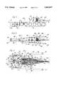
- FIG. 1is a side elevational view of a neurosurgical instrument of the present invention having a surgical instrument head and a surgical instrument handle, the surgical instrument head being fragmented with a distal end thereof not shown;
- FIG. 2is a top plan view of the neurosurgical instrument of FIG. 1;
- FIG. 3is a cross-sectional view taken along the plane of line 3--3 of FIG. 1 showing levers of the surgical instrument handle in an outward lateral position;
- FIG. 4is a cross-sectional view similar to that of FIG. 3 but showing the levers in an inward lateral position
- FIG. 5is a cross-sectional view taken along the plane of line 5--5 of FIG. 1;
- FIG. 6is a fragmented section view of a second embodiment of an instrument head of the present invention with forceps shown in a retracted position;
- FIG. 7is a cross-sectional view taken along the plane of line 7--7 of FIG. 6;
- FIG. 8is a fragmented section view similar to that of FIG. 6 but showing the forceps in an extended position
- FIG. 9is a fragmented section view of a third embodiment of an instrument head of the present invention having scissors at its distal end;
- FIG. 10is an end view showing the scissors of FIG. 9;
- FIG. 11is a cross-sectional view taken along the plane of line 11--11 of FIG. 9;
- FIG. 12is a cross-sectional view taken along the plane of line 12--12 of FIG. 9;
- FIG. 13is a cross-sectional view taken along the plane of line 13--13 of FIG. 9.
- FIG. 14is an exploded perspective view of the instrument head of FIG. 9.
- the neurosurgical instrument 20comprises a surgical instrument handle, generally indicated at 22, and a surgical instrument head, generally indicated at 24, releasably attached to the surgical instrument handle.
- the neurosurgical instrument 20comprises a surgical instrument handle, generally indicated at 22, and a surgical instrument head, generally indicated at 24, releasably attached to the surgical instrument handle.
- all of the component parts of the instrument handle 22 and instrument head 24 to be describedare constructed of materials that are capable of being sterilized, preferably alloys of titanium or aluminum to reduce the instrument's weight.
- the preferences set forth hereinare not intended to be limiting and the instrument of the invention may be constructed from a variety of materials suitable for the purposes herein described.
- the surgical instrument handle 22comprises a handle body, generally indicated at 26, a handle plunger 28, and two lever arms 30.
- the handle body 26includes a central main member (i.e., backbone 32) and a plunger housing 34 press fit into a longitudinal bore 36 in the backbone 32.
- the plunger housing 34includes a longitudinal bore 38 sized and shaped for receiving the handle plunger 28.
- the handle plunger 28is configured for reciprocating sliding motion in the bore 38 of the plunger housing 34 along an instrument axis X between a rearward position (FIG. 3) and a forward position (FIG. 4).
- the lever arms 30are elongate members having rearward ends 40 (left ends as viewed in FIGS. 1 and 2) and forward ends 42(right ends as viewed in FIGS. 1 and 2).
- the lever arms 30are fixed at their rearward ends 40 to opposite faces of the backbone 32.
- intermediate regions 44 of the lever arms 30 adjacent the rearward ends 40are of reduced thickness to permit forward portions 46 of the lever arms 30 (i.e., portions between the intermediate regions and the forward ends) to resiliently bend laterally at the intermediate regions between outward positions (FIG. 3) and inward positions (FIG. 4).
- the intermediate regions 44 of the lever arms 30are configured to act as springs to bias the forward portions 46 of the lever arms in their outward positions.
- the lateral movement of the lever arms 30is generally in a plane P which is generally perpendicular to the page of FIG. 1.
- Laterally extending pins 48extend from the backbone 32 and engage the lever arms 30 when the lever arms are in their inward positions. These pins 48 act as stops to limit inward movement of the lever arms 30.
- Protrusions 50extend upwardly from and move with the lever arms 30.
- the protrusion 50are integral with the lever arms 30 and are connected to the handle plunger 28 via links 52.
- Each link 52has a first end pin-connected at 54 to one of the protrusion 50 and a second end pin-connected at 56 to the handle plunger 28.
- the links 52extend through aligned longitudinal slots 58, 60 in the backbone 32 and plunger housing 34, respectively.
- the handle body 26further comprises a handle rotor 62 rotatably connected to the plunger housing 34 for rotation about the instrument axis X.
- the handle rotor 62has a knurled nut 64, a threaded nipple 66 protruding forward of the knurled nut 64, and two semi-circular arcuate members 68.
- the threaded nipple 66is sized and shaped for releasably receiving the instrument head 24.
- Two radially extending set screws 70are threaded through the knurled nut 64 and extend into radial bores 72 in the semi-circular arcuate members 68.
- the set screws 70compress the arcuate members 68 against each other to secure the arcuate members to the knurled nut 64.
- the two arcuate members 68are sized and configured for riding in an annular channel 74 formed between two annular flanges 76 of the plunger housing 34.
- the annular flanges 76 and arcuate members 68prevent longitudinal movement of the handle rotor 62 relative to the plunger housing 34 while facilitating free rotation of the rotor 62 relative to the plunger housing.
- the various surgical instrument heads of the present inventionare similar to the surgical instrument heads described in U.S. Pat. No. 5,370,658, incorporated herein by reference.
- the surgical instrument head 24 of this embodimentis constructed to perform a scissors cutting microsurgical operation where the cutting blades of the scissors are arranged to cut through a plane oriented at an angle relative to the instrument axis X (i.e., the longitudinal axis of the instrument handle 22).
- the instrument head 24is comprised of a head housing 78 containing the component parts of the instrument.
- the exterior of the head housing 78is generally cone shaped with the head housing tapering to a rounded point at its forward end (i.e., right hand end as viewed in the drawing figures), and the base of the housing at its rearward end (i.e., rearward end) having a cylindrical exterior surface with an exterior diameter substantially equal to the exterior diameter of the knurled nut 64 of the instrument handle 22.
- a stepped bore 80comprised of four internal cylindrical sections each having a different internal diameter is formed through the center of the head housing 78.
- a first cylindrical insert 81is press fit into the left end of the housing internal bore 80 and is held securely in a tight friction engagement in the internal bore.
- the first insert 81has a hollow internal bore 82 extending through its center with a left hand portion of the bore having an internal screw thread formed therein.
- the internal screw thread of the bore 82is determined to thread over the threaded nipple 66 of the handle rotor 62 and thereby releasably secure the instrument head 24 to the instrument handle 22 while permitting rotation of the instrument head relative to the plunger housing 34 (i.e., a stationary part of the handle).
- the first insert 81 and the head housing 78constitute static (or non-reciprocating) parts generally at the proximal end of the instrument head 24.
- a second tubular insert 86is received in the head housing internal bore 80 and is slip fit and securely held in friction engagement in the third cylindrical section of the housing internal bore.
- the second insert 86has a cylindrical interior bore and a head piston 88 is received within the bore of the second insert 86 for longitudinally reciprocating sliding movement therein.
- the head piston 88constitutes a reciprocative part of the instrument head 24.
- a longitudinal slot 92is formed through the side of the second insert 86 and a limit pin 94 secured in a side of the head piston 88 engages in the slot 92 and limits the longitudinal reciprocating movement of the head piston in the second insert.
- a coil spring 96is positioned between the right hand end face of the head piston 88 as viewed in the drawing figures and the right hand end wall of the second insert 86. The spring 96 biases the head piston 88 to the left as viewed in the drawing figures.
- a narrow hollow tube 98is press fit and securely held in the fourth cylindrical section of the head housing internal bore 80 and projects out from the tip of the instrument head 24.
- the press fit engagement of the tube 98 in the head housing 78securely holds the tube in friction engagement with the housing.
- the external diameter of the tube 98is preferably about 0.89 mm to enable the tube to be inserted into very small incisions for preforming microsurgical operations with the surgical implements formed at the distal end of the tube yet to be described.
- one scissors blade 102i.e., a non-reciprocating blade
- the bladebeing positioned to perform a scissors cutting microsurgical operation across a plane arranged at an angle relative to the instrument axis X.
- the one blade 102is secured to the half of the tube end by a brazed, butt-joint connection. The friction engagement of the tube 98 in the head housing internal bore 80 holds the scissors blade 102 stationary relative to the head housing 78 and the instrument handle 22.
- a narrow, cylindrical rod 104is received for reciprocating, longitudinal linear movement inside the internal bore of the narrow tube 98.
- the distal end of the rod 104(right end as viewed in the drawing figures) is formed in the configuration of a second scissors blade 106.
- the second scissors blade 106constitutes a moveable distal part of the instrument head 24 connected to the reciprocative part (i.e., the head plunger 88) via the rod 104.
- the rod 104is caused to move in a longitudinally linear movement relative to the narrow tube 98 the scissors blade 106 formed on the end of the rod slides adjacent the scissors blade 102 formed on the end of the tube and together they perform a scissors cutting microsurgical operation across a plane oriented at an angle relative to the longitudinal axis of the instrument handle 22.
- the rearward end of the rod 104projects from the tube 98 into the interior of the head housing 78 and extends through the end wall of the second insert 86, the coil spring 96, and through an internal bore extending longitudinally through the center of the head piston 88.
- the rearward end of the rod 104is preferably secured to the head piston 88 via suitable set screws (not shown) and is moveable therewith. Movement of the head piston 88 between a rearward position (FIG. 3) and a forward position (FIG. 4) causes the rod 104 and second scissors blade 106 to move between rearward and forward positions. When the second blade 106 is in its rearward position (FIG. 3), it is rearwardly spaced from the first blade 102. When the second blade 106 is in its forward position, it overlaps with the first blade 102 to provide the cutting operation.
- the head piston 88engages the handle plunger 28. Movement of the handle plunger 28 between its forward and rearward positions causes movement of the head piston 88 between its forward and rearward positions. As discussed above, the handle plunger 28 is moved between its forward and rearward positions by the lever arms 30, and the second scissors blade 106 is moved between its forward positions by the head piston 88. Thus, moving the lever arms 30 between their outward and inward positions causes movement of the second scissors blade 106 between its rearward and forward positions.
- a surgeongrasps the lever arms 30 and operates the lever arms in a motion similar to operation of a pair of tweezers.
- the outer surfaces of the forward portions 46 of the lever arms 30are grasped by the surgeon's thumb and index finger and the rearward portions of the lever arms rest on the dorsal side of the surgeon's hand.
- the surgeonmay move the second scissors blade 106 from its rearward position to its forward position by squeezing the lever arms 30 toward each other.
- the resiliency of the intermediate regions of the lever armscauses the lever arms to move outward. Because the spring 96 biases the head piston 88 in its rearward position, outward movement of the lever arms 30 causes rearward movement of the second scissors blade 106 to open the scissors.
- the lever arms 30are shaped and configured so that the forward ends 42 thereof extend forwardly beyond the head housing 78. These extended lever arms provide more leverage to the surgeon's hand for operating the instrument head 24 and also position the surgeon's hand closer to the operative tip (i.e., distal end) of the instrument head. This gives the surgeon a better feel and better control over movements of the instrument head tip. Because the surgeon's hand during operation of the instrument 20 is spaced approximately 1/2" below the instrument axis X, the surgeon has a clear forward line of sight generally along the instrument axis X to the distal end of the instrument head 24 as viewed from behind the handle plunger 28. Thus, during the normal and intended use of the instrument 20, the surgeon's hand does not block the line of sight.
- the handle rotor 62rotates freely relative to the plunger housing 34, the surgeon may easily rotate the instrument head 24 (including the scissors) about the instrument axis X by rotating the knurled nut with his/her other hand.
- the instrument head 24may be freely rotated about the instrument axis without the need to rotate the lever arms of the instrument handle. This enables the repositioning of the operative tip of the instrument head 24 relative to the surgical site without requiring the surgeon to move his/her hand to an awkward position.
- the scissors blades 102, 106may be replaced with a pair of opposed clamping jaws of a forceps where the jaw surfaces engage across a plane oriented at an angle relative to the longitudinal axis of the instrument handle 22.
- the operation of the forceps jawsis substantially identical to that of the scissors blades described above.
- a second embodiment of an instrument head of the present embodimentis generally indicated at 112 in FIGS. 6-8.
- This embodimenthas a microsurgical forceps formed as its surgical implement at the distal ends of the tube and rod.
- Many of the component parts of the instrument head 112 shown in FIGS. 7-9are identical to component parts of the first embodiment of the instrument head 24 and these same component parts have the same reference numerals employed in describing those parts with reference to the first embodiment of the instrument head.
- the second embodimentalso includes a head housing 78, a stepped internal bore 80 extending through the interior of the head housing and having four cylindrical sections each with different internal diameters, a first insert 81 with an internal bore 82 extending through the first insert.
- the first insert 81is held in the internal bore 80 of the head housing 78 of this second embodiment of the instrument head in substantially the same manner as the insert of the first embodiment of the instrument head.
- a second insert 86is also slip fit in the internal bore 80 of the head housing 78 of the second embodiment.
- the second insert 86has the same construction as that of the first embodiment of the instrument head.
- the second insertalso contains a coiled spring 96 in an identical manner to that of the first instrument head embodiment.
- the second instrument headdiffers from the first instrument head in the construction of the head piston 114 and the construction of the narrow tube 116 and narrow rod 118 extending from the right hand end of the head housing 78.
- the head piston 114 of the second embodiment of the instrument headis the same as that of the first embodiment in that it has a cylindrical configuration and is received for longitudinally reciprocating movement in the interior of the second insert 86.
- the head piston 114is also provided with a limit pin 94 that engages in the longitudinal slot 92 of the second insert 86 and limits the longitudinal reciprocating movement of the head piston 114 in the internal bore of the second insert.
- the coil spring 96engages against the forward end face of the head piston 114 at one end and against the end wall of the second insert 86 at its opposite end to bias the head piston to the left as viewed in the drawing figures.
- the head piston 114 of the second embodimentdiffers from the head piston of the first embodiment in that the rearward end of the hollow narrow tube 116 is secured by a press fit friction engagement in the internal bore of the head piston. With the tube 116 attached to the head piston 114 in this manner it reciprocates longitudinally along the center axis X of the instrument handle with reciprocation of the head piston along this axis.
- the second embodiment of the head piston 114further differs from the head piston of the first embodiment in that a lateral slot 122 is formed through the rearward end of the head piston. The lateral slot 122 is positioned relative to the head piston so that it aligns with the pair of diametrically opposed bore holes through the head housing 82 and through the first insert 78.
- the narrow rod 118is received in the interior of the narrow tube 116 for reciprocating longitudinally linear movement therein.
- the rearward end of the rod 118projects from the rearward end of the tube 116 into the lateral slot 122 of the head piston.
- a cylindrical pin 123 with a V-shaped notch at its distal endis inserted through aligned bore holes 183 and 185 of the head housing and first insert, respectively. The pin is held securely in friction engagement in the bore holes and the V-notch of the pin engages against one side of the rod 118 left end.
- a screw 124is screw threaded through the opposite aligned bore holes 183, 185 of the head housing and first insert, respectively, and engages against the opposite lateral side of the rod left end from the pin 123, thereby securing the rod 118 stationary relative to the head housing 82.
- the rodis longitudinally split forming a pair of forceps jaws in the rod end.
- the forceps jaws 126, 128are resiliently bent outward so that when the tube 116 is moved to the left in response to head piston 114 movement to the left, the forceps jaws project from the end of the tube and open as seen in FIG. 8.
- the right tube endcauses the forceps jaws to close.
- the handle plunger 28is retracted rearwardly (i.e., to the left) in the bore 38 in the plunger housing 34 and the coil spring 96 of the instrument head 112 biases the head piston 114 to the left as viewed in FIG. 8.
- the rearward movement of the head piston 114retracts the forward end of the narrow tube 116 from its engagement over the forward end of the rod 118 and uncovers the pair of forceps jaws 124, 126 formed in the forward (distal) end of the rod. This enables the resiliency of the forceps jaws to open the jaws as shown in FIG. 9.
- the handle plunger 28is pushed forward through the bore 38 of the plunger housing and pushes the head piston 114 to the right against the bias of the coil spring 96.
- the forward movement of the head piston 114pushes the hollow tube 116 forward over the stationary rod 118, causing the forward end of the tube 116 to pass over the open jaws formed at the forward end of the rod 118 causing the jaws to close as shown in FIG. 6 to grip an object between the jaws.
- the second embodiment of the instrument head 112is employed with the previously described instrument handle 22 to perform microsurgical forceps gripping operations employing the forceps implement formed at the right end of the rod 118.
- the forceps jaws 126, 128may be replaced by a pair of opposed scissors blades where the scissors blades slide across each other and perform a scissors cutting operation across a plane oriented parallel relative to the longitudinal axis X of the instrument handle 22.
- the operation of the scissors bladesis substantially identical to that of the forceps jaws described above.
- FIGS. 9-14show a third embodiment of the instrument head 132 of the present invention designed to be employed with the previously described instrument handle 22.
- This embodiment of the instrument head 132is used in performing microsurgical scissors cutting operations where the scissors of the instrument cut across a plane positioned parallel to the longitudinal axis of the instrument handle.
- the third embodiment of the instrument head 132is comprised of a head housing 134 having an exterior configuration substantially identical to that of the first two embodiments of the instrument heads.
- the head housingalso has an internal bore formed between the left and forward ends of the housing, the internal bore having four interconnected cylindrical sections, each of different internal diameter.
- a narrow hollow tube 138is press fit into the housing head internal bore 136 from the forward end of the housing.
- the rearward end of the tube 138is securely held in friction engagement inside the housing bore.
- the forward end of the tube 138has one blade 142 of a surgical scissors formed thereon.
- the scissors blade 142 formed at the distal end of the narrow tube 138is positioned relative to the tube to perform a surgical scissors cutting operation across a plane substantially parallel to the center axis of the instrument handle 22 and the third embodiment of the instrument head 132.
- a narrow rod 144is inserted through a center bore hole of the tube 138 and the rearward end of the rod projects from the left end of the tube into the head housing internal bore 136.
- the rodis received in the tube bore for rotational movement relative thereto but is prevented from moving in a longitudinally linear direction relative to the tube as will be explained.
- the forward end of the rod 144is formed in the configuration of a second scissors blade 146. With the rod inserted in the interior of the tube 138, the rod scissors blade 146 and the tube scissors blade 142 slide across each other in response to the rod 144 being rotated through an arc segment to perform a scissors cutting operation between the two blades. As seen in the drawing figures, the scissors cutting operation performed by the surgical implement formed at the forward ends of the rod and tube cut across a plane substantially parallel to the center longitudinal axis of the instrument handle 22 in the third embodiment of the instrument head 132.
- a first insert 148is inserted into the housing internal bore 136.
- the insert 148has a generally cylindrical configuration with a bore hole extending through its center and with an annular flange 152 formed at its forward end as viewed in the drawing figures.
- the flange 152is press fit into a cylindrical section of the housing internal bore 136 and is thereby securely held in the bore.
- the internal bore of the first insert 148is coaxial with the internal bore of the tube 138 and with the center axis of the instrument handle 22.
- the internal boreis dimensioned to receive the forward end of the narrow rod 144 therethrough enabling the rod to rotate freely within the internal bore.
- a coil spring 154is positioned over the cylindrical exterior of the insert 148 with the spring engaging against the annular flange 152 at one end.
- a cylindrical block 156is positioned adjacent the rearward end of the first insert 148.
- the blockhas a center bore that aligns coaxially with the center bore of the first insert 148 and the rearward end of the narrow rod 144 is received in the block center bore.
- a set screw 158is received in a threaded bore extending through one side of the block 156 and is tightened down in the threaded bore to securely grip the forward end of the rod 144 in the center bore of the block. With the rod 144 securely held to the block 156 by the set screw 158, as the block is rotated in the head housing interior 136, the rod 144 rotates with the block.
- a guide pin 162is inserted into and securely held by friction engagement in a second bore hole in the side of the block 156. The guide pin 162 is employed in rotating the block through an arc segment about its center longitudinal axis in a manner to be described.
- a reciprocating piston sleeve 164is positioned over the block 156 and a portion of the first insert 148.
- the forward end of the reciprocating sleeve 164engages against the left end of the coil spring 154 positioned around the first insert 148.
- the exterior surface of the sleeve 164is generally cylindrical except for a projecting guide flange 166 adjacent the forward end of the sleeve.
- the guide flangeserves to allow the sleeve to reciprocate in a longitudinally linear movement while preventing rotation of the sleeve about its center axis as will be explained.
- An angled slot 168is cut through the exterior of the sleeve to its interior bore and the guide pin 162 of the block 156 engages in the slot.
- An access hole 172is provided through the reciprocating sleeve 164 adjacent its rearward end.
- the access hole 172is provided to enable access to the set screw 158 of the block 156 to tighten or release the set screw with the block received in the internal bore of the sleeve.
- An end cap 172is secured to the rearward end of the reciprocating piston sleeve 164 and engages against the forward end face of the handle plunger 28. The engagement between the handle plunger 28 and the piston sleeve end cap 172 causes the sleeve to reciprocate longitudinally along the center axis of the handle 22 and the instrument head 132 in response to reciprocating movement of the handle plunger 28 along this axis.
- a second insert 174is press fit into the rearward end of the head housing internal bore 136.
- the second insertis comprised of two generally cylindrical sections 176, 178 with the first section 176 having a larger exterior diameter than the second section 178.
- a longitudinal slot 182is cut through the second section 178 of the insert. The slot 182 is provided to receive the guide flange 166 of the reciprocating sleeve 164.
- a bore hole 184is provided through the first section 176 of the second insert. The bore hole 184 is positioned through the insert first section so that it aligns coaxially with the bore hole through the rearward end of the reciprocating sleeve 164, providing access to the set screw of the block 156.
- the coil spring 154is compressed and the angled slot 168 of the sleeve moves relative to the guide pin 162 of the block 156.
- the movement of the angled slot 168 relative to the guide pin 162causes the block to rotate through an arc segment relative to the sleeve.
- the engagement of the forward end face of the block 156 with the rearward end face of the first insert 148prevents the block from any longitudinal movement so that the block may only rotate in the instrument head interior.
- the rod 144 secured in the internal bore of the blockalso rotates through the arc segment.
- the longitudinal, linear movement of the sleeve 164 relative to the block 156causes the angled slot 168 of the sleeve to move relative to the guide pin 162 and rotate the block back through the same arc segment.
- the rotation of the block back through the arc segmentalso rotates the rod 144 through the same arc segment and moves the scissors blade 146 formed at the right end of the rod relative to the scissors blade 142 formed at the right end of the tube to open the blades of the scissors implement.
- the surgical scissors implement formed by the blades 142, 146 at the right ends of the respective tube and rodperform a microsurgical scissors cutting operation across a plane substantially parallel to the center axis of the instrument handle 22 in the third embodiment of the instrument head 132.
- the forward ends of the tube and rodmay be modified to form forceps jaws in place of the scissors blades disclosed. Operation of this embodiment of the instrument head would then result in the microsurgical operation of clamping the forceps jaws at the forward ends of the tube and rod to grip an object positioned in a plane substantially parallel to the center longitudinal axis of the instrument handle and instrument head.
Landscapes
- Health & Medical Sciences (AREA)
- Surgery (AREA)
- Life Sciences & Earth Sciences (AREA)
- Biomedical Technology (AREA)
- Nuclear Medicine, Radiotherapy & Molecular Imaging (AREA)
- Engineering & Computer Science (AREA)
- Ophthalmology & Optometry (AREA)
- Heart & Thoracic Surgery (AREA)
- Medical Informatics (AREA)
- Molecular Biology (AREA)
- Animal Behavior & Ethology (AREA)
- General Health & Medical Sciences (AREA)
- Public Health (AREA)
- Veterinary Medicine (AREA)
- Surgical Instruments (AREA)
Abstract
Description
Claims (20)
Priority Applications (1)
| Application Number | Priority Date | Filing Date | Title |
|---|---|---|---|
| US08/920,349US5893877A (en) | 1996-04-10 | 1997-07-16 | Surgical instrument with offset handle |
Applications Claiming Priority (2)
| Application Number | Priority Date | Filing Date | Title |
|---|---|---|---|
| US63061396A | 1996-04-10 | 1996-04-10 | |
| US08/920,349US5893877A (en) | 1996-04-10 | 1997-07-16 | Surgical instrument with offset handle |
Related Parent Applications (1)
| Application Number | Title | Priority Date | Filing Date |
|---|---|---|---|
| US63061396AContinuation | 1996-04-10 | 1996-04-10 |
Publications (1)
| Publication Number | Publication Date |
|---|---|
| US5893877Atrue US5893877A (en) | 1999-04-13 |
Family
ID=24527879
Family Applications (1)
| Application Number | Title | Priority Date | Filing Date |
|---|---|---|---|
| US08/920,349Expired - LifetimeUS5893877A (en) | 1996-04-10 | 1997-07-16 | Surgical instrument with offset handle |
Country Status (1)
| Country | Link |
|---|---|
| US (1) | US5893877A (en) |
Cited By (171)
| Publication number | Priority date | Publication date | Assignee | Title |
|---|---|---|---|---|
| EP1201193A1 (en) | 2000-10-19 | 2002-05-02 | Alcon Grieshaber AG | Surgical instrument |
| WO2002080783A1 (en)* | 2001-04-06 | 2002-10-17 | Sherwood Services Ag | Vessel sealer and divider |
| US20030018332A1 (en)* | 2001-06-20 | 2003-01-23 | Schmaltz Dale Francis | Bipolar electrosurgical instrument with replaceable electrodes |
| US20030074766A1 (en)* | 2001-10-24 | 2003-04-24 | Tillim Stephen L. | Handle/grip and method for designing the like |
| US6575989B1 (en) | 1999-09-13 | 2003-06-10 | Synergetics, Inc. | Adjustable stiffness membrane scraper |
| US20030109875A1 (en)* | 1999-10-22 | 2003-06-12 | Tetzlaff Philip M. | Open vessel sealing forceps with disposable electrodes |
| US20030199869A1 (en)* | 1998-10-23 | 2003-10-23 | Johnson Kristin D. | Vessel sealing instrument |
| US20030229344A1 (en)* | 2002-01-22 | 2003-12-11 | Dycus Sean T. | Vessel sealer and divider and method of manufacturing same |
| US20040078935A1 (en)* | 2001-10-24 | 2004-04-29 | Tillim Stephen L. | Handle and forceps/tweezers and method and apparatus for designing the like |
| WO2004037312A2 (en) | 2002-10-24 | 2004-05-06 | Tillim Stephen L | Handle for forceps/tweezers and method and apparatus for designing the like |
| US20040087943A1 (en)* | 2001-04-06 | 2004-05-06 | Dycus Sean T. | Vessel sealer an divider |
| US20040088827A1 (en)* | 2001-10-24 | 2004-05-13 | Tillim Stephen L. | Parallel handle system and method for designing a parallel handle system |
| US20040116924A1 (en)* | 2001-04-06 | 2004-06-17 | Dycus Sean T. | Vessel sealer and divider |
| US20040176762A1 (en)* | 1997-11-12 | 2004-09-09 | Lawes Kate R. | Electrosurgical instrument reducing flashover |
| US20040193153A1 (en)* | 2001-04-06 | 2004-09-30 | Sartor Joe Don | Molded insulating hinge for bipolar instruments |
| US20040199205A1 (en)* | 2002-10-24 | 2004-10-07 | Tillim Stephen L. | Handle for forceps/tweezers and method and apparatus for designing the like |
| US20040225288A1 (en)* | 1997-11-12 | 2004-11-11 | Buysse Steven Paul | Bipolar electrosurgical instrument for sealing vessels |
| US20040236325A1 (en)* | 2001-04-06 | 2004-11-25 | Tetzlaff Philip M. | Vesel sealing forceps with disposable electrodes |
| US20040243125A1 (en)* | 2001-04-06 | 2004-12-02 | Sean Dycus | Vessel sealer and divider |
| US20040254573A1 (en)* | 2003-06-13 | 2004-12-16 | Dycus Sean T. | Vessel sealer and divider for use with small trocars and cannulas |
| US20040250419A1 (en)* | 2003-06-13 | 2004-12-16 | Sremcich Paul S. | Method of manufacturing jaw assembly for vessel sealer and divider |
| US20050004568A1 (en)* | 1997-11-12 | 2005-01-06 | Lawes Kate R. | Electrosurgical instrument reducing thermal spread |
| US20050004570A1 (en)* | 2003-05-01 | 2005-01-06 | Chapman Troy J. | Electrosurgical instrument which reduces thermal damage to adjacent tissue |
| US20050107785A1 (en)* | 2003-06-13 | 2005-05-19 | Dycus Sean T. | Vessel sealer and divider having elongated knife stroke and safety for cutting mechanism |
| US20050113826A1 (en)* | 2002-10-04 | 2005-05-26 | Johnson Kristin D. | Vessel sealing instrument with electrical cutting mechanism |
| US20050113828A1 (en)* | 2003-11-20 | 2005-05-26 | Chelsea Shields | Electrically conductive/insulative over-shoe for tissue fusion |
| US20050119655A1 (en)* | 2003-11-19 | 2005-06-02 | Moses Michael C. | Open vessel sealing instrument with cutting mechanism |
| US20050137592A1 (en)* | 1998-10-23 | 2005-06-23 | Nguyen Lap P. | Vessel sealing instrument |
| US20050137590A1 (en)* | 2003-11-17 | 2005-06-23 | Kate Lawes | Bipolar forceps having monopolar extension |
| US20050154387A1 (en)* | 2003-11-19 | 2005-07-14 | Moses Michael C. | Open vessel sealing instrument with hourglass cutting mechanism and over-ratchet safety |
| US20060052777A1 (en)* | 2004-09-09 | 2006-03-09 | Dumbauld Patrick L | Forceps with spring loaded end effector assembly |
| US20060064085A1 (en)* | 2004-09-21 | 2006-03-23 | Schechter David A | Articulating bipolar electrosurgical instrument |
| US20060079933A1 (en)* | 2004-10-08 | 2006-04-13 | Dylan Hushka | Latching mechanism for forceps |
| US20060137144A1 (en)* | 2001-10-24 | 2006-06-29 | Tillim Stephen L | Handle/grip and method for designing the like |
| US20060167450A1 (en)* | 2005-01-14 | 2006-07-27 | Johnson Kristin D | Vessel sealer and divider with rotating sealer and cutter |
| US20060173452A1 (en)* | 2002-06-06 | 2006-08-03 | Buysse Steven P | Laparoscopic bipolar electrosurgical instrument |
| US20060190035A1 (en)* | 2004-10-08 | 2006-08-24 | Sherwood Services Ag | Latching mechanism for forceps |
| US20060189981A1 (en)* | 2001-04-06 | 2006-08-24 | Dycus Sean T | Vessel sealer and divider |
| USD535027S1 (en) | 2004-10-06 | 2007-01-09 | Sherwood Services Ag | Low profile vessel sealing and cutting mechanism |
| US7160299B2 (en) | 2003-05-01 | 2007-01-09 | Sherwood Services Ag | Method of fusing biomaterials with radiofrequency energy |
| US20070043352A1 (en)* | 2005-08-19 | 2007-02-22 | Garrison David M | Single action tissue sealer |
| US20070074807A1 (en)* | 2005-09-30 | 2007-04-05 | Sherwood Services Ag | Method for manufacturing an end effector assembly |
| USD541418S1 (en) | 2004-10-06 | 2007-04-24 | Sherwood Services Ag | Lung sealing device |
| USD541938S1 (en) | 2004-04-09 | 2007-05-01 | Sherwood Services Ag | Open vessel sealer with mechanical cutter |
| US20070118111A1 (en)* | 2005-11-22 | 2007-05-24 | Sherwood Services Ag | Electrosurgical forceps with energy based tissue division |
| US7223265B2 (en) | 2002-12-10 | 2007-05-29 | Sherwood Services Ag | Electrosurgical electrode having a non-conductive porous ceramic coating |
| US7232440B2 (en) | 2003-11-17 | 2007-06-19 | Sherwood Services Ag | Bipolar forceps having monopolar extension |
| US7241296B2 (en) | 1997-11-12 | 2007-07-10 | Sherwood Services Ag | Bipolar electrosurgical instrument for sealing vessels |
| US20070173811A1 (en)* | 2006-01-24 | 2007-07-26 | Sherwood Services Ag | Method and system for controlling delivery of energy to divide tissue |
| US20070179499A1 (en)* | 2003-06-13 | 2007-08-02 | Garrison David M | Vessel sealer and divider for use with small trocars and cannulas |
| US7252667B2 (en) | 2003-11-19 | 2007-08-07 | Sherwood Services Ag | Open vessel sealing instrument with cutting mechanism and distal lockout |
| US7255697B2 (en) | 2001-04-06 | 2007-08-14 | Sherwood Services Ag | Vessel sealer and divider |
| US7270664B2 (en) | 2002-10-04 | 2007-09-18 | Sherwood Services Ag | Vessel sealing instrument with electrical cutting mechanism |
| US20070260238A1 (en)* | 2006-05-05 | 2007-11-08 | Sherwood Services Ag | Combined energy level button |
| US20080033428A1 (en)* | 2006-08-04 | 2008-02-07 | Sherwood Services Ag | System and method for disabling handswitching on an electrosurgical instrument |
| USD564662S1 (en) | 2004-10-13 | 2008-03-18 | Sherwood Services Ag | Hourglass-shaped knife for electrosurgical forceps |
| USD567943S1 (en) | 2004-10-08 | 2008-04-29 | Sherwood Services Ag | Over-ratchet safety for a vessel sealing instrument |
| US7377920B2 (en) | 1997-11-14 | 2008-05-27 | Sherwood Services Ag | Laparoscopic bipolar electrosurgical instrument |
| US7384421B2 (en) | 2004-10-06 | 2008-06-10 | Sherwood Services Ag | Slide-activated cutting assembly |
| US7384420B2 (en) | 2001-04-06 | 2008-06-10 | Sherwood Services Ag | Vessel sealer and divider |
| USD575395S1 (en) | 2007-02-15 | 2008-08-19 | Tyco Healthcare Group Lp | Hemostat style elongated dissecting and dividing instrument |
| USD575401S1 (en) | 2007-06-12 | 2008-08-19 | Tyco Healthcare Group Lp | Vessel sealer |
| US7435249B2 (en) | 1997-11-12 | 2008-10-14 | Covidien Ag | Electrosurgical instruments which reduces collateral damage to adjacent tissue |
| US7473253B2 (en) | 2001-04-06 | 2009-01-06 | Covidien Ag | Vessel sealer and divider with non-conductive stop members |
| US7491202B2 (en) | 2005-03-31 | 2009-02-17 | Covidien Ag | Electrosurgical forceps with slow closure sealing plates and method of sealing tissue |
| US7491201B2 (en) | 2003-05-15 | 2009-02-17 | Covidien Ag | Tissue sealer with non-conductive variable stop members and method of sealing tissue |
| DE102007040290A1 (en)* | 2007-08-24 | 2009-02-26 | Geuder Ag | Surgical instrument used in ophthalmology, has detachable and rotatable head carrying tool and operated by mechanism in handle |
| US7500975B2 (en) | 2003-11-19 | 2009-03-10 | Covidien Ag | Spring loaded reciprocating tissue cutting mechanism in a forceps-style electrosurgical instrument |
| US7553312B2 (en) | 1998-10-23 | 2009-06-30 | Covidien Ag | Vessel sealing instrument |
| US7582087B2 (en) | 1998-10-23 | 2009-09-01 | Covidien Ag | Vessel sealing instrument |
| USD605288S1 (en) | 2009-04-10 | 2009-12-01 | Edwards Lifesciences Corporation | Handle for a medical device |
| US7628792B2 (en) | 2004-10-08 | 2009-12-08 | Covidien Ag | Bilateral foot jaws |
| US7641653B2 (en) | 2006-05-04 | 2010-01-05 | Covidien Ag | Open vessel sealing forceps disposable handswitch |
| US20100004677A1 (en)* | 2008-07-03 | 2010-01-07 | Edwards Lifesciences Corporation | Shafted surgical instruments for remote access surgical procedures |
| US7686827B2 (en) | 2004-10-21 | 2010-03-30 | Covidien Ag | Magnetic closure mechanism for hemostat |
| US7722607B2 (en) | 2005-09-30 | 2010-05-25 | Covidien Ag | In-line vessel sealer and divider |
| US7744615B2 (en) | 2006-07-18 | 2010-06-29 | Covidien Ag | Apparatus and method for transecting tissue on a bipolar vessel sealing instrument |
| US7766910B2 (en) | 2006-01-24 | 2010-08-03 | Tyco Healthcare Group Lp | Vessel sealer and divider for large tissue structures |
| US7776036B2 (en) | 2003-03-13 | 2010-08-17 | Covidien Ag | Bipolar concentric electrode assembly for soft tissue fusion |
| US7776037B2 (en) | 2006-07-07 | 2010-08-17 | Covidien Ag | System and method for controlling electrode gap during tissue sealing |
| US7789878B2 (en) | 2005-09-30 | 2010-09-07 | Covidien Ag | In-line vessel sealer and divider |
| US7799026B2 (en) | 2002-11-14 | 2010-09-21 | Covidien Ag | Compressible jaw configuration with bipolar RF output electrodes for soft tissue fusion |
| US7819872B2 (en) | 2005-09-30 | 2010-10-26 | Covidien Ag | Flexible endoscopic catheter with ligasure |
| US7828798B2 (en) | 1997-11-14 | 2010-11-09 | Covidien Ag | Laparoscopic bipolar electrosurgical instrument |
| US7837685B2 (en) | 2005-07-13 | 2010-11-23 | Covidien Ag | Switch mechanisms for safe activation of energy on an electrosurgical instrument |
| US7846158B2 (en) | 2006-05-05 | 2010-12-07 | Covidien Ag | Apparatus and method for electrode thermosurgery |
| US7846161B2 (en) | 2005-09-30 | 2010-12-07 | Covidien Ag | Insulating boot for electrosurgical forceps |
| US7857812B2 (en) | 2003-06-13 | 2010-12-28 | Covidien Ag | Vessel sealer and divider having elongated knife stroke and safety for cutting mechanism |
| US7877853B2 (en) | 2007-09-20 | 2011-02-01 | Tyco Healthcare Group Lp | Method of manufacturing end effector assembly for sealing tissue |
| US7877852B2 (en) | 2007-09-20 | 2011-02-01 | Tyco Healthcare Group Lp | Method of manufacturing an end effector assembly for sealing tissue |
| US7879035B2 (en) | 2005-09-30 | 2011-02-01 | Covidien Ag | Insulating boot for electrosurgical forceps |
| US7887535B2 (en) | 1999-10-18 | 2011-02-15 | Covidien Ag | Vessel sealing wave jaw |
| US7909823B2 (en) | 2005-01-14 | 2011-03-22 | Covidien Ag | Open vessel sealing instrument |
| US7931649B2 (en) | 2002-10-04 | 2011-04-26 | Tyco Healthcare Group Lp | Vessel sealing instrument with electrical cutting mechanism |
| US7951149B2 (en) | 2006-10-17 | 2011-05-31 | Tyco Healthcare Group Lp | Ablative material for use with tissue treatment device |
| US7955332B2 (en) | 2004-10-08 | 2011-06-07 | Covidien Ag | Mechanism for dividing tissue in a hemostat-style instrument |
| US8016827B2 (en) | 2008-10-09 | 2011-09-13 | Tyco Healthcare Group Lp | Apparatus, system, and method for performing an electrosurgical procedure |
| USD649249S1 (en) | 2007-02-15 | 2011-11-22 | Tyco Healthcare Group Lp | End effectors of an elongated dissecting and dividing instrument |
| US8070746B2 (en) | 2006-10-03 | 2011-12-06 | Tyco Healthcare Group Lp | Radiofrequency fusion of cardiac tissue |
| US8128624B2 (en) | 2003-05-01 | 2012-03-06 | Covidien Ag | Electrosurgical instrument that directs energy delivery and protects adjacent tissue |
| US8142473B2 (en) | 2008-10-03 | 2012-03-27 | Tyco Healthcare Group Lp | Method of transferring rotational motion in an articulating surgical instrument |
| US8162973B2 (en) | 2008-08-15 | 2012-04-24 | Tyco Healthcare Group Lp | Method of transferring pressure in an articulating surgical instrument |
| US8197479B2 (en) | 2008-12-10 | 2012-06-12 | Tyco Healthcare Group Lp | Vessel sealer and divider |
| US8211105B2 (en) | 1997-11-12 | 2012-07-03 | Covidien Ag | Electrosurgical instrument which reduces collateral damage to adjacent tissue |
| US8221416B2 (en) | 2007-09-28 | 2012-07-17 | Tyco Healthcare Group Lp | Insulating boot for electrosurgical forceps with thermoplastic clevis |
| US8235992B2 (en) | 2007-09-28 | 2012-08-07 | Tyco Healthcare Group Lp | Insulating boot with mechanical reinforcement for electrosurgical forceps |
| US8235993B2 (en) | 2007-09-28 | 2012-08-07 | Tyco Healthcare Group Lp | Insulating boot for electrosurgical forceps with exohinged structure |
| US8236025B2 (en) | 2007-09-28 | 2012-08-07 | Tyco Healthcare Group Lp | Silicone insulated electrosurgical forceps |
| US8241282B2 (en) | 2006-01-24 | 2012-08-14 | Tyco Healthcare Group Lp | Vessel sealing cutting assemblies |
| US8241283B2 (en) | 2007-09-28 | 2012-08-14 | Tyco Healthcare Group Lp | Dual durometer insulating boot for electrosurgical forceps |
| US8251996B2 (en) | 2007-09-28 | 2012-08-28 | Tyco Healthcare Group Lp | Insulating sheath for electrosurgical forceps |
| US8257387B2 (en) | 2008-08-15 | 2012-09-04 | Tyco Healthcare Group Lp | Method of transferring pressure in an articulating surgical instrument |
| US8267935B2 (en) | 2007-04-04 | 2012-09-18 | Tyco Healthcare Group Lp | Electrosurgical instrument reducing current densities at an insulator conductor junction |
| US8267936B2 (en) | 2007-09-28 | 2012-09-18 | Tyco Healthcare Group Lp | Insulating mechanically-interfaced adhesive for electrosurgical forceps |
| US8298232B2 (en) | 2006-01-24 | 2012-10-30 | Tyco Healthcare Group Lp | Endoscopic vessel sealer and divider for large tissue structures |
| US8303582B2 (en) | 2008-09-15 | 2012-11-06 | Tyco Healthcare Group Lp | Electrosurgical instrument having a coated electrode utilizing an atomic layer deposition technique |
| US8317787B2 (en) | 2008-08-28 | 2012-11-27 | Covidien Lp | Tissue fusion jaw angle improvement |
| US8348948B2 (en) | 2004-03-02 | 2013-01-08 | Covidien Ag | Vessel sealing system using capacitive RF dielectric heating |
| USD680220S1 (en) | 2012-01-12 | 2013-04-16 | Coviden IP | Slider handle for laparoscopic device |
| US8454602B2 (en) | 2009-05-07 | 2013-06-04 | Covidien Lp | Apparatus, system, and method for performing an electrosurgical procedure |
| US8469956B2 (en) | 2008-07-21 | 2013-06-25 | Covidien Lp | Variable resistor jaw |
| US8469957B2 (en) | 2008-10-07 | 2013-06-25 | Covidien Lp | Apparatus, system, and method for performing an electrosurgical procedure |
| US8486107B2 (en) | 2008-10-20 | 2013-07-16 | Covidien Lp | Method of sealing tissue using radiofrequency energy |
| US20130204283A1 (en)* | 2004-08-10 | 2013-08-08 | Asico Llc | Nucleus Chopper and Splitter |
| US20130211414A1 (en)* | 2004-08-10 | 2013-08-15 | Asico Llc | Nucleus Chopper and Splitter |
| US8523898B2 (en) | 2009-07-08 | 2013-09-03 | Covidien Lp | Endoscopic electrosurgical jaws with offset knife |
| US8535312B2 (en) | 2008-09-25 | 2013-09-17 | Covidien Lp | Apparatus, system and method for performing an electrosurgical procedure |
| US8591506B2 (en) | 1998-10-23 | 2013-11-26 | Covidien Ag | Vessel sealing system |
| US8597297B2 (en) | 2006-08-29 | 2013-12-03 | Covidien Ag | Vessel sealing instrument with multiple electrode configurations |
| US8623276B2 (en) | 2008-02-15 | 2014-01-07 | Covidien Lp | Method and system for sterilizing an electrosurgical instrument |
| US8636761B2 (en) | 2008-10-09 | 2014-01-28 | Covidien Lp | Apparatus, system, and method for performing an endoscopic electrosurgical procedure |
| US20140121697A1 (en)* | 2012-10-30 | 2014-05-01 | Katalyst Surgical, Llc | Atraumatic microsurgical forceps |
| US20140135820A1 (en)* | 2012-11-13 | 2014-05-15 | Alcon Research, Ltd. | Disposable capsulorhexis forceps |
| US8734443B2 (en) | 2006-01-24 | 2014-05-27 | Covidien Lp | Vessel sealer and divider for large tissue structures |
| US8764748B2 (en) | 2008-02-06 | 2014-07-01 | Covidien Lp | End effector assembly for electrosurgical device and method for making the same |
| US8784417B2 (en) | 2008-08-28 | 2014-07-22 | Covidien Lp | Tissue fusion jaw angle improvement |
| US8795274B2 (en) | 2008-08-28 | 2014-08-05 | Covidien Lp | Tissue fusion jaw angle improvement |
| US8852228B2 (en) | 2009-01-13 | 2014-10-07 | Covidien Lp | Apparatus, system, and method for performing an electrosurgical procedure |
| US8898888B2 (en) | 2009-09-28 | 2014-12-02 | Covidien Lp | System for manufacturing electrosurgical seal plates |
| US8968314B2 (en) | 2008-09-25 | 2015-03-03 | Covidien Lp | Apparatus, system and method for performing an electrosurgical procedure |
| US9023043B2 (en) | 2007-09-28 | 2015-05-05 | Covidien Lp | Insulating mechanically-interfaced boot and jaws for electrosurgical forceps |
| US9028493B2 (en) | 2009-09-18 | 2015-05-12 | Covidien Lp | In vivo attachable and detachable end effector assembly and laparoscopic surgical instrument and methods therefor |
| US9113940B2 (en) | 2011-01-14 | 2015-08-25 | Covidien Lp | Trigger lockout and kickback mechanism for surgical instruments |
| CN104970918A (en)* | 2015-07-27 | 2015-10-14 | 浙江大学 | Microforceps used for posterior curvilinear capsulorhexis of sclera microincision posterior cataract |
| US9375254B2 (en) | 2008-09-25 | 2016-06-28 | Covidien Lp | Seal and separate algorithm |
| US9603652B2 (en) | 2008-08-21 | 2017-03-28 | Covidien Lp | Electrosurgical instrument including a sensor |
| US9782189B2 (en) | 2010-09-24 | 2017-10-10 | Katalyst Surgical, Llc | Microsurgical handle and instrument |
| US9827141B2 (en) | 2013-06-21 | 2017-11-28 | Novartis Ag | Systems and techniques for tissue manipulation during ocular surgery |
| US9848938B2 (en) | 2003-11-13 | 2017-12-26 | Covidien Ag | Compressible jaw configuration with bipolar RF output electrodes for soft tissue fusion |
| EP3266393A1 (en)* | 2016-07-08 | 2018-01-10 | Peter Tschida | Surgical instrument |
| WO2018017296A1 (en)* | 2016-07-17 | 2018-01-25 | Katalyst Surgical, Llc | Single-use instrument tip for customized reusable handles |
| US9987078B2 (en) | 2015-07-22 | 2018-06-05 | Covidien Lp | Surgical forceps |
| US10213250B2 (en) | 2015-11-05 | 2019-02-26 | Covidien Lp | Deployment and safety mechanisms for surgical instruments |
| US10231777B2 (en) | 2014-08-26 | 2019-03-19 | Covidien Lp | Methods of manufacturing jaw members of an end-effector assembly for a surgical instrument |
| US10391232B2 (en) | 2014-10-10 | 2019-08-27 | Katalyst Surgical, Llc | Cannula ingress system |
| US10413445B2 (en) | 2012-11-07 | 2019-09-17 | Katalyst Surgical, Llc | Atraumatic microsurgical forceps |
| US10478165B2 (en) | 2011-10-03 | 2019-11-19 | Katalyst Surgical, Llc | Multi-utility surgical instrument |
| US10631918B2 (en) | 2015-08-14 | 2020-04-28 | Covidien Lp | Energizable surgical attachment for a mechanical clamp |
| US10646267B2 (en) | 2013-08-07 | 2020-05-12 | Covidien LLP | Surgical forceps |
| US10695043B2 (en) | 2017-02-21 | 2020-06-30 | Katalyst Surgical, Llc | Surgical instrument subcomponent integration by additive manufacturing |
| US10828191B2 (en) | 2014-04-21 | 2020-11-10 | Katalyst Surgical, Llc | Microsurgical instrument tip |
| US10828192B2 (en) | 2012-01-26 | 2020-11-10 | Katalyst Surgical, Llc | Surgical instrument sleeve |
| US10835309B1 (en) | 2002-06-25 | 2020-11-17 | Covidien Ag | Vessel sealer and divider |
| US10849640B2 (en) | 2018-05-23 | 2020-12-01 | Katalyst Surgical, Llc | Membrane aggregating forceps |
| US10856933B2 (en) | 2016-08-02 | 2020-12-08 | Covidien Lp | Surgical instrument housing incorporating a channel and methods of manufacturing the same |
| US10918407B2 (en) | 2016-11-08 | 2021-02-16 | Covidien Lp | Surgical instrument for grasping, treating, and/or dividing tissue |
| US10987159B2 (en) | 2015-08-26 | 2021-04-27 | Covidien Lp | Electrosurgical end effector assemblies and electrosurgical forceps configured to reduce thermal spread |
| US11160935B2 (en) | 2016-06-16 | 2021-11-02 | Katalyst Surgical, Llc | Reusable instrument handle with single-use tip |
| US11166759B2 (en) | 2017-05-16 | 2021-11-09 | Covidien Lp | Surgical forceps |
| USD956973S1 (en) | 2003-06-13 | 2022-07-05 | Covidien Ag | Movable handle for endoscopic vessel sealer and divider |
| US12127755B2 (en) | 2013-03-12 | 2024-10-29 | Katalyst Surgical, Llc | Membrane removing instrument |
Citations (21)
| Publication number | Priority date | Publication date | Assignee | Title |
|---|---|---|---|---|
| US2165374A (en)* | 1938-10-14 | 1939-07-11 | William L Heilig | Tweezers |
| FR1026461A (en)* | 1950-10-24 | 1953-04-28 | Mechanical tweezers | |
| US2898915A (en)* | 1955-04-14 | 1959-08-11 | Kammer Karl | Implement for tying blood vessels |
| US4165745A (en)* | 1977-05-06 | 1979-08-28 | Heifetz Milton D | Surgical manipulator |
| US4258716A (en)* | 1978-02-06 | 1981-03-31 | The University Of Melbourne | Microsurgical instruments |
| WO1982000968A1 (en)* | 1980-09-18 | 1982-04-01 | Dippert M | Surgical stapler drive mechanism |
| GB2091624A (en)* | 1981-01-22 | 1982-08-04 | Univ Duke | Forceps |
| US4433687A (en)* | 1980-05-02 | 1984-02-28 | Acufex Microsurgical, Inc. | Microsurgical scissors |
| US4598711A (en)* | 1984-08-09 | 1986-07-08 | American Cyanamid Company | Surgical instrument |
| US4602631A (en)* | 1983-09-08 | 1986-07-29 | Noboru Funatsu | Forceps for clamping surgical clips |
| US4644651A (en)* | 1984-03-19 | 1987-02-24 | Jacobsen Research Corp. | Instrument for gripping or cutting |
| US4760848A (en)* | 1986-11-03 | 1988-08-02 | Hasson Harrith M | Rotational surgical instrument |
| US4873979A (en)* | 1986-03-18 | 1989-10-17 | Khalil Hanna | Micro-surgical instrument for use as gripper of scissors |
| US4938214A (en)* | 1984-09-10 | 1990-07-03 | Micrins Surgical Instruments, Ltd. | Hand held surgical tool |
| US4955887A (en)* | 1988-05-11 | 1990-09-11 | Storz Instrument Company | Optical surgical instrument |
| US4995876A (en)* | 1985-03-27 | 1991-02-26 | Puig Ana E | Neurosurgical clip applier |
| US4997436A (en)* | 1988-06-03 | 1991-03-05 | Oberlander Michael A | Arthroscopic clip insertion tool |
| US5122150A (en)* | 1985-03-27 | 1992-06-16 | Puig Ana E | Neurosurgical clip applier |
| US5141514A (en)* | 1990-05-18 | 1992-08-25 | Allflex New Zealand Ltd. | Ear tag applicator |
| US5184625A (en)* | 1992-04-16 | 1993-02-09 | Cordis Corporation | Biopsy forceps device having improved handle |
| US5370658A (en)* | 1992-11-05 | 1994-12-06 | Synergetics, Inc. | Microsurgical instrument having dexterous handle with interchangeable instrument heads |
- 1997
- 1997-07-16USUS08/920,349patent/US5893877A/ennot_activeExpired - Lifetime
Patent Citations (21)
| Publication number | Priority date | Publication date | Assignee | Title |
|---|---|---|---|---|
| US2165374A (en)* | 1938-10-14 | 1939-07-11 | William L Heilig | Tweezers |
| FR1026461A (en)* | 1950-10-24 | 1953-04-28 | Mechanical tweezers | |
| US2898915A (en)* | 1955-04-14 | 1959-08-11 | Kammer Karl | Implement for tying blood vessels |
| US4165745A (en)* | 1977-05-06 | 1979-08-28 | Heifetz Milton D | Surgical manipulator |
| US4258716A (en)* | 1978-02-06 | 1981-03-31 | The University Of Melbourne | Microsurgical instruments |
| US4433687A (en)* | 1980-05-02 | 1984-02-28 | Acufex Microsurgical, Inc. | Microsurgical scissors |
| WO1982000968A1 (en)* | 1980-09-18 | 1982-04-01 | Dippert M | Surgical stapler drive mechanism |
| GB2091624A (en)* | 1981-01-22 | 1982-08-04 | Univ Duke | Forceps |
| US4602631A (en)* | 1983-09-08 | 1986-07-29 | Noboru Funatsu | Forceps for clamping surgical clips |
| US4644651A (en)* | 1984-03-19 | 1987-02-24 | Jacobsen Research Corp. | Instrument for gripping or cutting |
| US4598711A (en)* | 1984-08-09 | 1986-07-08 | American Cyanamid Company | Surgical instrument |
| US4938214A (en)* | 1984-09-10 | 1990-07-03 | Micrins Surgical Instruments, Ltd. | Hand held surgical tool |
| US4995876A (en)* | 1985-03-27 | 1991-02-26 | Puig Ana E | Neurosurgical clip applier |
| US5122150A (en)* | 1985-03-27 | 1992-06-16 | Puig Ana E | Neurosurgical clip applier |
| US4873979A (en)* | 1986-03-18 | 1989-10-17 | Khalil Hanna | Micro-surgical instrument for use as gripper of scissors |
| US4760848A (en)* | 1986-11-03 | 1988-08-02 | Hasson Harrith M | Rotational surgical instrument |
| US4955887A (en)* | 1988-05-11 | 1990-09-11 | Storz Instrument Company | Optical surgical instrument |
| US4997436A (en)* | 1988-06-03 | 1991-03-05 | Oberlander Michael A | Arthroscopic clip insertion tool |
| US5141514A (en)* | 1990-05-18 | 1992-08-25 | Allflex New Zealand Ltd. | Ear tag applicator |
| US5184625A (en)* | 1992-04-16 | 1993-02-09 | Cordis Corporation | Biopsy forceps device having improved handle |
| US5370658A (en)* | 1992-11-05 | 1994-12-06 | Synergetics, Inc. | Microsurgical instrument having dexterous handle with interchangeable instrument heads |
Cited By (316)
| Publication number | Priority date | Publication date | Assignee | Title |
|---|---|---|---|---|
| US8298228B2 (en) | 1997-11-12 | 2012-10-30 | Coviden Ag | Electrosurgical instrument which reduces collateral damage to adjacent tissue |
| US7135020B2 (en) | 1997-11-12 | 2006-11-14 | Sherwood Services Ag | Electrosurgical instrument reducing flashover |
| US8211105B2 (en) | 1997-11-12 | 2012-07-03 | Covidien Ag | Electrosurgical instrument which reduces collateral damage to adjacent tissue |
| US7160298B2 (en) | 1997-11-12 | 2007-01-09 | Sherwood Services Ag | Electrosurgical instrument which reduces effects to adjacent tissue structures |
| US7179258B2 (en) | 1997-11-12 | 2007-02-20 | Sherwood Services Ag | Bipolar electrosurgical instrument for sealing vessels |
| US7241296B2 (en) | 1997-11-12 | 2007-07-10 | Sherwood Services Ag | Bipolar electrosurgical instrument for sealing vessels |
| US7435249B2 (en) | 1997-11-12 | 2008-10-14 | Covidien Ag | Electrosurgical instruments which reduces collateral damage to adjacent tissue |
| US7963965B2 (en) | 1997-11-12 | 2011-06-21 | Covidien Ag | Bipolar electrosurgical instrument for sealing vessels |
| US20040176762A1 (en)* | 1997-11-12 | 2004-09-09 | Lawes Kate R. | Electrosurgical instrument reducing flashover |
| US20050004568A1 (en)* | 1997-11-12 | 2005-01-06 | Lawes Kate R. | Electrosurgical instrument reducing thermal spread |
| US20040225288A1 (en)* | 1997-11-12 | 2004-11-11 | Buysse Steven Paul | Bipolar electrosurgical instrument for sealing vessels |
| US7377920B2 (en) | 1997-11-14 | 2008-05-27 | Sherwood Services Ag | Laparoscopic bipolar electrosurgical instrument |
| US7828798B2 (en) | 1997-11-14 | 2010-11-09 | Covidien Ag | Laparoscopic bipolar electrosurgical instrument |
| US7947041B2 (en) | 1998-10-23 | 2011-05-24 | Covidien Ag | Vessel sealing instrument |
| US7510556B2 (en) | 1998-10-23 | 2009-03-31 | Coviden Ag | Vessel sealing instrument |
| US9375271B2 (en) | 1998-10-23 | 2016-06-28 | Covidien Ag | Vessel sealing system |
| US7887536B2 (en) | 1998-10-23 | 2011-02-15 | Covidien Ag | Vessel sealing instrument |
| US9375270B2 (en) | 1998-10-23 | 2016-06-28 | Covidien Ag | Vessel sealing system |
| US20060189980A1 (en)* | 1998-10-23 | 2006-08-24 | Johnson Kristin D | Vessel sealing instrument |
| US9463067B2 (en) | 1998-10-23 | 2016-10-11 | Covidien Ag | Vessel sealing system |
| US7582087B2 (en) | 1998-10-23 | 2009-09-01 | Covidien Ag | Vessel sealing instrument |
| US7896878B2 (en) | 1998-10-23 | 2011-03-01 | Coviden Ag | Vessel sealing instrument |
| US7553312B2 (en) | 1998-10-23 | 2009-06-30 | Covidien Ag | Vessel sealing instrument |
| US7513898B2 (en) | 1998-10-23 | 2009-04-07 | Covidien Ag | Vessel sealing instrument |
| US9107672B2 (en) | 1998-10-23 | 2015-08-18 | Covidien Ag | Vessel sealing forceps with disposable electrodes |
| US7267677B2 (en) | 1998-10-23 | 2007-09-11 | Sherwood Services Ag | Vessel sealing instrument |
| US8591506B2 (en) | 1998-10-23 | 2013-11-26 | Covidien Ag | Vessel sealing system |
| US20050137592A1 (en)* | 1998-10-23 | 2005-06-23 | Nguyen Lap P. | Vessel sealing instrument |
| US20030199869A1 (en)* | 1998-10-23 | 2003-10-23 | Johnson Kristin D. | Vessel sealing instrument |
| US7329256B2 (en) | 1998-10-23 | 2008-02-12 | Sherwood Services Ag | Vessel sealing instrument |
| US6575989B1 (en) | 1999-09-13 | 2003-06-10 | Synergetics, Inc. | Adjustable stiffness membrane scraper |
| US7887535B2 (en) | 1999-10-18 | 2011-02-15 | Covidien Ag | Vessel sealing wave jaw |
| US20030109875A1 (en)* | 1999-10-22 | 2003-06-12 | Tetzlaff Philip M. | Open vessel sealing forceps with disposable electrodes |
| US8361071B2 (en) | 1999-10-22 | 2013-01-29 | Covidien Ag | Vessel sealing forceps with disposable electrodes |
| EP1201193B1 (en)* | 2000-10-19 | 2008-12-03 | Alcon Grieshaber AG | Surgical instrument |
| EP1201193A1 (en) | 2000-10-19 | 2002-05-02 | Alcon Grieshaber AG | Surgical instrument |
| US7090673B2 (en) | 2001-04-06 | 2006-08-15 | Sherwood Services Ag | Vessel sealer and divider |
| US7473253B2 (en) | 2001-04-06 | 2009-01-06 | Covidien Ag | Vessel sealer and divider with non-conductive stop members |
| US10265121B2 (en) | 2001-04-06 | 2019-04-23 | Covidien Ag | Vessel sealer and divider |
| US10251696B2 (en) | 2001-04-06 | 2019-04-09 | Covidien Ag | Vessel sealer and divider with stop members |
| US8241284B2 (en) | 2001-04-06 | 2012-08-14 | Covidien Ag | Vessel sealer and divider with non-conductive stop members |
| US9861430B2 (en) | 2001-04-06 | 2018-01-09 | Covidien Ag | Vessel sealer and divider |
| US10568682B2 (en) | 2001-04-06 | 2020-02-25 | Covidien Ag | Vessel sealer and divider |
| US9737357B2 (en) | 2001-04-06 | 2017-08-22 | Covidien Ag | Vessel sealer and divider |
| WO2002080783A1 (en)* | 2001-04-06 | 2002-10-17 | Sherwood Services Ag | Vessel sealer and divider |
| US20060189981A1 (en)* | 2001-04-06 | 2006-08-24 | Dycus Sean T | Vessel sealer and divider |
| US7103947B2 (en) | 2001-04-06 | 2006-09-12 | Sherwood Services Ag | Molded insulating hinge for bipolar instruments |
| US7118587B2 (en) | 2001-04-06 | 2006-10-10 | Sherwood Services Ag | Vessel sealer and divider |
| US7118570B2 (en) | 2001-04-06 | 2006-10-10 | Sherwood Services Ag | Vessel sealing forceps with disposable electrodes |
| US10881453B1 (en) | 2001-04-06 | 2021-01-05 | Covidien Ag | Vessel sealer and divider |
| US7131971B2 (en) | 2001-04-06 | 2006-11-07 | Sherwood Services Ag | Vessel sealer and divider |
| US7255697B2 (en) | 2001-04-06 | 2007-08-14 | Sherwood Services Ag | Vessel sealer and divider |
| US20040243125A1 (en)* | 2001-04-06 | 2004-12-02 | Sean Dycus | Vessel sealer and divider |
| US20040236325A1 (en)* | 2001-04-06 | 2004-11-25 | Tetzlaff Philip M. | Vesel sealing forceps with disposable electrodes |
| US8540711B2 (en) | 2001-04-06 | 2013-09-24 | Covidien Ag | Vessel sealer and divider |
| US10687887B2 (en) | 2001-04-06 | 2020-06-23 | Covidien Ag | Vessel sealer and divider |
| US7384420B2 (en) | 2001-04-06 | 2008-06-10 | Sherwood Services Ag | Vessel sealer and divider |
| US20040193153A1 (en)* | 2001-04-06 | 2004-09-30 | Sartor Joe Don | Molded insulating hinge for bipolar instruments |
| US20040116924A1 (en)* | 2001-04-06 | 2004-06-17 | Dycus Sean T. | Vessel sealer and divider |
| US20040087943A1 (en)* | 2001-04-06 | 2004-05-06 | Dycus Sean T. | Vessel sealer an divider |
| US10849681B2 (en) | 2001-04-06 | 2020-12-01 | Covidien Ag | Vessel sealer and divider |
| US20030018332A1 (en)* | 2001-06-20 | 2003-01-23 | Schmaltz Dale Francis | Bipolar electrosurgical instrument with replaceable electrodes |
| US20030074766A1 (en)* | 2001-10-24 | 2003-04-24 | Tillim Stephen L. | Handle/grip and method for designing the like |
| US7010835B2 (en) | 2001-10-24 | 2006-03-14 | Tillim Stephen L | Parallel handle system and method for designing a parallel handle system |
| US20050278897A1 (en)* | 2001-10-24 | 2005-12-22 | Tillim Stephen L | Handle/grip and method for designing the like |
| US7506409B2 (en) | 2001-10-24 | 2009-03-24 | Tillim Stephen L | Handle/grip and method for designing the like |
| US20060137144A1 (en)* | 2001-10-24 | 2006-06-29 | Tillim Stephen L | Handle/grip and method for designing the like |
| US20050267519A1 (en)* | 2001-10-24 | 2005-12-01 | Tillim Stephen L | Handle for forceps/tweezers and method and apparatus for designing the like |
| US20100011541A1 (en)* | 2001-10-24 | 2010-01-21 | Tillim Stephen L | Handle and forceps/tweezers and method and apparatus for designing the like |
| US6988295B2 (en) | 2001-10-24 | 2006-01-24 | Tillim Stephen L | Handle/grip and method for designing the like |
| US20060123651A1 (en)* | 2001-10-24 | 2006-06-15 | Tillim Stephen L | Parallel handle system and method for designing a parallel handle system |
| US20040078935A1 (en)* | 2001-10-24 | 2004-04-29 | Tillim Stephen L. | Handle and forceps/tweezers and method and apparatus for designing the like |
| US6944914B2 (en) | 2001-10-24 | 2005-09-20 | Tillim Stephen L | Handle and forceps/tweezers and method and apparatus for designing the like |
| US20040088827A1 (en)* | 2001-10-24 | 2004-05-13 | Tillim Stephen L. | Parallel handle system and method for designing a parallel handle system |
| US20030229344A1 (en)* | 2002-01-22 | 2003-12-11 | Dycus Sean T. | Vessel sealer and divider and method of manufacturing same |
| US20060173452A1 (en)* | 2002-06-06 | 2006-08-03 | Buysse Steven P | Laparoscopic bipolar electrosurgical instrument |
| US10835309B1 (en) | 2002-06-25 | 2020-11-17 | Covidien Ag | Vessel sealer and divider |
| US10918436B2 (en) | 2002-06-25 | 2021-02-16 | Covidien Ag | Vessel sealer and divider |
| US10537384B2 (en) | 2002-10-04 | 2020-01-21 | Covidien Lp | Vessel sealing instrument with electrical cutting mechanism |
| US8333765B2 (en) | 2002-10-04 | 2012-12-18 | Covidien Ag | Vessel sealing instrument with electrical cutting mechanism |
| US8551091B2 (en) | 2002-10-04 | 2013-10-08 | Covidien Ag | Vessel sealing instrument with electrical cutting mechanism |
| US10987160B2 (en) | 2002-10-04 | 2021-04-27 | Covidien Ag | Vessel sealing instrument with cutting mechanism |
| US7276068B2 (en) | 2002-10-04 | 2007-10-02 | Sherwood Services Ag | Vessel sealing instrument with electrical cutting mechanism |
| US20050113826A1 (en)* | 2002-10-04 | 2005-05-26 | Johnson Kristin D. | Vessel sealing instrument with electrical cutting mechanism |
| US7931649B2 (en) | 2002-10-04 | 2011-04-26 | Tyco Healthcare Group Lp | Vessel sealing instrument with electrical cutting mechanism |
| US8740901B2 (en) | 2002-10-04 | 2014-06-03 | Covidien Ag | Vessel sealing instrument with electrical cutting mechanism |
| US7270664B2 (en) | 2002-10-04 | 2007-09-18 | Sherwood Services Ag | Vessel sealing instrument with electrical cutting mechanism |
| US8192433B2 (en) | 2002-10-04 | 2012-06-05 | Covidien Ag | Vessel sealing instrument with electrical cutting mechanism |
| US9585716B2 (en) | 2002-10-04 | 2017-03-07 | Covidien Ag | Vessel sealing instrument with electrical cutting mechanism |
| WO2004037312A2 (en) | 2002-10-24 | 2004-05-06 | Tillim Stephen L | Handle for forceps/tweezers and method and apparatus for designing the like |
| US20040199205A1 (en)* | 2002-10-24 | 2004-10-07 | Tillim Stephen L. | Handle for forceps/tweezers and method and apparatus for designing the like |
| US7799026B2 (en) | 2002-11-14 | 2010-09-21 | Covidien Ag | Compressible jaw configuration with bipolar RF output electrodes for soft tissue fusion |
| US8945125B2 (en) | 2002-11-14 | 2015-02-03 | Covidien Ag | Compressible jaw configuration with bipolar RF output electrodes for soft tissue fusion |
| US7458972B2 (en) | 2002-12-10 | 2008-12-02 | Covidien Ag | Electrosurgical electrode having a non-conductive porous ceramic coating |
| US7223265B2 (en) | 2002-12-10 | 2007-05-29 | Sherwood Services Ag | Electrosurgical electrode having a non-conductive porous ceramic coating |
| US7776036B2 (en) | 2003-03-13 | 2010-08-17 | Covidien Ag | Bipolar concentric electrode assembly for soft tissue fusion |
| US7147638B2 (en) | 2003-05-01 | 2006-12-12 | Sherwood Services Ag | Electrosurgical instrument which reduces thermal damage to adjacent tissue |
| US8679114B2 (en) | 2003-05-01 | 2014-03-25 | Covidien Ag | Incorporating rapid cooling in tissue fusion heating processes |
| US8128624B2 (en) | 2003-05-01 | 2012-03-06 | Covidien Ag | Electrosurgical instrument that directs energy delivery and protects adjacent tissue |
| US7753909B2 (en) | 2003-05-01 | 2010-07-13 | Covidien Ag | Electrosurgical instrument which reduces thermal damage to adjacent tissue |
| US9149323B2 (en) | 2003-05-01 | 2015-10-06 | Covidien Ag | Method of fusing biomaterials with radiofrequency energy |
| US7160299B2 (en) | 2003-05-01 | 2007-01-09 | Sherwood Services Ag | Method of fusing biomaterials with radiofrequency energy |
| US7708735B2 (en) | 2003-05-01 | 2010-05-04 | Covidien Ag | Incorporating rapid cooling in tissue fusion heating processes |
| US20050004570A1 (en)* | 2003-05-01 | 2005-01-06 | Chapman Troy J. | Electrosurgical instrument which reduces thermal damage to adjacent tissue |
| US7655007B2 (en) | 2003-05-01 | 2010-02-02 | Covidien Ag | Method of fusing biomaterials with radiofrequency energy |
| USRE47375E1 (en) | 2003-05-15 | 2019-05-07 | Coviden Ag | Tissue sealer with non-conductive variable stop members and method of sealing tissue |
| US7491201B2 (en) | 2003-05-15 | 2009-02-17 | Covidien Ag | Tissue sealer with non-conductive variable stop members and method of sealing tissue |
| US8496656B2 (en) | 2003-05-15 | 2013-07-30 | Covidien Ag | Tissue sealer with non-conductive variable stop members and method of sealing tissue |
| US20040250419A1 (en)* | 2003-06-13 | 2004-12-16 | Sremcich Paul S. | Method of manufacturing jaw assembly for vessel sealer and divider |
| US7857812B2 (en) | 2003-06-13 | 2010-12-28 | Covidien Ag | Vessel sealer and divider having elongated knife stroke and safety for cutting mechanism |
| US10278772B2 (en) | 2003-06-13 | 2019-05-07 | Covidien Ag | Vessel sealer and divider |
| US7597693B2 (en) | 2003-06-13 | 2009-10-06 | Covidien Ag | Vessel sealer and divider for use with small trocars and cannulas |
| US10842553B2 (en) | 2003-06-13 | 2020-11-24 | Covidien Ag | Vessel sealer and divider |
| US20070179499A1 (en)* | 2003-06-13 | 2007-08-02 | Garrison David M | Vessel sealer and divider for use with small trocars and cannulas |
| US8647341B2 (en) | 2003-06-13 | 2014-02-11 | Covidien Ag | Vessel sealer and divider for use with small trocars and cannulas |
| US7150097B2 (en) | 2003-06-13 | 2006-12-19 | Sherwood Services Ag | Method of manufacturing jaw assembly for vessel sealer and divider |
| US7156846B2 (en) | 2003-06-13 | 2007-01-02 | Sherwood Services Ag | Vessel sealer and divider for use with small trocars and cannulas |
| US20050107785A1 (en)* | 2003-06-13 | 2005-05-19 | Dycus Sean T. | Vessel sealer and divider having elongated knife stroke and safety for cutting mechanism |
| USD956973S1 (en) | 2003-06-13 | 2022-07-05 | Covidien Ag | Movable handle for endoscopic vessel sealer and divider |
| US20040254573A1 (en)* | 2003-06-13 | 2004-12-16 | Dycus Sean T. | Vessel sealer and divider for use with small trocars and cannulas |
| US9492225B2 (en) | 2003-06-13 | 2016-11-15 | Covidien Ag | Vessel sealer and divider for use with small trocars and cannulas |
| US7771425B2 (en) | 2003-06-13 | 2010-08-10 | Covidien Ag | Vessel sealer and divider having a variable jaw clamping mechanism |
| US10918435B2 (en) | 2003-06-13 | 2021-02-16 | Covidien Ag | Vessel sealer and divider |
| US9848938B2 (en) | 2003-11-13 | 2017-12-26 | Covidien Ag | Compressible jaw configuration with bipolar RF output electrodes for soft tissue fusion |
| US20050137590A1 (en)* | 2003-11-17 | 2005-06-23 | Kate Lawes | Bipolar forceps having monopolar extension |
| US7481810B2 (en) | 2003-11-17 | 2009-01-27 | Covidien Ag | Bipolar forceps having monopolar extension |
| US7442194B2 (en) | 2003-11-17 | 2008-10-28 | Covidien Ag | Bipolar forceps having monopolar extension |
| US10441350B2 (en) | 2003-11-17 | 2019-10-15 | Covidien Ag | Bipolar forceps having monopolar extension |
| US8257352B2 (en) | 2003-11-17 | 2012-09-04 | Covidien Ag | Bipolar forceps having monopolar extension |
| US7232440B2 (en) | 2003-11-17 | 2007-06-19 | Sherwood Services Ag | Bipolar forceps having monopolar extension |
| US7367976B2 (en) | 2003-11-17 | 2008-05-06 | Sherwood Services Ag | Bipolar forceps having monopolar extension |
| US8597296B2 (en) | 2003-11-17 | 2013-12-03 | Covidien Ag | Bipolar forceps having monopolar extension |
| US20080243120A1 (en)* | 2003-11-17 | 2008-10-02 | Kate Lawes | Bipolar forceps having monopolar extension |
| US7445621B2 (en) | 2003-11-17 | 2008-11-04 | Covidien Ag | Bipolar forceps having monopolar extension |
| US7252667B2 (en) | 2003-11-19 | 2007-08-07 | Sherwood Services Ag | Open vessel sealing instrument with cutting mechanism and distal lockout |
| US20050119655A1 (en)* | 2003-11-19 | 2005-06-02 | Moses Michael C. | Open vessel sealing instrument with cutting mechanism |
| US8623017B2 (en) | 2003-11-19 | 2014-01-07 | Covidien Ag | Open vessel sealing instrument with hourglass cutting mechanism and overratchet safety |
| US8394096B2 (en) | 2003-11-19 | 2013-03-12 | Covidien Ag | Open vessel sealing instrument with cutting mechanism |
| US8303586B2 (en) | 2003-11-19 | 2012-11-06 | Covidien Ag | Spring loaded reciprocating tissue cutting mechanism in a forceps-style electrosurgical instrument |
| US7500975B2 (en) | 2003-11-19 | 2009-03-10 | Covidien Ag | Spring loaded reciprocating tissue cutting mechanism in a forceps-style electrosurgical instrument |
| US7811283B2 (en) | 2003-11-19 | 2010-10-12 | Covidien Ag | Open vessel sealing instrument with hourglass cutting mechanism and over-ratchet safety |
| US20050154387A1 (en)* | 2003-11-19 | 2005-07-14 | Moses Michael C. | Open vessel sealing instrument with hourglass cutting mechanism and over-ratchet safety |
| US7922718B2 (en) | 2003-11-19 | 2011-04-12 | Covidien Ag | Open vessel sealing instrument with cutting mechanism |
| US7131970B2 (en) | 2003-11-19 | 2006-11-07 | Sherwood Services Ag | Open vessel sealing instrument with cutting mechanism |
| US9095347B2 (en) | 2003-11-20 | 2015-08-04 | Covidien Ag | Electrically conductive/insulative over shoe for tissue fusion |
| US7442193B2 (en) | 2003-11-20 | 2008-10-28 | Covidien Ag | Electrically conductive/insulative over-shoe for tissue fusion |
| US9980770B2 (en) | 2003-11-20 | 2018-05-29 | Covidien Ag | Electrically conductive/insulative over-shoe for tissue fusion |
| US20050113828A1 (en)* | 2003-11-20 | 2005-05-26 | Chelsea Shields | Electrically conductive/insulative over-shoe for tissue fusion |
| US8348948B2 (en) | 2004-03-02 | 2013-01-08 | Covidien Ag | Vessel sealing system using capacitive RF dielectric heating |
| USD541938S1 (en) | 2004-04-09 | 2007-05-01 | Sherwood Services Ag | Open vessel sealer with mechanical cutter |
| US8979879B2 (en)* | 2004-08-10 | 2015-03-17 | Asico, Llc. | Nucleus chopper and splitter |
| US20130204283A1 (en)* | 2004-08-10 | 2013-08-08 | Asico Llc | Nucleus Chopper and Splitter |
| US8974480B2 (en)* | 2004-08-10 | 2015-03-10 | Asico, Llc. | Nucleus chopper and splitter |
| US20130211414A1 (en)* | 2004-08-10 | 2013-08-15 | Asico Llc | Nucleus Chopper and Splitter |
| US7935052B2 (en) | 2004-09-09 | 2011-05-03 | Covidien Ag | Forceps with spring loaded end effector assembly |
| US7195631B2 (en) | 2004-09-09 | 2007-03-27 | Sherwood Services Ag | Forceps with spring loaded end effector assembly |
| US20060052777A1 (en)* | 2004-09-09 | 2006-03-09 | Dumbauld Patrick L | Forceps with spring loaded end effector assembly |
| US20060064085A1 (en)* | 2004-09-21 | 2006-03-23 | Schechter David A | Articulating bipolar electrosurgical instrument |
| US7799028B2 (en) | 2004-09-21 | 2010-09-21 | Covidien Ag | Articulating bipolar electrosurgical instrument |
| US8366709B2 (en) | 2004-09-21 | 2013-02-05 | Covidien Ag | Articulating bipolar electrosurgical instrument |
| US7540872B2 (en) | 2004-09-21 | 2009-06-02 | Covidien Ag | Articulating bipolar electrosurgical instrument |
| USD541418S1 (en) | 2004-10-06 | 2007-04-24 | Sherwood Services Ag | Lung sealing device |
| USD535027S1 (en) | 2004-10-06 | 2007-01-09 | Sherwood Services Ag | Low profile vessel sealing and cutting mechanism |
| US7384421B2 (en) | 2004-10-06 | 2008-06-10 | Sherwood Services Ag | Slide-activated cutting assembly |
| US8123743B2 (en) | 2004-10-08 | 2012-02-28 | Covidien Ag | Mechanism for dividing tissue in a hemostat-style instrument |
| US7628792B2 (en) | 2004-10-08 | 2009-12-08 | Covidien Ag | Bilateral foot jaws |
| US7955332B2 (en) | 2004-10-08 | 2011-06-07 | Covidien Ag | Mechanism for dividing tissue in a hemostat-style instrument |
| US20060190035A1 (en)* | 2004-10-08 | 2006-08-24 | Sherwood Services Ag | Latching mechanism for forceps |
| USD567943S1 (en) | 2004-10-08 | 2008-04-29 | Sherwood Services Ag | Over-ratchet safety for a vessel sealing instrument |
| US20060079933A1 (en)* | 2004-10-08 | 2006-04-13 | Dylan Hushka | Latching mechanism for forceps |
| USD564662S1 (en) | 2004-10-13 | 2008-03-18 | Sherwood Services Ag | Hourglass-shaped knife for electrosurgical forceps |
| US7686827B2 (en) | 2004-10-21 | 2010-03-30 | Covidien Ag | Magnetic closure mechanism for hemostat |
| US8147489B2 (en) | 2005-01-14 | 2012-04-03 | Covidien Ag | Open vessel sealing instrument |
| US7951150B2 (en) | 2005-01-14 | 2011-05-31 | Covidien Ag | Vessel sealer and divider with rotating sealer and cutter |
| US20060167450A1 (en)* | 2005-01-14 | 2006-07-27 | Johnson Kristin D | Vessel sealer and divider with rotating sealer and cutter |
| US7686804B2 (en) | 2005-01-14 | 2010-03-30 | Covidien Ag | Vessel sealer and divider with rotating sealer and cutter |
| US7909823B2 (en) | 2005-01-14 | 2011-03-22 | Covidien Ag | Open vessel sealing instrument |
| US8382754B2 (en) | 2005-03-31 | 2013-02-26 | Covidien Ag | Electrosurgical forceps with slow closure sealing plates and method of sealing tissue |
| US7491202B2 (en) | 2005-03-31 | 2009-02-17 | Covidien Ag | Electrosurgical forceps with slow closure sealing plates and method of sealing tissue |
| US7837685B2 (en) | 2005-07-13 | 2010-11-23 | Covidien Ag | Switch mechanisms for safe activation of energy on an electrosurgical instrument |
| US10188452B2 (en) | 2005-08-19 | 2019-01-29 | Covidien Ag | Single action tissue sealer |
| US20070043352A1 (en)* | 2005-08-19 | 2007-02-22 | Garrison David M | Single action tissue sealer |
| US8945126B2 (en) | 2005-08-19 | 2015-02-03 | Covidien Ag | Single action tissue sealer |
| US9198717B2 (en) | 2005-08-19 | 2015-12-01 | Covidien Ag | Single action tissue sealer |
| US8277447B2 (en) | 2005-08-19 | 2012-10-02 | Covidien Ag | Single action tissue sealer |
| US7628791B2 (en) | 2005-08-19 | 2009-12-08 | Covidien Ag | Single action tissue sealer |
| US8945127B2 (en) | 2005-08-19 | 2015-02-03 | Covidien Ag | Single action tissue sealer |
| US8939973B2 (en) | 2005-08-19 | 2015-01-27 | Covidien Ag | Single action tissue sealer |
| US7922953B2 (en) | 2005-09-30 | 2011-04-12 | Covidien Ag | Method for manufacturing an end effector assembly |
| US9549775B2 (en) | 2005-09-30 | 2017-01-24 | Covidien Ag | In-line vessel sealer and divider |
| US8394095B2 (en) | 2005-09-30 | 2013-03-12 | Covidien Ag | Insulating boot for electrosurgical forceps |
| US8641713B2 (en) | 2005-09-30 | 2014-02-04 | Covidien Ag | Flexible endoscopic catheter with ligasure |
| US7722607B2 (en) | 2005-09-30 | 2010-05-25 | Covidien Ag | In-line vessel sealer and divider |
| USRE44834E1 (en) | 2005-09-30 | 2014-04-08 | Covidien Ag | Insulating boot for electrosurgical forceps |
| US9579145B2 (en) | 2005-09-30 | 2017-02-28 | Covidien Ag | Flexible endoscopic catheter with ligasure |
| US8668689B2 (en) | 2005-09-30 | 2014-03-11 | Covidien Ag | In-line vessel sealer and divider |
| US20070074807A1 (en)* | 2005-09-30 | 2007-04-05 | Sherwood Services Ag | Method for manufacturing an end effector assembly |
| US8197633B2 (en) | 2005-09-30 | 2012-06-12 | Covidien Ag | Method for manufacturing an end effector assembly |
| US7789878B2 (en) | 2005-09-30 | 2010-09-07 | Covidien Ag | In-line vessel sealer and divider |
| US7819872B2 (en) | 2005-09-30 | 2010-10-26 | Covidien Ag | Flexible endoscopic catheter with ligasure |
| US8361072B2 (en) | 2005-09-30 | 2013-01-29 | Covidien Ag | Insulating boot for electrosurgical forceps |
| US7879035B2 (en) | 2005-09-30 | 2011-02-01 | Covidien Ag | Insulating boot for electrosurgical forceps |
| US7846161B2 (en) | 2005-09-30 | 2010-12-07 | Covidien Ag | Insulating boot for electrosurgical forceps |
| US20070118111A1 (en)* | 2005-11-22 | 2007-05-24 | Sherwood Services Ag | Electrosurgical forceps with energy based tissue division |
| US7594916B2 (en) | 2005-11-22 | 2009-09-29 | Covidien Ag | Electrosurgical forceps with energy based tissue division |
| US7766910B2 (en) | 2006-01-24 | 2010-08-03 | Tyco Healthcare Group Lp | Vessel sealer and divider for large tissue structures |
| US9113903B2 (en) | 2006-01-24 | 2015-08-25 | Covidien Lp | Endoscopic vessel sealer and divider for large tissue structures |
| US9539053B2 (en) | 2006-01-24 | 2017-01-10 | Covidien Lp | Vessel sealer and divider for large tissue structures |
| US8734443B2 (en) | 2006-01-24 | 2014-05-27 | Covidien Lp | Vessel sealer and divider for large tissue structures |
| US9918782B2 (en) | 2006-01-24 | 2018-03-20 | Covidien Lp | Endoscopic vessel sealer and divider for large tissue structures |
| US8241282B2 (en) | 2006-01-24 | 2012-08-14 | Tyco Healthcare Group Lp | Vessel sealing cutting assemblies |
| US20070173811A1 (en)* | 2006-01-24 | 2007-07-26 | Sherwood Services Ag | Method and system for controlling delivery of energy to divide tissue |
| US8298232B2 (en) | 2006-01-24 | 2012-10-30 | Tyco Healthcare Group Lp | Endoscopic vessel sealer and divider for large tissue structures |
| US8882766B2 (en) | 2006-01-24 | 2014-11-11 | Covidien Ag | Method and system for controlling delivery of energy to divide tissue |
| US7641653B2 (en) | 2006-05-04 | 2010-01-05 | Covidien Ag | Open vessel sealing forceps disposable handswitch |
| US8034052B2 (en) | 2006-05-05 | 2011-10-11 | Covidien Ag | Apparatus and method for electrode thermosurgery |
| US7846158B2 (en) | 2006-05-05 | 2010-12-07 | Covidien Ag | Apparatus and method for electrode thermosurgery |
| US20070260238A1 (en)* | 2006-05-05 | 2007-11-08 | Sherwood Services Ag | Combined energy level button |
| US7776037B2 (en) | 2006-07-07 | 2010-08-17 | Covidien Ag | System and method for controlling electrode gap during tissue sealing |
| US7744615B2 (en) | 2006-07-18 | 2010-06-29 | Covidien Ag | Apparatus and method for transecting tissue on a bipolar vessel sealing instrument |
| US20080033428A1 (en)* | 2006-08-04 | 2008-02-07 | Sherwood Services Ag | System and method for disabling handswitching on an electrosurgical instrument |
| US8597297B2 (en) | 2006-08-29 | 2013-12-03 | Covidien Ag | Vessel sealing instrument with multiple electrode configurations |
| US8425504B2 (en) | 2006-10-03 | 2013-04-23 | Covidien Lp | Radiofrequency fusion of cardiac tissue |
| US8070746B2 (en) | 2006-10-03 | 2011-12-06 | Tyco Healthcare Group Lp | Radiofrequency fusion of cardiac tissue |
| US7951149B2 (en) | 2006-10-17 | 2011-05-31 | Tyco Healthcare Group Lp | Ablative material for use with tissue treatment device |
| USD649249S1 (en) | 2007-02-15 | 2011-11-22 | Tyco Healthcare Group Lp | End effectors of an elongated dissecting and dividing instrument |
| USD575395S1 (en) | 2007-02-15 | 2008-08-19 | Tyco Healthcare Group Lp | Hemostat style elongated dissecting and dividing instrument |
| US8267935B2 (en) | 2007-04-04 | 2012-09-18 | Tyco Healthcare Group Lp | Electrosurgical instrument reducing current densities at an insulator conductor junction |
| USD575401S1 (en) | 2007-06-12 | 2008-08-19 | Tyco Healthcare Group Lp | Vessel sealer |
| DE102007040290A1 (en)* | 2007-08-24 | 2009-02-26 | Geuder Ag | Surgical instrument used in ophthalmology, has detachable and rotatable head carrying tool and operated by mechanism in handle |
| DE102007040290B4 (en) | 2007-08-24 | 2019-07-04 | Geuder Aktiengesellschaft | Medical hand-held device |
| US7877853B2 (en) | 2007-09-20 | 2011-02-01 | Tyco Healthcare Group Lp | Method of manufacturing end effector assembly for sealing tissue |
| US7877852B2 (en) | 2007-09-20 | 2011-02-01 | Tyco Healthcare Group Lp | Method of manufacturing an end effector assembly for sealing tissue |
| US8241283B2 (en) | 2007-09-28 | 2012-08-14 | Tyco Healthcare Group Lp | Dual durometer insulating boot for electrosurgical forceps |
| US9023043B2 (en) | 2007-09-28 | 2015-05-05 | Covidien Lp | Insulating mechanically-interfaced boot and jaws for electrosurgical forceps |
| US8236025B2 (en) | 2007-09-28 | 2012-08-07 | Tyco Healthcare Group Lp | Silicone insulated electrosurgical forceps |
| US8696667B2 (en) | 2007-09-28 | 2014-04-15 | Covidien Lp | Dual durometer insulating boot for electrosurgical forceps |
| US8235992B2 (en) | 2007-09-28 | 2012-08-07 | Tyco Healthcare Group Lp | Insulating boot with mechanical reinforcement for electrosurgical forceps |
| US8251996B2 (en) | 2007-09-28 | 2012-08-28 | Tyco Healthcare Group Lp | Insulating sheath for electrosurgical forceps |
| US8267936B2 (en) | 2007-09-28 | 2012-09-18 | Tyco Healthcare Group Lp | Insulating mechanically-interfaced adhesive for electrosurgical forceps |
| US8221416B2 (en) | 2007-09-28 | 2012-07-17 | Tyco Healthcare Group Lp | Insulating boot for electrosurgical forceps with thermoplastic clevis |
| US9554841B2 (en) | 2007-09-28 | 2017-01-31 | Covidien Lp | Dual durometer insulating boot for electrosurgical forceps |
| US8235993B2 (en) | 2007-09-28 | 2012-08-07 | Tyco Healthcare Group Lp | Insulating boot for electrosurgical forceps with exohinged structure |
| US8764748B2 (en) | 2008-02-06 | 2014-07-01 | Covidien Lp | End effector assembly for electrosurgical device and method for making the same |
| US8623276B2 (en) | 2008-02-15 | 2014-01-07 | Covidien Lp | Method and system for sterilizing an electrosurgical instrument |
| US20100004677A1 (en)* | 2008-07-03 | 2010-01-07 | Edwards Lifesciences Corporation | Shafted surgical instruments for remote access surgical procedures |
| US9113905B2 (en) | 2008-07-21 | 2015-08-25 | Covidien Lp | Variable resistor jaw |
| US9247988B2 (en) | 2008-07-21 | 2016-02-02 | Covidien Lp | Variable resistor jaw |
| US8469956B2 (en) | 2008-07-21 | 2013-06-25 | Covidien Lp | Variable resistor jaw |
| US8257387B2 (en) | 2008-08-15 | 2012-09-04 | Tyco Healthcare Group Lp | Method of transferring pressure in an articulating surgical instrument |
| US8162973B2 (en) | 2008-08-15 | 2012-04-24 | Tyco Healthcare Group Lp | Method of transferring pressure in an articulating surgical instrument |
| US9603652B2 (en) | 2008-08-21 | 2017-03-28 | Covidien Lp | Electrosurgical instrument including a sensor |
| US8795274B2 (en) | 2008-08-28 | 2014-08-05 | Covidien Lp | Tissue fusion jaw angle improvement |
| US8784417B2 (en) | 2008-08-28 | 2014-07-22 | Covidien Lp | Tissue fusion jaw angle improvement |
| US8317787B2 (en) | 2008-08-28 | 2012-11-27 | Covidien Lp | Tissue fusion jaw angle improvement |
| US8303582B2 (en) | 2008-09-15 | 2012-11-06 | Tyco Healthcare Group Lp | Electrosurgical instrument having a coated electrode utilizing an atomic layer deposition technique |
| US8535312B2 (en) | 2008-09-25 | 2013-09-17 | Covidien Lp | Apparatus, system and method for performing an electrosurgical procedure |
| US9375254B2 (en) | 2008-09-25 | 2016-06-28 | Covidien Lp | Seal and separate algorithm |
| US8968314B2 (en) | 2008-09-25 | 2015-03-03 | Covidien Lp | Apparatus, system and method for performing an electrosurgical procedure |
| US8142473B2 (en) | 2008-10-03 | 2012-03-27 | Tyco Healthcare Group Lp | Method of transferring rotational motion in an articulating surgical instrument |
| US8568444B2 (en) | 2008-10-03 | 2013-10-29 | Covidien Lp | Method of transferring rotational motion in an articulating surgical instrument |
| US8469957B2 (en) | 2008-10-07 | 2013-06-25 | Covidien Lp | Apparatus, system, and method for performing an electrosurgical procedure |
| US8016827B2 (en) | 2008-10-09 | 2011-09-13 | Tyco Healthcare Group Lp | Apparatus, system, and method for performing an electrosurgical procedure |
| US8636761B2 (en) | 2008-10-09 | 2014-01-28 | Covidien Lp | Apparatus, system, and method for performing an endoscopic electrosurgical procedure |
| US9113898B2 (en) | 2008-10-09 | 2015-08-25 | Covidien Lp | Apparatus, system, and method for performing an electrosurgical procedure |
| US8486107B2 (en) | 2008-10-20 | 2013-07-16 | Covidien Lp | Method of sealing tissue using radiofrequency energy |
| US8197479B2 (en) | 2008-12-10 | 2012-06-12 | Tyco Healthcare Group Lp | Vessel sealer and divider |
| US9655674B2 (en) | 2009-01-13 | 2017-05-23 | Covidien Lp | Apparatus, system and method for performing an electrosurgical procedure |
| US8852228B2 (en) | 2009-01-13 | 2014-10-07 | Covidien Lp | Apparatus, system, and method for performing an electrosurgical procedure |
| USD605288S1 (en) | 2009-04-10 | 2009-12-01 | Edwards Lifesciences Corporation | Handle for a medical device |
| US8454602B2 (en) | 2009-05-07 | 2013-06-04 | Covidien Lp | Apparatus, system, and method for performing an electrosurgical procedure |
| US10085794B2 (en) | 2009-05-07 | 2018-10-02 | Covidien Lp | Apparatus, system and method for performing an electrosurgical procedure |
| US8858554B2 (en) | 2009-05-07 | 2014-10-14 | Covidien Lp | Apparatus, system, and method for performing an electrosurgical procedure |
| US9345535B2 (en) | 2009-05-07 | 2016-05-24 | Covidien Lp | Apparatus, system and method for performing an electrosurgical procedure |
| US8523898B2 (en) | 2009-07-08 | 2013-09-03 | Covidien Lp | Endoscopic electrosurgical jaws with offset knife |
| US9931131B2 (en) | 2009-09-18 | 2018-04-03 | Covidien Lp | In vivo attachable and detachable end effector assembly and laparoscopic surgical instrument and methods therefor |
| US9028493B2 (en) | 2009-09-18 | 2015-05-12 | Covidien Lp | In vivo attachable and detachable end effector assembly and laparoscopic surgical instrument and methods therefor |
| US11490955B2 (en) | 2009-09-28 | 2022-11-08 | Covidien Lp | Electrosurgical seal plates |
| US10188454B2 (en) | 2009-09-28 | 2019-01-29 | Covidien Lp | System for manufacturing electrosurgical seal plates |
| US11026741B2 (en) | 2009-09-28 | 2021-06-08 | Covidien Lp | Electrosurgical seal plates |
| US8898888B2 (en) | 2009-09-28 | 2014-12-02 | Covidien Lp | System for manufacturing electrosurgical seal plates |
| US9265552B2 (en) | 2009-09-28 | 2016-02-23 | Covidien Lp | Method of manufacturing electrosurgical seal plates |
| US9750561B2 (en) | 2009-09-28 | 2017-09-05 | Covidien Lp | System for manufacturing electrosurgical seal plates |
| US9782189B2 (en) | 2010-09-24 | 2017-10-10 | Katalyst Surgical, Llc | Microsurgical handle and instrument |
| US10299816B2 (en) | 2010-09-24 | 2019-05-28 | Katalyst Surgical, Llc | Microsurgical handle and instrument |
| US9113940B2 (en) | 2011-01-14 | 2015-08-25 | Covidien Lp | Trigger lockout and kickback mechanism for surgical instruments |
| US11660108B2 (en) | 2011-01-14 | 2023-05-30 | Covidien Lp | Trigger lockout and kickback mechanism for surgical instruments |
| US10383649B2 (en) | 2011-01-14 | 2019-08-20 | Covidien Lp | Trigger lockout and kickback mechanism for surgical instruments |
| US10478165B2 (en) | 2011-10-03 | 2019-11-19 | Katalyst Surgical, Llc | Multi-utility surgical instrument |
| USD680220S1 (en) | 2012-01-12 | 2013-04-16 | Coviden IP | Slider handle for laparoscopic device |
| US10828192B2 (en) | 2012-01-26 | 2020-11-10 | Katalyst Surgical, Llc | Surgical instrument sleeve |
| US10588652B2 (en) | 2012-10-30 | 2020-03-17 | Katalyst Surgical, Llc | Atraumatic microsurgical forceps |
| US9629645B2 (en)* | 2012-10-30 | 2017-04-25 | Katalyst Surgical, Llc | Atraumatic microsurgical forceps |
| US20140121697A1 (en)* | 2012-10-30 | 2014-05-01 | Katalyst Surgical, Llc | Atraumatic microsurgical forceps |
| US10413445B2 (en) | 2012-11-07 | 2019-09-17 | Katalyst Surgical, Llc | Atraumatic microsurgical forceps |
| US20140135820A1 (en)* | 2012-11-13 | 2014-05-15 | Alcon Research, Ltd. | Disposable capsulorhexis forceps |
| US12127755B2 (en) | 2013-03-12 | 2024-10-29 | Katalyst Surgical, Llc | Membrane removing instrument |
| US9827141B2 (en) | 2013-06-21 | 2017-11-28 | Novartis Ag | Systems and techniques for tissue manipulation during ocular surgery |
| US10646267B2 (en) | 2013-08-07 | 2020-05-12 | Covidien LLP | Surgical forceps |
| US10828191B2 (en) | 2014-04-21 | 2020-11-10 | Katalyst Surgical, Llc | Microsurgical instrument tip |
| US10231777B2 (en) | 2014-08-26 | 2019-03-19 | Covidien Lp | Methods of manufacturing jaw members of an end-effector assembly for a surgical instrument |
| US10391232B2 (en) | 2014-10-10 | 2019-08-27 | Katalyst Surgical, Llc | Cannula ingress system |
| US9987078B2 (en) | 2015-07-22 | 2018-06-05 | Covidien Lp | Surgical forceps |
| US11382686B2 (en) | 2015-07-22 | 2022-07-12 | Covidien Lp | Surgical forceps |
| CN104970918A (en)* | 2015-07-27 | 2015-10-14 | 浙江大学 | Microforceps used for posterior curvilinear capsulorhexis of sclera microincision posterior cataract |
| US10631918B2 (en) | 2015-08-14 | 2020-04-28 | Covidien Lp | Energizable surgical attachment for a mechanical clamp |
| US10987159B2 (en) | 2015-08-26 | 2021-04-27 | Covidien Lp | Electrosurgical end effector assemblies and electrosurgical forceps configured to reduce thermal spread |
| US10213250B2 (en) | 2015-11-05 | 2019-02-26 | Covidien Lp | Deployment and safety mechanisms for surgical instruments |
| US11160935B2 (en) | 2016-06-16 | 2021-11-02 | Katalyst Surgical, Llc | Reusable instrument handle with single-use tip |
| EP3266393A1 (en)* | 2016-07-08 | 2018-01-10 | Peter Tschida | Surgical instrument |
| WO2018017296A1 (en)* | 2016-07-17 | 2018-01-25 | Katalyst Surgical, Llc | Single-use instrument tip for customized reusable handles |
| US10856933B2 (en) | 2016-08-02 | 2020-12-08 | Covidien Lp | Surgical instrument housing incorporating a channel and methods of manufacturing the same |
| US10918407B2 (en) | 2016-11-08 | 2021-02-16 | Covidien Lp | Surgical instrument for grasping, treating, and/or dividing tissue |
| US10695043B2 (en) | 2017-02-21 | 2020-06-30 | Katalyst Surgical, Llc | Surgical instrument subcomponent integration by additive manufacturing |
| US11166759B2 (en) | 2017-05-16 | 2021-11-09 | Covidien Lp | Surgical forceps |
| US10849640B2 (en) | 2018-05-23 | 2020-12-01 | Katalyst Surgical, Llc | Membrane aggregating forceps |
Similar Documents
| Publication | Publication Date | Title |
|---|---|---|
| US5893877A (en) | Surgical instrument with offset handle | |
| US5370658A (en) | Microsurgical instrument having dexterous handle with interchangeable instrument heads | |
| CA2183893C (en) | Surgical grasping and suturing device | |
| US4674501A (en) | Surgical instrument | |
| US5433722A (en) | Ligature carrier for endoscopic use | |
| US5376096A (en) | Medical instrument for driving a suture needle | |
| US5893873A (en) | Surgical instrument having a handle with a removable, rotatable tip | |
| US5382253A (en) | Clip applier tool | |
| EP0437063B1 (en) | Instrument for securing a suture needle | |
| US5984938A (en) | Surgical instrument with jaws and movable internal scissors and method for use thereof | |
| US9592074B2 (en) | Axially reciprocating microsurgical instrument with radially compressed actuator handle | |
| TW319686B (en) | ||
| US4258716A (en) | Microsurgical instruments | |
| US5741278A (en) | Endoscopic suture placement tool | |
| EP0577423B2 (en) | Endoscopic instrument system | |
| US5176700A (en) | Laparoscopic sponger-dissector forceps | |
| US4706668A (en) | Aneurysm clip pliers | |
| US6488695B1 (en) | Ophthalmologic surgical probe | |
| EP1958572B1 (en) | Mid-point lock suture cutter | |
| EP0664688B1 (en) | Suture grasping device | |
| US5176696A (en) | Handles for microsurgical instruments | |
| DE20021619U1 (en) | Surgical hand tool, in particular ultrasound scalpel | |
| US20030171762A1 (en) | Instrument dispenser | |
| EP2627262B1 (en) | Apparatus for guiding a suture thread | |
| US20080243178A1 (en) | Surgical instrument particularly useful as tweezers for grasping and holding objects of different thicknesses |
Legal Events
| Date | Code | Title | Description |
|---|---|---|---|
| STCF | Information on status: patent grant | Free format text:PATENTED CASE | |
| FEPP | Fee payment procedure | Free format text:PAYOR NUMBER ASSIGNED (ORIGINAL EVENT CODE: ASPN); ENTITY STATUS OF PATENT OWNER: LARGE ENTITY | |
| FPAY | Fee payment | Year of fee payment:4 | |
| FPAY | Fee payment | Year of fee payment:8 | |
| AS | Assignment | Owner name:SYNERGETICS, INC., MISSOURI Free format text:TO CORRECT SERIAL NO. 08/630,613 PREVIOUSLY RECORDED AT REEL 8653/FRAME 0174;ASSIGNORS:GAMPP JR., KURT W.;SCHELLER, GREGG D.;AULD, MICHAEL D.;AND OTHERS;REEL/FRAME:023437/0885 Effective date:19970715 | |
| FPAY | Fee payment | Year of fee payment:12 | |
| AS | Assignment | Owner name:REGIONS BANK, MISSOURI Free format text:SECURITY INTEREST;ASSIGNOR:SYNERGETICS, INC.;REEL/FRAME:034529/0867 Effective date:20141216 | |
| AS | Assignment | Owner name:SYNERGETICS, INC., MISSOURI Free format text:RELEASE BY SECURED PARTY;ASSIGNOR:REGIONS BANK;REEL/FRAME:036793/0972 Effective date:20151014 | |
| FEPP | Fee payment procedure | Free format text:PAT HOLDER NO LONGER CLAIMS SMALL ENTITY STATUS, ENTITY STATUS SET TO UNDISCOUNTED (ORIGINAL EVENT CODE: STOL); ENTITY STATUS OF PATENT OWNER: LARGE ENTITY | |
| FEPP | Fee payment procedure | Free format text:PAYOR NUMBER ASSIGNED (ORIGINAL EVENT CODE: ASPN); ENTITY STATUS OF PATENT OWNER: LARGE ENTITY Free format text:PAYER NUMBER DE-ASSIGNED (ORIGINAL EVENT CODE: RMPN); ENTITY STATUS OF PATENT OWNER: LARGE ENTITY | |
| AS | Assignment | Owner name:BARCLAYS BANK PLC, AS COLLATERAL AGENT, NEW YORK Free format text:SECURITY AGREEMENT;ASSIGNORS:SPROUT PHARMACEUTICALS, INC., AS GRANTOR;UNILENS VISION INC., AS GRANTOR;COMMONWEALTH LABORATORIES, LLC, AS GRANTOR;AND OTHERS;REEL/FRAME:037357/0490 Effective date:20151221 | |
| AS | Assignment | Owner name:SYNERGETICS USA, INC., MISSOURI Free format text:RELEASE BY SECURED PARTY;ASSIGNOR:BARCLAYS BANK PLC;REEL/FRAME:038167/0091 Effective date:20160401 | |
| AS | Assignment | Owner name:STRYKER CORPORATION, MICHIGAN Free format text:ASSIGNMENT OF ASSIGNORS INTEREST;ASSIGNORS:SYNERGETICS USA, INC.;SYNERGETICS IP, INC.;SYNERGETICS INC.;REEL/FRAME:038393/0477 Effective date:20160401 | |
| AS | Assignment | Owner name:STRYKER CORPORATION, MICHIGAN Free format text:CORRECTIVE ASSIGNMENT TO CORRECT THE TYPOGRAPHICAL ERROR IN ASSIGNOR'S NAME PREVIOUSLY RECORDED ON REEL 038393 FRAME 0477. ASSIGNOR(S) HEREBY CONFIRMS THE ASSIGNMENT FROM ASSIGNORS TO STRYKER CORPORATION;ASSIGNORS:SYNERGETICS USA, INC.;SYNERGETICS IP, INC.;SYNERGETICS, INC.;REEL/FRAME:038642/0561 Effective date:20160401 | |
| AS | Assignment | Owner name:1530065 B.C. LTD., CANADA Free format text:RELEASE BY SECURED PARTY;ASSIGNOR:BARCLAYS BANK PLC, AS COLLATERAL AGENT;REEL/FRAME:070778/0199 Effective date:20250408 Owner name:1261229 B.C. LTD., CANADA Free format text:RELEASE BY SECURED PARTY;ASSIGNOR:BARCLAYS BANK PLC, AS COLLATERAL AGENT;REEL/FRAME:070778/0199 Effective date:20250408 Owner name:VRX HOLDCO LLC, NEW JERSEY Free format text:RELEASE BY SECURED PARTY;ASSIGNOR:BARCLAYS BANK PLC, AS COLLATERAL AGENT;REEL/FRAME:070778/0199 Effective date:20250408 Owner name:V-BAC HOLDING CORP., CANADA Free format text:RELEASE BY SECURED PARTY;ASSIGNOR:BARCLAYS BANK PLC, AS COLLATERAL AGENT;REEL/FRAME:070778/0199 Effective date:20250408 Owner name:SOLTA MEDICAL DUTCH HOLDINGS B.V., NETHERLANDS Free format text:RELEASE BY SECURED PARTY;ASSIGNOR:BARCLAYS BANK PLC, AS COLLATERAL AGENT;REEL/FRAME:070778/0199 Effective date:20250408 Owner name:PRZEDSIEBIORSTWO FARMACEUTYCZNE JELFA SPOLKA AKCYJNA (A/K/A PRZEDSIEBIORSTWO FARMACEUTYCZNE JELFA S.A.), POLAND Free format text:RELEASE BY SECURED PARTY;ASSIGNOR:BARCLAYS BANK PLC, AS COLLATERAL AGENT;REEL/FRAME:070778/0199 Effective date:20250408 Owner name:ORAPHARMA, INC., NEW JERSEY Free format text:RELEASE BY SECURED PARTY;ASSIGNOR:BARCLAYS BANK PLC, AS COLLATERAL AGENT;REEL/FRAME:070778/0199 Effective date:20250408 Owner name:ICN POLFA RZESZOW SPOLKA AKCYJNA (A/K/A ICN POLFA RZESZOW S.A.), POLAND Free format text:RELEASE BY SECURED PARTY;ASSIGNOR:BARCLAYS BANK PLC, AS COLLATERAL AGENT;REEL/FRAME:070778/0199 Effective date:20250408 Owner name:BAUSCH HEALTH, CANADA INC. / SANTE BAUSCH, CANADA INC., CANADA Free format text:RELEASE BY SECURED PARTY;ASSIGNOR:BARCLAYS BANK PLC, AS COLLATERAL AGENT;REEL/FRAME:070778/0199 Effective date:20250408 Owner name:BAUSCH HEALTH US, LLC, NEW JERSEY Free format text:RELEASE BY SECURED PARTY;ASSIGNOR:BARCLAYS BANK PLC, AS COLLATERAL AGENT;REEL/FRAME:070778/0199 Effective date:20250408 Owner name:BAUSCH HEALTH POLAND SPOLKA Z OGRANICZONA ODPOWIEDZIALNOSCIA (F/K/A VALEANT PHARMA POLAND SPOLKA Z OGRANICZONA ODPOWIEDZIALNOSCIA), POLAND Free format text:RELEASE BY SECURED PARTY;ASSIGNOR:BARCLAYS BANK PLC, AS COLLATERAL AGENT;REEL/FRAME:070778/0199 Effective date:20250408 Owner name:BAUSCH HEALTH MAGYARORSZAG KFT (A/K/A BAUSCH HEALTH HUNGARY LLC), HUNGARY Free format text:RELEASE BY SECURED PARTY;ASSIGNOR:BARCLAYS BANK PLC, AS COLLATERAL AGENT;REEL/FRAME:070778/0199 Effective date:20250408 Owner name:BAUSCH HEALTH HOLDCO LIMITED, IRELAND Free format text:RELEASE BY SECURED PARTY;ASSIGNOR:BARCLAYS BANK PLC, AS COLLATERAL AGENT;REEL/FRAME:070778/0199 Effective date:20250408 Owner name:BAUSCH HEALTH COMPANIES INC., CANADA Free format text:RELEASE BY SECURED PARTY;ASSIGNOR:BARCLAYS BANK PLC, AS COLLATERAL AGENT;REEL/FRAME:070778/0199 Effective date:20250408 Owner name:BAUSCH HEALTH AMERICAS, INC., NEW JERSEY Free format text:RELEASE BY SECURED PARTY;ASSIGNOR:BARCLAYS BANK PLC, AS COLLATERAL AGENT;REEL/FRAME:070778/0199 Effective date:20250408 Owner name:BAUSCH+LOMB OPS B.V., NETHERLANDS Free format text:RELEASE BY SECURED PARTY;ASSIGNOR:BARCLAYS BANK PLC, AS COLLATERAL AGENT;REEL/FRAME:070778/0199 Effective date:20250408 Owner name:BAUSCH & LOMB MEXICO, S.A. DE C.V., MEXICO Free format text:RELEASE BY SECURED PARTY;ASSIGNOR:BARCLAYS BANK PLC, AS COLLATERAL AGENT;REEL/FRAME:070778/0199 Effective date:20250408 Owner name:SOLTA MEDICAL IRELAND LIMITED, IRELAND Free format text:RELEASE BY SECURED PARTY;ASSIGNOR:BARCLAYS BANK PLC, AS COLLATERAL AGENT;REEL/FRAME:070778/0199 Effective date:20250408 Owner name:HUMAX PHARMACEUTICAL S.A., COLOMBIA Free format text:RELEASE BY SECURED PARTY;ASSIGNOR:BARCLAYS BANK PLC, AS COLLATERAL AGENT;REEL/FRAME:070778/0199 Effective date:20250408 Owner name:MEDICIS PHARMACEUTICAL CORPORATION, NEW JERSEY Free format text:RELEASE BY SECURED PARTY;ASSIGNOR:BARCLAYS BANK PLC, AS COLLATERAL AGENT;REEL/FRAME:070778/0199 Effective date:20250408 Owner name:SANTARUS, INC., NEW JERSEY Free format text:RELEASE BY SECURED PARTY;ASSIGNOR:BARCLAYS BANK PLC, AS COLLATERAL AGENT;REEL/FRAME:070778/0199 Effective date:20250408 Owner name:SALIX PHARMACEUTICALS, LTD, NEW JERSEY Free format text:RELEASE BY SECURED PARTY;ASSIGNOR:BARCLAYS BANK PLC, AS COLLATERAL AGENT;REEL/FRAME:070778/0199 Effective date:20250408 Owner name:SALIX PHARMACEUTICALS, INC., NEW JERSEY Free format text:RELEASE BY SECURED PARTY;ASSIGNOR:BARCLAYS BANK PLC, AS COLLATERAL AGENT;REEL/FRAME:070778/0199 Effective date:20250408 Owner name:BAUSCH HEALTH IRELAND LIMITED (F/K/A/ VALEANT PHARMACEUTICALS IRELAND LIMITED), IRELAND Free format text:RELEASE BY SECURED PARTY;ASSIGNOR:BARCLAYS BANK PLC, AS COLLATERAL AGENT;REEL/FRAME:070778/0199 Effective date:20250408 Owner name:PRECISION DERMATOLOGY, INC., NEW JERSEY Free format text:RELEASE BY SECURED PARTY;ASSIGNOR:BARCLAYS BANK PLC, AS COLLATERAL AGENT;REEL/FRAME:070778/0199 Effective date:20250408 Owner name:SOLTA MEDICAL, INC., NEW JERSEY Free format text:RELEASE BY SECURED PARTY;ASSIGNOR:BARCLAYS BANK PLC, AS COLLATERAL AGENT;REEL/FRAME:070778/0199 Effective date:20250408 |