US5893851A - Multiple chuck resecting tool - Google Patents
Multiple chuck resecting toolDownload PDFInfo
- Publication number
- US5893851A US5893851AUS08/837,446US83744697AUS5893851AUS 5893851 AUS5893851 AUS 5893851AUS 83744697 AUS83744697 AUS 83744697AUS 5893851 AUS5893851 AUS 5893851A
- Authority
- US
- United States
- Prior art keywords
- shank
- shaft
- tool
- primary shaft
- apertures
- Prior art date
- Legal status (The legal status is an assumption and is not a legal conclusion. Google has not performed a legal analysis and makes no representation as to the accuracy of the status listed.)
- Expired - Lifetime
Links
- 210000001519tissueAnatomy0.000claimsdescription6
- 210000000988bone and boneAnatomy0.000claimsdescription5
- 238000002271resectionMethods0.000claimsdescription4
- 230000008878couplingEffects0.000abstractdescription10
- 238000010168coupling processMethods0.000abstractdescription10
- 238000005859coupling reactionMethods0.000abstractdescription10
- 230000007246mechanismEffects0.000description4
- 238000002224dissectionMethods0.000description2
- 238000001356surgical procedureMethods0.000description2
- 230000004308accommodationEffects0.000description1
- 230000008859changeEffects0.000description1
- 238000006243chemical reactionMethods0.000description1
- 230000007423decreaseEffects0.000description1
- 239000012530fluidSubstances0.000description1
- 238000009434installationMethods0.000description1
- 239000000463materialSubstances0.000description1
- 238000000034methodMethods0.000description1
- 230000004048modificationEffects0.000description1
- 238000012986modificationMethods0.000description1
- UONOETXJSWQNOL-UHFFFAOYSA-Ntungsten carbideChemical compound[W+]#[C-]UONOETXJSWQNOL-UHFFFAOYSA-N0.000description1
Images

Classifications
- B—PERFORMING OPERATIONS; TRANSPORTING
- B23—MACHINE TOOLS; METAL-WORKING NOT OTHERWISE PROVIDED FOR
- B23B—TURNING; BORING
- B23B31/00—Chucks; Expansion mandrels; Adaptations thereof for remote control
- B23B31/02—Chucks
- B23B31/10—Chucks characterised by the retaining or gripping devices or their immediate operating means
- B23B31/107—Retention by laterally-acting detents, e.g. pins, screws, wedges; Retention by loose elements, e.g. balls
- B23B31/1071—Retention by balls
- A—HUMAN NECESSITIES
- A61—MEDICAL OR VETERINARY SCIENCE; HYGIENE
- A61B—DIAGNOSIS; SURGERY; IDENTIFICATION
- A61B17/00—Surgical instruments, devices or methods
- A61B17/16—Instruments for performing osteoclasis; Drills or chisels for bones; Trepans
- A61B17/1613—Component parts
- A61B17/162—Chucks or tool parts which are to be held in a chuck
- A—HUMAN NECESSITIES
- A61—MEDICAL OR VETERINARY SCIENCE; HYGIENE
- A61B—DIAGNOSIS; SURGERY; IDENTIFICATION
- A61B17/00—Surgical instruments, devices or methods
- A61B2017/00477—Coupling
- Y—GENERAL TAGGING OF NEW TECHNOLOGICAL DEVELOPMENTS; GENERAL TAGGING OF CROSS-SECTIONAL TECHNOLOGIES SPANNING OVER SEVERAL SECTIONS OF THE IPC; TECHNICAL SUBJECTS COVERED BY FORMER USPC CROSS-REFERENCE ART COLLECTIONS [XRACs] AND DIGESTS
- Y10—TECHNICAL SUBJECTS COVERED BY FORMER USPC
- Y10T—TECHNICAL SUBJECTS COVERED BY FORMER US CLASSIFICATION
- Y10T279/00—Chucks or sockets
- Y10T279/17—Socket type
- Y10T279/17666—Radially reciprocating jaws
- Y10T279/17692—Moving-cam actuator
- Y10T279/17743—Reciprocating cam sleeve
- Y10T279/17752—Ball or roller jaws
Definitions
- the present inventionrelates in general to surgical instruments for use in the dissection of bone and other tissue.
- the present inventionrelates to a coupling device for surgical instruments that is capable of driving surgical implements of different sizes.
- Surgical instrumentsthat utilize shafted implements driven by high speed motors for the dissection of bone and tissue are common in the art. These instruments are capable of driving implements of a specific diameter. However, not all implements have the same diameter. For example, some implements have a shank or shaft with a 1/8 inch diameter, while other implements have a shaft with a 3/32 inch diameter. When a surgeon needs to change to an implement with a diameter of a different size than he is currently using, he must use a different surgical instrument to do so. This procedure wastes time during surgery and adds unnecessary cost to the equipment needed. What is needed is a surgical instrument that is capable of handling implements of different sizes with relative ease.
- a surgical instrumentis used for the resection of bone and tissue.
- the instrumenthas a pneumatic motor that drives a primary shaft and spindle inside an attachment. Connected to the attachment is the base of a coupling which is threaded onto a neck of the attachment.
- the couplingreceives a shafted tool implement which is used for cutting.
- a support sleeveextends from the end of the coupling to support the implement.
- a cutting elementAt one end of the implement is a cutting element.
- the implementhas a shank diameter of 1/8 inch on its forward end.
- the rearward endhas a 3/32 inch diameter and is separated from the forward end by two flats or shoulders.
- a tangextends from the end opposite of the cutting element. The shoulder on the tang may be used to apply torque to the implement.
- the instrumentcomprises a secondary or tubular shaft that attaches to an intermediate member or boss which receives the spindle.
- the bosshas a socket for receiving the tang of the implement.
- the tubular shaftis essentially cylindrical with a central bore that contains a shoulder. On the end opposite of the boss are two more shoulders. Any of these shoulders can engage a shoulder on the implement.
- the tubular shafthas a plurality of apertures with balls that engage an annular recess in the implement shank to limit axial movement.
- the instrumenthas another set of apertures and balls on its forward end for engaging a recess on the implement sleeve in the same way described for the implement shank.
- the inventionalso has a primary shaft with a bore for receiving a larger diameter tool.
- the primary shaftcan be accessed by removing the tubular shaft and the intermediate member.
- the primary shafthas a set of apertures and balls on its forward end for engaging a recess on the larger diameter tool in the same way described for the implement shank and the tubular shaft.
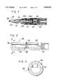
- FIG. 1is an enlarged cross-sectional view of the surgical instrument without the implement or sleeve installed and is constructed in accordance with the invention.
- FIG. 2is a cross-sectional view of the forward end of the surgical instrument with the implement and sleeve installed.
- FIG. 3is an enlarged cross-sectional view of the tubular shaft and is constructed in accordance with the invention.
- FIG. 4is an enlarged cross-sectional view of the tubular shaft in FIG. 3 taken along the line 4--4.
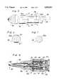
- FIG. 5is an enlarged partial side view of the tool implement.
- FIG. 6is an enlarged cross-sectional view of the tool implement of FIG. 5 taken along the line 6--6.
- FIG. 7is an enlarged cross-sectional view of the tool implement of FIG. 5 taken along the line 7--7.
- FIG. 8is an enlarged cross-sectional view of the tool in a second mode constructed in accordance with the invention.
- Instrument 10used for the resection of tissue in surgical procedures is shown.
- Instrument 10is provided with a fluid driven motor (not shown) having an air conduit (not shown) which provides a source of pressurized air to the motor.
- the motordrives a spindle 12 inside a motor housing 120 which has external threads 122.
- Motor housing 120threadingly engages an attachment 14 which contains internal threads 124.
- Spindle 12is rotated by the motor about a longitudinal axis.
- Connected to attachment 14is the base 16 of coupling 15 which is threaded onto a threaded neck 18 of attachment 14 by means of threads 20.
- support sleeve 22extends from and is joined at an end 24 of coupling 15 opposite base 16.
- Guide tube or support sleeve 22houses cutting implement 28 which has a shank 26.
- implement 28At one end of implement 28 is a cutting element 30.
- implement 28has a shank diameter of 1/8 inch for the forward portion 26a, beginning at the point where it attaches to cutting element 30.
- the rearward portion 26b of shank 26is reduced to a 3/32 inch diameter.
- two flats or shoulders 37are located at the junction between forward and rearward portions 26a and 26b.
- tang 34Opposite of cutting element 30 is a tang 34. Tang 34 is a keyed extension from rearward portion 26b. Either shoulders 37 or tang 34 may be used to apply torque to implement 28.
- base 16contains a cavity 32.
- the rearward end of a secondary or tubular shaft 43is contained within cavity 32.
- Tubular shaft 43contains internal threads 47 on this end.
- tubular shaft 43is essentially cylindrical with a central bore 44. Bore 44 closely receives shank rearward portion 26b, but is smaller than forward portion 26a.
- Boss 48has a threaded neck 45 which threads into threads 47. Threads 47 and threaded neck 45 are oriented to ensure that they do not become uncoupled during the operation of instrument 10.
- Boss 48has a hexagonally-shaped receptacle 50 for receiving a hexagonally-shaped neck 49 extending from spindle 12 so that boss 48 securely couples to spindle 12.
- Boss 48is provided so that tubular shaft 43 can mate with and be driven by spindle 12.
- Boss 48also has an elongated socket 38, which substantially coincides with the axis of implement 28, for receiving tang 34 of implement 28.
- Socket 38is formed so that it fits tang 34 in order to transfer torque to implement 28.
- Tubular shaft 43contains an inner lock or shoulder 52 upon which shoulder 54 of tang 34 lands and forces the correct orientation of implement 28.
- tubular shaft 43has two shoulders 56 on its forward end. Referring to FIGS. 4 and 6, shoulders 37 of implement 28 engage shoulders 56 when implement 28 is installed.
- Tubular shaft 43has a plurality of circular apertures 58 near its axial midpoint which extend radially outward from central bore 44. Each aperture 58 decreases in diameter towards central bore 44 to form a conical locking member seat 46.
- spherical locking members or balls 60fit within apertures 58 and engage an annular recess 62 in rearward shank portion 26b of implement 28.
- balls 60Prior to the installation of implement 28, balls 60 are free to roll or move within apertures 58, but are prevented from fully entering central bore 44 by locking member seats 46 located at the inner edge of apertures 58.
- balls 60engage recess 62 and prevent the axial movement of implement 28.
- tubular shaft 43rotates within cavity 32 of base 16 on three roller bearings.
- a first bearing 70is located between shoulders 56 and base 16.
- a second bearing 72is located between apertures 58 and a boss 74, which slidingly abuts the forward end of base 16.
- a third bearing 76is located between base 16 and a boss 78, which abuts the end of tubular shaft 43 that is secured to boss 48.
- Base 16has two, opposing circular apertures 80 forward of first bearing 70.
- Spherical locking members or balls 82fit within apertures 80 and extend into an annular recess 84 on sleeve 22.
- Balls 82operate with apertures 80 in exactly the same way as balls 60 operate with apertures 58. Balls 82 prevent the axial movement of sleeve 22 when it is installed in a cavity 86 of coupling 15.
- the first modecomprises a quick release mechanism that can engage and disengage both implement 28 and sleeve 22 simultaneously.
- Encircling base 16is a cylindrical collar 90. The lower end of collar 90 closely receives the end of base 16 that connects to attachment 14 so that collar 90 slides along the exterior of base 16 and attachment 14 for a short distance when moved between engaged and disengaged positions along lines parallel to the longitudinal axis of spindle 12.
- a coiled spring 92is located between base 16 and collar 90. One end of spring 92 lands on an outer shoulder 94 of base 16, while the other end of spring 92 lands on a rearward end or shoulder 98 of a cam sleeve 96.
- Cam sleeve 96is located near first bearing 70 and slidingly receives the forward end of base 16.
- Spring 92is axially biased to urge cam sleeve 96 away from shoulder 94.
- Cam sleeve 96is attached to collar 90 and boss 74 with screws 98 which extend through holes in each member such that cam sleeve 96, collar 90 and boss 74 move integrally and slidingly together.
- attachment 14may be removed from motor housing 120 and replaced by a different attachment 130, which is similar to attachment 14.
- Spindle 12is threaded onto a primary shaft 110 which is connected to the motor.
- Spindle 12 and primary shaft 110share a central bore 114 for receiving a different tool implement 132 with a shank diameter larger than that of implement 28.
- tool 132has an annular recess 134 on its shank 136, a cutting tip 138 on one end, and a tang 140 on the other end that acts as a torque shoulder.
- Tool 132is closely received by and fits within bore 114 until tang 140 mates with a receptacle 116 on the rearward end of primary shaft 110.
- Receptacle 116acts as a torque shoulder for transferring torque from the motor to the tool.
- Spindle 12has two apertures 120 forward of primary shaft 110.
- Balls 122fit within apertures 120 and extend into recess 134 on tool 132 to prevent its axial movement when tool 132 is installed.
- Balls 122operate with apertures 120 in exactly the same way as balls 60 operate with apertures 58.
- the second modealso comprises a quick release mechanism with a collar 142 that can slidingly engage and disengage both tool 132 and a tool support sleeve 144 simultaneously.
- This mechanismoperates in essentially the same way as the quick release mechanism described for the first mode.
- This inventionhas several advantages. It allows a conventional rotary machine to drive implements with smaller diameter shafts without additional modification, thereby increasing the versatility of the machine.
- the inventionutilizes a multi-faceted boss that can accommodate various-sized motor spindles to couple with the tubular shaft.
- the extra set of flats or shoulders on the tubular shaftincreases the durability of the implements by providing additional accommodation for torque on the implement. This is especially critical for implements formed from brittle materials such as tungsten carbide.
- the quick release coupling device of the inventionallows for easy removal, replacement, and conversion between sizes of implements in a much shorter period of time.
Landscapes
- Health & Medical Sciences (AREA)
- Engineering & Computer Science (AREA)
- Life Sciences & Earth Sciences (AREA)
- Surgery (AREA)
- Oral & Maxillofacial Surgery (AREA)
- Medical Informatics (AREA)
- Nuclear Medicine, Radiotherapy & Molecular Imaging (AREA)
- Dentistry (AREA)
- Mechanical Engineering (AREA)
- Biomedical Technology (AREA)
- Heart & Thoracic Surgery (AREA)
- Orthopedic Medicine & Surgery (AREA)
- Molecular Biology (AREA)
- Animal Behavior & Ethology (AREA)
- General Health & Medical Sciences (AREA)
- Public Health (AREA)
- Veterinary Medicine (AREA)
- Surgical Instruments (AREA)
Abstract
Description
Claims (14)
Priority Applications (1)
| Application Number | Priority Date | Filing Date | Title |
|---|---|---|---|
| US08/837,446US5893851A (en) | 1997-04-18 | 1997-04-18 | Multiple chuck resecting tool |
Applications Claiming Priority (1)
| Application Number | Priority Date | Filing Date | Title |
|---|---|---|---|
| US08/837,446US5893851A (en) | 1997-04-18 | 1997-04-18 | Multiple chuck resecting tool |
Publications (1)
| Publication Number | Publication Date |
|---|---|
| US5893851Atrue US5893851A (en) | 1999-04-13 |
Family
ID=25274464
Family Applications (1)
| Application Number | Title | Priority Date | Filing Date |
|---|---|---|---|
| US08/837,446Expired - LifetimeUS5893851A (en) | 1997-04-18 | 1997-04-18 | Multiple chuck resecting tool |
Country Status (1)
| Country | Link |
|---|---|
| US (1) | US5893851A (en) |
Cited By (47)
| Publication number | Priority date | Publication date | Assignee | Title |
|---|---|---|---|---|
| US5993453A (en)* | 1997-10-15 | 1999-11-30 | Huntington Medical Research Institutes | Controlled-depth bone cutter |
| WO2001001870A1 (en)* | 1999-07-01 | 2001-01-11 | Karl Storz Gmbh & Co. Kg | Medical, especially surgical, instrument |
| US6270087B1 (en)* | 1994-07-27 | 2001-08-07 | Mednext, Inc. | Tool shaft coupler |
| US6375577B1 (en) | 1999-10-27 | 2002-04-23 | Abbott Laboratories | Universal style coupling |
| US20020151902A1 (en)* | 2001-03-21 | 2002-10-17 | Medtronic, Inc. | Surgical instrument with rotary cutting member and quick release coupling arrangement |
| US20020165549A1 (en)* | 2001-04-30 | 2002-11-07 | Medtronic, Inc. | Surgical instrument and attachment |
| US20030023256A1 (en)* | 2001-03-21 | 2003-01-30 | Medtronic, Inc. D/B/A Medtronic Midas Rex | Surgical instrument with rotary cutting member and quick release coupling arrangement |
| US20030163134A1 (en)* | 2001-03-21 | 2003-08-28 | Medtronic, Inc. D/B/A Medtronic Midas Rex | Surgical instrument with rotary cutting member and quick release coupling arrangement |
| US20040122460A1 (en)* | 2002-12-20 | 2004-06-24 | Medtronic, Inc. | Surgical instrument with telescoping attachment |
| US6780189B2 (en) | 2002-06-07 | 2004-08-24 | Medtronic, Inc. | Surgical instrument with a collet locking and indexing system |
| US6783533B2 (en) | 2001-11-21 | 2004-08-31 | Sythes Ag Chur | Attachable/detachable reaming head for surgical reamer |
| US20040228702A1 (en)* | 2003-05-01 | 2004-11-18 | Lewmar Limited | Fixing assemblies and methods |
| US20050093392A1 (en)* | 2003-10-31 | 2005-05-05 | Medtronic, Inc. | Electric motor having nanocrystalline alloy component for use in surgical procedure |
| US20050192585A1 (en)* | 2004-02-27 | 2005-09-01 | Medtronic, Inc. | Surgical saw collet with closed drive ring |
| US20060041268A1 (en)* | 2004-08-17 | 2006-02-23 | Medtronic, Inc. | Surgical attachment instrument and method |
| US20060053974A1 (en)* | 2003-03-15 | 2006-03-16 | Aesculap Ag & Co. Kg | Coupling for a surgical rotary drive hand piece |
| US20060178672A1 (en)* | 2002-12-20 | 2006-08-10 | Medtronic, Inc. D/B/A Medtronic Midas Rex | Surgical instrument with angled attachment |
| US20060248624A1 (en)* | 2005-04-25 | 2006-11-09 | Pieczynski Darren E | Heat containment hand warming device |
| US20080246233A1 (en)* | 2004-03-15 | 2008-10-09 | Wienhold James L | Dual Size Tool-Bit Holder |
| US20090326540A1 (en)* | 2008-06-30 | 2009-12-31 | Medtronic Xomed, Inc. | Chuck for Reciprocating Surgical Instrument |
| US7810817B1 (en)* | 2006-11-20 | 2010-10-12 | Bradshaw Medical, Inc. | Holder for replaceable tools |
| US20140239599A1 (en)* | 2011-06-16 | 2014-08-28 | Von Arx Ag | Quick coupling system for fastening an interchangeable head on a press tool |
| US20150313612A1 (en)* | 2014-04-30 | 2015-11-05 | Gyrus Acmi, Inc., D.B.A. Olympus Surgical Technologies America | Rotary tool with improved coupling assembly |
| USD782042S1 (en) | 2015-03-25 | 2017-03-21 | Medtronic Ps Medical, Inc. | Surgical tool |
| USD790699S1 (en) | 2015-03-25 | 2017-06-27 | Medtronic Ps Medical, Inc. | Surgical tool |
| US9757129B2 (en) | 2013-07-08 | 2017-09-12 | Covidien Lp | Coupling member configured for use with surgical devices |
| USD800903S1 (en) | 2016-02-09 | 2017-10-24 | Medtronic Ps Medical, Inc. | Surgical tool |
| USD800906S1 (en) | 2015-03-25 | 2017-10-24 | Medtronic Ps Medical, Inc. | Surgical tool |
| USD800907S1 (en) | 2015-03-25 | 2017-10-24 | Medtronic Ps Medical, Inc. | Surgical tool |
| US20180055519A1 (en)* | 2016-08-31 | 2018-03-01 | Medtronic Ps Medical, Inc. | Multiple Connection Drive Shaft |
| US10080579B2 (en) | 2015-03-25 | 2018-09-25 | Medtronic Ps Medical, Inc. | Pin drive rotary surgical cutting tools and powered handpieces |
| US10314610B2 (en) | 2015-03-25 | 2019-06-11 | Medtronic Ps Medical, Inc. | Slanted drive axis rotary surgical cutting tools and powered handpieces |
| US10849634B2 (en) | 2018-06-20 | 2020-12-01 | Medtronic Xomed, Inc. | Coupling portion for rotary surgical cutting systems |
| US11103282B1 (en) | 2002-05-31 | 2021-08-31 | Teleflex Life Sciences Limited | Powered drivers, intraosseous devices and methods to access bone marrow |
| US11234683B2 (en) | 2002-05-31 | 2022-02-01 | Teleflex Life Sciences Limited | Assembly for coupling powered driver with intraosseous device |
| US11266441B2 (en) | 2002-05-31 | 2022-03-08 | Teleflex Life Sciences Limited | Penetrator assembly for accessing bone marrow |
| US11298202B2 (en) | 2002-05-31 | 2022-04-12 | Teleflex Life Sciences Limited | Biopsy devices and related methods |
| US11324521B2 (en) | 2002-05-31 | 2022-05-10 | Teleflex Life Sciences Limited | Apparatus and method to access bone marrow |
| US11337728B2 (en) | 2002-05-31 | 2022-05-24 | Teleflex Life Sciences Limited | Powered drivers, intraosseous devices and methods to access bone marrow |
| US11389222B2 (en)* | 2020-02-18 | 2022-07-19 | DePuy Synthes Products, Inc. | Medical pin removal tool |
| US11426249B2 (en) | 2006-09-12 | 2022-08-30 | Teleflex Life Sciences Limited | Vertebral access system and methods |
| US20220304703A1 (en)* | 2021-03-26 | 2022-09-29 | Depuy Ireland Unlimited Company | Surgical component connecting device, kit, and methods of use |
| US20230211480A1 (en)* | 2022-01-06 | 2023-07-06 | Techway Industrial Co., Ltd. | Structure for replacing shear wrench head |
| US11771439B2 (en) | 2007-04-04 | 2023-10-03 | Teleflex Life Sciences Limited | Powered driver |
| EP4321110A1 (en) | 2022-08-11 | 2024-02-14 | Aesculap AG | Shaft coupling and corresponding assembly method |
| US12256945B2 (en) | 2015-08-31 | 2025-03-25 | Medtronic Ps Medical, Inc. | Surgical burs |
| US12440902B2 (en) | 2024-01-08 | 2025-10-14 | Medtronic Ps Medical, Inc. | Pin drive rotary surgical cutting tools and powered handpieces |
Citations (7)
| Publication number | Priority date | Publication date | Assignee | Title |
|---|---|---|---|---|
| US3975032A (en)* | 1974-04-15 | 1976-08-17 | Minnesota Mining And Manufacturing Company | Surgical wire driving assembly |
| US4736742A (en)* | 1986-04-03 | 1988-04-12 | Minnesota Mining And Manufacturing Company | Device for driving tools used in orthopedic surgery |
| US5219174A (en)* | 1990-12-19 | 1993-06-15 | Synthes (U.S.A.) | Drill chuck for a drill to be used particularly for surgical purposes |
| US5222956A (en)* | 1992-07-06 | 1993-06-29 | Altair Instruments, Inc. | Surgical drill collet mechanism and bur |
| US5330480A (en)* | 1993-03-03 | 1994-07-19 | Codman & Shurtleff, Inc. | Surgical drill |
| US5490683A (en)* | 1994-07-27 | 1996-02-13 | Mednext Inc. | Tool shaft coupler |
| US5569256A (en)* | 1995-02-10 | 1996-10-29 | Midas Rex Pneumatic Tools, Inc. | Surgical resection tool with a double quick release |
- 1997
- 1997-04-18USUS08/837,446patent/US5893851A/ennot_activeExpired - Lifetime
Patent Citations (7)
| Publication number | Priority date | Publication date | Assignee | Title |
|---|---|---|---|---|
| US3975032A (en)* | 1974-04-15 | 1976-08-17 | Minnesota Mining And Manufacturing Company | Surgical wire driving assembly |
| US4736742A (en)* | 1986-04-03 | 1988-04-12 | Minnesota Mining And Manufacturing Company | Device for driving tools used in orthopedic surgery |
| US5219174A (en)* | 1990-12-19 | 1993-06-15 | Synthes (U.S.A.) | Drill chuck for a drill to be used particularly for surgical purposes |
| US5222956A (en)* | 1992-07-06 | 1993-06-29 | Altair Instruments, Inc. | Surgical drill collet mechanism and bur |
| US5330480A (en)* | 1993-03-03 | 1994-07-19 | Codman & Shurtleff, Inc. | Surgical drill |
| US5490683A (en)* | 1994-07-27 | 1996-02-13 | Mednext Inc. | Tool shaft coupler |
| US5569256A (en)* | 1995-02-10 | 1996-10-29 | Midas Rex Pneumatic Tools, Inc. | Surgical resection tool with a double quick release |
Cited By (81)
| Publication number | Priority date | Publication date | Assignee | Title |
|---|---|---|---|---|
| US6270087B1 (en)* | 1994-07-27 | 2001-08-07 | Mednext, Inc. | Tool shaft coupler |
| US5993453A (en)* | 1997-10-15 | 1999-11-30 | Huntington Medical Research Institutes | Controlled-depth bone cutter |
| WO2001001870A1 (en)* | 1999-07-01 | 2001-01-11 | Karl Storz Gmbh & Co. Kg | Medical, especially surgical, instrument |
| US6706056B2 (en) | 1999-07-01 | 2004-03-16 | Karl Storz Gmbh & Co. Kg | Medical, especially surgical, instrument |
| US6375577B1 (en) | 1999-10-27 | 2002-04-23 | Abbott Laboratories | Universal style coupling |
| US7001391B2 (en) | 2001-03-21 | 2006-02-21 | Medtronic, Inc. | Surgical instrument with rotary cutting member and quick release coupling arrangement |
| US20020151902A1 (en)* | 2001-03-21 | 2002-10-17 | Medtronic, Inc. | Surgical instrument with rotary cutting member and quick release coupling arrangement |
| US20030023256A1 (en)* | 2001-03-21 | 2003-01-30 | Medtronic, Inc. D/B/A Medtronic Midas Rex | Surgical instrument with rotary cutting member and quick release coupling arrangement |
| US20030163134A1 (en)* | 2001-03-21 | 2003-08-28 | Medtronic, Inc. D/B/A Medtronic Midas Rex | Surgical instrument with rotary cutting member and quick release coupling arrangement |
| US7066940B2 (en) | 2001-03-21 | 2006-06-27 | Medtronic, Inc. | Surgical instrument with rotary cutting member and quick release coupling arrangement |
| US7011661B2 (en) | 2001-03-21 | 2006-03-14 | Medtronic, Inc. | Surgical instrument with rotary cutting member and quick release coupling arrangement |
| US20020165549A1 (en)* | 2001-04-30 | 2002-11-07 | Medtronic, Inc. | Surgical instrument and attachment |
| US6783533B2 (en) | 2001-11-21 | 2004-08-31 | Sythes Ag Chur | Attachable/detachable reaming head for surgical reamer |
| US11324521B2 (en) | 2002-05-31 | 2022-05-10 | Teleflex Life Sciences Limited | Apparatus and method to access bone marrow |
| US11298202B2 (en) | 2002-05-31 | 2022-04-12 | Teleflex Life Sciences Limited | Biopsy devices and related methods |
| US11291472B2 (en) | 2002-05-31 | 2022-04-05 | Teleflex Life Sciences Limited | Powered drivers, intraosseous devices and methods to access bone marrow |
| US11266441B2 (en) | 2002-05-31 | 2022-03-08 | Teleflex Life Sciences Limited | Penetrator assembly for accessing bone marrow |
| US11234683B2 (en) | 2002-05-31 | 2022-02-01 | Teleflex Life Sciences Limited | Assembly for coupling powered driver with intraosseous device |
| US11337728B2 (en) | 2002-05-31 | 2022-05-24 | Teleflex Life Sciences Limited | Powered drivers, intraosseous devices and methods to access bone marrow |
| US11103282B1 (en) | 2002-05-31 | 2021-08-31 | Teleflex Life Sciences Limited | Powered drivers, intraosseous devices and methods to access bone marrow |
| US6780189B2 (en) | 2002-06-07 | 2004-08-24 | Medtronic, Inc. | Surgical instrument with a collet locking and indexing system |
| US20060178672A1 (en)* | 2002-12-20 | 2006-08-10 | Medtronic, Inc. D/B/A Medtronic Midas Rex | Surgical instrument with angled attachment |
| US20040122460A1 (en)* | 2002-12-20 | 2004-06-24 | Medtronic, Inc. | Surgical instrument with telescoping attachment |
| US20080208195A1 (en)* | 2002-12-20 | 2008-08-28 | Medtronic, Inc. | Surgical Instrument With Telescoping Attachment |
| US7549992B2 (en) | 2002-12-20 | 2009-06-23 | Medtronic, Inc. | Surgical instrument with angled attachment |
| US7559927B2 (en) | 2002-12-20 | 2009-07-14 | Medtronic Xomed, Inc. | Surgical instrument with telescoping attachment |
| US9066729B2 (en) | 2002-12-20 | 2015-06-30 | Medtronic, Inc. | Surgical instrument with telescoping attachment |
| US8518065B2 (en) | 2002-12-20 | 2013-08-27 | Medtronic, Inc. | Surgical instrument with telescoping attachment |
| US20060053974A1 (en)* | 2003-03-15 | 2006-03-16 | Aesculap Ag & Co. Kg | Coupling for a surgical rotary drive hand piece |
| US20040228702A1 (en)* | 2003-05-01 | 2004-11-18 | Lewmar Limited | Fixing assemblies and methods |
| US20050093392A1 (en)* | 2003-10-31 | 2005-05-05 | Medtronic, Inc. | Electric motor having nanocrystalline alloy component for use in surgical procedure |
| US20050192585A1 (en)* | 2004-02-27 | 2005-09-01 | Medtronic, Inc. | Surgical saw collet with closed drive ring |
| US8292304B2 (en) | 2004-03-15 | 2012-10-23 | Insty-Bit, Llc | Dual size tool-bit holder |
| US20080246233A1 (en)* | 2004-03-15 | 2008-10-09 | Wienhold James L | Dual Size Tool-Bit Holder |
| US20110140376A1 (en)* | 2004-03-15 | 2011-06-16 | Wienhold James L | Dual Size Tool-Bit Holder |
| US7896355B2 (en)* | 2004-03-15 | 2011-03-01 | Wienhold James L | Dual size tool-bit holder |
| US7658740B2 (en)* | 2004-08-17 | 2010-02-09 | Medtronic, Inc. | Surgical attachment instrument and method |
| US20060041268A1 (en)* | 2004-08-17 | 2006-02-23 | Medtronic, Inc. | Surgical attachment instrument and method |
| US20060248624A1 (en)* | 2005-04-25 | 2006-11-09 | Pieczynski Darren E | Heat containment hand warming device |
| US12089972B2 (en) | 2006-09-12 | 2024-09-17 | Teleflex Life Sciences Limited | Apparatus and methods for biopsy and aspiration of bone marrow |
| US11426249B2 (en) | 2006-09-12 | 2022-08-30 | Teleflex Life Sciences Limited | Vertebral access system and methods |
| US7810817B1 (en)* | 2006-11-20 | 2010-10-12 | Bradshaw Medical, Inc. | Holder for replaceable tools |
| US11771439B2 (en) | 2007-04-04 | 2023-10-03 | Teleflex Life Sciences Limited | Powered driver |
| US10080568B2 (en) | 2008-06-30 | 2018-09-25 | Medtronic Xomed, Inc. | Chuck for reciprocating surgical instrument |
| US20090326540A1 (en)* | 2008-06-30 | 2009-12-31 | Medtronic Xomed, Inc. | Chuck for Reciprocating Surgical Instrument |
| US8465492B2 (en) | 2008-06-30 | 2013-06-18 | Medtronic Xomed, Inc. | Chuck for reciprocating surgical instrument |
| US9573335B2 (en)* | 2011-06-16 | 2017-02-21 | Von Arx Ag | Quick coupling system for fastening an interchangeable head on a press tool |
| US20140239599A1 (en)* | 2011-06-16 | 2014-08-28 | Von Arx Ag | Quick coupling system for fastening an interchangeable head on a press tool |
| US10624637B2 (en) | 2013-07-08 | 2020-04-21 | Covidien Lp | Coupling member configured for use with surgical devices |
| US9757129B2 (en) | 2013-07-08 | 2017-09-12 | Covidien Lp | Coupling member configured for use with surgical devices |
| US11497498B2 (en) | 2013-07-08 | 2022-11-15 | Covidien Lp | Coupling member configured for use with surgical devices |
| US20150313612A1 (en)* | 2014-04-30 | 2015-11-05 | Gyrus Acmi, Inc., D.B.A. Olympus Surgical Technologies America | Rotary tool with improved coupling assembly |
| US10278712B2 (en) | 2014-04-30 | 2019-05-07 | Gyrus Acmi, Inc. | Rotary tool with improved coupling assembly |
| US9414848B2 (en) | 2014-04-30 | 2016-08-16 | Gyrus Acmi, Inc. | Rotary tool with improved coupling assembly |
| US9504478B2 (en)* | 2014-04-30 | 2016-11-29 | Gyrus ACMI , Inc. | Rotary tool with improved coupling assembly |
| USD782042S1 (en) | 2015-03-25 | 2017-03-21 | Medtronic Ps Medical, Inc. | Surgical tool |
| US11154319B2 (en) | 2015-03-25 | 2021-10-26 | Medtronic Ps Medical, Inc. | Slanted drive axis rotary surgical cutting tools and powered handpieces |
| US10905453B2 (en) | 2015-03-25 | 2021-02-02 | Medtronic Ps Medical, Inc. | Pin drive rotary surgical cutting tools and powered handpieces |
| US10314610B2 (en) | 2015-03-25 | 2019-06-11 | Medtronic Ps Medical, Inc. | Slanted drive axis rotary surgical cutting tools and powered handpieces |
| US10080579B2 (en) | 2015-03-25 | 2018-09-25 | Medtronic Ps Medical, Inc. | Pin drive rotary surgical cutting tools and powered handpieces |
| US11864784B2 (en) | 2015-03-25 | 2024-01-09 | Medtronic Ps Medical, Inc. | Pin drive rotary surgical cutting tools and powered handpieces |
| USD800907S1 (en) | 2015-03-25 | 2017-10-24 | Medtronic Ps Medical, Inc. | Surgical tool |
| USD800906S1 (en) | 2015-03-25 | 2017-10-24 | Medtronic Ps Medical, Inc. | Surgical tool |
| USD790699S1 (en) | 2015-03-25 | 2017-06-27 | Medtronic Ps Medical, Inc. | Surgical tool |
| US12256945B2 (en) | 2015-08-31 | 2025-03-25 | Medtronic Ps Medical, Inc. | Surgical burs |
| USD800903S1 (en) | 2016-02-09 | 2017-10-24 | Medtronic Ps Medical, Inc. | Surgical tool |
| US11666344B2 (en)* | 2016-08-31 | 2023-06-06 | Medtronic Ps Medical, Inc. | Multiple connection drive shaft |
| US11076871B2 (en)* | 2016-08-31 | 2021-08-03 | Medtronic Ps Medical, Inc. | Multiple connection drive shaft |
| US20180055519A1 (en)* | 2016-08-31 | 2018-03-01 | Medtronic Ps Medical, Inc. | Multiple Connection Drive Shaft |
| US20210353307A1 (en)* | 2016-08-31 | 2021-11-18 | Medtronic Ps Medical, Inc. | Multiple Connection Drive Shaft |
| US10849634B2 (en) | 2018-06-20 | 2020-12-01 | Medtronic Xomed, Inc. | Coupling portion for rotary surgical cutting systems |
| US12137918B2 (en) | 2018-06-20 | 2024-11-12 | Medtronic Xomed, Inc. | Coupling portion for rotary surgical cutting systems |
| US11918267B2 (en) | 2020-02-18 | 2024-03-05 | DePuy Synthes Products, Inc. | Medical pin removal tool |
| US11389222B2 (en)* | 2020-02-18 | 2022-07-19 | DePuy Synthes Products, Inc. | Medical pin removal tool |
| US20220304703A1 (en)* | 2021-03-26 | 2022-09-29 | Depuy Ireland Unlimited Company | Surgical component connecting device, kit, and methods of use |
| US12082826B2 (en)* | 2021-03-26 | 2024-09-10 | Depuy Ireland Unlimited Company, Loughbeg Industrial Estate | Surgical component connecting device, kit, and methods of use |
| US20230211480A1 (en)* | 2022-01-06 | 2023-07-06 | Techway Industrial Co., Ltd. | Structure for replacing shear wrench head |
| US12311509B2 (en)* | 2022-01-06 | 2025-05-27 | Techway Industrial Co., Ltd. | Structure for replacing shear wrench head |
| DE102022120351A1 (en)* | 2022-08-11 | 2024-02-22 | Aesculap Ag | Shaft coupling and associated assembly procedure |
| EP4321110A1 (en) | 2022-08-11 | 2024-02-14 | Aesculap AG | Shaft coupling and corresponding assembly method |
| US12440902B2 (en) | 2024-01-08 | 2025-10-14 | Medtronic Ps Medical, Inc. | Pin drive rotary surgical cutting tools and powered handpieces |
Similar Documents
| Publication | Publication Date | Title |
|---|---|---|
| US5893851A (en) | Multiple chuck resecting tool | |
| US5741263A (en) | Mutiple flat quick release coupling | |
| US11826058B2 (en) | Surgical drill instrument with motor and locking mechanism to receive an attachment and a cutting burr | |
| US5989257A (en) | Redundant safety lock mechanism | |
| AU2020201756B2 (en) | Dynamic locking device | |
| US5601560A (en) | Tool bit for a motor driven surgical instrument | |
| EP3137249B1 (en) | Rotary tool with improved coupling assembly | |
| EP2693957B1 (en) | Surgical drill instrument with motor and locking mechanism to receive an attachment and a cutting burr | |
| US5505737A (en) | Quick release coupling for a dissecting tool | |
| US8518065B2 (en) | Surgical instrument with telescoping attachment | |
| AU673468B2 (en) | Keyless drill chuck | |
| US4067403A (en) | Wire driver handpiece | |
| US4813413A (en) | Surgical instrument with detachable tool member | |
| US7955320B2 (en) | Precision spindle instrument holder for surgical instrument |
Legal Events
| Date | Code | Title | Description |
|---|---|---|---|
| AS | Assignment | Owner name:MIDAS REX PNEUMATIC TOOLS, INC., TEXAS Free format text:ASSIGNMENT OF ASSIGNORS INTEREST;ASSIGNORS:UMBER, RAY E.;ESTES, LARRY DALE;SCANTLEBURY, TOWNSEND R.;REEL/FRAME:008524/0204 Effective date:19970218 | |
| AS | Assignment | Owner name:MIDAS REX, L.P., TEXAS Free format text:ASSIGNMENT OF ASSIGNORS INTEREST;ASSIGNOR:MIDAS REX PNEUMATIC TOOLS, INC., A CORPORATION OF TEXAS;REEL/FRAME:009095/0536 Effective date:19980317 | |
| STCF | Information on status: patent grant | Free format text:PATENTED CASE | |
| FEPP | Fee payment procedure | Free format text:PAYOR NUMBER ASSIGNED (ORIGINAL EVENT CODE: ASPN); ENTITY STATUS OF PATENT OWNER: LARGE ENTITY | |
| FEPP | Fee payment procedure | Free format text:PAT HOLDER NO LONGER CLAIMS SMALL ENTITY STATUS, ENTITY STATUS SET TO UNDISCOUNTED (ORIGINAL EVENT CODE: STOL); ENTITY STATUS OF PATENT OWNER: LARGE ENTITY | |
| REFU | Refund | Free format text:REFUND - SURCHARGE, PETITION TO ACCEPT PYMT AFTER EXP, UNINTENTIONAL (ORIGINAL EVENT CODE: R2551); ENTITY STATUS OF PATENT OWNER: LARGE ENTITY | |
| FPAY | Fee payment | Year of fee payment:4 | |
| FEPP | Fee payment procedure | Free format text:ENTITY STATUS SET TO UNDISCOUNTED (ORIGINAL EVENT CODE: BIG.); ENTITY STATUS OF PATENT OWNER: LARGE ENTITY | |
| FPAY | Fee payment | Year of fee payment:8 | |
| FPAY | Fee payment | Year of fee payment:12 |