US5893488A - Bone cement injector gun - Google Patents
Bone cement injector gunDownload PDFInfo
- Publication number
- US5893488A US5893488AUS08/877,324US87732497AUS5893488AUS 5893488 AUS5893488 AUS 5893488AUS 87732497 AUS87732497 AUS 87732497AUS 5893488 AUS5893488 AUS 5893488A
- Authority
- US
- United States
- Prior art keywords
- fulcrum
- trigger
- housing
- gate
- cartridge
- Prior art date
- Legal status (The legal status is an assumption and is not a legal conclusion. Google has not performed a legal analysis and makes no representation as to the accuracy of the status listed.)
- Expired - Lifetime
Links
Images


Classifications
- B—PERFORMING OPERATIONS; TRANSPORTING
- B05—SPRAYING OR ATOMISING IN GENERAL; APPLYING FLUENT MATERIALS TO SURFACES, IN GENERAL
- B05C—APPARATUS FOR APPLYING FLUENT MATERIALS TO SURFACES, IN GENERAL
- B05C17/00—Hand tools or apparatus using hand held tools, for applying liquids or other fluent materials to, for spreading applied liquids or other fluent materials on, or for partially removing applied liquids or other fluent materials from, surfaces
- B05C17/005—Hand tools or apparatus using hand held tools, for applying liquids or other fluent materials to, for spreading applied liquids or other fluent materials on, or for partially removing applied liquids or other fluent materials from, surfaces for discharging material from a reservoir or container located in or on the hand tool through an outlet orifice by pressure without using surface contacting members like pads or brushes
- B05C17/01—Hand tools or apparatus using hand held tools, for applying liquids or other fluent materials to, for spreading applied liquids or other fluent materials on, or for partially removing applied liquids or other fluent materials from, surfaces for discharging material from a reservoir or container located in or on the hand tool through an outlet orifice by pressure without using surface contacting members like pads or brushes with manually mechanically or electrically actuated piston or the like
- A—HUMAN NECESSITIES
- A61—MEDICAL OR VETERINARY SCIENCE; HYGIENE
- A61B—DIAGNOSIS; SURGERY; IDENTIFICATION
- A61B17/00—Surgical instruments, devices or methods
- A61B17/56—Surgical instruments or methods for treatment of bones or joints; Devices specially adapted therefor
- A61B17/58—Surgical instruments or methods for treatment of bones or joints; Devices specially adapted therefor for osteosynthesis, e.g. bone plates, screws or setting implements
- A61B17/88—Osteosynthesis instruments; Methods or means for implanting or extracting internal or external fixation devices
- A61B17/8802—Equipment for handling bone cement or other fluid fillers
- A61B17/8805—Equipment for handling bone cement or other fluid fillers for introducing fluid filler into bone or extracting it
- A61B17/8822—Equipment for handling bone cement or other fluid fillers for introducing fluid filler into bone or extracting it characterised by means facilitating expulsion of fluid from the introducer, e.g. a screw pump plunger, hydraulic force transmissions, application of vibrations or a vacuum
- A—HUMAN NECESSITIES
- A61—MEDICAL OR VETERINARY SCIENCE; HYGIENE
- A61B—DIAGNOSIS; SURGERY; IDENTIFICATION
- A61B17/00—Surgical instruments, devices or methods
- A61B17/56—Surgical instruments or methods for treatment of bones or joints; Devices specially adapted therefor
- A61B17/58—Surgical instruments or methods for treatment of bones or joints; Devices specially adapted therefor for osteosynthesis, e.g. bone plates, screws or setting implements
- A61B17/88—Osteosynthesis instruments; Methods or means for implanting or extracting internal or external fixation devices
- A61B17/8802—Equipment for handling bone cement or other fluid fillers
- A61B17/8833—Osteosynthesis tools specially adapted for handling bone cement or fluid fillers; Means for supplying bone cement or fluid fillers to introducing tools, e.g. cartridge handling means
- Y—GENERAL TAGGING OF NEW TECHNOLOGICAL DEVELOPMENTS; GENERAL TAGGING OF CROSS-SECTIONAL TECHNOLOGIES SPANNING OVER SEVERAL SECTIONS OF THE IPC; TECHNICAL SUBJECTS COVERED BY FORMER USPC CROSS-REFERENCE ART COLLECTIONS [XRACs] AND DIGESTS
- Y10—TECHNICAL SUBJECTS COVERED BY FORMER USPC
- Y10T—TECHNICAL SUBJECTS COVERED BY FORMER US CLASSIFICATION
- Y10T74/00—Machine element or mechanism
- Y10T74/15—Intermittent grip type mechanical movement
- Y10T74/1526—Oscillation or reciprocation to intermittent unidirectional motion
- Y10T74/1553—Lever actuator
- Y—GENERAL TAGGING OF NEW TECHNOLOGICAL DEVELOPMENTS; GENERAL TAGGING OF CROSS-SECTIONAL TECHNOLOGIES SPANNING OVER SEVERAL SECTIONS OF THE IPC; TECHNICAL SUBJECTS COVERED BY FORMER USPC CROSS-REFERENCE ART COLLECTIONS [XRACs] AND DIGESTS
- Y10—TECHNICAL SUBJECTS COVERED BY FORMER USPC
- Y10T—TECHNICAL SUBJECTS COVERED BY FORMER US CLASSIFICATION
- Y10T74/00—Machine element or mechanism
- Y10T74/15—Intermittent grip type mechanical movement
- Y10T74/1558—Grip units and features
- Y10T74/1587—Grip features
- Y10T74/1598—Driven ratchet-bar and power dog
- Y—GENERAL TAGGING OF NEW TECHNOLOGICAL DEVELOPMENTS; GENERAL TAGGING OF CROSS-SECTIONAL TECHNOLOGIES SPANNING OVER SEVERAL SECTIONS OF THE IPC; TECHNICAL SUBJECTS COVERED BY FORMER USPC CROSS-REFERENCE ART COLLECTIONS [XRACs] AND DIGESTS
- Y10—TECHNICAL SUBJECTS COVERED BY FORMER USPC
- Y10T—TECHNICAL SUBJECTS COVERED BY FORMER US CLASSIFICATION
- Y10T74/00—Machine element or mechanism
- Y10T74/20—Control lever and linkage systems
- Y10T74/20558—Variable output force
- Y—GENERAL TAGGING OF NEW TECHNOLOGICAL DEVELOPMENTS; GENERAL TAGGING OF CROSS-SECTIONAL TECHNOLOGIES SPANNING OVER SEVERAL SECTIONS OF THE IPC; TECHNICAL SUBJECTS COVERED BY FORMER USPC CROSS-REFERENCE ART COLLECTIONS [XRACs] AND DIGESTS
- Y10—TECHNICAL SUBJECTS COVERED BY FORMER USPC
- Y10T—TECHNICAL SUBJECTS COVERED BY FORMER US CLASSIFICATION
- Y10T74/00—Machine element or mechanism
- Y10T74/20—Control lever and linkage systems
- Y10T74/20576—Elements
- Y10T74/20582—Levers
- Y10T74/206—Adjustable
Definitions
- the present inventionrelates to injector guns for dispensing pastes, and more particularly, to injector guns that can dispense paste from a cartridge both at low pressure and high volume for filling a void and at high pressure and low volume for pressurizing the paste in the void.
- the present inventionfurther includes means for connecting the injector gun to cartridges having different diameters.
- Prior art injector gunshave a trigger mechanism that includes a trigger in the form of a lever.
- the triggerincludes an input end, an output end and a fulcrum between the ends. When the input end is squeezed by the user, the trigger pivots about the fulcrum causing the output end to move.
- the mechanical advantage of an injector gunis the amount the force applied to the input end is multiplied at the output end and can be calculated as the ratio of the length of the trigger from the fulcrum to the input end over the length of the trigger from the fulcrum to the output end.
- a high mechanical advantagemultiplies the force more but generates less motion at the output end than does a low mechanical advantage. Therefore, a high mechanical advantage facilitates generating a high pressure in the paste but extrudes a low volume of paste whereas a low mechanical advantage generates a low pressure in the paste but extrudes a high volume of paste.
- a typical application for paste injector gunsis for dispensing bone cement from a cartridge into the intramedullary canal of the femur.
- Millerdiscloses such an injector gun in U.S. Pat. 4,338,925.
- Millerteaches the advantage of improved implant fixation that results from pressurizing the cement after filling the canal in order to force the cement into bony interstices. Therefore, Miller requires an injector gun with a relatively high mechanical advantage.
- Miller's injector gunutilizes a trigger mechanism with a constant mechanical advantage that is a compromise between a low mechanical advantage that delivers a high flow rate for rapid filling and a high mechanical advantage that delivers high pressure for pressurizing the cement.
- the surgeonmust squeeze the trigger faster.
- the surgeonmust squeeze the trigger harder.
- Changteaches a mechanism that includes a bearing element that is adjustable up and down on the trigger and held in place by a set screw. By moving the bearing element, the output length of the trigger is changed and thus the mechanical advantage is changed.
- U.S. Pat. No. 5,381,931Chang teaches a different mechanism for selectively lengthening the output length of the trigger comprising an eccentric rotatable element attached to the output end of the trigger.
- Nicteaches another mechanism for changing mechanical advantage.
- the upper end of a trigger 70includes an enlarged head 74 which carries a low force/large displacement drive pawl 80 and a high force/low displacement drive pawl 81.
- the pawlsare biased by springs 86 and 87 into engagement with teeth 54 on rod 50.
- the low force pawl 80controls the advancement of the rod 50 because of its longer travel. If high force/low displacement rod advancement is desired, switch lever 92 is moved downwardly which causes it to contact push-down pin 94 which in turn moves low force pawl 80 out of engagement with the teeth 54 as shown in FIG. 5.
- a disadvantage of prior art injector guns with user adjustable mechanical advantagesis the need for additional parts and the resulting complexity in the trigger mechanism.
- a further disadvantage of prior art cement injector gunsis that they are configured to connect only to a cement cartridge having a single specified diameter. These prior art cement injector guns are therefore incapable of dispensing cement from differently sized cartridges such as from different manufacturers or different styles or sizes from the same manufacturer.
- the present inventionsolves these problems of the prior art by providing in a first embodiment a paste injector gun, especially adapted for injecting bone cement, having first and second mechanical advantages corresponding to different portions of the trigger stroke.
- the first mechanical advantageis greater than the second such that the first facilitates pressurizing the bone cement and the second facilitates high volume dispensing of the bone cement.
- the two mechanical advantagesare accomplished by providing a trigger mechanism with a trigger lever pivotably connected to a drive plate at the output end.
- the trigger mechanismincludes two fulcrums which provide two sequential centers of rotation. In the initial position, the first fulcrum is engaged. As the trigger is squeezed, a high mechanical advantage enables cement pressurization because the first fulcrum is close to the output end of the trigger lever. At the end of this first stage of trigger travel, the second fulcrum is engaged. During the second stage of trigger travel, the trigger lever pivots about the second fulcrum. This results in a higher flow volume because the second pivot point is further from the output end of the trigger lever. With the present invention there are no screws or switches which must be adjusted to change mechanical advantage.
- the two mechanical advantagesare designed into each squeeze of the trigger. The first portion of the trigger stroke produces high pressure and the second portion of the trigger stroke produces high flow volume. If high flow is desired, full strokes are used. If high pressure is desired, short strokes are used.
- the present inventionalso includes a second embodiment having a pair of fulcrums mounted on the handle opposite the trigger.
- One of the fulcrumsis rotatable between a first position in which it is engageable with the trigger and a second position in which it is not engageable with the trigger.
- a knob connected to the rotatable fulcrumextends from the housing and facilitates moving the rotatable fulcrum between the first and second positions. When the rotatable fulcrum is in the first, engaging position the rotatable fulcrum engages the trigger and provides a relatively low mechanical advantage and high fill rate.
- the injector gun of the present inventionalso includes a pair of U-shaped slots for gripping a bone cement containing cartridge.
- One of the slotsis sized to accept a large cement cartridge.
- the other slotis sized to accept a small cement cartridge.
- One embodimentincludes a hinged cartridge retention gate that closes the U-shaped slot for positive retention of the cartridge.
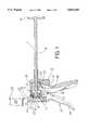
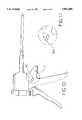
- FIG. 1is a side cross-sectional view of the cement injector gun of the present invention.
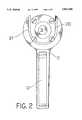
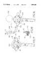
- FIG. 2is an end view of the cement injector gun of FIG. 1.
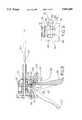
- FIGS. 3-5are side cross-sectional views of the trigger mechanism of the cement injector gun of FIG. 1 showing the operation of the trigger.
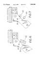
- FIG. 6is a side cross-sectional view of an alternative embodiment of the trigger mechanism of the cement injector gun of the present invention.
- FIG. 7is a side cross-sectional view of another alternative embodiment of the trigger mechanism of the cement injector gun of the present invention.
- FIG. 8is a side cross-sectional view of an alternative embodiment of the cement injector gun of the present invention.
- FIG. 9is a partial front view of the cement gun of FIG. 8 showing the two fulcrums.
- FIG. 10is a side view of the cement injector gun of FIG. 8.
- FIG. 11is a side detail view of the cement gun of FIG. 8 showing the two knob positions.
- FIGS. 12-13are side cross-sectional views of the cement injector gun of FIG. 8 showing the trigger actuation with the rotatable fulcrum in a first position.
- FIGS. 14-15are side cross-sectional views of the cement injector gun of FIG. 8 showing the trigger actuation with the rotatable fulcrum in a second position.
- FIG. 16is a front view of the cement injector gun of FIG. 8 showing the hinged cartridge retention gate in the open position.
- FIG. 17is a front view of the cement injector gun of FIG. 8 showing the hinged cartridge retention gate in the closed position.
- FIG. 18is a cross-sectional view of the cement injector gun of FIG. 16 showing the locking mechanism of the hinged cartridge retention gate.
- FIGS. 1 and 2depict a cement injector gun according to the present invention.
- a shaft 1is mounted for axial translation within a housing 2.
- the shaftincludes teeth 3 formed on a portion of its circumference and along its length.
- a handle 4is attached to one end of the shaft 1 and a shaft plate 5 is attached to the other end of the shaft 1.
- the shaft plate 5contains a recess 6 in its back side.
- a spring loaded plunger 7is mounted in the housing behind the shaft plate 5 such that when the teeth 3 are oriented downwardly, the plunger 7 is aligned with the recess 6.
- a drive plate 8is mounted for axial translation within the housing 2 and is coaxial with and surrounds the shaft 1.
- a return spring 9biases the drive plate 8 rearwardly in the housing.
- the drive plate 8carries a drive ratchet 10 rotatably mounted on the drive plate 8.
- a springbiases the drive ratchet 10 into contact with the shaft 1 such that the drive ratchet 10 will engage the teeth 3 when they are oriented downwardly.
- a retaining ratchet 11is rotatably mounted on the housing 2 and it is also spring biased into contact with the shaft 1 such that the retaining ratchet 11 will engage the teeth 3 when they are oriented downwardly.
- the injector gunincludes a trigger having a trigger lever 12 pivotally attached to the drive plate 8 at the trigger lever's output end 13. The input end 14 of the trigger lever 12 extends from the housing 2.
- the trigger lever 12also includes first and second bearing portions 15 and 16. First and second fulcrums, 17 and 18, are attached to the housing 2 in alignment with the first and second bearing portions 15 and 16. In the embodiment shown in FIG.
- a cartridge adapter 19is mounted on the front of the housing 2.
- the cartridge adapter 19contains first and second U-shaped slots, 20 and 21, lying on a common axis in axial alignment with the shaft 1.
- the U-shaped slotslie in parallel planes to one another.
- the second U-shaped slot 21has a larger radius than the first U-shaped slot 20.
- the U-shaped slotsare shaped to engage a cartridge 24 having a rim 25.
- Each U-shaped slotincludes a peripheral groove 22 and 23 to engage the rim 25 to prevent the cartridge from moving forward as the shaft presses against the cartridge.
- the first U-shaped slotis at least 10% narrower, preferably at least 20% narrower than the second slot. Therefore, first U-shaped slot 20 is sized for a small cartridge and the second U-shaped slot 21 is sized for a large cartridge.
- the first U-shaped slot 20is positioned on the common axis nearer to the trigger mechanism than the second U-shaped slot 21 such that a cartridge 24 engaged with the first U-shaped slot 20 will extend through the second U-shaped slot 21 and a cartridge engaged with the second U-shaped slot 21 will not extend through the first U-shaped slot 20.
- the shaft 1is then pulled backward until the plunger 7 is depressed and the shaft plate 5 is fully seated in the housing 2.
- the handle 4is then rotated until the teeth 3 are in alignment with the ratchets 10 and 11.
- the recess 6will come into alignment with the plunger 7 and the plunger 7 will pop out to extend into the recess 6.
- the popping of the plunger 7 into the recess 6is thus an audible and tactile indicator of proper tooth-to-ratchet alignment.
- the triggeris squeezed by applying pressure to the input end 14 of the trigger lever 12.
- the triggerhas a range of rotation from the rest position shown in FIG. 3 to the stop position shown in FIG. 5.
- the range of rotationis divided into two stages.
- the first stageis from the initial rest position to an intermediate position where the center of rotation changes from the first fulcrum to the second fulcrum.
- the second stageis from this intermediate position to the stop position.
- the first bearing portion 15contacts the first fulcrum 17 providing a first center of rotation.
- the trigger lever 12pivots about the first fulcrum 17 causing the drive plate 8 and drive ratchet 10 to move forward.
- the drive ratchet 10presses against the teeth 3 thus driving the shaft 1 forward as well.
- the retaining ratchet 11pivots against its biasing spring and allows the teeth 3 to slip by it.
- the forward moving shaft plate 5engages the cartridge 24 and forces cement from it.
- the first mechanical advantageis relatively high and a small input force yields a large output force for driving the shaft forward.
- This high mechanical advantageallows a large amount of pressure to be generated in the cement to force cement into bony interstices.
- Corresponding to the high mechanical advantageis a small movement of the shaft equal to the distance between points A and B as shown in FIG. 4. This small shaft 1 movement dispenses a relatively low volume of cement.
- the trigger lever 12rotates about the first fulcrum 17 during the first 15° of trigger travel at which point it contacts the second fulcrum 18.
- the shaft 1preferably travels forward 2 teeth or a distance of about 0.1".
- the distance the shaft moves for each degree of trigger rotation about the first fulcrumis the first advancement rate.
- the trigger lever 12rotates about a second center of rotation provided by the second fulcrum 18 as shown in FIG. 5. Because the second fulcrum 18 is further from the output end 13, the second mechanical advantage is relatively low. Preferably, the second mechanical advantage is from 10% to 90% of the first mechanical advantage, more preferably 25% to 50%. Corresponding to this low mechanical advantage is a relatively large shaft movement corresponding to the distance between the points B and C. This large shaft movement dispenses a large volume of cement but less pressure can be generated in the cement from a particular input force because of the lower mechanical advantage.
- this second stage of trigger travelcorresponds to approximately 20° of trigger lever 12 rotation and moves the shaft forward 6 teeth or a distance of about 0.31. The distance the shaft moves for each degree of trigger rotation about the second fulcrum is the second advancement rate. Preferably the second advancement rate is 1.1 to 10 times the first advancement rate, more preferably 2 to 4 times.
- the first portion of the trigger strokeproduces high pressure and the second portion of the trigger stroke produces high flow volume. If high flow is desired, full strokes are used. If high pressure is desired, short strokes are used. For a typical surgical procedure, full strokes would be used to fill a bone canal. Once the canal is filled, short strokes would be used to build fluid pressure in the cement in the bone canal.
- FIGS. 6 and 7depict alternative embodiments of the present invention.
- a trigger lever 30includes two fulcrums 31 and 32 in the form of raised areas or bumps.
- a bearing member 33is attached to the housing opposite the fulcrums 31 and 32.
- the first fulcrum 31initially contacts the bearing member 33 and the trigger lever 30 rotates about the first fulcrum 31 during the first stage of trigger travel.
- the trigger lever 30rotates about the second fulcrum 32.
- a trigger lever 40includes a flat bearing portion 41.
- Two fulcrums 42 and 43similar to those depicted in FIG. 1, are attached to the housing opposite the bearing portion 41.
- FIGS. 6 and 7provide the same function as the embodiment of FIG. 1. They provide a cement injector gun having a trigger mechanism with two stages of travel provided by two fulcrums that are engaged sequentially during the trigger stroke. The first stage is characterized by a high mechanical advantage for pressurizing the bone cement and the second stage is characterized by a low mechanical advantage for extruding a large volume of bone cement. The embodiments of FIGS. 6 and 7 differ from that of FIG. 1 only in the shape and placement of the fulcrums.
- FIGS. 8-17Another alternative embodiment of the present invention is shown in FIGS. 8-17.
- This rotatable fulcrum embodimentincludes a trigger 50 attached to a drive plate 52 at a pivot point 54.
- the trigger and drive plate assemblyis mounted for axial displacement in a housing 56 having an integral downwardly extending handle 58.
- a toothed shaft 60is also mounted for axial translation in the housing and extends through the drive plate 52.
- the drive plate 52carries a drive ratchet 62 which engages the shaft teeth 64.
- a pair of fulcrums 66 and 68, having bearing portions 70 and 72,are mounted on the handle 58 opposite the trigger 50.
- One of the fulcrums 66is rotatable between a first position in which it is engageable with the 50 trigger, as shown in FIGS.
- Another fulcrum 68is fixed and has a lower body portion 74 including a slot 76 and cross hole 78 perpendicular to the slot.
- the fixed fulcrumalso includes a rearwardly facing mounting hole 80.
- the fixed fulcrum 66is held in place by a screw 82 which extends through the hole 80 and into the handle 58.
- the rotatable fulcrum 66has a lower pivot portion 84 having a transverse hole 86.
- the lower pivot portion 84is mounted in the slot 76 for rotation.
- a pin 88extends through the cross hole 78 and transverse hole 86.
- a knob 90is mounted on the end of the pin 88.
- the pin 88is fixed relative to the rotatable fulcrum 66 and the knob 90 such as by press fitting or soldering.
- the pin 88is free to rotate in the cross hole 78.
- a spring loaded ball detent 92is mounted in the fixed fulcrum 68 such that its ball is biased against the lower pivot portion 84 of the rotatable fulcrum 66.
- Notches 94 and 96 in the lower pivot portion 84are located to receive the ball when the rotatable fulcrum is in the first and second positions respectively.
- the ball detent 92 and notch 94 and 96 engagementhelps to maintain the rotatable fulcrum 96 in the first and second positions. Turning the knob 90 with sufficient force overcomes the ball detent 92 and notch 94 and 96 engagement and allows the rotatable fulcrum to be moved between the first and second positions.
- the fulcrums and rotating knobcan be mounted on the trigger and bear against the housing.
- the rotatable fulcrum 66is moved into the first position so that it is engageable with the trigger.
- the trigger 50is squeezed causing it to pivot around the pivot point 54.
- an instant center of rotationis established between the trigger 50 and the fulcrum 66 at the contact point.
- the drive plate 52is levered forward in the housing.
- the drive plateengages the shaft 60 via the drive ratchet 62 and drives the shaft 60 forward to dispense cement from a cement cartridge.
- the rotatable fulcrum 66When higher pressure is desired, such as for pressurizing cement in the intramedullary canal, the rotatable fulcrum 66 is placed in its second position so that it is not engageable with the trigger 50.
- the trigger 50when it is actuated, it comes to bear on the fixed fulcrum 68 which is located nearer to the drive plate 52 than the rotatable fulcrum 66 is when it engages the trigger 50.
- the instant centers of rotation between the trigger 50 and the fixed fulcrum 68are closer to the pivot point 54 on the drive plate and thus the output end of the trigger lever is relatively short compared to when the rotatable fulcrum is used.
- the mechanical advantageis relatively high and the particular actuation force will yield a relatively low volume and high pressure cement flow.
- FIGS. 16-18show an alternative hinged cartridge retention gate 100 that closes the U-shaped slots 102 and 103 for positive retention of the cartridge 104.
- the gateis hinged 106 to the housing 56 on one side. This allows the gate 100 to be swung open so that a cartridge 104 can be slid into the U-shaped slot 102 or 103. The gate 100 is then swung closed to close the U-shaped slots 102 and 103 and positively retain the cement cartridge 104.
- the gate 100has slots 108 and 109 corresponding to slots 102 and 103 for retaining small and large cartridges respectively.
- the gate 100includes a closure tab 110 on the side opposite the hinge 106.
- the housing 56includes a closure tab receiver slot 112 formed in the housing opposite the hinge 106.
- closure tab 110When the gate 100 is closed, the closure tab 110 is received by the closure tab receiver slot 112.
- a spring loaded ball detent 114is mounted adjacent the receiver slot 112 with its ball projecting into the slot.
- a depression 116 formed in the closure tab 110receives the ball of the ball detent 114 to positively maintain the gate in the closed position.
- An ear 118projects from the closure tab 110. The ear 118 allows a user to apply an upward force on the closure tab 110 sufficient to overcome the engagement between the ball detent 114 and the depression 116 and open the gate.
Landscapes
- Health & Medical Sciences (AREA)
- Orthopedic Medicine & Surgery (AREA)
- Surgery (AREA)
- Life Sciences & Earth Sciences (AREA)
- Engineering & Computer Science (AREA)
- Medical Informatics (AREA)
- Biomedical Technology (AREA)
- Heart & Thoracic Surgery (AREA)
- Nuclear Medicine, Radiotherapy & Molecular Imaging (AREA)
- Molecular Biology (AREA)
- Animal Behavior & Ethology (AREA)
- General Health & Medical Sciences (AREA)
- Public Health (AREA)
- Veterinary Medicine (AREA)
- Mechanical Engineering (AREA)
- Coating Apparatus (AREA)
Abstract
Description
Claims (16)
Priority Applications (1)
| Application Number | Priority Date | Filing Date | Title |
|---|---|---|---|
| US08/877,324US5893488A (en) | 1995-09-18 | 1997-06-17 | Bone cement injector gun |
Applications Claiming Priority (2)
| Application Number | Priority Date | Filing Date | Title |
|---|---|---|---|
| US08/529,814US5638997A (en) | 1995-09-18 | 1995-09-18 | Bone cement injector gun |
| US08/877,324US5893488A (en) | 1995-09-18 | 1997-06-17 | Bone cement injector gun |
Related Parent Applications (1)
| Application Number | Title | Priority Date | Filing Date |
|---|---|---|---|
| US08/529,814Continuation-In-PartUS5638997A (en) | 1995-09-18 | 1995-09-18 | Bone cement injector gun |
Publications (1)
| Publication Number | Publication Date |
|---|---|
| US5893488Atrue US5893488A (en) | 1999-04-13 |
Family
ID=46253499
Family Applications (1)
| Application Number | Title | Priority Date | Filing Date |
|---|---|---|---|
| US08/877,324Expired - LifetimeUS5893488A (en) | 1995-09-18 | 1997-06-17 | Bone cement injector gun |
Country Status (1)
| Country | Link |
|---|---|
| US (1) | US5893488A (en) |
Cited By (56)
| Publication number | Priority date | Publication date | Assignee | Title |
|---|---|---|---|---|
| US6110179A (en)* | 1998-03-02 | 2000-08-29 | Benoist Girard Sas | Prosthesis inserter |
| US20020013553A1 (en)* | 2000-05-25 | 2002-01-31 | Pajunk Gmbh | Apparatus for the application of bone cement and a cannula for such an apparatus |
| WO2003000121A2 (en) | 2001-02-12 | 2003-01-03 | Allegiance Corporation | Multi-use surgical cement dispenser apparatus and kit for same |
| US20030012080A1 (en)* | 2001-07-16 | 2003-01-16 | Coffeen Jared P. | Bone cement mixing and delivery device for injection and method thereof |
| US20030032964A1 (en)* | 2001-02-15 | 2003-02-13 | Neil Watkins | Vertebroplasty bone cement |
| US6599293B2 (en) | 2001-07-16 | 2003-07-29 | Stryker Instruments | Delivery device for bone cement |
| US6598764B1 (en)* | 1999-03-05 | 2003-07-29 | Leif Einar Stern | Device for discharge of a paste-like product from a package of flexible material and package adapted for use in connection with said device |
| US6619508B2 (en) | 2001-10-25 | 2003-09-16 | International Business Machines Corporation | Apparatus for dispensing a multiple-component substance from a multiple-barrel cartridge |
| US20040106892A1 (en)* | 2001-06-14 | 2004-06-03 | Corbett Stone | Medical injection apparatus |
| US20050013805A1 (en)* | 2003-07-15 | 2005-01-20 | Itzhak Tavori | Device and method for delivery of rapidly separating body of fluid, forming bone reconstruction medium |
| WO2005011876A2 (en) | 2003-07-31 | 2005-02-10 | Danny Rumrill | Improved caulking gun |
| US20060089655A1 (en)* | 2002-08-07 | 2006-04-27 | Watkins Neil D | Instrument for preparing a bone cement material |
| US20070010788A1 (en)* | 2005-06-28 | 2007-01-11 | Ethicon Endo-Surgery, Inc. | Medical-balloon inflator |
| US20070078435A1 (en)* | 2001-06-14 | 2007-04-05 | Corbett Stone | Tissue augmentation methods using a medical injection apparatus |
| US20070119865A1 (en)* | 2004-02-05 | 2007-05-31 | Belanger Richard A | Cartridge dispenser for liquid or semi-liquid materials |
| US20070154874A1 (en)* | 2005-12-30 | 2007-07-05 | Sherman Jason T | Method and apparatus for predicting the operating points of bone cement |
| US20070233147A1 (en)* | 2006-03-14 | 2007-10-04 | Vendrely Timothy G | Apparatus for dispensing bone cement |
| US20070233146A1 (en)* | 2006-01-27 | 2007-10-04 | Stryker Corporation | Low pressure delivery system and method for delivering a solid and liquid mixture into a target site for medical treatment |
| US20080098564A1 (en)* | 2006-10-24 | 2008-05-01 | Fojtik Shawn P | Locking Hinges for Syringe Handles, Syringes Including Locking Hinges, and Associated Methods |
| US20080132850A1 (en)* | 2006-10-24 | 2008-06-05 | Hideo Fumiyama | Syringe With Rotatable Element, Infusion/Aspiration Systems Including the Syringe, and Associated Methods |
| US7393342B2 (en) | 2003-05-12 | 2008-07-01 | Stryker Corporation | Bone cement mixing and delivery system including a delivery gun and a cartridge having a piston, the delivery gun configured to release the piston |
| US20090088702A1 (en)* | 2007-10-01 | 2009-04-02 | Fojtik Shawn P | Methods for manually injecting/aspirating fluids through small diameter catheters and needles and manual injection/aspiration systems including small diameter catheters and needles |
| US20090105713A1 (en)* | 2007-10-09 | 2009-04-23 | William Cook, Europe Aps | Deployment handle for an implant deployment device |
| EP2062656A1 (en)* | 2007-11-21 | 2009-05-27 | HILTI Aktiengesellschaft | Dispensing device |
| US20090318925A1 (en)* | 2008-06-23 | 2009-12-24 | Apatech Limited | Dispensing Instrument |
| US20100050773A1 (en)* | 2004-06-30 | 2010-03-04 | Depuy Products, Inc. | System and Method for Determining the Operating State of Orthopaedic Admixtures |
| WO2010081854A1 (en)* | 2009-01-16 | 2010-07-22 | Primequal Sa | Ejection device |
| US20100249719A1 (en)* | 2007-10-01 | 2010-09-30 | Covidien Ag | Methods for Manually Injecting/Aspirating Fluids Through Small Diameter Catheters and Needles and Manual Injection/Aspiration Systems Including Small Diameter Catheters and Needles |
| US20100268116A1 (en)* | 2007-10-23 | 2010-10-21 | Aspiration Medical Technologies, Llc | Syringe with rotatable element, aspiration systems including the syringe, and associated methods |
| US20110009822A1 (en)* | 2008-02-21 | 2011-01-13 | Poul Torben Nielsen | Dispenser for local anaesthetics and other liquids |
| US7988677B2 (en) | 2001-05-24 | 2011-08-02 | Covidien Ag | Hand-held, hand-operated power syringe and methods |
| AU2011202035B1 (en)* | 2010-05-04 | 2011-11-24 | Heraeus Medical Gmbh | Dispensing device for cartridges |
| US8066713B2 (en) | 2003-03-31 | 2011-11-29 | Depuy Spine, Inc. | Remotely-activated vertebroplasty injection device |
| WO2012067801A1 (en)* | 2010-11-15 | 2012-05-24 | Milwaukee Electric Tool Corporation | Powered dispensing tool |
| US8360629B2 (en) | 2005-11-22 | 2013-01-29 | Depuy Spine, Inc. | Mixing apparatus having central and planetary mixing elements |
| US8361078B2 (en) | 2003-06-17 | 2013-01-29 | Depuy Spine, Inc. | Methods, materials and apparatus for treating bone and other tissue |
| US8415407B2 (en) | 2004-03-21 | 2013-04-09 | Depuy Spine, Inc. | Methods, materials, and apparatus for treating bone and other tissue |
| US8579908B2 (en) | 2003-09-26 | 2013-11-12 | DePuy Synthes Products, LLC. | Device for delivering viscous material |
| US8603096B2 (en) | 2011-06-10 | 2013-12-10 | Globus Medical, Inc. | Biomaterial dispensing device |
| US8950929B2 (en) | 2006-10-19 | 2015-02-10 | DePuy Synthes Products, LLC | Fluid delivery system |
| US20150048115A1 (en)* | 2013-08-13 | 2015-02-19 | Siang Syuan Fu Industry Co., Ltd. | Caulking gun having changeable cartridge |
| US8992541B2 (en) | 2003-03-14 | 2015-03-31 | DePuy Synthes Products, LLC | Hydraulic device for the injection of bone cement in percutaneous vertebroplasty |
| US20150327904A1 (en)* | 2014-05-15 | 2015-11-19 | Heraeus Medical Gmbh | Device and method for mixing of a multi-component cement |
| US9295509B2 (en) | 2010-02-18 | 2016-03-29 | Globus Medical, Inc. | Methods and apparatus for treating vertebral fractures |
| US9381024B2 (en) | 2005-07-31 | 2016-07-05 | DePuy Synthes Products, Inc. | Marked tools |
| EP3058886A1 (en)* | 2015-02-20 | 2016-08-24 | Heraeus Medical GmbH | Dispensing device with spring tongues for cement cartridges |
| US9642932B2 (en) | 2006-09-14 | 2017-05-09 | DePuy Synthes Products, Inc. | Bone cement and methods of use thereof |
| US9700913B2 (en) | 2013-08-13 | 2017-07-11 | Siang Syuan Fu Enterprise Co., Ltd. | Caulking gun having changeable cartridge |
| EP3159028A4 (en)* | 2014-06-23 | 2018-02-28 | Injecta Inc. | Cartridge for mixing and injecting bone cement, and bone cement mixing and transferring system including same |
| US9918767B2 (en) | 2005-08-01 | 2018-03-20 | DePuy Synthes Products, Inc. | Temperature control system |
| US10231846B2 (en) | 2016-08-19 | 2019-03-19 | Stryker European Holdings I, Llc | Bone graft delivery loading assembly |
| WO2020009882A1 (en) | 2018-07-03 | 2020-01-09 | Warsaw Orthopedic, Inc. | Bone material dispensing system with locking member |
| US10537335B2 (en) | 2017-04-27 | 2020-01-21 | Covidien Lp | Medical dispensing device |
| US10966769B2 (en)* | 2015-05-25 | 2021-04-06 | Stenhus I Lund Ab | Mixing and dispensing gun |
| US10987469B2 (en) | 2014-09-25 | 2021-04-27 | Pmt Partners, Llc | Rotatable finger loop for syringe, syringe configured to receive the rotatable finger loop and associated methods |
| US11812939B2 (en)* | 2017-05-15 | 2023-11-14 | Cornell University | Device and system for repairing intervertebral disc herniation and methods of use |
Citations (55)
| Publication number | Priority date | Publication date | Assignee | Title |
|---|---|---|---|---|
| US546073A (en)* | 1895-09-10 | Xjudd w w | ||
| US795713A (en)* | 1904-04-27 | 1905-07-25 | Percy L Lang | Oil or other lubricant can. |
| US1495924A (en)* | 1923-09-19 | 1924-05-27 | Carle C Quale | Syringe |
| US2224967A (en)* | 1938-03-10 | 1940-12-17 | Nathan G Kaye | Dental appliance |
| US2305238A (en)* | 1938-12-05 | 1942-12-15 | W M Dutton & Sons Co | Calking gun |
| US2731176A (en)* | 1952-01-04 | 1956-01-17 | Crewe Samuel | Extruding applicator for calking compound and the like |
| US2732102A (en)* | 1956-01-24 | ekins | ||
| US2750943A (en)* | 1954-12-21 | 1956-06-19 | American Home Prod | One-hand veterinary syringe |
| US2778541A (en)* | 1955-09-01 | 1957-01-22 | William A Sherbondy | Caulking gun |
| US2838210A (en)* | 1954-12-21 | 1958-06-10 | Douglas Aircraft Co Inc | Sealant dispensing device |
| US3053457A (en)* | 1960-08-18 | 1962-09-11 | Pyles Ind Inc | Demand mixing and dispensing gun for multicomponent materials |
| US3058632A (en)* | 1957-05-17 | 1962-10-16 | William G Stremmel | Extension accessory for caulking tube |
| US3112743A (en)* | 1960-09-01 | 1963-12-03 | Orthopaedic Specialties Corp | Method for treatment of bone fractures |
| US3141583A (en)* | 1962-03-23 | 1964-07-21 | William L Brickson | Injection gun |
| US3160156A (en)* | 1961-01-16 | 1964-12-08 | Mattox And Moore Inc | Artificial insemination device |
| US3193146A (en)* | 1962-10-08 | 1965-07-06 | R C Can Co | Dispensing gun |
| US3368592A (en)* | 1965-10-22 | 1968-02-13 | Charles J. Thiel | Device for mixing amalgam and loading it into a tube |
| US3815878A (en)* | 1973-04-09 | 1974-06-11 | Dentipressions Inc | Disposable mixing syringe |
| US3894663A (en)* | 1972-08-10 | 1975-07-15 | Merck & Co Inc | Multiple dose paste dispenser |
| US4090639A (en)* | 1977-02-14 | 1978-05-23 | Smithkline Corporation | Multiple dose paste dispenser |
| USD261425S (en) | 1980-02-11 | 1981-10-20 | Zimmer Usa, Inc. | Bone cement injector handpiece |
| US4339058A (en)* | 1979-12-07 | 1982-07-13 | Wendt Robert J | Apparatus for dispensing material from a containment vessel in preselected measured amounts |
| US4338925A (en)* | 1979-12-20 | 1982-07-13 | Jo Miller | Pressure injection of bone cement apparatus and method |
| US4342310A (en)* | 1980-07-08 | 1982-08-03 | Istvan Lindmayer | Hydro-pneumatic jet injector |
| US4356938A (en)* | 1980-10-10 | 1982-11-02 | Kayser Steven J | Caulking gun with pressure release mechanism |
| US4364388A (en)* | 1981-04-20 | 1982-12-21 | Cech Jerry E | Syringe dispensing apparatus |
| US4406654A (en)* | 1982-02-22 | 1983-09-27 | American Cyanamid Company | Adjustable feeding device for the administration of dosages of gels and pastes to farm animals |
| US4425121A (en)* | 1982-02-22 | 1984-01-10 | American Cyanamid Company | Adjustable feeding device for the administration of dosages of gels and pastes to farm animals |
| US4546767A (en)* | 1983-10-27 | 1985-10-15 | Smith Carl W | Cement injection device |
| US4569662A (en)* | 1981-10-26 | 1986-02-11 | Dragan William B | Bulk cartridge for packaging and dispensing a dental material |
| US4576152A (en)* | 1982-10-21 | 1986-03-18 | Sulzer Brothers Limited | Injector for bone cement |
| US4619613A (en)* | 1982-06-15 | 1986-10-28 | Dragan William B | Bulk dental syringe |
| US4671263A (en)* | 1984-07-11 | 1987-06-09 | Klaus Draenert | Device and process for mixing and applying bone cement |
| US4738664A (en)* | 1987-04-20 | 1988-04-19 | Ideal Instruments, Inc. | Pistol grip syringe |
| US4768955A (en)* | 1985-09-19 | 1988-09-06 | Hirdes Ruediger | Dental appliance for introducing a filler material into a tooth cavity |
| US4787893A (en)* | 1985-05-09 | 1988-11-29 | Alain Villette | Instrument for injecting biocompatible products through bone tissue |
| US4840294A (en)* | 1988-02-12 | 1989-06-20 | Illinois Tool Works Inc. | Adjustable dispensing tool |
| US4966601A (en)* | 1986-03-21 | 1990-10-30 | Klaus Draenert | Evacuatable bone cement syringe |
| US4973334A (en)* | 1987-01-16 | 1990-11-27 | Allo Pro Ag | Device for ejecting or taking in liquid or paste-like media |
| US4994065A (en)* | 1990-05-18 | 1991-02-19 | Zimmer, Inc. | Apparatus for dispensing low viscosity semi-fluid material under pressure |
| US5022563A (en)* | 1990-01-10 | 1991-06-11 | Electron Fusion Devices, Inc. | Dispenser-gun assembly for viscous fluids and dispenser therefor |
| US5052243A (en)* | 1987-08-15 | 1991-10-01 | Laboratorium Fur Experimentelle Chirurgie | Hand power tool mechanism |
| US5125836A (en)* | 1991-02-04 | 1992-06-30 | Centrix, Inc. | Easy loading manual extruder for viscous material |
| US5197635A (en)* | 1990-11-16 | 1993-03-30 | Chang Peter J Y | Variable thrust caulk dispensing device |
| US5215230A (en)* | 1991-07-22 | 1993-06-01 | Homeease Industrial Co., Ltd. | Trigger mechanism for glue gun |
| USRE34487E (en)* | 1987-05-20 | 1993-12-28 | Keller Wilhelm A | Dispensing apparatus for operating double cartridges |
| US5304147A (en)* | 1991-08-27 | 1994-04-19 | Johnson Medical Development Corp. | Injection syringe |
| US5336014A (en)* | 1991-11-18 | 1994-08-09 | Keller Wilhelm A | Manually operated dispensing appliance, in particular for a double dispensing cartridge for two-component substances |
| US5381931A (en)* | 1994-03-04 | 1995-01-17 | Chang; Peter J. Y. | Caulk dispensing device with multi-position thrust selection dial |
| US5390831A (en)* | 1993-12-06 | 1995-02-21 | Albion Engineering Company | Dispensing devices for high viscosity compositions |
| US5431654A (en)* | 1991-09-30 | 1995-07-11 | Stryker Corporation | Bone cement injector |
| US5615807A (en)* | 1994-10-12 | 1997-04-01 | Peng; Yuenan | Convertible dripless caulking gun for variant viscosity media |
| US5638997A (en)* | 1995-09-18 | 1997-06-17 | Zimmer, Inc. | Bone cement injector gun |
| US5704518A (en)* | 1994-09-13 | 1998-01-06 | Vanmoor; Arthur | Caulking gun and cartridge with afterflow prevention |
| US5755362A (en)* | 1995-02-27 | 1998-05-26 | Minnesota Mining & Manufacturing Co. | Hand-held applicator with force limiting clutch |
- 1997
- 1997-06-17USUS08/877,324patent/US5893488A/ennot_activeExpired - Lifetime
Patent Citations (56)
| Publication number | Priority date | Publication date | Assignee | Title |
|---|---|---|---|---|
| US2732102A (en)* | 1956-01-24 | ekins | ||
| US546073A (en)* | 1895-09-10 | Xjudd w w | ||
| US795713A (en)* | 1904-04-27 | 1905-07-25 | Percy L Lang | Oil or other lubricant can. |
| US1495924A (en)* | 1923-09-19 | 1924-05-27 | Carle C Quale | Syringe |
| US2224967A (en)* | 1938-03-10 | 1940-12-17 | Nathan G Kaye | Dental appliance |
| US2305238A (en)* | 1938-12-05 | 1942-12-15 | W M Dutton & Sons Co | Calking gun |
| US2731176A (en)* | 1952-01-04 | 1956-01-17 | Crewe Samuel | Extruding applicator for calking compound and the like |
| US2750943A (en)* | 1954-12-21 | 1956-06-19 | American Home Prod | One-hand veterinary syringe |
| US2838210A (en)* | 1954-12-21 | 1958-06-10 | Douglas Aircraft Co Inc | Sealant dispensing device |
| US2778541A (en)* | 1955-09-01 | 1957-01-22 | William A Sherbondy | Caulking gun |
| US3058632A (en)* | 1957-05-17 | 1962-10-16 | William G Stremmel | Extension accessory for caulking tube |
| US3053457A (en)* | 1960-08-18 | 1962-09-11 | Pyles Ind Inc | Demand mixing and dispensing gun for multicomponent materials |
| US3112743A (en)* | 1960-09-01 | 1963-12-03 | Orthopaedic Specialties Corp | Method for treatment of bone fractures |
| US3255747A (en)* | 1960-09-01 | 1966-06-14 | Orthopaedic Specialties Corp | Apparatus for treatment of bone fracture |
| US3160156A (en)* | 1961-01-16 | 1964-12-08 | Mattox And Moore Inc | Artificial insemination device |
| US3141583A (en)* | 1962-03-23 | 1964-07-21 | William L Brickson | Injection gun |
| US3193146A (en)* | 1962-10-08 | 1965-07-06 | R C Can Co | Dispensing gun |
| US3368592A (en)* | 1965-10-22 | 1968-02-13 | Charles J. Thiel | Device for mixing amalgam and loading it into a tube |
| US3894663A (en)* | 1972-08-10 | 1975-07-15 | Merck & Co Inc | Multiple dose paste dispenser |
| US3815878A (en)* | 1973-04-09 | 1974-06-11 | Dentipressions Inc | Disposable mixing syringe |
| US4090639A (en)* | 1977-02-14 | 1978-05-23 | Smithkline Corporation | Multiple dose paste dispenser |
| US4339058A (en)* | 1979-12-07 | 1982-07-13 | Wendt Robert J | Apparatus for dispensing material from a containment vessel in preselected measured amounts |
| US4338925A (en)* | 1979-12-20 | 1982-07-13 | Jo Miller | Pressure injection of bone cement apparatus and method |
| USD261425S (en) | 1980-02-11 | 1981-10-20 | Zimmer Usa, Inc. | Bone cement injector handpiece |
| US4342310A (en)* | 1980-07-08 | 1982-08-03 | Istvan Lindmayer | Hydro-pneumatic jet injector |
| US4356938A (en)* | 1980-10-10 | 1982-11-02 | Kayser Steven J | Caulking gun with pressure release mechanism |
| US4364388A (en)* | 1981-04-20 | 1982-12-21 | Cech Jerry E | Syringe dispensing apparatus |
| US4569662A (en)* | 1981-10-26 | 1986-02-11 | Dragan William B | Bulk cartridge for packaging and dispensing a dental material |
| US4425121A (en)* | 1982-02-22 | 1984-01-10 | American Cyanamid Company | Adjustable feeding device for the administration of dosages of gels and pastes to farm animals |
| US4406654A (en)* | 1982-02-22 | 1983-09-27 | American Cyanamid Company | Adjustable feeding device for the administration of dosages of gels and pastes to farm animals |
| US4619613A (en)* | 1982-06-15 | 1986-10-28 | Dragan William B | Bulk dental syringe |
| US4576152A (en)* | 1982-10-21 | 1986-03-18 | Sulzer Brothers Limited | Injector for bone cement |
| US4546767A (en)* | 1983-10-27 | 1985-10-15 | Smith Carl W | Cement injection device |
| US4671263A (en)* | 1984-07-11 | 1987-06-09 | Klaus Draenert | Device and process for mixing and applying bone cement |
| US4787893A (en)* | 1985-05-09 | 1988-11-29 | Alain Villette | Instrument for injecting biocompatible products through bone tissue |
| US4768955A (en)* | 1985-09-19 | 1988-09-06 | Hirdes Ruediger | Dental appliance for introducing a filler material into a tooth cavity |
| US4966601A (en)* | 1986-03-21 | 1990-10-30 | Klaus Draenert | Evacuatable bone cement syringe |
| US4973334A (en)* | 1987-01-16 | 1990-11-27 | Allo Pro Ag | Device for ejecting or taking in liquid or paste-like media |
| US4738664A (en)* | 1987-04-20 | 1988-04-19 | Ideal Instruments, Inc. | Pistol grip syringe |
| USRE34487E (en)* | 1987-05-20 | 1993-12-28 | Keller Wilhelm A | Dispensing apparatus for operating double cartridges |
| US5052243A (en)* | 1987-08-15 | 1991-10-01 | Laboratorium Fur Experimentelle Chirurgie | Hand power tool mechanism |
| US4840294A (en)* | 1988-02-12 | 1989-06-20 | Illinois Tool Works Inc. | Adjustable dispensing tool |
| US5022563A (en)* | 1990-01-10 | 1991-06-11 | Electron Fusion Devices, Inc. | Dispenser-gun assembly for viscous fluids and dispenser therefor |
| US4994065A (en)* | 1990-05-18 | 1991-02-19 | Zimmer, Inc. | Apparatus for dispensing low viscosity semi-fluid material under pressure |
| US5197635A (en)* | 1990-11-16 | 1993-03-30 | Chang Peter J Y | Variable thrust caulk dispensing device |
| US5125836A (en)* | 1991-02-04 | 1992-06-30 | Centrix, Inc. | Easy loading manual extruder for viscous material |
| US5215230A (en)* | 1991-07-22 | 1993-06-01 | Homeease Industrial Co., Ltd. | Trigger mechanism for glue gun |
| US5304147A (en)* | 1991-08-27 | 1994-04-19 | Johnson Medical Development Corp. | Injection syringe |
| US5431654A (en)* | 1991-09-30 | 1995-07-11 | Stryker Corporation | Bone cement injector |
| US5336014A (en)* | 1991-11-18 | 1994-08-09 | Keller Wilhelm A | Manually operated dispensing appliance, in particular for a double dispensing cartridge for two-component substances |
| US5390831A (en)* | 1993-12-06 | 1995-02-21 | Albion Engineering Company | Dispensing devices for high viscosity compositions |
| US5381931A (en)* | 1994-03-04 | 1995-01-17 | Chang; Peter J. Y. | Caulk dispensing device with multi-position thrust selection dial |
| US5704518A (en)* | 1994-09-13 | 1998-01-06 | Vanmoor; Arthur | Caulking gun and cartridge with afterflow prevention |
| US5615807A (en)* | 1994-10-12 | 1997-04-01 | Peng; Yuenan | Convertible dripless caulking gun for variant viscosity media |
| US5755362A (en)* | 1995-02-27 | 1998-05-26 | Minnesota Mining & Manufacturing Co. | Hand-held applicator with force limiting clutch |
| US5638997A (en)* | 1995-09-18 | 1997-06-17 | Zimmer, Inc. | Bone cement injector gun |
Cited By (134)
| Publication number | Priority date | Publication date | Assignee | Title |
|---|---|---|---|---|
| US6110179A (en)* | 1998-03-02 | 2000-08-29 | Benoist Girard Sas | Prosthesis inserter |
| US6598764B1 (en)* | 1999-03-05 | 2003-07-29 | Leif Einar Stern | Device for discharge of a paste-like product from a package of flexible material and package adapted for use in connection with said device |
| US20020013553A1 (en)* | 2000-05-25 | 2002-01-31 | Pajunk Gmbh | Apparatus for the application of bone cement and a cannula for such an apparatus |
| EP1157677A3 (en)* | 2000-05-25 | 2002-02-06 | Pajunk GmbH | Device for applying bone cement and cannula for such a device |
| US8506572B2 (en) | 2001-02-12 | 2013-08-13 | Carefusion 2200, Inc. | Multi-use surgical cement dispenser apparatus and kit for same |
| US7371241B2 (en) | 2001-02-12 | 2008-05-13 | Modmed Therapeutics, Inc. | Multi-use surgical cement dispenser apparatus and kit for same |
| WO2003000121A2 (en) | 2001-02-12 | 2003-01-03 | Allegiance Corporation | Multi-use surgical cement dispenser apparatus and kit for same |
| US20100094307A1 (en)* | 2001-02-12 | 2010-04-15 | Evans Avery J | Multi-use surgical cement dispenser apparatus and kit for same |
| US20030032964A1 (en)* | 2001-02-15 | 2003-02-13 | Neil Watkins | Vertebroplasty bone cement |
| US7008433B2 (en) | 2001-02-15 | 2006-03-07 | Depuy Acromed, Inc. | Vertebroplasty injection device |
| US20110213245A1 (en)* | 2001-05-24 | 2011-09-01 | Fojtik Shawn P | Hand-held, hand-operated power syringe and methods |
| US7988677B2 (en) | 2001-05-24 | 2011-08-02 | Covidien Ag | Hand-held, hand-operated power syringe and methods |
| US8672900B2 (en) | 2001-05-24 | 2014-03-18 | Mallinckrodt Llc | Hand-held, hand-operated power syringe and methods |
| US20070078435A1 (en)* | 2001-06-14 | 2007-04-05 | Corbett Stone | Tissue augmentation methods using a medical injection apparatus |
| US20040106892A1 (en)* | 2001-06-14 | 2004-06-03 | Corbett Stone | Medical injection apparatus |
| US20040174768A1 (en)* | 2001-07-16 | 2004-09-09 | Coffeen Jared P. | Bone cement mixing and delivery device for injection and method thereof |
| US20060158957A1 (en)* | 2001-07-16 | 2006-07-20 | Stryker Instruments | Bone cement mixing and delivery device with releasable mixing blade |
| US7134782B2 (en) | 2001-07-16 | 2006-11-14 | Stryker Instruments | Bone cement mixing and delivery device with releasable mixing blade |
| US7306361B2 (en) | 2001-07-16 | 2007-12-11 | Stryker Corporation | Bone cement mixing and delivery system with multiple advancement mechanisms and method of use |
| US6736537B2 (en) | 2001-07-16 | 2004-05-18 | Stryker Instruments | Bone cement mixing and delivery device for injection and method thereof |
| US20070041267A1 (en)* | 2001-07-16 | 2007-02-22 | Coffeen Jared P | Bone cement mixing and delivery system with multiple advancement mechanisms and method of use |
| US6599293B2 (en) | 2001-07-16 | 2003-07-29 | Stryker Instruments | Delivery device for bone cement |
| US6547432B2 (en) | 2001-07-16 | 2003-04-15 | Stryker Instruments | Bone cement mixing and delivery device for injection and method thereof |
| US20030012080A1 (en)* | 2001-07-16 | 2003-01-16 | Coffeen Jared P. | Bone cement mixing and delivery device for injection and method thereof |
| US7320540B2 (en) | 2001-07-16 | 2008-01-22 | Stryker Corporation | Bone cement mixing and delivery device with releasable mixing blade |
| US6619508B2 (en) | 2001-10-25 | 2003-09-16 | International Business Machines Corporation | Apparatus for dispensing a multiple-component substance from a multiple-barrel cartridge |
| US20060089655A1 (en)* | 2002-08-07 | 2006-04-27 | Watkins Neil D | Instrument for preparing a bone cement material |
| US10799278B2 (en) | 2003-03-14 | 2020-10-13 | DePuy Synthes Products, Inc. | Hydraulic device for the injection of bone cement in percutaneous vertebroplasty |
| US9186194B2 (en) | 2003-03-14 | 2015-11-17 | DePuy Synthes Products, Inc. | Hydraulic device for the injection of bone cement in percutaneous vertebroplasty |
| US8992541B2 (en) | 2003-03-14 | 2015-03-31 | DePuy Synthes Products, LLC | Hydraulic device for the injection of bone cement in percutaneous vertebroplasty |
| US8333773B2 (en) | 2003-03-31 | 2012-12-18 | Depuy Spine, Inc. | Remotely-activated vertebroplasty injection device |
| US8066713B2 (en) | 2003-03-31 | 2011-11-29 | Depuy Spine, Inc. | Remotely-activated vertebroplasty injection device |
| US10485597B2 (en) | 2003-03-31 | 2019-11-26 | DePuy Synthes Products, Inc. | Remotely-activated vertebroplasty injection device |
| US9839460B2 (en) | 2003-03-31 | 2017-12-12 | DePuy Synthes Products, Inc. | Remotely-activated vertebroplasty injection device |
| US8353622B2 (en) | 2003-05-12 | 2013-01-15 | Stryker Corporation | Cartridge from which bone cement is discharged, the cartridge having a removably coupled nozzle |
| US7393342B2 (en) | 2003-05-12 | 2008-07-01 | Stryker Corporation | Bone cement mixing and delivery system including a delivery gun and a cartridge having a piston, the delivery gun configured to release the piston |
| US8721600B2 (en) | 2003-05-12 | 2014-05-13 | Stryker Corporation | Delivery gun for dispensing bone bement from a cartridge, the gun having a multi-link linkage and capable of dispensing the cement at different flow rates |
| US10039585B2 (en) | 2003-06-17 | 2018-08-07 | DePuy Synthes Products, Inc. | Methods, materials and apparatus for treating bone and other tissue |
| US8361078B2 (en) | 2003-06-17 | 2013-01-29 | Depuy Spine, Inc. | Methods, materials and apparatus for treating bone and other tissue |
| US9504508B2 (en) | 2003-06-17 | 2016-11-29 | DePuy Synthes Products, Inc. | Methods, materials and apparatus for treating bone and other tissue |
| US8540722B2 (en) | 2003-06-17 | 2013-09-24 | DePuy Synthes Products, LLC | Methods, materials and apparatus for treating bone and other tissue |
| US8956368B2 (en) | 2003-06-17 | 2015-02-17 | DePuy Synthes Products, LLC | Methods, materials and apparatus for treating bone and other tissue |
| US20050013805A1 (en)* | 2003-07-15 | 2005-01-20 | Itzhak Tavori | Device and method for delivery of rapidly separating body of fluid, forming bone reconstruction medium |
| EP1651545A4 (en)* | 2003-07-31 | 2009-05-13 | Danny Rumrill | Improved caulking gun |
| WO2005011876A2 (en) | 2003-07-31 | 2005-02-10 | Danny Rumrill | Improved caulking gun |
| US7757904B2 (en)* | 2003-07-31 | 2010-07-20 | Danny Rumrill | Caulking gun |
| US20070017935A1 (en)* | 2003-07-31 | 2007-01-25 | Danny Rumrill | Caulking gun |
| US20080041886A2 (en)* | 2003-07-31 | 2008-02-21 | Danny Rumrill | Caulking gun |
| US10111697B2 (en) | 2003-09-26 | 2018-10-30 | DePuy Synthes Products, Inc. | Device for delivering viscous material |
| US8579908B2 (en) | 2003-09-26 | 2013-11-12 | DePuy Synthes Products, LLC. | Device for delivering viscous material |
| US10046355B2 (en) | 2004-02-05 | 2018-08-14 | Adhesive Technologies, Inc. | Cartridge dispenser for liquid or semi-liquid materials |
| US20070119865A1 (en)* | 2004-02-05 | 2007-05-31 | Belanger Richard A | Cartridge dispenser for liquid or semi-liquid materials |
| US9750840B2 (en) | 2004-03-21 | 2017-09-05 | DePuy Synthes Products, Inc. | Methods, materials and apparatus for treating bone and other tissue |
| US8809418B2 (en) | 2004-03-21 | 2014-08-19 | DePuy Synthes Products, LLC | Methods, materials and apparatus for treating bone and other tissue |
| US8415407B2 (en) | 2004-03-21 | 2013-04-09 | Depuy Spine, Inc. | Methods, materials, and apparatus for treating bone and other tissue |
| US7915046B2 (en) | 2004-06-30 | 2011-03-29 | Depuy Products, Inc. | System and method for determining the operating state of orthopaedic admixtures |
| US20100050773A1 (en)* | 2004-06-30 | 2010-03-04 | Depuy Products, Inc. | System and Method for Determining the Operating State of Orthopaedic Admixtures |
| US7527605B2 (en)* | 2005-06-28 | 2009-05-05 | Ethicon Endo-Surgery, Inc. | Medical-balloon inflator |
| US20070010788A1 (en)* | 2005-06-28 | 2007-01-11 | Ethicon Endo-Surgery, Inc. | Medical-balloon inflator |
| US9381024B2 (en) | 2005-07-31 | 2016-07-05 | DePuy Synthes Products, Inc. | Marked tools |
| US9918767B2 (en) | 2005-08-01 | 2018-03-20 | DePuy Synthes Products, Inc. | Temperature control system |
| US10631906B2 (en) | 2005-11-22 | 2020-04-28 | DePuy Synthes Products, Inc. | Apparatus for transferring a viscous material |
| US8360629B2 (en) | 2005-11-22 | 2013-01-29 | Depuy Spine, Inc. | Mixing apparatus having central and planetary mixing elements |
| US9259696B2 (en) | 2005-11-22 | 2016-02-16 | DePuy Synthes Products, Inc. | Mixing apparatus having central and planetary mixing elements |
| US20070154874A1 (en)* | 2005-12-30 | 2007-07-05 | Sherman Jason T | Method and apparatus for predicting the operating points of bone cement |
| US8574237B2 (en) | 2005-12-30 | 2013-11-05 | DePuy Synthes Products, LLC | Method and apparatus for predicting the operating points of bone cement |
| US10426536B2 (en) | 2006-01-27 | 2019-10-01 | Stryker Corporation | Method of delivering a plurality of elements and fluent material into a vertebral body |
| US20070233146A1 (en)* | 2006-01-27 | 2007-10-04 | Stryker Corporation | Low pressure delivery system and method for delivering a solid and liquid mixture into a target site for medical treatment |
| US8357169B2 (en) | 2006-01-27 | 2013-01-22 | Spinal Ventures, Llc | System and method for delivering an agglomeration of solid beads and cement to the interior of a bone in order to form an implant within the bone |
| US9301792B2 (en) | 2006-01-27 | 2016-04-05 | Stryker Corporation | Low pressure delivery system and method for delivering a solid and liquid mixture into a target site for medical treatment |
| US20070233147A1 (en)* | 2006-03-14 | 2007-10-04 | Vendrely Timothy G | Apparatus for dispensing bone cement |
| US8394105B2 (en) | 2006-03-14 | 2013-03-12 | DePuy Synthes Products, LLC | Apparatus for dispensing bone cement |
| US8845646B2 (en) | 2006-03-14 | 2014-09-30 | DePuy Synthes Products, LLC | Apparatus and method for dispensing bone cement |
| US9642932B2 (en) | 2006-09-14 | 2017-05-09 | DePuy Synthes Products, Inc. | Bone cement and methods of use thereof |
| US10272174B2 (en) | 2006-09-14 | 2019-04-30 | DePuy Synthes Products, Inc. | Bone cement and methods of use thereof |
| US10494158B2 (en) | 2006-10-19 | 2019-12-03 | DePuy Synthes Products, Inc. | Fluid delivery system |
| US8950929B2 (en) | 2006-10-19 | 2015-02-10 | DePuy Synthes Products, LLC | Fluid delivery system |
| US20080132850A1 (en)* | 2006-10-24 | 2008-06-05 | Hideo Fumiyama | Syringe With Rotatable Element, Infusion/Aspiration Systems Including the Syringe, and Associated Methods |
| US20100274197A1 (en)* | 2006-10-24 | 2010-10-28 | Fojtik Shawn P | Hinge Assembly for an Injector |
| US11071827B2 (en) | 2006-10-24 | 2021-07-27 | Pmt Partners, Llc | Syringe with rotatable element, systems including the syringe, and associated methods |
| US20080098564A1 (en)* | 2006-10-24 | 2008-05-01 | Fojtik Shawn P | Locking Hinges for Syringe Handles, Syringes Including Locking Hinges, and Associated Methods |
| US10207057B2 (en) | 2006-10-24 | 2019-02-19 | Control Medical Technology, Llc | Syringe with rotatable element, systems including the syringe, and associated methods |
| US10058656B2 (en) | 2006-10-24 | 2018-08-28 | Pmt Partners, Llc | Syringe with rotatable element, systems including the syringe, and associated methods |
| US8539644B2 (en) | 2006-10-24 | 2013-09-24 | Mallinckrodt Llc | Hinge assembly for an injector |
| US20100217122A1 (en)* | 2006-10-24 | 2010-08-26 | Hideo Fumiyama | Syringe with rotatable element, infusion/aspiration system including the syringe, and associated methods, |
| US20090088702A1 (en)* | 2007-10-01 | 2009-04-02 | Fojtik Shawn P | Methods for manually injecting/aspirating fluids through small diameter catheters and needles and manual injection/aspiration systems including small diameter catheters and needles |
| US11191931B2 (en) | 2007-10-01 | 2021-12-07 | Pmt Partners, Llc | Methods for manually injecting/aspirating fluids through small diameter catheters and needles and manual injection/aspiration systems including small diameter catheters and needles |
| US20100249719A1 (en)* | 2007-10-01 | 2010-09-30 | Covidien Ag | Methods for Manually Injecting/Aspirating Fluids Through Small Diameter Catheters and Needles and Manual Injection/Aspiration Systems Including Small Diameter Catheters and Needles |
| US20090105713A1 (en)* | 2007-10-09 | 2009-04-23 | William Cook, Europe Aps | Deployment handle for an implant deployment device |
| US8672893B2 (en) | 2007-10-23 | 2014-03-18 | Control Medical Technology, Llc | Syringe with rotatable element, aspiration systems including the syringe, and associated methods |
| US20100268116A1 (en)* | 2007-10-23 | 2010-10-21 | Aspiration Medical Technologies, Llc | Syringe with rotatable element, aspiration systems including the syringe, and associated methods |
| EP2062656A1 (en)* | 2007-11-21 | 2009-05-27 | HILTI Aktiengesellschaft | Dispensing device |
| US20110009822A1 (en)* | 2008-02-21 | 2011-01-13 | Poul Torben Nielsen | Dispenser for local anaesthetics and other liquids |
| US8439930B2 (en) | 2008-06-23 | 2013-05-14 | Apatech Ltd. | Dispensing instrument |
| US20090318925A1 (en)* | 2008-06-23 | 2009-12-24 | Apatech Limited | Dispensing Instrument |
| US9179958B2 (en) | 2008-06-23 | 2015-11-10 | Apatech Ltd. | Dispensing instrument |
| WO2010081854A1 (en)* | 2009-01-16 | 2010-07-22 | Primequal Sa | Ejection device |
| CN102281908A (en)* | 2009-01-16 | 2011-12-14 | 普里姆奎尔股份有限公司 | Ejection device |
| JP2012515029A (en)* | 2009-01-16 | 2012-07-05 | プライムクウァル ソシエテ アノニム | Injection device |
| FR2941153A1 (en)* | 2009-01-16 | 2010-07-23 | Primequal Sa | EJECTION DEVICE |
| US9295509B2 (en) | 2010-02-18 | 2016-03-29 | Globus Medical, Inc. | Methods and apparatus for treating vertebral fractures |
| AU2011202035B1 (en)* | 2010-05-04 | 2011-11-24 | Heraeus Medical Gmbh | Dispensing device for cartridges |
| US8875948B2 (en) | 2010-11-15 | 2014-11-04 | Milwaukee Electric Tool Corporation | Powered dispensing tool |
| WO2012067801A1 (en)* | 2010-11-15 | 2012-05-24 | Milwaukee Electric Tool Corporation | Powered dispensing tool |
| US8528785B2 (en) | 2010-11-15 | 2013-09-10 | Milwaukee Electric Tool Corporation | Powered dispensing tool |
| GB2498318B (en)* | 2010-11-15 | 2014-01-15 | Milwaukee Electric Tool Corp | Powered dispensing tool |
| GB2498318A (en)* | 2010-11-15 | 2013-07-10 | Milwaukee Electric Tool Corp | Powered dispensing tool |
| US12029461B2 (en) | 2011-06-10 | 2024-07-09 | Globus Medical, Inc. | Biomaterial dispensing device |
| US8603096B2 (en) | 2011-06-10 | 2013-12-10 | Globus Medical, Inc. | Biomaterial dispensing device |
| JP2014519388A (en)* | 2011-06-10 | 2014-08-14 | グローバス メディカル インコーポレイティッド | Device for dispensing biomaterials |
| US11033312B2 (en) | 2011-06-10 | 2021-06-15 | Globus Medical, Inc. | Biomaterial dispensing device |
| US9320556B2 (en) | 2011-06-10 | 2016-04-26 | Globus Medical, Inc. | Biomaterial dispensing device |
| US10292748B2 (en) | 2011-06-10 | 2019-05-21 | Globus Medical, Inc. | Biomaterial dispensing device |
| US20150048115A1 (en)* | 2013-08-13 | 2015-02-19 | Siang Syuan Fu Industry Co., Ltd. | Caulking gun having changeable cartridge |
| US9700913B2 (en) | 2013-08-13 | 2017-07-11 | Siang Syuan Fu Enterprise Co., Ltd. | Caulking gun having changeable cartridge |
| US20150327904A1 (en)* | 2014-05-15 | 2015-11-19 | Heraeus Medical Gmbh | Device and method for mixing of a multi-component cement |
| US10098683B2 (en)* | 2014-05-15 | 2018-10-16 | Heraeus Medical Gmbh | Device and method for mixing of a multi-component cement |
| EP3159028A4 (en)* | 2014-06-23 | 2018-02-28 | Injecta Inc. | Cartridge for mixing and injecting bone cement, and bone cement mixing and transferring system including same |
| US10292749B2 (en) | 2014-06-23 | 2019-05-21 | Injecta Inc. | Cartridge for mixing and injecting bone cement, and bone cement mixing and transferring system including same |
| US10987469B2 (en) | 2014-09-25 | 2021-04-27 | Pmt Partners, Llc | Rotatable finger loop for syringe, syringe configured to receive the rotatable finger loop and associated methods |
| JP2016152914A (en)* | 2015-02-20 | 2016-08-25 | ヘレウス メディカル ゲーエムベーハー | Dispensing device with spring tongues for cement cartridges |
| AU2016200505B2 (en)* | 2015-02-20 | 2017-09-14 | Heraeus Medical Gmbh | Dispensing device with spring tongues for cement cartridges |
| CN105902309A (en)* | 2015-02-20 | 2016-08-31 | 贺利氏医疗有限责任公司 | Dispensing device with spring tongues for cement cartridges |
| EP3058886A1 (en)* | 2015-02-20 | 2016-08-24 | Heraeus Medical GmbH | Dispensing device with spring tongues for cement cartridges |
| US10966769B2 (en)* | 2015-05-25 | 2021-04-06 | Stenhus I Lund Ab | Mixing and dispensing gun |
| US10231846B2 (en) | 2016-08-19 | 2019-03-19 | Stryker European Holdings I, Llc | Bone graft delivery loading assembly |
| US10857001B2 (en) | 2016-08-19 | 2020-12-08 | Stryker European Holdings I, Llc | Bone graft delivery loading assembly |
| US11666456B2 (en) | 2016-08-19 | 2023-06-06 | Stryker European Operations Holdings Llc | Bone graft delivery loading assembly |
| US12186206B2 (en) | 2016-08-19 | 2025-01-07 | Stryker European Operations Holdings Llc | Bone graft delivery loading assembly |
| US10537335B2 (en) | 2017-04-27 | 2020-01-21 | Covidien Lp | Medical dispensing device |
| US11812939B2 (en)* | 2017-05-15 | 2023-11-14 | Cornell University | Device and system for repairing intervertebral disc herniation and methods of use |
| EP3817679A4 (en)* | 2018-07-03 | 2022-04-06 | Warsaw Orthopedic, Inc. | BONE MATERIAL DELIVERY SYSTEM WITH A LOCKING ELEMENT |
| US11529179B2 (en) | 2018-07-03 | 2022-12-20 | Warsaw Orthopedic, Inc. | Bone material dispensing system with locking member |
| WO2020009882A1 (en) | 2018-07-03 | 2020-01-09 | Warsaw Orthopedic, Inc. | Bone material dispensing system with locking member |
Similar Documents
| Publication | Publication Date | Title |
|---|---|---|
| US5893488A (en) | Bone cement injector gun | |
| US5638997A (en) | Bone cement injector gun | |
| US3955581A (en) | Three-stage surgical instrument | |
| US20020092871A1 (en) | Bone cement delivery apparatus and hand-held fluent material dispensing apparatus | |
| US6793660B2 (en) | Threaded syringe for delivery of a bone substitute material | |
| US5501374A (en) | Device for extruding high viscosity fluid having multiple modes of operation | |
| US8919617B2 (en) | Caulk gun with expansion drive | |
| US4861339A (en) | Injection spray gun with adjustable pressure limitation | |
| US5615807A (en) | Convertible dripless caulking gun for variant viscosity media | |
| CA3128754C (en) | Caulking gun having a variable thrust output | |
| US5390831A (en) | Dispensing devices for high viscosity compositions | |
| CA2212734A1 (en) | Hand-held applicator with force limiting clutch | |
| FR2580522A1 (en) | APPARATUS FOR COMPRESSING REFILLS | |
| JPH06147382A (en) | Manually operated distributor particularly for double distribution cartridge of substance having two component | |
| FR2723700A1 (en) | PIPETTE FOR DISPENSING SUCCESSIVE LIQUID VOLUMES | |
| US4957223A (en) | Dispenser gun | |
| US3792530A (en) | Dental apparatus | |
| US4331265A (en) | Tube squeezer-dispenser with drip prevention | |
| BE1013321A5 (en) | Applicator viscous liquid. | |
| US6929157B2 (en) | Multiple use dental viscous material dispenser | |
| WO1992022432A1 (en) | Paste wax applicator | |
| GB2445421A (en) | Delivery gun drive and retraction | |
| JPH05305957A (en) | Apparatus for squeezing material from collapsible tubes | |
| US20030074988A1 (en) | Pipette device | |
| JP2000308647A (en) | Dispenser for viscous material for dental use |
Legal Events
| Date | Code | Title | Description |
|---|---|---|---|
| AS | Assignment | Owner name:BRISTOL-MYERS SQUIBB COMPANY, NEW YORK Free format text:ASSIGNMENT OF ASSIGNORS INTEREST;ASSIGNORS:HOAG, STEPHEN H.;STALCUP, GREGORY C.;HAWKINS, MICHAEL E.;AND OTHERS;REEL/FRAME:008812/0795 Effective date:19970620 | |
| STCF | Information on status: patent grant | Free format text:PATENTED CASE | |
| FEPP | Fee payment procedure | Free format text:PAYOR NUMBER ASSIGNED (ORIGINAL EVENT CODE: ASPN); ENTITY STATUS OF PATENT OWNER: LARGE ENTITY | |
| AS | Assignment | Owner name:ZIMMER, INC., INDIANA Free format text:ASSIGNMENT OF ASSIGNORS INTEREST;ASSIGNOR:BRISTOL-MYERS SQUIBB COMPANY;REEL/FRAME:012729/0494 Effective date:20020114 | |
| FPAY | Fee payment | Year of fee payment:4 | |
| REMI | Maintenance fee reminder mailed | ||
| AS | Assignment | Owner name:ZIMMER TECHNOLOGY, INC., ILLINOIS Free format text:ASSIGNMENT OF ASSIGNORS INTEREST;ASSIGNOR:ZIMMER, INC.;REEL/FRAME:013862/0766 Effective date:20020628 | |
| FPAY | Fee payment | Year of fee payment:8 | |
| FPAY | Fee payment | Year of fee payment:12 |