US5892860A - Multi-parameter fiber optic sensor for use in harsh environments - Google Patents
Multi-parameter fiber optic sensor for use in harsh environmentsDownload PDFInfo
- Publication number
- US5892860A US5892860AUS08/786,704US78670497AUS5892860AUS 5892860 AUS5892860 AUS 5892860AUS 78670497 AUS78670497 AUS 78670497AUS 5892860 AUS5892860 AUS 5892860A
- Authority
- US
- United States
- Prior art keywords
- optical fiber
- bragg grating
- sensor according
- responsive
- resiliently deformable
- Prior art date
- Legal status (The legal status is an assumption and is not a legal conclusion. Google has not performed a legal analysis and makes no representation as to the accuracy of the status listed.)
- Expired - Lifetime
Links
Images


Classifications
- G—PHYSICS
- G01—MEASURING; TESTING
- G01L—MEASURING FORCE, STRESS, TORQUE, WORK, MECHANICAL POWER, MECHANICAL EFFICIENCY, OR FLUID PRESSURE
- G01L11/00—Measuring steady or quasi-steady pressure of a fluid or a fluent solid material by means not provided for in group G01L7/00 or G01L9/00
- G01L11/02—Measuring steady or quasi-steady pressure of a fluid or a fluent solid material by means not provided for in group G01L7/00 or G01L9/00 by optical means
- G—PHYSICS
- G01—MEASURING; TESTING
- G01D—MEASURING NOT SPECIALLY ADAPTED FOR A SPECIFIC VARIABLE; ARRANGEMENTS FOR MEASURING TWO OR MORE VARIABLES NOT COVERED IN A SINGLE OTHER SUBCLASS; TARIFF METERING APPARATUS; MEASURING OR TESTING NOT OTHERWISE PROVIDED FOR
- G01D5/00—Mechanical means for transferring the output of a sensing member; Means for converting the output of a sensing member to another variable where the form or nature of the sensing member does not constrain the means for converting; Transducers not specially adapted for a specific variable
- G01D5/26—Mechanical means for transferring the output of a sensing member; Means for converting the output of a sensing member to another variable where the form or nature of the sensing member does not constrain the means for converting; Transducers not specially adapted for a specific variable characterised by optical transfer means, i.e. using infrared, visible, or ultraviolet light
- G01D5/32—Mechanical means for transferring the output of a sensing member; Means for converting the output of a sensing member to another variable where the form or nature of the sensing member does not constrain the means for converting; Transducers not specially adapted for a specific variable characterised by optical transfer means, i.e. using infrared, visible, or ultraviolet light with attenuation or whole or partial obturation of beams of light
- G01D5/34—Mechanical means for transferring the output of a sensing member; Means for converting the output of a sensing member to another variable where the form or nature of the sensing member does not constrain the means for converting; Transducers not specially adapted for a specific variable characterised by optical transfer means, i.e. using infrared, visible, or ultraviolet light with attenuation or whole or partial obturation of beams of light the beams of light being detected by photocells
- G01D5/353—Mechanical means for transferring the output of a sensing member; Means for converting the output of a sensing member to another variable where the form or nature of the sensing member does not constrain the means for converting; Transducers not specially adapted for a specific variable characterised by optical transfer means, i.e. using infrared, visible, or ultraviolet light with attenuation or whole or partial obturation of beams of light the beams of light being detected by photocells influencing the transmission properties of an optical fibre
- G01D5/35383—Mechanical means for transferring the output of a sensing member; Means for converting the output of a sensing member to another variable where the form or nature of the sensing member does not constrain the means for converting; Transducers not specially adapted for a specific variable characterised by optical transfer means, i.e. using infrared, visible, or ultraviolet light with attenuation or whole or partial obturation of beams of light the beams of light being detected by photocells influencing the transmission properties of an optical fibre using multiple sensor devices using multiplexing techniques
- G—PHYSICS
- G01—MEASURING; TESTING
- G01K—MEASURING TEMPERATURE; MEASURING QUANTITY OF HEAT; THERMALLY-SENSITIVE ELEMENTS NOT OTHERWISE PROVIDED FOR
- G01K5/00—Measuring temperature based on the expansion or contraction of a material
- G01K5/48—Measuring temperature based on the expansion or contraction of a material the material being a solid
- G01K5/50—Measuring temperature based on the expansion or contraction of a material the material being a solid arranged for free expansion or contraction
- G01K5/52—Measuring temperature based on the expansion or contraction of a material the material being a solid arranged for free expansion or contraction with electrical conversion means for final indication
- G—PHYSICS
- G01—MEASURING; TESTING
- G01P—MEASURING LINEAR OR ANGULAR SPEED, ACCELERATION, DECELERATION, OR SHOCK; INDICATING PRESENCE, ABSENCE, OR DIRECTION, OF MOVEMENT
- G01P15/00—Measuring acceleration; Measuring deceleration; Measuring shock, i.e. sudden change of acceleration
- G01P15/02—Measuring acceleration; Measuring deceleration; Measuring shock, i.e. sudden change of acceleration by making use of inertia forces using solid seismic masses
- G01P15/08—Measuring acceleration; Measuring deceleration; Measuring shock, i.e. sudden change of acceleration by making use of inertia forces using solid seismic masses with conversion into electric or magnetic values
- G01P15/093—Measuring acceleration; Measuring deceleration; Measuring shock, i.e. sudden change of acceleration by making use of inertia forces using solid seismic masses with conversion into electric or magnetic values by photoelectric pick-up
Definitions
- the present inventionrelates to optical sensors for measuring physical properties including static and dynamic pressure, temperature, acceleration and acoustic signals, and more particularly, to intrinsic fiber optic sensors packaged for use in extremely harsh environments.
- ESPselectrical submersible pumps
- production tubing stringa long length of tubing
- electrical cablesdeployed from the surface. These cables are typically armored, shielded, or contained in special tubing for protection from mechanical damage during assembly and operation.
- the ESPspump oil into the production tubing string through which it flows to the surface. Failure of an ESP requires its removal from the well for replacement or repair. This is a very expensive operation, not only because of the high costs of the equipment itself and the manpower required in remote and hostile locations, but also because of the oil production lost while the well is not producing oil. Thus, reliability of the ESP is of utmost importance.
- the presently used electrical pressure and temperature sensorsare limited for several reasons.
- the on-board electronics of such sensorsmust operate in a very hostile environment, which includes high temperature, high vibration and high levels of external hydrostatic pressure.
- Such electrical sensorsalso must be extremely reliable, since early failure entails a very time consuming and expensive well intervention. Electronics, with its inherent complexity, are prone to many different modes of failure. Such failures have traditionally caused a less than acceptable level of reliability when these electrical sensors are used to monitor ESPs.
- optical interferometersfor the measurement of wellbore conditions, such as downhole wellbore pressures and temperatures.
- optical interferometersare typically very sensitive to temperature variations and the downhole temperature of a specific position within a wellbore will change over time, depending upon different factors such as, for example, production rates, the types of fluids produced over the life of the well, and downhole wellbore conditions.
- a factor affecting wellbore temperatureis the injection of various treatment fluids from the surface. Such treatment fluids typically enter the wellbore at surface-ambient temperature and therefore cause substantial temperature fluctuations.
- optical interferometers designed of special material or constructionare subject to inaccuracies because of the harsh borehole environment and because of the very tight tolerances in such precision equipment.
- a reliable systemis needed for accurately measuring the physical properties of a harsh environment, such as a borehole. Additionally, such a system should be capable of accurately measuring physical parameters associated with a device, such as an ESP, located in the harsh environment.
- An object of the present inventionis to provide an improved sensor for accurately monitoring multiple physical properties, including static and dynamic pressure, temperature, acceleration and acoustic signals, in an extremely harsh environment.
- a further object of the inventionis to provide such a sensor which is particularly useful for accurately monitoring multiple physical properties within a wellbore of an oil and/or gas well.
- Another object of the present inventionis to provide such a sensor which is useful for monitoring the performance of electric submersible pumps, and particularly electric submersible pumps utilized in harsh environments.
- a still further object of the present inventionis to provide such a sensor which is implemented utilizing intrinsic fiber optic sensors.
- a sensor capable of measuring a number of physical parameters in a harsh environmentincludes a plurality of intrinsic fiber optic sensor elements formed within a core of an optical fiber, the optical fiber being disposed within a capillary tube made of a high strength, corrosion resistant material, such as stainless steel, which is highly resistant to corrosion, pressure, and temperature effects of a high-pressure, high-temperature and corrosive environment.
- the sensoris located at a distal end of the capillary tube, and the capillary tube is mounted in a monitoring location, such as mounted to the casing of an electrically submersible pump (ESP), such that the sensor can be utilized to measure physical parameters, including static and dynamic pressure, temperature, acceleration and acoustic signals, at the monitoring location.
- ESPelectrically submersible pump
- the senorincludes a pressure sensor, a vibration sensor, and a temperature sensor for monitoring physical parameters at the mounting location.
- Each sensoris constructed such that a reference means, such as a rigid element, isolates a reference location in the optical fiber from mechanically induced strain.
- a Bragg grating sensing elementsuch as a Bragg grating point sensor, a resonant cavity formed with multiple Bragg gratings, or a lasing element formed with multiple Bragg gratings, is positioned with respect to the reference means, and responsive to an optical signal and to a strain associated with a respective measurand field for providing an optical sensing signal related to a magnitude of the respective measurand field.
- the Bragg grating sensing elementis placed directly in the reference means.
- the Bragg grating sensing elementis positioned between a displacement means and the reference means.
- the displacement meansplaces an axial force on the optical fiber and thereby produces a strain in the Bragg grating.
- the pressure sensorincludes a cavity, formed by the presence of a rigid member within the capillary tube, with a low-bulk modulus material optionally placed within the cavity and bonded to the optical fiber length within the cavity.
- a Bragg gratingis located in the optical fiber along the cavity axis, and the distal end of the fiber is terminated in an anti-reflective manner so as to prevent interference with the reflected wavelengths from the Bragg grating sensor element.
- a diaphragmcovers the end of the capillary tube to protect the fiber from mechanical and corrosive damage, the diaphragm being attached to the end of the capillary tube by appropriate means, such as welding, to achieve a hermetic seal.
- Variations in pressurecause deflections in the diaphragm thereby compressing the low-bulk modulus material, which in turn causes an axial compression of the Bragg grating.
- This axial strain in the Bragg gratingcauses a decrease in grating spacing thus changing the wavelength of light reflected back to a proximal end of the fiber which is interconnected to a sensing device, and the variations in wavelength are directly related to pressure applied to the distal end of the tube at the diaphragm to thereby provide an indication of pressure.
- a vibration sensoris formed within the capillary tube by a low-bulk modulus material attached on one end to a rigid member and attached on another end to a rigid mass.
- the rigid memberis attached to both the fiber and the capillary tube while both the low-bulk modulus material and the rigid mass are not attached to the tubing.
- the fiberextends through and is attached to the low-bulk modulus material and the rigid mass.
- the device of the inventionacts as an accelerometer which shifts the wavelength of light reflected by the Bragg grating to thereby provide an indication of vibration.
- a temperature sensoris formed by disposing a Bragg grating within a rigid element which is disposed in the capillary tubing.
- the rigid elementis attached to both the tube and the fiber and effectively isolates the Bragg grating from strain due to external pressure and vibration such that the Bragg grating responds to temperature variations only for changing the reflective pattern of the Bragg grating.
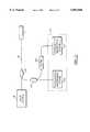
- FIG. 1is a longitudinal cross-sectional view of a wellbore which schematically illustrates the fiber optic intrinsic sensor of the invention interconnected to an electrically submersible pump;
- FIG. 2is a more detailed schematic block diagram of the fiber optic intrinsic sensor of FIG. 1;
- FIG. 3is a schematic bock diagram of optical signal processing equipment utilized to analyze optical signals provided by the fiber optic intrinsic sensor of FIGS. 1 and 2;
- FIG. 4is a schematic block diagram of a second embodiment of the fiber optic intrinsic sensor of FIG. 1;
- FIG. 5is a schematic block diagram of a third embodiment of the fiber optic intrinsic sensor of FIG. 1.
- the present inventionutilizes fiber optic sensors for measuring fluid pressure (static and dynamic), temperature, and vibration.
- the present inventionutilizes resonant structures, called Bragg gratings, that are disposed at multiple locations within the waveguiding core of an optical fiber.
- the intrinsic fiber optic sensor elements utilized in accordance with the inventionare disposed in a sensor 1 which is mounted in a mounting location, such as to the casing of an electrically submersible pump 2 within a wellbore 3 of an oil and/or gas well 5.
- a sensor 1which is mounted in a mounting location, such as to the casing of an electrically submersible pump 2 within a wellbore 3 of an oil and/or gas well 5.
- casing strings 9, 10, production tubing 12, and production packers 13Within the wellbore 3 are casing strings 9, 10, production tubing 12, and production packers 13.
- the optical sensor 1is interconnected by an optical fiber assembly 15 with optical signal processing equipment 18.
- the optical signal processing equipment 18is located above the surface 20 of the wellbore 3.
- the electrical submersible pump 2is interconnected by an electrical cable 22 to an electrical submersible pump power supply and controller 25, which is also located above the surface 20 of the wellbore 3.
- the optical fiber assembly 15includes an optical fiber 24 which is protected from mechanical damage by placing it inside a capillary tube 31 made of a high strength, rigid walled, corrosion-resistant material, such as stainless steel.
- the tube 31is attached by appropriate means, such as threads at 32, a weld, or other suitable method, to the structure 33 which it is monitoring, such as the casing of the ESP 2.
- the optical fiber 24extends from the surface 20 (FIG. 1) of the well and contains a light guiding core 35 which guides light along the fiber 24.
- Each Bragg grating 46, 47, 48is constructed so as to reflect a particular wavelength or frequency of light which is propagating along the core 35, back in the direction of the light source from which it was launched. Each of the particular frequencies is different from the other such that each Bragg grating 46, 47, 48 reflects a unique frequency.
- excitation lightmay be provided by a broadband light source 49, such as a light emitting diode (LED) located within the optical signal processing equipment 18.
- the Bragg gratings 46, 47, 48are used to implement the multi-parameter sensor of the invention, including a temperature sensor 53, an acceleration (vibration) sensor 52, and a pressure sensor 51, respectively.
- tubing delivery equipmentfor delivering the optical fiber 24 within the capillary tubing 31 down the borehole 3.
- the tubing delivery equipmentprovides for the delivery of the capillary tubing 31 and fiber 24 down the borehole 3, and for the delivery of optical signals between the optical signal processing equipment 18 and the fiber assembly 15, either directly or via interface equipment (not shown) as required.
- Fiber gratingsare well suited for use as sensor elements. When a fiber grating is illuminated, it reflects a narrow band of light at a specified wavelength. However, a measurand, such as strain induced by pressure or temperature, will induce a change in the fiber grating spacing, which changes the wavelength of the light it reflects. The value (magnitude) of the measurand is directly related to the wavelength reflected by the fiber grating and can be determined by detecting the wavelength of the reflected light.
- the optical signal processing equipment 18includes, at a minimum, the broadband source of light 49, such as the light emitting diode (LED), and appropriate equipment for delivery of signal light to the Bragg gratings 46, 47, 48 included within the core 35 of the optical fiber 24. Additionally, the optical signal processing equipment 18 includes appropriate optical signal analysis equipment 50 for analyzing the return signals from the Bragg gratings 46, 47, 48.
- the broadband source of light 49such as the light emitting diode (LED)
- LEDlight emitting diode
- FIG. 3shows an arrangement for monitoring the wavelength shifts produced by the Bragg grating sensors 46, 47, 48 to provide both static pressure and temperature monitoring along with high resolution dynamic sensing for acceleration (vibration) and dynamic pressure (acoustic) parameters.
- the fiber 24is coupled to the sensor 1 via the stainless steel capillary tube 31.
- the sensor 1, located at the distal end of optical fiber 24,contains the Bragg gratings 46, 47, and 48 each of which acts as a resonant reflector, and each of which operates as a sensor mounted as to respond in a manner described in greater detail below.
- Light from the broadband optical source 49is coupled to the fiber 24 via a coupler 222.
- This coupler 222directs light to the sensor assembly 1, and directs the reflected optical components from the Bragg grating sensors 46, 47, 48 to the optical signal processing equipment 18 including wavelength monitoring sub-systems, 224 and 226.
- One of the wavelength monitoring systems 224allows for the detection of wavelength shifts of the Bragg grating elements using an ⁇ absolute ⁇ approach for static parameter monitoring (e.g. pressure & temperature).
- the other wavelength monitoring system 226provides for detecting weak dynamically induced shifts for vibration and dynamic pressure monitoring.
- the returned optical componentsare directed into an optical wavelength analyzer 224, such as a scanning narrowband filter, which produces a measure of the Bragg wavelength of the signal light reflected by the Bragg gratings 46, 47, 48.
- an optical wavelength analyzer 224such as a scanning narrowband filter, which produces a measure of the Bragg wavelength of the signal light reflected by the Bragg gratings 46, 47, 48.
- Static pressurecan be deduced from the differential shift of the Bragg wavelengths produced by Bragg gratings 46 and 48, whereas the temperature is determined directly from a measure of the Bragg wavelength of Bragg grating 46.
- a portion of the returned optical componentsis split off, using a coupler 223, to an alternative wavelength discriminator 226 to thereby provide high resolution monitoring of wavelength shifts.
- a portion of the returned optical components from the gratingsare directed to a wavelength filter or router 225.
- This deviceseparates the optical signals produced by each Bragg grating by means of selective filtering. The pass-bands of this device are wide enough to ensure that under normal operating conditions (full temperature & pressure range), the optical signal produced by, for example grating 47 is always passed.
- the outputs of the routercan then be analyzed using a sensitive wavelength discriminators 226 to determine wavelength modulation effects due to vibration, dynamic pressure, or acoustic information.
- the separate gratings in the systemcan be analyzed individually.
- a wavelength division demultiplexercould be used to separate the wavelength components onto separate fibers which could then be each analyzed via separate high resolution wavelength discriminators.
- An example of the type of wavelength discriminators suitable for this purposeis the interferometric detection approach described in U.S. Pat. No. 5,361,130, the disclosure of which is incorporated herein by reference.
- optical signal processing equipment 18Although a specific embodiment of the optical signal processing equipment 18 is described above, other optical signal analysis techniques may be used with the present invention such as the necessary hardware and software to implement the optical signal diagnostic equipment disclosed in U.S. Pat. Nos. 4,996,419; 5,401,956; 5,426,297; and/or U.S. Pat. No. 5,493,390, the disclosures of which are incorporated herein by reference.
- Direct spectroscopyutilizing conventional dispersive elements such as line gratings, prisms, etc., and a linear array of photo detector elements or a CCD array;
- a tuneable filtersuch as, for example, a scanning Fabry-Perot filter, an acousto-optic filter such as the filter described in the above referenced U.S. Pat. No. 5,493,390, or fiber Bragg grating based filters; and
- the optical signal processing equipmentmay operate on a principle of wave-division multiplexing as described above wherein each Bragg grating sensor is utilized at a different passband or frequency band of interest.
- the present inventionmay utilize time-division multiplexing for obtaining signals from multiple independent sensors, or any other suitable means for analyzing signals returned from a plurality of Bragg grating sensors formed in a fiber optic sensor string.
- the senor 1includes three separate sensor elements formed therein.
- the sensor 1includes a pressure sensor 51, a vibration sensor 52, and a temperature sensor 53, as described above.
- the pressure sensor 51is constructed as follows.
- the optical fiber 24extends to a distal end 54 of the capillary tube 31.
- a cavity 55is formed by the presence of a rigid member 59 positioned within the capillary tube 31 and spaced from the distal end 54 of the capillary tube 31.
- the rigid member 59may be made of a corrosion resistant material such as stainless steel or beryllium copper.
- the rigid member 59is attached 58 to both the internal surfaces of the tube 31 and the surface of the optical fiber 24 by a suitable adhesion method such as utilizing an adhesive compound, mechanical attachment (shrink or pressure fit), welding of a metal coated fiber to a metallic rigid member, etc. Therefore, at the attachment point to the rigid member 59, the optical fiber is effectively isolated from pressure and vibration effects.
- the attachment pointacts as an effective reference point for pressure variations measured by the pressure sensor 51 of the invention.
- the cavity 55is located between the rigid member 59 and the distal end 54 of the capillary tube 31.
- a low bulk modulus material 60is placed within the cavity 55, and is also bonded 61 to the optical fiber 24 length within the cavity 55, for example, using an adhesive compound.
- the low bulk modulus material 60may be made of a polymer material, such as a polyurethane, e.g. URALITE 3140.
- the low bulk modulus material 60may also be bonded 61 to the internal surfaces of the tube 31.
- One of the Bragg gratings 48is located generally in the center of the cavity 55.
- the distal end 36 of fiber 24is terminated in an anti-reflective manner, so as to prevent interference with the reflected wavelengths from the Bragg gratings 46, 47 and 48.
- the distal end 36 of the fiber 24may be cleaved at an angle so that the end face is not perpendicular to the fiber axis.
- the distal end 36 of the fiber 24may be coated with a material that matches the index of refraction of the fiber, thus permitting light to exit the fiber without back reflection, and be subsequently disbursed in the index-matching material.
- a thin diaphragm 62is located over the end of the capillary tube 31 and the low bulk modulus material 60.
- the diaphragm 62is made of a high strength corrosion resistant material, such as stainless steel or beryllium copper. Such materials also should exhibit very low mechanical hysteresis.
- the diaphragm 62serves to protect the fiber 24 from mechanical and corrosive damage, and is attached 57 to the end of capillary tube 31 by appropriate means, such as welding, to a achieve a hermetic seal.
- the pressure to be sensedcauses the diaphragm 62 to deflect, compressing the low bulk modulus material 60, which in turn causes an axial compression of the Bragg grating 48 (with respect to the reference point in the rigid member 59).
- This axial strain in the Bragg grating 48causes a decrease in the grating spacing, thus changing the wavelength of light reflected back to the optical signal processing equipment 18, as described above.
- This change in wavelength seen at the optical signal processing equipment 18is directly related to the applied pressure on the diaphragm 62 (as sensed by the Bragg grating 48).
- the sensorfunctions as a pressure sensor, wherein a wavelength shift in light reflected by the Bragg grating 48 is proportional to applied pressure. The wavelength shift is detected by appropriate optical signal analysis equipment 50 located within the optical signal processing equipment 18.
- the vibration sensor 52is constructed as follows. Another resiliently deformable element 63 of low bulk modulus material is attached to the opposite side of the rigid member 59 from the previously mentioned low bulk modulus material 60. Although not required, the low bulk modulus material 63 may be attached to the inside of the capillary tube 31 to prevent vibration in directions other than along the common axis of the capillary tube 31 and fiber 24. The fiber 24 extends through and is attached to the element 63. Within the axial extent of the element 63 is located one of the Bragg gratings 47. Another rigid element 64, preferably of relatively high mass, is attached to the element 63.
- the rigid element of high mass (rigid mass) 64is utilized as a proof mass in the vibration (acceleration) sensor 52, and therefore is not attached to the inside of the capillary tube 31 to allow relative movement therebetween.
- the rigid mass 64is preferably made of a corrosion resistant material having a coefficient of thermal expansion that closely matches the coefficient of thermal expansion of the capillary tube 31 to prevent binding therebetween.
- the rigid mass 64may be coated with a low coefficient-of-friction coating 66, such as polytetra-fluorethyene (PTFE), to prevent adhesion to the inside wall of the capillary tube 31 or mechanical wear due to relative motion.
- PTFEpolytetra-fluorethyene
- the inside surface of the capillary tubemay be coated with a low coefficient-of-friction coating in the area of the rigid mass 64.
- the rigid mass 64may be attached to the fiber 24. At a minimum, the rigid mass 64 is attached to the element 63.
- the rigid mass 64is accelerated in the direction 65 as shown with respect to the rigid member 59, producing a force which acts to expand and compress the element 63.
- This expansion and compressionin turn causes an axial expansion and compression of the Bragg grating 47.
- the devicefunctions as an accelerometer, with the shift in wavelength of light reflected by the Bragg grating 47 being proportion to the applied acceleration.
- the rigid mass 64is separated from the internal surface of the capillary tube 31 by an annular space 68, which permits the rigid mass 64 to move freely with respect to the capillary tube 31.
- the annular space 68also helps prevent binding between the capillary tube 31 and the rigid mass 64 due to differences in thermal expansion therebetween.
- the length of the fiber 24 in a region 67 immediately above the rigid mass 64forms a strain relief consisting, for example, of a loop of excess length of fiber, or other known means, to avoid transmitting the strain created on the Bragg grating 47 by acceleration of rigid mass 64 to Bragg grating 46, which is intended to sense only temperature, as described below.
- the temperature sensor 53is constructed as follows.
- the Bragg grating 46is located in a passage through a rigid element 71.
- This rigid element 71effectively isolates the Bragg grating 46 from strain due to external pressure and vibration. Since the Bragg grating 46 is effectively isolated from the effects of strain on grating spacing associated with pressure and vibration, the Bragg grating 46 responds only to the effects of temperature, and acts as a temperature sensor only.
- the acceleration sensor Bragg grating 47, and the pressure sensor Bragg grating 48are also sensitive to both temperature and strain, the output of temperature sensor Bragg grating 46 can be used to cancel the effects of temperature in the Bragg gratings 47 and 48.
- the acceleration and pressure measurementsmay be temperature compensated in the optical signal processing equipment 18.
- these multiple temperature sensors 53, 53amay be used to provide a temperature gradient or profile of the environment.
- linear temperature compensationalone may not be sufficient to produce a linear sensor. Therefore the device may be further characterized over temperature, allowing a correction of output for temperature by means of curve fitting, look-up table, or other suitable means.
- the inventionis described above as utilizing a low-bulk modulus material 60 in the cavity 55 formed between the rigid member 59 and the distal end 57 of the capillary tube 31.
- the fiber 24 containing the pressure sensing Bragg grating 48is suspended between the rigid member 59 and the diaphragm 62. This arrangement provides for a high degree of sensitivity to changes in pressure as reflected by movement of the diaphragm 62.
- the optical fiber 24extends to the distal end 57 of the capillary tube 31.
- the low bulk modulus material 60(FIG. 2) is eliminated from the cavity 55, such that the cavity 55 formed by the diaphragm 62 and the rigid member 59 is empty, except for the length of optical fiber 24 containing the pressure sensing Bragg grating 48.
- the fiber 24, which is rigidly attached to the rigid member 59 as described above,is also rigidly attached at an attachment point 69 to the diaphragm 62, for example by a high strength adhesive, a weld, or other suitable adhesion method.
- the Bragg grating 48is located along the cavity axis as shown.
- the distal end 36 of the fiber 24is terminated in an anti-reflective manner.
- the diaphragm 62is attached to the end of the capillary tube 31 by appropriate means, such as welding, to achieve a hermetic seal.
- the pressure to be sensedcauses the diaphragm 62 to deflect an amount dependent on the magnitude of the pressure change and the diaphragm material, thickness and diameter. Deflection of the diaphragm 62 causes a direct change in the strain-state of the fiber 24 held between the rigid member 59 and the diaphragm 62, thereby altering the Bragg resonance wavelength of the Bragg grating 58.
- the action of compressing the Bragg grating sensor 48can lead to a buckling effect in the fiber 24, between the rigid member 59 and the diaphragm 62, if unsupported.
- the fiber 24 held between the rigid member 59 and the diaphragm 62is mounted under an initial axial tension (bias tension).
- This bias tension in the fiber 24results in an offset of the resonance of the Bragg grating 58, thus changing the wavelength of light reflected back to the proximal end of the fiber.
- Changes in the pressure field then applied to diaphragm 62thus results in a reduction in the bias tension in the fiber 24 and a shift in the Bragg wavelength of the Bragg grating sensor 58, which as previously discussed can be detected at the proximal end of the fiber by appropriate and well known optical/electronic means, such as using a scanning optical filter, miniature spectrometer, or other approach well known in the art.
- the pressure sensor 52may utilize a thin wall, rigid tube 70 in the cavity 55 formed between the rigid member 59 and the distal end 36 of the capillary tube 31.
- the distal end 36 of the fiber 24may be bonded to the diaphragm 62 at an attachment point 69 such that movement of the diaphragm 62 is directly translated to the optical fiber 24 and the Bragg grating 48.
- the rigid member 59being bonded to both the internal surfaces of the tube 31 and the surface of the optical fiber 24, prevents the strain placed on the fiber 24 by the diaphragm 62 from being transmitted to the remainder of the fiber 24.
- the fiber 24may be placed under an initial bias tension in the third embodiment of FIG. 5.
Landscapes
- Physics & Mathematics (AREA)
- General Physics & Mathematics (AREA)
- Testing Or Calibration Of Command Recording Devices (AREA)
- Measuring Fluid Pressure (AREA)
- Optical Transform (AREA)
- Length Measuring Devices By Optical Means (AREA)
Abstract
Description
Claims (36)
Priority Applications (7)
| Application Number | Priority Date | Filing Date | Title |
|---|---|---|---|
| US08/786,704US5892860A (en) | 1997-01-21 | 1997-01-21 | Multi-parameter fiber optic sensor for use in harsh environments |
| EP98902822AEP0954743B1 (en) | 1997-01-21 | 1998-01-20 | Multiparameter fiber optic sensor for use in harsh environments |
| CA002288957ACA2288957C (en) | 1997-01-21 | 1998-01-20 | Multiparameter fiber optic sensor for use in harsh environments |
| PCT/US1998/001046WO1998031987A1 (en) | 1997-01-21 | 1998-01-20 | Multiparameter fiber optic sensor for use in harsh environments |
| AU59623/98AAU5962398A (en) | 1997-01-21 | 1998-01-20 | Multiparameter fiber optic sensor for use in harsh environments |
| DE69829647TDE69829647D1 (en) | 1997-01-21 | 1998-01-20 | FIBER OPTIC MULTI-PARAMETER SENSOR FOR USE IN HARSH ENVIRONMENTS |
| NO19993551ANO328203B1 (en) | 1997-01-21 | 1999-07-20 | Fiber optic multi-parameter sensor for use in rough environment. |
Applications Claiming Priority (1)
| Application Number | Priority Date | Filing Date | Title |
|---|---|---|---|
| US08/786,704US5892860A (en) | 1997-01-21 | 1997-01-21 | Multi-parameter fiber optic sensor for use in harsh environments |
Publications (1)
| Publication Number | Publication Date |
|---|---|
| US5892860Atrue US5892860A (en) | 1999-04-06 |
Family
ID=25139364
Family Applications (1)
| Application Number | Title | Priority Date | Filing Date |
|---|---|---|---|
| US08/786,704Expired - LifetimeUS5892860A (en) | 1997-01-21 | 1997-01-21 | Multi-parameter fiber optic sensor for use in harsh environments |
Country Status (7)
| Country | Link |
|---|---|
| US (1) | US5892860A (en) |
| EP (1) | EP0954743B1 (en) |
| AU (1) | AU5962398A (en) |
| CA (1) | CA2288957C (en) |
| DE (1) | DE69829647D1 (en) |
| NO (1) | NO328203B1 (en) |
| WO (1) | WO1998031987A1 (en) |
Cited By (135)
| Publication number | Priority date | Publication date | Assignee | Title |
|---|---|---|---|---|
| WO2000072025A1 (en)* | 1999-05-21 | 2000-11-30 | Siemens Aktiengesellschaft | Bragg grating device for measuring an acceleration |
| US6175108B1 (en) | 1998-01-30 | 2001-01-16 | Cidra Corporation | Accelerometer featuring fiber optic bragg grating sensor for providing multiplexed multi-axis acceleration sensing |
| US6233746B1 (en)* | 1999-03-22 | 2001-05-22 | Halliburton Energy Services, Inc. | Multiplexed fiber optic transducer for use in a well and method |
| US6274863B1 (en) | 1999-07-23 | 2001-08-14 | Cidra Corporation | Selective aperture arrays for seismic monitoring |
| US6281976B1 (en)* | 1997-04-09 | 2001-08-28 | The Texas A&M University System | Fiber optic fiber Fabry-Perot interferometer diaphragm sensor and method of measurement |
| US20020007948A1 (en)* | 2000-01-05 | 2002-01-24 | Bayne Christian F. | Method of providing hydraulic/fiber conduits adjacent bottom hole assemblies for multi-step completions |
| US6341526B1 (en) | 1998-07-29 | 2002-01-29 | Interscience, Inc. | Micromachined diffractive pressure sensor system |
| US6478091B1 (en)* | 2000-05-04 | 2002-11-12 | Halliburton Energy Services, Inc. | Expandable liner and associated methods of regulating fluid flow in a well |
| US20020172446A1 (en)* | 1998-12-04 | 2002-11-21 | Fernald Mark R. | Pressure-isolated Bragg grating temperature sensor |
| US6575033B1 (en)* | 1999-10-01 | 2003-06-10 | Weatherford/Lamb, Inc. | Highly sensitive accelerometer |
| US6580511B1 (en) | 1997-10-28 | 2003-06-17 | Reliance Electric Technologies, Llc | System for monitoring sealing wear |
| US6671055B1 (en) | 2000-04-13 | 2003-12-30 | Luna Innovations, Inc. | Interferometric sensors utilizing bulk sensing mediums extrinsic to the input/output optical fiber |
| US20040008934A1 (en)* | 2000-09-26 | 2004-01-15 | Yoshihiro Takiguchi | Optical fiber connector, wavelength varying device, pressure sensor, acceleration sensor, and optical device |
| WO2004007893A2 (en) | 2002-07-11 | 2004-01-22 | Weatherford/Lamb Inc. | Improving collapse resistance of tubing |
| US20040016295A1 (en)* | 2002-07-23 | 2004-01-29 | Skinner Neal G. | Subterranean well pressure and temperature measurement |
| US20040036005A1 (en)* | 2000-08-25 | 2004-02-26 | Jirapong Lim | Monitoring optically powered actuators |
| US20040047534A1 (en)* | 2002-09-09 | 2004-03-11 | Shah Vimal V. | Downhole sensing with fiber in exterior annulus |
| US20040060695A1 (en)* | 2000-05-05 | 2004-04-01 | Halliburton Energy Services, Inc. | Expandable well screen |
| US20040060697A1 (en)* | 2002-09-27 | 2004-04-01 | Tilton Frederick T. | Smart cementing systems |
| US20040065439A1 (en)* | 1997-05-02 | 2004-04-08 | Baker Hughes Incorporated | Wellbores utilizing fiber optic-based sensors and operating devices |
| US6721470B2 (en) | 1999-12-23 | 2004-04-13 | Siemens Aktiengesellschaft | Optical measurement device in a pressed-in conductor bar in an electrical machine |
| US20040084189A1 (en)* | 2002-11-05 | 2004-05-06 | Hosie David G. | Instrumentation for a downhole deployment valve |
| US20040089074A1 (en)* | 2001-01-31 | 2004-05-13 | Jean-Bernard Avisse | Pressure sensor and rocket engine incoporating same |
| US20040108118A1 (en)* | 2002-09-26 | 2004-06-10 | Williams Glynn R. | Fibre optic well control system |
| US20040112595A1 (en)* | 2002-11-05 | 2004-06-17 | F.X. Bostick | Permanent downhole deployment of optical sensors |
| US20040139791A1 (en)* | 2003-01-21 | 2004-07-22 | Johansen Espen S. | Non-intrusive multiphase flow meter |
| US20040140092A1 (en)* | 2003-01-21 | 2004-07-22 | Robison Clark E. | Linear displacement measurement method and apparatus |
| GB2397885A (en)* | 2003-01-21 | 2004-08-04 | Weatherford Lamb | Fibre optic acoustic sensor for monitoring well logging equipment |
| US20040202401A1 (en)* | 2002-10-06 | 2004-10-14 | Arne Berg | High pressure and high temperature acoustic sensor |
| US20040231429A1 (en)* | 2003-05-19 | 2004-11-25 | Niezgorski Richard M. | Housing on the exterior of a well casing for optical fiber sensors |
| WO2004104372A1 (en) | 2003-05-19 | 2004-12-02 | Weatherford/Lamb, Inc. | Well integrity monitoring system |
| US6828547B2 (en)* | 1997-05-02 | 2004-12-07 | Sensor Highway Limited | Wellbores utilizing fiber optic-based sensors and operating devices |
| US20040251032A1 (en)* | 2002-11-05 | 2004-12-16 | Weatherford/Lamb, Inc. | Apparatus and methods for utilizing a downhole deployment valve |
| US20050039544A1 (en)* | 2003-08-22 | 2005-02-24 | Jones Richard T. | Flow meter using an expanded tube section and sensitive differential pressure measurement |
| US20050056419A1 (en)* | 2002-11-05 | 2005-03-17 | Hosie David G. | Apparatus for wellbore communication |
| US6891621B2 (en) | 2001-02-06 | 2005-05-10 | Weatherford/Lamb, Inc. | Highly sensitive cross axis accelerometer |
| US20050097955A1 (en)* | 1999-10-01 | 2005-05-12 | Arne Berg | Highly sensitive accelerometer |
| US20050109518A1 (en)* | 2003-11-18 | 2005-05-26 | Blacklaw David W. | Fiber optic deployment apparatus and method |
| US6915686B2 (en) | 2003-02-11 | 2005-07-12 | Optoplan A.S. | Downhole sub for instrumentation |
| US20050206526A1 (en)* | 2004-03-17 | 2005-09-22 | Yoshihiro Ozawa | Road-ice detecting sensor, method for installing same, and road-ice detecting method |
| WO2005033465A3 (en)* | 2003-10-03 | 2005-09-29 | Sabeus Photonics Inc | Downhole fiber optic acoustic sand detector |
| US20050224229A1 (en)* | 2004-04-08 | 2005-10-13 | Wood Group Logging Services, Inc. | Methods of monitoring downhole conditions |
| US20050230118A1 (en)* | 2002-10-11 | 2005-10-20 | Weatherford/Lamb, Inc. | Apparatus and methods for utilizing a downhole deployment valve |
| US20050251362A1 (en)* | 2004-06-05 | 2005-11-10 | Ollre Albert G | System and method for determining pump underperformance |
| US20050274194A1 (en)* | 2004-06-15 | 2005-12-15 | Skinner Neal G | Fiber optic differential pressure sensor |
| US6978832B2 (en) | 2002-09-09 | 2005-12-27 | Halliburton Energy Services, Inc. | Downhole sensing with fiber in the formation |
| US20060008196A1 (en)* | 2002-09-30 | 2006-01-12 | Commissariat A L'energie Atomique | Bragg grating pressure sensor |
| US20060137456A1 (en)* | 2004-12-27 | 2006-06-29 | Samhita Dasgupta | Static and dynamic pressure sensor |
| US20060283255A1 (en)* | 2004-12-27 | 2006-12-21 | General Electric Company | High-temperature pressure sensor |
| US7159653B2 (en) | 2003-02-27 | 2007-01-09 | Weatherford/Lamb, Inc. | Spacer sub |
| US7168311B2 (en)* | 2001-09-20 | 2007-01-30 | Baker Hughes Incorporated | Fiber optic monitoring of flow inside and outside a tube downhole |
| US7208855B1 (en) | 2004-03-12 | 2007-04-24 | Wood Group Esp, Inc. | Fiber-optic cable as integral part of a submersible motor system |
| US20070169933A1 (en)* | 2006-01-11 | 2007-07-26 | Besst, Inc., | Sensor assembly for determining fluid properties in a subsurface well |
| US7255173B2 (en) | 2002-11-05 | 2007-08-14 | Weatherford/Lamb, Inc. | Instrumentation for a downhole deployment valve |
| US20070234789A1 (en)* | 2006-04-05 | 2007-10-11 | Gerard Glasbergen | Fluid distribution determination and optimization with real time temperature measurement |
| US20070289779A1 (en)* | 2006-03-30 | 2007-12-20 | Schlumberger Technology Corporation | Providing a sensor array |
| US20080089636A1 (en)* | 2006-08-30 | 2008-04-17 | Macdougall Trevor | Array temperature sensing method and system |
| US20080095612A1 (en)* | 2004-04-27 | 2008-04-24 | Paul Girbig | Method And Regulation System For Monitoring A Compressor Of A Gas Turbine In Particular |
| US7396216B2 (en)* | 2002-04-23 | 2008-07-08 | Halliburton Energy Services, Inc. | Submersible pump assembly for removing a production inhibiting fluid from a well and method for use of same |
| US20080181553A1 (en)* | 1997-10-28 | 2008-07-31 | Reliance Electric Technologies, Llc | System for monitoring sealing wear |
| US20080181555A1 (en)* | 2005-03-16 | 2008-07-31 | Philip Head | Well Bore Sensing |
| US7431082B2 (en) | 2005-08-19 | 2008-10-07 | Baker Hughes Incorporated | Retaining lines in bypass groove on downhole equipment |
| US20080264182A1 (en)* | 2003-08-22 | 2008-10-30 | Jones Richard T | Flow meter using sensitive differential pressure measurement |
| US20080271926A1 (en)* | 2007-05-04 | 2008-11-06 | Baker Hughes Incorporated | Mounting system for a fiber optic cable at a downhole tool |
| US20090123109A1 (en)* | 2007-11-09 | 2009-05-14 | Lxdata Inc | Temperature sensor using an optical fiber |
| US7551288B1 (en) | 1997-10-28 | 2009-06-23 | Rockwell Automation Technologies, Inc. | System for monitoring bearing wear |
| US20090188665A1 (en)* | 1997-05-02 | 2009-07-30 | Baker Hughes Incorporated | Monitoring of Downhole Parameters and Tools Utilizing Fiber Optics |
| US20090199630A1 (en)* | 2008-02-12 | 2009-08-13 | Baker Hughes Incorporated | Fiber optic sensor system using white light interferometery |
| US20100066315A1 (en)* | 2008-09-12 | 2010-03-18 | Siemens Power Generation, Inc. | Method and System for Monitoring the Condition of Generator End Windings |
| US20100106421A1 (en)* | 2008-10-22 | 2010-04-29 | Baker Hughes Incorporated | Distributed measurement of mud temperature |
| US7740064B2 (en) | 2006-05-24 | 2010-06-22 | Baker Hughes Incorporated | System, method, and apparatus for downhole submersible pump having fiber optic communications |
| US20100207019A1 (en)* | 2009-02-17 | 2010-08-19 | Schlumberger Technology Corporation | Optical monitoring of fluid flow |
| US20110002795A1 (en)* | 2009-07-01 | 2011-01-06 | Baker Hughes Incorporated | System to Measure Vibrations Using Fiber Optic Sensors |
| US20110088462A1 (en)* | 2009-10-21 | 2011-04-21 | Halliburton Energy Services, Inc. | Downhole monitoring with distributed acoustic/vibration, strain and/or density sensing |
| US20110224687A1 (en)* | 2005-12-30 | 2011-09-15 | Intuitive Surgical Operations, Inc. | Robotic surgery system including position sensors using fiber bragg gratings |
| US20110229071A1 (en)* | 2009-04-22 | 2011-09-22 | Lxdata Inc. | Pressure sensor arrangement using an optical fiber and methodologies for performing an analysis of a subterranean formation |
| US8186428B2 (en)* | 2007-04-03 | 2012-05-29 | Baker Hughes Incorporated | Fiber support arrangement for a downhole tool and method |
| WO2012074664A3 (en)* | 2010-12-03 | 2012-08-16 | Baker Hughes Incorporated | Modeling an interpretation of real time compaction modeling data from multi-section monitoring system |
| US8245780B2 (en) | 2009-02-09 | 2012-08-21 | Shell Oil Company | Method of detecting fluid in-flows downhole |
| WO2012109502A3 (en)* | 2011-02-10 | 2013-04-25 | Siemens Energy, Inc. | Vibration sensor |
| WO2013085672A1 (en)* | 2011-12-07 | 2013-06-13 | Baker Hughes Incorporated | Fiber optic measurement of parameters for downhole pump diffuser section |
| US8505625B2 (en) | 2010-06-16 | 2013-08-13 | Halliburton Energy Services, Inc. | Controlling well operations based on monitored parameters of cement health |
| US8584519B2 (en) | 2010-07-19 | 2013-11-19 | Halliburton Energy Services, Inc. | Communication through an enclosure of a line |
| US8636063B2 (en) | 2011-02-16 | 2014-01-28 | Halliburton Energy Services, Inc. | Cement slurry monitoring |
| US8662165B2 (en) | 2010-07-06 | 2014-03-04 | Baker Hughes Incorporated | Fiber support arrangement and method |
| WO2014144206A1 (en) | 2013-03-15 | 2014-09-18 | Weatherford/Lamb, Inc. | Direct slurry weight sensor for well operation mixing process |
| US8879067B2 (en) | 2010-09-01 | 2014-11-04 | Lake Shore Cryotronics, Inc. | Wavelength dependent optical force sensing |
| US20140326466A1 (en)* | 2013-05-02 | 2014-11-06 | Baker Hughes Incorporated | Systems and Methods for Providing Fiber Optics in Downhole Equipment |
| US8924158B2 (en) | 2010-08-09 | 2014-12-30 | Schlumberger Technology Corporation | Seismic acquisition system including a distributed sensor having an optical fiber |
| US9060678B2 (en) | 2006-06-13 | 2015-06-23 | Intuitive Surgical Operations, Inc. | Minimally invasive surgical system |
| US9075155B2 (en) | 2011-04-08 | 2015-07-07 | Halliburton Energy Services, Inc. | Optical fiber based downhole seismic sensor systems and methods |
| US9127532B2 (en) | 2011-09-07 | 2015-09-08 | Halliburton Energy Services, Inc. | Optical casing collar locator systems and methods |
| US9127531B2 (en) | 2011-09-07 | 2015-09-08 | Halliburton Energy Services, Inc. | Optical casing collar locator systems and methods |
| US20150268216A1 (en)* | 2014-03-24 | 2015-09-24 | Sandia Corporation | Sensor system that uses embedded optical fibers |
| US9194973B2 (en) | 2010-12-03 | 2015-11-24 | Baker Hughes Incorporated | Self adaptive two dimensional filter for distributed sensing data |
| US9239406B2 (en) | 2012-12-18 | 2016-01-19 | Halliburton Energy Services, Inc. | Downhole treatment monitoring systems and methods using ion selective fiber sensors |
| US9297767B2 (en) | 2011-10-05 | 2016-03-29 | Halliburton Energy Services, Inc. | Downhole species selective optical fiber sensor systems and methods |
| US20160154142A1 (en)* | 2013-08-02 | 2016-06-02 | Halliburton Energy Services, Inc. | Acoustic sensor metadata dubbing channel |
| US9387048B2 (en) | 2011-10-14 | 2016-07-12 | Intuitive Surgical Operations, Inc. | Catheter sensor systems |
| US9388686B2 (en) | 2010-01-13 | 2016-07-12 | Halliburton Energy Services, Inc. | Maximizing hydrocarbon production while controlling phase behavior or precipitation of reservoir impairing liquids or solids |
| US20160223389A1 (en)* | 2013-09-13 | 2016-08-04 | Silixa Ltd. | Non-isotropic acoustic cable |
| US9452276B2 (en) | 2011-10-14 | 2016-09-27 | Intuitive Surgical Operations, Inc. | Catheter with removable vision probe |
| US9557239B2 (en) | 2010-12-03 | 2017-01-31 | Baker Hughes Incorporated | Determination of strain components for different deformation modes using a filter |
| US9624763B2 (en) | 2014-09-29 | 2017-04-18 | Baker Hughes Incorporated | Downhole health monitoring system and method |
| US9757149B2 (en) | 2006-06-13 | 2017-09-12 | Intuitive Surgical Operations, Inc. | Surgical system entry guide |
| US9817019B2 (en) | 2013-11-13 | 2017-11-14 | Intuitive Surgical Operations, Inc. | Integrated fiber bragg grating accelerometer in a surgical instrument |
| US9823373B2 (en) | 2012-11-08 | 2017-11-21 | Halliburton Energy Services, Inc. | Acoustic telemetry with distributed acoustic sensing system |
| US9897497B2 (en) | 2014-03-20 | 2018-02-20 | Halliburton Energy Services, Inc. | Temperature-compensated strain-based transducer operating on differential measurements |
| US9962066B2 (en) | 2005-12-30 | 2018-05-08 | Intuitive Surgical Operations, Inc. | Methods and apparatus to shape flexible entry guides for minimally invasive surgery |
| US10060250B2 (en) | 2012-03-13 | 2018-08-28 | Halliburton Energy Services, Inc. | Downhole systems and methods for water source determination |
| US10238837B2 (en) | 2011-10-14 | 2019-03-26 | Intuitive Surgical Operations, Inc. | Catheters with control modes for interchangeable probes |
| US10408694B2 (en)* | 2016-06-07 | 2019-09-10 | Halliburton Energy Services, Inc. | Method to compensate measurement error of fiber Bragg grating sensor caused by hydrogen darkening |
| US10634553B1 (en) | 2019-01-30 | 2020-04-28 | Saudi Arabian Oil Company | Hybrid distributed acoustic testing |
| US10682070B2 (en) | 2011-10-14 | 2020-06-16 | Intuitive Surgical Operations, Inc. | Electromagnetic sensor with probe and guide sensing elements |
| US10880007B1 (en) | 2019-08-15 | 2020-12-29 | Saudi Arabian Oil Company | Simultaneous distributed temperature and vibration sensing using multimode optical fiber |
| US10942198B2 (en)* | 2018-02-20 | 2021-03-09 | General Electric Company | MEMS accelerometer anti-reflective and reflector coatings |
| US10962408B2 (en) | 2019-03-07 | 2021-03-30 | Saudi Arabian Oil Company | Quasi-fundamental-mode operated multimode fiber for distributed acoustic sensing |
| WO2021137872A1 (en)* | 2020-01-03 | 2021-07-08 | Halliburton Energy Services, Inc. | Ald-thin layer coating applications for sensing telemetry |
| CN113325464A (en)* | 2021-05-24 | 2021-08-31 | 西安石油大学 | Grid-mesh type fiber bragg grating acceleration seismic detector |
| US20210348501A1 (en)* | 2018-09-03 | 2021-11-11 | Ziebel As | Apparatus for obtaining wellbore pressure measurements |
| US11339636B2 (en) | 2020-05-04 | 2022-05-24 | Saudi Arabian Oil Company | Determining the integrity of an isolated zone in a wellbore |
| US11519767B2 (en) | 2020-09-08 | 2022-12-06 | Saudi Arabian Oil Company | Determining fluid parameters |
| US11530597B2 (en) | 2021-02-18 | 2022-12-20 | Saudi Arabian Oil Company | Downhole wireless communication |
| US11571264B2 (en) | 2007-12-18 | 2023-02-07 | Intuitive Surgical Operations, Inc. | Force sensor temperature compensation |
| US11603756B2 (en) | 2021-03-03 | 2023-03-14 | Saudi Arabian Oil Company | Downhole wireless communication |
| US11619114B2 (en) | 2021-04-15 | 2023-04-04 | Saudi Arabian Oil Company | Entering a lateral branch of a wellbore with an assembly |
| US11644351B2 (en) | 2021-03-19 | 2023-05-09 | Saudi Arabian Oil Company | Multiphase flow and salinity meter with dual opposite handed helical resonators |
| US11650111B2 (en) | 2007-12-18 | 2023-05-16 | Intuitive Surgical Operations, Inc. | Ribbed force sensor |
| US11913464B2 (en) | 2021-04-15 | 2024-02-27 | Saudi Arabian Oil Company | Lubricating an electric submersible pump |
| US11920469B2 (en) | 2020-09-08 | 2024-03-05 | Saudi Arabian Oil Company | Determining fluid parameters |
| US11994016B2 (en) | 2021-12-09 | 2024-05-28 | Saudi Arabian Oil Company | Downhole phase separation in deviated wells |
| US12019200B2 (en) | 2019-03-12 | 2024-06-25 | Saudi Arabian Oil Company | Downhole monitoring using few-mode optical fiber based distributed acoustic sensing |
| US12085687B2 (en) | 2022-01-10 | 2024-09-10 | Saudi Arabian Oil Company | Model-constrained multi-phase virtual flow metering and forecasting with machine learning |
| US12239393B2 (en) | 2020-05-18 | 2025-03-04 | Intuitive Surgical Operations, Inc. | Hard stop that produces a reactive moment upon engagement for cantilever-based force sensing |
| US12419713B2 (en) | 2018-11-15 | 2025-09-23 | Intuitive Surgical Operations, Inc. | Surgical instrument with sensor aligned cable guide |
Families Citing this family (18)
| Publication number | Priority date | Publication date | Assignee | Title |
|---|---|---|---|---|
| US6218661B1 (en) | 1996-09-09 | 2001-04-17 | Schlumberger Technology Corporation | Methods and apparatus for mechanically enhancing the sensitivity of transversely loaded fiber optic sensors |
| GB2326471B (en)* | 1997-06-19 | 2001-05-30 | British Aerospace | A strain isolated optical fibre bragg grating sensor |
| GB9813095D0 (en)* | 1998-06-18 | 1998-08-19 | Secr Defence | Temperature sensing apparatus |
| DE69942749D1 (en) | 1998-12-04 | 2010-10-21 | Cidra Corp | VOLTAGE INSULATED TEMPERATURE SENSOR WITH BRAGG GRILLE |
| AU778263B2 (en)* | 1998-12-04 | 2004-11-25 | Cidra Corporation | Strain-isolated optical temperature sensor |
| US6278811B1 (en) | 1998-12-04 | 2001-08-21 | Arthur D. Hay | Fiber optic bragg grating pressure sensor |
| JP4615726B2 (en)* | 1998-12-04 | 2011-01-19 | ウェザーフォード/ラム インコーポレーテッド | Bragg grating pressure sensor |
| DE19939583A1 (en)* | 1999-02-24 | 2000-09-14 | Siemens Ag | Bragg grating device to measure mechanical force, e.g. for vibration sensor |
| US6246048B1 (en) | 1999-05-18 | 2001-06-12 | Schlumberger Technology Corporation | Methods and apparatus for mechanically enhancing the sensitivity of longitudinally loaded fiber optic sensors |
| KR100760510B1 (en)* | 2006-05-26 | 2007-09-20 | 한국과학기술연구원 | Abnormality Detection Device of Rotating Body |
| GB2450157B (en)* | 2007-06-15 | 2011-12-21 | Baker Hughes Inc | System for determining an initial direction of rotation of an electrical submersible pump |
| SA08290691B1 (en) | 2007-10-31 | 2012-02-22 | شل انترناشيونال ريسيرش ماتشابيج بى . فى | Pressure Sensor Assembly and Method of Using the Assembly |
| GB2457934A (en)* | 2008-02-29 | 2009-09-02 | Vetco Gray Controls Ltd | Multidrop communications system using wavelength division multiplexing |
| AU2012272590B2 (en)* | 2011-06-24 | 2016-01-28 | Schlumberger Technology B.V. | Fiber-optic monitoring cable |
| TWI494546B (en)* | 2012-02-23 | 2015-08-01 | Univ Nat United | The manufacturing method and the measuring configration of a novel air-gap fabry-perot fiber interferometer sensor |
| WO2015020674A1 (en)* | 2013-08-09 | 2015-02-12 | Halliburton Energy Services, Inc. | Improved optical fiber feedthrough incorporating fiber bragg grating |
| US9702243B2 (en) | 2013-10-04 | 2017-07-11 | Baker Hughes Incorporated | Systems and methods for monitoring temperature using a magnetostrictive probe |
| WO2017150476A1 (en) | 2016-03-01 | 2017-09-08 | 株式会社シミウス | Optical fiber sensor |
Citations (19)
| Publication number | Priority date | Publication date | Assignee | Title |
|---|---|---|---|---|
| EP0210372A2 (en)* | 1985-05-31 | 1987-02-04 | Sumitomo Electric Industries Limited | Optical deformation sensor |
| EP0227556A1 (en)* | 1985-12-24 | 1987-07-01 | Schlumberger Industries | Optical sensor for physical magnitudes |
| US4900937A (en)* | 1988-10-20 | 1990-02-13 | Bicron Corporation | Well logging detector with decoupling optical interface |
| EP0404242A1 (en)* | 1989-06-23 | 1990-12-27 | AGIP S.p.A. | Method and device based on fibre-optic interferometer sensors, for analyzing the dynamic deformation of a structure or its components |
| US5042898A (en)* | 1989-12-26 | 1991-08-27 | United Technologies Corporation | Incorporated Bragg filter temperature compensated optical waveguide device |
| US5163321A (en)* | 1989-10-17 | 1992-11-17 | Baroid Technology, Inc. | Borehole pressure and temperature measurement system |
| US5308973A (en)* | 1990-11-22 | 1994-05-03 | Hilti Aktiengesellschaft | Method and device for the measurement of force by a fiber optics system by evaluating phase shift of light waves |
| US5315110A (en)* | 1993-06-29 | 1994-05-24 | Abb Vetco Gray Inc. | Metal cup pressure transducer with a support having a plurality of thermal expansion coefficients |
| US5351324A (en)* | 1993-09-10 | 1994-09-27 | The Regents Of The University Of California, Office Of Technology Transfer | Fiber optic security seal including plural Bragg gratings |
| US5357806A (en)* | 1993-05-03 | 1994-10-25 | Halliburton Company | Capacitive differential pressure sensor and method of measuring differential pressure at an oil or gas well |
| US5363463A (en)* | 1982-08-06 | 1994-11-08 | Kleinerman Marcos Y | Remote sensing of physical variables with fiber optic systems |
| US5399854A (en)* | 1994-03-08 | 1995-03-21 | United Technologies Corporation | Embedded optical sensor capable of strain and temperature measurement using a single diffraction grating |
| US5401956A (en)* | 1993-09-29 | 1995-03-28 | United Technologies Corporation | Diagnostic system for fiber grating sensors |
| US5444803A (en)* | 1993-04-24 | 1995-08-22 | Agency Of Defense Development | Fiber-optic devices and sensors using fiber grating |
| US5452087A (en)* | 1993-11-04 | 1995-09-19 | The Texas A & M University System | Method and apparatus for measuring pressure with embedded non-intrusive fiber optics |
| US5485745A (en)* | 1991-05-20 | 1996-01-23 | Halliburton Company | Modular downhole inspection system for coiled tubing |
| US5495237A (en)* | 1992-12-07 | 1996-02-27 | Akishima Laboratories (Mitsui Zosen) Inc. | Measuring tool for collecting down hole information and metering valve for producing mud-pulse used in the same |
| US5499533A (en)* | 1992-08-26 | 1996-03-19 | Miller; Mark | Downhole pressure gauge converter |
| US5548116A (en)* | 1994-03-01 | 1996-08-20 | Optoscint, Inc. | Long life oil well logging assembly |
- 1997
- 1997-01-21USUS08/786,704patent/US5892860A/ennot_activeExpired - Lifetime
- 1998
- 1998-01-20WOPCT/US1998/001046patent/WO1998031987A1/enactiveIP Right Grant
- 1998-01-20AUAU59623/98Apatent/AU5962398A/ennot_activeAbandoned
- 1998-01-20DEDE69829647Tpatent/DE69829647D1/ennot_activeExpired - Lifetime
- 1998-01-20EPEP98902822Apatent/EP0954743B1/ennot_activeExpired - Lifetime
- 1998-01-20CACA002288957Apatent/CA2288957C/ennot_activeExpired - Fee Related
- 1999
- 1999-07-20NONO19993551Apatent/NO328203B1/ennot_activeIP Right Cessation
Patent Citations (19)
| Publication number | Priority date | Publication date | Assignee | Title |
|---|---|---|---|---|
| US5363463A (en)* | 1982-08-06 | 1994-11-08 | Kleinerman Marcos Y | Remote sensing of physical variables with fiber optic systems |
| EP0210372A2 (en)* | 1985-05-31 | 1987-02-04 | Sumitomo Electric Industries Limited | Optical deformation sensor |
| EP0227556A1 (en)* | 1985-12-24 | 1987-07-01 | Schlumberger Industries | Optical sensor for physical magnitudes |
| US4900937A (en)* | 1988-10-20 | 1990-02-13 | Bicron Corporation | Well logging detector with decoupling optical interface |
| EP0404242A1 (en)* | 1989-06-23 | 1990-12-27 | AGIP S.p.A. | Method and device based on fibre-optic interferometer sensors, for analyzing the dynamic deformation of a structure or its components |
| US5163321A (en)* | 1989-10-17 | 1992-11-17 | Baroid Technology, Inc. | Borehole pressure and temperature measurement system |
| US5042898A (en)* | 1989-12-26 | 1991-08-27 | United Technologies Corporation | Incorporated Bragg filter temperature compensated optical waveguide device |
| US5308973A (en)* | 1990-11-22 | 1994-05-03 | Hilti Aktiengesellschaft | Method and device for the measurement of force by a fiber optics system by evaluating phase shift of light waves |
| US5485745A (en)* | 1991-05-20 | 1996-01-23 | Halliburton Company | Modular downhole inspection system for coiled tubing |
| US5499533A (en)* | 1992-08-26 | 1996-03-19 | Miller; Mark | Downhole pressure gauge converter |
| US5495237A (en)* | 1992-12-07 | 1996-02-27 | Akishima Laboratories (Mitsui Zosen) Inc. | Measuring tool for collecting down hole information and metering valve for producing mud-pulse used in the same |
| US5444803A (en)* | 1993-04-24 | 1995-08-22 | Agency Of Defense Development | Fiber-optic devices and sensors using fiber grating |
| US5357806A (en)* | 1993-05-03 | 1994-10-25 | Halliburton Company | Capacitive differential pressure sensor and method of measuring differential pressure at an oil or gas well |
| US5315110A (en)* | 1993-06-29 | 1994-05-24 | Abb Vetco Gray Inc. | Metal cup pressure transducer with a support having a plurality of thermal expansion coefficients |
| US5351324A (en)* | 1993-09-10 | 1994-09-27 | The Regents Of The University Of California, Office Of Technology Transfer | Fiber optic security seal including plural Bragg gratings |
| US5401956A (en)* | 1993-09-29 | 1995-03-28 | United Technologies Corporation | Diagnostic system for fiber grating sensors |
| US5452087A (en)* | 1993-11-04 | 1995-09-19 | The Texas A & M University System | Method and apparatus for measuring pressure with embedded non-intrusive fiber optics |
| US5548116A (en)* | 1994-03-01 | 1996-08-20 | Optoscint, Inc. | Long life oil well logging assembly |
| US5399854A (en)* | 1994-03-08 | 1995-03-21 | United Technologies Corporation | Embedded optical sensor capable of strain and temperature measurement using a single diffraction grating |
Non-Patent Citations (4)
| Title |
|---|
| "High-sensitivity intrinsic fiber-optic Fabry-Perot pressure sensor", Optics Letters/vol. 21, No. 8/Apr. 15, 1996, pp. 615-617. |
| Fiber Grating Pressure Sensor With Enhanced Sensitivity Using a Glass Bubble Housing , by M. G. Xu, H. Geiger and J.P. Dakin Electronics Letters, 18 th Jan. 1996, vol. 32, No. 2, pp. 128 129.* |
| Fiber Grating Pressure Sensor With Enhanced Sensitivity Using a Glass-Bubble Housing, by M. G. Xu, H. Geiger and J.P. Dakin--Electronics Letters, 18th Jan. 1996, vol. 32, No. 2, pp. 128-129. |
| High sensitivity intrinsic fiber optic Fabry Perot pressure sensor , Optics Letters/vol. 21, No. 8/Apr. 15, 1996, pp. 615 617.* |
Cited By (279)
| Publication number | Priority date | Publication date | Assignee | Title |
|---|---|---|---|---|
| US6281976B1 (en)* | 1997-04-09 | 2001-08-28 | The Texas A&M University System | Fiber optic fiber Fabry-Perot interferometer diaphragm sensor and method of measurement |
| US8789587B2 (en)* | 1997-05-02 | 2014-07-29 | Baker Hughes Incorporated | Monitoring of downhole parameters and tools utilizing fiber optics |
| US7201221B2 (en) | 1997-05-02 | 2007-04-10 | Baker Hughes Incorporated | Wellbores utilizing fiber optic-based sensors and operating devices |
| US6977367B2 (en)* | 1997-05-02 | 2005-12-20 | Sensor Highway Limited | Providing a light cell in a wellbore |
| US6943340B2 (en)* | 1997-05-02 | 2005-09-13 | Sensor Highway Limited | Method and apparatus of providing an optical fiber along a power supply line |
| US20090188665A1 (en)* | 1997-05-02 | 2009-07-30 | Baker Hughes Incorporated | Monitoring of Downhole Parameters and Tools Utilizing Fiber Optics |
| US20040065439A1 (en)* | 1997-05-02 | 2004-04-08 | Baker Hughes Incorporated | Wellbores utilizing fiber optic-based sensors and operating devices |
| US20050012036A1 (en)* | 1997-05-02 | 2005-01-20 | Tubel Paulo S. | Providing a light cell in a wellbore |
| US20040256100A1 (en)* | 1997-05-02 | 2004-12-23 | Tubel Paulo S. | Method and apparatus of providing an optical fiber along a power supply line |
| US6828547B2 (en)* | 1997-05-02 | 2004-12-07 | Sensor Highway Limited | Wellbores utilizing fiber optic-based sensors and operating devices |
| US7040390B2 (en) | 1997-05-02 | 2006-05-09 | Baker Hughes Incorporated | Wellbores utilizing fiber optic-based sensors and operating devices |
| US20080181553A1 (en)* | 1997-10-28 | 2008-07-31 | Reliance Electric Technologies, Llc | System for monitoring sealing wear |
| US7551288B1 (en) | 1997-10-28 | 2009-06-23 | Rockwell Automation Technologies, Inc. | System for monitoring bearing wear |
| US6580511B1 (en) | 1997-10-28 | 2003-06-17 | Reliance Electric Technologies, Llc | System for monitoring sealing wear |
| US7551268B2 (en) | 1997-10-28 | 2009-06-23 | Rockwell Automation Technologies, Inc. | System for monitoring sealing wear |
| US6175108B1 (en) | 1998-01-30 | 2001-01-16 | Cidra Corporation | Accelerometer featuring fiber optic bragg grating sensor for providing multiplexed multi-axis acceleration sensing |
| US6341526B1 (en) | 1998-07-29 | 2002-01-29 | Interscience, Inc. | Micromachined diffractive pressure sensor system |
| US6813013B2 (en)* | 1998-12-04 | 2004-11-02 | Weatherford/Lamb, Inc. | Pressure-isolated bragg grating temperature sensor |
| US20020172446A1 (en)* | 1998-12-04 | 2002-11-21 | Fernald Mark R. | Pressure-isolated Bragg grating temperature sensor |
| US6233746B1 (en)* | 1999-03-22 | 2001-05-22 | Halliburton Energy Services, Inc. | Multiplexed fiber optic transducer for use in a well and method |
| WO2000072025A1 (en)* | 1999-05-21 | 2000-11-30 | Siemens Aktiengesellschaft | Bragg grating device for measuring an acceleration |
| US6807325B1 (en)* | 1999-05-21 | 2004-10-19 | Siemens Aktiengesellschaft | Bragg grating device for measuring an acceleration |
| US6274863B1 (en) | 1999-07-23 | 2001-08-14 | Cidra Corporation | Selective aperture arrays for seismic monitoring |
| US20050097955A1 (en)* | 1999-10-01 | 2005-05-12 | Arne Berg | Highly sensitive accelerometer |
| US6575033B1 (en)* | 1999-10-01 | 2003-06-10 | Weatherford/Lamb, Inc. | Highly sensitive accelerometer |
| US20050076713A1 (en)* | 1999-10-01 | 2005-04-14 | Weatherford/Lamb, Inc. | Highly sensitive accelerometer |
| US7503215B2 (en) | 1999-10-01 | 2009-03-17 | Weatherford/Lamb, Inc. | Highly sensitive accelerometer |
| US20080011082A1 (en)* | 1999-10-01 | 2008-01-17 | Arne Berg | Highly sensitive accelerometer |
| US7243543B2 (en) | 1999-10-01 | 2007-07-17 | Optoplan As | Highly sensitive accelerometer |
| US6789424B2 (en) | 1999-10-01 | 2004-09-14 | Weatherford/Lamb, Inc. | Highly sensitive accelerometer |
| US20030145654A1 (en)* | 1999-10-01 | 2003-08-07 | Sverre Knudsen | Highly sensitive accelerometer |
| US7013729B2 (en) | 1999-10-01 | 2006-03-21 | Weatherford/Lamb, Inc. | Highly sensitive accelerometer |
| US6721470B2 (en) | 1999-12-23 | 2004-04-13 | Siemens Aktiengesellschaft | Optical measurement device in a pressed-in conductor bar in an electrical machine |
| US20020007948A1 (en)* | 2000-01-05 | 2002-01-24 | Bayne Christian F. | Method of providing hydraulic/fiber conduits adjacent bottom hole assemblies for multi-step completions |
| US6983796B2 (en) | 2000-01-05 | 2006-01-10 | Baker Hughes Incorporated | Method of providing hydraulic/fiber conduits adjacent bottom hole assemblies for multi-step completions |
| US6671055B1 (en) | 2000-04-13 | 2003-12-30 | Luna Innovations, Inc. | Interferometric sensors utilizing bulk sensing mediums extrinsic to the input/output optical fiber |
| US6478091B1 (en)* | 2000-05-04 | 2002-11-12 | Halliburton Energy Services, Inc. | Expandable liner and associated methods of regulating fluid flow in a well |
| US6725918B2 (en) | 2000-05-04 | 2004-04-27 | Halliburton Energy Services, Inc. | Expandable liner and associated methods of regulating fluid flow in a well |
| US20040060695A1 (en)* | 2000-05-05 | 2004-04-01 | Halliburton Energy Services, Inc. | Expandable well screen |
| US7108062B2 (en) | 2000-05-05 | 2006-09-19 | Halliburton Energy Services, Inc. | Expandable well screen |
| US7157691B2 (en)* | 2000-08-25 | 2007-01-02 | Eaton Aerospace Limited | Monitoring optically powered actuators |
| US20040036005A1 (en)* | 2000-08-25 | 2004-02-26 | Jirapong Lim | Monitoring optically powered actuators |
| US20040008934A1 (en)* | 2000-09-26 | 2004-01-15 | Yoshihiro Takiguchi | Optical fiber connector, wavelength varying device, pressure sensor, acceleration sensor, and optical device |
| US20050271318A1 (en)* | 2000-09-26 | 2005-12-08 | Hamamatsu Photonics K.K. | Optical fiber coupling device, wavelength shifter, pressure sensor, acceleration sensor, and optical device |
| US6986285B2 (en)* | 2001-01-31 | 2006-01-17 | Snecma Propulsion Solide | Pressure sensor and a rocket engine incorporating it |
| US20040089074A1 (en)* | 2001-01-31 | 2004-05-13 | Jean-Bernard Avisse | Pressure sensor and rocket engine incoporating same |
| US6787758B2 (en)* | 2001-02-06 | 2004-09-07 | Baker Hughes Incorporated | Wellbores utilizing fiber optic-based sensors and operating devices |
| US6891621B2 (en) | 2001-02-06 | 2005-05-10 | Weatherford/Lamb, Inc. | Highly sensitive cross axis accelerometer |
| US7168311B2 (en)* | 2001-09-20 | 2007-01-30 | Baker Hughes Incorporated | Fiber optic monitoring of flow inside and outside a tube downhole |
| US7396216B2 (en)* | 2002-04-23 | 2008-07-08 | Halliburton Energy Services, Inc. | Submersible pump assembly for removing a production inhibiting fluid from a well and method for use of same |
| WO2004007893A2 (en) | 2002-07-11 | 2004-01-22 | Weatherford/Lamb Inc. | Improving collapse resistance of tubing |
| US20040016295A1 (en)* | 2002-07-23 | 2004-01-29 | Skinner Neal G. | Subterranean well pressure and temperature measurement |
| US6957576B2 (en) | 2002-07-23 | 2005-10-25 | Halliburton Energy Services, Inc. | Subterranean well pressure and temperature measurement |
| US6978832B2 (en) | 2002-09-09 | 2005-12-27 | Halliburton Energy Services, Inc. | Downhole sensing with fiber in the formation |
| US20040047534A1 (en)* | 2002-09-09 | 2004-03-11 | Shah Vimal V. | Downhole sensing with fiber in exterior annulus |
| US6847034B2 (en) | 2002-09-09 | 2005-01-25 | Halliburton Energy Services, Inc. | Downhole sensing with fiber in exterior annulus |
| US20040108118A1 (en)* | 2002-09-26 | 2004-06-10 | Williams Glynn R. | Fibre optic well control system |
| US7021388B2 (en)* | 2002-09-26 | 2006-04-04 | Schlumberger Technology Corporation | Fibre optic well control system |
| US20040060697A1 (en)* | 2002-09-27 | 2004-04-01 | Tilton Frederick T. | Smart cementing systems |
| US7219730B2 (en)* | 2002-09-27 | 2007-05-22 | Weatherford/Lamb, Inc. | Smart cementing systems |
| US7164813B2 (en)* | 2002-09-30 | 2007-01-16 | Commissariat A L'energie Atomique | Bragg grating pressure sensor |
| US20060008196A1 (en)* | 2002-09-30 | 2006-01-12 | Commissariat A L'energie Atomique | Bragg grating pressure sensor |
| US7369716B2 (en)* | 2002-10-06 | 2008-05-06 | Weatherford/Lamb, Inc. | High pressure and high temperature acoustic sensor |
| US20040202401A1 (en)* | 2002-10-06 | 2004-10-14 | Arne Berg | High pressure and high temperature acoustic sensor |
| US20050230118A1 (en)* | 2002-10-11 | 2005-10-20 | Weatherford/Lamb, Inc. | Apparatus and methods for utilizing a downhole deployment valve |
| US7451809B2 (en) | 2002-10-11 | 2008-11-18 | Weatherford/Lamb, Inc. | Apparatus and methods for utilizing a downhole deployment valve |
| US20100078164A1 (en)* | 2002-11-05 | 2010-04-01 | Bostick Iii Francis X | Permanent downhole deployment of optical sensors |
| US20040112595A1 (en)* | 2002-11-05 | 2004-06-17 | F.X. Bostick | Permanent downhole deployment of optical sensors |
| US20050056419A1 (en)* | 2002-11-05 | 2005-03-17 | Hosie David G. | Apparatus for wellbore communication |
| US20080302524A1 (en)* | 2002-11-05 | 2008-12-11 | Hosie David G | Apparatus for wellbore communication |
| US20070256829A9 (en)* | 2002-11-05 | 2007-11-08 | Hosie David G | Apparatus for wellbore communication |
| US7475732B2 (en) | 2002-11-05 | 2009-01-13 | Weatherford/Lamb, Inc. | Instrumentation for a downhole deployment valve |
| US7350590B2 (en) | 2002-11-05 | 2008-04-01 | Weatherford/Lamb, Inc. | Instrumentation for a downhole deployment valve |
| US7730968B2 (en) | 2002-11-05 | 2010-06-08 | Weatherford/Lamb, Inc. | Apparatus for wellbore communication |
| US7997340B2 (en) | 2002-11-05 | 2011-08-16 | Weatherford/Lamb, Inc. | Permanent downhole deployment of optical sensors |
| US7178600B2 (en) | 2002-11-05 | 2007-02-20 | Weatherford/Lamb, Inc. | Apparatus and methods for utilizing a downhole deployment valve |
| US7255173B2 (en) | 2002-11-05 | 2007-08-14 | Weatherford/Lamb, Inc. | Instrumentation for a downhole deployment valve |
| US20040251032A1 (en)* | 2002-11-05 | 2004-12-16 | Weatherford/Lamb, Inc. | Apparatus and methods for utilizing a downhole deployment valve |
| US7413018B2 (en) | 2002-11-05 | 2008-08-19 | Weatherford/Lamb, Inc. | Apparatus for wellbore communication |
| US20040084189A1 (en)* | 2002-11-05 | 2004-05-06 | Hosie David G. | Instrumentation for a downhole deployment valve |
| US7219729B2 (en) | 2002-11-05 | 2007-05-22 | Weatherford/Lamb, Inc. | Permanent downhole deployment of optical sensors |
| GB2397885B (en)* | 2003-01-21 | 2006-05-03 | Weatherford Lamb | System and method for monitoring performance of downhole equipment using fiber optic based sensors |
| US20040140092A1 (en)* | 2003-01-21 | 2004-07-22 | Robison Clark E. | Linear displacement measurement method and apparatus |
| US20040139791A1 (en)* | 2003-01-21 | 2004-07-22 | Johansen Espen S. | Non-intrusive multiphase flow meter |
| GB2397885A (en)* | 2003-01-21 | 2004-08-04 | Weatherford Lamb | Fibre optic acoustic sensor for monitoring well logging equipment |
| GB2398869B (en)* | 2003-01-21 | 2006-08-23 | Weatherford Lamb | Linear displacement measurement method and apparatus |
| GB2398869A (en)* | 2003-01-21 | 2004-09-01 | Weatherford Lamb | Detecting an operation of a downhole tool |
| US6945095B2 (en) | 2003-01-21 | 2005-09-20 | Weatherford/Lamb, Inc. | Non-intrusive multiphase flow meter |
| US7028543B2 (en) | 2003-01-21 | 2006-04-18 | Weatherford/Lamb, Inc. | System and method for monitoring performance of downhole equipment using fiber optic based sensors |
| US6994162B2 (en) | 2003-01-21 | 2006-02-07 | Weatherford/Lamb, Inc. | Linear displacement measurement method and apparatus |
| US6915686B2 (en) | 2003-02-11 | 2005-07-12 | Optoplan A.S. | Downhole sub for instrumentation |
| US7159653B2 (en) | 2003-02-27 | 2007-01-09 | Weatherford/Lamb, Inc. | Spacer sub |
| US6840114B2 (en) | 2003-05-19 | 2005-01-11 | Weatherford/Lamb, Inc. | Housing on the exterior of a well casing for optical fiber sensors |
| WO2004104372A1 (en) | 2003-05-19 | 2004-12-02 | Weatherford/Lamb, Inc. | Well integrity monitoring system |
| GB2403965A (en)* | 2003-05-19 | 2005-01-19 | Weatherford Lamb | Determining strain on a well casing |
| US6957574B2 (en) | 2003-05-19 | 2005-10-25 | Weatherford/Lamb, Inc. | Well integrity monitoring system |
| GB2403965B (en)* | 2003-05-19 | 2006-05-03 | Weatherford Lamb | Housing on the exterior of a well casing for optical fiber sensors |
| US20040231429A1 (en)* | 2003-05-19 | 2004-11-25 | Niezgorski Richard M. | Housing on the exterior of a well casing for optical fiber sensors |
| US20040246816A1 (en)* | 2003-05-19 | 2004-12-09 | Ogle Peter C. | Well integrity monitoring system |
| US20070062307A1 (en)* | 2003-08-22 | 2007-03-22 | Jones Richard T | Flow meter using an expanded tube section and sensitive differential pressure measurement |
| US20070272033A9 (en)* | 2003-08-22 | 2007-11-29 | Jones Richard T | Flow meter using an expanded tube section and sensitive differential pressure measurement |
| US6910388B2 (en) | 2003-08-22 | 2005-06-28 | Weatherford/Lamb, Inc. | Flow meter using an expanded tube section and sensitive differential pressure measurement |
| US7658117B2 (en) | 2003-08-22 | 2010-02-09 | Weatherford/Lamb, Inc. | Flow meter using an expanded tube section and sensitive differential pressure measurement |
| US7320252B2 (en) | 2003-08-22 | 2008-01-22 | Weatherford/Lamb, Inc. | Flow meter using an expanded tube section and sensitive differential pressure measurement |
| US20080178686A1 (en)* | 2003-08-22 | 2008-07-31 | Jones Richard T | Flow meter using an expanded tube section and sensitive differential pressure measurement |
| US20080264182A1 (en)* | 2003-08-22 | 2008-10-30 | Jones Richard T | Flow meter using sensitive differential pressure measurement |
| US20050039544A1 (en)* | 2003-08-22 | 2005-02-24 | Jones Richard T. | Flow meter using an expanded tube section and sensitive differential pressure measurement |
| WO2005033465A3 (en)* | 2003-10-03 | 2005-09-29 | Sabeus Photonics Inc | Downhole fiber optic acoustic sand detector |
| US20070047867A1 (en)* | 2003-10-03 | 2007-03-01 | Goldner Eric L | Downhole fiber optic acoustic sand detector |
| US20050109518A1 (en)* | 2003-11-18 | 2005-05-26 | Blacklaw David W. | Fiber optic deployment apparatus and method |
| US7322421B2 (en)* | 2003-11-18 | 2008-01-29 | Welldynamics Inc. | Fiber optic deployment apparatus and method |
| US7208855B1 (en) | 2004-03-12 | 2007-04-24 | Wood Group Esp, Inc. | Fiber-optic cable as integral part of a submersible motor system |
| US20050206526A1 (en)* | 2004-03-17 | 2005-09-22 | Yoshihiro Ozawa | Road-ice detecting sensor, method for installing same, and road-ice detecting method |
| US7358858B2 (en)* | 2004-03-17 | 2008-04-15 | Narita International Airport Corporation | Road-ice detecting sensor, method for installing same, and road-ice detecting method |
| US7357021B2 (en) | 2004-04-08 | 2008-04-15 | Welldynamics, Inc. | Methods of monitoring downhole conditions |
| US20050224229A1 (en)* | 2004-04-08 | 2005-10-13 | Wood Group Logging Services, Inc. | Methods of monitoring downhole conditions |
| US20080095612A1 (en)* | 2004-04-27 | 2008-04-24 | Paul Girbig | Method And Regulation System For Monitoring A Compressor Of A Gas Turbine In Particular |
| US8297835B2 (en)* | 2004-04-27 | 2012-10-30 | Siemens Aktiengesellschaft | Method and regulation system for monitoring a compressor of a gas turbine in particular |
| WO2005121507A1 (en)* | 2004-05-06 | 2005-12-22 | Schlumberger Surenco Sa | System and method for determining pump underperformance |
| US7406398B2 (en) | 2004-06-05 | 2008-07-29 | Schlumberger Technology Corporation | System and method for determining pump underperformance |
| GB2427638A (en)* | 2004-06-05 | 2007-01-03 | Schlumberger Holdings | System and method for determining pump underperformance |
| US20050251362A1 (en)* | 2004-06-05 | 2005-11-10 | Ollre Albert G | System and method for determining pump underperformance |
| GB2427638B (en)* | 2004-06-05 | 2009-04-29 | Schlumberger Holdings | System and method for determining pump underperformance |
| US7458273B2 (en) | 2004-06-15 | 2008-12-02 | Welldynamics, B.V. | Fiber optic differential pressure sensor |
| US20050274194A1 (en)* | 2004-06-15 | 2005-12-15 | Skinner Neal G | Fiber optic differential pressure sensor |
| US7159468B2 (en) | 2004-06-15 | 2007-01-09 | Halliburton Energy Services, Inc. | Fiber optic differential pressure sensor |
| US20070068262A1 (en)* | 2004-06-15 | 2007-03-29 | Skinner Neal G | Fiber Optic Differential Pressure Sensor |
| US20060137456A1 (en)* | 2004-12-27 | 2006-06-29 | Samhita Dasgupta | Static and dynamic pressure sensor |
| US20060283255A1 (en)* | 2004-12-27 | 2006-12-21 | General Electric Company | High-temperature pressure sensor |
| US7181972B2 (en) | 2004-12-27 | 2007-02-27 | General Electric Company | Static and dynamic pressure sensor |
| US7313965B2 (en) | 2004-12-27 | 2008-01-01 | General Electric Company | High-temperature pressure sensor |
| US20080181555A1 (en)* | 2005-03-16 | 2008-07-31 | Philip Head | Well Bore Sensing |
| US8103135B2 (en)* | 2005-03-16 | 2012-01-24 | Philip Head | Well bore sensing |
| US7690432B2 (en) | 2005-06-21 | 2010-04-06 | Weatherford/Lamb, Inc. | Apparatus and methods for utilizing a downhole deployment valve |
| US20090065257A1 (en)* | 2005-06-21 | 2009-03-12 | Joe Noske | Apparatus and methods for utilizing a downhole deployment valve |
| US7431082B2 (en) | 2005-08-19 | 2008-10-07 | Baker Hughes Incorporated | Retaining lines in bypass groove on downhole equipment |
| US9241769B2 (en) | 2005-12-30 | 2016-01-26 | Intuitive Surgical Operations, Inc. | Robotic surgery system including position sensors using fiber bragg gratings |
| US20110224689A1 (en)* | 2005-12-30 | 2011-09-15 | Intuitive Surgical Operations, Inc. | Robotic surgery system including position sensors using fiber bragg gratings |
| US9060793B2 (en) | 2005-12-30 | 2015-06-23 | Intuitive Surgical Operations, Inc. | Robotic surgery system including position sensor using fiber bragg gratings |
| US9066739B2 (en) | 2005-12-30 | 2015-06-30 | Intuitive Surgical Operations, Inc. | Robotic surgery system including position sensors using fiber bragg gratings |
| US11135023B2 (en) | 2005-12-30 | 2021-10-05 | Intuitive Surgical Operations, Inc. | Robotic surgery system including position sensors using fiber bragg gratings |
| US9084624B2 (en) | 2005-12-30 | 2015-07-21 | Intuitive Surgical Operations, Inc. | Robotic surgery system including position sensors using fiber bragg gratings |
| US9101380B2 (en) | 2005-12-30 | 2015-08-11 | Intuitive Surgical Operations, Inc. | Robotic surgery system including position sensors using fiber Bragg gratings |
| US9125679B2 (en) | 2005-12-30 | 2015-09-08 | Intuitive Surgical Operations, Inc. | Robotic surgery system including position sensors using fiber bragg gratings |
| US9039685B2 (en)* | 2005-12-30 | 2015-05-26 | Intuitive Surgical Operations, Inc. | Robotic surgery system including position sensors using fiber bragg gratings |
| US12251181B2 (en) | 2005-12-30 | 2025-03-18 | Intuitive Surgical Operations, Inc. | Robotic surgery system including position sensors using fiber Bragg gratings |
| US9526583B2 (en) | 2005-12-30 | 2016-12-27 | Intuitive Surgical Operations, Inc. | Robotic surgery system including position sensors using fiber Bragg gratings |
| US20110224687A1 (en)* | 2005-12-30 | 2011-09-15 | Intuitive Surgical Operations, Inc. | Robotic surgery system including position sensors using fiber bragg gratings |
| US20110224685A1 (en)* | 2005-12-30 | 2011-09-15 | Intuitive Surgical Operations, Inc. | Robotic surgery system including position sensors using fiber bragg gratings |
| US20110224686A1 (en)* | 2005-12-30 | 2011-09-15 | Intuitive Surgical Operations, Inc. | Robotic surgery system including position sensors using fiber bragg gratings |
| US20110224825A1 (en)* | 2005-12-30 | 2011-09-15 | Intuitive Surgical Operations, Inc. | Robotic surgery system including position sensors using fiber bragg gratings |
| US12042120B2 (en) | 2005-12-30 | 2024-07-23 | Intuitive Surgical Operations, Inc. | Methods and apparatus to shape flexible entry guides for minimally invasive surgery |
| US20110224684A1 (en)* | 2005-12-30 | 2011-09-15 | Intuitive Surgical Operations, Inc. | Robotic surgery system including position sensors using fiber bragg gratings |
| US20110224688A1 (en)* | 2005-12-30 | 2011-09-15 | Intuitive Surgical Operations, Inc. | Robotic surgery system including position sensors using fiber bragg gratings |
| US11712312B2 (en) | 2005-12-30 | 2023-08-01 | Intuitive Surgical Operations, Inc. | Robotic surgery system including position sensors using Fiber Bragg Gratings |
| US9883914B2 (en) | 2005-12-30 | 2018-02-06 | Intuitive Surgical Operations, Inc. | Robotic surgery system including position sensors using fiber bragg gratings |
| US10959607B2 (en) | 2005-12-30 | 2021-03-30 | Intuitive Surgical Operations, Inc. | Methods and apparatus to shape flexible entry guides for minimally invasive surgery |
| US9962066B2 (en) | 2005-12-30 | 2018-05-08 | Intuitive Surgical Operations, Inc. | Methods and apparatus to shape flexible entry guides for minimally invasive surgery |
| US8636478B2 (en)* | 2006-01-11 | 2014-01-28 | Besst, Inc. | Sensor assembly for determining fluid properties in a subsurface well |
| US20070169933A1 (en)* | 2006-01-11 | 2007-07-26 | Besst, Inc., | Sensor assembly for determining fluid properties in a subsurface well |
| US20140105760A1 (en)* | 2006-01-11 | 2014-04-17 | Besst, Inc. | Sensor assembly for determining fluid properties in a subsurface well |
| US20070289779A1 (en)* | 2006-03-30 | 2007-12-20 | Schlumberger Technology Corporation | Providing a sensor array |
| US7836959B2 (en)* | 2006-03-30 | 2010-11-23 | Schlumberger Technology Corporation | Providing a sensor array |
| US20070234789A1 (en)* | 2006-04-05 | 2007-10-11 | Gerard Glasbergen | Fluid distribution determination and optimization with real time temperature measurement |
| US7740064B2 (en) | 2006-05-24 | 2010-06-22 | Baker Hughes Incorporated | System, method, and apparatus for downhole submersible pump having fiber optic communications |
| US10456166B2 (en) | 2006-06-13 | 2019-10-29 | Intuitive Surgical Operations, Inc. | Surgical system entry guide |
| US9980630B2 (en) | 2006-06-13 | 2018-05-29 | Intuitive Surgical Operations, Inc. | Minimally invasive surgical system |
| US12207895B2 (en) | 2006-06-13 | 2025-01-28 | Intuitive Surgical Operations, Inc. | Surgical system entry guide |
| US9757149B2 (en) | 2006-06-13 | 2017-09-12 | Intuitive Surgical Operations, Inc. | Surgical system entry guide |
| US11278364B2 (en) | 2006-06-13 | 2022-03-22 | Intuitive Surgical Operations, Inc. | Surgical system entry guide |
| US12089809B2 (en) | 2006-06-13 | 2024-09-17 | Intuitive Surgical Operations, Inc. | Minimally invasive surgical system |
| US11666204B2 (en) | 2006-06-13 | 2023-06-06 | Intuitive Surgical Operations, Inc. | Minimally invasive surgical system |
| US12310552B2 (en) | 2006-06-13 | 2025-05-27 | Intuitive Surgical Operations, Inc. | Minimally invasive surgical system |
| US11957304B2 (en) | 2006-06-13 | 2024-04-16 | Intuitive Surgical Operations, Inc. | Minimally invasive surgical system |
| US9060678B2 (en) | 2006-06-13 | 2015-06-23 | Intuitive Surgical Operations, Inc. | Minimally invasive surgical system |
| US10398520B2 (en) | 2006-06-13 | 2019-09-03 | Intuitive Surgical Operations, Inc. | Minimally invasive surgical system |
| US11659978B2 (en) | 2006-06-13 | 2023-05-30 | Intuitive Surgical Operations, Inc. | Minimally invasive surgical system |
| US8768111B2 (en)* | 2006-08-30 | 2014-07-01 | Weatherford/Lamb, Inc. | Array temperature sensing method and system |
| US20080089636A1 (en)* | 2006-08-30 | 2008-04-17 | Macdougall Trevor | Array temperature sensing method and system |
| US9052244B2 (en) | 2006-08-30 | 2015-06-09 | Weatherford/Lamb, Inc. | Array temperature sensing method and system |
| US8186428B2 (en)* | 2007-04-03 | 2012-05-29 | Baker Hughes Incorporated | Fiber support arrangement for a downhole tool and method |
| US20080271926A1 (en)* | 2007-05-04 | 2008-11-06 | Baker Hughes Incorporated | Mounting system for a fiber optic cable at a downhole tool |
| US8335406B2 (en) | 2007-11-09 | 2012-12-18 | Lxdata Inc. | Temperature sensor using an optical fiber |
| US20090123109A1 (en)* | 2007-11-09 | 2009-05-14 | Lxdata Inc | Temperature sensor using an optical fiber |
| US8611703B2 (en) | 2007-11-09 | 2013-12-17 | Lxdata Inc. | Temperature sensor using an optical fiber |
| US8811776B2 (en) | 2007-11-09 | 2014-08-19 | Weatherford Canada Partnership | Temperature sensor using an optical fiber |
| US11650111B2 (en) | 2007-12-18 | 2023-05-16 | Intuitive Surgical Operations, Inc. | Ribbed force sensor |
| US11571264B2 (en) | 2007-12-18 | 2023-02-07 | Intuitive Surgical Operations, Inc. | Force sensor temperature compensation |
| US9404360B2 (en)* | 2008-02-12 | 2016-08-02 | Baker Hughes Incorporated | Fiber optic sensor system using white light interferometry |
| US20090199630A1 (en)* | 2008-02-12 | 2009-08-13 | Baker Hughes Incorporated | Fiber optic sensor system using white light interferometery |
| US8076909B2 (en) | 2008-09-12 | 2011-12-13 | Siemens Energy, Inc. | Method and system for monitoring the condition of generator end windings |
| US20100066315A1 (en)* | 2008-09-12 | 2010-03-18 | Siemens Power Generation, Inc. | Method and System for Monitoring the Condition of Generator End Windings |
| CN102150349B (en)* | 2008-09-12 | 2014-06-25 | 西门子能源公司 | Method and system for monitoring the condition of generator end windings |
| US8543336B2 (en)* | 2008-10-22 | 2013-09-24 | Baker Hughes Incorporated | Distributed measurement of mud temperature |
| US20100106421A1 (en)* | 2008-10-22 | 2010-04-29 | Baker Hughes Incorporated | Distributed measurement of mud temperature |
| US8245780B2 (en) | 2009-02-09 | 2012-08-21 | Shell Oil Company | Method of detecting fluid in-flows downhole |
| US20100207019A1 (en)* | 2009-02-17 | 2010-08-19 | Schlumberger Technology Corporation | Optical monitoring of fluid flow |
| US10837274B2 (en) | 2009-04-22 | 2020-11-17 | Weatherford Canada Ltd. | Pressure sensor arrangement using an optical fiber and methodologies for performing an analysis of a subterranean formation |
| US10246989B2 (en) | 2009-04-22 | 2019-04-02 | Weatherford Technology Holdings, Llc | Pressure sensor arrangement using an optical fiber and methodologies for performing an analysis of a subterranean formation |
| US9347312B2 (en) | 2009-04-22 | 2016-05-24 | Weatherford Canada Partnership | Pressure sensor arrangement using an optical fiber and methodologies for performing an analysis of a subterranean formation |
| US20110229071A1 (en)* | 2009-04-22 | 2011-09-22 | Lxdata Inc. | Pressure sensor arrangement using an optical fiber and methodologies for performing an analysis of a subterranean formation |
| US8708664B2 (en)* | 2009-07-01 | 2014-04-29 | Baker Hughes Incorporated | System to measure vibrations using fiber optic sensors |
| US20110002795A1 (en)* | 2009-07-01 | 2011-01-06 | Baker Hughes Incorporated | System to Measure Vibrations Using Fiber Optic Sensors |
| US20110088462A1 (en)* | 2009-10-21 | 2011-04-21 | Halliburton Energy Services, Inc. | Downhole monitoring with distributed acoustic/vibration, strain and/or density sensing |
| US9388686B2 (en) | 2010-01-13 | 2016-07-12 | Halliburton Energy Services, Inc. | Maximizing hydrocarbon production while controlling phase behavior or precipitation of reservoir impairing liquids or solids |
| US8505625B2 (en) | 2010-06-16 | 2013-08-13 | Halliburton Energy Services, Inc. | Controlling well operations based on monitored parameters of cement health |
| US8662165B2 (en) | 2010-07-06 | 2014-03-04 | Baker Hughes Incorporated | Fiber support arrangement and method |
| US8584519B2 (en) | 2010-07-19 | 2013-11-19 | Halliburton Energy Services, Inc. | Communication through an enclosure of a line |
| US9003874B2 (en) | 2010-07-19 | 2015-04-14 | Halliburton Energy Services, Inc. | Communication through an enclosure of a line |
| US8924158B2 (en) | 2010-08-09 | 2014-12-30 | Schlumberger Technology Corporation | Seismic acquisition system including a distributed sensor having an optical fiber |
| US9316754B2 (en) | 2010-08-09 | 2016-04-19 | Schlumberger Technology Corporation | Seismic acquisition system including a distributed sensor having an optical fiber |
| US8879067B2 (en) | 2010-09-01 | 2014-11-04 | Lake Shore Cryotronics, Inc. | Wavelength dependent optical force sensing |
| WO2012074664A3 (en)* | 2010-12-03 | 2012-08-16 | Baker Hughes Incorporated | Modeling an interpretation of real time compaction modeling data from multi-section monitoring system |
| US9557239B2 (en) | 2010-12-03 | 2017-01-31 | Baker Hughes Incorporated | Determination of strain components for different deformation modes using a filter |
| US9103736B2 (en) | 2010-12-03 | 2015-08-11 | Baker Hughes Incorporated | Modeling an interpretation of real time compaction modeling data from multi-section monitoring system |
| US9194973B2 (en) | 2010-12-03 | 2015-11-24 | Baker Hughes Incorporated | Self adaptive two dimensional filter for distributed sensing data |
| US8820167B2 (en) | 2011-02-10 | 2014-09-02 | Siemens Energy, Inc. | Vibration sensor |
| WO2012109502A3 (en)* | 2011-02-10 | 2013-04-25 | Siemens Energy, Inc. | Vibration sensor |
| US8636063B2 (en) | 2011-02-16 | 2014-01-28 | Halliburton Energy Services, Inc. | Cement slurry monitoring |
| US9075155B2 (en) | 2011-04-08 | 2015-07-07 | Halliburton Energy Services, Inc. | Optical fiber based downhole seismic sensor systems and methods |
| US9127532B2 (en) | 2011-09-07 | 2015-09-08 | Halliburton Energy Services, Inc. | Optical casing collar locator systems and methods |
| US9127531B2 (en) | 2011-09-07 | 2015-09-08 | Halliburton Energy Services, Inc. | Optical casing collar locator systems and methods |
| US9297767B2 (en) | 2011-10-05 | 2016-03-29 | Halliburton Energy Services, Inc. | Downhole species selective optical fiber sensor systems and methods |
| US12127797B2 (en) | 2011-10-14 | 2024-10-29 | Intuitive Surgical Operations, Inc. | Catheter sensor systems |
| US9387048B2 (en) | 2011-10-14 | 2016-07-12 | Intuitive Surgical Operations, Inc. | Catheter sensor systems |
| US12390618B2 (en) | 2011-10-14 | 2025-08-19 | Intuitive Surgical Operations, Inc. | Catheters with control modes for interchangeable probes |
| US11684758B2 (en) | 2011-10-14 | 2023-06-27 | Intuitive Surgical Operations, Inc. | Catheter with removable vision probe |
| US11918340B2 (en) | 2011-10-14 | 2024-03-05 | Intuitive Surgical Opeartions, Inc. | Electromagnetic sensor with probe and guide sensing elements |
| US10238837B2 (en) | 2011-10-14 | 2019-03-26 | Intuitive Surgical Operations, Inc. | Catheters with control modes for interchangeable probes |
| US10744303B2 (en) | 2011-10-14 | 2020-08-18 | Intuitive Surgical Operations, Inc. | Catheters with control modes for interchangeable probes |
| US10682070B2 (en) | 2011-10-14 | 2020-06-16 | Intuitive Surgical Operations, Inc. | Electromagnetic sensor with probe and guide sensing elements |
| US10568700B2 (en) | 2011-10-14 | 2020-02-25 | Intuitive Surgical Operations, Inc. | Catheter sensor systems |
| US9452276B2 (en) | 2011-10-14 | 2016-09-27 | Intuitive Surgical Operations, Inc. | Catheter with removable vision probe |
| US10653866B2 (en) | 2011-10-14 | 2020-05-19 | Intuitive Surgical Operations, Inc. | Catheter with removable vision probe |
| WO2013085672A1 (en)* | 2011-12-07 | 2013-06-13 | Baker Hughes Incorporated | Fiber optic measurement of parameters for downhole pump diffuser section |
| US10060250B2 (en) | 2012-03-13 | 2018-08-28 | Halliburton Energy Services, Inc. | Downhole systems and methods for water source determination |
| US9823373B2 (en) | 2012-11-08 | 2017-11-21 | Halliburton Energy Services, Inc. | Acoustic telemetry with distributed acoustic sensing system |
| US9239406B2 (en) | 2012-12-18 | 2016-01-19 | Halliburton Energy Services, Inc. | Downhole treatment monitoring systems and methods using ion selective fiber sensors |
| US9695670B2 (en) | 2013-03-15 | 2017-07-04 | Weatherford Technology Holdings, Llc | Direct slurry weight sensor for well operation mixing process |
| WO2014144206A1 (en) | 2013-03-15 | 2014-09-18 | Weatherford/Lamb, Inc. | Direct slurry weight sensor for well operation mixing process |
| US9410380B2 (en)* | 2013-05-02 | 2016-08-09 | Baker Hughes Incorporated | Systems and methods for providing fiber optics in downhole equipment |
| US20140326466A1 (en)* | 2013-05-02 | 2014-11-06 | Baker Hughes Incorporated | Systems and Methods for Providing Fiber Optics in Downhole Equipment |
| US9945979B2 (en)* | 2013-08-02 | 2018-04-17 | Halliburton Energy Services, Inc. | Acoustic sensor metadata dubbing channel |
| US20160154142A1 (en)* | 2013-08-02 | 2016-06-02 | Halliburton Energy Services, Inc. | Acoustic sensor metadata dubbing channel |
| US9823114B2 (en)* | 2013-09-13 | 2017-11-21 | Silixa Ltd. | Non-isotropic acoustic cable |
| US20160223389A1 (en)* | 2013-09-13 | 2016-08-04 | Silixa Ltd. | Non-isotropic acoustic cable |
| US10345139B2 (en) | 2013-09-13 | 2019-07-09 | Silixa Ltd. | Non-isotropic acoustic cable |
| US11137414B2 (en) | 2013-11-13 | 2021-10-05 | Intuitive Surgical Operations, Inc. | Integrated Fiber Bragg Grating accelerometer in a surgical instrument |
| US9817019B2 (en) | 2013-11-13 | 2017-11-14 | Intuitive Surgical Operations, Inc. | Integrated fiber bragg grating accelerometer in a surgical instrument |
| US11726106B2 (en) | 2013-11-13 | 2023-08-15 | Intuitive Surgical Operations, Inc. | Integrated Fiber Bragg Grating accelerometer in a surgical instrument |
| US10365295B2 (en) | 2013-11-13 | 2019-07-30 | Intuitive Surgical Operations, Inc. | Integrated fiber bragg grating accelerometer in a surgical instrument |
| US9897497B2 (en) | 2014-03-20 | 2018-02-20 | Halliburton Energy Services, Inc. | Temperature-compensated strain-based transducer operating on differential measurements |
| US20150268216A1 (en)* | 2014-03-24 | 2015-09-24 | Sandia Corporation | Sensor system that uses embedded optical fibers |
| US10161924B2 (en)* | 2014-03-24 | 2018-12-25 | National Technology & Engineering Solutions Of Sandia, Llc | Sensor system that uses embedded optical fibers |
| US9624763B2 (en) | 2014-09-29 | 2017-04-18 | Baker Hughes Incorporated | Downhole health monitoring system and method |
| US10408694B2 (en)* | 2016-06-07 | 2019-09-10 | Halliburton Energy Services, Inc. | Method to compensate measurement error of fiber Bragg grating sensor caused by hydrogen darkening |
| US10942198B2 (en)* | 2018-02-20 | 2021-03-09 | General Electric Company | MEMS accelerometer anti-reflective and reflector coatings |
| US12066342B2 (en)* | 2018-09-03 | 2024-08-20 | Ziebel As | Apparatus for obtaining wellbore pressure measurements |
| US20210348501A1 (en)* | 2018-09-03 | 2021-11-11 | Ziebel As | Apparatus for obtaining wellbore pressure measurements |
| US12419713B2 (en) | 2018-11-15 | 2025-09-23 | Intuitive Surgical Operations, Inc. | Surgical instrument with sensor aligned cable guide |
| US11209307B2 (en) | 2019-01-30 | 2021-12-28 | Saudi Arabian Oil Company | Hybrid distributed acoustic testing |
| US10634553B1 (en) | 2019-01-30 | 2020-04-28 | Saudi Arabian Oil Company | Hybrid distributed acoustic testing |
| US10962408B2 (en) | 2019-03-07 | 2021-03-30 | Saudi Arabian Oil Company | Quasi-fundamental-mode operated multimode fiber for distributed acoustic sensing |
| US12019200B2 (en) | 2019-03-12 | 2024-06-25 | Saudi Arabian Oil Company | Downhole monitoring using few-mode optical fiber based distributed acoustic sensing |
| US10880007B1 (en) | 2019-08-15 | 2020-12-29 | Saudi Arabian Oil Company | Simultaneous distributed temperature and vibration sensing using multimode optical fiber |
| WO2021137872A1 (en)* | 2020-01-03 | 2021-07-08 | Halliburton Energy Services, Inc. | Ald-thin layer coating applications for sensing telemetry |
| US11572784B2 (en) | 2020-01-03 | 2023-02-07 | Halliburton Energy Services, Inc. | ALD-thin layer coating applications for sensing telemetry |
| US11339636B2 (en) | 2020-05-04 | 2022-05-24 | Saudi Arabian Oil Company | Determining the integrity of an isolated zone in a wellbore |
| US12239393B2 (en) | 2020-05-18 | 2025-03-04 | Intuitive Surgical Operations, Inc. | Hard stop that produces a reactive moment upon engagement for cantilever-based force sensing |
| US11920469B2 (en) | 2020-09-08 | 2024-03-05 | Saudi Arabian Oil Company | Determining fluid parameters |
| US11519767B2 (en) | 2020-09-08 | 2022-12-06 | Saudi Arabian Oil Company | Determining fluid parameters |
| US11530597B2 (en) | 2021-02-18 | 2022-12-20 | Saudi Arabian Oil Company | Downhole wireless communication |
| US11603756B2 (en) | 2021-03-03 | 2023-03-14 | Saudi Arabian Oil Company | Downhole wireless communication |
| US11644351B2 (en) | 2021-03-19 | 2023-05-09 | Saudi Arabian Oil Company | Multiphase flow and salinity meter with dual opposite handed helical resonators |
| US11913464B2 (en) | 2021-04-15 | 2024-02-27 | Saudi Arabian Oil Company | Lubricating an electric submersible pump |
| US11619114B2 (en) | 2021-04-15 | 2023-04-04 | Saudi Arabian Oil Company | Entering a lateral branch of a wellbore with an assembly |
| CN113325464A (en)* | 2021-05-24 | 2021-08-31 | 西安石油大学 | Grid-mesh type fiber bragg grating acceleration seismic detector |
| US11994016B2 (en) | 2021-12-09 | 2024-05-28 | Saudi Arabian Oil Company | Downhole phase separation in deviated wells |
| US12085687B2 (en) | 2022-01-10 | 2024-09-10 | Saudi Arabian Oil Company | Model-constrained multi-phase virtual flow metering and forecasting with machine learning |
Also Published As
| Publication number | Publication date |
|---|---|
| EP0954743A1 (en) | 1999-11-10 |
| NO328203B1 (en) | 2010-01-11 |
| CA2288957A1 (en) | 1998-07-23 |
| NO993551L (en) | 1999-08-27 |
| WO1998031987A1 (en) | 1998-07-23 |
| CA2288957C (en) | 2005-07-05 |
| NO993551D0 (en) | 1999-07-20 |
| EP0954743B1 (en) | 2005-04-06 |
| AU5962398A (en) | 1998-08-07 |
| DE69829647D1 (en) | 2005-05-12 |
Similar Documents
| Publication | Publication Date | Title |
|---|---|---|
| US5892860A (en) | Multi-parameter fiber optic sensor for use in harsh environments | |
| US6016702A (en) | High sensitivity fiber optic pressure sensor for use in harsh environments | |
| EP0950170B1 (en) | Apparatus for enhancing strain in intrinsic fiber optic sensors and packaging same for harsh environments | |
| US5844667A (en) | Fiber optic pressure sensor with passive temperature compensation | |
| US5877426A (en) | Bourdon tube pressure gauge with integral optical strain sensors for measuring tension or compressive strain | |
| US6072567A (en) | Vertical seismic profiling system having vertical seismic profiling optical signal processing equipment and fiber Bragg grafting optical sensors | |
| US6450037B1 (en) | Non-intrusive fiber optic pressure sensor for measuring unsteady pressures within a pipe | |
| US6959604B2 (en) | Apparatus and method having an optical fiber disposed circumferentially around the pipe for measuring unsteady pressure within a pipe | |
| US5973317A (en) | Washer having fiber optic Bragg Grating sensors for sensing a shoulder load between components in a drill string | |
| US6137621A (en) | Acoustic logging system using fiber optics | |
| US7245382B2 (en) | Downhole optical sensor system with reference | |
| US5925879A (en) | Oil and gas well packer having fiber optic Bragg Grating sensors for downhole insitu inflation monitoring | |
| US6789424B2 (en) | Highly sensitive accelerometer | |
| US20090007652A1 (en) | Optical sensor for measuring downhole ingress of debris | |
| US20040042703A1 (en) | Method and apparatus for sensing an environmental parameter in a wellbore | |
| Berthold | Overview of fiber optic sensor technology and potential for future subsea applications | |
| Kersey et al. | MONITORING TECHNIQUES |
Legal Events
| Date | Code | Title | Description |
|---|---|---|---|
| AS | Assignment | Owner name:CIDRA CORPORATION, CONNECTICUT Free format text:ASSIGNMENT OF ASSIGNORS INTEREST;ASSIGNOR:MARON, ROBERT J.;REEL/FRAME:008717/0198 Effective date:19970118 | |
| AS | Assignment | Owner name:NAVY, UNITED STATES OF AMERICA AS REPRESENTED BY T Free format text:ASSIGNMENT OF ASSIGNORS INTEREST;ASSIGNOR:KERSEY, ALAN D.;REEL/FRAME:008680/0145 Effective date:19970725 | |
| STCF | Information on status: patent grant | Free format text:PATENTED CASE | |
| AS | Assignment | Owner name:WEATHERFORD/LAMB, INC., TEXAS Free format text:ASSIGNMENT OF ASSIGNORS INTEREST;ASSIGNOR:CIDRA CORPORATION;REEL/FRAME:012653/0346 Effective date:20020118 | |
| FPAY | Fee payment | Year of fee payment:4 | |
| FPAY | Fee payment | Year of fee payment:8 | |
| FEPP | Fee payment procedure | Free format text:PAYOR NUMBER ASSIGNED (ORIGINAL EVENT CODE: ASPN); ENTITY STATUS OF PATENT OWNER: LARGE ENTITY | |
| FPAY | Fee payment | Year of fee payment:12 | |
| AS | Assignment | Owner name:WEATHERFORD TECHNOLOGY HOLDINGS, LLC, TEXAS Free format text:ASSIGNMENT OF ASSIGNORS INTEREST;ASSIGNOR:WEATHERFORD/LAMB, INC.;REEL/FRAME:034526/0272 Effective date:20140901 | |
| AS | Assignment | Owner name:WEBSTER BANK, NATIONAL ASSOCIATION, CONNECTICUT Free format text:PATENT COLLATERAL ASSIGNMENT AND SECURITY AGREEMENT;ASSIGNOR:CIDRA CORPORATE SERVICES, INC.;REEL/FRAME:036818/0469 Effective date:20150902 | |
| AS | Assignment | Owner name:CIDRA CORPORATE SERVICES, INC., CONNECTICUT Free format text:RELEASE AND REASSIGNMENT OF PATENTS;ASSIGNOR:WEBSTER BANK, NATIONAL ASSOCIATION;REEL/FRAME:044097/0723 Effective date:20170929 |