US5892854A - Automatic image registration using binary moments - Google Patents
Automatic image registration using binary momentsDownload PDFInfo
- Publication number
- US5892854A US5892854AUS08/787,502US78750297AUS5892854AUS 5892854 AUS5892854 AUS 5892854AUS 78750297 AUS78750297 AUS 78750297AUS 5892854 AUS5892854 AUS 5892854A
- Authority
- US
- United States
- Prior art keywords
- image
- moments
- binary
- shape
- representation
- Prior art date
- Legal status (The legal status is an assumption and is not a legal conclusion. Google has not performed a legal analysis and makes no representation as to the accuracy of the status listed.)
- Expired - Lifetime
Links
Images


Classifications
- G—PHYSICS
- G06—COMPUTING OR CALCULATING; COUNTING
- G06T—IMAGE DATA PROCESSING OR GENERATION, IN GENERAL
- G06T7/00—Image analysis
- G06T7/70—Determining position or orientation of objects or cameras
Definitions
- This inventionrelates generally to registration of an image of a document placed on the platen of an image input device, and more particularly to the automatic registration of such an image object using binary moments.
- the present inventionis directed to a system intended to automatically determine the boundaries of an object within a scanned image.
- the present inventioncombines a number of graphics and image processing techniques into an automated system that provides productivity enhancement for digital copiers and scanning systems.
- the present inventionaccomplishes these objectives by:
- U.S. Pat. No. 485,568 to Venable et al.discloses a method and apparatus for representing a complex color raster image as a collection of objects in a structured image format--a hierarchical, device-independent format.
- a structured image documentgenerated using the techniques described by Venable, is a representation of data that may be rendered into a raster image.
- the dataincludes simple raster images as well as a hierarchical collection of sub-objects and raster processing operations.
- the possible data types for objects in the structured imageinclude a raster image, text, graphics, image processing description, and files containing multiple image representations
- U.S. Pat. No. 4,922,350 to Rombola et al.discloses a two-pass scanning apparatus for detecting the size and position of an original document on a scanner platen. Image signals captured on a first scan are employed to determine boundaries and a best-fit magnification so that the image may be fit to a recording sheet using image signals generated on a subsequent scanning pass.
- Voss et al.teach a method of pattern recognition using primitives such as triangles, rectangles, circles ellipses, superquadratics, etc. The authors further describe a technique for describing the primitives using moments in a normalized manner; resulting in a decrease in the numerical effort.
- an imaging apparatuscomprising:
- an image input devicesaid image input device producing a digitized image including a representation of an object
- a programmable computercapable of processing the digitized image, said computer including a first memory for storing at least a portion of the digitized image and program memory for the storage of executable code suitable for causing said computer to execute image processing operations on the digitized image,
- said computerin accordance with preprogrammed instructions, identifying the object within the digitized input image, modeling a shape representing a boundary of the object using moments, and characterizing the object by parameters including shape, position and orientation;
- said computerautomatically producing an output image including a representation of the object, wherein the representation has at least one altered parameter
- an image output devicesuitable for rendering the output image in a human viewable form
- a method for processing an imageincluding:
- said computerincluding a first memory for storing at least a portion of the digitized image and program memory for the storage of executable code suitable for causing said computer to execute image processing operations on the digitized image,
- characterizing the objectby parameters including shape, position and orientation;
- One aspect of the inventiondeals with a basic problem in digital image processing, that of identifying an object within a digitized image.
- the solution to this problemis leveraged to accurately control the placement of an object within a digital document.
- the techniques described hereinenable a user to expediently scan a document or other object, automatically recognizing the shape of the document within the digitized image, and composing a digital document incorporating the object.
- the inventionemploys binary moments in the recognition of the object to provide a robust recognition method.
- the techniques described aboveare advantageous because they improve the efficiency of a scanning process, reducing the need for accurate registration of the object on the platen of the image input device.
- the techniquesallow for the automatic re-registration of the object image in an output document without user intervention.
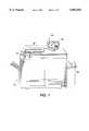
- FIG. 1is an illustration of an exemplary digital color printing system serving as an embodiment for the present invention
- FIG. 2is a block diagram of the various components comprising the system of FIG. 1;
- FIG. 3is an illustration of the placement of a document object on a platen of the scanner depicted in FIG. 1;
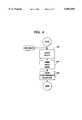
- FIG. 4is a flowchart illustrating the general processing steps carried out on the system of FIGS. 1 and 2 in accordance with the present invention
- FIGS. 5 and 6are detailed flow charts illustrating the processing steps carried out in accordance with the present invention.
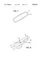
- FIGS. 7 and 8are illustrative examples of an object and an elliptical shape employed to characterize the shape of the object;
- FIGS. 9 and 10are exemplary images that may be processed in accordance with the present invention.
- FIG. 11is an exemplary illustration of an image processed in accordance with aspects of the present invention.
- datarefers herein to physical signals that indicate or include information.
- an item of datacan indicate one of a number of possible alternatives, the item of data has one of a number of "values.”
- a binary item of dataalso referred to as a "bit”
- bithas one of two values, interchangeably referred to as "1" and “0” or “ON” and “OFF” or “high” and “low.”
- a bitis an "inverse" of another bit if the two bits have different values.
- An N-bit item of datahas one of 2N values.
- a "multi-bit" item of datais an item of data that includes more than one bit.
- Memory circuitryor “memory” is any circuitry that can store data, and may include local and remote memory and input/output devices. Examples include semiconductor ROMs, RAMs, and storage medium access devices with data storage media that they can access.
- a “memory cell”is memory circuitry that can store a single unit of data, such as a bit or other n-ary digit or an analog value.
- a signal"indicates” or “selects” one of a set of alternatives if the signal causes the indicated one of the set of alternatives to occur.
- a signalcan indicate one bit set in a sequence of bit sets to be used in an operation, in which case the signal causes the indicated bit set to be used in the operation.
- An "image”is a pattern of physical light.
- An imagemay include characters, words, and text as well as other features such as graphics.
- a textmay be included in a set of one or more images, such as in images of the pages of a document.
- An imagemay be processed so as to identify specific "objects" within the image, each of which is itself an image.
- a objectmay be of any size and shape and has "physical attributes" or characteristics including, but not limited, to position, shape and orientation.
- an objectmay be a document, when the document is placed on the platen of an image input device and the region of the platen is digitized to produce a representation thereof.
- An item of data"defines" an image when the item of data includes sufficient information to produce the image.
- a two-dimensional arraycan define all or any part of an image, with each item of data in the array providing a value indicating the color of a respective location of the image.
- An item of data"defines" an image set when the item of data includes sufficient information to produce all the images in the set.
- Each location in an imagemay be called a "pixel.”
- each value indicating the color of a locationmay be called a "pixel value”.
- Each pixel valueis a bit in a "binary form” of an image, a gray scale value in a “gray scale form” of an image, or a set of color space coordinates in a "color coordinate form” of an image, the binary form, gray scale form, and color coordinate form each being a two-dimensional array defining an image.
- An operationperforms "image processing" when it operates on an item of data that relates to part of an image.
- Pixelsare "neighbors” or “neighboring” within an image when there are no other pixels between them and they meet an appropriate criterion for neighboring. If the pixels are rectangular and appear in rows and columns within a two-dimensional image, each pixel may have 4 or 8 neighboring pixels, depending on the criterion used.
- edgeoccurs in an image when two neighboring pixels have sufficiently different pixel values according to an appropriate criterion for the occurrence of an edge between them.
- edge pixelor “boundary pixel” may be applied to one or both of two neighboring pixels between which an edge occurs.
- An “image characteristic” or “characteristic”is a measurable attribute of an image.
- An operationcan “measure” a characteristic by producing data indicating the characteristic using data defining an image.
- a characteristicis measured “for an image” if the characteristic is measured in a manner that is likely to produce approximately the same result each time it occurs.
- a "version" of a first imageis a second image produced using an item of data defining the first image.
- the second imagemay be identical to the first image, or it may be modified by loss of resolution, by changing the data defining the first image, or by other processes that result in modifying pixel values of the first image.
- An “image input device”is a device that can receive an image and provide an item of data defining a version of the image.
- a “scanner”is an image input device that receives an image by a scanning operation, such as by scanning a document.
- a scannermay have a transparent surface (platen) or equivalent means to support a document during scanning.
- Other well-known image input devicesinclude digital cameras, facsimile machines, and video recorders having the capability to store data signals representative of the intensity of light reflected from the surface of objects at which the device is directed.
- An “image output device”is a device that can receive an item of data defining an image and provide or render the image as output.
- a “display”is an image output device that provides the output image in human viewable form
- a “printer”is an image output device that renders the output image in a human viewable, hard copy form.
- system 20may be a Xerox DocuColor® 40 Digital Color Printing System or the Xerox 5775® Digital Color Copier.
- System 20includes a computer or data processing unit 22 (FIG. 2) capable of receiving digital data representing an image of an original document 24 placed upon a platen of scanner 26.
- Computer 22initially stores the digital input data from scanner 26 in memory 52 (e.g., RAM or magnetic disk storage) where the image may subsequently be accessed.
- memory 52may also include program memory for the storage of object code suitable for directing the processor to execute image processing operations in accordance with the invention described herein.
- Computer 22has associated therewith a user interface (U/I) 28 including one or more user input devices 30, such as a keyboard, a keypad, a mouse, trackball, stylus or equivalent pointing device, etc.
- U/Iuser interface
- system 20is a color image output device such as printer 34 which may include a laser-driven, xerographic printing engine as found in a number of commercially available printers.
- system 20is employed to process the digital image data received as input from a scanner 26, utilizing image processing software running in processor 50, so as to produce an output file that may be rendered by printer 34, stored in memory 50, and/or transmitted to another device via network 40.
- system 20is depicted as an integrated unit in FIG. 1, it will be appreciated that the system may also comprise a plurality of independent yet interconnected units. Referring also to FIG. 3, it will be appreciated that the document placed upon the scanner platen 24 in system 20, may not be accurately registered along the registration edges 25.
- a particular embodiment to which the following description will be directedis a single document object O placed in a central location on the platen 24 as illustrated in FIG. 3.
- a facsimile transmission system using a set of rollers to advance a document through a scanning nipit will be appreciated that the document may become skewed during the digitization process and that the present application may have particular application to such systems as well.
- the present inventionautomatically identifies at least the position, shape and orientation angle of the object.
- the process carried out by computer 22, of FIG. 3 during the processing of the input imageincludes three general steps.
- the shape of the objectis modeled at step 200.
- a structured image or similar digital document format representing the image and the object thereincan be created as represented by step 300.
- the structured imagepreferably includes data representing not only the image data itself, but data representing the location, shape or orientation of the object, or some combination thereof.
- the outputmay be a page description language format or equivalents formats suitable for storing the image information in a retrievable form.
- the scanned input image(or a lower resolution version thereof is loaded into a memory frame buffer (RAM) where it is analyzed in accordance with the previously described steps.
- RAMmemory frame buffer
- the objectis distinguishable from the image background (e.g, the platen cover) and that the background of the image is contiguous.
- the object location step 100 of FIG. 4is performed by first identifying the background region of the input image 102, characterizing the background region 1 04, and then using the characteristic of the background region as a seed, identifying all the pixels representing the background region with an adaptive seed fill algorithm 106.
- Background pixelsare pixels not associated with any objects, or more simply, they are pixels representative of those regions lying outside of the objects, the values of which are controlled by the "background" against which the objects are placed during scanning (e.g., the underside of the platen cover).
- One embodimentemploys the average color of a small region in the upper left-hand corner of the scanned image as an initial estimate of the background color.
- other sampling operationsmay be employed to determine the background color as described, for example, in U.S. Pat. No. 5,282,091 for a Programmable Apparatus for Determining Document Background Level by Farrell.
- an adaptive algorithmis preferably applied to monitor the background color and to accurately identify the objects.
- An example of a seed fill algorithm suitable for use in the present inventionis described in Graphic Gems I, A. Glassner Ed., Academic Press, pp. 275-277, 1990, hereby incorporated by reference.
- An adaptive algorithmis required because the background pixels may have significant color variation resulting from a variation in illumination over the platen area.
- the adaptive seed fill algorithmis applied to the scanned color image data using an initial seed point characterized by the background, step 108, for example, the upper-left corner of the image.
- the adaptive seed fill algorithmfills the binary frame buffer with a mask indicating all contiguous pixels identified as background pixels.
- a pixelis considered to be a background pixel if its color falls within a small distance e of the current average background pixel value. This distance is calculated as an Euclidean metric in red, green, blue (RGB) color space
- pixel Pis a background pixel, else pixel P is a foreground pixel.
- the average background coloris adaptively modified at step 114 by taking the average value of the last N pixels that have been classified as background.
- the systempreferably calculates the adaptive average using the equation:
- AdAvg'is the modified average
- AdAvgis the previous adaptive average
- LastValis the value of the last pixel identified as background
- Nis the averaging window.
- thisis not a true running average, but it tracks the running average adequately and is more computationally efficient than a strict running average calculation.
- the value ofcan be adaptively modified. For example, ⁇ might be based on the standard deviation of the last several pixels identified as background, etc.
- the process of obtaining a binary map distinguishing the objects from the backgroundmay be accomplished using a simplified thresholding operation based upon the background color.
- the background colormay be a function of the color of the platen cover, such as a white cover.
- the digital color production systemmay employ a spectrally reflective or otherwise distinguishable platen cover that results in a background color that may be detected and distinguished from the objects.
- noisy edgescan be optionally smoothed (step 120) using, for example, morphological filtering.
- contiguous foreground regionsare located, step 122, thereby identifying the objects.
- Objectsare identified by scanning the background mask generated by the adaptive seed fill operation (step 106). Starting with the upper left hand pixel, the mask is searched in a scan line fashion for a pixel not classified in the mask as a background pixel--thus identifying pixels associated with a foreground object.
- the use of the seed fill algorithm for identifying the backgroundassures that foreground objects are closed, or in other words, a complete boundary is formed about the perimeter of the object.
- the boundary of an objectis identified by tracing its edge.
- the boundary of the foreground objectis traced using a simple 8-connected edge traversal operator which provides an ordered-set of points tracing the edge of the object.
- Such an edge traversal operationemploys a contour tracing operation to generate a chain code in a manner similar to word or character based recognition systems.
- An 8-connected processis described, for example, by R. Bozinovic et al. in "Off-Line Cursive Script Word Recognition", IEEE Transactions on Pattern Analysis and Machine Intelligence, Vol. 11, No. 1 (January 1989).
- the objectis added to the foreground object list and then the scanning of step 122 is continued as indicated by test step 126. Subsequent to completing the foreground scanning to identify all objects, a review of the identified objects may be completed as represented by step 130. In many cases, the scanned image may contain undesirable foreground objects; such objects can be eliminated from the object list at this step. In the situation of detecting multiple objects, one main object would preferably be selected using any of a number of techniques. For example, object selection could be accomplished by retaining the object with the largest perimeter or based upon the location of the object.
- step 200is to model the shape of the object.
- the result or output from step 100is a set of bounding pixels or a set of edge traces preferably organized in the form of a linked list. These pixels or traces can be used to extract the object, but orientation is not yet determined. To improve the quality of the object extraction, the object traces are fitted to a model shape. Orientation information, and other characteristics of the object may then be extracted from the fitted parameters.
- One method of fitting the edge traces to a rectangular shapeis a method employing binary moments for fast image bounding.
- the binary mask generated as described with respect to step 106e.g., the adaptive seed fill algorithm
- a representation of the platen imageis rendered in a binary bitmap form where each pixel value is a 0 or 1 indicating background or non-background regions.
- step 100the object edges are located and recorded as previously described, thereby providing as an input a linked list of boundary or edge pixels referred to as an edge trace, step 290.
- the second order momentsare calculated (step 292) in an efficient manner using the equation: ##EQU1## where p(i,j) is the image pixel value at image coordinates (i,j) and p n (i) is the n th order moment of the i th scan line.
- step 292approximates the moment of the object on a scanline-by-scanline basis, using the extreme boundary pixel locations.
- One method of accomplishing the calculationis to construct a list where each scanline is represented and where the list includes entries of the minimum (leftmost) and maximum (rightmost) boundary pixel of the object.
- each pixelis analyzed to determine if a scanline entry exists, if not one is created and the maximum and minimum.
- the list of scanline minimum and maximum pixel positionsmay be employed to calculate the horizontal moments (along scanlines) for each scanline, or alternatively a subset of scanlines.
- an ellipse Ecan be used to approximate the boundary of a rectangular object O R to a rough approximation.
- the best fitting ellipsehas the same area as the object and minimizes the "fitting error.”
- the following parametersare determined from the central moments. Let ##EQU4## the center of the ellipse is given by
- the center of the ellipse (xc',yc), the lengths of each axis (a and b) and the rotation angle ( ⁇ )are determined.
- the bounding box for the rectangular objectis determined as a rectangle centered at (xc,yc) with sides of length 2a and 2b, rotated by an angle ⁇ .
- B 1C-V 1 +V 2 ;
- B 3C-V 1 -V 2 .
- the rectanglemay be characterized with sides of length 2 ⁇ a and 2 ⁇ b, where a is set equal to ⁇ 3/2 or other fraction.
- FIGS. 9 and 10Examples of the bounding rectangle generated in accordance with the present invention are found in FIGS. 9 and 10.
- the object Ois bounded by an object rectangle O R , where the rectangle edges are defined by points P.
- the degraded object of FIG. 10is also found and characterized, in spite of the fact that the object representation did not have smooth, linear edges.
- the objectAfter the object has been modeled it is preferably de-rotated and repositioned in an automated fashion without user intervention. For example, referring to image object O in FIG. 9, it would be preferable to crop and derotate the image pixels within the rectangular boundary O R to automatically register the image in the center or upper-left corner of an output document image (I) such as depicted in FIG. 11.
- the automated operations enabled by the accurate identification of the image boundariesreduces or eliminates the need for extremely accurate registration of the document object on the platen. Such operations and positioning would preferably be user programmable as enabled by a user interface. Moreover, the robustness of the binary moment operations allows the system to operate in spite of imperfections or other discontinuities in the original document.
- the present inventionis a method and apparatus for automatically detecting the characteristics (e.g., size, shape, location and orientation) of a document object placed on the platen of a digital copier or similar scanning system.
- the inventionaccomplishes the detection by processing a digitized image in a highly efficient manner using binary moments, and using the moments characterizes the shape of a boundary about the object.
- the shape of the objectmay be employed to further process the image to automatically crop, derotate, and register the image at a predefined location in an output document.
Landscapes
- Engineering & Computer Science (AREA)
- Computer Vision & Pattern Recognition (AREA)
- Physics & Mathematics (AREA)
- General Physics & Mathematics (AREA)
- Theoretical Computer Science (AREA)
- Image Analysis (AREA)
Abstract
Description
d=SQRT ((P.sub.r -AdAvg.sub.r).sup.2 +(P.sub.g -AdAvg.sub.g).sup.2 +(P.sub.b -AdAvg.sub.b).sup.2),
AdAvg'=(N*AdAvg-AdAvg+LastVal)/N,
x.sub.c =m.sub.10 /m.sub.00 and
y.sub.c =m.sub.01 /m.sub.00.
V.sub.1 =(a cos (Θ),a sin (Θ)) and
V.sub.2 =(-b sin (Θ),b cos (Θ)),
Claims (13)
Priority Applications (1)
| Application Number | Priority Date | Filing Date | Title |
|---|---|---|---|
| US08/787,502US5892854A (en) | 1997-01-21 | 1997-01-21 | Automatic image registration using binary moments |
Applications Claiming Priority (1)
| Application Number | Priority Date | Filing Date | Title |
|---|---|---|---|
| US08/787,502US5892854A (en) | 1997-01-21 | 1997-01-21 | Automatic image registration using binary moments |
Publications (1)
| Publication Number | Publication Date |
|---|---|
| US5892854Atrue US5892854A (en) | 1999-04-06 |
Family
ID=25141695
Family Applications (1)
| Application Number | Title | Priority Date | Filing Date |
|---|---|---|---|
| US08/787,502Expired - LifetimeUS5892854A (en) | 1997-01-21 | 1997-01-21 | Automatic image registration using binary moments |
Country Status (1)
| Country | Link |
|---|---|
| US (1) | US5892854A (en) |
Cited By (26)
| Publication number | Priority date | Publication date | Assignee | Title |
|---|---|---|---|---|
| US6005986A (en)* | 1997-12-03 | 1999-12-21 | The United States Of America As Represented By The National Security Agency | Method of identifying the script of a document irrespective of orientation |
| US6333997B1 (en)* | 1998-06-08 | 2001-12-25 | Kabushiki Kaisha Toshiba | Image recognizing apparatus |
| WO2002035474A1 (en)* | 2000-10-27 | 2002-05-02 | Praelux Incorporated | Method and apparatus for screening chemical compounds |
| GB2373123A (en)* | 2001-01-05 | 2002-09-11 | Hewlett Packard Co | Automatic image cropping |
| US20020146173A1 (en)* | 2001-04-04 | 2002-10-10 | Herley Cormac E. | Detecting multiple objects in digital image data |
| US20030036855A1 (en)* | 1998-03-16 | 2003-02-20 | Praelux Incorporated, A Corporation Of New Jersey | Method and apparatus for screening chemical compounds |
| RU2216040C2 (en)* | 1999-07-05 | 2003-11-10 | Мицубиси Денки Кабусики Кайся | Method, device, computer program, computer system, and computer-read data medium for object representation and search on pattern |
| US6667756B2 (en) | 2001-08-27 | 2003-12-23 | Xerox Corporation | Method of shifting an image or paper to reduce show through in duplex printing |
| US20040146198A1 (en)* | 2003-01-29 | 2004-07-29 | Cormac Herley | System and method for automatically detecting and extracting objects in digital image data |
| US20040205455A1 (en)* | 2001-10-16 | 2004-10-14 | Sridhar Dathathraya | System and method for managing workflow using a plurality of scripts |
| US6839466B2 (en)* | 1999-10-04 | 2005-01-04 | Xerox Corporation | Detecting overlapping images in an automatic image segmentation device with the presence of severe bleeding |
| US6859555B1 (en)* | 2000-09-19 | 2005-02-22 | Siemens Corporate Research, Inc. | Fast dominant circle detection through horizontal and vertical scanning |
| US20050083556A1 (en)* | 2003-10-20 | 2005-04-21 | Carlson Gerard J. | Image cropping based on imaged cropping markers |
| US20060072818A1 (en)* | 2004-09-30 | 2006-04-06 | Microsoft Corporation | Method and system for automatically inscribing noisy objects in scanned image data within a minimum area rectangle |
| US20060083418A1 (en)* | 2003-02-11 | 2006-04-20 | Qinetiq Limited | Image analysis |
| US20070112797A1 (en)* | 2005-11-16 | 2007-05-17 | Konica Minolta Business Technologies, Inc. | Information processing apparatus and image processing apparatus executing script stored in association with storage region |
| US20090040569A1 (en)* | 2007-08-10 | 2009-02-12 | Mark Joseph Hamzy | Method and system for adjusting scanned images |
| US20100014774A1 (en)* | 2008-07-17 | 2010-01-21 | Lawrence Shao-Hsien Chen | Methods and Systems for Content-Boundary Detection |
| USRE41364E1 (en)* | 2000-02-18 | 2010-06-01 | Yu-Fen Tsai | Method for determining scan line misalignments |
| US20100329571A1 (en)* | 2009-06-24 | 2010-12-30 | General Electric Company | Shape based registration |
| US20110142341A1 (en)* | 2009-12-16 | 2011-06-16 | Dolan John E | Methods and Systems for Automatic Content-Boundary Detection |
| US8427483B1 (en)* | 2010-08-30 | 2013-04-23 | Disney Enterprises. Inc. | Drawing figures in computer-based drawing applications |
| US8487932B1 (en) | 2010-08-30 | 2013-07-16 | Disney Enterprises, Inc. | Drawing figures in computer-based drawing applications |
| US8884916B2 (en) | 2010-12-09 | 2014-11-11 | Synaptics Incorporated | System and method for determining user input using polygons |
| US9411445B2 (en) | 2013-06-27 | 2016-08-09 | Synaptics Incorporated | Input object classification |
| US9804717B2 (en) | 2015-03-11 | 2017-10-31 | Synaptics Incorporated | Input sensing and exclusion |
Citations (14)
| Publication number | Priority date | Publication date | Assignee | Title |
|---|---|---|---|---|
| US3846755A (en)* | 1969-12-15 | 1974-11-05 | Electronic Reading Syst | Pattern recognition system |
| US4181952A (en)* | 1977-11-21 | 1980-01-01 | International Business Machines Corporation | Method and means for minimizing error between the manual digitizing of points and the actual location of said points on an _electronic data entry surface |
| US4649498A (en)* | 1984-05-08 | 1987-03-10 | The University Of Rochester | Computer systems for curve-solid classification and solid modeling |
| US4922350A (en)* | 1988-03-30 | 1990-05-01 | Eastman Kodak Company | Document recognition with forward direction scan for detecting the boundaries of an original document and reverse direction scan for producing recorded image on the original document |
| US4922543A (en)* | 1984-12-14 | 1990-05-01 | Sten Hugo Nils Ahlbom | Image processing device |
| US5115476A (en)* | 1990-01-29 | 1992-05-19 | Fuji Photo Film Co., Ltd. | Edge finding method and apparatus |
| US5220398A (en)* | 1990-09-28 | 1993-06-15 | Massachusetts Institute Of Technology | Analog VLSI microchip for object position and orientation |
| US5253765A (en)* | 1993-01-14 | 1993-10-19 | L.M.B. Electronics, Inc. | Sorting and grading system |
| US5485568A (en)* | 1993-10-08 | 1996-01-16 | Xerox Corporation | Structured image (Sl) format for describing complex color raster images |
| US5528387A (en)* | 1994-11-23 | 1996-06-18 | Xerox Corporation | Electronic image registration for a scanner |
| US5533144A (en)* | 1994-10-17 | 1996-07-02 | Xerox Corporation | Anti-counterfeit pattern detector and method |
| US5619593A (en)* | 1991-09-12 | 1997-04-08 | Fuji Photo Film Co., Ltd. | Method for extracting object images and method for detecting movements thereof |
| US5649021A (en)* | 1995-06-07 | 1997-07-15 | David Sarnoff Research Center, Inc. | Method and system for object detection for instrument control |
| US5694486A (en)* | 1994-02-07 | 1997-12-02 | Canon Kabushiki Kaisha | Image processing apparatus and method for designating one of a plurality of operating modes |
- 1997
- 1997-01-21USUS08/787,502patent/US5892854A/ennot_activeExpired - Lifetime
Patent Citations (14)
| Publication number | Priority date | Publication date | Assignee | Title |
|---|---|---|---|---|
| US3846755A (en)* | 1969-12-15 | 1974-11-05 | Electronic Reading Syst | Pattern recognition system |
| US4181952A (en)* | 1977-11-21 | 1980-01-01 | International Business Machines Corporation | Method and means for minimizing error between the manual digitizing of points and the actual location of said points on an _electronic data entry surface |
| US4649498A (en)* | 1984-05-08 | 1987-03-10 | The University Of Rochester | Computer systems for curve-solid classification and solid modeling |
| US4922543A (en)* | 1984-12-14 | 1990-05-01 | Sten Hugo Nils Ahlbom | Image processing device |
| US4922350A (en)* | 1988-03-30 | 1990-05-01 | Eastman Kodak Company | Document recognition with forward direction scan for detecting the boundaries of an original document and reverse direction scan for producing recorded image on the original document |
| US5115476A (en)* | 1990-01-29 | 1992-05-19 | Fuji Photo Film Co., Ltd. | Edge finding method and apparatus |
| US5220398A (en)* | 1990-09-28 | 1993-06-15 | Massachusetts Institute Of Technology | Analog VLSI microchip for object position and orientation |
| US5619593A (en)* | 1991-09-12 | 1997-04-08 | Fuji Photo Film Co., Ltd. | Method for extracting object images and method for detecting movements thereof |
| US5253765A (en)* | 1993-01-14 | 1993-10-19 | L.M.B. Electronics, Inc. | Sorting and grading system |
| US5485568A (en)* | 1993-10-08 | 1996-01-16 | Xerox Corporation | Structured image (Sl) format for describing complex color raster images |
| US5694486A (en)* | 1994-02-07 | 1997-12-02 | Canon Kabushiki Kaisha | Image processing apparatus and method for designating one of a plurality of operating modes |
| US5533144A (en)* | 1994-10-17 | 1996-07-02 | Xerox Corporation | Anti-counterfeit pattern detector and method |
| US5528387A (en)* | 1994-11-23 | 1996-06-18 | Xerox Corporation | Electronic image registration for a scanner |
| US5649021A (en)* | 1995-06-07 | 1997-07-15 | David Sarnoff Research Center, Inc. | Method and system for object detection for instrument control |
Non-Patent Citations (8)
| Title |
|---|
| 1995 Proceedings, vol. 1; Technical Association of the Graphic Arts; "Managing and Representing Image Workflow in Prepress Applications"; Dennis L. Venable, Rob Buckley, and Toshiya Yamada; pp. 373-385. |
| 1995 Proceedings, vol. 1; Technical Association of the Graphic Arts; Managing and Representing Image Workflow in Prepress Applications ; Dennis L. Venable, Rob Buckley, and Toshiya Yamada; pp. 373 385.* |
| Graphics Gems I, A. Glassner, Ed. Academic Press, "A Deed Fill Algorithm", pp. 275-277, 1990. |
| Graphics Gems I, A. Glassner, Ed. Academic Press, A Deed Fill Algorithm , pp. 275 277, 1990.* |
| Klaus Voss and Herbert Suesse; ". . . Fitting of Planar Objects by Primitives"; 1015-4651/96; 1996 IEEE Proceedings of ICPR '96; pp. 508-512. |
| Klaus Voss and Herbert Suesse; . . . Fitting of Planar Objects by Primitives ; 1015 4651/96; 1996 IEEE Proceedings of ICPR 96; pp. 508 512.* |
| Radmilo M. Bozinovic and Sargur N. Srihari; "Off-Line Cursive Script Word Recognition"; IEEE Transactions on Pattern Analysis and Machine Intelligence, vol. 11, No. 1, Jan. 1989 pp. 68-83. |
| Radmilo M. Bozinovic and Sargur N. Srihari; Off Line Cursive Script Word Recognition ; IEEE Transactions on Pattern Analysis and Machine Intelligence, vol. 11, No. 1, Jan. 1989 pp. 68 83.* |
Cited By (57)
| Publication number | Priority date | Publication date | Assignee | Title |
|---|---|---|---|---|
| US6005986A (en)* | 1997-12-03 | 1999-12-21 | The United States Of America As Represented By The National Security Agency | Method of identifying the script of a document irrespective of orientation |
| US20030036855A1 (en)* | 1998-03-16 | 2003-02-20 | Praelux Incorporated, A Corporation Of New Jersey | Method and apparatus for screening chemical compounds |
| US7957911B2 (en) | 1998-03-16 | 2011-06-07 | Ge Healthcare Bio-Sciences Corp. | Method and apparatus for screening chemical compounds |
| US20080262741A1 (en)* | 1998-03-16 | 2008-10-23 | Ge Healthcare Bio-Sciences Corp. | Method and apparatus for screening chemical compounds |
| US6333997B1 (en)* | 1998-06-08 | 2001-12-25 | Kabushiki Kaisha Toshiba | Image recognizing apparatus |
| US7505637B2 (en) | 1999-07-05 | 2009-03-17 | Mitsubishi Denki Kabushiki Kaisha | Method, apparatus, computer program, computer system, and computer-readable storage medium for representing and searching for an object in an image |
| US20080065610A1 (en)* | 1999-07-05 | 2008-03-13 | Bober Miroslaw Z | Method, apparatus, computer program, computer system, and computer-readable storage medium for representing and searching for an object in an image |
| US7542626B2 (en) | 1999-07-05 | 2009-06-02 | Mitsubishi Denki Kabushiki Kaisha | Method, apparatus, computer program, computer system, and computer-readable storage medium for representing and searching for an object in an image |
| US20070065016A1 (en)* | 1999-07-05 | 2007-03-22 | Bober Miroslaw Z | Method, apparatus, computer program, computer system, and computer-readable storage medium for representing and searching for an object in an image |
| US7492972B2 (en) | 1999-07-05 | 2009-02-17 | Mitsubishi Denki Kabushiki Kaisha | Method, apparatus, computer program, computer system, and computer-readable storage medium for representing and searching for an object in an image |
| US7483594B2 (en) | 1999-07-05 | 2009-01-27 | Mitsubishi Denki Kabushiki Kaisha | Method, apparatus, computer program, computer system, and computer-readable storage medium for representing and searching for an object in an image |
| CN1967543B (en)* | 1999-07-05 | 2010-05-26 | 三菱电机株式会社 | Method and device for representing or retrieving objects in images |
| US20080044108A1 (en)* | 1999-07-05 | 2008-02-21 | Bober Miroslaw Z | Method, apparatus, computer program, computer system, and computer-readable storage medium for representing and searching for an object in an image |
| US7356203B2 (en) | 1999-07-05 | 2008-04-08 | Mitsubishi Denki Kabushiki Kaisha | Method, apparatus, computer program, computer system, and computer-readable storage medium for representing and searching for an object in an image |
| US6882756B1 (en) | 1999-07-05 | 2005-04-19 | Mitsubishi Denki Kabushiki Kaisha | Method and device for displaying or searching for object in image and computer-readable storage medium |
| RU2216040C2 (en)* | 1999-07-05 | 2003-11-10 | Мицубиси Денки Кабусики Кайся | Method, device, computer program, computer system, and computer-read data medium for object representation and search on pattern |
| US20080050049A1 (en)* | 1999-07-05 | 2008-02-28 | Bober Miroslaw Z | Method, apparatus, computer program, computer system, and computer-readable storage medium for representing and searching for an object in an image |
| US20080050048A1 (en)* | 1999-07-05 | 2008-02-28 | Bober Miroslaw Z | Method, apparatus, computer program, computer system, and computer-readable storage medium for representing and searching for an object in an image |
| US6839466B2 (en)* | 1999-10-04 | 2005-01-04 | Xerox Corporation | Detecting overlapping images in an automatic image segmentation device with the presence of severe bleeding |
| USRE41364E1 (en)* | 2000-02-18 | 2010-06-01 | Yu-Fen Tsai | Method for determining scan line misalignments |
| US6859555B1 (en)* | 2000-09-19 | 2005-02-22 | Siemens Corporate Research, Inc. | Fast dominant circle detection through horizontal and vertical scanning |
| WO2002035474A1 (en)* | 2000-10-27 | 2002-05-02 | Praelux Incorporated | Method and apparatus for screening chemical compounds |
| US7034848B2 (en) | 2001-01-05 | 2006-04-25 | Hewlett-Packard Development Company, L.P. | System and method for automatically cropping graphical images |
| GB2373123A (en)* | 2001-01-05 | 2002-09-11 | Hewlett Packard Co | Automatic image cropping |
| GB2373123B (en)* | 2001-01-05 | 2005-06-01 | Hewlett Packard Co | System and method for automatically cropping graphical images |
| US7058224B2 (en) | 2001-04-04 | 2006-06-06 | Microsfot Corporation | Detecting multiple objects in digital image data |
| US20020146173A1 (en)* | 2001-04-04 | 2002-10-10 | Herley Cormac E. | Detecting multiple objects in digital image data |
| US20050163382A1 (en)* | 2001-04-04 | 2005-07-28 | Microsoft Corporation | Detecting multiple objects in digital image data |
| US6901167B2 (en)* | 2001-04-04 | 2005-05-31 | Microsoft Corporation | Detecting multiple objects in digital image data |
| US20040036847A1 (en)* | 2001-08-27 | 2004-02-26 | Xerox Corporation | Method of shifting an image or paper to reduce show through in duplex printing |
| US6667756B2 (en) | 2001-08-27 | 2003-12-23 | Xerox Corporation | Method of shifting an image or paper to reduce show through in duplex printing |
| US6806896B2 (en) | 2001-08-27 | 2004-10-19 | Xerox Corporation | Method of shifting an image or paper to reduce show through in duplex printing |
| US20040205455A1 (en)* | 2001-10-16 | 2004-10-14 | Sridhar Dathathraya | System and method for managing workflow using a plurality of scripts |
| US20040146198A1 (en)* | 2003-01-29 | 2004-07-29 | Cormac Herley | System and method for automatically detecting and extracting objects in digital image data |
| US7162084B2 (en)* | 2003-01-29 | 2007-01-09 | Microsoft Corporation | System and method for automatically detecting and extracting objects in digital image data |
| US20060083418A1 (en)* | 2003-02-11 | 2006-04-20 | Qinetiq Limited | Image analysis |
| US7684596B2 (en)* | 2003-02-11 | 2010-03-23 | Qinetiq Limited | Image analysis |
| US20050083556A1 (en)* | 2003-10-20 | 2005-04-21 | Carlson Gerard J. | Image cropping based on imaged cropping markers |
| US7623734B2 (en)* | 2004-09-30 | 2009-11-24 | Microsoft Corporation | Method and system for automatically inscribing noisy objects in scanned image data within a minimum area rectangle |
| US20060072818A1 (en)* | 2004-09-30 | 2006-04-06 | Microsoft Corporation | Method and system for automatically inscribing noisy objects in scanned image data within a minimum area rectangle |
| US8004723B2 (en)* | 2005-11-16 | 2011-08-23 | Konica Minolta Business Technologies, Inc. | Information processing apparatus and image processing apparatus executing script stored in association with storage region |
| US20070112797A1 (en)* | 2005-11-16 | 2007-05-17 | Konica Minolta Business Technologies, Inc. | Information processing apparatus and image processing apparatus executing script stored in association with storage region |
| US20090040569A1 (en)* | 2007-08-10 | 2009-02-12 | Mark Joseph Hamzy | Method and system for adjusting scanned images |
| US8120810B2 (en)* | 2007-08-10 | 2012-02-21 | International Business Machines Corporation | Method and system for adjusting scanned images |
| US20100014774A1 (en)* | 2008-07-17 | 2010-01-21 | Lawrence Shao-Hsien Chen | Methods and Systems for Content-Boundary Detection |
| US9547799B2 (en) | 2008-07-17 | 2017-01-17 | Sharp Laboratories Of America, Inc. | Methods and systems for content-boundary detection |
| US20100329571A1 (en)* | 2009-06-24 | 2010-12-30 | General Electric Company | Shape based registration |
| US20110142341A1 (en)* | 2009-12-16 | 2011-06-16 | Dolan John E | Methods and Systems for Automatic Content-Boundary Detection |
| US8873864B2 (en) | 2009-12-16 | 2014-10-28 | Sharp Laboratories Of America, Inc. | Methods and systems for automatic content-boundary detection |
| US8427483B1 (en)* | 2010-08-30 | 2013-04-23 | Disney Enterprises. Inc. | Drawing figures in computer-based drawing applications |
| US8487932B1 (en) | 2010-08-30 | 2013-07-16 | Disney Enterprises, Inc. | Drawing figures in computer-based drawing applications |
| US8884916B2 (en) | 2010-12-09 | 2014-11-11 | Synaptics Incorporated | System and method for determining user input using polygons |
| US9001070B2 (en) | 2010-12-09 | 2015-04-07 | Synaptics Incorporated | System and method for determining user input from occluded objects |
| US10168843B2 (en) | 2010-12-09 | 2019-01-01 | Synaptics Incorporated | System and method for determining user input from occluded objects |
| US9411445B2 (en) | 2013-06-27 | 2016-08-09 | Synaptics Incorporated | Input object classification |
| US9804717B2 (en) | 2015-03-11 | 2017-10-31 | Synaptics Incorporated | Input sensing and exclusion |
| US9959002B2 (en) | 2015-03-11 | 2018-05-01 | Synaptics Incorprated | System and method for input sensing |
Similar Documents
| Publication | Publication Date | Title |
|---|---|---|
| US5892854A (en) | Automatic image registration using binary moments | |
| US6839466B2 (en) | Detecting overlapping images in an automatic image segmentation device with the presence of severe bleeding | |
| US6738154B1 (en) | Locating the position and orientation of multiple objects with a smart platen | |
| US6704456B1 (en) | Automatic image segmentation in the presence of severe background bleeding | |
| US7330604B2 (en) | Model-based dewarping method and apparatus | |
| US8861845B2 (en) | Detecting and correcting redeye in an image | |
| US6898316B2 (en) | Multiple image area detection in a digital image | |
| US7454040B2 (en) | Systems and methods of detecting and correcting redeye in an image suitable for embedded applications | |
| JP2986383B2 (en) | Method and apparatus for correcting skew for line scan images | |
| JP3883696B2 (en) | Method for scanning and detecting multiple photos and removing artificial edges | |
| US7593595B2 (en) | Photographic document imaging system | |
| US8055065B2 (en) | Vectorisation of colour gradients | |
| US20120294528A1 (en) | Method of Detecting and Correcting Digital Images of Books in the Book Spine Area | |
| JPH03201866A (en) | Decision of picture skew angle from data including data of compressed form | |
| KR20020018936A (en) | Apparatus and method for correcting distortion of input image | |
| CN113392819B (en) | Batch academic image automatic segmentation and labeling device and method | |
| US20060164517A1 (en) | Method for digital recording, storage and/or transmission of information by means of a camera provided on a comunication terminal | |
| EP0975146B1 (en) | Locating the position and orientation of multiple objects with a smart platen | |
| EP0702320A1 (en) | Skew detection | |
| EP0974931A1 (en) | Method and apparatus for identifying a plurality of sub-images in an input image | |
| Konya et al. | Adaptive methods for robust document image understanding | |
| AU2020273367A1 (en) | Photographic document imaging system | |
| US6717697B1 (en) | Image-component rendering method and recording medium in which image-component rendering program is recorded | |
| JPH10222688A (en) | Picture processing method | |
| AU2006294425B2 (en) | Vectorisation of colour gradients |
Legal Events
| Date | Code | Title | Description |
|---|---|---|---|
| AS | Assignment | Owner name:XEROX CORPORATION, CONNECTICUT Free format text:ASSIGNMENT OF ASSIGNORS INTEREST;ASSIGNORS:DE QUEIROZ, RICARDO L.;VENABLE, DENNIS L.;REEL/FRAME:008405/0905 Effective date:19961218 | |
| STCF | Information on status: patent grant | Free format text:PATENTED CASE | |
| AS | Assignment | Owner name:BANK ONE, NA, AS ADMINISTRATIVE AGENT, ILLINOIS Free format text:SECURITY INTEREST;ASSIGNOR:XEROX CORPORATION;REEL/FRAME:013153/0001 Effective date:20020621 | |
| FPAY | Fee payment | Year of fee payment:4 | |
| AS | Assignment | Owner name:JPMORGAN CHASE BANK, AS COLLATERAL AGENT, TEXAS Free format text:SECURITY AGREEMENT;ASSIGNOR:XEROX CORPORATION;REEL/FRAME:015134/0476 Effective date:20030625 Owner name:JPMORGAN CHASE BANK, AS COLLATERAL AGENT,TEXAS Free format text:SECURITY AGREEMENT;ASSIGNOR:XEROX CORPORATION;REEL/FRAME:015134/0476 Effective date:20030625 | |
| FPAY | Fee payment | Year of fee payment:8 | |
| FPAY | Fee payment | Year of fee payment:12 | |
| AS | Assignment | Owner name:XEROX CORPORATION, CONNECTICUT Free format text:RELEASE BY SECURED PARTY;ASSIGNOR:JPMORGAN CHASE BANK, N.A. AS SUCCESSOR-IN-INTEREST ADMINISTRATIVE AGENT AND COLLATERAL AGENT TO JPMORGAN CHASE BANK;REEL/FRAME:066728/0193 Effective date:20220822 |