US5892577A - Apparatus and method for carrying out analysis of samples - Google Patents
Apparatus and method for carrying out analysis of samplesDownload PDFInfo
- Publication number
- US5892577A US5892577AUS08/809,402US80940297AUS5892577AUS 5892577 AUS5892577 AUS 5892577AUS 80940297 AUS80940297 AUS 80940297AUS 5892577 AUS5892577 AUS 5892577A
- Authority
- US
- United States
- Prior art keywords
- disc
- substrate
- light
- sample
- detector
- Prior art date
- Legal status (The legal status is an assumption and is not a legal conclusion. Google has not performed a legal analysis and makes no representation as to the accuracy of the status listed.)
- Expired - Fee Related
Links
- 238000000034methodMethods0.000titleclaimsabstractdescription18
- 238000004458analytical methodMethods0.000titleclaimsdescription9
- 239000000758substrateSubstances0.000claimsabstractdescription50
- 230000003287optical effectEffects0.000claimsabstractdescription33
- 238000007689inspectionMethods0.000claimsabstractdescription12
- 239000000126substanceSubstances0.000claimsabstractdescription8
- 230000005670electromagnetic radiationEffects0.000claimsdescription28
- 230000005855radiationEffects0.000claimsdescription18
- 238000001228spectrumMethods0.000claims1
- 239000000523sampleSubstances0.000description39
- 239000000463materialSubstances0.000description29
- 239000010410layerSubstances0.000description27
- 229920003023plasticPolymers0.000description12
- 239000000499gelSubstances0.000description8
- 238000002965ELISAMethods0.000description7
- 210000004027cellAnatomy0.000description7
- 102000004190EnzymesHuman genes0.000description6
- 108090000790EnzymesProteins0.000description6
- 239000000427antigenSubstances0.000description6
- 102000036639antigensHuman genes0.000description6
- 108091007433antigensProteins0.000description6
- 239000011248coating agentSubstances0.000description5
- 238000000576coating methodMethods0.000description5
- 239000011358absorbing materialSubstances0.000description4
- 238000010586diagramMethods0.000description4
- 229910052751metalInorganic materials0.000description4
- 239000002184metalSubstances0.000description4
- 239000012491analyteSubstances0.000description3
- 210000004369bloodAnatomy0.000description3
- 239000008280bloodSubstances0.000description3
- 239000002244precipitateSubstances0.000description3
- 239000004411aluminiumSubstances0.000description2
- 229910052782aluminiumInorganic materials0.000description2
- XAGFODPZIPBFFR-UHFFFAOYSA-NaluminiumChemical compound[Al]XAGFODPZIPBFFR-UHFFFAOYSA-N0.000description2
- 230000006835compressionEffects0.000description2
- 238000007906compressionMethods0.000description2
- 238000001962electrophoresisMethods0.000description2
- PCHJSUWPFVWCPO-UHFFFAOYSA-NgoldChemical compound[Au]PCHJSUWPFVWCPO-UHFFFAOYSA-N0.000description2
- 239000010931goldSubstances0.000description2
- 229910052737goldInorganic materials0.000description2
- 230000002452interceptive effectEffects0.000description2
- 238000012986modificationMethods0.000description2
- 230000004048modificationEffects0.000description2
- 238000004204optical analysis methodMethods0.000description2
- 102000004169proteins and genesHuman genes0.000description2
- 108090000623proteins and genesProteins0.000description2
- 238000010186stainingMethods0.000description2
- 238000012360testing methodMethods0.000description2
- 208000036142Viral infectionDiseases0.000description1
- 230000002745absorbentEffects0.000description1
- 239000002250absorbentSubstances0.000description1
- 238000003556assayMethods0.000description1
- 238000004166bioassayMethods0.000description1
- 238000010256biochemical assayMethods0.000description1
- 239000012472biological sampleSubstances0.000description1
- 230000005540biological transmissionEffects0.000description1
- 238000004113cell cultureMethods0.000description1
- 238000006243chemical reactionMethods0.000description1
- 230000001427coherent effectEffects0.000description1
- 238000010276constructionMethods0.000description1
- 238000007405data analysisMethods0.000description1
- 238000013500data storageMethods0.000description1
- 238000001514detection methodMethods0.000description1
- 238000006073displacement reactionMethods0.000description1
- 230000000694effectsEffects0.000description1
- 238000005516engineering processMethods0.000description1
- 238000007373indentationMethods0.000description1
- 230000001939inductive effectEffects0.000description1
- 238000002372labellingMethods0.000description1
- 238000013507mappingMethods0.000description1
- 238000005497microtitrationMethods0.000description1
- 238000009595pap smearMethods0.000description1
- 238000000059patterningMethods0.000description1
- 230000002093peripheral effectEffects0.000description1
- 238000000206photolithographyMethods0.000description1
- 210000002381plasmaAnatomy0.000description1
- 230000010287polarizationEffects0.000description1
- 238000002360preparation methodMethods0.000description1
- 239000011241protective layerSubstances0.000description1
- 238000004445quantitative analysisMethods0.000description1
- 238000005070samplingMethods0.000description1
- 238000012216screeningMethods0.000description1
- 239000004065semiconductorSubstances0.000description1
- 210000001519tissueAnatomy0.000description1
- 238000012546transferMethods0.000description1
- 239000012780transparent materialSubstances0.000description1
- 230000009385viral infectionEffects0.000description1
Images


Classifications
- G—PHYSICS
- G01—MEASURING; TESTING
- G01N—INVESTIGATING OR ANALYSING MATERIALS BY DETERMINING THEIR CHEMICAL OR PHYSICAL PROPERTIES
- G01N21/00—Investigating or analysing materials by the use of optical means, i.e. using sub-millimetre waves, infrared, visible or ultraviolet light
- G01N21/17—Systems in which incident light is modified in accordance with the properties of the material investigated
- G01N21/25—Colour; Spectral properties, i.e. comparison of effect of material on the light at two or more different wavelengths or wavelength bands
- G01N21/251—Colorimeters; Construction thereof
- G01N21/253—Colorimeters; Construction thereof for batch operation, i.e. multisample apparatus
- G—PHYSICS
- G01—MEASURING; TESTING
- G01N—INVESTIGATING OR ANALYSING MATERIALS BY DETERMINING THEIR CHEMICAL OR PHYSICAL PROPERTIES
- G01N35/00—Automatic analysis not limited to methods or materials provided for in any single one of groups G01N1/00 - G01N33/00; Handling materials therefor
- G01N35/00029—Automatic analysis not limited to methods or materials provided for in any single one of groups G01N1/00 - G01N33/00; Handling materials therefor provided with flat sample substrates, e.g. slides
- G01N35/00069—Automatic analysis not limited to methods or materials provided for in any single one of groups G01N1/00 - G01N33/00; Handling materials therefor provided with flat sample substrates, e.g. slides whereby the sample substrate is of the bio-disk type, i.e. having the format of an optical disk
- G—PHYSICS
- G01—MEASURING; TESTING
- G01N—INVESTIGATING OR ANALYSING MATERIALS BY DETERMINING THEIR CHEMICAL OR PHYSICAL PROPERTIES
- G01N35/00—Automatic analysis not limited to methods or materials provided for in any single one of groups G01N1/00 - G01N33/00; Handling materials therefor
- G01N35/02—Automatic analysis not limited to methods or materials provided for in any single one of groups G01N1/00 - G01N33/00; Handling materials therefor using a plurality of sample containers moved by a conveyor system past one or more treatment or analysis stations
- G01N35/025—Automatic analysis not limited to methods or materials provided for in any single one of groups G01N1/00 - G01N33/00; Handling materials therefor using a plurality of sample containers moved by a conveyor system past one or more treatment or analysis stations having a carousel or turntable for reaction cells or cuvettes
- B—PERFORMING OPERATIONS; TRANSPORTING
- B01—PHYSICAL OR CHEMICAL PROCESSES OR APPARATUS IN GENERAL
- B01J—CHEMICAL OR PHYSICAL PROCESSES, e.g. CATALYSIS OR COLLOID CHEMISTRY; THEIR RELEVANT APPARATUS
- B01J2219/00—Chemical, physical or physico-chemical processes in general; Their relevant apparatus
- B01J2219/00274—Sequential or parallel reactions; Apparatus and devices for combinatorial chemistry or for making arrays; Chemical library technology
- B01J2219/00277—Apparatus
- B01J2219/00497—Features relating to the solid phase supports
- B01J2219/00527—Sheets
- B01J2219/00536—Sheets in the shape of disks
- G—PHYSICS
- G01—MEASURING; TESTING
- G01N—INVESTIGATING OR ANALYSING MATERIALS BY DETERMINING THEIR CHEMICAL OR PHYSICAL PROPERTIES
- G01N35/00—Automatic analysis not limited to methods or materials provided for in any single one of groups G01N1/00 - G01N33/00; Handling materials therefor
- G01N35/02—Automatic analysis not limited to methods or materials provided for in any single one of groups G01N1/00 - G01N33/00; Handling materials therefor using a plurality of sample containers moved by a conveyor system past one or more treatment or analysis stations
- G01N35/04—Details of the conveyor system
- G01N2035/0439—Rotary sample carriers, i.e. carousels
- G01N2035/0458—Multiple concentric rows of wells
- G—PHYSICS
- G01—MEASURING; TESTING
- G01N—INVESTIGATING OR ANALYSING MATERIALS BY DETERMINING THEIR CHEMICAL OR PHYSICAL PROPERTIES
- G01N21/00—Investigating or analysing materials by the use of optical means, i.e. using sub-millimetre waves, infrared, visible or ultraviolet light
- G01N21/62—Systems in which the material investigated is excited whereby it emits light or causes a change in wavelength of the incident light
- G01N21/63—Systems in which the material investigated is excited whereby it emits light or causes a change in wavelength of the incident light optically excited
- G01N21/64—Fluorescence; Phosphorescence
Definitions
- the present inventionrelates to apparatus and to a method for carrying out optical analysis of samples and is applicable in particular to the analysis of biological, chemical and biochemical samples.
- an enzyme-linked immunosorbent assaycan be carried out which produces a visible coloured deposit if the antibody is present.
- An ELISAmakes use of a surface which is coated with an antigen specific to the antibody to be tested for. Upon exposure of the surface to the blood sample, antibodies in the sample bind to the antigens.
- optical analysis techniquesare open to human error because of their subjective nature. These techniques are also not suited to uses where a high throughput of samples is required, for example in blood screening applications or cervical smear tests, and are thus relatively expensive to use. The cost factor is exacerbated because, more often than not, different equipment is required for each particular technique.
- An object of the present inventionis to provide a technique for carrying out the optical analysis of samples which overcomes or at least mitigates certain of these disadvantages.
- a detectoris arranged to detect light reflected from, or transmitted through that surface, and to determine from analysis of the detected light whether the light beam has been interfered with by the sample material.
- a method of conducting an optical inspection of a biological, chemical, or biochemical samplecomprising the steps of:
- a system for automatically carrying out an optical inspection of a sample to determine whether or not the sample comprises material which interferes with incident electromagnetic radiationcomprising:
- a source of electromagnetic radiationfor providing a beam of electromagnetic radiation
- detector meanswhich in use is arranged to detect electromagnetic radiation reflected from and/or passing through the substrate and the sample, the substrate being provided with distributed electromagnetic radiation modulating means for modulating at least a part of said beam with a digitally encoded position address indicative of the location on said surface on which the beam is currently directed, the detector means being arranged to decode the modulated electromagnetic radiation beam to determine the encoded address and to determine if the received beam has been modulated by any of said material which may be present in the sample.
- the present inventionenables the rapid scanning of a surface coated with components from a sample to determine their presence and also if necessary their optical properties.
- the systemis particularly suited for carrying out the automatic inspection of samples with a high throughput.
- provision of address information in or on the substrateenables the precise position of the electromagnetic radiation beam on the surface to be determined which in turn allows the accurate mapping of optical data, corresponding to attached material, to the surface. This enables regions of interest on the surface to be easily and quickly re-located.
- the present inventionis suited to carrying out ELISA where the specific antigen is coated onto the surface of the substrate. The surface is then exposed to the analyte and subsequently the specific enzyme and the resulting sample scanned to detect and quantify the enzyme linked to the surface.
- the systemis also suited to carrying out histological analysis and to the quantitative study of gels run using electrophoresis.
- the electromagnetic radiationis light, e.g. infra-red, visible or ultra-violet.
- a system for automatically carrying out an optical inspection of a sample to determine whether or not the sample comprises material which interferes with incident electromagnetic radiationcomprising:
- a substantially planar substratehaving a surface for supporting the sample
- a source of electromagnetic radiationfor providing a beam of electromagnetic radiation
- a first detector -ordetecting electromagnetic radiation reflected from the substrate and the sample
- a second detectorfor detecting electromagnetic radiation passing through the substrate and the sample
- control meanscoupled to the first and second detectors and for causing said beam to scan the surface of the substrate in dependence upon one or both of the outputs of the detectors and for detecting the presence of said components.
- control meansis arranged to determine the difference between output signals provided by said first and second detectors, which are representative of the signals detected, for the purpose of detecting said material without signal artifacts arising from, for example, dirt present on the side of the substrate opposite the support surface.
- the substratemay be provided with distributed address means for modulating the light beam with digitally encoded position information indicative of the area currently being scanned by the light beam, one or other of the detectors being arranged to decode the received light signal to determine the address of the location on which the light beam is incident.
- a system for automatically carrying out an optical inspection of a sample to determine whether or not the sample comprises material which interferes with incident electromagnetic radiationcomprising:
- a disccomprising a plastic base layer on the upper surface of which is formed a plurality of perturbations, for interfering with incident electromagnetic radiation, representing digitally encoded data, and a surface for supporting the sample;
- disc reading apparatusincluding a source of electromagnetic radiation for providing a beam of electromagnetic radiation, scanning means for scanning the beam across the upper surface of the disk, and an electromagnetic radiation detector for detecting radiation reflected from and/or transmitted through the disk and said sample components; and
- the beamis additionally modulated by any of said material which is attached to the support surface of the disc.
- said electromagnetic radiationis visible light although infra-red or ultra-violet radiation may be suitable.
- the disccomprises a lower layer of transparent plastic on the surface of which is impressed, or otherwise produced, said digital information.
- This surfaceis coated with a partially reflective layer, for example of aluminium, which in turn may be covered by a further layer of transparent plastic.
- the upper surface of the discis provided with a 3D surface topology arranged to provide growth and attachment cues for cells grown on the surface.
- the surfacemay be provided with a rectangular grating for causing cells to align in a chosen direction.
- growth and attachment cuesmay be provided by chemical patterning of the surface, e.g. using fibrenectin, produced, for example, using photolithography.
- the upper surface of the discis coated with a gel suitable for carrying out electrophoresis on proteins, DNA etc.
- a first electrodemay be provided at the centre of the disc with a second electrode being provided around the periphery of the disc.
- a wellmay be formed in the gel into which the analyte can be placed.
- the discmay be provided with a calibration track, e.g. a series of 256 grey levels. These levels may be printed onto the surface of the track using an ink jet printer.
- a substrate for use in a systemwhich is arranged to carry out an optical inspection on the substrate to determine whether or not material which interferes with incident electromagnetic radiation is present on a surface of the substrate, the substrate including a preformed calibration scale which enables calibration of said system.
- the calibration scaleis a series of graded grey regions which reflect or transmit light to varying degrees.
- This scalemay be printed on a surface of the substrate using an ink jet printer.
- apparatus for conducting an optical inspection of a biological, chemical, or biochemical sample supported on a substratecomprising;
- a source of electromagnetic radiationfor providing a beam of electromagnetic radiation
- detector meansfor detecting radiation reflected from or transmitted through the substrate and sample and for providing an output signal corresponding to the detected radiation.
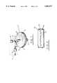
- FIG. 1shows a diagrammatic view of a first embodiment of the present invention
- FIG. 2shows a cross-sectional view of a part of a disc for use with the embodiment of FIG. 1, drawn to a larger scale;
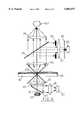
- FIG. 3shows a detailed diagrammatic side elevational view of a second embodiment of the present invention
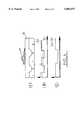
- FIGS. 4 (A) to (C)illustrate graphs of outputs from detectors D1 and D2 shown in FIG. 3;
- FIG. 5shows a schematic diagram of a control system of the embodiment of FIG. 4;
- FIG. 6shows a diagrammatic view of a third embodiment of the invention.
- FIG. 7shows a schematic diagram of a control system of the embodiment of FIG. 6.
- FIG. 1illustrates in simplified form a system which enables this to be achieved.
- the systemuses a circular disc 1 (although any other suitable shape of support substrate may be used) which comprises lower and upper layers of transparent plastic material 2,3 which provide the disc with smooth upper and lower surfaces. Sandwiched between the two plastic layers is a thin layer of metal 4 which provides a light reflecting surface.
- the plasticmay be of any suitable material such that the material to be optically analysed can be attached to the upper surface of the disc in the same way in which it would be attached to any conventional substrate.
- the appropriate antibodyis bound to the upper surface of the disc (this may require some pre-preparation of the surface).
- the surfaceis then exposed to the sample to be tested, e.g. blood plasma, in order to bind any antigens in the sample to the antibodies.
- the surfaceis then washed to remove any excess, unbound, material and exposed to the appropriate enzyme-conjugated antibodies 5 which attach to the bound antibodies.
- the bound enzymes 5can be visualised by reacting them with a substrate to produce a coloured precipitate. The precipitate presents a multiplicity of minute opaque patches over the upper surface of the disc. It will be apparent that the system is equally applicable to other types of assay which produce a colour, or other light interfering, change.
- the discis mounted on a rotatable shaft 6 which is driven by a drive means (not shown in FIG. 1) causing the disc to rotate.
- An optical block 7is mounted above the disc and is movable along a substantially linear track.
- the optical block 7comprises a laser diode 8 which produces a beam of coherent light 9 which is collimated and focused on to the surface of the disc 1 by a lens arrangement 10.
- the optical blockalso comprises a detector 11 for detecting light reflected from the surface of the metal layer within the disc.
- the lens arrangement 10includes a polarising prism 12 which allows only vertically polarised light to pass therethrough and a quarter waveplate (not shown) which causes light to be rotated by 45°.
- the discIn operation, the disc is rotated by the drive means relative to the optical block. With the block means stationary the light beam produced by the laser diode travels around a circular track of the disc. By moving the optical block along its linear track it is possible to scan the laser beam around any selected circular track of the disc. In areas of the disc surface where no light absorbing material is present, light passes through the upper plastic layer, is reflected from the metal layer, and travels back to the optical block, through the upper plastic layer. Light entering the optical block encounters first the quarter wavelength plate, which rotates the light by a further 45° , and then the polarising prism which, because the polarization of the reflected light has been rotated by 180° , causes the light to be redirected at right angles towards the detector.
- the detector 11is coupled to a data analysis and logging system which stores the output of the detector.
- This systemmay store the output as a continuous analogue signal or as discrete digital samples which represents a reduced resolution image of the surface. Assuming the latter, the sampling rate may be varied to fit the data storage capacity available.
- optical, mechanical and electrical means so far described for implementing an analyte detectorare substantially as conventionally used for reading data from compact discs.
- One such conventional systemis described in the text book ⁇ Digital Audio and Compact Disc Technology ⁇ , 2nd edition, Edited by Luc Baert et al (Sony Service Centre Europe), Newnes, 1994.
- the system of FIG. 1is adequate for obtaining an image of the disc surface, or a portion of that surface when the actual location of the portion itself is no significance. However, it may be desirable to be able to scan a selected area of the disc surface, for example where an ELISA has been carried out only in that region, or when it is desired to look again at a specific region of interest.
- Conventional compact discsencode digital information in an intermediate region of the disc by producing a series of perturbations 13 (e.g. bumps or pits) on the upper surface of a lower plastic layer 14 and subsequently coating this surface with a reflective layer 15 such as a thin layer of aluminium.
- the reflective layeris then covered with a layer of transparent plastic 16 which provides protection for the intermediate layer (FIG. 2).
- Position codescan be imprinted at discrete positions (e.g. every 2 to 3 ⁇ m or at any other appropriate interval) around that innermost track incrementing by one between each position. Similarly, the codes are incremented from track to track.
- address informationmay be distributed according to a track/sector arrangement in the same way in which servo-codes are encoded onto magnetic floppy and hard disks.
- the opticsare shown in FIG. 3 and which makes use of discs having address information digitally encoded and distributed over an intermediate layer as described above.
- This systemalso makes use of the fact that the reflective layer can be made to transmit a significant proportion of the incident light (e.g. 40%).
- the system of the second embodimentincludes a shaft (not shown) on which the disc 18 is mounted and which causes the disc to rotate and means for moving the optics along a linear track relative to the upper surface of the disc.
- the rotation and displacement meansare not shown in FIG. 2 for simplicity.
- the optical system of FIG. 3comprises a light source 19, which may be for example a semi-conductor laser or light emitting diode, arranged beneath the disc.
- the output beam 20 of the light sourceis directed up an optical axis 20a to a polarising prism (a beam splitter) 21 which allows only light of a given polarisation to pass, i.e. only the light received directly from the laser.
- the transmitted lightis then incident upon a first lens 22 which is arranged to focus light onto the lower surface 23 of the reflective layer within the disc.
- a fraction of the light incident upon the compact discis transmitted through the reflective layer and exits from the upper surface of the disc. Any material attached to the upper surface will interfere with light exiting the disc.
- Transmitted light which is not interfered withis received by a collimation lens 24, focused onto the upper surface of the disc, which directs the received light onto a partially transparent mirror 25 which in turn allows a fraction of the incident light to pass therethrough whilst causing the remainder to be reflected at right angles.
- Light passing directly through the partially transparent mirroris incident upon a further lens 26 which focuses the light onto the detection surface of a detector D2.
- Light reflected at right angles by the mirror 25is incident upon a lens 27 which focuses light onto a detector D3.
- a fraction of the light incident on the reflective layer within the discis reflected back towards the first lens 22 which acts as a collimation lens directing light back to the polarising prism 21.
- the reflected lightis now horizontally polarised and is reflected from the polarising prism at right angles to the optical axis. This reflected light is received by a fourth lens 28 which focuses received light onto a detector D1.
- Light reflected by the reflective layerwill be modulated with the information digitally encoded into the disc so that the output from the detector D1 will be similarly modulated. As this light does not exit from the upper surface of the disc it will not be interfered with by material attached to the upper sample support surface of the disc and address information can be determined from the output of D1 with minimal error.
- the optical block situated below the discalso incorporates tracking optics which enables the correct tracking of the disc tracks in a similar way to that used in conventional compact disc players.
- the tracking opticscomprise a diffraction grating which splits the output from the laser into three parallel beams which are subsequently focused by the first lens to provide three slightly spaced-apart spots. The spacing between these spots is such that when the central spot is directly over the centre of one track the other two spots lie on either side of that track.
- the detector D1actually comprises three adjacent detectors which receive reflected light and the spacing of which is equivalent to that between the beam spots. In order to align the laser correctly, the laser position is adjusted until the output from the centre detector is a maximum and the outputs from the two side detectors is a minimum. A feedback control system is used to maintain the correct tracking.
- the output provided by detector D2is modulated with the digital address information encoded onto the disc and, provided that no light absorbing material is attached to the upper surface of the disc, is substantially of the form of the output of detector D1, i.e. the ratio of the output signals of D1 and D2 will be constant. However, if light absorbing material is present on the upper surface of the disc this will interfere with light transmitted through the reflective layer and the output from detector D2 will drop whilst that from D1 will remain constant. The ratio of the output signals of D1 and D2 will change accordingly. If the material attached to the surface of the disc is reflective, e.g. gold labelled, the output of D1 will rise whilst that of D2 will fall when the light beam scans the material. The ratio of D1 to D2 will indicate the presence of such material.
- FIG. 4illustrates the case where the bound material is absorbent but not reflective and shows at (A) a cross-section taken through typical disc to the surface of which a stained cell 29 is attached.
- the reflective layer beneath the support surfaceis encoded with the digital address 10101.
- the ratio between the output signals of detectors D1 and D2(FIG. 4B) remains constant where the upper surface is not covered by the cell.
- the signal produced by detector D2falls so that the ratio (FIG. 4C) of the signals produced by D1 and D2 similarly drops.
- FIG. 5shows a block diagram of a system for controlling the embodiment of FIG. 3 with the flow of data through the system being indicated by arrows.
- the analogue outputs from detectors D1 and D2are received by an integrated circuit 30 which determines the ratio of the two outputs. This ratio is then converted to digital form by an analogue to digital converter 31 and transmitted to a bitstream generator 34 for compression using bitstream modulation.
- the output from detector D1which represents the digitally encoded address information, is also transmitted to an address bitstream generator 33 for compression.
- the two channel bitstream datais received by a bitstream merge and display unit which processes the data for storage and for display.
- the detector D3is provided (although this is optional) which receives light from the partially transparent mirror through an aperture 53, lens 27 and pinhole arrangement 35. This arrangement effectively reduces the area of the disc surface from which light is received by the detector D3 and also reduces the depth of focus. If the output of detector D2, or the ratio D1: D2, exceeds a predetermined threshold the output of detector D3 can be used to increase the resolution with which the surface of the disc is viewed. The use of detectors D2 and D3 in combination prevents the likelihood of the detector D3 producing errors if the system used only detector D3. D3 may alternatively provide a second type of detector for detecting for example fluorescent light emitted by material attached to the surface of the disc.
- FIG. 6shows a further embodiment of the invention in which absolute position information can be determined, although the accuracy of this information may be somewhat less then that provided by the embodiment of FIGS. 4 and 5.
- the disc constructionis considerably simplified.
- the optical inspection systemhas a ⁇ U ⁇ shaped arm 36 with a light source 52 and a detector 38 attached to the upper and lower ends of the arm respectively.
- the source and detectorare connected to a laser controller 39 and a buffer 40, the latter being arranged to transfer detected signal data to a personal computer 41 via an analogue to digital converter 42 and a data store 43.
- the disc 44 upon which the sample to be inspected is attached or supportedis mounted on a rotatable spindle 45 which lies parallel to the bight of 46 of the arm 36.
- the spindle 45is driven by a spindle motor 47.
- the optical axes of the light source 37 and detector 38are aligned with one another along the axis A--A.
- the arm 36is coupled to a stepper motor 48 which precisely rotates the arm in a plane parallel to the plane of the disc 44 such that, in combination, rotation of the arm and of the disc allows the light source/detector arrangement to be scanned across the entire useable surface of the disc.
- the stepper motor 48is controlled by a motion controller 49, which in turn is controlled by the computer 41, such that the relative position of the spindle 45 can be determined to within an accuracy of 6 ⁇ m.
- the discis of a completely transparent material but is provided with a black bar 50 around a portion of its upper peripheral surface.
- the bar 50acts as an angular calibration marking for the inspection system.
- the armWhen the edge of the disc is detected, the arm is held stationary until the calibration marking 50 interrupts the beam.
- the leading edge of the marking 50provides an origin to which the angular position of the detector can be referenced whilst the edge of the disc provides an origin for the radial position. Due to the accuracy of the stepper motor 48 and the spindle motor 47, it is then possible to precisely determine the position of the light source/detector arrangement relative to the disc.
- the disc 44comprises a plurality of wells or indentations 51 formed in its upper surface.
- the wellscontain the sample to be inspected and are filled, for example, by microtitration.
- the personal computermay be arranged to step the light source/detector arrangement over the disc surface from one well to another. This is enabled by the precise position information obtained from the calibration marking and the disc edge.
- FIG. 7shows a flow diagram of the control process for this system.
- the system of FIG. 6may be modified so that the light source 52 and the detector 38 are both arranged on the same side of the disc, with the disc being provided with a reflective coating on or beneath the surface on which the sample is supported. In this arrangement the detector detects light reflected from the reflective coating.
- the two main advantages of the arrangementare that the surface of the disc which does not support the sample may be safely handled, as it does not lie in the light transmission path, and that the signal to noise ratio of the optical inspection process may be increased because light will have to pass through a sample twice in travelling from the source to the detector.
- the support surface of the discmay be scanned with infra-red or ultra-violet radiation rather than visible light. It is also possible to scan the surface with radiation which excites fluorescence in material attached to the surface and to use the detector (D2 or D3) arrangement to detect light at the emission wavelength.
- the discin such a way that the support surface is internal to the disc and is not the upper surface of the disc. This may provide the advantages that the sample is not damaged by handling and that a precise volume of sample may be analysed.
- an appropriate gelmay be provided on the upper surface of the disc. Electrodes for applying a potential across the gel may be formed integrally therewith or may be printed, or otherwise deposited, on the upper surface. The electrodes may be spaced radially or circumferentially. Pits may be provided in the gel into which the material to be run can be placed.
- a preferred form of arrayis a linear array extending radially with respect to the disc.
- the light sourcewould take the form of a laser line generator arranged to generate a radially extending line of light aligned with the diode array. Some degree of optical magnification may be incorporated between the source and the generator to allow the resolution of the system to be varied. After each rotation of the disc, the source/detector arrangement would be stepped inwardly by the length of the laser line. The advantages of this arrangement are higher speed and higher resolution.
Landscapes
- Chemical & Material Sciences (AREA)
- Physics & Mathematics (AREA)
- Immunology (AREA)
- Life Sciences & Earth Sciences (AREA)
- Analytical Chemistry (AREA)
- Biochemistry (AREA)
- General Health & Medical Sciences (AREA)
- General Physics & Mathematics (AREA)
- Health & Medical Sciences (AREA)
- Pathology (AREA)
- Chemical Kinetics & Catalysis (AREA)
- Spectroscopy & Molecular Physics (AREA)
- Investigating Or Analysing Materials By Optical Means (AREA)
- Investigating, Analyzing Materials By Fluorescence Or Luminescence (AREA)
- Automatic Analysis And Handling Materials Therefor (AREA)
- Investigating Or Analysing Biological Materials (AREA)
- Optical Measuring Cells (AREA)
- Analysing Materials By The Use Of Radiation (AREA)
- Investigating Or Analysing Materials By The Use Of Chemical Reactions (AREA)
Abstract
Description
Claims (3)
Priority Applications (4)
| Application Number | Priority Date | Filing Date | Title |
|---|---|---|---|
| US09/156,475US6256088B1 (en) | 1994-09-21 | 1998-09-18 | Apparatus and method for carrying out analysis of samples |
| US09/643,030US6339473B1 (en) | 1994-09-21 | 2000-08-21 | Apparatus and method for carrying out analysis of samples |
| US09/991,863US7110094B2 (en) | 1994-09-21 | 2001-11-16 | Apparatus and method for carrying out analysis of samples using radiation detector output ratios |
| US09/991,429US6992769B2 (en) | 1994-09-21 | 2001-11-16 | Apparatus and method for carrying out analysis of samples using semi-reflective beam radiation inspection |
Applications Claiming Priority (3)
| Application Number | Priority Date | Filing Date | Title |
|---|---|---|---|
| GB9418981 | 1994-09-21 | ||
| GB9418981AGB9418981D0 (en) | 1994-09-21 | 1994-09-21 | Apparatus and method for carrying out analysis of samples |
| PCT/GB1995/002186WO1996009548A1 (en) | 1994-09-21 | 1995-09-15 | Apparatus and method for carrying out analysis of samples |
Related Parent Applications (2)
| Application Number | Title | Priority Date | Filing Date |
|---|---|---|---|
| PCT/GB1995/002186ContinuationWO1996009548A1 (en) | 1994-09-21 | 1995-09-15 | Apparatus and method for carrying out analysis of samples |
| PCT/GB1995/002186A-371-Of-InternationalWO1996009548A1 (en) | 1994-09-21 | 1995-09-15 | Apparatus and method for carrying out analysis of samples |
Related Child Applications (1)
| Application Number | Title | Priority Date | Filing Date |
|---|---|---|---|
| US09/156,475ContinuationUS6256088B1 (en) | 1994-09-21 | 1998-09-18 | Apparatus and method for carrying out analysis of samples |
Publications (1)
| Publication Number | Publication Date |
|---|---|
| US5892577Atrue US5892577A (en) | 1999-04-06 |
Family
ID=10761649
Family Applications (6)
| Application Number | Title | Priority Date | Filing Date |
|---|---|---|---|
| US08/809,402Expired - Fee RelatedUS5892577A (en) | 1994-09-21 | 1995-09-15 | Apparatus and method for carrying out analysis of samples |
| US09/156,475Expired - Fee RelatedUS6256088B1 (en) | 1994-09-21 | 1998-09-18 | Apparatus and method for carrying out analysis of samples |
| US09/643,030Expired - Fee RelatedUS6339473B1 (en) | 1994-09-21 | 2000-08-21 | Apparatus and method for carrying out analysis of samples |
| US09/642,996Expired - Fee RelatedUS6803999B1 (en) | 1994-09-21 | 2000-08-21 | Analytical disc with optically trackable encoded information and related optical inspection system |
| US09/665,481Expired - Fee RelatedUS6476907B1 (en) | 1994-09-21 | 2000-09-20 | Apparatus and method for carrying out histological analysis of specimens |
| US09/991,863Expired - Fee RelatedUS7110094B2 (en) | 1994-09-21 | 2001-11-16 | Apparatus and method for carrying out analysis of samples using radiation detector output ratios |
Family Applications After (5)
| Application Number | Title | Priority Date | Filing Date |
|---|---|---|---|
| US09/156,475Expired - Fee RelatedUS6256088B1 (en) | 1994-09-21 | 1998-09-18 | Apparatus and method for carrying out analysis of samples |
| US09/643,030Expired - Fee RelatedUS6339473B1 (en) | 1994-09-21 | 2000-08-21 | Apparatus and method for carrying out analysis of samples |
| US09/642,996Expired - Fee RelatedUS6803999B1 (en) | 1994-09-21 | 2000-08-21 | Analytical disc with optically trackable encoded information and related optical inspection system |
| US09/665,481Expired - Fee RelatedUS6476907B1 (en) | 1994-09-21 | 2000-09-20 | Apparatus and method for carrying out histological analysis of specimens |
| US09/991,863Expired - Fee RelatedUS7110094B2 (en) | 1994-09-21 | 2001-11-16 | Apparatus and method for carrying out analysis of samples using radiation detector output ratios |
Country Status (11)
| Country | Link |
|---|---|
| US (6) | US5892577A (en) |
| EP (2) | EP0782705B8 (en) |
| JP (4) | JP3364719B2 (en) |
| CN (2) | CN1163752C (en) |
| AT (1) | ATE314649T1 (en) |
| AU (1) | AU714662B2 (en) |
| BR (1) | BR9509021A (en) |
| CA (2) | CA2200562C (en) |
| DE (1) | DE69534719T2 (en) |
| GB (1) | GB9418981D0 (en) |
| WO (1) | WO1996009548A1 (en) |
Cited By (138)
| Publication number | Priority date | Publication date | Assignee | Title |
|---|---|---|---|---|
| US6024920A (en)* | 1998-04-21 | 2000-02-15 | Bio-Rad Laboratories, Inc. | Microplate scanning read head |
| US6196979B1 (en) | 1998-08-24 | 2001-03-06 | Burstein Technologies, Inc. | Cassette and applicator for biological and chemical sample collection |
| US6256088B1 (en)* | 1994-09-21 | 2001-07-03 | University Court Of The University Of Glasgow, The | Apparatus and method for carrying out analysis of samples |
| US6312901B2 (en) | 1996-07-08 | 2001-11-06 | Burstein Technologies, Inc. | Spatially addressable, cleavable reflective signal elements, assay device and method |
| US6327031B1 (en) | 1998-09-18 | 2001-12-04 | Burstein Technologies, Inc. | Apparatus and semi-reflective optical system for carrying out analysis of samples |
| US6331275B1 (en) | 1996-07-08 | 2001-12-18 | Burstein Technologies, Inc. | Spatially addressable, cleavable reflective signal elements, assay device and method |
| US6338968B1 (en) | 1998-02-02 | 2002-01-15 | Signature Bioscience, Inc. | Method and apparatus for detecting molecular binding events |
| US6342349B1 (en) | 1996-07-08 | 2002-01-29 | Burstein Technologies, Inc. | Optical disk-based assay devices and methods |
| US20020018199A1 (en)* | 1999-11-04 | 2002-02-14 | Martin Blumenfeld | Imaging of biological samples using electronic light detector |
| US6368795B1 (en) | 1998-02-02 | 2002-04-09 | Signature Bioscience, Inc. | Bio-assay device and test system for detecting molecular binding events |
| US20020058242A1 (en)* | 1996-09-20 | 2002-05-16 | James Paul Demers | Spatially addressable combinatorial chemical arrays in cd-rom format |
| US6395480B1 (en) | 1999-02-01 | 2002-05-28 | Signature Bioscience, Inc. | Computer program and database structure for detecting molecular binding events |
| US20020066069A1 (en)* | 2000-10-18 | 2002-05-30 | Sony Corporation | Method for mask data verification and computer readable record medium recording the verification program |
| US20020071359A1 (en)* | 2000-12-08 | 2002-06-13 | Worthington Mark Oscar | Methods for detecting analytes using optical discs and optical disc readers |
| US20020076354A1 (en)* | 2000-12-01 | 2002-06-20 | Cohen David Samuel | Apparatus and methods for separating components of particulate suspension |
| US20020098528A1 (en)* | 2000-11-17 | 2002-07-25 | Gordon John F. | Methods and apparatus for blood typing with optical bio-disc |
| WO2002059622A1 (en)* | 2000-11-17 | 2002-08-01 | Burstein Technologies, Inc. | Methods and apparatus for blood typing with optical bio-discs |
| US20020106661A1 (en)* | 1996-07-08 | 2002-08-08 | Burstein Laboratories, Inc. | Optical disk-based assay devices and methods |
| US20020122364A1 (en)* | 2000-11-09 | 2002-09-05 | Worthington Mark Oscar | Disc drive system and methods for use with bio-discs |
| WO2002046721A3 (en)* | 2000-12-08 | 2002-09-19 | Burstein Technologies Inc | Optical discs for measuring analytes |
| US20020163642A1 (en)* | 2000-11-16 | 2002-11-07 | Zoval Jim V. | Optical biodiscs with reflective layers |
| US20020168663A1 (en)* | 2001-02-27 | 2002-11-14 | Phan Brigitte Chau | Methods for DNA conjugation onto solid phase including related optical biodiscs and disc drive systems |
| US20020172980A1 (en)* | 2000-11-27 | 2002-11-21 | Phan Brigitte Chau | Methods for decreasing non-specific binding of beads in dual bead assays including related optical biodiscs and disc drive systems |
| US20020171838A1 (en)* | 2001-05-16 | 2002-11-21 | Pal Andrew Attila | Variable sampling control for rendering pixelization of analysis results in a bio-disc assembly and apparatus relating thereto |
| US20020176342A1 (en)* | 2001-01-11 | 2002-11-28 | Worthington Mark Oscar | Optical disc analysis system including related methods for biological and medical imaging |
| US20020196435A1 (en)* | 2000-11-22 | 2002-12-26 | Cohen David Samuel | Apparatus and methods for separating agglutinants and disperse particles |
| US20030003464A1 (en)* | 2000-11-27 | 2003-01-02 | Phan Brigitte C. | Dual bead assays including optical biodiscs and methods relating thereto |
| US20030035352A1 (en)* | 2001-07-12 | 2003-02-20 | Worthington Mark Oscar | Optical disc system and related detecting methods for analysis of microscopic structures |
| US20030053047A1 (en)* | 2001-08-28 | 2003-03-20 | Tosoh Corporation | Information measuring apparatus using a fine channel device |
| US20030054563A1 (en)* | 2001-09-17 | 2003-03-20 | Gyros Ab | Detector arrangement for microfluidic devices |
| US20030064872A1 (en)* | 2001-07-20 | 2003-04-03 | Worthington Mark Oscar | Optical analysis disc and related drive assembly for performing interactive centrifugation |
| US20030096324A1 (en)* | 2001-09-12 | 2003-05-22 | Mikhail Matveev | Methods for differential cell counts including related apparatus and software for performing same |
| US20030096434A1 (en)* | 2001-07-12 | 2003-05-22 | Krutzik Siegfried Richard | Multi-purpose optical analysis optical bio-disc for conducting assays and various reporting agents for use therewith |
| NL1019446C2 (en)* | 2001-11-28 | 2003-06-02 | Ibis Technologies B V | Support for use in assay of a particle in a sample, comprises a surface suitable for receiving a microbead and inspection by an optical technique, where the microbead is suitable for binding a specific type of particle |
| NL1019875C2 (en)* | 2001-11-28 | 2003-06-02 | Ibis Technologies B V | Support for use in determining particles in a sample and method for manufacturing such a support, and method for determining particles in a sample. |
| US20030104486A1 (en)* | 2000-11-16 | 2003-06-05 | Selvan Gowri Pyapali | Methods and apparatus for detecting and quantifying lymphocytes with optical biodiscs |
| US20030113925A1 (en)* | 2001-09-07 | 2003-06-19 | Gordon John Francis | Nuclear morphology based identification and quantification of white blood cell types using optical bio-disc systems |
| US20030129665A1 (en)* | 2001-08-30 | 2003-07-10 | Selvan Gowri Pyapali | Methods for qualitative and quantitative analysis of cells and related optical bio-disc systems |
| WO2002068696A3 (en)* | 2001-02-27 | 2003-08-14 | Burstein Technologies Inc | Methods for dna conjugation onto solid phase including related optical biodiscs and disc drive systems |
| US20030156763A1 (en)* | 2001-12-31 | 2003-08-21 | Gyros Ab. | Method and arrangement for reducing noise |
| US6625336B2 (en) | 1998-10-16 | 2003-09-23 | Imation Corp. | Optical sensor having dielectric film stack |
| US6630108B1 (en)* | 1998-10-08 | 2003-10-07 | Maxmat Sa | Optical measuring head, in particular for automatic chemical or biological reaction analyzer |
| US20030190673A1 (en)* | 2000-05-11 | 2003-10-09 | Nikitin Petr Ivanovich | Method for optical detection of an adjoining of a material component to a sensor material with the aid of biological, chemical or physical interaction and device for carrying out said method (variants) |
| US20030193666A1 (en)* | 2002-04-11 | 2003-10-16 | Nanophotonics Ag | Device for measuring surface defects |
| US20030215938A1 (en)* | 2002-05-16 | 2003-11-20 | Sandell Donald R. | Lens assembly for biological testing |
| US6653152B2 (en) | 1997-11-19 | 2003-11-25 | Imation Corp. | Sensor disk having radial grooves and optical assaying method using same |
| US20030219713A1 (en)* | 2001-11-20 | 2003-11-27 | Valencia Ramoncito Magpantay | Optical bio-discs and fluidic circuits for analysis of cells and methods relating thereto |
| US20030230383A1 (en)* | 2001-07-24 | 2003-12-18 | Glenn Sasaki | Method and apparatus for bonded fluidic circuit for optical bio-disc |
| US20030231312A1 (en)* | 2002-04-08 | 2003-12-18 | Jan Sjoberg | Homing process |
| US6685885B2 (en)* | 2001-06-22 | 2004-02-03 | Purdue Research Foundation | Bio-optical compact dist system |
| WO2003043403A3 (en)* | 2001-11-19 | 2004-02-26 | Burstein Technologies Inc | Methods and apparatus for blood typing with optical bio-discs |
| US20040071332A1 (en)* | 2002-10-15 | 2004-04-15 | Xerox Corporation | Apparatus and method for detecting and locating rare cells |
| US20040109163A1 (en)* | 2001-02-28 | 2004-06-10 | Spectrx, Inc. | System and method for measurement and analysis of a sample by absorption spectrophotometry |
| US20040131241A1 (en)* | 2002-10-15 | 2004-07-08 | Curry Douglas N. | Method of converting rare cell scanner image coordinates to microscope coordinates using reticle marks on a sample media |
| US20040166593A1 (en)* | 2001-06-22 | 2004-08-26 | Nolte David D. | Adaptive interferometric multi-analyte high-speed biosensor |
| US20040224421A1 (en)* | 2000-06-15 | 2004-11-11 | Deweerd Herman | Bi-directional scanning method |
| US20040241381A1 (en)* | 2002-01-31 | 2004-12-02 | Chen Yihfar | Microfluidic structures with circumferential grooves for bonding adhesives and related optical analysis discs |
| US20040248093A1 (en)* | 2000-11-27 | 2004-12-09 | Coombs James Howard | Magneto-optical bio-discs and systems including related methods |
| US20040264323A1 (en)* | 2002-01-28 | 2004-12-30 | Worthington Mark Oscar | Methods and apparatus for logical triggering |
| EP1229329A4 (en)* | 1999-11-05 | 2005-01-05 | Takara Bio Inc | Bases having ligands immobilized thereon |
| WO2005001766A1 (en)* | 2003-06-30 | 2005-01-06 | Gyros Patent Ab | Confidence determination |
| US20050003459A1 (en)* | 2002-01-30 | 2005-01-06 | Krutzik Siegfried Richard | Multi-purpose optical analysis disc for conducting assays and related methods for attaching capture agents |
| US20050002827A1 (en)* | 2002-01-29 | 2005-01-06 | Mcintyre Kevin Robert | Optical discs including equi-radial and/or spiral analysis zones and related disc drive systems and methods |
| US20050014249A1 (en)* | 2003-02-21 | 2005-01-20 | Norbert Staimer | Chromatographic analysis on optical bio-discs and methods relating thereto |
| US20050023765A1 (en)* | 2002-01-31 | 2005-02-03 | Coombs James Howard | Bio-safety features for optical analysis disc and disc system including same |
| US20050032126A1 (en)* | 2003-03-03 | 2005-02-10 | Coombs James H. | Methods and apparatus for use in detection and quantitation of various cell types and use of optical bio-disc for performing same |
| US20050032052A1 (en)* | 2002-01-14 | 2005-02-10 | Pal Andrew Attila | Methods and apparatus for extracting data from and optical analysis disc |
| US20050037484A1 (en)* | 2003-04-23 | 2005-02-17 | Norbert Staimer | Optical bio-discs including spiral fluidic circuits for performing assays |
| US20050047968A1 (en)* | 2003-06-19 | 2005-03-03 | Horacio Kido | Fluidic circuits for sample preparation including bio-discs and methods relating thereto |
| US20050053260A1 (en)* | 1999-08-23 | 2005-03-10 | Worthington Mark O. | Methods and apparatus for analyzing operational and analyte data acquired from optical discs |
| WO2005009581A3 (en)* | 2003-07-15 | 2005-03-24 | Nagaoka Kk | Methods and apparatus for blood separation and analysis using membranes on an optical bio-disc |
| US20050069923A1 (en)* | 1996-07-08 | 2005-03-31 | Mullis Kary Banks | Dual bead assays using cleavable spacers and/or ligation to improve specificity and sensitivity including related methods and apparatus |
| US20050084422A1 (en)* | 2003-06-19 | 2005-04-21 | Horacio Kido | Fluidic circuits for sample preparation including bio-discs and methods relating thereto |
| US20050084974A1 (en)* | 2003-10-15 | 2005-04-21 | Lighthouse Instruments, Llc. | System and method for automated headspace analysis |
| US20050111001A1 (en)* | 2003-11-24 | 2005-05-26 | General Electric Company | Sensor systems and methods for remote quantification of compounds |
| US20050111000A1 (en)* | 2003-11-24 | 2005-05-26 | Potyrailo Radislav A. | Sensor systems and methods for quantification of physical parameters, chemical and biochemical volatile and nonvolatile compounds in fluids |
| US20050111342A1 (en)* | 2003-11-24 | 2005-05-26 | Wisnudel Marc B. | Authenticable optical disc, system for authenticating an optical disc and method thereof |
| US20050109396A1 (en)* | 2002-12-04 | 2005-05-26 | Piero Zucchelli | Devices and methods for programmable microscale manipulation of fluids |
| US20050112358A1 (en)* | 2003-11-24 | 2005-05-26 | Potyrailo Radislav A. | Methods for deposition of sensor regions onto optical storage media substrates and resulting devices |
| US20050111328A1 (en)* | 2003-11-24 | 2005-05-26 | General Electric Company | Sensor system and methods for improved quantitation of environmental parameters |
| US20050130325A1 (en)* | 2003-12-12 | 2005-06-16 | Hitachi Software Engineering Co., Ltd. | Fluorescent beads detecting method and fluorescent beads detecting apparatus |
| US20050176059A1 (en)* | 2002-01-31 | 2005-08-11 | Pal Andrew A. | Bio-safe dispenser and optical analysis disc assembly |
| US20050185569A1 (en)* | 2002-01-31 | 2005-08-25 | Coombs James H. | Method for triggering through disc grooves and related optical analysis discs and system |
| US20050185175A1 (en)* | 2002-07-16 | 2005-08-25 | Canos Avelino C. | Rotary support and apparatus used for the multiple spectroscopic characterisation of samples of solid materials |
| US20050214827A1 (en)* | 1996-07-08 | 2005-09-29 | Burstein Technologies, Inc. | Assay device and method |
| US20050221048A1 (en)* | 2002-01-31 | 2005-10-06 | James Rodney Norton | Manufacturing processes for making optical analysis discs including successive patterning operations and optical discs thereby manufactured |
| US20050236481A1 (en)* | 2004-04-21 | 2005-10-27 | General Electric Company | Authentication system, data device, and methods for using the same |
| US20050244953A1 (en)* | 2004-04-30 | 2005-11-03 | Kimberly-Clark Worldwide, Inc. | Techniques for controlling the optical properties of assay devices |
| US20050244952A1 (en)* | 2004-04-30 | 2005-11-03 | Kimberly-Clark Worldwide, Inc. | Electroluminescent illumination source for optical detection systems |
| US20060006344A1 (en)* | 2002-05-16 | 2006-01-12 | Applera Corporation | Achromatic lens array |
| US20060019265A1 (en)* | 2004-04-30 | 2006-01-26 | Kimberly-Clark Worldwide, Inc. | Transmission-based luminescent detection systems |
| US20060041898A1 (en)* | 2003-11-24 | 2006-02-23 | Radislav Potyrailo | Media drive with a luminescence detector and methods of detecting an authentic article |
| WO2006024109A1 (en)* | 2004-09-03 | 2006-03-09 | Newsouth Innovations Pty Limited | Rotatable objects and systems and methods for determining the position of at least one sample on a rotatable object |
| US7033747B2 (en) | 2001-04-11 | 2006-04-25 | Nagaoka & Co., Ltd | Multi-parameter assays including analysis discs and methods relating thereto |
| US20060132878A1 (en)* | 2004-12-20 | 2006-06-22 | Palo Alto Research Center Incorporated | Method of scanning and light collection for a rare cell detector |
| US20060132778A1 (en)* | 2004-12-21 | 2006-06-22 | Palo Alto Research Center Incorporated | Time-multiplexed scanning light source for multi-probe, multi-laser fluorescence detection systems |
| US7088650B1 (en) | 1999-08-23 | 2006-08-08 | Worthington Mark O | Methods and apparatus for optical disc data acquisition using physical synchronization markers |
| US20060182329A1 (en)* | 2003-03-24 | 2006-08-17 | Ryosuke Yamada | Analysis device and method for cell count in the analysis device |
| US20060256350A1 (en)* | 2005-02-01 | 2006-11-16 | David Nolte | Laser scanning interferometric surface metrology |
| US20060275840A1 (en)* | 2000-11-10 | 2006-12-07 | Ge Healthcare Limited | Support and method for cell based assays |
| US20070003925A1 (en)* | 2005-02-01 | 2007-01-04 | Nolte David D | Multiplexed biological analyzer planar array apparatus and methods |
| US20070121113A1 (en)* | 2004-12-22 | 2007-05-31 | Cohen David S | Transmission-based optical detection systems |
| US20070146715A1 (en)* | 2003-11-24 | 2007-06-28 | General Electric Company | Sensor systems for quantification of physical parameters, chemical and biochemical volatile and nonvolatile compounds in fluids |
| US20070166721A1 (en)* | 2003-06-27 | 2007-07-19 | Phan Brigitte C | Fluidic circuits, methods and apparatus for use of whole blood samples in colorimetric assays |
| US20070259366A1 (en)* | 2006-05-03 | 2007-11-08 | Greg Lawrence | Direct printing of patterned hydrophobic wells |
| US20070274863A1 (en)* | 2003-07-25 | 2007-11-29 | Horacio Kido | Fluidic circuits for sample preparation including bio-discs and methods relating thereto |
| US20080094974A1 (en)* | 2001-11-09 | 2008-04-24 | Burstein Technologies, Inc. | Optical disc system and related detecting methods for analysis of microscopic structures |
| US20080129981A1 (en)* | 2006-11-30 | 2008-06-05 | David D Nolte | Molecular interferometric imaging process and apparatus |
| US20080144899A1 (en)* | 2006-11-30 | 2008-06-19 | Manoj Varma | Process for extracting periodic features from images by template matching |
| US20080186477A1 (en)* | 2007-01-19 | 2008-08-07 | Xuefeng Wang | System with extended range of molecular sensing through integrated multi-modal data acquisition |
| US20080230605A1 (en)* | 2006-11-30 | 2008-09-25 | Brian Weichel | Process and apparatus for maintaining data integrity |
| US20080304073A1 (en)* | 2007-03-26 | 2008-12-11 | Nolte David D | Method and apparatus for conjugate quadrature interferometric detection of an immunoassay |
| US20090263913A1 (en)* | 2005-02-01 | 2009-10-22 | Nolte David D | Differentially encoded biological analyzer planar array apparatus and methods |
| US20090312195A1 (en)* | 2006-10-13 | 2009-12-17 | Eliseev Alexey V | Methods and microarrays compatible with dual functionality optical drives |
| US7796266B2 (en) | 2004-04-30 | 2010-09-14 | Kimberly-Clark Worldwide, Inc. | Optical detection system using electromagnetic radiation to detect presence or quantity of analyte |
| EP1775592A4 (en)* | 2004-07-12 | 2012-05-09 | Arkray Inc | Analyzer, method for specifying reaction vessel in analyzer, and analytical apparatus |
| US8362446B1 (en)* | 1998-10-01 | 2013-01-29 | 2C A/S | Apparatus for determining the position of an object |
| US20140133702A1 (en)* | 2010-10-26 | 2014-05-15 | California Institute Of Technology | Methods for Rapid Distinction between Debris and Growing Cells |
| US20140303006A1 (en)* | 2001-08-24 | 2014-10-09 | Applied Biosystems, Llc | Sequencing System with Memory |
| US20140315206A1 (en)* | 2008-04-04 | 2014-10-23 | Life Technologies Corporation | Scanning System and Method for Imaging and Sequencing |
| US9036153B1 (en)* | 2013-08-30 | 2015-05-19 | Google Inc. | Instrument for reflectivity measurement |
| US20150244932A1 (en)* | 2014-02-21 | 2015-08-27 | Samsung Electronics Co., Ltd. | Test apparatus and control method thereof |
| US9128056B2 (en) | 2012-03-29 | 2015-09-08 | Panasonic Intellectual Property Management Co., Ltd. | Sample holding carrier, and fluorescence detection system and fluorescence detection device that use same |
| US20150360225A1 (en)* | 2010-06-04 | 2015-12-17 | Sandia Corporation | Microfluidic devices, systems, and methods for quantifying particles using centrifugal force |
| US9343494B2 (en) | 2011-03-03 | 2016-05-17 | California Institute Of Technology | Light guided pixel configured for emissions detection and comprising a guide layer with a wavelength selective filter material and a light detector layer |
| US9426429B2 (en) | 2010-10-26 | 2016-08-23 | California Institute Of Technology | Scanning projective lensless microscope system |
| US9470633B2 (en)* | 2014-02-14 | 2016-10-18 | Google Inc. | Method, apparatus and system for transmittance measurement |
| US9643184B2 (en) | 2010-10-26 | 2017-05-09 | California Institute Of Technology | e-Petri dishes, devices, and systems having a light detector for sampling a sequence of sub-pixel shifted projection images |
| US9743020B2 (en) | 2010-03-23 | 2017-08-22 | California Institute Of Technology | Super resolution optofluidic microscopes for 2D and 3D imaging |
| US9766230B1 (en) | 2014-11-18 | 2017-09-19 | National Technology & Engineering Solutions Of Sandia, Llc | System and method for detecting components of a mixture including a valving scheme for competition assays |
| US9795961B1 (en) | 2010-07-08 | 2017-10-24 | National Technology & Engineering Solutions Of Sandia, Llc | Devices, systems, and methods for detecting nucleic acids using sedimentation |
| US9903001B1 (en) | 2012-07-19 | 2018-02-27 | National Technology & Engineering Solutions Of Sandia, Llc | Quantitative detection of pathogens in centrifugal microfluidic disks |
| US10024849B2 (en) | 2012-03-16 | 2018-07-17 | National Technology & Engineering Solutions Of Sandia, Llc | Systems, devices, and methods for agglutination assays using sedimentation |
| US10254298B1 (en) | 2015-03-25 | 2019-04-09 | National Technology & Engineering Solutions Of Sandia, Llc | Detection of metabolites for controlled substances |
| US10406528B1 (en) | 2016-08-04 | 2019-09-10 | National Technology & Engineering Solutions Of Sandia, Llc | Non-contact temperature control system for microfluidic devices |
| US10590477B2 (en) | 2013-11-26 | 2020-03-17 | National Technology & Engineering Solutions Of Sandia, Llc | Method and apparatus for purifying nucleic acids and performing polymerase chain reaction assays using an immiscible fluid |
| US10786811B1 (en) | 2016-10-24 | 2020-09-29 | National Technology & Engineering Solutions Of Sandia, Llc | Detection of active and latent infections with microfluidic devices and systems thereof |
| US10981174B1 (en) | 2016-08-04 | 2021-04-20 | National Technology & Engineering Solutions Of Sandia, Llc | Protein and nucleic acid detection for microfluidic devices |
Families Citing this family (73)
| Publication number | Priority date | Publication date | Assignee | Title |
|---|---|---|---|---|
| GB9620934D0 (en)* | 1996-10-08 | 1996-11-27 | Molecular Drives Limited | Multi-well containers |
| DE19707226A1 (en)* | 1997-02-24 | 1998-08-27 | Bodenseewerk Perkin Elmer Co | Light scanner |
| PL335482A1 (en)* | 1997-02-28 | 2000-04-25 | Burstein Lab | Laboratory in an optical disk |
| US5922617A (en)* | 1997-11-12 | 1999-07-13 | Functional Genetics, Inc. | Rapid screening assay methods and devices |
| IL136978A0 (en)* | 1997-12-30 | 2001-06-14 | Remacle Jose | Method comprising capture molecule fixed on disc surface |
| US20020177144A1 (en)* | 1997-12-30 | 2002-11-28 | Jose Remacle | Detection and/or quantification method of a target molecule by a binding with a capture molecule fixed on the surface of a disc |
| FR2784189B3 (en)* | 1998-10-05 | 2000-11-03 | Commissariat Energie Atomique | BIOCHIP AND DEVICE FOR READING A BIOCHIP COMPRISING A PLURALITY OF MOLECULAR RECOGNITION AREAS |
| JP2000121559A (en)* | 1998-10-14 | 2000-04-28 | Hitachi Denshi Ltd | Micropoint light quantity reading device |
| KR20010092427A (en)* | 1998-10-30 | 2001-10-24 | 번스타인 리차드 | Trackable optical discs with concurrently readable analyte material |
| EP1145009B1 (en)* | 1999-02-03 | 2004-05-06 | Europäisches Laboratorium Für Molekularbiologie (Embl) | Method of detecting analytes in a sample and support for this purpose |
| US6503359B2 (en) | 1999-03-05 | 2003-01-07 | Burstein Technologies, Inc. | Monomolecular adhesion methods for manufacturing microfabricated multilaminate devices |
| WO2001084126A2 (en)* | 2000-04-28 | 2001-11-08 | Electro Scientific Industries, Inc. | Directional lighting and method to distinguish three dimensional information |
| US6937323B2 (en) | 2000-11-08 | 2005-08-30 | Burstein Technologies, Inc. | Interactive system for analyzing biological samples and processing related information and the use thereof |
| US6760298B2 (en) | 2000-12-08 | 2004-07-06 | Nagaoka & Co., Ltd. | Multiple data layer optical discs for detecting analytes |
| US7054258B2 (en) | 2000-12-08 | 2006-05-30 | Nagaoka & Co., Ltd. | Optical disc assemblies for performing assays |
| WO2003010563A2 (en)* | 2001-07-24 | 2003-02-06 | Burstein Technologies, Inc. | Magnetic assisted detection of magnetic beads using optical disc drives |
| WO2003036337A2 (en)* | 2001-10-24 | 2003-05-01 | Burstein Technologies, Inc. | Optical biological disk analyser |
| AU2002359227A1 (en)* | 2001-12-31 | 2003-07-15 | Gyros Ab | Method and arrangement for reducing noise in a microfluid device |
| FR2835615B1 (en)* | 2002-02-07 | 2004-09-17 | Antonios Vekris | DEVICE FOR ANALYZING A MOLECULE BY MEANS OF A FLUID COMING INTO CONTACT WITH A SUPPORT CARRYING A MOLECULE |
| FR2835614A1 (en)* | 2002-02-07 | 2003-08-08 | Antonios Vekris | Device for analyzing molecules, useful for nucleic acid or protein interaction assays, comprises fluid-containing chamber in which binding carrier is rotated |
| JP4194787B2 (en) | 2002-03-14 | 2008-12-10 | パナソニック株式会社 | Analysis device and analysis disk used for it |
| US7253886B2 (en)* | 2002-05-30 | 2007-08-07 | Matsushita Electric Industrial Co., Ltd. | Analysis device and analysis disc used for the same |
| JP4148705B2 (en)* | 2002-06-19 | 2008-09-10 | 松下電器産業株式会社 | Analysis equipment |
| ES2199080B1 (en)* | 2002-07-16 | 2005-02-16 | Universidad Politecnica De Valencia | ROTARY SUPPORT AND APPARATUS FOR SPECTROSCOPIC MULTIPLE CHARACTERIZATION OF SAMPLES OF SOLID MATERIALS. |
| JP2004093415A (en)* | 2002-08-30 | 2004-03-25 | Sony Corp | Bioassay substrate, substrate information reading apparatus, and substrate information reading method |
| JP4151483B2 (en)* | 2003-06-10 | 2008-09-17 | ソニー株式会社 | Bioassay substrate and bioassay apparatus and method |
| CN100416222C (en)* | 2003-06-23 | 2008-09-03 | 仁宝电脑工业股份有限公司 | Film thickness measuring method and microwave measuring equipment |
| JP4606833B2 (en)* | 2003-10-07 | 2011-01-05 | パナソニック株式会社 | Particulate identification method |
| JP4498082B2 (en)* | 2003-10-30 | 2010-07-07 | パナソニック株式会社 | Optical analyzer and particle counting method thereof |
| US7113285B2 (en)* | 2003-12-09 | 2006-09-26 | Beckman Coulter, Inc. | Multimode reader |
| US20050204138A1 (en)* | 2004-03-12 | 2005-09-15 | Taiwan Semiconductor Manufacturing Co., Ltd. | System and method for an email screen saver |
| WO2006011393A1 (en)* | 2004-07-29 | 2006-02-02 | Matsushita Electric Industrial Co., Ltd. | Analysis device, analysis disk, and analysis system with the device and the disk |
| JP2006047157A (en) | 2004-08-06 | 2006-02-16 | Matsushita Electric Ind Co Ltd | Optical analyzer |
| KR20070053261A (en)* | 2004-09-15 | 2007-05-23 | 비피 오일 인터내셔날 리미티드 | How to Evaluate Refined Feedstock |
| US20070254376A1 (en)* | 2004-10-01 | 2007-11-01 | Koninklijke Philips Electronics, N.V. | Method and apparatus for the detection of labeling elements in a sample |
| JP5192369B2 (en)* | 2005-03-10 | 2013-05-08 | ロウステック プロプライエタリー リミテッド | Combinatorial chemistry disk substrate |
| US7709249B2 (en)* | 2005-04-01 | 2010-05-04 | 3M Innovative Properties Company | Multiplex fluorescence detection device having fiber bundle coupling multiple optical modules to a common detector |
| US7507575B2 (en)* | 2005-04-01 | 2009-03-24 | 3M Innovative Properties Company | Multiplex fluorescence detection device having removable optical modules |
| US7527763B2 (en)* | 2005-07-05 | 2009-05-05 | 3M Innovative Properties Company | Valve control system for a rotating multiplex fluorescence detection device |
| US20070009382A1 (en)* | 2005-07-05 | 2007-01-11 | William Bedingham | Heating element for a rotating multiplex fluorescence detection device |
| EP1752758A1 (en)* | 2005-08-09 | 2007-02-14 | Roche Diagnostics GmbH | Photometric in plane detection using a rotatable disc |
| US7544330B2 (en)* | 2005-09-28 | 2009-06-09 | Idexx Laboratories, Inc. | Microplate sample tracking system |
| JP5006215B2 (en) | 2006-02-07 | 2012-08-22 | 古河電気工業株式会社 | Photodetector and measuring object reader |
| JP4670015B2 (en)* | 2006-05-02 | 2011-04-13 | 独立行政法人産業技術総合研究所 | Photodetection type molecular sensor and molecular detection method |
| CN101097182B (en)* | 2006-06-29 | 2011-06-15 | 中国石油化工股份有限公司 | Dynamic rotating sample pool and infrared spectrum analysis general purpose accessory |
| JP4901333B2 (en)* | 2006-06-30 | 2012-03-21 | ローム株式会社 | Microchip inspection device |
| CN201014992Y (en) | 2006-10-26 | 2008-01-30 | 深圳迈瑞生物医疗电子股份有限公司 | Solid directly-heated reacting disk swing mechanism |
| KR101278154B1 (en)* | 2007-04-16 | 2013-06-27 | 삼성전자주식회사 | Centrifugal force based microfluidic device, microfluidic system with the same, and method for determining a home position of the microfluidic device |
| KR20110008261A (en)* | 2008-04-24 | 2011-01-26 | 쓰리엠 이노베이티브 프로퍼티즈 컴파니 | Analysis of Nucleic Acid Amplification Curves Using Wavelet Transform |
| US8928881B2 (en)* | 2009-01-23 | 2015-01-06 | University Of Washington | Cytometer with automatic continuous alignment correction |
| BE1018834A3 (en)* | 2009-07-21 | 2011-09-06 | Praet Peter Van | INSPECTION CAMERA MOUNTED ON A MEDICAL DIAGNOSIS AUTOMAT. |
| JP5974429B2 (en) | 2011-07-20 | 2016-08-23 | ソニー株式会社 | Composite material structure and manufacturing method thereof |
| WO2013096994A1 (en)* | 2011-12-30 | 2013-07-04 | Burbidge Pty Ltd | Media absorbency determination |
| JP6244556B2 (en)* | 2012-04-25 | 2017-12-13 | パナソニックIpマネジメント株式会社 | Sample holding carrier and fluorescence detection apparatus using the same |
| CN103792190B (en)* | 2012-10-31 | 2016-06-29 | 光宝科技股份有限公司 | Optical measuring device and optical measuring method |
| GB2525622A (en)* | 2014-04-29 | 2015-11-04 | Imp Innovations Ltd | Optical analysis of fluid volumes under centrifugation |
| WO2016051267A2 (en) | 2014-09-29 | 2016-04-07 | Bd Kiestra B.V. | Apparatus for optical inspection of small volumes of liquid sample and cuvettes therefor |
| CN104534993B (en)* | 2014-12-26 | 2017-11-10 | 四川宏华电气有限责任公司 | A kind of fracturing pump plug displacement detector and its detection method |
| ES2587197B1 (en)* | 2015-03-20 | 2017-07-24 | Universitat Politècnica De València | INTEGRATED DEVICE FOR MONITORING REACTIONS BASED ON OPTICAL DISK MICROREACTORS |
| US10060850B2 (en) | 2015-04-03 | 2018-08-28 | Captl Llc | Particle detection using reflective surface |
| CN105004673B (en)* | 2015-08-24 | 2018-10-19 | 北京雪迪龙科技股份有限公司 | A kind of infrared spectrum sampling platform and infrared spectrum detecting system |
| US10613096B2 (en) | 2015-08-28 | 2020-04-07 | Captl Llc | Multi-spectral microparticle-fluorescence photon cytometry |
| JP6761217B2 (en)* | 2016-02-02 | 2020-09-23 | 国立研究開発法人産業技術総合研究所 | Microstructure detection device and microstructure detection method |
| CN106338516A (en)* | 2016-09-21 | 2017-01-18 | 侯豫 | A Commutator Visual Inspection Equipment |
| US11187584B2 (en) | 2017-04-13 | 2021-11-30 | Captl Llc | Photon counting and spectroscopy |
| US10413184B2 (en) | 2017-09-21 | 2019-09-17 | Vital Biosciences Inc. | Imaging biological tissue or other subjects |
| CN109682984A (en)* | 2018-12-29 | 2019-04-26 | 迈克医疗电子有限公司 | Flowing water line scanning device |
| JP7085231B2 (en)* | 2020-08-28 | 2022-06-16 | 国立研究開発法人産業技術総合研究所 | Microstructure detection method and its equipment |
| US20230393073A1 (en)* | 2020-11-04 | 2023-12-07 | Mgi Tech Co., Ltd. | Test system |
| CN113702292A (en)* | 2021-08-31 | 2021-11-26 | 山西锦烁生物医药科技有限公司 | Detection device for optical characteristics of agricultural product tissue |
| CN113820284B (en)* | 2021-09-23 | 2025-02-18 | 重庆中全安芯智能医疗设备有限公司 | Photoelectric sensor dynamic calibration device and dry biochemical analyzer |
| CN115728246B (en)* | 2022-12-09 | 2025-07-18 | 北京理工大学 | Quick composite polarization system and method capable of realizing real-time self-calibration |
| CN115791739B (en)* | 2023-01-06 | 2023-04-18 | 广汉市迈德乐食品有限公司 | Device and method for identifying residual packaging plastic after raw tallow is unsealed |
Citations (5)
| Publication number | Priority date | Publication date | Assignee | Title |
|---|---|---|---|---|
| US3736432A (en)* | 1971-03-22 | 1973-05-29 | Varian Associates | Bacterial colony counting method and apparatus |
| EP0392475A2 (en)* | 1989-04-11 | 1990-10-17 | Idemitsu Petrochemical Co. Ltd. | Analysis apparatus |
| EP0417305A1 (en)* | 1989-03-07 | 1991-03-20 | Idemitsu Petrochemical Co. Ltd. | Analyzer of liquid sample and analyzing method of liquid sample using said analyzer |
| EP0504432A1 (en)* | 1990-10-09 | 1992-09-23 | Idemitsu Petrochemical Co. Ltd. | Method of immunological quantitative analysis |
| US5270210A (en)* | 1992-07-16 | 1993-12-14 | Schiapparelli Biosystems, Inc. | Capacitive sensing system and wash/alignment station for a chemical analyzer |
Family Cites Families (33)
| Publication number | Priority date | Publication date | Assignee | Title |
|---|---|---|---|---|
| GB417305A (en) | 1934-03-02 | 1934-10-02 | Hermann Schoening | Improvements relating to cam mechanism |
| US3966322A (en)* | 1973-11-08 | 1976-06-29 | Vickers Limited | Device for use in producing a scanning beam of radiation and apparatus for use in investigating specimens |
| JPS58158225A (en)* | 1982-03-15 | 1983-09-20 | Toshiba Corp | Manufacture of information recording substrate |
| NL8202229A (en)* | 1982-06-02 | 1984-01-02 | Docdata Bv | MEDIUM FOR RECORDING OPTICALLY READABLE INFORMATION. |
| JPS6278750A (en) | 1985-10-02 | 1987-04-11 | Fuji Photo Film Co Ltd | Air sandwich type information recording medium |
| JP2676885B2 (en)* | 1989-03-01 | 1997-11-17 | 松下電器産業株式会社 | Hot water mixing equipment |
| JPH0623767B2 (en)* | 1989-03-07 | 1994-03-30 | 出光石油化学株式会社 | Method and apparatus for analyzing liquid sample |
| JPH03225278A (en)* | 1990-01-31 | 1991-10-04 | Idemitsu Petrochem Co Ltd | Disk for analyzing liquid sample |
| JPH055741A (en)* | 1990-10-09 | 1993-01-14 | Idemitsu Petrochem Co Ltd | Method for immunological quantitative analysis |
| JPH04233462A (en)* | 1990-12-28 | 1992-08-21 | Idemitsu Petrochem Co Ltd | Immunological quantitative analysis |
| JP3036049B2 (en)* | 1990-10-31 | 2000-04-24 | スズキ株式会社 | Particle aggregation pattern determination method |
| JPH0545361A (en) | 1991-06-27 | 1993-02-23 | Idemitsu Petrochem Co Ltd | Analysis for liquid sample and liquid sample analyzing substrate used for the analysis |
| US5837552A (en)* | 1991-07-22 | 1998-11-17 | Medifor, Ltd. | Surface-enhanced analytical procedures and substrates |
| US5508200A (en)* | 1992-10-19 | 1996-04-16 | Tiffany; Thomas | Method and apparatus for conducting multiple chemical assays |
| US5825743A (en) | 1993-04-06 | 1998-10-20 | Zen Research N.V. | Illuminating multiple data tracks of an optical disk with a laser source of reduced coherence |
| JPH0793893A (en)* | 1993-09-24 | 1995-04-07 | Toshiba Corp | Image information processing device |
| US5807522A (en)* | 1994-06-17 | 1998-09-15 | The Board Of Trustees Of The Leland Stanford Junior University | Methods for fabricating microarrays of biological samples |
| GB9418981D0 (en)* | 1994-09-21 | 1994-11-09 | Univ Glasgow | Apparatus and method for carrying out analysis of samples |
| US5585069A (en)* | 1994-11-10 | 1996-12-17 | David Sarnoff Research Center, Inc. | Partitioned microelectronic and fluidic device array for clinical diagnostics and chemical synthesis |
| US5631166A (en)* | 1995-03-21 | 1997-05-20 | Jewell; Charles R. | Specimen disk for blood analyses |
| MX9707795A (en)* | 1995-04-10 | 1997-12-31 | Matsushita Electric Industrial Co Ltd | Optical record carrier and method for recording and reproducing signals therefrom. |
| US20010055812A1 (en) | 1995-12-05 | 2001-12-27 | Alec Mian | Devices and method for using centripetal acceleration to drive fluid movement in a microfluidics system with on-board informatics |
| GB9620934D0 (en) | 1996-10-08 | 1996-11-27 | Molecular Drives Limited | Multi-well containers |
| US5882903A (en)* | 1996-11-01 | 1999-03-16 | Sarnoff Corporation | Assay system and method for conducting assays |
| KR20000075555A (en) | 1997-02-21 | 2000-12-15 | 번스타인 리차드 | Gene sequencer and methods |
| JPH10269619A (en) | 1997-03-19 | 1998-10-09 | Victor Co Of Japan Ltd | Optical disk device |
| US6321272B1 (en) | 1997-09-10 | 2001-11-20 | Schneider Automation, Inc. | Apparatus for controlling internetwork communications |
| US5922617A (en)* | 1997-11-12 | 1999-07-13 | Functional Genetics, Inc. | Rapid screening assay methods and devices |
| IL136978A0 (en) | 1997-12-30 | 2001-06-14 | Remacle Jose | Method comprising capture molecule fixed on disc surface |
| EP1097378A2 (en) | 1998-07-21 | 2001-05-09 | Burstein Laboratories Inc. | Optical disc-based assay devices and methods |
| KR20010092427A (en) | 1998-10-30 | 2001-10-24 | 번스타인 리차드 | Trackable optical discs with concurrently readable analyte material |
| WO2002006836A2 (en) | 2000-07-19 | 2002-01-24 | Fraunhofer-Gesellschaft zur Förderung der angewandten Forschung e.V. | Device for carrying out biochemical fluorescence tests |
| AU2002216743A1 (en) | 2000-11-27 | 2002-06-03 | Burstein Technologies, Inc. | Dual bead assays including optical biodiscs and methods relating thereto |
- 1994
- 1994-09-21GBGB9418981Apatent/GB9418981D0/enactivePending
- 1995
- 1995-09-15BRBR9509021Apatent/BR9509021A/ennot_activeApplication Discontinuation
- 1995-09-15DEDE69534719Tpatent/DE69534719T2/ennot_activeExpired - Fee Related
- 1995-09-15EPEP95931335Apatent/EP0782705B8/ennot_activeExpired - Lifetime
- 1995-09-15CACA002200562Apatent/CA2200562C/ennot_activeExpired - Fee Related
- 1995-09-15USUS08/809,402patent/US5892577A/ennot_activeExpired - Fee Related
- 1995-09-15WOPCT/GB1995/002186patent/WO1996009548A1/enactiveIP Right Grant
- 1995-09-15CNCNB951952021Apatent/CN1163752C/ennot_activeExpired - Fee Related
- 1995-09-15CNCNA031229905Apatent/CN1530642A/enactivePending
- 1995-09-15EPEP03075960Apatent/EP1338887A3/ennot_activeWithdrawn
- 1995-09-15CACA002384665Apatent/CA2384665A1/ennot_activeAbandoned
- 1995-09-15AUAU34815/95Apatent/AU714662B2/ennot_activeCeased
- 1995-09-15ATAT95931335Tpatent/ATE314649T1/ennot_activeIP Right Cessation
- 1995-09-15JPJP51066796Apatent/JP3364719B2/ennot_activeExpired - Fee Related
- 1998
- 1998-09-18USUS09/156,475patent/US6256088B1/ennot_activeExpired - Fee Related
- 2000
- 2000-08-21USUS09/643,030patent/US6339473B1/ennot_activeExpired - Fee Related
- 2000-08-21USUS09/642,996patent/US6803999B1/ennot_activeExpired - Fee Related
- 2000-09-20USUS09/665,481patent/US6476907B1/ennot_activeExpired - Fee Related
- 2001
- 2001-05-21JPJP2001151366Apatent/JP4154684B2/ennot_activeExpired - Fee Related
- 2001-05-21JPJP2001151367Apatent/JP3743857B2/ennot_activeExpired - Fee Related
- 2001-11-16USUS09/991,863patent/US7110094B2/ennot_activeExpired - Fee Related
- 2005
- 2005-03-14JPJP2005070396Apatent/JP2005164615A/enactivePending
Patent Citations (5)
| Publication number | Priority date | Publication date | Assignee | Title |
|---|---|---|---|---|
| US3736432A (en)* | 1971-03-22 | 1973-05-29 | Varian Associates | Bacterial colony counting method and apparatus |
| EP0417305A1 (en)* | 1989-03-07 | 1991-03-20 | Idemitsu Petrochemical Co. Ltd. | Analyzer of liquid sample and analyzing method of liquid sample using said analyzer |
| EP0392475A2 (en)* | 1989-04-11 | 1990-10-17 | Idemitsu Petrochemical Co. Ltd. | Analysis apparatus |
| EP0504432A1 (en)* | 1990-10-09 | 1992-09-23 | Idemitsu Petrochemical Co. Ltd. | Method of immunological quantitative analysis |
| US5270210A (en)* | 1992-07-16 | 1993-12-14 | Schiapparelli Biosystems, Inc. | Capacitive sensing system and wash/alignment station for a chemical analyzer |
Cited By (229)
| Publication number | Priority date | Publication date | Assignee | Title |
|---|---|---|---|---|
| US6476907B1 (en) | 1994-09-21 | 2002-11-05 | The University Court Of The University Of Glasgow | Apparatus and method for carrying out histological analysis of specimens |
| US6992769B2 (en) | 1994-09-21 | 2006-01-31 | Nagaoka & Co., Ltd. | Apparatus and method for carrying out analysis of samples using semi-reflective beam radiation inspection |
| US6256088B1 (en)* | 1994-09-21 | 2001-07-03 | University Court Of The University Of Glasgow, The | Apparatus and method for carrying out analysis of samples |
| US7110094B2 (en) | 1994-09-21 | 2006-09-19 | Burstein Technologies, Inc. | Apparatus and method for carrying out analysis of samples using radiation detector output ratios |
| US20020085202A1 (en)* | 1994-09-21 | 2002-07-04 | University Court Of The University Of Glasgow | Apparatus and method for carrying out analysis of samples using radiation detector output ratios |
| US20020135754A1 (en)* | 1994-09-21 | 2002-09-26 | The University Court Of The University Of Glasgow | Apparatus and method for carrying out analysis of samples using radiation detector split beam radiation inspection |
| US6339473B1 (en) | 1994-09-21 | 2002-01-15 | The University Court Of The University Of Glasgow | Apparatus and method for carrying out analysis of samples |
| US6312901B2 (en) | 1996-07-08 | 2001-11-06 | Burstein Technologies, Inc. | Spatially addressable, cleavable reflective signal elements, assay device and method |
| US6331275B1 (en) | 1996-07-08 | 2001-12-18 | Burstein Technologies, Inc. | Spatially addressable, cleavable reflective signal elements, assay device and method |
| US6342349B1 (en) | 1996-07-08 | 2002-01-29 | Burstein Technologies, Inc. | Optical disk-based assay devices and methods |
| US20050069923A1 (en)* | 1996-07-08 | 2005-03-31 | Mullis Kary Banks | Dual bead assays using cleavable spacers and/or ligation to improve specificity and sensitivity including related methods and apparatus |
| US20020106661A1 (en)* | 1996-07-08 | 2002-08-08 | Burstein Laboratories, Inc. | Optical disk-based assay devices and methods |
| US20050214827A1 (en)* | 1996-07-08 | 2005-09-29 | Burstein Technologies, Inc. | Assay device and method |
| US7094609B2 (en) | 1996-09-20 | 2006-08-22 | Burstein Technologies, Inc. | Spatially addressable combinatorial chemical arrays in encoded optical disk format |
| US20020058242A1 (en)* | 1996-09-20 | 2002-05-16 | James Paul Demers | Spatially addressable combinatorial chemical arrays in cd-rom format |
| US6653152B2 (en) | 1997-11-19 | 2003-11-25 | Imation Corp. | Sensor disk having radial grooves and optical assaying method using same |
| US6338968B1 (en) | 1998-02-02 | 2002-01-15 | Signature Bioscience, Inc. | Method and apparatus for detecting molecular binding events |
| US6376258B2 (en) | 1998-02-02 | 2002-04-23 | Signature Bioscience, Inc. | Resonant bio-assay device and test system for detecting molecular binding events |
| US6368795B1 (en) | 1998-02-02 | 2002-04-09 | Signature Bioscience, Inc. | Bio-assay device and test system for detecting molecular binding events |
| US6024920A (en)* | 1998-04-21 | 2000-02-15 | Bio-Rad Laboratories, Inc. | Microplate scanning read head |
| US6196979B1 (en) | 1998-08-24 | 2001-03-06 | Burstein Technologies, Inc. | Cassette and applicator for biological and chemical sample collection |
| US20010037072A1 (en)* | 1998-08-24 | 2001-11-01 | Virtanen Jorma A. | Cassette and applicator for biological and chemical sample collection |
| US6327031B1 (en) | 1998-09-18 | 2001-12-04 | Burstein Technologies, Inc. | Apparatus and semi-reflective optical system for carrying out analysis of samples |
| US8362446B1 (en)* | 1998-10-01 | 2013-01-29 | 2C A/S | Apparatus for determining the position of an object |
| US6630108B1 (en)* | 1998-10-08 | 2003-10-07 | Maxmat Sa | Optical measuring head, in particular for automatic chemical or biological reaction analyzer |
| US6625336B2 (en) | 1998-10-16 | 2003-09-23 | Imation Corp. | Optical sensor having dielectric film stack |
| US6395480B1 (en) | 1999-02-01 | 2002-05-28 | Signature Bioscience, Inc. | Computer program and database structure for detecting molecular binding events |
| US7664289B2 (en)* | 1999-08-23 | 2010-02-16 | Vindur Technologies, Inc. | Methods and apparatus for analyzing operational and analyte data acquired from optical discs |
| US7088650B1 (en) | 1999-08-23 | 2006-08-08 | Worthington Mark O | Methods and apparatus for optical disc data acquisition using physical synchronization markers |
| US20050053260A1 (en)* | 1999-08-23 | 2005-03-10 | Worthington Mark O. | Methods and apparatus for analyzing operational and analyte data acquired from optical discs |
| US6888951B1 (en) | 1999-08-23 | 2005-05-03 | Nagaoka & Co., Ltd. | Methods and apparatus for analyzing operational and analyte data acquired from optical disc |
| US20020018199A1 (en)* | 1999-11-04 | 2002-02-14 | Martin Blumenfeld | Imaging of biological samples using electronic light detector |
| US7145645B2 (en) | 1999-11-04 | 2006-12-05 | Regents Of The University Of Minnesota | Imaging of biological samples using electronic light detector |
| EP1229329A4 (en)* | 1999-11-05 | 2005-01-05 | Takara Bio Inc | Bases having ligands immobilized thereon |
| US7368294B2 (en)* | 2000-05-11 | 2008-05-06 | Petr Ivanovich Nikitin | Method for optical detection of an adjoining of a material component to a sensor material with the aid of biological, chemical or physical interaction and device for carrying out said method (variants) |
| US20030190673A1 (en)* | 2000-05-11 | 2003-10-09 | Nikitin Petr Ivanovich | Method for optical detection of an adjoining of a material component to a sensor material with the aid of biological, chemical or physical interaction and device for carrying out said method (variants) |
| US8450104B2 (en) | 2000-05-11 | 2013-05-28 | Petr Ivanovich Nikitin | Method of optical detection of binding of a material component to a sensor substance due to a biological, chemical or physical interaction and apparatus for its embodiment (variants) |
| US20100178207A1 (en)* | 2000-05-11 | 2010-07-15 | Petr Ivanovich Nikitin | Method of optical detection of binding of a material component to a sensor substance due to a biological, chemical or physical interaction and apparatus for its embodiment (variants) |
| US7713751B2 (en) | 2000-05-11 | 2010-05-11 | Petr Ivanovich Nikitin | Method of optical detection of binding of a material component to a sensor substance due to a biological, chemical or physical interaction and apparatus for its embodiment (variants) |
| US20040224421A1 (en)* | 2000-06-15 | 2004-11-11 | Deweerd Herman | Bi-directional scanning method |
| US20020066069A1 (en)* | 2000-10-18 | 2002-05-30 | Sony Corporation | Method for mask data verification and computer readable record medium recording the verification program |
| US20020122364A1 (en)* | 2000-11-09 | 2002-09-05 | Worthington Mark Oscar | Disc drive system and methods for use with bio-discs |
| US7061594B2 (en)* | 2000-11-09 | 2006-06-13 | Burstein Technologies, Inc. | Disc drive system and methods for use with bio-discs |
| US20070070848A1 (en)* | 2000-11-09 | 2007-03-29 | Worthington Mark O | Disc drive system and methods for use with bio-discs |
| WO2002039446A3 (en)* | 2000-11-09 | 2003-01-09 | Burstein Technologies Inc | Disc drive system and methods for use with bio-discs |
| US20060275840A1 (en)* | 2000-11-10 | 2006-12-07 | Ge Healthcare Limited | Support and method for cell based assays |
| US20030104486A1 (en)* | 2000-11-16 | 2003-06-05 | Selvan Gowri Pyapali | Methods and apparatus for detecting and quantifying lymphocytes with optical biodiscs |
| US20020163642A1 (en)* | 2000-11-16 | 2002-11-07 | Zoval Jim V. | Optical biodiscs with reflective layers |
| US6965433B2 (en)* | 2000-11-16 | 2005-11-15 | Nagaoka & Co., Ltd. | Optical biodiscs with reflective layers |
| WO2002041004A3 (en)* | 2000-11-16 | 2003-02-06 | Burstein Technologies Inc | Optical biodiscs with reflective layers |
| WO2002059622A1 (en)* | 2000-11-17 | 2002-08-01 | Burstein Technologies, Inc. | Methods and apparatus for blood typing with optical bio-discs |
| US7087203B2 (en)* | 2000-11-17 | 2006-08-08 | Nagaoka & Co., Ltd. | Methods and apparatus for blood typing with optical bio-disc |
| US20020098528A1 (en)* | 2000-11-17 | 2002-07-25 | Gordon John F. | Methods and apparatus for blood typing with optical bio-disc |
| WO2002042780A3 (en)* | 2000-11-22 | 2003-08-28 | Burstein Technologies Inc | Apparatus and methods for separating agglutinants and disperse particles |
| US20020196435A1 (en)* | 2000-11-22 | 2002-12-26 | Cohen David Samuel | Apparatus and methods for separating agglutinants and disperse particles |
| US20020172980A1 (en)* | 2000-11-27 | 2002-11-21 | Phan Brigitte Chau | Methods for decreasing non-specific binding of beads in dual bead assays including related optical biodiscs and disc drive systems |
| US20040248093A1 (en)* | 2000-11-27 | 2004-12-09 | Coombs James Howard | Magneto-optical bio-discs and systems including related methods |
| US20030003464A1 (en)* | 2000-11-27 | 2003-01-02 | Phan Brigitte C. | Dual bead assays including optical biodiscs and methods relating thereto |
| US20020076354A1 (en)* | 2000-12-01 | 2002-06-20 | Cohen David Samuel | Apparatus and methods for separating components of particulate suspension |
| US20020071359A1 (en)* | 2000-12-08 | 2002-06-13 | Worthington Mark Oscar | Methods for detecting analytes using optical discs and optical disc readers |
| US7889615B2 (en) | 2000-12-08 | 2011-02-15 | Vindur Technologies, Inc. | Optical discs for measuring analytes |
| US20090316547A1 (en)* | 2000-12-08 | 2009-12-24 | Worthington Mark O | Optical discs for measuring analytes |
| US6995845B2 (en)* | 2000-12-08 | 2006-02-07 | Burstein Technologies, Inc. | Methods for detecting analytes using optical discs and optical disc readers |
| US7599275B2 (en) | 2000-12-08 | 2009-10-06 | Vindur Technologies, Inc. | Optical discs for measuring analytes |
| WO2002046721A3 (en)* | 2000-12-08 | 2002-09-19 | Burstein Technologies Inc | Optical discs for measuring analytes |
| US20080192607A1 (en)* | 2000-12-08 | 2008-08-14 | Worthington Mark O | Optical discs for measuring analytes |
| WO2002056311A3 (en)* | 2001-01-11 | 2003-01-16 | Burstein Technologies, Inc. | Optical disc analysis system including related methods for biological and medical imaging |
| US20080062839A1 (en)* | 2001-01-11 | 2008-03-13 | Worthington Mark O | Optical disc analysis system including related methods for biological and medical imaging |
| US20020176342A1 (en)* | 2001-01-11 | 2002-11-28 | Worthington Mark Oscar | Optical disc analysis system including related methods for biological and medical imaging |
| US7200088B2 (en) | 2001-01-11 | 2007-04-03 | Burstein Technologies, Inc. | System and method of detecting investigational features related to a sample |
| US20020168663A1 (en)* | 2001-02-27 | 2002-11-14 | Phan Brigitte Chau | Methods for DNA conjugation onto solid phase including related optical biodiscs and disc drive systems |
| WO2002068696A3 (en)* | 2001-02-27 | 2003-08-14 | Burstein Technologies Inc | Methods for dna conjugation onto solid phase including related optical biodiscs and disc drive systems |
| US20040109163A1 (en)* | 2001-02-28 | 2004-06-10 | Spectrx, Inc. | System and method for measurement and analysis of a sample by absorption spectrophotometry |
| US7033747B2 (en) | 2001-04-11 | 2006-04-25 | Nagaoka & Co., Ltd | Multi-parameter assays including analysis discs and methods relating thereto |
| US20020171838A1 (en)* | 2001-05-16 | 2002-11-21 | Pal Andrew Attila | Variable sampling control for rendering pixelization of analysis results in a bio-disc assembly and apparatus relating thereto |
| US20040166593A1 (en)* | 2001-06-22 | 2004-08-26 | Nolte David D. | Adaptive interferometric multi-analyte high-speed biosensor |
| US20060256676A1 (en)* | 2001-06-22 | 2006-11-16 | Nolte David D | Method for inteferometric detection of presence or absence of a target analyte of a biological sample on a planar array |
| US6685885B2 (en)* | 2001-06-22 | 2004-02-03 | Purdue Research Foundation | Bio-optical compact dist system |
| US20080175755A1 (en)* | 2001-06-22 | 2008-07-24 | Nolte David D | Apparatus for interferometric detection of presence or absence of a target analyte of a biological sample on a planar array |
| US20030035352A1 (en)* | 2001-07-12 | 2003-02-20 | Worthington Mark Oscar | Optical disc system and related detecting methods for analysis of microscopic structures |
| US20030096434A1 (en)* | 2001-07-12 | 2003-05-22 | Krutzik Siegfried Richard | Multi-purpose optical analysis optical bio-disc for conducting assays and various reporting agents for use therewith |
| US20070077599A1 (en)* | 2001-07-12 | 2007-04-05 | Krutzik Siegfried R | Multi-purpose optical analysis optical bio-disc for conducting assays and various reporting agents for use therewith |
| US7221632B2 (en) | 2001-07-12 | 2007-05-22 | Burstein Technologies, Inc. | Optical disc system and related detecting methods for analysis of microscopic structures |
| US7141416B2 (en)* | 2001-07-12 | 2006-11-28 | Burstein Technologies, Inc. | Multi-purpose optical analysis optical bio-disc for conducting assays and various reporting agents for use therewith |
| US20030064872A1 (en)* | 2001-07-20 | 2003-04-03 | Worthington Mark Oscar | Optical analysis disc and related drive assembly for performing interactive centrifugation |
| US20030230383A1 (en)* | 2001-07-24 | 2003-12-18 | Glenn Sasaki | Method and apparatus for bonded fluidic circuit for optical bio-disc |
| US20140303006A1 (en)* | 2001-08-24 | 2014-10-09 | Applied Biosystems, Llc | Sequencing System with Memory |
| US6791677B2 (en)* | 2001-08-28 | 2004-09-14 | Tosoh Corporation | Information measuring apparatus using a fine channel device |
| US20030053047A1 (en)* | 2001-08-28 | 2003-03-20 | Tosoh Corporation | Information measuring apparatus using a fine channel device |
| US20030129665A1 (en)* | 2001-08-30 | 2003-07-10 | Selvan Gowri Pyapali | Methods for qualitative and quantitative analysis of cells and related optical bio-disc systems |
| WO2003021223A3 (en)* | 2001-08-30 | 2004-09-23 | Burstein Technologies Inc | Methods for qualitative and quantitative analysis of cells and related optical bio-disc systems |
| US20030113925A1 (en)* | 2001-09-07 | 2003-06-19 | Gordon John Francis | Nuclear morphology based identification and quantification of white blood cell types using optical bio-disc systems |
| US20030096324A1 (en)* | 2001-09-12 | 2003-05-22 | Mikhail Matveev | Methods for differential cell counts including related apparatus and software for performing same |
| US20030054563A1 (en)* | 2001-09-17 | 2003-03-20 | Gyros Ab | Detector arrangement for microfluidic devices |
| US20080094974A1 (en)* | 2001-11-09 | 2008-04-24 | Burstein Technologies, Inc. | Optical disc system and related detecting methods for analysis of microscopic structures |
| EP1451589A4 (en)* | 2001-11-19 | 2006-07-19 | Burstein Technologies Inc | Methods and apparatus for blood typing with optical bio-discs |
| WO2003043403A3 (en)* | 2001-11-19 | 2004-02-26 | Burstein Technologies Inc | Methods and apparatus for blood typing with optical bio-discs |
| US7157049B2 (en)* | 2001-11-20 | 2007-01-02 | Nagaoka & Co., Ltd. | Optical bio-discs and fluidic circuits for analysis of cells and methods relating thereto |
| US20030219713A1 (en)* | 2001-11-20 | 2003-11-27 | Valencia Ramoncito Magpantay | Optical bio-discs and fluidic circuits for analysis of cells and methods relating thereto |
| WO2003045558A1 (en)* | 2001-11-28 | 2003-06-05 | Ibis Technologies B.V. | Support for the use in the assay of particles in a sample and method for the fabrication of such a support and method for the assay of particles in a sample |
| NL1019875C2 (en)* | 2001-11-28 | 2003-06-02 | Ibis Technologies B V | Support for use in determining particles in a sample and method for manufacturing such a support, and method for determining particles in a sample. |
| NL1019446C2 (en)* | 2001-11-28 | 2003-06-02 | Ibis Technologies B V | Support for use in assay of a particle in a sample, comprises a surface suitable for receiving a microbead and inspection by an optical technique, where the microbead is suitable for binding a specific type of particle |
| US20030156763A1 (en)* | 2001-12-31 | 2003-08-21 | Gyros Ab. | Method and arrangement for reducing noise |
| US7221783B2 (en) | 2001-12-31 | 2007-05-22 | Gyros Patent Ab | Method and arrangement for reducing noise |
| US20050032052A1 (en)* | 2002-01-14 | 2005-02-10 | Pal Andrew Attila | Methods and apparatus for extracting data from and optical analysis disc |
| US20040264323A1 (en)* | 2002-01-28 | 2004-12-30 | Worthington Mark Oscar | Methods and apparatus for logical triggering |
| US20050002827A1 (en)* | 2002-01-29 | 2005-01-06 | Mcintyre Kevin Robert | Optical discs including equi-radial and/or spiral analysis zones and related disc drive systems and methods |
| US20050003459A1 (en)* | 2002-01-30 | 2005-01-06 | Krutzik Siegfried Richard | Multi-purpose optical analysis disc for conducting assays and related methods for attaching capture agents |
| US20040241381A1 (en)* | 2002-01-31 | 2004-12-02 | Chen Yihfar | Microfluidic structures with circumferential grooves for bonding adhesives and related optical analysis discs |
| US20050221048A1 (en)* | 2002-01-31 | 2005-10-06 | James Rodney Norton | Manufacturing processes for making optical analysis discs including successive patterning operations and optical discs thereby manufactured |
| US20050176059A1 (en)* | 2002-01-31 | 2005-08-11 | Pal Andrew A. | Bio-safe dispenser and optical analysis disc assembly |
| US20050185569A1 (en)* | 2002-01-31 | 2005-08-25 | Coombs James H. | Method for triggering through disc grooves and related optical analysis discs and system |
| US7251210B2 (en) | 2002-01-31 | 2007-07-31 | Burstein Technologies, Inc. | Method for triggering through disc grooves and related optical analysis discs and system |
| US7428200B2 (en) | 2002-01-31 | 2008-09-23 | Burstein Technologies, Inc. | Method for triggering through disc grooves and related optical analysis discs and system |
| US20050023765A1 (en)* | 2002-01-31 | 2005-02-03 | Coombs James Howard | Bio-safety features for optical analysis disc and disc system including same |
| US20030231312A1 (en)* | 2002-04-08 | 2003-12-18 | Jan Sjoberg | Homing process |
| US6992278B2 (en) | 2002-04-08 | 2006-01-31 | Gyros Ab | Homing process |
| US20030193666A1 (en)* | 2002-04-11 | 2003-10-16 | Nanophotonics Ag | Device for measuring surface defects |
| US6954267B2 (en)* | 2002-04-11 | 2005-10-11 | Nanophotonics Ag | Device for measuring surface defects |
| US9157860B2 (en) | 2002-05-16 | 2015-10-13 | Applied Biosystems, Llc | Achromatic lens array |
| US20050170495A1 (en)* | 2002-05-16 | 2005-08-04 | Applera Corporation | Lens assembly for biological testing |
| US9448103B2 (en) | 2002-05-16 | 2016-09-20 | Applied Biosystems, Llc | Achromatic lens array |
| US9310301B2 (en) | 2002-05-16 | 2016-04-12 | Applied Biosystems, Llc | Lens assembly for biological testing |
| US20030215938A1 (en)* | 2002-05-16 | 2003-11-20 | Sandell Donald R. | Lens assembly for biological testing |
| US20060006344A1 (en)* | 2002-05-16 | 2006-01-12 | Applera Corporation | Achromatic lens array |
| US20060008897A1 (en)* | 2002-05-16 | 2006-01-12 | Applera Corporation | Lens assembly for biological testing |
| US7407798B2 (en) | 2002-05-16 | 2008-08-05 | Applera Corporation | Lens assembly for biological testing |
| US6982166B2 (en) | 2002-05-16 | 2006-01-03 | Applera Corporation | Lens assembly for biological testing |
| US20050185175A1 (en)* | 2002-07-16 | 2005-08-25 | Canos Avelino C. | Rotary support and apparatus used for the multiple spectroscopic characterisation of samples of solid materials |
| US7277569B2 (en) | 2002-10-15 | 2007-10-02 | Palo Alto Research Center Incorporated | Apparatus and method for detecting and locating rare cells |
| US7113624B2 (en)* | 2002-10-15 | 2006-09-26 | Palo Alto Research Center Incorporated | Imaging apparatus and method employing a large linear aperture |
| US20040071330A1 (en)* | 2002-10-15 | 2004-04-15 | Xerox Corporation | Imaging apparatus and method employing a large linear aperture |
| US20040071332A1 (en)* | 2002-10-15 | 2004-04-15 | Xerox Corporation | Apparatus and method for detecting and locating rare cells |
| US7305112B2 (en) | 2002-10-15 | 2007-12-04 | The Scripps Research Institute | Method of converting rare cell scanner image coordinates to microscope coordinates using reticle marks on a sample media |
| US20040131241A1 (en)* | 2002-10-15 | 2004-07-08 | Curry Douglas N. | Method of converting rare cell scanner image coordinates to microscope coordinates using reticle marks on a sample media |
| EP2096341A1 (en) | 2002-12-04 | 2009-09-02 | Spinx, Inc, | Devices and methods for programmable microscale manipulation of fluids |
| US7152616B2 (en) | 2002-12-04 | 2006-12-26 | Spinx, Inc. | Devices and methods for programmable microscale manipulation of fluids |
| US20050109396A1 (en)* | 2002-12-04 | 2005-05-26 | Piero Zucchelli | Devices and methods for programmable microscale manipulation of fluids |
| US20050014249A1 (en)* | 2003-02-21 | 2005-01-20 | Norbert Staimer | Chromatographic analysis on optical bio-discs and methods relating thereto |
| US20050032126A1 (en)* | 2003-03-03 | 2005-02-10 | Coombs James H. | Methods and apparatus for use in detection and quantitation of various cell types and use of optical bio-disc for performing same |
| US20060182329A1 (en)* | 2003-03-24 | 2006-08-17 | Ryosuke Yamada | Analysis device and method for cell count in the analysis device |
| US20050037484A1 (en)* | 2003-04-23 | 2005-02-17 | Norbert Staimer | Optical bio-discs including spiral fluidic circuits for performing assays |
| US20070280859A1 (en)* | 2003-06-19 | 2007-12-06 | Horacio Kido | Fluidic circuits for sample preparation including bio-discs and methods relating thereto |
| US7390464B2 (en) | 2003-06-19 | 2008-06-24 | Burstein Technologies, Inc. | Fluidic circuits for sample preparation including bio-discs and methods relating thereto |
| US20050084422A1 (en)* | 2003-06-19 | 2005-04-21 | Horacio Kido | Fluidic circuits for sample preparation including bio-discs and methods relating thereto |
| US20050047968A1 (en)* | 2003-06-19 | 2005-03-03 | Horacio Kido | Fluidic circuits for sample preparation including bio-discs and methods relating thereto |
| US20070166721A1 (en)* | 2003-06-27 | 2007-07-19 | Phan Brigitte C | Fluidic circuits, methods and apparatus for use of whole blood samples in colorimetric assays |
| US20070118490A1 (en)* | 2003-06-30 | 2007-05-24 | Gyros Patent Ab | Confidence determination |
| WO2005001766A1 (en)* | 2003-06-30 | 2005-01-06 | Gyros Patent Ab | Confidence determination |
| US7616791B2 (en) | 2003-06-30 | 2009-11-10 | Gyros Patent Ab | Confidence determination |
| US20050130294A1 (en)* | 2003-07-15 | 2005-06-16 | Randall Brandon L. | Methods and apparatus for blood separation and analysis using membranes on an optical bio-disc |
| US7077996B2 (en) | 2003-07-15 | 2006-07-18 | Randall Brandon L | Methods and apparatus for blood separation and analysis using membranes on an optical bio-disc |
| WO2005009581A3 (en)* | 2003-07-15 | 2005-03-24 | Nagaoka Kk | Methods and apparatus for blood separation and analysis using membranes on an optical bio-disc |
| US20070274863A1 (en)* | 2003-07-25 | 2007-11-29 | Horacio Kido | Fluidic circuits for sample preparation including bio-discs and methods relating thereto |
| US7067323B2 (en) | 2003-10-15 | 2006-06-27 | Lighthouse Instruments, Llc | System and method for automated headspace analysis |
| US20050084974A1 (en)* | 2003-10-15 | 2005-04-21 | Lighthouse Instruments, Llc. | System and method for automated headspace analysis |
| US7218589B2 (en) | 2003-11-24 | 2007-05-15 | General Electric Company | Authenticable optical disc, system for authenticating an optical disc and method thereof |
| US20050111001A1 (en)* | 2003-11-24 | 2005-05-26 | General Electric Company | Sensor systems and methods for remote quantification of compounds |
| US7271913B2 (en) | 2003-11-24 | 2007-09-18 | General Electric Company | Sensor systems and methods for remote quantification of compounds |
| US20070146715A1 (en)* | 2003-11-24 | 2007-06-28 | General Electric Company | Sensor systems for quantification of physical parameters, chemical and biochemical volatile and nonvolatile compounds in fluids |
| US7524455B2 (en) | 2003-11-24 | 2009-04-28 | General Electric Company | Methods for deposition of sensor regions onto optical storage media substrates and resulting devices |
| US7456968B2 (en) | 2003-11-24 | 2008-11-25 | General Electric Company | Sensor system and methods for improved quantitation of environmental parameters |
| US20050111342A1 (en)* | 2003-11-24 | 2005-05-26 | Wisnudel Marc B. | Authenticable optical disc, system for authenticating an optical disc and method thereof |
| US20060041898A1 (en)* | 2003-11-24 | 2006-02-23 | Radislav Potyrailo | Media drive with a luminescence detector and methods of detecting an authentic article |
| US20050111328A1 (en)* | 2003-11-24 | 2005-05-26 | General Electric Company | Sensor system and methods for improved quantitation of environmental parameters |
| US7170609B2 (en) | 2003-11-24 | 2007-01-30 | General Electric Company | Sensor systems and methods for quantification of physical parameters, chemical and biochemical volatile and nonvolatile compounds in fluids |
| US7496938B2 (en) | 2003-11-24 | 2009-02-24 | Sabic Innovative Plastics Ip B.V. | Media drive with a luminescence detector and methods of detecting an authentic article |
| US20050112358A1 (en)* | 2003-11-24 | 2005-05-26 | Potyrailo Radislav A. | Methods for deposition of sensor regions onto optical storage media substrates and resulting devices |
| US20050111000A1 (en)* | 2003-11-24 | 2005-05-26 | Potyrailo Radislav A. | Sensor systems and methods for quantification of physical parameters, chemical and biochemical volatile and nonvolatile compounds in fluids |
| US20050130325A1 (en)* | 2003-12-12 | 2005-06-16 | Hitachi Software Engineering Co., Ltd. | Fluorescent beads detecting method and fluorescent beads detecting apparatus |
| US7175086B2 (en) | 2004-04-21 | 2007-02-13 | General Electric Company | Authentication system, data device, and methods for using the same |
| US20050236481A1 (en)* | 2004-04-21 | 2005-10-27 | General Electric Company | Authentication system, data device, and methods for using the same |
| US7815854B2 (en) | 2004-04-30 | 2010-10-19 | Kimberly-Clark Worldwide, Inc. | Electroluminescent illumination source for optical detection systems |
| US7796266B2 (en) | 2004-04-30 | 2010-09-14 | Kimberly-Clark Worldwide, Inc. | Optical detection system using electromagnetic radiation to detect presence or quantity of analyte |
| US20050244953A1 (en)* | 2004-04-30 | 2005-11-03 | Kimberly-Clark Worldwide, Inc. | Techniques for controlling the optical properties of assay devices |
| US20050244952A1 (en)* | 2004-04-30 | 2005-11-03 | Kimberly-Clark Worldwide, Inc. | Electroluminescent illumination source for optical detection systems |
| US20060019265A1 (en)* | 2004-04-30 | 2006-01-26 | Kimberly-Clark Worldwide, Inc. | Transmission-based luminescent detection systems |
| EP1775592A4 (en)* | 2004-07-12 | 2012-05-09 | Arkray Inc | Analyzer, method for specifying reaction vessel in analyzer, and analytical apparatus |
| WO2006024109A1 (en)* | 2004-09-03 | 2006-03-09 | Newsouth Innovations Pty Limited | Rotatable objects and systems and methods for determining the position of at least one sample on a rotatable object |
| US7280261B2 (en) | 2004-12-20 | 2007-10-09 | Palo Alto Research Center Incorporated | Method of scanning and light collection for a rare cell detector |
| US20060132878A1 (en)* | 2004-12-20 | 2006-06-22 | Palo Alto Research Center Incorporated | Method of scanning and light collection for a rare cell detector |
| US20060132778A1 (en)* | 2004-12-21 | 2006-06-22 | Palo Alto Research Center Incorporated | Time-multiplexed scanning light source for multi-probe, multi-laser fluorescence detection systems |
| US7286224B2 (en) | 2004-12-21 | 2007-10-23 | Palo Alto Research Center Incorporated | Time-multiplexed scanning light source for multi-probe, multi-laser fluorescence detection systems |
| US20070121113A1 (en)* | 2004-12-22 | 2007-05-31 | Cohen David S | Transmission-based optical detection systems |
| US8298831B2 (en) | 2005-02-01 | 2012-10-30 | Purdue Research Foundation | Differentially encoded biological analyzer planar array apparatus and methods |
| US7663092B2 (en) | 2005-02-01 | 2010-02-16 | Purdue Research Foundation | Method and apparatus for phase contrast quadrature interferometric detection of an immunoassay |
| US20090263913A1 (en)* | 2005-02-01 | 2009-10-22 | Nolte David D | Differentially encoded biological analyzer planar array apparatus and methods |
| US7910356B2 (en) | 2005-02-01 | 2011-03-22 | Purdue Research Foundation | Multiplexed biological analyzer planar array apparatus and methods |
| US7405831B2 (en) | 2005-02-01 | 2008-07-29 | Purdue Research Foundation | Laser scanning interferometric surface metrology |
| US20070003925A1 (en)* | 2005-02-01 | 2007-01-04 | Nolte David D | Multiplexed biological analyzer planar array apparatus and methods |
| US20060256350A1 (en)* | 2005-02-01 | 2006-11-16 | David Nolte | Laser scanning interferometric surface metrology |
| US20070259366A1 (en)* | 2006-05-03 | 2007-11-08 | Greg Lawrence | Direct printing of patterned hydrophobic wells |
| US20090312195A1 (en)* | 2006-10-13 | 2009-12-17 | Eliseev Alexey V | Methods and microarrays compatible with dual functionality optical drives |
| US20080230605A1 (en)* | 2006-11-30 | 2008-09-25 | Brian Weichel | Process and apparatus for maintaining data integrity |
| US7522282B2 (en) | 2006-11-30 | 2009-04-21 | Purdue Research Foundation | Molecular interferometric imaging process and apparatus |
| US20080144899A1 (en)* | 2006-11-30 | 2008-06-19 | Manoj Varma | Process for extracting periodic features from images by template matching |
| US20080129981A1 (en)* | 2006-11-30 | 2008-06-05 | David D Nolte | Molecular interferometric imaging process and apparatus |
| US20080186477A1 (en)* | 2007-01-19 | 2008-08-07 | Xuefeng Wang | System with extended range of molecular sensing through integrated multi-modal data acquisition |
| US7659968B2 (en) | 2007-01-19 | 2010-02-09 | Purdue Research Foundation | System with extended range of molecular sensing through integrated multi-modal data acquisition |
| US8072585B2 (en) | 2007-01-19 | 2011-12-06 | Purdue Research Foundation | System with extended range of molecular sensing through integrated multi-modal data acquisition |
| WO2008094272A1 (en)* | 2007-01-29 | 2008-08-07 | General Electric Company | Sensor systems for quantification of physical parameters, chemical and biochemical volatile and nonvolatile compounds in fluids |
| US7787126B2 (en) | 2007-03-26 | 2010-08-31 | Purdue Research Foundation | Method and apparatus for conjugate quadrature interferometric detection of an immunoassay |
| US20080304073A1 (en)* | 2007-03-26 | 2008-12-11 | Nolte David D | Method and apparatus for conjugate quadrature interferometric detection of an immunoassay |
| US11092548B2 (en) | 2008-04-04 | 2021-08-17 | Life Technologies Corporation | Scanning system and method for imaging and sequencing |
| US20140315206A1 (en)* | 2008-04-04 | 2014-10-23 | Life Technologies Corporation | Scanning System and Method for Imaging and Sequencing |
| US10107758B2 (en)* | 2008-04-04 | 2018-10-23 | Life Technologies Corporation | Scanning system and method for imaging and sequencing |
| US9743020B2 (en) | 2010-03-23 | 2017-08-22 | California Institute Of Technology | Super resolution optofluidic microscopes for 2D and 3D imaging |
| US20150360225A1 (en)* | 2010-06-04 | 2015-12-17 | Sandia Corporation | Microfluidic devices, systems, and methods for quantifying particles using centrifugal force |
| US10384202B2 (en) | 2010-07-08 | 2019-08-20 | National Technology & Engineering Solutions Of Sandia, Llc | Devices, systems, and methods for detecting nucleic acids using sedimentation |
| US9795961B1 (en) | 2010-07-08 | 2017-10-24 | National Technology & Engineering Solutions Of Sandia, Llc | Devices, systems, and methods for detecting nucleic acids using sedimentation |
| US9426429B2 (en) | 2010-10-26 | 2016-08-23 | California Institute Of Technology | Scanning projective lensless microscope system |
| US9569664B2 (en)* | 2010-10-26 | 2017-02-14 | California Institute Of Technology | Methods for rapid distinction between debris and growing cells |
| US9643184B2 (en) | 2010-10-26 | 2017-05-09 | California Institute Of Technology | e-Petri dishes, devices, and systems having a light detector for sampling a sequence of sub-pixel shifted projection images |
| US20140133702A1 (en)* | 2010-10-26 | 2014-05-15 | California Institute Of Technology | Methods for Rapid Distinction between Debris and Growing Cells |
| US9343494B2 (en) | 2011-03-03 | 2016-05-17 | California Institute Of Technology | Light guided pixel configured for emissions detection and comprising a guide layer with a wavelength selective filter material and a light detector layer |
| US10024849B2 (en) | 2012-03-16 | 2018-07-17 | National Technology & Engineering Solutions Of Sandia, Llc | Systems, devices, and methods for agglutination assays using sedimentation |
| US9128056B2 (en) | 2012-03-29 | 2015-09-08 | Panasonic Intellectual Property Management Co., Ltd. | Sample holding carrier, and fluorescence detection system and fluorescence detection device that use same |
| US9903001B1 (en) | 2012-07-19 | 2018-02-27 | National Technology & Engineering Solutions Of Sandia, Llc | Quantitative detection of pathogens in centrifugal microfluidic disks |
| US9036153B1 (en)* | 2013-08-30 | 2015-05-19 | Google Inc. | Instrument for reflectivity measurement |
| US10590477B2 (en) | 2013-11-26 | 2020-03-17 | National Technology & Engineering Solutions Of Sandia, Llc | Method and apparatus for purifying nucleic acids and performing polymerase chain reaction assays using an immiscible fluid |
| US9470633B2 (en)* | 2014-02-14 | 2016-10-18 | Google Inc. | Method, apparatus and system for transmittance measurement |
| US9900458B2 (en)* | 2014-02-21 | 2018-02-20 | Samsung Electronics Co., Ltd. | Method and apparatus to capture microfluidic test image |
| US20150244932A1 (en)* | 2014-02-21 | 2015-08-27 | Samsung Electronics Co., Ltd. | Test apparatus and control method thereof |
| US9766230B1 (en) | 2014-11-18 | 2017-09-19 | National Technology & Engineering Solutions Of Sandia, Llc | System and method for detecting components of a mixture including a valving scheme for competition assays |
| US10254298B1 (en) | 2015-03-25 | 2019-04-09 | National Technology & Engineering Solutions Of Sandia, Llc | Detection of metabolites for controlled substances |
| US10969398B2 (en) | 2015-03-25 | 2021-04-06 | National Technology & Engineering Solutions Of Sandia, Llc | Detection of metabolites for controlled substances |
| US10406528B1 (en) | 2016-08-04 | 2019-09-10 | National Technology & Engineering Solutions Of Sandia, Llc | Non-contact temperature control system for microfluidic devices |
| US10981174B1 (en) | 2016-08-04 | 2021-04-20 | National Technology & Engineering Solutions Of Sandia, Llc | Protein and nucleic acid detection for microfluidic devices |
| US10786811B1 (en) | 2016-10-24 | 2020-09-29 | National Technology & Engineering Solutions Of Sandia, Llc | Detection of active and latent infections with microfluidic devices and systems thereof |
Also Published As
| Publication number | Publication date |
|---|---|
| EP0782705B1 (en) | 2005-12-28 |
| JPH10504397A (en) | 1998-04-28 |
| DE69534719D1 (en) | 2006-02-02 |
| ATE314649T1 (en) | 2006-01-15 |
| US6339473B1 (en) | 2002-01-15 |
| EP1338887A2 (en) | 2003-08-27 |
| JP2002022651A (en) | 2002-01-23 |
| EP0782705B8 (en) | 2006-03-22 |
| JP3743857B2 (en) | 2006-02-08 |
| JP2002107289A (en) | 2002-04-10 |
| CA2200562C (en) | 2002-05-21 |
| WO1996009548A1 (en) | 1996-03-28 |
| AU714662B2 (en) | 2000-01-06 |
| US7110094B2 (en) | 2006-09-19 |
| CA2200562A1 (en) | 1996-03-28 |
| CA2384665A1 (en) | 1996-03-28 |
| US6476907B1 (en) | 2002-11-05 |
| DE69534719T2 (en) | 2006-08-31 |
| AU3481595A (en) | 1996-04-09 |
| US20020085202A1 (en) | 2002-07-04 |
| CN1163752C (en) | 2004-08-25 |
| EP1338887A3 (en) | 2003-10-29 |
| JP4154684B2 (en) | 2008-09-24 |
| JP3364719B2 (en) | 2003-01-08 |
| JP2005164615A (en) | 2005-06-23 |
| BR9509021A (en) | 1997-12-30 |
| CN1158659A (en) | 1997-09-03 |
| US6256088B1 (en) | 2001-07-03 |
| US6803999B1 (en) | 2004-10-12 |
| CN1530642A (en) | 2004-09-22 |
| EP0782705A1 (en) | 1997-07-09 |
| GB9418981D0 (en) | 1994-11-09 |
Similar Documents
| Publication | Publication Date | Title |
|---|---|---|
| US5892577A (en) | Apparatus and method for carrying out analysis of samples | |
| US6327031B1 (en) | Apparatus and semi-reflective optical system for carrying out analysis of samples | |
| JP4588216B2 (en) | Biochip having a plurality of molecular recognition regions and reading device for such a biochip | |
| EP0221779B1 (en) | Photo densitometer | |
| JP3926171B2 (en) | Analysis equipment | |
| US11946930B2 (en) | Device for use in the detection of binding affinities | |
| AU746419B2 (en) | Analytical disc with optically trackable encoded information and related optical inspection system | |
| CA2073344C (en) | Fluorescence assay apparatus | |
| AU2006252276A1 (en) | Analytical disc with optically trackable encoded information and related optical inspection system | |
| JPH01262445A (en) | Surface inspection device |
Legal Events
| Date | Code | Title | Description |
|---|---|---|---|
| AS | Assignment | Owner name:UNIVERSITY COURT OF THE UNIVERSITY OF GLASGOW, THE Free format text:ASSIGNMENT OF ASSIGNORS INTEREST;ASSIGNOR:GORDON, JOHN FRANCIS;REEL/FRAME:008634/0810 Effective date:19970416 | |
| FEPP | Fee payment procedure | Free format text:PAT HOLDER NO LONGER CLAIMS SMALL ENTITY STATUS, ENTITY STATUS SET TO UNDISCOUNTED (ORIGINAL EVENT CODE: STOL); ENTITY STATUS OF PATENT OWNER: SMALL ENTITY | |
| FPAY | Fee payment | Year of fee payment:4 | |
| FEPP | Fee payment procedure | Free format text:PAYOR NUMBER ASSIGNED (ORIGINAL EVENT CODE: ASPN); ENTITY STATUS OF PATENT OWNER: SMALL ENTITY | |
| AS | Assignment | Owner name:GOLDSTEIN, ELLIOT, CALIFORNIA Free format text:SECURITY INTEREST;ASSIGNOR:BURSTEIN TECHNOLOGIES, INC.;REEL/FRAME:013740/0594 Effective date:20030207 | |
| AS | Assignment | Owner name:BURSTEIN TECHNOLOGIES, INC., CALIFORNIA Free format text:ASSIGNMENT OF ASSIGNORS INTEREST;ASSIGNOR:UNIVERSITY COURT OF THE UNIVERSITY OF GLASGOW;REEL/FRAME:013832/0554 Effective date:20030207 | |
| AS | Assignment | Owner name:NAGAOKA & CO., LTD., JAPAN Free format text:ASSIGNMENT OF ASSIGNORS INTEREST;ASSIGNOR:BURSTEIN TECHNOLOGIES, INC.;REEL/FRAME:014192/0310 Effective date:20031104 | |
| AS | Assignment | Owner name:BURSTEIN TECHNOLOGIES, INC., CALIFORNIA Free format text:WRIT OF ATTACHMENT;ASSIGNOR:CHRIS LACY DBA LACY CONSTRUCTION;REEL/FRAME:014438/0845 Effective date:20030630 | |
| FEPP | Fee payment procedure | Free format text:PAYOR NUMBER ASSIGNED (ORIGINAL EVENT CODE: ASPN); ENTITY STATUS OF PATENT OWNER: SMALL ENTITY Free format text:PAT HOLDER CLAIMS SMALL ENTITY STATUS, ENTITY STATUS SET TO SMALL (ORIGINAL EVENT CODE: LTOS); ENTITY STATUS OF PATENT OWNER: SMALL ENTITY Free format text:PAYER NUMBER DE-ASSIGNED (ORIGINAL EVENT CODE: RMPN); ENTITY STATUS OF PATENT OWNER: SMALL ENTITY | |
| AS | Assignment | Owner name:NAGAOKA & CO., LTD.,JAPAN Free format text:JUDGMENT;ASSIGNOR:BURNSTEIN TECHNOLOGIES, INC.;REEL/FRAME:017636/0871 Effective date:20051109 Owner name:NAGAOKA & CO., LTD., JAPAN Free format text:JUDGMENT;ASSIGNOR:BURNSTEIN TECHNOLOGIES, INC.;REEL/FRAME:017636/0871 Effective date:20051109 | |
| FPAY | Fee payment | Year of fee payment:8 | |
| AS | Assignment | Owner name:VINDUR TECHNOLOGIES, INC., NORWAY Free format text:ASSIGNMENT OF ASSIGNORS INTEREST;ASSIGNOR:NAGAOKA & CO., LTD.;REEL/FRAME:021397/0426 Effective date:20080815 Owner name:VINDUR TECHNOLOGIES, INC.,NORWAY Free format text:ASSIGNMENT OF ASSIGNORS INTEREST;ASSIGNOR:NAGAOKA & CO., LTD.;REEL/FRAME:021397/0426 Effective date:20080815 | |
| REMI | Maintenance fee reminder mailed | ||
| LAPS | Lapse for failure to pay maintenance fees | ||
| STCH | Information on status: patent discontinuation | Free format text:PATENT EXPIRED DUE TO NONPAYMENT OF MAINTENANCE FEES UNDER 37 CFR 1.362 | |
| FP | Lapsed due to failure to pay maintenance fee | Effective date:20110406 |