US5891159A - Automatic purse string suture device - Google Patents
Automatic purse string suture deviceDownload PDFInfo
- Publication number
- US5891159A US5891159AUS08/850,321US85032197AUS5891159AUS 5891159 AUS5891159 AUS 5891159AUS 85032197 AUS85032197 AUS 85032197AUS 5891159 AUS5891159 AUS 5891159A
- Authority
- US
- United States
- Prior art keywords
- tissue
- needle
- wall
- annular
- distal edge
- Prior art date
- Legal status (The legal status is an assumption and is not a legal conclusion. Google has not performed a legal analysis and makes no representation as to the accuracy of the status listed.)
- Expired - Fee Related
Links
- 238000000034methodMethods0.000claimsabstractdescription33
- 238000007789sealingMethods0.000claimsabstract2
- 230000007246mechanismEffects0.000claimsdescription49
- 230000037361pathwayEffects0.000claimsdescription14
- 239000012530fluidSubstances0.000claimsdescription8
- 239000000463materialSubstances0.000claimsdescription5
- 238000007493shaping processMethods0.000claimsdescription4
- 238000004891communicationMethods0.000claimsdescription3
- 238000013132cardiothoracic surgeryMethods0.000abstract1
- 210000001519tissueAnatomy0.000description155
- 210000000709aortaAnatomy0.000description17
- 239000008280bloodSubstances0.000description15
- 210000004369bloodAnatomy0.000description15
- 210000002216heartAnatomy0.000description11
- 230000010412perfusionEffects0.000description10
- 210000000038chestAnatomy0.000description6
- 210000003811fingerAnatomy0.000description6
- 210000005003heart tissueAnatomy0.000description6
- 210000001367arteryAnatomy0.000description4
- 230000009977dual effectEffects0.000description4
- 230000006870functionEffects0.000description4
- 230000035515penetrationEffects0.000description4
- 210000005245right atriumAnatomy0.000description4
- 229910001220stainless steelInorganic materials0.000description4
- 239000010935stainless steelSubstances0.000description4
- 238000007675cardiac surgeryMethods0.000description3
- 230000002612cardiopulmonary effectEffects0.000description3
- 238000003780insertionMethods0.000description3
- 230000037431insertionEffects0.000description3
- 210000004165myocardiumAnatomy0.000description3
- 238000001356surgical procedureMethods0.000description3
- 230000000472traumatic effectEffects0.000description3
- 210000005166vasculatureAnatomy0.000description3
- 210000003462veinAnatomy0.000description3
- CURLTUGMZLYLDI-UHFFFAOYSA-NCarbon dioxideChemical compoundO=C=OCURLTUGMZLYLDI-UHFFFAOYSA-N0.000description2
- 230000017531blood circulationEffects0.000description2
- 230000000747cardiac effectEffects0.000description2
- 210000004351coronary vesselAnatomy0.000description2
- 230000000694effectsEffects0.000description2
- 210000004247handAnatomy0.000description2
- 238000001802infusionMethods0.000description2
- 239000004816latexSubstances0.000description2
- 229920000126latexPolymers0.000description2
- 230000000149penetrating effectEffects0.000description2
- 210000000115thoracic cavityAnatomy0.000description2
- 238000011144upstream manufacturingMethods0.000description2
- 208000005189EmbolismDiseases0.000description1
- 206010014523Embolism and thrombosisDiseases0.000description1
- 208000010496Heart ArrestDiseases0.000description1
- 208000003618Intervertebral Disc DisplacementDiseases0.000description1
- 239000004698PolyethyleneSubstances0.000description1
- ZLMJMSJWJFRBEC-UHFFFAOYSA-NPotassiumChemical compound[K]ZLMJMSJWJFRBEC-UHFFFAOYSA-N0.000description1
- WCUXLLCKKVVCTQ-UHFFFAOYSA-MPotassium chlorideChemical compound[Cl-].[K+]WCUXLLCKKVVCTQ-UHFFFAOYSA-M0.000description1
- FAPWRFPIFSIZLT-UHFFFAOYSA-MSodium chlorideChemical compound[Na+].[Cl-]FAPWRFPIFSIZLT-UHFFFAOYSA-M0.000description1
- 230000009471actionEffects0.000description1
- 230000004913activationEffects0.000description1
- 210000003484anatomyAnatomy0.000description1
- QVGXLLKOCUKJST-UHFFFAOYSA-Natomic oxygenChemical compound[O]QVGXLLKOCUKJST-UHFFFAOYSA-N0.000description1
- 230000001746atrial effectEffects0.000description1
- 210000002168brachiocephalic trunkAnatomy0.000description1
- 229910002092carbon dioxideInorganic materials0.000description1
- 239000001569carbon dioxideSubstances0.000description1
- 229940100084cardioplegia solutionDrugs0.000description1
- 239000008148cardioplegic solutionSubstances0.000description1
- 210000003748coronary sinusAnatomy0.000description1
- 230000008878couplingEffects0.000description1
- 238000010168coupling processMethods0.000description1
- 238000005859coupling reactionMethods0.000description1
- 230000001419dependent effectEffects0.000description1
- 229920001971elastomerPolymers0.000description1
- 239000013536elastomeric materialSubstances0.000description1
- 230000003511endothelial effectEffects0.000description1
- 238000005516engineering processMethods0.000description1
- 210000001105femoral arteryAnatomy0.000description1
- 229920002457flexible plasticPolymers0.000description1
- 239000008246gaseous mixtureSubstances0.000description1
- 210000002837heart atriumAnatomy0.000description1
- 230000004217heart functionEffects0.000description1
- 239000002874hemostatic agentSubstances0.000description1
- 238000001727in vivoMethods0.000description1
- 230000000968intestinal effectEffects0.000description1
- 238000002357laparoscopic surgeryMethods0.000description1
- 230000007774longtermEffects0.000description1
- 230000013011matingEffects0.000description1
- 238000012986modificationMethods0.000description1
- 230000004048modificationEffects0.000description1
- 210000000056organAnatomy0.000description1
- 229910052760oxygenInorganic materials0.000description1
- 239000001301oxygenSubstances0.000description1
- 210000003516pericardiumAnatomy0.000description1
- 230000002093peripheral effectEffects0.000description1
- 239000004033plasticSubstances0.000description1
- 229920003023plasticPolymers0.000description1
- -1polyethylenePolymers0.000description1
- 229920000573polyethylenePolymers0.000description1
- 229910052700potassiumInorganic materials0.000description1
- 239000011591potassiumSubstances0.000description1
- 230000001681protective effectEffects0.000description1
- 239000011780sodium chlorideSubstances0.000description1
- 230000002966stenotic effectEffects0.000description1
- 230000001839systemic circulationEffects0.000description1
- 210000003813thumbAnatomy0.000description1
- 230000002792vascularEffects0.000description1
- 210000001631vena cava inferiorAnatomy0.000description1
- 210000002620vena cava superiorAnatomy0.000description1
- 230000000007visual effectEffects0.000description1
- 238000012800visualizationMethods0.000description1
Images


Classifications
- A—HUMAN NECESSITIES
- A61—MEDICAL OR VETERINARY SCIENCE; HYGIENE
- A61B—DIAGNOSIS; SURGERY; IDENTIFICATION
- A61B17/00—Surgical instruments, devices or methods
- A61B17/04—Surgical instruments, devices or methods for suturing wounds; Holders or packages for needles or suture materials
- A61B17/0482—Needle or suture guides
- A—HUMAN NECESSITIES
- A61—MEDICAL OR VETERINARY SCIENCE; HYGIENE
- A61B—DIAGNOSIS; SURGERY; IDENTIFICATION
- A61B17/00—Surgical instruments, devices or methods
- A61B17/04—Surgical instruments, devices or methods for suturing wounds; Holders or packages for needles or suture materials
- A61B17/0469—Suturing instruments for use in minimally invasive surgery, e.g. endoscopic surgery
- A—HUMAN NECESSITIES
- A61—MEDICAL OR VETERINARY SCIENCE; HYGIENE
- A61B—DIAGNOSIS; SURGERY; IDENTIFICATION
- A61B17/00—Surgical instruments, devices or methods
- A61B17/11—Surgical instruments, devices or methods for performing anastomosis; Buttons for anastomosis
- A61B17/1114—Surgical instruments, devices or methods for performing anastomosis; Buttons for anastomosis of the digestive tract, e.g. bowels or oesophagus
- A—HUMAN NECESSITIES
- A61—MEDICAL OR VETERINARY SCIENCE; HYGIENE
- A61B—DIAGNOSIS; SURGERY; IDENTIFICATION
- A61B17/00—Surgical instruments, devices or methods
- A61B17/28—Surgical forceps
- A61B17/29—Forceps for use in minimally invasive surgery
- A—HUMAN NECESSITIES
- A61—MEDICAL OR VETERINARY SCIENCE; HYGIENE
- A61B—DIAGNOSIS; SURGERY; IDENTIFICATION
- A61B17/00—Surgical instruments, devices or methods
- A61B17/00234—Surgical instruments, devices or methods for minimally invasive surgery
- A61B2017/00238—Type of minimally invasive operation
- A61B2017/00243—Type of minimally invasive operation cardiac
- A—HUMAN NECESSITIES
- A61—MEDICAL OR VETERINARY SCIENCE; HYGIENE
- A61B—DIAGNOSIS; SURGERY; IDENTIFICATION
- A61B17/00—Surgical instruments, devices or methods
- A61B17/11—Surgical instruments, devices or methods for performing anastomosis; Buttons for anastomosis
- A61B2017/1107—Surgical instruments, devices or methods for performing anastomosis; Buttons for anastomosis for blood vessels
- A—HUMAN NECESSITIES
- A61—MEDICAL OR VETERINARY SCIENCE; HYGIENE
- A61B—DIAGNOSIS; SURGERY; IDENTIFICATION
- A61B17/00—Surgical instruments, devices or methods
- A61B17/34—Trocars; Puncturing needles
- A61B2017/348—Means for supporting the trocar against the body or retaining the trocar inside the body
- A61B2017/3482—Means for supporting the trocar against the body or retaining the trocar inside the body inside
- A61B2017/3484—Anchoring means, e.g. spreading-out umbrella-like structure
- A61B2017/3488—Fixation to inner organ or inner body tissue
Definitions
- the present inventiongenerally relates to a surgical instrument for applying purse string sutures to tissue and, more particularly, to a surgical instrument for applying purse string sutures to a tissue vessel to be cannulated. Additionally, the present invention relates to a method for automatically applying purse string sutures to tissue.
- Purse string suturesare frequently used in surgical procedures to close a tubular section of tissue, e.g., intestinal tissue. Purse string sutures are also used in the performance of cardiac surgery wherein the heart, major arteries, and/or major veins are cannulated for cardiopulmonary bypass (CPB). More specifically, a purse string suture is used to seal the tissue around a cannula placed within the cardiac tissue.
- CPBcardiopulmonary bypass
- Cardiopulmonary bypassrequires a cannula (or cannulae) to be placed into the right side of the heart (typically the right atrium) or in the major veins (typically the superior vena cava and/or inferior vena cava) to drain blood from the patient and deliver it to a pump-oxygenator, commonly known as the heart-lung machine.
- a pump-oxygenatorcommonly known as the heart-lung machine.
- the bloodis exposed to a gaseous mixture that eliminates carbon dioxide and adds oxygen to the blood.
- the oxygenated bloodis then returned to the body through a perfusion cannula.
- the perfusion cannulais placed into a large peripheral artery, such as the common femoral artery.
- the insertion of the arterial (aortic) perfusion and the venous drainage cannulaare usually performed in the following fashion. After the patient's chest has been opened and the pericardium (the protective sac around the heart) has been entered, two concentric purse string sutures are placed into the anterior wall of the ascending aorta just proximal to upstream of the brachiocephalic trunk. The diameter of the purse string suture is made large enough to accommodate the size of the aortic perfusion cannula. A "choker" tube or sleeve is positioned over the trailing ends of the suture threads to act as a tourniquet for tightening the purse string suture.
- a small incisionis then made through the wall of the aorta into its lumen in the center of the purse-string sutures.
- the aortic perfusion cannulais then inserted through that incision into the aorta to prevent the escape of blood prior to connection to the pump-oxygenator.
- the purse string suturesare then tightened by means of their respective tourniquets to seal the aortic wall around the perfusion cannula in order to prevent the escape of blood from the aorta.
- Airis then evacuated from the perfusion cannula as it is joined by a connector to the tubing from the pump-oxygenator.
- a cross-clampis placed on the aorta just downstream of the aortic root and upstream of the cannula to ensure that no blood flows back into the aorta during CPB.
- the venous drainage cannula(e)is similarly inserted directly through an incision centered within a single purse-string suture into the right atrium of the heart or into the superior and/or inferior vena cavae for connection to the drainage side of the pump-oxygenator.
- the respective purse string suturesare tightened by means of a tourniquet as described above.
- An external clampis sometimes placed around the vena cava to prevent blood from flowing between the vessel lumen and the venous cannula.
- Cardiopulmonary bypassis instituted by allowing unoxygenated blood which is returning to the right side of the heart to be diverted into the pump-oxygenator where it is oxygenated and temperature-adjusted. From there, the blood is pumped into the patient's arterial system via the aortic perfusion cannula.
- a cardioplegic solutionsuch as potassium (KCl) is delivered to the myocardium by one or a combination of two general techniques, antigrade and retrograde.
- the infusion of cardioplegia fluid in an antegrade manneris accomplished by means of a cardioplegia cannula inserted at the aortic root wherein the fluid flows in the normal direction into the coronary ostia through the coronary arteries and into capillaries within the myocardium.
- Retrograde infusion of cardioplegia solutionis directed into the right coronary sinus by means of a cardioplegia cannula inserted in the right atrium, and flows backwards into the coronary arteries and capillaries of the myocardium.
- a purse string suturemay be used to seal the tissue around the cannula.
- cardioplegia camulais in a portion of the circulatory system that has been bypassed by CPB, there is virtually no concern of blood leakage, and only a single purse string suture is necessary to seal the tissue around the cannula and hold it in place.
- the diameter of a purse string suturesis sized to accommodate the respective cannulae.
- Arterial cannulaerange in size from about 8 French, having an inner diameter of about 0.10 inch or 2.5 mm (for pediatric use to) about 24 French, having an inner diameter of about 0.30 inch or 8.0 mm.
- the inner purse string suture for an arterial cannulahas a diameter which is preferably slightly larger (about 3.2 mm or 1/8 inch) than that of the cannula, and the outer suture has a diameter which is also about 3.2 mm or 1/8 inch greater than the inner suture.
- venous cannulaetend to be slightly larger than arterial cannulae to compensate for the slower flow of blood
- their sizestypically range from about 12 French, having an inner diameter of about 0.15 inch or 4.0 mm, to about 40 French, having a diameter of about 0.52 inch or 13.2 mm.
- the diameter of the associated single purse string sutureis then preferably about slightly larger (about 3.2 mm or 1/8 inch) than that of the venous cannula.
- purse string suturesare manually stitched by the surgeon.
- laparoscopic surgeryfor example, where tubular ends of tissue are being tied off, the entire thickness of the tissue wall may be penetrated to achieve the desired suturing.
- total penetration of the aortic wall by the purse string suturecan cause catastrophic effects such as blood leakage, the introduction of air into the arterial system, and the disruption of calcified deposits from the innermost layer of the aortic wall.
- penetration of the aortic wall by a needle or suturecan damage the endothelial layer increasing the likelihood of the long-term buildup of stenotic deposits within the aorta.
- Another objective of less invasive surgeriesis to reduce the time a patient is subjected to potentially traumatic procedures, such as the necessary clamping of the aorta prior to implementing CPB and thereby reduce the interruption in systemic circulation.
- Some cardiac surgeon'sare very skilled and adept at placing purse string sutures by hand, it takes about 3 to 5 minutes to apply each purse string suture.
- a total of 3 to 5 purse string sutures being placed for the entire cannulation procedure, manual stitchingadds considerable time to the entire procedure.
- U.S. Pat. Nos. 4,915,107, and 5,188,636disclose instruments in the form of a pair of serrated tissue clamping jaws provided with teeth. Needle passages extend through the teeth on each jaw for receiving a needle attached to a suture to be threaded through the tissue. The tissue clamping jaws act to gather tissue into the spaces between the teeth and then the needles are advanced through the needle passages.
- Other instrumentsare disclosed, in U.S. Pat. Nos.
- U.S. Pat. No. 5,484,451discloses a surgical stapler having a pair of jaws with each jaw containing a staple cartridge for holding staples. The staples are shaped to have an eyelet for receiving a purse string suture.
- These aforementioned devicesare adapted for the application of a purse string suture circumferentially about an end or the periphery of a tubular tissue structure. They are not practical for applying purse string sutures to a closed vessel or vessel lumen, such as the heart or aorta, where it is desirable to apply a suture to only one wall or side of the vessel or lumen rather than about its periphery.
- the clamping jaw mechanism of these devicesis also undesirable for use in creating purse string sutures in cardiac tissue, and the aorta in particular, as they tend to be traumatic to the tissue, increasing the risk of embolism.
- these instrumentsare not suitable for applying a purse string suture where it is necessary to avoid penetrating the suture through the entire thickness of the tissue wall, such as in the aorta, or where the use of staples to secure a suture is less than desirable due to the increased risk of thrombosis and embolisms associated with stapling vascular tissue.
- a general objective of the present inventionis to provide a device and a method for automatically applying a purse string suture to a single wall of a vessel or vessel lumen which does so more accurately and in less time than manual suturing.
- Another objective of the present inventionis to provide an instrument for a traumatically providing a purse string suture which does not employ clamping jaws or staples.
- Another object of the present inventionis to provide an automatic purse string suture instrument which incorporates a cutting or puncturing element to incise the area within a purse string suture for placement of a cannula or cannulae.
- Yet another object of the present inventionis to provide an apparatus which applies two concentric purse string sutures simultaneously.
- the present inventioninvolves devices and methods for automatically applying a purse string suture in the wall of a vessel lumen, comprising.
- an automatic purse string suture applicatorwhich includes an elongated structure having a distal edge which has a plurality of spaced-apart protrusions.
- a needle passageis defined within the distal edge for retaining a surgical needle.
- a means for advancing a needle through the needle passageand means for releasably engaging the wall of a vessel lumen against said distal edge of said elongated structure.
- the elongated structureis tubular and the needle passage is annular.
- the plurality of protrusionsform a substantially sinusoidal pattern.
- the plurality of protrusionsform a substantially castellated pattern. There may be any number of protrusions. However, for suturing cardiac tissue for purposes of cannulation, four to six protrusions are preferable.
- the distance between the distal side of the needle passage and the distal edge of the structure at the midpoint between adjacent protrusionsis less than the thickness of the vessel lumen wall. This configuration ensures that the needle is not driven through the entire thickness of the vessel wall, which in some cases, such as in the aorta, is essential.
- the means for advancing an annular needle through the annular needle passageincludes a plurality of rotatable disks integrally mounted within said tubular structure.
- the disksare mounted such that their circumferential surfaces are tangentially aligned with the needle passage such that rotation of the disks advances an annular needle through said annular passage.
- the disksare rotated by means proximally positioned outside of the thoracic cavity.
- the purse string suture applicator of the present inventionalso provides various means for conforming the targeted tissue to the contoured distal edge of the tubular structure.
- Such meansincludes suction or grasping means integral with the tubular structure which are adapted to function completely external to the vessel lumen.
- the conforming meansmay include a deployable or expandable mechanism, such as a balloon, braided sheath, or deployable support members which are inserted into the tissue structure or lumen in a deflated, retracted, or closed position and then inflated, expanded, or deployed to compress the tissue wall against the distal edge of the tubular structure.
- aspects of the present inventioninclude means for removing an annular needle from the annular needle passage after the needle has been advanced through the tissue wall.
- a cutting mechanismsuch as a blade, for cutting an incision in the tissue wall for entry of a cannula and the like may also be provided.
- an embodiment which places simultaneously places two concentric rows of purse string suturesis also provided.
- the method of the present inventioninvolves automatically applying a purse string suture in the wall of a tissue structure by first shaping the tissue wall into a substantially sinusoidal configuration having peak sections and valley sections, and then passing an annular needle having a suture attached thereto in an annular path through the peak sections of tissue.
- a more particular method of automatically providing a purse string suture at a target site within the wall of a tissue structureincludes providing an annular structure having a distal edge having a substantially sinusoidal configuration and engaging the distal edge against the target site. While the tissue wall at the target site is then conformed to the substantially sinusoidal configuration, an annular needle is caused to pass through the tissue wall.
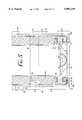
- FIG. 1is a schematic representation of the heart and various vasculature showing an automatic purse string suture applicator of the present invention operatively positioned to apply a purse string suture to cardiac tissue.
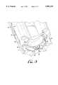
- FIG. 2is a side elevational side view of a tubular structure of an automatic purse string suture applicator of the present invention.
- FIG. 3is a longitudinal sectional view of the tubular structure taken along line 3--3 of FIG. 2.
- FIG. 4is an exploded view of the tubular structure illustrated in FIG. 2.
- FIG. 5is an enlarged illustration of the distal end of the tubular structure shown in FIG. 3.
- FIG. 6is a perspective view of an enlarged illustration of the distal end of the tubular structure shown in FIG. 5 having a surgical needle with an attached suture thread operatively positioned within its needle passage and showing one embodiment of a needle removal mechanism in a closed position.
- FIG. 7shows a perspective view of the tubular structure and an attached needle driving knob, both having corresponding markings for proper alignment to ensure timely activation of the needle removal mechanism.
- FIGS. 8A and 8Billustrates the tubular structure having an alternate embodiment of a means for removing a needle from the needle passage.
- FIG. 9is a schematic illustration of a tubular structure operatively positioned to apply a purse string suture to a vessel lumen with its wall compressed against the distal edge of the tubular structure in preferably sinusoidal configuration and a needle with an attached suture thread partially advanced through its annular route.
- FIG. 10shows a cut-away portion of the tissue wall of FIG. 9 having a purse string suture provided in the wall.
- FIG. 11Ais a schematic illustration of a needle being advanced through a segment of a vessel wall by needle advancing disks of an automatic purse string suture applicator of the present invention, wherein the needle extends through less the than the entire thickness of the tissue wall.
- FIG. 11Bis a schematic illustration of the tissue wall segment of FIG. 11A having a suture thread therein which passes through less than the entire thickness of the tissue wall.
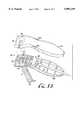
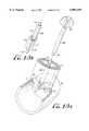
- FIG. 12is a schematic illustration of a purse string suture applicator of the present invention having a suction-based means for engaging the tissue against the distal end the tubular structure.
- FIG. 13is an exploded view of a purse string suture applicator employing an alternate suction-based means for engaging tissue.
- FIG. 14is a schematic illustration of a purse string suture applicator of the present invention employing a gripper-type means for capturing tissue within the tissue bays of the tubular structure.
- FIG. 14Ashows the components of the gripper means of FIG. 14.
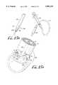
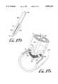
- FIG. 15Ais schematic representation of another embodiment which employs an expandable balloon mechanism in an expanded or inflated condition for compressing the wall of the vessel lumen to be sutured against the distal edge of the tubular structure.
- FIG. 15Bshows the distal end of the tissue compressing device of FIG. 15A when in a closed position.
- the tip of the distal endis configured to have a trocar-like pointed tip for puncturing tissue.
- FIG. 16Ais schematic representation of another embodiment of the tissue conforming means of the present invention in an active or open position.
- This embodimentemploys an umbrella-like deployment mechanism having a plurality of support members.
- FIG. 16Bshows the distal end of the tissue compressing device of FIG. 16A when in a closed position.
- the tip of the distal endis also configured to have a trocar-like pointed tip for puncturing tissue.
- FIG. 17Ais yet another embodiment of the tissue conforming means of the present invention utilizing an expandable braided sheath, shown here in an open state.
- FIG. 17Bshows the distal end of the device of FIG. 17A in a closed position.
- FIG. 18shows a cross-section of an embodiment of the present invention employing a blade mechanism to incise the tissue wall for placement of a cannula.
- FIG. 18Ashows an enlarged view of the blade mechanism of FIG. 18A.
- FIG. 19is an embodiment of a dual purse string suture applier for placing two concentric rows of purse string sutures in a vessel wall.
- FIG. 1a schematic representation is provided of a heart 2 with various arterial and venous vasculature, and shows a elongated structure or body or structure 10 of the purse string suture applicator of the present invention operatively positioned for automatically applying a purse string suture to a vessel lumen or hollow tissue structure 3 which, in FIG. 1, is the aorta.
- the purse string suture applicatoris "automatic" in that it eliminates the manual application of sutures to the tissue, and quickly and accurately applies a suture to tissue with minimal steps and in less time than manual suturing.
- structure 10is designed to have dimensions and a shape to be easily inserted through a surgical opening in the chest, including minimally invasive openings or delivered to the target site via a trocar sheath.
- elongated structure 10is a tubular housing but may have other configurations, such as a rectangular shape, and may also be a rod having a distal end having a selected configuration for passing a needle through a defined passage.
- the distal edge 19 of structure 10has a contoured surface for contacting the tissue to be sutured.
- the contoured surfaceis castellated or substantially sinusoidal, but may be configured of spaced-apart triangular, rectangular, circular, hexagonal, or other shaped protrusions.
- a needle passage(not shown) is defined within the distal end for holding an needle (also not shown) having a suture thread 37 attached.
- a needle driving meanssuch as a knob 39 at the proximal end of tubular structure 10, is employed to advance the needle through the passage.
- the present inventionalso provides various means, which are not shown in FIG. 1, for conforming the targeted tissue to the contoured distal edge 19.
- the means for conforming the tissuemay include suction or grasping means integral with tubular structure 10 and are adapted to function completely external to the vessel lumen.
- the conforming meansmay include a deployable or expandable mechanism, such as a balloon, braided sheath, or deployable support members which are inserted into the tissue structure or lumen in a deflated, retracted, or closed position and then inflated, expanded, or deployed to compress the tissue wall against the distal edge of the elongated tubular structure 10.
- the application of a suture using the present inventioninvolves contacting the contoured distal edge 19 of an elongated structure or body or housing 10 at the target tissue site and then conforming the adjacent tissue to the contoured distal edge 19.
- Various means for conforming the tissue to the distal edge 19are contemplated and are described in detail below. While the tissue is compressed against distal edge 19, the annular surgical needle (not shown) and attached suture thread 37, which are held within the needle passage, which is preferably annular, are caused to pass through the conformed tissue.
- annular surgical needleas used herein means a ring or circle or portion thereof. Advancing the needle is accomplished in the embodiment shown by manually rotating knob 30.
- the needle and attached end of the suture 37are removed from the tubular structure 10, either by passive or active disengagement means, the various embodiments of which are also described in detail below.
- the tubular structure 10is then removed from the surgical site.
- the needleis cut from the suture thread 37 and a choker 8 may then be applied over the trailing ends of the suture thread. Forceps or a hemostat 9 may be used to hold the choker 8 in place.
- a cannula entry siteis formed after placement of a purse string suture by cutting or puncturing the area of tissue defined by the purse string suture.
- a purse string suture 6has been applied in the wall of the right atrium 5 in FIG. 1.
- the cannula entry siteis necessarily formed prior to providing a purse string suture.
- a cannula, such as the venous cannula 7,is placed within the respective tissue structure or lumen, and the purse suture 6 is tightened by means of choker 8.
- FIGS. 2-4there is shown one embodiment of a tubular structure 10 which houses some of the components of the purse string suture applicator.
- Tubular structure 10includes an outer tubular member 12 and an inner tubular member 14 both of which are preferably made of plastic.
- Outer tubular member 12is preferably long enough to extend through a surgical opening, such as in the chest, and reach the surface of the vessel, organ, or other tissue structure or lumen to which a purse string suture is to be applied. Accordingly, outer tubular member 12 preferably has a length from about 8 to about 15 cm (3 to 6 inches).
- the center-to-center diameter of the annular needle passage (not shown) of outer tubular member 12defines the diameter of the purse string suture to be applied.
- the center-to-center diameter of the annular needle passage outer tubular member 12be about 3 mm greater than that of the arterial cannula.
- the center-to-center diameter of the annular needle passage defined in outer tubular memberis approximately 10 mm and 13 mm for the inner and outer purse string sutures, respectively.
- outer tubular member 12As a typical size for a venous cannula is about 32 French, the diameter of the associated purse string suture for a venous cannula application is approximately 13.5 mm, or about that of the outer arterial purse string suture. However, it should be understood that the particular length and diameter dimensions of outer tubular member 12 will vary depending on the surgical application (arterial, venous, or cardioplegia cannulation) and individual patient anatomy.
- the distal edge 19 of outer tubular member 12is configured so as to have distally-extending, spaced-apart or staggered extended sections or protrusions 20.
- extended sections 20are evenly spaced-apart and have uniform dimensions.
- sections or protrusions 20contact the tissue to be sutured upon insertion of outer tubular member 12 through a surgical opening, for example, in the chest.
- the configuration of distal edge 19is designed such that when the tissue between protrusions 20 are caused to engage the portions of distal edge 19 between protrusions 20, referred to as tissue "bays" 22, the tissue is conformed to a wavy or sinusoidal configuration. For example, in the embodiment shown in FIGS.
- distal edge 19forms a substantially castellated configuration or pattern having extended sections 20 and spaces or bays 22.
- distal edge 19may have sections 20 which are rounded to form a sinusoidal configuration, as shown in FIGS. 1 and 8, such that sections 20 may be defined as "crests” or “peaks,” and bays 22 there between may be defined as “troughs” or “valleys.”
- outer tubular member 12has four, five or six extending sections or protrusions 20. More particularly, in one embodiment, outer tubular member 12 preferably has four or five protrusions 20 for applying a purse string suture (both inner and outer sutures) to a major artery such as the aorta. In an embodiment for applying a purse string suture to a major vein, such as the vena cavae, or the atrial wall, outer tubular member 12 preferably has five or six protrusions 20. However, it should be understood that, depending on the surgical application, outer tubular member 12 may have more or less protrusions 20, such as two, three, seven, eight, nine, ten, eleven or more.
- Inner tubular member 14may be a single housing structure, or have multiple tubular sections to incorporate certain limitations in the advancement or rotation of inner tubular member 14 with respect to outer tubular member 12.
- inner tubular member 14is shown to have two sections, an upper or proximal section 14a and a lower or distal section 14b.
- Inner tubular member 14, and each of sections 14a and 14bare dimensioned to be rotationally and longitudinally engagable within outer tubular member 12.
- the proximal end 17 of lower section 14b and the distal end 15 of upper section 14aare configured with a mating configuration which prevents rotational movement of sections 14a and 14b relative to each other.
- distal end 15 of upper section 14ahas an extending inner wall having opposing openings 15a and 15b.
- Proximal end 17 of lower section 14bhas an extending inner wall having opposing flanges 17a and 17b which matingly engage with opposing openings 15a and 15b, respectively.
- a retainer or stopper mechanism 16is provided in the wall of outer tubular member 12 to retain or prevent proximal section 14a from extending or traveling axially downward or distally within outer tubular member 12 beyond a selected point, and likewise, maintains distal section 14b from traveling upwards or proximally.
- Retainer 16includes two oppositely positioned retainer plugs 16a and 16b which, when inserted into respective holes 18a and 18b in the wall of outer tubular member 12, are flush with the outer wall and extend internally to reside in an annular groove at the distal end 15 of upper section 14a.
- the distal end 17 of upper section 14ais configured to fit within lower section 14b when both sections are operatively positioned within outer tubular member 12.
- a needle advancing mechanismwhich, in part, consists of a plurality of needle advancing disks or wheels 24 integrally mounted to the inside of outer tubular member 12.
- disks 24are rotationally mounted on a corresponding hub 26a within an annular rack or ring 26.
- Disks 24are preferably made of a deformable or compressible material, such as rubber, for facilitating frictional engagement of a needle.
- the diameter of disks 24will depend on the size of the purse string suture applicator and the number of disks employed (i.e., more disks, the smaller their diameters), and is about 1/4 the diameter of the annular needle passage.
- Each disk 24is held in place by means of a clip or pin 27 through hubs 26a.
- Rack 26sits on ledges or lips 32 inwardly extending from respective protrusions or peak sections 20.
- the upper surface 32a of each ledge 32has an arcuate groove or channel 34 therein which collectively define an annular passage extending 360° for holding an annular surgical needle 36 having suture thread 37 attached thereto.
- Rack 26is positioned such that each disk 24 rests upon a ledge 32. More particularly, the circumferential surface of each disk 24 is tangentially aligned with the annular needle passage such that, when an annular surgical needle 36 is operatively positioned within the annular passage, disks 24 frictionally engage needle 36.
- disks 24Accordingly, the rotation of disks 24 cause needle 36 to be advanced through the annular passage.
- disks 24there is a one-for-one correspondence of disks 24 to protrusions or peak sections 20.
- the embodiment illustratedhas four disks 24 and corresponding protrusions 20 (not all are shown), any number of disk-protrusion pairs may be employed by the present invention as dictated by the particular surgical application.
- Needle 36has a sharp point at one end and a suturing thread 37 attached to the other end. It is preferably made of stainless steel, however, other surgical grade materials are suitable. Needle 36 preferably has the same radius of curvature as the annular needle passage 34.
- the minimum and maximum arc lengths of needle 36are dependent upon the number of protrusions 20 and, thus, the number of disks 24 employed within the purse string suture applicator of the present invention.
- needle 36has a minimum arc length such that it is in contact with at least one disk 24 at any position when operatively engaged within the annular needle passage.
- the maximum arc length of needle 36is such that it can be easily removed from the annular needle passage. In one embodiment, the maximum arc length of needle 36 is such that it can be radially disengaged from the annular passage by means of a needle removal means, discussed in detail below with respect to FIGS. 6 and 7.
- Retainer mechanism 16limits the downward force imparted by a surgeon or other user to top section 14a from transferring to lower section 14b. As such, the rotational force on disks 24 is optimally fixed (at about 0.5 to 2.5 lbs/sq 2 ) so that disks 24 are able to be rotated in a controlled manner and advance needle 36 freely through the annular passage.
- needle 36may be advanced in a continuous manner through one or more (360°) rotations, or may be incrementally advanced as desired. In most surgical applications, however, it is preferable to provide only a single series or rotation of stitches between trailing thread ends of a purse string suture.
- the purse string suture applicator of the present inventionis equipped with a needle removal mechanism which is designed to remove or eject needle 36 from the annular needle passage upon one complete rotation of the needle.
- the needle removal mechanismincludes at least one extending section 38 which can be radially disengaged or projected outward from outer tubular member 12.
- extending section 38is hinged at the outer wall of outer tubular member 12 by means of a wire spring mechanism 39 which is held in place by a pivot clip 43. Spring mechanism causes section 38 to be inwardly biased and in a normally closed position.
- the needle removal mechanismfurther includes an annular recess or groove 40 circumferentially disposed about the distal end 41 of tubular lower section 14b, and a ramped notch 42 protruding from the inner wall of radially disengageable section 38 and which is received within annular recess 40.
- Annular recess 40encircles slightly less than 360° of distal end 41 and thereby defines a contact point 44 whereby the radially disengageable section 38 is projected radially outward from outer tubular section 12 when contact point 44 is caused to engage notch 42.
- section 38is caused to disengage with needle 36 disposed within its respective arcuate channel 34 after needle 36 has substantially traveled one rotation through the annual needle passage.
- hatch marks 45a and 45bare preferably provided on outer tubular housing 12 for rotational alignment with corresponding hatch mark 46 on inner tubular housing 14 and/or knob 30. Alignment of hatch mark 45a with hatch mark 46, properly positions inner tubular housing 14 prior to rotation of knob 30 and, in particular, positions annular recess 40 about ramped notch 42 such that notch 42 is allowed to travel the entire arc length of recess 40 before notch 42 engages contact point 44.
- Alignment of hatch mark 45b with hatch mark 46indicates that needle 36 has been removed or disengaged from the annular needle passage by the radially disengagement of section 38 as shown in FIG. 7.
- the hatch marksare particularly helpful when operating the purse string suture applicator through minimally invasive surgical openings which provide limited visual access. Such a marking protocol further ensures that purse string suture applicator is not removed from a target site while a needle is embedded within the tissue.
- the annular needle passage(identified in phantom) defined within the distal end of outer tubular member 12 is slightly helical or spiraled such that a needle 36 operatively positioned therein advances in a slightly downward helix.
- needle 36commences its advancement through the passage at a level or position (see the cut-away portion in outer tubular member 12 as illustrated in FIG. 8A) which is more elevated than or proximal to the position or level (see the cut-away portion in outer tubular member 12 as illustrated in FIG. 8B) at which needle 36 is in upon completion of one revolution through the annular passage.
- the distal end of outer tubular member 12has two consecutive extending sections 20a and 20b and the common tissue bay 22a therebetween which, collectively, are less contoured than the remainder of the distal end.
- the plurality of disks 24, which, in the embodiment of FIGS. 8A and B, number six to correspond with the six extending sections 20 of outer tubular member 12, and unlike the above embodiments,are not centrally aligned with the extending sections 20 but are proximately positioned to respective sloping portions 50 between extending sections 20 and tissue bays 22.
- the disk 24awhich is the last disk engaged by needle 36 before completing a revolution and which is approximately aligned with section 20a, is slightly, vertically offset or lower than the other disks 24.
- Needle 36is caused to exit its helical path and engage from the tubular structure at a defined exit point 51.
- needle 36is advanced through the wall of the vessel lumen 60 and then directed downward and out of outer tubular member 12. The needle can then be grasped and the tubular structure 10 is freely removed, unencumbered by the attached suture thread 37 and trailing end thereof.
- needle 36is preferably preloaded in a selected position within the annular needle passage to further ensure the complete and proper placement of all stitches, and ensure timely disengagement, if necessary, of a needle from the tubular structure.
- the maximum arc length of needle 36is such that it can be removed, driven out, or radially disengaged from the annular passage by means of a needle removal mechanism or means such as those described above.
- the arc length of the needle usedis preferably not greater than the width of section 38 so as to be free from catching onto or tearing through tissue held within the tissue bays 22 on either side of section 38 when being removed from an operative position within the annular passage. Similar limitations are true for suture applicators employing other needle removal means.
- the arc lengthis further dictated by the number of extending sections 20 and disks 24 that are employed.
- a purse string suture applicator having four disks 24 and extending sections 20should employ a needle having a minimum arc length of no less than about 1/4 the are length of the annular needle passage.
- an applicator having six disks 24 and corresponding sections 20should employ a needle having a maximum arc length of no more than about 1/6 that of the annular needle passage.
- the exact shape or form of the compressed tissue 60will vary, but preferably takes on a substantially sinusoidal configuration for any configuration of distal edge 19 as shown in FIG. 9.
- a schematic representationis provided of a silhouette of an outer tubular member 12 operatively engaging the wall of a cut-away of a vessel lumen 60.
- the distal edge 19 of outer tubular member 12has a substantially sinusoidal configuration having, for example, six protrusions 20 and corresponding tissue bay sections 22 such that the tissue conformed thereto takes on a similar, substantially sinusoidal configuration having six peaks 61 and valleys 62.
- a needle 36 with an attached suture thread 37is shown having been advanced through the portion of tissue wall engaged within tissue bays 22.
- the resulting purse string sutureis shown in FIG. 10 where thread 37 has been passed four times through the wall of vessel lumen 60 (only a cut-away portion is shown) with two trailing ends 37a and 37b remaining after the needle 36 has been cut off.
- FIG. 11Aschematically shows two needle advancing disks 24 driving a needle through respective arcuate channels 34 of sections 20, and penetrating tissue wall 60 which has been conformed to the sinusoidal distal edge of outer tubular member 12.
- the vertical distance 53 from the distal edge at the midpoint of an extended section 20 to the distal side of needle 36is selected such that needle 36 does not penetrate through the entire thickness 55 of tissue wall when advanced therethrough.
- the value of distance 53is one third (1/3) to two thirds (2/3) less than tissue wall thickness so as not to completely penetrate the wall thickness 55 and to minimize the risk that the applied suture will tear through the tissue wall when pulled or tightened.
- the thickness of the tissue wallranges from 1 to 3 mm for the aorta, 1 to 2 mm for the vena cavae, and 1-3 mm for the atrium. Accordingly, distance 53 will range from less than 1 mm to about 2 mm depending on the vessel being sutured.
- the vertical distance 54 from the distal edge at the midpoint of an extended section 20 to the midpoint of a tissue bay 22is preferably between about 1.5 to 3.5 mm.
- the purse string suture applicator of the present inventionfurther includes means for releaseably engaging or compressing the tissue to be sutured into the several tissue bays or valleys 22 of the outer tubular member 12.
- FIGS. 12-16illustrate various embodiments of such a tissue engaging or compressing means and methods of engaging or compressing tissue against the distal edge of tubular structure 10.
- a schematic illustrationis provided of the distal section of tubular structure 10 having outer 12 and inner tubular members 14 operatively engaged against the outer wall of a segment of vessel lumen 60.
- outer tubular memberhas an optimally contoured distal edge for engaging and conforming the tissue wall
- inner tubular member 14generally functions to drive or advance an arcuate needle (not shown) through an annular passage internal to and within the distal end of tubular structure 10. Additionally, for each embodiment illustrated, a proximal portion of either tubular structure 10 or an actuator mechanism for the tissue engaging means is shown.
- a preferred embodimentemploying suction or negative pressure to draw up or engage tissue into tissue bays 22.
- Integral to tubular structure 10,and housed within outer tubular member 12are a plurality of pneumatic pathways 70, and preferably there is a one-for-one correspondence of pathways to tissue bays 22.
- a pathway 70extends from a distal port (not shown) flush with the distal edge 19 at each tissue bay 22 to a proximal port 72 at the proximal edge 71 of outer tubular member 12.
- the means for applying a negative pressure through pneumatic pathways 70includes an annular attachment head 74 configured to sealingly engage with the proximal edge 71 of outer tubular member 12.
- An annular channel 75is housed within annular attachment head 74 and is pneumatically connected with each pneumatic pathway 70.
- a port 76pneumatically connects channel 75 to a vacuum or negative pressure source (not shown), which may be any model suitable for use in surgical applications.
- a vacuum or negative pressure source(not shown)
- the wall of the vessel lumen 60is drawn against the distal edge between the protrusions 20, conforming the wall to a substantially sinusoidal configuration.
- the needle(not shown) can then be advanced through the internal annular channel (not shown) and the tissue segments held within tissue bays 22 by rotating inner tubular member 14 as discussed above with respect to FIGS. 1-7. Once the needle has completed a revolution, the vacuum source can be turned off to release the tissue from the tissue bays 22.
- FIG. 13shows an alternate embodiment of a suction-based means for engaging tissue against distal edge 19.
- a suction device 80is provided wherein the top portion 81a of a preferably plastic-molded, handle-shaped housing 81 is shown exploded away from the bottom portion 81b of the housing to display the internal structure of the device 80.
- Device 80has an annular attachment head 82 which is configured to easily and quickly "snap onto” and become sealingly engaged to the proximal end of outer tubular member 12, such as that shown in FIG. 12, wherein proximal ports 72 are automatically aligned and in pneumatic connection with corresponding vacuum tubes 83.
- Vacuum tubes 83which are made of stainless steel or can be flexible plastic tubing, extend rearwardly within housing 81 where they are collectively coupled to a single pneumatic connection tube 84 which in turn extends out of housing 81 to a vacuum source (not shown).
- a spool-shaped vacuum actuator or switch 85is provided on top of and is rotationally engageable with vacuum tubes 83 to control the application of negative pressure through vacuum tubes 83.
- Actuator 85includes dual dials 86 sized to extend through openings 87 in upper housing 81a and corresponding openings (not shown) in lower housing 81b when the two housing sections are sealed together, forming a handle.
- Handle 81is intended to be ergonomically held within one hand, and dials 86 are positioned to be rotationally adjustable by the thumb of the hand in which the device 80 is held.
- Vacuum tubes 83are in a normally open state, providing suction through pneumatic pathways 70 and causing tissue to be engaged within tissue bays 22 (see FIG. 12).
- actuator 85When rotated forward towards annular attachment head 82, actuator 85 is caused to compress vacuum tubes 83, closing off the negative pressure to pneumatic pathways 70 and releasing tissue from tissue bays 22.
- the forward end of housing 81comprises a funnel-shaped portion 88 having an opening 89 extending through annular attachment head 82.
- a needle driving actuatorsuch as knob 30 in FIGS. 1-4 and 7, may be positioned within opening 89 and operatively coupled to the proximal end 29 (see FIG. 3) of inner tubular member 14 for driving a needle during the application of suction.
- FIG. 14another embodiment of the present invention is provided which employs a plurality of grasping members 90 integrally adapted to outer tubular member 12 for grasping tissue 60.
- Each grasping member 90includes a pair of coacting jaws 97 which define a tissue bay 22 and are operatively configured to grasp tissue.
- Coacting jaws 97preferably have teeth at their distal ends to facilitate the a traumatic grasping of tissue.
- Coacting jaws 97articulate about a hub 98 having a ribs 98a which ride in an opposing groove 97a on the inside surface of each coacting jaw 97.
- grasping member 90a(left-hand side as viewed) is shown to be in a normally open position.
- grasping member 90b(right-hand side as viewed) is shown in a closed or grasping position; however, it should be noted that all grasping members 90 work synchronously such that all are simultaneously open or closed.
- Jaws 97are mounted to plate 93 by means of retainer posts 93a.
- a rod 91which is slideably engaged within and extends longitudinally through a respective lumen of the wall of outer tubular member 12, extends distally through a bore in retainer plate 93b and is fixed to hub 98.
- rod 91is coupled to an actuator mechanism 92 which acts to pull up on rod 91 to close jaws 97 (as seen by grasping member 90b).
- Actuator mechanism 92comprises two stacked annular sections, a lower section 100 which is rotatably mounted to the proximal end of outer tubular member 12, and an upper section 101, which is moveable only in a vertical direction along the axis of the tubular structure.
- Each of sections 100 and 101have multiple cam protrusions on their opposing surfaces.
- Each protrusionhas a vertical side 100a, 101a and a ramped side 100b, 101b to produce a rectilinear motion upon rotating lower section 100.
- the proximal end of each rod 91extends through and is movable within an arcuate slot 102 within lower section 100, and is rigidly fixed to upper section 101.
- actuator mechanism 92shows sections 100 and 101 "seated” within each other, maintaining respective rod 91a in a lower position, and thus, jaws 97 of grasping member 90a in an open position.
- Rotating lower section 100 in the clockwise direction from this seated positioncauses sections 100 and 101 to become unseated, as shown in the right-hand portion of actuator mechanism 92, pulling up on respective rod 91b.
- a spring coil 94that encircles rod 91 and is positioned between plate 93b and the "arch" 104 of outer tubular member 12, acts to bias grasping member 90b vertically downward.
- a needle driving actuatorsuch as knob 30 in FIGS. 1-4 and 7, may be positioned within tubular structure 10 to engage with inner tubular member 14 (see FIG. 3) for driving a needle during actuation of grasper members 90.
- FIGS. 12-14After the application of the purse string suture is complete, and the purse string suture applicator has been removed from the surgical area, it is necessary to create an incision in the vessel lumen 60 for insertion of a cannula. This is commonly done by means of an independent surgical instrument, typically a scalpel or trocar. However, it is contemplated, as shown in FIG. 18, that an integral cutting element, such as blade 150, be housed within tubular structure 10. As shown, blade 150 is hinged to the distal end of a rod 158 which extends through inner tubular member 14. Blade 150 is preferably made of stainless steel and has a length that extends between the inner and outer diameters of inner tubular member 14.
- the hinged end 152 of blade 150has a notch 153 which firmly engages a recessed spring plate 155 embedded in the wall of inner tubular member 14.
- Hinged end 152resides within a first slotted recess 156 in inner tubular member 14, causing the length of blade 150 to be normally positioned substantially perpendicular to the longitudinal axis of tubular structure 10.
- the opposite end of blade 150extends into a second slotted recess 157 within inner tubular member 14, directly opposite of first slotted recess 156.
- Recess 156 and 157are each located between adjacent disks 24 so that motion of blade 150 is not impeded by disks 24.
- blade 150is positioned such that the plane in which it moves bisects the cross-sectional area of the lumen defined by inner tubular member 14.
- a purse string suture(not shown) has been provided, a cannula 160 can be inserted into inner tubular member 14 to engage blade 150, causing it to overcome the bias of spring plate 155 and rotating it radially about hinged end 152.
- blade 150comes to rest at a position parallel to the longitudinal axis of tubular structure 10.
- Rod 158extends proximally through the proximal end of inner tubular member 14 and is controllable by a surgeon to axially rotate blade 150 90° so that blade 150 is substantially flush with the inner wall of inner tubular member 14.
- FIGS. 15-17Other embodiments of the tissue conforming means of the present invention are illustrated in FIGS. 15-17.
- a deployable or expandable mechanismwhich is inserted into the tissue structure or lumen and deployed or expanded to compress the tissue wall against the contoured distal edge of tubular structure 10.
- the particular deployable or expandable mechanismmay comprise a balloon (FIG. 15), an expandable braided material (FIG. 16), an umbrella-like device (FIG. 17), or combinations of thereof which are operable between open (expanded or deployed) and closed (constricted or deflated) positions.
- An expansion or deployment actuator mechanismis proximally provided to be easily controlled by a surgeon.
- a rigid elongated tubeoperatively extends between the actuator mechanism and the deployable/expandable member which, in a closed position, may be configured so as to form a pointed cutting or puncturing tip to penetrate the tissue around which the purse string suture is to be placed and through which the deployable/expandable mechanism is delivered.
- This puncture sitereadily provides an opening for the entry of a cannula within the vessel lumen 60.
- FIG. 15shows a balloon-type mechanism for conforming tissue which has been inserted axially through outer 12 and inner 14 tubular members.
- the mechanismincludes a rigid slender introducer tube 105 which is preferably made of a polymeric material.
- the distal tip 106 of introducer 105consists of a plurality of deployable structural support members 107 which, when in a closed position as shown in FIG. 15A, form a trocar-like point which is capable of puncturing tissue. In the closed position, tip 106 retains an expand able balloon 108 which is in fluid communication with an inflation/deflation mechanism 112 via a flexible, catheter-like tubing 114.
- the inflation/deflation mechanism 112is preferably a syringe for delivering a fluid, such as saline, to expand or inflate balloon 108 as well as to deflate balloon 108.
- Balloon 108has an expanded volume which can be a traumatically accommodated by the vessel or lumen in which it is inserted.
- Balloon 108is preferably made of latex or another suitable elastomeric material and is preformed in a configuration which readily conforms to the configuration of the distal edge 19 of outer tubular member 12.
- the top surface of balloon 108is preformed in a substantially sinusoidal shape to match the preferably substantially sinusoidal configuration of distal edge 19.
- Structural support members 107have fingers 107a which, when in an open or deployed position as shown in FIG. 15, spread apart from each other.
- Structural support members 107are preferably made of flexible stainless steel so as to be rigid enough to penetrate tissue when closed but flexible enough to accommodate expansion of balloon 108.
- support members 107help to further maintain balloon 108 in its preformed configuration, and are intended to be aligned under protrusions 20 of outer tubular member 12 when operatively positioned within the targeted tissue structure 60.
- a very thin, flexible metallic ringmay also be provided on the preformed surface of balloon 108. The ring would follow the sinusoidal path to guard against the possibility of a needle puncturing balloon 108 in the case where the tissue wall 60 is exceptionally thin.
- a needle driving actuatorsuch as knob 30 in FIGS. 1-4 and 7 but having an annular configuration so as to accommodate the actuator mechanism 112, catheter 114 and tube 105, can be used to rotationally advance a needle through the tissue within tissue bays 22.
- the annular needle passageis configured such that a needle is driven through less than the entire thickness of the tissue wall, obviating the risk of the needle puncturing balloon 108.
- the expansion fluidis withdrawn by means of syringe 112, and tube 105 is pulled up through tubular structure 10.
- FIGS. 16 and 16Ashow another embodiment of the tissue compressing means of the present invention employing an umbrella-like deployment mechanism 110 having a plurality of support members 111.
- Support members 111have substantially rectangular shapes with tapered ends to provide a stream-line shape for puncturing tissue 60 but may, however, be cylindrical or have any other suitable shape.
- Support members 111are attached to introducer tube 105 by individual hinge mechanisms 119 which allow outward deployment of members 111. Their lengths are approximately that of the radius of outer tubular member 12, thus, allowing them to be deployed at right angles to tube 105 within vessel lumen 60 without contacting the inner tissue wall opposite the puncture site.
- a rigid elongated introducer tube 105extends between deployment mechanism 110 and an actuator mechanism or rotatable knob 115. Extending through tube 105 is a rod 116 which terminates distally in a somewhat bulbous member 121 having pointed tip 117 which is suitable for puncturing vessel lumen 60 to provide an entry site for deployment mechanism 110.
- Rod 116is threaded at its proximal end to a threaded receptacle (not shown) within knob 115, such that when knob 115 is rotated in a counter-clockwise direction, rod 115 is caused to travel upward.
- tip 117punctures vessel lumen 60 introducing deployment mechanism 110 within vessel lumen 60.
- Actuation of rod 116causes member 121 to move upwards and engage the inner surfaces of support members 111, forcing them to deploy radially outwards.
- the final position of support members 111is locked by the geometry of tip 117.
- a needle driving actuatorsuch as knob 30 in FIGS. 1-4 and 7 but having an annular configuration so as to coaxially accommodate the actuator mechanism 115 and tube 105, can be used to rotationally advance a needle through the tissue within tissue bays 22. After a complete rotation of the needle through the tissue, the support members 111 are retracted radially inwards by means of rotating knob 115 clockwise, and tube 105 is pulled up through and out of tubular structure 10.
- the deployment mechanism 130consists of an expandable cylindrical sheath 131, such as a polymeric braid (e.g., polyethylene). Also included are an elongated rigid introducer tube 105, a rod 116, pointed tip 117, and an actuator mechanism (not shown), such as the rotatable knob 115 described with respect to FIG. 16A, which are structurally and functionally similarly to the embodiment of FIGS. 16A and 16B.
- the distal end of sheath 131is attached to pointed tip 117 and the proximal end is attached to the distal end of tube 105. In a closed position, as shown in FIG.
- braided sheath 131is compressed and maintains a profile which facilitates the entry into vessel lumen 60.
- a plurality of spaced-apart, flexible braces or support members 132are provided which are attached to and extend along the length of braided sheath 131, creating spaced-apart braided segments 133.
- sheath 131 and braces 132are such that the entire length of deployment mechanism 130 can be inserted into lumen 60 without tip 117 contacting the inner tissue wall opposite the puncture site. Similarly, the length is such that the distance which sheath 131 is caused to radially expand is not substantially greater than the radius of outer tubular member 12.
- a needle driving actuatorsuch as knob 30 in FIGS. 1-4 and 7 but having an annular configuration so as to coaxially accommodate the actuator mechanism 115 and tube 105, can be used to rotationally advance a needle through the tissue within tissue bays 22. After a complete rotation of the needle through the tissue, tip 117 is caused to travel downward, stretching sheath 131 and braces 132 into their closed positions, and tube 105 is pulled up through and out of tubular structure 10.
- a tubular structure 10includes an outer tubular member 200 having a plurality of distally hinged H-shaped segments 202 (four are shown but more may be employed) having two concentric annular needle passages, outer needle passage 204 and inner needle passage 206.
- an inner tubular member 220engages two concentric sets of disks, outer set 172 and inner set 170 which act to rotationally engage annular needles 205 and 207, respectively.
- Inner tubular member 220 and disks 170 and 172function in a fashion similar to previously discussed embodiments.
- Segments 202define an outer and inner set of tissue bays 210 and 212, respectively, which are shaped to receive an outer and inner set of fingers 222 and 224, respectively, of tissue conforming means 225. Based on this configuration, needles 205 and 207 are preferably preloaded so as to be offset approximately 45° from each other, as shown in FIG. 19.
- tissue conforming means 225is comprised of a preformed latex balloon which, in a deflated condition, is housed within the distal end of rigid elongated introducer tube 105.
- tip 117is used to puncture a vessel lumen (not shown) and deliver the distal end within the lumen.
- fluidis injected into balloon 225 to expand preformed fingers 222, 224 radially outward and upward from slots 226 circumferentially disposed about the distal end of tube 105. Fingers 222, 224 are maintained in an upward position by a respective webbed sections 227.
- fingers 222, 224are drawn up to compress the wall of the vessel lumen into respective tissue bays 210 and 212. Needles 205 and 207 can then be advanced through the tissue within the tissue bays. After the dual purse string sutures are placed, balloon 225 is deflated and fingers 222, 224 are withdrawn into introducer tube 105. Tubular structure 10 is then slightly lifted to allow hinged segments 202 to be radially disengaged by means of a proximally-controlled rod (not shown) housed within outer tubular member 200. Needles 205 and 207 can then be grasped, and pulled through their last stitch or "bite,” if necessary.
- a purse string suture applicatorfor automatically applying a purse string suture to tissue in vivo through any sternal or thoracic surgical opening including, but not limited to, a sternotomy, thoracotomy, mini-sternotomy, mini-thoracotomy, and transthoracically through a trocar sheath.
- a purse string sutureto one wall of a vessel lumen, often required in cardiac surgery for the purpose of cannulating the heart and major vessels of the heart, has been described.
- a preferred aspect and method of the present inventionis to provide a purse string suture which extends through less then the entire thickness of the tissue wall.
- the present inventiongreatly reduces the time necessary to place a purse string suture.
- purse string suture structure and the associated needle passage thereinhave been preferentially described to have tubular and annular configurations, respectively, it will be understood by those skilled in the art that other configurations which are suitable for providing a purse string suture are acceptable for the present invention.
Landscapes
- Health & Medical Sciences (AREA)
- Life Sciences & Earth Sciences (AREA)
- Surgery (AREA)
- Heart & Thoracic Surgery (AREA)
- Engineering & Computer Science (AREA)
- Biomedical Technology (AREA)
- Nuclear Medicine, Radiotherapy & Molecular Imaging (AREA)
- Medical Informatics (AREA)
- Molecular Biology (AREA)
- Animal Behavior & Ethology (AREA)
- General Health & Medical Sciences (AREA)
- Public Health (AREA)
- Veterinary Medicine (AREA)
- Surgical Instruments (AREA)
Abstract
Description
Claims (47)
Priority Applications (1)
| Application Number | Priority Date | Filing Date | Title |
|---|---|---|---|
| US08/850,321US5891159A (en) | 1997-05-02 | 1997-05-02 | Automatic purse string suture device |
Applications Claiming Priority (1)
| Application Number | Priority Date | Filing Date | Title |
|---|---|---|---|
| US08/850,321US5891159A (en) | 1997-05-02 | 1997-05-02 | Automatic purse string suture device |
Publications (1)
| Publication Number | Publication Date |
|---|---|
| US5891159Atrue US5891159A (en) | 1999-04-06 |
Family
ID=25307819
Family Applications (1)
| Application Number | Title | Priority Date | Filing Date |
|---|---|---|---|
| US08/850,321Expired - Fee RelatedUS5891159A (en) | 1997-05-02 | 1997-05-02 | Automatic purse string suture device |
Country Status (1)
| Country | Link |
|---|---|
| US (1) | US5891159A (en) |
Cited By (82)
| Publication number | Priority date | Publication date | Assignee | Title |
|---|---|---|---|---|
| DE19927422C1 (en)* | 1999-06-16 | 2001-02-15 | Jostra Ag | Device for cannulating vessels and for stopping and / or limiting bleeding |
| DE10147632A1 (en)* | 2001-06-08 | 2003-01-09 | Fraunhofer Ges Forschung | Device used in surgery for connecting hollow organs and/or closing wall defects of hollow organs comprises a base holder having a recess on a first surface and a guide path for a spiral needle |
| US20030078592A1 (en)* | 2001-10-23 | 2003-04-24 | Heilman Marlin Stephen | Method and apparatus for attaching a conduit to the heart or a blood vessel |
| US6569182B1 (en)* | 1998-09-09 | 2003-05-27 | Embol-X, Inc. | Introducer/dilator with balloon protection and methods of use |
| US20030153946A1 (en)* | 2000-08-11 | 2003-08-14 | Edwards Lifesciences Ag | Device and method for treatment of atrioventricular regurgitation |
| US6626930B1 (en) | 1999-10-21 | 2003-09-30 | Edwards Lifesciences Corporation | Minimally invasive mitral valve repair method and apparatus |
| US20030187467A1 (en)* | 2002-03-26 | 2003-10-02 | Stefan Schreck | Sequential heart valve leaflet repair device and method of use |
| US20040044365A1 (en)* | 2002-09-03 | 2004-03-04 | Bachman Alan B. | Single catheter mitral valve repair device and method for use |
| US20040181238A1 (en)* | 2003-03-14 | 2004-09-16 | David Zarbatany | Mitral valve repair system and method for use |
| US6902570B2 (en) | 2001-06-08 | 2005-06-07 | Rolf Dieter Schraft | Device and method for connecting hollow organs and/or sealing wall defects in hollow organs |
| US6942694B2 (en)* | 2000-01-14 | 2005-09-13 | Viacor, Inc. | Tissue annuloplasty band and apparatus and method for fashioning, sizing and implanting the same |
| US20050228410A1 (en)* | 2002-04-02 | 2005-10-13 | Eric Berreklouw | Assebly comprising a stabiliser and an instrument to be positioned in or around a passage surrounded by body tissue |
| US20070021312A1 (en)* | 2005-07-20 | 2007-01-25 | Chevron Oronite Company Llc | Crankcase lubricating oil composition for protection of silver bearings in locomotive diesel engines |
| US20070112422A1 (en)* | 2005-11-16 | 2007-05-17 | Mark Dehdashtian | Transapical heart valve delivery system and method |
| US20070244553A1 (en)* | 2006-04-12 | 2007-10-18 | Medtronic Vascular, Inc. | Annuloplasty Device Having a Helical Anchor and Methods for its Use |
| US20080065156A1 (en)* | 2006-09-08 | 2008-03-13 | Hauser David L | Expandable clip for tissue repair |
| US20080249544A1 (en)* | 2007-04-04 | 2008-10-09 | Brand Marc I | Medical Device for Applying Purse String Sutures |
| US20080281356A1 (en)* | 2007-05-08 | 2008-11-13 | Mark Chau | Suture-fastening clip |
| US20080294001A1 (en)* | 2007-05-25 | 2008-11-27 | Wilson-Cook Medical Inc. | Medical devices, systems and methods for closing perforations |
| US20080300629A1 (en)* | 2007-05-31 | 2008-12-04 | Wilson-Cook Medical Inc. | Suture lock |
| US20090082786A1 (en)* | 2007-09-25 | 2009-03-26 | Wilson-Cook Medical Inc. | Medical devices, systems, and methods for using tissue anchors |
| US20090099578A1 (en)* | 2007-08-08 | 2009-04-16 | Spirx Closure, Llc | Methods and devices for delivering sutures in tissue |
| US20090157099A1 (en)* | 2007-12-18 | 2009-06-18 | Wilson-Cook Medical, Inc. | Device and method for placement of tissue anchors |
| US20090209970A1 (en)* | 2008-02-19 | 2009-08-20 | Portaero, Inc. | Single-phase surgical procedure for creating a pneumostoma to treat chronic obstructive pulmonary disease |
| US20090270912A1 (en)* | 2008-04-23 | 2009-10-29 | Wilson-Cook Medical Inc. | Tacking device |
| US20090270966A1 (en)* | 2008-04-24 | 2009-10-29 | Medtronic Vascular, Inc. | Stent Graft System and Method of Use |
| US20100049208A1 (en)* | 2008-08-19 | 2010-02-25 | Wilson-Cook Medical Inc. | Apparatus and methods for removing lymph nodes or anchoring into tissue during a translumenal procedure |
| US20100069955A1 (en)* | 2008-09-11 | 2010-03-18 | Wilson-Cook Medical Inc. | Methods for facilitating closure of a bodily opening using one or more tacking devices |
| US7699892B2 (en) | 2006-04-12 | 2010-04-20 | Medtronic Vascular, Inc. | Minimally invasive procedure for implanting an annuloplasty device |
| US20100145362A1 (en)* | 2008-12-09 | 2010-06-10 | Wilson-Cook Medical Inc. | Apparatus and methods for controlled release of tacking devices |
| US20100145385A1 (en)* | 2008-12-05 | 2010-06-10 | Wilson-Cook Medical, Inc. | Tissue anchors for purse-string closure of perforations |
| US20100160935A1 (en)* | 2008-12-19 | 2010-06-24 | Wilson-Cook Medical Inc. | Clip devices and methods of delivery and deployment |
| US20100160931A1 (en)* | 2008-12-19 | 2010-06-24 | Wilson-Cook Medical Inc. | Variable thickness tacking devices and methods of delivery and deployment |
| US7763077B2 (en) | 2003-12-24 | 2010-07-27 | Biomerix Corporation | Repair of spinal annular defects and annulo-nucleoplasty regeneration |
| US20100217285A1 (en)* | 2009-02-21 | 2010-08-26 | Farideh Roshanali | Device and procedure for minimally invasive closure of atrial septal defect without cardiopulmonary bypass |
| US7803395B2 (en) | 2003-05-15 | 2010-09-28 | Biomerix Corporation | Reticulated elastomeric matrices, their manufacture and use in implantable devices |
| US20100256679A1 (en)* | 2009-04-03 | 2010-10-07 | Wilson-Cook Medical Inc. | Medical devices, systems and methods for rapid deployment and fixation of tissue anchors |
| US20100280530A1 (en)* | 2009-05-01 | 2010-11-04 | Wilson-Cook Medical Inc. | Medical systems, devices and methods for suturing perforations |
| US20100305591A1 (en)* | 2009-05-28 | 2010-12-02 | Wilson-Cook Medical Inc. | Tacking device and methods of deployment |
| US20100305609A1 (en)* | 2007-10-18 | 2010-12-02 | Cartledge Richard G | Implantable purse string suture tensioning device |
| US20110015728A1 (en)* | 2009-07-14 | 2011-01-20 | Edwards Lifesciences Corporation | Transapical delivery system for heart valves |
| US20110028995A1 (en)* | 2009-07-28 | 2011-02-03 | Edwards Lifesciences Corporation | Surgical Puncture Cinch and Closure System |
| US20110054499A1 (en)* | 2009-09-01 | 2011-03-03 | Luis Jose Almodovar | Continuous driver with changeable parameters |
| US20110238166A1 (en)* | 2000-09-12 | 2011-09-29 | Shlomo Gabbay | Method for direct implantation of a heart valve prosthesis |
| US20110238090A1 (en)* | 2008-07-22 | 2011-09-29 | Spirx Closure, Llc | Methods and devices for delivering sutures in tissue |
| US20120016383A1 (en)* | 2010-07-13 | 2012-01-19 | Lsi Solutions, Inc. | Method and apparatus for closing an opening in thick, moving tissue |
| US20120071901A1 (en)* | 2008-10-22 | 2012-03-22 | Spirx Closure, Llc | Methods and devices for delivering sutures in tissue |
| US20130103057A1 (en)* | 2010-04-13 | 2013-04-25 | Neosurgical Limited | Laparoscopic surgical system |
| WO2013087095A1 (en)* | 2011-12-13 | 2013-06-20 | Ethicon Endo-Surgery, Inc. | An applier for anchoring a lining to a hollow organ |
| US8500760B2 (en) | 2008-12-09 | 2013-08-06 | Cook Medical Technologies Llc | Retractable tacking device |
| US8545525B2 (en) | 2009-11-03 | 2013-10-01 | Cook Medical Technologies Llc | Planar clamps for anastomosis |
| US8551139B2 (en) | 2006-11-30 | 2013-10-08 | Cook Medical Technologies Llc | Visceral anchors for purse-string closure of perforations |
| US8551122B2 (en) | 2008-07-24 | 2013-10-08 | Tufts Medical Center, Inc. | Handheld safety suturing device |
| US8603121B2 (en) | 2010-04-14 | 2013-12-10 | Cook Medical Technologies Llc | Systems and methods for creating anastomoses |
| US8647368B2 (en) | 2009-04-03 | 2014-02-11 | Cook Medical Technologies Llc | Tissue anchors and medical devices for rapid deployment of tissue anchors |
| US20140074126A1 (en)* | 2012-09-11 | 2014-03-13 | Abbott Cardiovascular Systems, Inc. | Removing needles from a suturing device |
| US8728103B2 (en) | 2009-06-26 | 2014-05-20 | Cook Medical Technologies Llc | Linear clamps for anastomosis |
| US8827136B2 (en) | 2010-08-11 | 2014-09-09 | Covidien Lp | Endoscopic purse string surgical device |
| WO2014102621A3 (en)* | 2012-12-21 | 2015-04-23 | Ircad | Applicators for modular magnetic anastomosis device |
| CN104546044A (en)* | 2014-04-18 | 2015-04-29 | 北京中法派尔特医疗设备有限公司 | Pocket forming device |
| US20160000646A1 (en)* | 2014-07-07 | 2016-01-07 | Mt.Derm Gmbh | Application module for a handheld device for the repeated application of an application element to a human skin or to an animal skin, and handheld device |
| CN105250000A (en)* | 2014-07-16 | 2016-01-20 | 北京派尔特医疗科技股份有限公司 | String purse stitching device |
| US9241701B2 (en) | 2010-11-11 | 2016-01-26 | Depuy Mitek, Inc. | Cannula system and method for partial thickness rotator cuff repair |
| US9345475B2 (en) | 2012-09-11 | 2016-05-24 | Abbott Cardiovascular Systems, Inc. | Needle harvesting devices, systems and methods |
| US9345474B2 (en) | 2012-09-11 | 2016-05-24 | Abbott Cardiovascular Systems, Inc. | Needle removal devices, systems, and methods |
| US9381082B2 (en) | 2011-04-22 | 2016-07-05 | Edwards Lifesciences Corporation | Devices, systems and methods for accurate positioning of a prosthetic valve |
| US9687345B2 (en) | 2014-05-29 | 2017-06-27 | Edwards Lifesciences Cardiaq Llc | Prosthesis, delivery device and methods of use |
| US9855031B2 (en) | 2010-04-13 | 2018-01-02 | Neosurgical Limited | Suture delivery system |
| US9993243B2 (en) | 2014-09-09 | 2018-06-12 | Edwards Lifesciences Corporation | Finger-mounted surgical instruments and methods of use |
| US10149757B2 (en) | 2013-03-15 | 2018-12-11 | Edwards Lifesciences Corporation | System and method for transaortic delivery of a prosthetic heart valve |
| US10219796B2 (en) | 2009-02-21 | 2019-03-05 | Farideh Roshanali | Device for percutaneous transcathertral closure of atrial septal defect by deploying pericardial patch |
| US10568630B2 (en) | 2011-07-12 | 2020-02-25 | Ircad | Modular magnetic devices for use in creating tissue anastomosis |
| CN111920470A (en)* | 2020-08-26 | 2020-11-13 | 昆明市妇幼保健院 | An intraoral skin stapler and method of using the same |
| EP3711683A3 (en)* | 2019-03-20 | 2020-11-25 | Covidien LP | Laparoscopic purse string suture device |
| US10849615B2 (en) | 2016-12-15 | 2020-12-01 | Heartstitch, Inc. | Balloon component for locating a suturing device |
| CN113171145A (en)* | 2021-05-31 | 2021-07-27 | 北京巨源仁通医疗科技有限公司 | Suture device and method of use |
| CN113171144A (en)* | 2021-05-31 | 2021-07-27 | 北京巨源仁通医疗科技有限公司 | Stapler and how to use it |
| CN114305559A (en)* | 2022-02-23 | 2022-04-12 | 四川大学华西第二医院 | Closer provided with separated push broach assembly |
| WO2022087049A1 (en)* | 2020-10-21 | 2022-04-28 | The Trustees Of The University Of Pennsylvania | Systems and methods for ex vivo perfusion of vertebrate tissue |
| US20220304675A1 (en)* | 2021-03-23 | 2022-09-29 | Gaurav Savant | Suturing devices for laparoscopic surgery |
| US11779342B2 (en) | 2020-02-19 | 2023-10-10 | Covidien Lp | Laparoscopic purse string suture device |
| US11937806B2 (en) | 2018-06-20 | 2024-03-26 | Ergosurgical Group Corp. | Needle drivers and methods of manufacture and use thereof |
Citations (8)
| Publication number | Priority date | Publication date | Assignee | Title |
|---|---|---|---|---|
| US3638654A (en)* | 1969-07-11 | 1972-02-01 | Uche Akuba | Suturing instrument |
| US4915107A (en)* | 1988-03-09 | 1990-04-10 | Harley International Medical Ltd. | Automatic instrument for purse-string sutures for surgical use |
| US5171257A (en)* | 1991-04-29 | 1992-12-15 | Ferzli George S | Laparoscopic instrument |
| US5188636A (en)* | 1992-05-07 | 1993-02-23 | Ethicon, Inc. | Purse string suture instrument |
| US5242457A (en)* | 1992-05-08 | 1993-09-07 | Ethicon, Inc. | Surgical instrument and staples for applying purse string sutures |
| US5411481A (en)* | 1992-04-08 | 1995-05-02 | American Cyanamid Co. | Surgical purse string suturing instrument and method |
| US5425737A (en)* | 1992-04-08 | 1995-06-20 | American Cyanamid Co. | Surgical purse string suturing instrument and method |
| US5490856A (en)* | 1993-12-14 | 1996-02-13 | Untied States Surgical Corporation | Purse string stapler |
- 1997
- 1997-05-02USUS08/850,321patent/US5891159A/ennot_activeExpired - Fee Related
Patent Citations (8)
| Publication number | Priority date | Publication date | Assignee | Title |
|---|---|---|---|---|
| US3638654A (en)* | 1969-07-11 | 1972-02-01 | Uche Akuba | Suturing instrument |
| US4915107A (en)* | 1988-03-09 | 1990-04-10 | Harley International Medical Ltd. | Automatic instrument for purse-string sutures for surgical use |
| US5171257A (en)* | 1991-04-29 | 1992-12-15 | Ferzli George S | Laparoscopic instrument |
| US5411481A (en)* | 1992-04-08 | 1995-05-02 | American Cyanamid Co. | Surgical purse string suturing instrument and method |
| US5425737A (en)* | 1992-04-08 | 1995-06-20 | American Cyanamid Co. | Surgical purse string suturing instrument and method |
| US5188636A (en)* | 1992-05-07 | 1993-02-23 | Ethicon, Inc. | Purse string suture instrument |
| US5242457A (en)* | 1992-05-08 | 1993-09-07 | Ethicon, Inc. | Surgical instrument and staples for applying purse string sutures |
| US5490856A (en)* | 1993-12-14 | 1996-02-13 | Untied States Surgical Corporation | Purse string stapler |
Cited By (177)
| Publication number | Priority date | Publication date | Assignee | Title |
|---|---|---|---|---|
| US6569182B1 (en)* | 1998-09-09 | 2003-05-27 | Embol-X, Inc. | Introducer/dilator with balloon protection and methods of use |
| US6689152B2 (en) | 1998-09-09 | 2004-02-10 | Edwards Lifesciences Corp. | Introducer/dilator with balloon protection and methods of use |
| DE19927422C1 (en)* | 1999-06-16 | 2001-02-15 | Jostra Ag | Device for cannulating vessels and for stopping and / or limiting bleeding |
| US20060064115A1 (en)* | 1999-10-21 | 2006-03-23 | Allen William J | Minimally invasive mitral valve repair method and apparatus |
| US8361086B2 (en) | 1999-10-21 | 2013-01-29 | Edwards Lifesciences Corporation | Minimally invasive mitral valve repair method and apparatus |
| US6626930B1 (en) | 1999-10-21 | 2003-09-30 | Edwards Lifesciences Corporation | Minimally invasive mitral valve repair method and apparatus |
| US20060064116A1 (en)* | 1999-10-21 | 2006-03-23 | Allen William J | Minimally invasive mitral valve repair method and apparatus |
| US20100234813A1 (en)* | 1999-10-21 | 2010-09-16 | Allen William J | Minimally invasive mitral valve repair method and apparatus |
| US7112207B2 (en) | 1999-10-21 | 2006-09-26 | Edwards Lifesciences Corporation | Minimally invasive mitral valve repair method and apparatus |
| US20040093023A1 (en)* | 1999-10-21 | 2004-05-13 | Allen William J. | Minimally invasive mitral valve repair method and apparatus |
| US7758595B2 (en) | 1999-10-21 | 2010-07-20 | Edwards Lifesciences Corporation | Minimally invasive mitral valve repair method and apparatus |
| US7744609B2 (en) | 1999-10-21 | 2010-06-29 | Edwards Lifesciences Corporation | Minimally invasive mitral valve repair method and apparatus |
| US7427291B2 (en) | 2000-01-14 | 2008-09-23 | Viacor, Inc. | Tissue annuloplasty band and apparatus and method for fashioning, sizing and implanting the same |
| US6942694B2 (en)* | 2000-01-14 | 2005-09-13 | Viacor, Inc. | Tissue annuloplasty band and apparatus and method for fashioning, sizing and implanting the same |
| US20060074486A1 (en)* | 2000-01-14 | 2006-04-06 | Liddicoat John R | Tissue annuloplasty band and apparatus and method for fashioning, sizing and implanting the same |
| US9999419B2 (en) | 2000-05-01 | 2018-06-19 | Edwards Lifesciences Corporation | Single catheter heart repair device and method for use |
| US9314242B2 (en) | 2000-05-01 | 2016-04-19 | Edwards Lifesciences Corporation | Single catheter heart repair device and method for use |
| US8062313B2 (en) | 2000-08-11 | 2011-11-22 | Edwards Lifesciences Corporation | Device and a method for treatment of atrioventricular regurgitation |
| US20030153946A1 (en)* | 2000-08-11 | 2003-08-14 | Edwards Lifesciences Ag | Device and method for treatment of atrioventricular regurgitation |
| US7011669B2 (en) | 2000-08-11 | 2006-03-14 | Edwards Lifesciences Corporation | Device and method for treatment of atrioventricular regurgitation |
| US20060064118A1 (en)* | 2000-08-11 | 2006-03-23 | Kimblad Per O | Device and a method for treatment of atrioventricular regurgitation |
| US9414912B2 (en) | 2000-09-12 | 2016-08-16 | Edwards Lifesciences Cardiaq Llc | Method for direct implantation of a heart valve prosthesis |
| US20110238166A1 (en)* | 2000-09-12 | 2011-09-29 | Shlomo Gabbay | Method for direct implantation of a heart valve prosthesis |
| DE10147632B4 (en)* | 2001-06-08 | 2005-10-20 | Fraunhofer Ges Forschung | Device for connecting hollow organs and / or closing wall defects of hollow organs |
| US6902570B2 (en) | 2001-06-08 | 2005-06-07 | Rolf Dieter Schraft | Device and method for connecting hollow organs and/or sealing wall defects in hollow organs |
| DE10147632A1 (en)* | 2001-06-08 | 2003-01-09 | Fraunhofer Ges Forschung | Device used in surgery for connecting hollow organs and/or closing wall defects of hollow organs comprises a base holder having a recess on a first surface and a guide path for a spiral needle |
| US20030078592A1 (en)* | 2001-10-23 | 2003-04-24 | Heilman Marlin Stephen | Method and apparatus for attaching a conduit to the heart or a blood vessel |
| US6942672B2 (en)* | 2001-10-23 | 2005-09-13 | Vascor, Inc. | Method and apparatus for attaching a conduit to the heart or a blood vessel |
| US7094244B2 (en) | 2002-03-26 | 2006-08-22 | Edwards Lifesciences Corporation | Sequential heart valve leaflet repair device and method of use |
| US20030187467A1 (en)* | 2002-03-26 | 2003-10-02 | Stefan Schreck | Sequential heart valve leaflet repair device and method of use |
| US8636755B2 (en)* | 2002-04-02 | 2014-01-28 | Daidalos Solutions B.V. | Assembly comprising a stabiliser and an instrument to be positioned in or around a passage surrounded by body tissue |
| US20050228410A1 (en)* | 2002-04-02 | 2005-10-13 | Eric Berreklouw | Assebly comprising a stabiliser and an instrument to be positioned in or around a passage surrounded by body tissue |
| US20040044365A1 (en)* | 2002-09-03 | 2004-03-04 | Bachman Alan B. | Single catheter mitral valve repair device and method for use |
| US7083628B2 (en) | 2002-09-03 | 2006-08-01 | Edwards Lifesciences Corporation | Single catheter mitral valve repair device and method for use |
| US7887552B2 (en) | 2002-09-03 | 2011-02-15 | Edwards Lifesciences Corporation | Single catheter mitral valve repair device and method for use |
| US20060287657A1 (en)* | 2002-09-03 | 2006-12-21 | Bachman Alan B | Single catheter mitral valve repair device and method for use |
| US20040181238A1 (en)* | 2003-03-14 | 2004-09-16 | David Zarbatany | Mitral valve repair system and method for use |
| US20080228201A1 (en)* | 2003-03-14 | 2008-09-18 | Edwards Lifesciences Corporation | Mitral valve repair system and method for use |
| US7381210B2 (en) | 2003-03-14 | 2008-06-03 | Edwards Lifesciences Corporation | Mitral valve repair system and method for use |
| US8777991B2 (en) | 2003-03-14 | 2014-07-15 | David Zarbatany | Mitral valve repair system and method for use |
| US8226666B2 (en) | 2003-03-14 | 2012-07-24 | Edwards Lifesciences Corporation | Mitral valve repair system and method for use |
| US7803395B2 (en) | 2003-05-15 | 2010-09-28 | Biomerix Corporation | Reticulated elastomeric matrices, their manufacture and use in implantable devices |
| US7763077B2 (en) | 2003-12-24 | 2010-07-27 | Biomerix Corporation | Repair of spinal annular defects and annulo-nucleoplasty regeneration |
| US20070021312A1 (en)* | 2005-07-20 | 2007-01-25 | Chevron Oronite Company Llc | Crankcase lubricating oil composition for protection of silver bearings in locomotive diesel engines |
| US9662207B2 (en) | 2005-11-16 | 2017-05-30 | Edwards Lifesciences Corporation | Transapical method of delivering prosthetic heart valve |
| US12121438B2 (en) | 2005-11-16 | 2024-10-22 | Edwards Lifesciences Corporation | Transapical heart valve delivery system |
| US20070112422A1 (en)* | 2005-11-16 | 2007-05-17 | Mark Dehdashtian | Transapical heart valve delivery system and method |
| US11266500B2 (en) | 2005-11-16 | 2022-03-08 | Edwards Lifesciences Corporation | Transapical heart valve delivery system |
| US10314702B2 (en) | 2005-11-16 | 2019-06-11 | Edwards Lifesciences Corporation | Transapical method of supplanting an implanted prosthetic heart valve |
| US8764820B2 (en) | 2005-11-16 | 2014-07-01 | Edwards Lifesciences Corporation | Transapical heart valve delivery system and method |
| US7699892B2 (en) | 2006-04-12 | 2010-04-20 | Medtronic Vascular, Inc. | Minimally invasive procedure for implanting an annuloplasty device |
| US20070244553A1 (en)* | 2006-04-12 | 2007-10-18 | Medtronic Vascular, Inc. | Annuloplasty Device Having a Helical Anchor and Methods for its Use |
| US8454683B2 (en) | 2006-04-12 | 2013-06-04 | Medtronic Vascular, Inc. | Annuloplasty device having a helical anchor and methods for its use |
| US20080065156A1 (en)* | 2006-09-08 | 2008-03-13 | Hauser David L | Expandable clip for tissue repair |
| US9301749B2 (en) | 2006-09-08 | 2016-04-05 | Edwards Lifesciences Corporation | Expandable clip for tissue repair |
| US8551139B2 (en) | 2006-11-30 | 2013-10-08 | Cook Medical Technologies Llc | Visceral anchors for purse-string closure of perforations |
| WO2008124383A3 (en)* | 2007-04-04 | 2008-12-11 | Marc I Brand | Medical device for applying purse string sutures |
| WO2008124383A2 (en) | 2007-04-04 | 2008-10-16 | Brand Marc I | Medical device for applying purse string sutures |
| US20080249544A1 (en)* | 2007-04-04 | 2008-10-09 | Brand Marc I | Medical Device for Applying Purse String Sutures |
| US7981124B2 (en) | 2007-04-04 | 2011-07-19 | Misder, Llc | Medical device for applying purse string sutures |
| EP2131748A4 (en)* | 2007-04-04 | 2012-09-12 | Marc I Brand | Medical device for applying purse string sutures |
| US20080281356A1 (en)* | 2007-05-08 | 2008-11-13 | Mark Chau | Suture-fastening clip |
| US8753373B2 (en) | 2007-05-08 | 2014-06-17 | Edwards Lifesciences Corporation | Suture-fastening clip |
| US20080294001A1 (en)* | 2007-05-25 | 2008-11-27 | Wilson-Cook Medical Inc. | Medical devices, systems and methods for closing perforations |
| US9155532B2 (en) | 2007-05-25 | 2015-10-13 | Cook Medical Technologies Llc | Medical devices, systems and methods for closing perforations |
| US20080300629A1 (en)* | 2007-05-31 | 2008-12-04 | Wilson-Cook Medical Inc. | Suture lock |
| US8740937B2 (en) | 2007-05-31 | 2014-06-03 | Cook Medical Technologies Llc | Suture lock |
| US20090099578A1 (en)* | 2007-08-08 | 2009-04-16 | Spirx Closure, Llc | Methods and devices for delivering sutures in tissue |
| US8679134B2 (en) | 2007-08-08 | 2014-03-25 | Spirx Pte. Ltd. | Methods and devices for delivering sutures in tissue |
| US9339265B2 (en) | 2007-09-25 | 2016-05-17 | Cook Medical Technologies Llc | Medical devices, systems, and methods for using tissue anchors |
| US20090082786A1 (en)* | 2007-09-25 | 2009-03-26 | Wilson-Cook Medical Inc. | Medical devices, systems, and methods for using tissue anchors |
| US8529589B2 (en) | 2007-10-18 | 2013-09-10 | St. Jude Medical, Cardiology Division, Inc. | Implantable purse string suture tensioning device |
| US20100305609A1 (en)* | 2007-10-18 | 2010-12-02 | Cartledge Richard G | Implantable purse string suture tensioning device |
| US20090157099A1 (en)* | 2007-12-18 | 2009-06-18 | Wilson-Cook Medical, Inc. | Device and method for placement of tissue anchors |
| US8491602B2 (en)* | 2008-02-19 | 2013-07-23 | Portaero, Inc. | Single-phase surgical procedure for creating a pneumostoma to treat chronic obstructive pulmonary disease |
| US20090209970A1 (en)* | 2008-02-19 | 2009-08-20 | Portaero, Inc. | Single-phase surgical procedure for creating a pneumostoma to treat chronic obstructive pulmonary disease |
| US20090270912A1 (en)* | 2008-04-23 | 2009-10-29 | Wilson-Cook Medical Inc. | Tacking device |
| US7972370B2 (en) | 2008-04-24 | 2011-07-05 | Medtronic Vascular, Inc. | Stent graft system and method of use |
| US20090270966A1 (en)* | 2008-04-24 | 2009-10-29 | Medtronic Vascular, Inc. | Stent Graft System and Method of Use |
| US20110238090A1 (en)* | 2008-07-22 | 2011-09-29 | Spirx Closure, Llc | Methods and devices for delivering sutures in tissue |
| US8551122B2 (en) | 2008-07-24 | 2013-10-08 | Tufts Medical Center, Inc. | Handheld safety suturing device |
| US8900250B2 (en) | 2008-08-19 | 2014-12-02 | Cook Medical Technologies, LLC | Apparatus and methods for removing lymph nodes or anchoring into tissue during a translumenal procedure |
| US20100049208A1 (en)* | 2008-08-19 | 2010-02-25 | Wilson-Cook Medical Inc. | Apparatus and methods for removing lymph nodes or anchoring into tissue during a translumenal procedure |
| US8192461B2 (en) | 2008-09-11 | 2012-06-05 | Cook Medical Technologies Llc | Methods for facilitating closure of a bodily opening using one or more tacking devices |
| US20100069955A1 (en)* | 2008-09-11 | 2010-03-18 | Wilson-Cook Medical Inc. | Methods for facilitating closure of a bodily opening using one or more tacking devices |
| US20120071901A1 (en)* | 2008-10-22 | 2012-03-22 | Spirx Closure, Llc | Methods and devices for delivering sutures in tissue |
| US8377095B2 (en) | 2008-12-05 | 2013-02-19 | Cook Medical Technologies, LLC | Tissue anchors for purse-string closure of perforations |
| US20100145385A1 (en)* | 2008-12-05 | 2010-06-10 | Wilson-Cook Medical, Inc. | Tissue anchors for purse-string closure of perforations |
| US8500760B2 (en) | 2008-12-09 | 2013-08-06 | Cook Medical Technologies Llc | Retractable tacking device |
| US20100145362A1 (en)* | 2008-12-09 | 2010-06-10 | Wilson-Cook Medical Inc. | Apparatus and methods for controlled release of tacking devices |
| US8491610B2 (en) | 2008-12-19 | 2013-07-23 | Cook Medical Technologies Llc | Clip devices and methods of delivery and deployment |
| US20100160935A1 (en)* | 2008-12-19 | 2010-06-24 | Wilson-Cook Medical Inc. | Clip devices and methods of delivery and deployment |
| US20100160931A1 (en)* | 2008-12-19 | 2010-06-24 | Wilson-Cook Medical Inc. | Variable thickness tacking devices and methods of delivery and deployment |
| US9480469B2 (en) | 2009-02-21 | 2016-11-01 | Farideh Roshanali | Surgical device for closure of atrial septal defect with minimally invasive approach |
| US11160544B2 (en) | 2009-02-21 | 2021-11-02 | Farideh Roshanali | Device and procedure for pericardial patch transcatheter atrial septal defect closure |
| US8398658B2 (en)* | 2009-02-21 | 2013-03-19 | Farideh Roshanali | Device and procedure for minimally invasive closure of atrial septal defect without cardiopulmonary bypass |
| US10219796B2 (en) | 2009-02-21 | 2019-03-05 | Farideh Roshanali | Device for percutaneous transcathertral closure of atrial septal defect by deploying pericardial patch |
| US20100217285A1 (en)* | 2009-02-21 | 2010-08-26 | Farideh Roshanali | Device and procedure for minimally invasive closure of atrial septal defect without cardiopulmonary bypass |
| US9192365B2 (en) | 2009-02-21 | 2015-11-24 | Farideh Roshanali | Method for providing minimally invasive closure of atrial septal defect without cardiopulmonary bypass |
| US8647368B2 (en) | 2009-04-03 | 2014-02-11 | Cook Medical Technologies Llc | Tissue anchors and medical devices for rapid deployment of tissue anchors |
| US20100256679A1 (en)* | 2009-04-03 | 2010-10-07 | Wilson-Cook Medical Inc. | Medical devices, systems and methods for rapid deployment and fixation of tissue anchors |
| US8382776B2 (en) | 2009-04-03 | 2013-02-26 | Cook Medical Technologies Llc | Medical devices, systems and methods for rapid deployment and fixation of tissue anchors |
| US9089262B2 (en) | 2009-05-01 | 2015-07-28 | Cook Medical Technologies Llc | Medical systems, devices and methods for suturing perforations |
| US20100280530A1 (en)* | 2009-05-01 | 2010-11-04 | Wilson-Cook Medical Inc. | Medical systems, devices and methods for suturing perforations |
| US20100305591A1 (en)* | 2009-05-28 | 2010-12-02 | Wilson-Cook Medical Inc. | Tacking device and methods of deployment |
| US9345476B2 (en) | 2009-05-28 | 2016-05-24 | Cook Medical Technologies Llc | Tacking device and methods of deployment |
| US8728103B2 (en) | 2009-06-26 | 2014-05-20 | Cook Medical Technologies Llc | Linear clamps for anastomosis |
| US11458014B2 (en) | 2009-07-14 | 2022-10-04 | Edwards Lifesciences Corporation | Methods of heart valve delivery on a beating heart |
| US10500044B2 (en) | 2009-07-14 | 2019-12-10 | Edwards Lifesciences Corporation | Systems of heart valve delivery on a beating heart |
| US8945208B2 (en) | 2009-07-14 | 2015-02-03 | Edwards Lifesciences Corporation | Methods of valve delivery on a beating heart |
| US9717594B2 (en) | 2009-07-14 | 2017-08-01 | Edwards Lifesciences Corporation | Methods of valve delivery on a beating heart |
| US8475522B2 (en) | 2009-07-14 | 2013-07-02 | Edwards Lifesciences Corporation | Transapical delivery system for heart valves |
| US20110015729A1 (en)* | 2009-07-14 | 2011-01-20 | Edwards Lifesciences Corporation | Transapical delivery system for heart valves |
| US20110015728A1 (en)* | 2009-07-14 | 2011-01-20 | Edwards Lifesciences Corporation | Transapical delivery system for heart valves |
| US8439970B2 (en) | 2009-07-14 | 2013-05-14 | Edwards Lifesciences Corporation | Transapical delivery system for heart valves |
| US8500757B2 (en) | 2009-07-28 | 2013-08-06 | Edwards Lifesciences Corporation | Surgical puncture cinch and closure system |
| US20110028995A1 (en)* | 2009-07-28 | 2011-02-03 | Edwards Lifesciences Corporation | Surgical Puncture Cinch and Closure System |
| US8696690B2 (en)* | 2009-09-01 | 2014-04-15 | Luis Jose Almodovar | Continuous driver with changeable parameters |
| US20110054499A1 (en)* | 2009-09-01 | 2011-03-03 | Luis Jose Almodovar | Continuous driver with changeable parameters |
| US8545525B2 (en) | 2009-11-03 | 2013-10-01 | Cook Medical Technologies Llc | Planar clamps for anastomosis |
| US20130103057A1 (en)* | 2010-04-13 | 2013-04-25 | Neosurgical Limited | Laparoscopic surgical system |
| US11103231B2 (en) | 2010-04-13 | 2021-08-31 | Sharp Fluidics, Llc | Suture delivery system |
| US9855031B2 (en) | 2010-04-13 | 2018-01-02 | Neosurgical Limited | Suture delivery system |
| US9775601B2 (en)* | 2010-04-13 | 2017-10-03 | Neosurgical Limited | Laparoscopic surgical system |
| US8603121B2 (en) | 2010-04-14 | 2013-12-10 | Cook Medical Technologies Llc | Systems and methods for creating anastomoses |
| US8926640B2 (en)* | 2010-07-13 | 2015-01-06 | Lsi Solutions, Inc. | Method and apparatus for closing an opening in thick, moving tissue |
| US20120016383A1 (en)* | 2010-07-13 | 2012-01-19 | Lsi Solutions, Inc. | Method and apparatus for closing an opening in thick, moving tissue |
| US9629621B2 (en) | 2010-08-11 | 2017-04-25 | Covidien Lp | Endoscopic purse string surgical device |
| US8827136B2 (en) | 2010-08-11 | 2014-09-09 | Covidien Lp | Endoscopic purse string surgical device |
| US9241701B2 (en) | 2010-11-11 | 2016-01-26 | Depuy Mitek, Inc. | Cannula system and method for partial thickness rotator cuff repair |
| US11123058B2 (en) | 2010-11-11 | 2021-09-21 | DePuy Synthes Products, Inc. | Cannula system and method for partial thickness rotator cuff repair |
| US9381082B2 (en) | 2011-04-22 | 2016-07-05 | Edwards Lifesciences Corporation | Devices, systems and methods for accurate positioning of a prosthetic valve |
| US11844693B2 (en) | 2011-04-22 | 2023-12-19 | Edwards Lifesciences Corporation | Devices, systems and methods for accurate positioning of a prosthetic valve |
| US9999503B2 (en) | 2011-04-22 | 2018-06-19 | Edwards Lifesciences Corporation | Devices, systems and methods for accurate positioning of a prosthetic valve |
| US10758353B2 (en) | 2011-04-22 | 2020-09-01 | Edwards Lifesciences Corporation | Devices, systems and methods for accurate positioning of a prosthetic valve |
| US12251108B2 (en) | 2011-07-12 | 2025-03-18 | Ircad | Modular magnetic devices for use in creating tissue anastomosis |
| US11344308B2 (en) | 2011-07-12 | 2022-05-31 | Ircad | Modular magnetic devices for use in creating tissue anastomosis |
| US11974749B2 (en) | 2011-07-12 | 2024-05-07 | Ircad | Modular magnetic devices for use in creating tissue anastomosis |
| US10568630B2 (en) | 2011-07-12 | 2020-02-25 | Ircad | Modular magnetic devices for use in creating tissue anastomosis |
| US9717494B2 (en) | 2011-12-13 | 2017-08-01 | Ethicon Endo-Surgery, Inc. | Applier for anchoring a lining to a hollow organ |
| WO2013087095A1 (en)* | 2011-12-13 | 2013-06-20 | Ethicon Endo-Surgery, Inc. | An applier for anchoring a lining to a hollow organ |
| US10194903B2 (en) | 2012-09-11 | 2019-02-05 | Abbott Cardiovascular Systems, Inc. | Needle harvesting devices, systems, and methods |
| US11844515B2 (en) | 2012-09-11 | 2023-12-19 | Abbott Cardiovascular Systems, Inc. | Suturing systems and methods |
| US12419636B2 (en) | 2012-09-11 | 2025-09-23 | Abbott Cardiovascular Systems, Inc. | Needle harvesting devices, systems and methods |
| US10743864B2 (en) | 2012-09-11 | 2020-08-18 | Abbott Cardiovascular Systems, Inc. | Suturing systems and methods |
| US11918206B2 (en) | 2012-09-11 | 2024-03-05 | Abbott Cardiovascular Systems, Inc. | Needle harvesting devices, systems and methods |
| US11877741B2 (en) | 2012-09-11 | 2024-01-23 | Abbott Cardiovascular Systems, Inc. | Suturing systems and methods |
| US20140074126A1 (en)* | 2012-09-11 | 2014-03-13 | Abbott Cardiovascular Systems, Inc. | Removing needles from a suturing device |
| US9345475B2 (en) | 2012-09-11 | 2016-05-24 | Abbott Cardiovascular Systems, Inc. | Needle harvesting devices, systems and methods |
| US9345474B2 (en) | 2012-09-11 | 2016-05-24 | Abbott Cardiovascular Systems, Inc. | Needle removal devices, systems, and methods |
| US11129610B2 (en) | 2012-09-11 | 2021-09-28 | Abbott Cardiovascular Systems, Inc. | Needle harvesting devices, systems and methods |
| US10682143B2 (en) | 2012-12-21 | 2020-06-16 | Ircad | Applicators for modular magnetic anastomosis device |
| EP4218616A3 (en)* | 2012-12-21 | 2023-08-30 | Ircad | Applicators for modular magnetic anastomosis device |
| WO2014102621A3 (en)* | 2012-12-21 | 2015-04-23 | Ircad | Applicators for modular magnetic anastomosis device |
| US12161339B2 (en) | 2012-12-21 | 2024-12-10 | Ircad | Applicators for modular magnetic anastomosis device |
| US10149757B2 (en) | 2013-03-15 | 2018-12-11 | Edwards Lifesciences Corporation | System and method for transaortic delivery of a prosthetic heart valve |
| US11896485B2 (en) | 2013-03-15 | 2024-02-13 | Edwards Lifesciences Corporation | System and method for transaortic delivery of a prosthetic heart valve |
| CN104546044A (en)* | 2014-04-18 | 2015-04-29 | 北京中法派尔特医疗设备有限公司 | Pocket forming device |
| US9687345B2 (en) | 2014-05-29 | 2017-06-27 | Edwards Lifesciences Cardiaq Llc | Prosthesis, delivery device and methods of use |
| US20160000646A1 (en)* | 2014-07-07 | 2016-01-07 | Mt.Derm Gmbh | Application module for a handheld device for the repeated application of an application element to a human skin or to an animal skin, and handheld device |
| CN105233399A (en)* | 2014-07-07 | 2016-01-13 | Mt德姆有限责任公司 | Application module for a handheld device for repeated application of an application element to a human or an animal skin and hand-held device |
| CN105250000B (en)* | 2014-07-16 | 2018-09-25 | 北京派尔特医疗科技股份有限公司 | A kind of purse-string suture device |
| CN105250000A (en)* | 2014-07-16 | 2016-01-20 | 北京派尔特医疗科技股份有限公司 | String purse stitching device |
| US9993243B2 (en) | 2014-09-09 | 2018-06-12 | Edwards Lifesciences Corporation | Finger-mounted surgical instruments and methods of use |
| US10849615B2 (en) | 2016-12-15 | 2020-12-01 | Heartstitch, Inc. | Balloon component for locating a suturing device |
| US11937806B2 (en) | 2018-06-20 | 2024-03-26 | Ergosurgical Group Corp. | Needle drivers and methods of manufacture and use thereof |
| US11602339B2 (en) | 2019-03-20 | 2023-03-14 | Covidien Lp | Laparoscopic purse string suture device |
| EP3711683A3 (en)* | 2019-03-20 | 2020-11-25 | Covidien LP | Laparoscopic purse string suture device |
| US11779342B2 (en) | 2020-02-19 | 2023-10-10 | Covidien Lp | Laparoscopic purse string suture device |
| CN111920470A (en)* | 2020-08-26 | 2020-11-13 | 昆明市妇幼保健院 | An intraoral skin stapler and method of using the same |
| WO2022087049A1 (en)* | 2020-10-21 | 2022-04-28 | The Trustees Of The University Of Pennsylvania | Systems and methods for ex vivo perfusion of vertebrate tissue |
| US11690611B2 (en)* | 2021-03-23 | 2023-07-04 | Gaurav Savant | Suturing devices for laparoscopic surgery |
| US20220304675A1 (en)* | 2021-03-23 | 2022-09-29 | Gaurav Savant | Suturing devices for laparoscopic surgery |
| CN113171145A (en)* | 2021-05-31 | 2021-07-27 | 北京巨源仁通医疗科技有限公司 | Suture device and method of use |
| CN113171144A (en)* | 2021-05-31 | 2021-07-27 | 北京巨源仁通医疗科技有限公司 | Stapler and how to use it |
| CN114305559B (en)* | 2022-02-23 | 2023-08-04 | 四川大学华西第二医院 | Closer provided with separated push-type knife assembly |
| CN114305559A (en)* | 2022-02-23 | 2022-04-12 | 四川大学华西第二医院 | Closer provided with separated push broach assembly |
Similar Documents
| Publication | Publication Date | Title |
|---|---|---|
| US5891159A (en) | Automatic purse string suture device | |
| US5536251A (en) | Thoracoscopic devices and methods for arresting the heart | |
| US6651671B1 (en) | Lens-invasive devices and methods for cardiac valve surgery | |
| US6368340B2 (en) | Clamp assembly and method of use | |
| US5618307A (en) | Clamp assembly and method of use | |
| US6149660A (en) | Method and apparatus for delivery of an appliance in a vessel | |
| US7025722B2 (en) | Device and method for isolating a surgical site | |
| US7799041B2 (en) | Apparatus and method for forming a hole in a hollow organ | |
| US5601576A (en) | Surgical knot pusher and method of use | |
| US6042563A (en) | Methods and apparatus for occluding a blood vessel | |
| CA2334226C (en) | Tissue opening locator | |
| US8292908B2 (en) | Endoscopic cannulation apparatus and method | |
| US6964675B2 (en) | Tissue opening locator and everter and method | |
| CA2626015C (en) | Apparatus and method for forming a hole in a hollow organ | |
| US20040087984A1 (en) | Devices and methods for interconnecting body conduits | |
| US20040092985A1 (en) | Device for providing thoracoscopic intracardiac access | |
| CN1274280C (en) | Anastomosis occlusion devices | |
| AU2003266664B8 (en) | Tissue Opening Locator and Method |
Legal Events
| Date | Code | Title | Description |
|---|---|---|---|
| AS | Assignment | Owner name:CARDIO THORACIC SYSTEMS, INC., CALIFORNIA Free format text:ASSIGNMENT OF ASSIGNORS INTEREST;ASSIGNORS:SHERMAN, BENJAMIN;GLINES, ROBERT C.;SEPETKA, IVAN;AND OTHERS;REEL/FRAME:008977/0219;SIGNING DATES FROM 19971014 TO 19971022 | |
| FPAY | Fee payment | Year of fee payment:4 | |
| FPAY | Fee payment | Year of fee payment:8 | |
| AS | Assignment | Owner name:CARDIOTHORACIC SYSTEMS, LLC, CALIFORNIA Free format text:CHANGE OF NAME;ASSIGNOR:CARDIOTHORACIC SYSTEMS, INC.;REEL/FRAME:021835/0274 Effective date:20080103 Owner name:CARDIOTHORACIC SYSTEMS, LLC,CALIFORNIA Free format text:CHANGE OF NAME;ASSIGNOR:CARDIOTHORACIC SYSTEMS, INC.;REEL/FRAME:021835/0274 Effective date:20080103 | |
| AS | Assignment | Owner name:MAQUET CARDIOVASCULAR, LLC, CALIFORNIA Free format text:ASSIGNMENT OF ASSIGNORS INTEREST;ASSIGNOR:CARDIOTHORACIC SYSTEMS, LLC;REEL/FRAME:021976/0249 Effective date:20081202 Owner name:MAQUET CARDIOVASCULAR, LLC,CALIFORNIA Free format text:ASSIGNMENT OF ASSIGNORS INTEREST;ASSIGNOR:CARDIOTHORACIC SYSTEMS, LLC;REEL/FRAME:021976/0249 Effective date:20081202 | |
| REMI | Maintenance fee reminder mailed | ||
| LAPS | Lapse for failure to pay maintenance fees | ||
| LAPS | Lapse for failure to pay maintenance fees | Free format text:PATENT EXPIRED FOR FAILURE TO PAY MAINTENANCE FEES (ORIGINAL EVENT CODE: EXP.); ENTITY STATUS OF PATENT OWNER: LARGE ENTITY | |
| STCH | Information on status: patent discontinuation | Free format text:PATENT EXPIRED DUE TO NONPAYMENT OF MAINTENANCE FEES UNDER 37 CFR 1.362 | |
| FP | Lapsed due to failure to pay maintenance fee | Effective date:20110406 |