US5891018A - Ball joint retractor - Google Patents
Ball joint retractorDownload PDFInfo
- Publication number
- US5891018A US5891018AUS08/934,626US93462697AUS5891018AUS 5891018 AUS5891018 AUS 5891018AUS 93462697 AUS93462697 AUS 93462697AUS 5891018 AUS5891018 AUS 5891018A
- Authority
- US
- United States
- Prior art keywords
- ball
- bore
- shaft
- blade
- retractor
- Prior art date
- Legal status (The legal status is an assumption and is not a legal conclusion. Google has not performed a legal analysis and makes no representation as to the accuracy of the status listed.)
- Expired - Lifetime
Links
- 238000001356surgical procedureMethods0.000description16
- 238000003780insertionMethods0.000description5
- 230000037431insertionEffects0.000description5
- 238000000034methodMethods0.000description5
- 238000013461designMethods0.000description4
- 238000012800visualizationMethods0.000description4
- 208000014674injuryDiseases0.000description3
- 230000009471actionEffects0.000description2
- 230000006835compressionEffects0.000description2
- 238000007906compressionMethods0.000description2
- 210000003811fingerAnatomy0.000description2
- 239000000463materialSubstances0.000description2
- 210000003813thumbAnatomy0.000description2
- 230000008733traumaEffects0.000description2
- 208000028685Asherman syndromeDiseases0.000description1
- 208000027418Wounds and injuryDiseases0.000description1
- 238000012084abdominal surgeryMethods0.000description1
- 201000001389adhesions of uterusDiseases0.000description1
- 229910045601alloyInorganic materials0.000description1
- 239000000956alloySubstances0.000description1
- 230000003416augmentationEffects0.000description1
- 210000000481breastAnatomy0.000description1
- 230000000295complement effectEffects0.000description1
- 238000005520cutting processMethods0.000description1
- 230000009089cytolysisEffects0.000description1
- 230000006378damageEffects0.000description1
- 238000002224dissectionMethods0.000description1
- 238000007689inspectionMethods0.000description1
- 238000005304joiningMethods0.000description1
- 238000004519manufacturing processMethods0.000description1
- 238000012986modificationMethods0.000description1
- 230000004048modificationEffects0.000description1
- 238000012544monitoring processMethods0.000description1
- 210000000056organAnatomy0.000description1
- 230000008569processEffects0.000description1
- 238000011084recoveryMethods0.000description1
- 230000009467reductionEffects0.000description1
- 230000008439repair processEffects0.000description1
- 230000037390scarringEffects0.000description1
- 239000010935stainless steelSubstances0.000description1
- 229910001220stainless steelInorganic materials0.000description1
- 210000000115thoracic cavityAnatomy0.000description1
- 230000000451tissue damageEffects0.000description1
- 231100000827tissue damageToxicity0.000description1
Images
Classifications
- A—HUMAN NECESSITIES
- A61—MEDICAL OR VETERINARY SCIENCE; HYGIENE
- A61B—DIAGNOSIS; SURGERY; IDENTIFICATION
- A61B17/00—Surgical instruments, devices or methods
- A61B17/02—Surgical instruments, devices or methods for holding wounds open, e.g. retractors; Tractors
- A—HUMAN NECESSITIES
- A61—MEDICAL OR VETERINARY SCIENCE; HYGIENE
- A61B—DIAGNOSIS; SURGERY; IDENTIFICATION
- A61B1/00—Instruments for performing medical examinations of the interior of cavities or tubes of the body by visual or photographical inspection, e.g. endoscopes; Illuminating arrangements therefor
- A61B1/32—Devices for opening or enlarging the visual field, e.g. of a tube of the body
- A—HUMAN NECESSITIES
- A61—MEDICAL OR VETERINARY SCIENCE; HYGIENE
- A61B—DIAGNOSIS; SURGERY; IDENTIFICATION
- A61B90/00—Instruments, implements or accessories specially adapted for surgery or diagnosis and not covered by any of the groups A61B1/00 - A61B50/00, e.g. for luxation treatment or for protecting wound edges
- A61B90/50—Supports for surgical instruments, e.g. articulated arms
Definitions
- the present inventionrelates generally to the field of surgical instrumentation and, more particularly, to surgical retractors adapted for endoscopic use. Even more specifically, the present invention relates to a retractor having a ball joint movably connecting the retractor to a receptacle which supports an endoscopic surgical device.
- Retractorsare well suited for use with endoscopic surgical instruments used to perform examinations or surgical procedures within body cavities.
- An endoscopic camerais often placed within the surgical site, in which the output of the camera is displayed on a video monitor.
- the surgeonmonitors the organ or internal tissue subject to inspection, repair, dissection, or excision on the video monitor, instead of directly viewing the site as occurs in conventional surgery.
- the surgeonguides other endoscopic instruments (such as a grasper, a hook, a spatula, forceps, a dissector, and the like for performing specific surgical functions) into and out of the operating site through respective surgical sheaths.
- the distal tip of the instrumentappears on the video monitor, the surgeon guides the instrument into place and controls its action and movement while monitoring the video monitor.
- Use of endoscopic visualization to monitor of the body cavity in which the surgical procedure occursminimizes scarring, allows a quicker recovery, and reduces the risk to the patient.
- Endoscopic visualizationcan be difficult because of insufficient suitable working space due to impingement of surrounding tissues. This problem can be more pronounced in obese patients. Also, the surgeon sometimes must reposition the endoscope to continue viewing the operative site during the course of the surgical procedure. That is, the physical location where the surgical procedure occurs can shift during the operation and the endoscope must be moved accordingly.
- Prior art retractors that support an endoscopeare not equipped to move the endoscope without shifting the entire retractor, which can increase the trauma to the contacted tissue.
- Another need in the artis for the surgeon to be able to lock quickly the endoscopic camera once it is at the desired orientation relative to the retractor. It is preferred that the surgeon be able to lock the camera in the desired position by using one finger on the hand which is holding and moving the retractor. Thus, the surgeon would not also need to use his other hand in addition to the one already supporting the retractor.
- the present inventionsatisfies the needs in the art.
- the present inventioncomprises a retractor that movably supports an endoscope or other surgical instrument. More specifically, the present invention comprises a retractor having a longitudinally-extending blade, a receptacle adapted to support a predetermined surgical instrument (such as an endoscope), and a means for movably connecting the receptacle to the blade.
- the receptacle and supported surgical instrumentare moveable relative to the blade to a selected one of a plurality of desired positions without moving the blade.
- the present inventionalso preferably further comprises a means for detachably locking the receptacle at the selected desired position, i.e., the position in which the endoscope is oriented at the desired location.
- the preferred embodiment of the connecting meanscomprises a ball and socket design, in which the shaft moves the socket either to lock or unlock the ball.
- the preferred receptaclecomprises a longitudinally-extending tube defining a passage therethrough.
- the passageis of a size to allow the preferred endoscopic instrument to be slidably received therein so that the distal end of the instrument protrudes from or is aligned with the distal end of the tube. It is contemplated that surgical instruments can be switched during the surgical procedure while stationarily maintaining the blade at the surgical site. Thus, the surgeon can switch the surgical instrument and then reposition the new instrument, while the blade remains stationary at the surgical site.
- the surgeoncan easily maneuver the endoscopic camera supported by the retractor and lock the camera into position at a desired location. This allows the surgeon or surgical assistants to attend to other matters instead of holding the camera.
- an object of the present inventionto provide a hand-held retractor that is adapted for endoscopic use at a predetermined area inside of a patient, which allows a surgeon access to and visualization of the predetermined area while protecting adjacent structures. More particularly, it is an object of the present invention to provide a retractor that is adapted for endoscopic use which has a low-profile design to facilitate work in the body cavity.
- Yet another object of the present inventionis to provide a retractor that can be used in conjunction with an endoscope, in which endoscope is movable to numerous positions within the body cavity (i.e., up and down, side to side, and a combination thereof relative to the blade) without moving the blade itself.
- Still another object of the inventionis to allow the surgeon to lock the endoscopic camera into position quickly and easily.
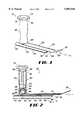
- FIG. 1is a front perspective view of the preferred embodiment of the present invention.
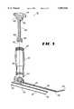
- FIG. 2is a side cross-sectional view of FIG. 1.
- FIG. 3is an exploded side cross-sectional view of FIG. 1.
- the present inventioncomprises a retractor 10 having a longitudinally-extending blade 20, a receptacle 30 adapted to support a predetermined surgical instrument (not shown), and a means for movably connecting the receptacle 30 to the blade 20.
- the connecting meansallows the receptacle 30, and supported surgical instrument, to move relative to the blade 20 to a selected one of a plurality of desired positions.
- the connecting meansalso enables movement of the receptacle 30, whenever necessary, such as if the location of the predetermined surgical instrument must be moved to another portion of the body cavity during the surgery.
- the retractor 10preferably further comprises a means for detachably locking the receptacle 30 at the selected desired position.
- the selected desired positioncan be, for example, the position in which the endoscope is focused on the surgical site.
- retractor 10 of the present inventionis for preforming breast augmentation or reduction surgical procedures.
- the retractor 10can be used for other operations, such as abdominal surgery, lysis of intra-uterine adhesions or other thoracic adhesions, and the like.
- the retractor 10is particularly advantageous when using endoscopic visualization, in which the predetermined surgical instrument is a combined endoscope and light source supported by the receptacle 30.
- the blade 20 of the retractor 10has a longitudinal axis L, a top surface 22, a bottom surface 24, a distal end 26, an opposed proximal end 28, and an edge 29 circumscribing it.
- the preferred material to construct the retractor 10is a stainless steel or a biocompatable alloy that is acceptable for surgery. However, other materials are also contemplated, such as plastic.
- the preferred length of the blade 20 extending between the distal and proximal ends 26, 28can vary depending on the specific surgical site and the size of the patient on whom the procedure is performed.
- the length of the blade 20can be approximately eight (8) inches for an adult patient and about four inches for a pediatric operation occurring at the same respective location.
- the dimensions of the blade 20, such as length, width, and thicknesscan be designed for different, specific surgical procedures. Design considerations include the surgical procedure being performed, the required structural strength, the desired flexibility of the blade 20, and the predetermined area of the patient's body where the operation will occur.
- At least a portion of the blade 20is arcuate in cross section. This is preferred because a curved cross section is stronger and more stable than a flat profile.
- a blade 20 that is substantially rectangular in cross sectionis contemplated as an alternate embodiment.
- the edge 29 of the blade 20 immediately adjacent its distal end 26, or front tipis arcuate.
- the edge 29 of the front tiphas a constant curvature along the edge 29 of the front tip.
- An alternate embodimentis more blunt, such as a front tip having a squared "C" shape (not shown) in which there is not a constant curvature along the front tip.
- the edge 29 of the front tipitself should be smooth and blunt--as opposed to having sharp corners--to reduce the chances of tissue damage or other injuries when used during the surgical procedure.
- the blunt shape of the blade 20can be used to repel tissue away from any areas of adhesiolysis and prevent trauma to the tissue.
- the retractor 10is preferably designed for endoscopic use and includes the receptacle 30 for supporting a predetermined surgical instrument.
- the receptacle 30is preferably disposed adjacent the bottom surface 24 of the blade 20.
- the preferred receptacle 30comprises a longitudinally-extending tube 32 defining a passage 33 therethrough.
- the passage 33is of a size to allow the predetermined endoscopic instrument to be slidably received therein.
- the diameter of the passage 33is of an appropriate dimension to accommodate a particular endoscope or surgical instrument, such as a four (4) or five (5) millimeter diameter for standard endoscopic procedures, or a two (2) or three (3) millimeter diameter for pediatric surgery.
- the tube 32has an insertion end 34 disposed adjacent the proximal end 28 of the blade 20, an opposed operating end 36.
- the predetermined surgical instrumentis slidably disposed into the insertion end 34, through the passage 33, and protrudes from (e.g., when using a cutting instrument) or is aligned with (e.g., when using an endoscope) the operating end 36.
- the operating end 36 of the tube 32forms an angle ⁇ relative to the normal N, or a perpendicular axis, to the longitudinal axis L or the bottom surface 24 of the blade 20.
- a top outer surface 38 of the tube 32 at the operating end 36is longer than a bottom outer surface 39 so that an angle ⁇ exists relative to vertical, preferably an angle ⁇ of thirty degrees (30°).
- Other angles ⁇can be used, but thirty degrees has been found acceptable because the endoscope provides an approximately thirty degree angle (30°) view below horizontal on the video monitor with this angle ⁇ of thirty degrees (30°).
- the retractor 10also preferably further comprises a handle 40 having a first end 42 and an opposed second end 44.
- the second end 44 of the handle 40is attached to the top surface 22 of the blade 20 adjacent its proximal end 28.
- the attachment of the blade 20 to the handle 40may be accomplished by a permanent weld, or, as shown in FIG. 2, the blade may be connected by threads 47 on the interior of handle 40 and complementary threads 27 on the blade 20. In this way, while the blade 20 may be in a fixed position with respect to the handle 40, it may be replaced with another blade, if desired.
- the handle 40defines a bore 46 extending therethrough extending from the first end 42 to the second end 44.
- the blade 20also has an aperture near its proximal end 28 aligned, or in registry, with the bore 46 second end 44 of the handle 40.
- the preferred connecting meanscomprises a ball 50 disposed within the bore 46 of the handle 40 adjacent its second end 44.
- a portion of the ball 50is fixedly attached to a portion of the receptacle 30.
- the ball 50is movably secured within the bore 46 so that the ball 50 and attached receptacle 30 are movable relative to the blade 20 without separating therefrom.
- the ball 50is movably secured because the opening through the blade 20 or the second end 44 of the handle 40 is smaller than the widest dimension of the ball 50. Accordingly, the ball 50 can rotate, pivot, or otherwise move within the bore 46 of the handle 40, but not traverse through the opening in the blade 20.
- the ball 50 and the receptacle 30are attached to each other by a connecting member 52.
- the connecting member 52has opposed ends 54, 56, in which one end 54 is fixedly attached to the ball 50 and the opposed end 56 is fixedly attached to the receptacle 30.
- a portion of the connecting member 52can be threaded (not shown) and complementarily received in a threaded hole (not shown) in the ball 50 to facilitate the assembly of the retractor 10 by joining the connecting member 52 to the ball 50 when the ball 50 is disposed within the bore 46 of the handle 40.
- One locking means of the present inventioncomprises a shaft 60 and a means for adjustably positioning the shaft 60 within the bore 46 between an engaged position and a disengaged position.
- the shaft 60has an upper end 62 and an opposite lower end 64 and at least a portion of the shaft 60 is complementarily received within the bore 46.
- the lower end 64is sized to complementarily and detachably engage a portion of the ball 50, specifically the upper portion.
- the lower end 64 of the shaft 60detachably engages the ball 50 to frictionally hold the ball 50 and, when in the disengaged position, the lower end 64 of the shaft 60 and the ball 50 are spaced apart so that the ball 50 is movable.
- the lower end 64 of the shaft 60 and ball 50do not need to be completely spaced apart to be in the disengaged position, but, instead, may be sufficiently separated to allow movement therebetween. That is, in the disengaged position, the lower end 64 of the shaft 60 and the ball 50 are adequately physically separated, or disengaged, so that the lower end 64 does not frictionally hold or lock the ball 50 in a non-movable position.
- FIG. 2Another embodiment of the locking means shown in FIG. 2 includes a socket 66 that is attached to or contacted by the lower end 64 of the shaft 60.
- the socket 66has an interior surface 68 of a size to complementarily engage an upper portion of the ball 50.
- the interior surface 68 of the socket 66detachably engages the ball 50 to frictionally hold the ball 50, instead of the lower end 64 of the shaft 60. That is, the lower end 64 of the shaft 60 is either attached to or pushes against the socket 66 causing the interior surface 68 to engage the ball 50.
- These shaft 60 designsare considered interchangeable and a primary consideration in deciding which to use is manufacturing costs.
- the means for positioning the shaft 60also comprises a portion of the bore 46 complementarily engaging a portion of the shaft 60.
- the interface between the bore 46 and shaft 60thereby controls the relative movement therebetween as the shaft 60 is moved within the bore 46.
- the portions of the bore 46 and the shaft 60 that engage each otherare complementarily threaded surfaces 69, although other embodiments may be used, such as a protrusion (not shown) on the shaft 60 that traverses along a groove (not shown) formed in the bore 46 to maintain the shaft 60 in a selected one of the engaged or the disengaged positions.
- the shaft 60further comprises a tightener 70 fixedly attached to the upper end 62 of the shaft 60 and disposed outside the bore 46. Rotation of the tightener 70 causes the shaft 60 (and separate socket 66 if used) to move between the engaged and disengaged positions, depending on the direction of rotation, because of the complementarily threaded surfaces 69 of the shaft 60 and bore 46 engaging each other.
- the tightener 70also preferably has a plurality of notches 72 on its periphery therein to assist rotation of the tightener 70. The notches 72 are of a size to engage a portion of one of the surgeon's fingers.
- the surgical instrumentuse a compression fitting to be secured to the insertion end 34 of the tube 32.
- a compression fittingallows longitudinal movement of the surgical instrument along the passage 33 of the tube 32 when the surgeon applies sufficient force.
- a bayonet-type endoscopic fitting(not shown) is another contemplated fitting formed at the insertion end 34 of the tube 32 to secure the predetermined surgical instrument at a desired position in the tube 32.
- Other securing devices known in the artcan similarly be used. It is contemplated that the surgical instruments can be switched during the surgical procedure while stationarily maintaining the blade 20 at the surgical site, e.g,, switching a suction instrument with an endoscope and vice versa.
- the surgeongripping the handle 40 of the retractor 10, starts the procedure by placing distal end 26 of the blade 20 into the body cavity where the surgical procedure will be performed.
- the endoscopic surgical instrumentspecifically the endoscope in this example, is disposed within the receptacle 30 (which is locked in its initial position) and the surgeon views the video monitor while positioning the distal end 26 of the blade 20.
- the surgeoncan, if desired, rotate the tightener 70 using his thumb so that the ball 50 and socket 66 are in the disengaged position.
- the surgeoncan grab the insertion end 34 of the tube 32 or a portion of the endoscope to move the tube 32 and orient the camera.
- the ball 50 connectionallows a great freedom of movement (e.g., up and down, side to side, and a combination thereof) relative to the blade 20.
- This process of redirecting the endoscopeoccurs while the blade 20 of the retractor 10 remains stationary or, alternatively, the surgeon can move the blade 20 also.
- the surgeoncan repeat the same actions throughout the surgical procedure whenever he desires to remove the endoscope (or other surgical instrument) being used.
- thisis one example of use of the present invention and, as persons skilled in the art will appreciate, many other methods of using of the present invention exist.
Landscapes
- Health & Medical Sciences (AREA)
- Life Sciences & Earth Sciences (AREA)
- Surgery (AREA)
- General Health & Medical Sciences (AREA)
- Veterinary Medicine (AREA)
- Biomedical Technology (AREA)
- Heart & Thoracic Surgery (AREA)
- Medical Informatics (AREA)
- Molecular Biology (AREA)
- Animal Behavior & Ethology (AREA)
- Nuclear Medicine, Radiotherapy & Molecular Imaging (AREA)
- Public Health (AREA)
- Engineering & Computer Science (AREA)
- Pathology (AREA)
- Physics & Mathematics (AREA)
- Biophysics (AREA)
- Optics & Photonics (AREA)
- Radiology & Medical Imaging (AREA)
- Oral & Maxillofacial Surgery (AREA)
- Surgical Instruments (AREA)
- Endoscopes (AREA)
Abstract
Description
Claims (16)
Priority Applications (2)
| Application Number | Priority Date | Filing Date | Title |
|---|---|---|---|
| US08/934,626US5891018A (en) | 1997-09-19 | 1997-09-19 | Ball joint retractor |
| US09/169,683US5904650A (en) | 1997-09-19 | 1998-10-09 | Ball joint retractor |
Applications Claiming Priority (1)
| Application Number | Priority Date | Filing Date | Title |
|---|---|---|---|
| US08/934,626US5891018A (en) | 1997-09-19 | 1997-09-19 | Ball joint retractor |
Related Child Applications (1)
| Application Number | Title | Priority Date | Filing Date |
|---|---|---|---|
| US09/169,683ContinuationUS5904650A (en) | 1997-09-19 | 1998-10-09 | Ball joint retractor |
Publications (1)
| Publication Number | Publication Date |
|---|---|
| US5891018Atrue US5891018A (en) | 1999-04-06 |
Family
ID=25465828
Family Applications (2)
| Application Number | Title | Priority Date | Filing Date |
|---|---|---|---|
| US08/934,626Expired - LifetimeUS5891018A (en) | 1997-09-19 | 1997-09-19 | Ball joint retractor |
| US09/169,683Expired - LifetimeUS5904650A (en) | 1997-09-19 | 1998-10-09 | Ball joint retractor |
Family Applications After (1)
| Application Number | Title | Priority Date | Filing Date |
|---|---|---|---|
| US09/169,683Expired - LifetimeUS5904650A (en) | 1997-09-19 | 1998-10-09 | Ball joint retractor |
Country Status (1)
| Country | Link |
|---|---|
| US (2) | US5891018A (en) |
Cited By (23)
| Publication number | Priority date | Publication date | Assignee | Title |
|---|---|---|---|---|
| US6254535B1 (en)* | 1996-04-26 | 2001-07-03 | Genzyme Corporation | Ball and socket coronary stabilizer |
| US6551242B1 (en)* | 1996-04-26 | 2003-04-22 | Genzyme Corporation | Retractor-mounted coronary stabilizer |
| US20040143164A1 (en)* | 2003-01-17 | 2004-07-22 | Loubert Suddaby | Laminectomy suction and retraction device |
| WO2006102770A1 (en)* | 2005-04-01 | 2006-10-05 | Saturn Biomedical Systems Inc. | Video retractor |
| US20080076968A1 (en)* | 2006-05-19 | 2008-03-27 | Zemco Manufacturing Inc. | Surgical tool |
| USD574493S1 (en) | 2007-06-22 | 2008-08-05 | Vioptix, Inc. | Portion of nerve root retractor with sensor |
| USD574955S1 (en) | 2007-06-22 | 2008-08-12 | Vioptix, Inc. | Portion of nerve root retractor with sensor |
| USD575398S1 (en) | 2007-12-05 | 2008-08-19 | Vioptix, Inc. | Portion of a surgical elevator with sensor |
| USD578647S1 (en) | 2007-12-05 | 2008-10-14 | Vioptix, Inc. | Portion of a surgical retractor with sensor |
| USD582034S1 (en) | 2007-06-22 | 2008-12-02 | Vioptix, Inc. | Portion of nerve root retractor with sensor |
| US20080319290A1 (en)* | 2007-06-22 | 2008-12-25 | Vioptix, Inc. | Tissue Retractor Oximeter |
| US20090149715A1 (en)* | 2007-12-05 | 2009-06-11 | Vioptix, Inc. | Surgical Elevator Oximeter |
| US20090292187A1 (en)* | 2008-05-24 | 2009-11-26 | Vioptix Inc. | Device for Assessing Ischemia in Nerve Root Tissue Using Oxygen Saturation |
| USD621937S1 (en)* | 2009-03-23 | 2010-08-17 | Karl Storz Gmbh & Co. Kg | Retractor with optic shaft |
| USD631963S1 (en)* | 2009-07-14 | 2011-02-01 | Karl Storz Gmbh & Co. Kg | Laryngoscope |
| US20110082375A1 (en)* | 2009-10-02 | 2011-04-07 | Eastern Virginia Medical School | Transvaginal ultrasound probe speculum |
| DE102010049759A1 (en)* | 2010-10-29 | 2012-05-03 | Karl Storz Gmbh & Co. Kg | Device for manual retraction of muscle or for lifting another organ, has spatula device for rear driving of muscle or organ, handle and joint provided between proximal end of spatula device and handle |
| USD675319S1 (en)* | 2009-12-22 | 2013-01-29 | Karl Storz Gmbh & Co. Kg | Spreadable mediastinoscope |
| US20140316206A1 (en)* | 2010-07-30 | 2014-10-23 | Nilesh R. Vasan | Disposable, self-contained laryngoscope and method of using same |
| US9066692B1 (en) | 2009-06-03 | 2015-06-30 | Vioptix, Inc. | Medical device probe connector |
| USD742512S1 (en)* | 2013-10-16 | 2015-11-03 | Karl Storz Gmbh & Co. Kg | Spreadable laryngoscope |
| CN109925009A (en)* | 2017-12-15 | 2019-06-25 | 中国人民解放军第二军医大学 | Regulating device and surgical instrument for surgical instrument |
| USD876625S1 (en) | 2018-08-07 | 2020-02-25 | Adroit Surgical, Llc | Laryngoscope |
Families Citing this family (23)
| Publication number | Priority date | Publication date | Assignee | Title |
|---|---|---|---|---|
| US6228025B1 (en) | 1998-05-01 | 2001-05-08 | Genzyme Corporation | Illuminated saphenous vein retractor |
| US6585727B1 (en) | 1999-10-22 | 2003-07-01 | Genzyme Corporation | Surgical instrument light source and surgical illumination method |
| US6322499B1 (en) | 2000-01-20 | 2001-11-27 | Genzyme Corporation | Pivotal and illuminated saphenous vein retractor |
| US6497654B1 (en) | 2000-02-18 | 2002-12-24 | Genzyme Corporation | Illuminated rectal retractor |
| US6428473B1 (en) | 2000-02-18 | 2002-08-06 | Genzyme Corporation | Illuminated rectal retractor |
| US6454704B1 (en)* | 2000-06-13 | 2002-09-24 | Mark Dzworkiewicz | Lifting cap for a laryngoscope |
| AU2001280476B2 (en) | 2000-06-30 | 2005-11-24 | Stephen Ritland | Polyaxial connection device and method |
| US6554768B1 (en) | 2000-09-05 | 2003-04-29 | Genzyme Corporation | Illuminated deep pelvic retractor |
| DE60238997D1 (en)* | 2001-09-28 | 2011-03-03 | Stephen Ritland | CHROME OR HOOKS |
| US6817978B2 (en) | 2002-01-23 | 2004-11-16 | Teleflex-Ct Devices Incorporated | Illuminated retractor for use in connection with harvesting a blood vessel from the arm |
| ATE476930T1 (en) | 2002-02-20 | 2010-08-15 | Stephen Ritland | DEVICE FOR CONNECTING HAND SCREWS |
| US6966910B2 (en) | 2002-04-05 | 2005-11-22 | Stephen Ritland | Dynamic fixation device and method of use |
| ATE552789T1 (en) | 2002-05-08 | 2012-04-15 | Stephen Ritland | DYNAMIC FIXATION DEVICE |
| US6805666B2 (en) | 2002-05-23 | 2004-10-19 | Donna D. Holland | Pivotal and illuminated saphenous vein retractor with tapered design |
| US7766825B2 (en)* | 2002-10-02 | 2010-08-03 | Synthes Usa, Llc | Retractor with interchangeable retractor blades |
| EP1596738A4 (en)* | 2003-02-25 | 2010-01-20 | Stephen Ritland | Adjustable rod and connector device and method of use |
| WO2004110247A2 (en) | 2003-05-22 | 2004-12-23 | Stephen Ritland | Intermuscular guide for retractor insertion and method of use |
| US7455639B2 (en)* | 2004-09-20 | 2008-11-25 | Stephen Ritland | Opposing parallel bladed retractor and method of use |
| JP4988735B2 (en) | 2005-07-19 | 2012-08-01 | リットランド、ステファン | Rod extension for elongating fusion structures |
| US7959564B2 (en)* | 2006-07-08 | 2011-06-14 | Stephen Ritland | Pedicle seeker and retractor, and methods of use |
| US8216132B2 (en)* | 2008-05-30 | 2012-07-10 | Dzwonkiewicz Mark R | Gear-shaped lifting cap for a laryngoscope |
| CN101933823B (en)* | 2010-09-17 | 2012-10-03 | 申屠丙花 | Universal draw hook for human body operation |
| CN103767762B (en)* | 2014-01-13 | 2015-09-30 | 上海市肺科医院 | The lymph node surrounding tissue be applied in single hole thoracoscope radical resection of pulmonary carcinoma pushes pincers open |
Citations (37)
| Publication number | Priority date | Publication date | Assignee | Title |
|---|---|---|---|---|
| US2670732A (en)* | 1952-08-11 | 1954-03-02 | Ole A Nelson | Surgical retractor |
| US2693795A (en)* | 1950-09-09 | 1954-11-09 | Herman R Grieshaber | Surgical retractor |
| US2756742A (en)* | 1953-08-18 | 1956-07-31 | Barton Foundation | Endotracheal tongue blade with tube guide |
| US2863444A (en)* | 1956-08-21 | 1958-12-09 | Winsten Joseph | Liver retractor for cholecystectomies |
| US3030948A (en)* | 1960-08-17 | 1962-04-24 | Jacob F Loeffler | Adjustable surgical retractor |
| US3196865A (en)* | 1963-02-06 | 1965-07-27 | Avco Corp | Self-retaining retractor |
| US3221743A (en)* | 1962-08-13 | 1965-12-07 | Pa Co Inc Du | System and apparatus for positioning and securing surgical implements |
| US3320948A (en)* | 1964-06-24 | 1967-05-23 | Dept Of Obstetrics And Gynecol | Positioning instrument clamp for use with speculum |
| US3409013A (en)* | 1965-08-23 | 1968-11-05 | Berry Henry | Instrument for inserting artificial heart valves |
| US3467079A (en)* | 1967-04-14 | 1969-09-16 | David Charles James | Gall bladder and common duct retractor |
| US3882855A (en)* | 1973-11-12 | 1975-05-13 | Heyer Schulte Corp | Retractor for soft tissue for example brain tissue |
| US4050464A (en)* | 1975-04-28 | 1977-09-27 | Downs Surgical Limited | Surgical cable tensioning instrument |
| US4052980A (en)* | 1976-06-10 | 1977-10-11 | Guenter A. Grams | Triaxial fiberoptic soft tissue retractor |
| US4151838A (en)* | 1977-06-17 | 1979-05-01 | Crew John R | Internal mammary artery sternal retractor |
| US4323057A (en)* | 1980-05-27 | 1982-04-06 | Jamieson David J | Self retaining uterine elevator |
| US4457300A (en)* | 1982-06-07 | 1984-07-03 | Ohio Medical Instrument Co., Inc. | Surgical retractor |
| US4616634A (en)* | 1985-03-07 | 1986-10-14 | Commonwealth Of Puerto Rico | Soft tissue protector for use in oral and maxillofacial surgery |
| US4905670A (en)* | 1988-12-28 | 1990-03-06 | Adair Edwin Lloyd | Apparatus for cervical videoscopy |
| US4949707A (en)* | 1984-11-08 | 1990-08-21 | Minnesota Scientific, Inc. | Retractor apparatus |
| GB2233561A (en)* | 1989-07-07 | 1991-01-16 | Engineering In Medicine Limite | Workpiece holding or positioning means |
| US5133724A (en)* | 1991-04-04 | 1992-07-28 | Pilling Co. | Abdominal aortic clamp |
| US5167223A (en)* | 1989-09-08 | 1992-12-01 | Tibor Koros | Heart valve retractor and sternum spreader surgical instrument |
| US5201325A (en)* | 1989-09-01 | 1993-04-13 | Andronic Devices Ltd. | Advanced surgical retractor |
| US5318013A (en)* | 1992-11-06 | 1994-06-07 | Wilk Peter J | Surgical clamping assembly and associated method |
| US5337736A (en)* | 1992-09-30 | 1994-08-16 | Reddy Pratap K | Method of using a laparoscopic retractor |
| US5429118A (en)* | 1994-04-07 | 1995-07-04 | Cook (Canada) Incorporated | Disposable medical scope sheath |
| US5449374A (en)* | 1993-04-01 | 1995-09-12 | University Of Massachusetts Medical Center | Tissue spreading forceps |
| US5458595A (en)* | 1993-12-16 | 1995-10-17 | The Regents Of The University Of California | Vaginal speculum for photodynamic therapy and method of using the same |
| US5498256A (en)* | 1993-05-28 | 1996-03-12 | Snowden-Pencer, Inc. | Surgical instrument handle |
| US5509890A (en)* | 1993-12-16 | 1996-04-23 | Kazama; Shigeru | Heart retractor |
| US5512037A (en)* | 1994-05-12 | 1996-04-30 | United States Surgical Corporation | Percutaneous surgical retractor |
| US5514076A (en)* | 1994-01-27 | 1996-05-07 | Flexmedics Corporation | Surgical retractor |
| US5514077A (en)* | 1994-07-05 | 1996-05-07 | Rabban; Philipp | Surgical retractor |
| US5529571A (en)* | 1995-01-17 | 1996-06-25 | Daniel; Elie C. | Surgical retractor/compressor |
| US5554101A (en)* | 1991-08-05 | 1996-09-10 | United States Surgical Corporation | Surgical retractor |
| US5558621A (en)* | 1995-04-24 | 1996-09-24 | Heil Associates Inc. | Surgical retractor with cross bar grips |
| US5588951A (en)* | 1993-01-19 | 1996-12-31 | Loma Linda University Medical Center | Inflatable endoscopic retractor with multiple rib-reinforced projections |
- 1997
- 1997-09-19USUS08/934,626patent/US5891018A/ennot_activeExpired - Lifetime
- 1998
- 1998-10-09USUS09/169,683patent/US5904650A/ennot_activeExpired - Lifetime
Patent Citations (37)
| Publication number | Priority date | Publication date | Assignee | Title |
|---|---|---|---|---|
| US2693795A (en)* | 1950-09-09 | 1954-11-09 | Herman R Grieshaber | Surgical retractor |
| US2670732A (en)* | 1952-08-11 | 1954-03-02 | Ole A Nelson | Surgical retractor |
| US2756742A (en)* | 1953-08-18 | 1956-07-31 | Barton Foundation | Endotracheal tongue blade with tube guide |
| US2863444A (en)* | 1956-08-21 | 1958-12-09 | Winsten Joseph | Liver retractor for cholecystectomies |
| US3030948A (en)* | 1960-08-17 | 1962-04-24 | Jacob F Loeffler | Adjustable surgical retractor |
| US3221743A (en)* | 1962-08-13 | 1965-12-07 | Pa Co Inc Du | System and apparatus for positioning and securing surgical implements |
| US3196865A (en)* | 1963-02-06 | 1965-07-27 | Avco Corp | Self-retaining retractor |
| US3320948A (en)* | 1964-06-24 | 1967-05-23 | Dept Of Obstetrics And Gynecol | Positioning instrument clamp for use with speculum |
| US3409013A (en)* | 1965-08-23 | 1968-11-05 | Berry Henry | Instrument for inserting artificial heart valves |
| US3467079A (en)* | 1967-04-14 | 1969-09-16 | David Charles James | Gall bladder and common duct retractor |
| US3882855A (en)* | 1973-11-12 | 1975-05-13 | Heyer Schulte Corp | Retractor for soft tissue for example brain tissue |
| US4050464A (en)* | 1975-04-28 | 1977-09-27 | Downs Surgical Limited | Surgical cable tensioning instrument |
| US4052980A (en)* | 1976-06-10 | 1977-10-11 | Guenter A. Grams | Triaxial fiberoptic soft tissue retractor |
| US4151838A (en)* | 1977-06-17 | 1979-05-01 | Crew John R | Internal mammary artery sternal retractor |
| US4323057A (en)* | 1980-05-27 | 1982-04-06 | Jamieson David J | Self retaining uterine elevator |
| US4457300A (en)* | 1982-06-07 | 1984-07-03 | Ohio Medical Instrument Co., Inc. | Surgical retractor |
| US4949707A (en)* | 1984-11-08 | 1990-08-21 | Minnesota Scientific, Inc. | Retractor apparatus |
| US4616634A (en)* | 1985-03-07 | 1986-10-14 | Commonwealth Of Puerto Rico | Soft tissue protector for use in oral and maxillofacial surgery |
| US4905670A (en)* | 1988-12-28 | 1990-03-06 | Adair Edwin Lloyd | Apparatus for cervical videoscopy |
| GB2233561A (en)* | 1989-07-07 | 1991-01-16 | Engineering In Medicine Limite | Workpiece holding or positioning means |
| US5201325A (en)* | 1989-09-01 | 1993-04-13 | Andronic Devices Ltd. | Advanced surgical retractor |
| US5167223A (en)* | 1989-09-08 | 1992-12-01 | Tibor Koros | Heart valve retractor and sternum spreader surgical instrument |
| US5133724A (en)* | 1991-04-04 | 1992-07-28 | Pilling Co. | Abdominal aortic clamp |
| US5554101A (en)* | 1991-08-05 | 1996-09-10 | United States Surgical Corporation | Surgical retractor |
| US5337736A (en)* | 1992-09-30 | 1994-08-16 | Reddy Pratap K | Method of using a laparoscopic retractor |
| US5318013A (en)* | 1992-11-06 | 1994-06-07 | Wilk Peter J | Surgical clamping assembly and associated method |
| US5588951A (en)* | 1993-01-19 | 1996-12-31 | Loma Linda University Medical Center | Inflatable endoscopic retractor with multiple rib-reinforced projections |
| US5449374A (en)* | 1993-04-01 | 1995-09-12 | University Of Massachusetts Medical Center | Tissue spreading forceps |
| US5498256A (en)* | 1993-05-28 | 1996-03-12 | Snowden-Pencer, Inc. | Surgical instrument handle |
| US5458595A (en)* | 1993-12-16 | 1995-10-17 | The Regents Of The University Of California | Vaginal speculum for photodynamic therapy and method of using the same |
| US5509890A (en)* | 1993-12-16 | 1996-04-23 | Kazama; Shigeru | Heart retractor |
| US5514076A (en)* | 1994-01-27 | 1996-05-07 | Flexmedics Corporation | Surgical retractor |
| US5429118A (en)* | 1994-04-07 | 1995-07-04 | Cook (Canada) Incorporated | Disposable medical scope sheath |
| US5512037A (en)* | 1994-05-12 | 1996-04-30 | United States Surgical Corporation | Percutaneous surgical retractor |
| US5514077A (en)* | 1994-07-05 | 1996-05-07 | Rabban; Philipp | Surgical retractor |
| US5529571A (en)* | 1995-01-17 | 1996-06-25 | Daniel; Elie C. | Surgical retractor/compressor |
| US5558621A (en)* | 1995-04-24 | 1996-09-24 | Heil Associates Inc. | Surgical retractor with cross bar grips |
Non-Patent Citations (2)
| Title |
|---|
| Aesculap General Surgical Catalogue (C 214730), Feb. 1983 (4 pages).* |
| Aesculap® General Surgical Catalogue (C-214730), Feb. 1983 (4 pages). |
Cited By (50)
| Publication number | Priority date | Publication date | Assignee | Title |
|---|---|---|---|---|
| US6254535B1 (en)* | 1996-04-26 | 2001-07-03 | Genzyme Corporation | Ball and socket coronary stabilizer |
| US6379297B1 (en)* | 1996-04-26 | 2002-04-30 | Genzyme Corporation | Ball and socket coronary stabilizer |
| US6551242B1 (en)* | 1996-04-26 | 2003-04-22 | Genzyme Corporation | Retractor-mounted coronary stabilizer |
| US20040143164A1 (en)* | 2003-01-17 | 2004-07-22 | Loubert Suddaby | Laminectomy suction and retraction device |
| WO2004064746A3 (en)* | 2003-01-17 | 2004-10-28 | Loubert Suddaby | Laminectomy suction and retraction device |
| US6875173B2 (en)* | 2003-01-17 | 2005-04-05 | Loubert Suddaby | Laminectomy suction and retraction device |
| AU2004206908B2 (en)* | 2003-01-17 | 2007-08-23 | Loubert Suddaby | Laminectomy suction and retraction device |
| WO2006102770A1 (en)* | 2005-04-01 | 2006-10-05 | Saturn Biomedical Systems Inc. | Video retractor |
| US20060276693A1 (en)* | 2005-04-01 | 2006-12-07 | Pacey John A | Video rectractor |
| CN101175436B (en)* | 2005-04-01 | 2011-01-26 | 维拉顿医疗(加拿大)Ulc公司 | Video retractor |
| US8187180B2 (en)* | 2005-04-01 | 2012-05-29 | Verathon Medical (Canada) Ulc | Video rectractor |
| US20080076968A1 (en)* | 2006-05-19 | 2008-03-27 | Zemco Manufacturing Inc. | Surgical tool |
| USD574493S1 (en) | 2007-06-22 | 2008-08-05 | Vioptix, Inc. | Portion of nerve root retractor with sensor |
| US12097026B2 (en) | 2007-06-22 | 2024-09-24 | Vioptix, Inc. | Tissue retractor oximeter |
| USD582034S1 (en) | 2007-06-22 | 2008-12-02 | Vioptix, Inc. | Portion of nerve root retractor with sensor |
| US20080319290A1 (en)* | 2007-06-22 | 2008-12-25 | Vioptix, Inc. | Tissue Retractor Oximeter |
| US11452471B2 (en) | 2007-06-22 | 2022-09-27 | Vioptix, Inc. | Tissue retractor oximeter |
| US10178968B2 (en) | 2007-06-22 | 2019-01-15 | Vioptix, Inc. | Tissue retractor oximeter |
| US9380966B2 (en) | 2007-06-22 | 2016-07-05 | Vioptix, Inc. | Tissue retractor oximeter |
| USD615198S1 (en) | 2007-06-22 | 2010-05-04 | Vioptix Inc. | Portion of nerve root retractor with sensor |
| USD621041S1 (en) | 2007-06-22 | 2010-08-03 | Vioptix Inc. | Portion of nerve root retractor with sensor |
| USD574955S1 (en) | 2007-06-22 | 2008-08-12 | Vioptix, Inc. | Portion of nerve root retractor with sensor |
| USD575398S1 (en) | 2007-12-05 | 2008-08-19 | Vioptix, Inc. | Portion of a surgical elevator with sensor |
| US12029556B2 (en) | 2007-12-05 | 2024-07-09 | Vioptix, Inc. | Surgical elevator oximeter |
| USD633614S1 (en) | 2007-12-05 | 2011-03-01 | Vioptix Inc. | Portion of surgical retractor with sensor |
| US10849535B2 (en) | 2007-12-05 | 2020-12-01 | Vioptix, Inc. | Surgical elevator oximeter |
| USD578647S1 (en) | 2007-12-05 | 2008-10-14 | Vioptix, Inc. | Portion of a surgical retractor with sensor |
| US20090149715A1 (en)* | 2007-12-05 | 2009-06-11 | Vioptix, Inc. | Surgical Elevator Oximeter |
| US12048532B2 (en) | 2007-12-05 | 2024-07-30 | Vioptix, Inc. | Surgical elevator oximeter |
| USD593201S1 (en) | 2007-12-05 | 2009-05-26 | Vioptix, Inc. | Portion of surgical elevator with sensor |
| US20090292187A1 (en)* | 2008-05-24 | 2009-11-26 | Vioptix Inc. | Device for Assessing Ischemia in Nerve Root Tissue Using Oxygen Saturation |
| US9031628B2 (en) | 2008-05-24 | 2015-05-12 | Vioptix, Inc. | Device for assessing ischemia in nerve root tissue using oxygen saturation |
| USD621937S1 (en)* | 2009-03-23 | 2010-08-17 | Karl Storz Gmbh & Co. Kg | Retractor with optic shaft |
| US9066692B1 (en) | 2009-06-03 | 2015-06-30 | Vioptix, Inc. | Medical device probe connector |
| US11375925B1 (en) | 2009-06-03 | 2022-07-05 | Vioptix, Inc. | Medical device probe and connector |
| US10357190B1 (en) | 2009-06-03 | 2019-07-23 | Vioptix, Inc. | Medical device probe and connector |
| US9579051B1 (en) | 2009-06-03 | 2017-02-28 | Vioptix, Inc. | Medical device probe and connector |
| US12171553B1 (en) | 2009-06-03 | 2024-12-24 | Vioptix, Inc. | Medical device probe and connector |
| USD631963S1 (en)* | 2009-07-14 | 2011-02-01 | Karl Storz Gmbh & Co. Kg | Laryngoscope |
| US8403842B2 (en)* | 2009-10-02 | 2013-03-26 | Eastern Virgina Medical School | Transvaginal ultrasound probe speculum |
| US20110082375A1 (en)* | 2009-10-02 | 2011-04-07 | Eastern Virginia Medical School | Transvaginal ultrasound probe speculum |
| USD675319S1 (en)* | 2009-12-22 | 2013-01-29 | Karl Storz Gmbh & Co. Kg | Spreadable mediastinoscope |
| US20190254511A1 (en)* | 2010-07-30 | 2019-08-22 | Adroit Surgical Llc | Disposable, self-contained laryngoscope and method of using same |
| US9289114B2 (en)* | 2010-07-30 | 2016-03-22 | Nilesh R. Vasan | Disposable, self-contained laryngoscope and method of using same |
| US11478139B2 (en)* | 2010-07-30 | 2022-10-25 | Adroit Surgical, Llc | Disposable, self-contained laryngoscope and method of using same |
| US20140316206A1 (en)* | 2010-07-30 | 2014-10-23 | Nilesh R. Vasan | Disposable, self-contained laryngoscope and method of using same |
| DE102010049759A1 (en)* | 2010-10-29 | 2012-05-03 | Karl Storz Gmbh & Co. Kg | Device for manual retraction of muscle or for lifting another organ, has spatula device for rear driving of muscle or organ, handle and joint provided between proximal end of spatula device and handle |
| USD742512S1 (en)* | 2013-10-16 | 2015-11-03 | Karl Storz Gmbh & Co. Kg | Spreadable laryngoscope |
| CN109925009A (en)* | 2017-12-15 | 2019-06-25 | 中国人民解放军第二军医大学 | Regulating device and surgical instrument for surgical instrument |
| USD876625S1 (en) | 2018-08-07 | 2020-02-25 | Adroit Surgical, Llc | Laryngoscope |
Also Published As
| Publication number | Publication date |
|---|---|
| US5904650A (en) | 1999-05-18 |
Similar Documents
| Publication | Publication Date | Title |
|---|---|---|
| US5891018A (en) | Ball joint retractor | |
| US8337398B2 (en) | Medical instrument | |
| US6193650B1 (en) | Shielded illumination device for ophthalmic surgery and the like | |
| US9320506B2 (en) | Retractor system for anterior cervical spine surgery | |
| US5813976A (en) | Stabilizing instrumentation for the performing of endoscopic surgical procedures | |
| EP0920280B1 (en) | Fingertip-mounted minimally invasive surgical instruments | |
| US6096026A (en) | Surgical instruments for minimally invasive surgical procedures | |
| US20070244515A1 (en) | Multipurpose Surgical Tool | |
| US20090131751A1 (en) | Anal surgical instrument guides | |
| US20050080434A1 (en) | Laparoscopic retractable dissector and suture and needle passer | |
| US20100324375A1 (en) | Laparoscopic instrument and trocar system and related surgical method | |
| US11529040B2 (en) | Endoscope attachment mechanisms and methods of use | |
| CA2220493A1 (en) | Endosurgical instrument with a radially movable end effector | |
| JPH06217987A (en) | Nonexternal wound type endoscope device | |
| US8157832B2 (en) | Blunt dissection and tissue elevation instrument | |
| JP3743512B2 (en) | Surgical mantle | |
| US8911352B2 (en) | Endoscope-holding device and endoscopic system | |
| US20220160347A1 (en) | Endoscopic stitching device for supporting suture needles in various orientations | |
| EP0755659B1 (en) | Surgical instrument holder | |
| US5807235A (en) | Surgical tool holding and positioning device | |
| EP3586764A2 (en) | Surgical retractors | |
| JPH09294746A (en) | Instrument for operation |
Legal Events
| Date | Code | Title | Description |
|---|---|---|---|
| AS | Assignment | Owner name:GENZYME CORPORATION, MASSACHUSETTS Free format text:ASSIGNMENT OF ASSIGNORS INTEREST;ASSIGNOR:WELLS, B. KEITH;REEL/FRAME:009051/0638 Effective date:19980226 | |
| STCF | Information on status: patent grant | Free format text:PATENTED CASE | |
| FEPP | Fee payment procedure | Free format text:PAYOR NUMBER ASSIGNED (ORIGINAL EVENT CODE: ASPN); ENTITY STATUS OF PATENT OWNER: LARGE ENTITY | |
| FPAY | Fee payment | Year of fee payment:4 | |
| FEPP | Fee payment procedure | Free format text:PAYER NUMBER DE-ASSIGNED (ORIGINAL EVENT CODE: RMPN); ENTITY STATUS OF PATENT OWNER: LARGE ENTITY Free format text:PAYOR NUMBER ASSIGNED (ORIGINAL EVENT CODE: ASPN); ENTITY STATUS OF PATENT OWNER: LARGE ENTITY | |
| AS | Assignment | Owner name:SNOWDEN PENCER, INC., GEORGIA Free format text:ASSIGNMENT OF ASSIGNORS INTEREST;ASSIGNOR:GENZYME, CORPORATION;REEL/FRAME:013998/0554 Effective date:20011121 | |
| FPAY | Fee payment | Year of fee payment:8 | |
| FPAY | Fee payment | Year of fee payment:12 | |
| AS | Assignment | Owner name:ALLEGIANCE CORPORATION, ILLINOIS Free format text:MERGER;ASSIGNOR:SNOWDEN-PENCER, INC.;REEL/FRAME:029111/0663 Effective date:20040628 | |
| AS | Assignment | Owner name:CARDINAL HEALTH CMP 200, INC, CALIFORNIA Free format text:ASSIGNMENT OF ASSIGNORS INTEREST;ASSIGNOR:ALLEGIANCE CORPORATION;REEL/FRAME:029124/0517 Effective date:20090817 | |
| AS | Assignment | Owner name:CAREFUSION 2200, INC., CALIFORNIA Free format text:CHANGE OF NAME;ASSIGNOR:CARDINAL HEALTH CMP 200, INC.;REEL/FRAME:029132/0904 Effective date:20090729 |