US5890626A - Remote juice dispenser - Google Patents
Remote juice dispenserDownload PDFInfo
- Publication number
- US5890626A US5890626AUS08/695,619US69561996AUS5890626AUS 5890626 AUS5890626 AUS 5890626AUS 69561996 AUS69561996 AUS 69561996AUS 5890626 AUS5890626 AUS 5890626A
- Authority
- US
- United States
- Prior art keywords
- juice
- dispenser
- water
- dispensing
- concentrate
- Prior art date
- Legal status (The legal status is an assumption and is not a legal conclusion. Google has not performed a legal analysis and makes no representation as to the accuracy of the status listed.)
- Expired - Lifetime
Links
Images


Classifications
- B—PERFORMING OPERATIONS; TRANSPORTING
- B67—OPENING, CLOSING OR CLEANING BOTTLES, JARS OR SIMILAR CONTAINERS; LIQUID HANDLING
- B67D—DISPENSING, DELIVERING OR TRANSFERRING LIQUIDS, NOT OTHERWISE PROVIDED FOR
- B67D1/00—Apparatus or devices for dispensing beverages on draught
- B67D1/08—Details
- B67D1/12—Flow or pressure control devices or systems, e.g. valves, gas pressure control, level control in storage containers
- B67D1/1284—Ratio control
- B67D1/1286—Ratio control by mechanical construction
- B—PERFORMING OPERATIONS; TRANSPORTING
- B67—OPENING, CLOSING OR CLEANING BOTTLES, JARS OR SIMILAR CONTAINERS; LIQUID HANDLING
- B67D—DISPENSING, DELIVERING OR TRANSFERRING LIQUIDS, NOT OTHERWISE PROVIDED FOR
- B67D1/00—Apparatus or devices for dispensing beverages on draught
- B67D1/0015—Apparatus or devices for dispensing beverages on draught the beverage being prepared by mixing at least two liquid components
- B67D1/0021—Apparatus or devices for dispensing beverages on draught the beverage being prepared by mixing at least two liquid components the components being mixed at the time of dispensing, i.e. post-mix dispensers
- B67D1/0022—Apparatus or devices for dispensing beverages on draught the beverage being prepared by mixing at least two liquid components the components being mixed at the time of dispensing, i.e. post-mix dispensers the apparatus comprising means for automatically controlling the amount to be dispensed
- B67D1/0027—Apparatus or devices for dispensing beverages on draught the beverage being prepared by mixing at least two liquid components the components being mixed at the time of dispensing, i.e. post-mix dispensers the apparatus comprising means for automatically controlling the amount to be dispensed control of the amount of one component, the amount of the other components(s) being dependent on that control
- B67D1/0029—Apparatus or devices for dispensing beverages on draught the beverage being prepared by mixing at least two liquid components the components being mixed at the time of dispensing, i.e. post-mix dispensers the apparatus comprising means for automatically controlling the amount to be dispensed control of the amount of one component, the amount of the other components(s) being dependent on that control based on volumetric dosing
- B67D1/003—Apparatus or devices for dispensing beverages on draught the beverage being prepared by mixing at least two liquid components the components being mixed at the time of dispensing, i.e. post-mix dispensers the apparatus comprising means for automatically controlling the amount to be dispensed control of the amount of one component, the amount of the other components(s) being dependent on that control based on volumetric dosing by means of a dosing chamber
- B67D1/0031—Apparatus or devices for dispensing beverages on draught the beverage being prepared by mixing at least two liquid components the components being mixed at the time of dispensing, i.e. post-mix dispensers the apparatus comprising means for automatically controlling the amount to be dispensed control of the amount of one component, the amount of the other components(s) being dependent on that control based on volumetric dosing by means of a dosing chamber in the form of a metering pump
- B—PERFORMING OPERATIONS; TRANSPORTING
- B67—OPENING, CLOSING OR CLEANING BOTTLES, JARS OR SIMILAR CONTAINERS; LIQUID HANDLING
- B67D—DISPENSING, DELIVERING OR TRANSFERRING LIQUIDS, NOT OTHERWISE PROVIDED FOR
- B67D1/00—Apparatus or devices for dispensing beverages on draught
- B67D1/08—Details
- B67D1/0857—Cooling arrangements
- B67D1/0858—Cooling arrangements using compression systems
- B67D1/0861—Cooling arrangements using compression systems the evaporator acting through an intermediate heat transfer means
- B67D1/0864—Cooling arrangements using compression systems the evaporator acting through an intermediate heat transfer means in the form of a cooling bath
- B—PERFORMING OPERATIONS; TRANSPORTING
- B67—OPENING, CLOSING OR CLEANING BOTTLES, JARS OR SIMILAR CONTAINERS; LIQUID HANDLING
- B67D—DISPENSING, DELIVERING OR TRANSFERRING LIQUIDS, NOT OTHERWISE PROVIDED FOR
- B67D1/00—Apparatus or devices for dispensing beverages on draught
- B67D1/08—Details
- B67D1/10—Pump mechanism
- B67D1/108—Pump mechanism of the peristaltic type
- B—PERFORMING OPERATIONS; TRANSPORTING
- B67—OPENING, CLOSING OR CLEANING BOTTLES, JARS OR SIMILAR CONTAINERS; LIQUID HANDLING
- B67D—DISPENSING, DELIVERING OR TRANSFERRING LIQUIDS, NOT OTHERWISE PROVIDED FOR
- B67D2210/00—Indexing scheme relating to aspects and details of apparatus or devices for dispensing beverages on draught or for controlling flow of liquids under gravity from storage containers for dispensing purposes
- B67D2210/00028—Constructional details
- B67D2210/00099—Temperature control
- B67D2210/00104—Cooling only
Definitions
- the present inventionrelates to the art of juice dispensers and more particularly to an improved juice dispenser having juice concentrate stored in a remote location.
- juice dispenserfor reconstituting citrus fruit or vegetable juice concentrate, such as orange juice concentrate, with water (preferably cold tap water) and dispensing the reconstituted fruit juice into a cup is well known in the prior art.
- Such juice dispensersmust be adapted to operate efficiently with a citrus fruit juice concentrate which carries pulp and other solids, presenting unique problems preventing efficient flow. Furthermore, dispensing of the pulp solids evenly is an object of juice dispensers. Thus, straining out or removing the pulp or solids is not a viable option.
- a juice dispensing apparatusincludes a dispensing tower having a plurality of mixing valves which operate to mix independent inflows of water and juice concentrate, control the brix of the mixed product and dispense the product into a cup or glass.
- the dispensing towergenerally includes a cooling system which is either the mechanically refrigerated type or the cold plate type.
- the mechanically refrigerated typeuses refrigerant-filled coils to form an ice bank which is surrounded with conduit coils through which water passes and is chilled. Generally, these coils are contained in a water bath for uniform cooling.
- the water conduitis connected to a water supply at one end, passes through the water bath within the dispensing tower and is connected to the dispensing valve at an opposite end.
- the cold plate coolerutilizes an aluminum block or plate of similar metal in which the water conduits are embedded. Ice is placed in contact with the aluminum block. The ice cools the block, which in turn, cools the water within the block.
- the cold plateis also embedded in insulation or a foamed insulation block as are the water conduits which lead from the cold plate to the dispensing valve. In a juice dispenser, it is not necessary to cool the concentrate because of the ratio of water to concentrate, the fact that the water is cooled independently.
- the firstis a self-contained juice dispenser in which the dispensing tower includes mixing and dispensing valves, the cooling system for the water supply and a concentrate container within which fruit or vegetable juice concentrate is placed for later dispensation.
- a pumptypically a peristaltic pump, accurately meters the flow of the concentrate to the mixing valves.
- the juice concentrate reservoiris located above the dispensing valve, and vacuum and gravity feed moves the concentrate from the concentrate reservoir through a metering device, often a peristaltic pump, and to the dispensing valve.
- remote drink dispensing unitsinclude the ability to change the drink supply at a remote location without interfering with the flow of sales at a front counter or the ability of customers to serve themselves at a self-serve unit, such as during a lunch crowd.
- the space requirements of several large syrup canisters, as in the case of soft drinks, or bag-in-box reservoirs, as in the case of fruit juice concentrate,is great. Allowing drink dispensers to draw from the supplies, while the supplies are located in a back room, is of great advantage to many food industries.
- Remote drink dispensersare also significantly easier to operate, maintain and repair.
- the dispensing towersare smaller and compact and, especially in the case of certain juice dispensers, such as seen in McMillan U.S. Pat. No.
- 3,898,861 or Popinski U.S. Pat. No. 3,643,835utilize storage tanks, either separate or as a part of the dispensing tower.
- the storage tanksneed to be periodically filled and, importantly, need be cleaned and flushed with flushing water.
- Remote juice dispensersincluding those using bag-in-box supply reservoirs for juice concentrate, make cleaning easier.
- a bag-in-box supply reservoirfor definitional purposes, comprises a corrugated cardboard box having a plastic or foil-lined bag therein which contains the fruit juice concentrate.
- a simple plastic valvealso well known in the art, is attached to a nipple opening in the bag, the plastic valve then being attached by a conduit to the juice dispenser.
- a juice reservoirsuch as a bag-in-box
- the reservoiris teamed with a pump at the reservoir location which moves the juice concentrate from the reservoir to the dispensing tower.
- each juice reservoirmust include its own pump which, in turn, supplies an individual dispensing valve at the dispensing tower.
- the juice marketplaceis very competitive. Retailers change juice vendors very frequently. When concentrate is bought from a different source, the previous vendor comes into the store location and removes his equipment. The new vendor then comes in and installs his own equipment. When juice concentrate pumps are located remotely from the dispensing appliance, they must first be removed by the first vendor and new, separate pumps installed by the second vendor. Not only does this make extra work, it involves extra bookkeeping for both vendors and store managers. Often, because the pumps are located at a remote location, they are not retrieved by the first vendor and are sometimes lost.
- the present inventionadvantageously provides a remote juice dispenser which overcomes the disadvantages of prior art remote juice dispensers.
- the present inventionprovides a remote juice dispenser which provides a long-sought but unsolved need to provide a remote juice dispenser in which all components other than the disposable and inexpensive concentrate reservoir are contained within a single appliance.
- a remote juice dispensing systemin which the need for pumps at the reservoir location is eliminated.
- the present inventionimproves efficiency in the competitive juice marketplace.
- the inventionallows retailers to continue to change juice vendors frequently.
- the old vendorneed only remove a single appliance at the countertop location.
- the extra pumps previously required at the reservoir location and often forgotten or lostare eliminated.
- a new juice vendorneed only install a single appliance at the countertop and provide the concentrate reservoirs at the remote location.
- New pump power hookupsare eliminated, maintenance problems are eliminated by eliminating additional moving parts and pumps. Further, the overall capital cost as well as maintenance costs of the dispensing appliance is reduced.
- a juice dispensing systemcomprising a first station and a second station, the first station includes a single dispensing tower or appliance having a housing and a plurality of dispensing mechanisms for dispensing juice concentrate therefrom.
- the dispensing mechanismincludes inlet supply hookups for receiving potable water and receiving juice concentrate as well as a mixer nozzle for mixing the water and juice concentrate within the dispensing mechanism.
- a dispensing or nozzle outletallows the mixed products to be dispensed into a cup or glass.
- a first conduit, located within the housing,is connected to the inlet supply of the dispensing mechanism at one end, and is in turn hooked to a potable water supply at the other end.
- a second conduitis also provided at the inlet supply of the dispensing mechanism and an opposite end is connected to a supply hose for the juice concentrate.
- the juice concentrateis stored in a juice concentrate reservoir located at the second station, the second station being at a remote distance from the first station, which is preferably anywhere from 5 to 50 feet from the dispensing tower and the first station.
- a peristaltic pumpis disposed within the second conduit. The peristaltic pump, through vacuum action, draws juice concentrate directly from the juice concentrate reservoir, meters the juice concentrate and pushes it to the dispensing mechanism. This peristaltic pump is located at the first station and preferably within the housing of the dispensing tower. Also included within the dispensing tower is a mechanism for chilling the water. In a preferred embodiment, it has been found that the invention is capable of drawing juice concentrate from a distance of 50 feet and from an elevation 10 feet below the pump.
- Still another object of the inventionis to provide a remote juice dispenser which eases the removal and installation of competitive juice dispensers and eliminates lost or forgotten remote pumps.
- Yet another object of the present inventionis to provide a remote juice dispenser which provides all moving parts in a single compact countertop appliance.
- a further object of the present inventionis to provide a remote juice dispenser which reduces the overall cost of production, reduces maintenance requirements by reducing moving parts and reduces ongoing utility costs to operate the dispenser.
- FIG. 1is a pictorial view illustrating one element of the juice dispensing system of the present invention
- FIG. 2is a flow diagram illustrating the juice dispensing system of the present invention
- FIG. 3is an elevation view, partially in cross-section, taken along line 3--3 of FIG. 1;
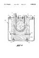
- FIG. 4is an elevation view, partially in cross-section, taken along line 4--4 of FIG. 3;
- FIG. 5is a pictorial view illustrating one embodiment of the present invention.
- FIG. 6is a pictorial view illustrating another embodiment of the present invention.
- FIG. 1shows a juice dispensing tower 10 designed to dispense juice from the dispensing valves 11 into a cup (not shown).
- Dispenser 10includes a housing 12 which defines a cup platform 14 and a platform grill 15 which allows liquid not captured in a cup to pass through the platform grill 15 and into a spill reservoir 16, shown in FIG. 3.
- Each of dispensing valves 11include a nozzle 21 which is secured to housing 12 by a nozzle bushing 22. Depression of a push button 23 by an operator activates nozzle 21 to direct a liquid product downwardly into a cup.
- the depression of the dispensing button 23activates a brix control valve 24 and a peristaltic pump 25 to draw fruit juice or vegetable juice concentrate to a concentrate static mixer portion 26 of valve 11 where it is mixed with water to form juice product and ultimately dispensed from the opening 27 of nozzle 21.
- brix control valve 24is actuated, the peristaltic pump 25 is actuated and chilled water is dispensed from the water conduits 31, via a water valve outlet opening 37, into static mixer portion 26 of each of dispensing valves 11. Therein, it is mixed with juice concentrate released from a juice conduit 32. The juice product formed is then dispensed from opening 27.
- brix dial 33is provided for adjustment behind a removable brix cover 34. As outlined, dispensing valves 11 are standard and will not be described in further detail.
- Each water conduit 31extends between the chilled water manifold 35 and one of the dispensing valves 11 as seen in FIG. 2.
- Chilled water manifold 35is coiled for maximum cooling effect within the chilled water reservoir 36.
- mechanical refrigeration meansi.e. evaporator tubing 41, is used to form the ice banks 42 which in turn cool a water bath within chilled water reservoir 36, thus adequately cooling supply water beginning at the water inlet coupling 43.
- chilled water reservoir 36is provided with the insulation 40 at at least the front face 13 of housing 12. Generally the entire chilled water compartment is insulated.
- Chilled water manifold 35 and the mechanical refrigeration meansare standard and will not be described in further detail.
- a pump housing 44Located below water manifold 35 is a pump housing 44.
- a removable front cover 45provides at least partial access to the system therein.
- Mounted thereinis peristaltic pump 25 on a support frame 46.
- a pump motor 47drives a pump shaft 51 through a gear box 52.
- the pump drive electronics 53actuate pump motor 47 when push button 23 is activated.
- each dispensing valve 11is connected to an individual peristaltic pump 25 with the accompanying pump drive electronics 53.
- a drain tube 54is also located within pump housing 44. Drain tube 54 leads from spill reservoir 16, through pump housing 44 and out through the back face 54 of pump housing 44 to a waste drain (not shown).
- a peristaltic pumpcomprises a rotor 61, rotatably driven by pump drive shaft 51, which is supported for rotation within a peristaltic housing 62.
- the support blocks 63a, 63b and 63care adapted to support an individual segment of a flexible tubing 65 which is placed in engagement with rotor 61, as shown in FIG. 4.
- Rotor 61having the curvilinear projections 67 on the outer circumference 68, causes peristaltic pumping through tubing 65 by pinching tubing 65 between one of the curvilinear projections 67 and support block 63b.
- the curvilinear portionsare often rollers.
- a concentrate suction conduit 71is connected to pump 25 at a coupling 72.
- Peristaltic pumpingcauses a vacuum or suction action within conduit 71 drawing concentrate.
- the pumping actionalso meters concentrate flow by collapsing tubing 65 between individual curvilinear projections 67 and feeds metered concentrate through outlet 73 into pump outlet tubing 74, which is in turn connected to concentrate valve inlet 75.
- support blocks 63a, 63b and 63care mounted within peristaltic housing 62 by cap screws 76, thus easing replacement of flexible tubing 65 when necessary.
- Peristaltic pump 25 and variations thereofare standard and well known in the art.
- dispensing tower 10 and the mechanics within housing 12comprise a first station 77 for the juice dispenser system 17.
- the juice concentrate reservoirlocated at a location remote from first station 77, comprises a second station 78.
- a concentrate suction tube 82Extending from a concentrate housing inlet fitting 81 is a concentrate suction tube 82. Concentrate suction tubing 82 is connected at a valve 83 to a bag-in-box juice concentrate reservoir 84. It will be appreciated that each of dispensing or mixing valves 11 is individually connected, through an individual peristaltic pump 25, to an individual bag-in-box concentrate reservoir 84, as best seen in FIG. 2.
- a bag-in-box concentrate reservoirconsists of a corrugated cardboard box having a plastic or foil liner which is fitted with a nipple. Valve 83 attaches to the nipple (not shown) at one end and suction tube 82 at the other end.
- Peristaltic pump 25is capable of drawing juice concentrate through suction tube 82 from bag-in-box concentrate reservoir 84 to a length generally around 50 feet, where dimension "A" in FIG. 5 is approximately 50 feet. It has been further found that juice dispensing system 17 can draw juice concentrate from bag-in-box concentrate reservoir 84 and develop 3 to 4 feet of head from 50 feet, where dimension "B" in FIG. 5 is generally equal to 3 feet. When suction tube 82 is somewhat less than 50 feet, a greater amount of head can be developed. For instance, as shown in FIG. 6, dimension "C" is equal to generally 25 feet.
- juice dispensing system 17is capable of developing approximately 15 feet of head.
- Dimension "D" in FIG. 6represents 15 feet of head.
- thisallows juice dispenser 10 to be located within a restaurant serving area 85 for use by restaurant employees or restaurant customers, while juice reservoir 84 is located in a back storage room 86 behind a wall 87 where space is not at a premium and where empty reservoirs 84 may be changed easily and quickly.
- juice reservoirs 84may be located in a basement storage room 87 below the floor level 88 of restaurant 85 since system 17 and peristaltic pump 25 are capable of developing at least 15 feet of head.
- the peristaltic action of the pump 25alone provides drawing power moving concentrate from the bag-in-box 84 to the dispensing tower 10.
- concentratewas forced into the peristaltic pump by gravity from a reservoir directly above the pump or by an upstream pump.
- a juice dispensermay be removed at the end of its useful life in one piece. There is no need to worry about additional pumps in back rooms. With the high turnover of supply contracts, restaurants change vendors very frequently. With the short-term contracts, there is a great need to simplify the installation and removal of dispensing equipment without sacrificing the advantages of remote dispensing units.
- the present inventionhas surprisingly found that a peristaltic pump is capable of both metering juice concentrate as well as developing vacuum or suction within suction tube 82 such that juice concentrate can be drawn through approximately 50 feet of tubing and additionally develop 3 to 4 feet of head.
- the present inventionprovides a remote juice dispensing system in which all components other than the disposable and inexpensive concentrate reservoirs are contained within a single dispensing appliance without sacrificing the advantages of a remote unit.
Landscapes
- Engineering & Computer Science (AREA)
- Mechanical Engineering (AREA)
- Physics & Mathematics (AREA)
- Thermal Sciences (AREA)
- Devices For Dispensing Beverages (AREA)
Abstract
Description
Claims (8)
Priority Applications (2)
| Application Number | Priority Date | Filing Date | Title |
|---|---|---|---|
| US08/695,619US5890626A (en) | 1996-08-12 | 1996-08-12 | Remote juice dispenser |
| US09/286,224US6170707B1 (en) | 1996-08-12 | 1999-04-05 | Remote juice dispenser |
Applications Claiming Priority (1)
| Application Number | Priority Date | Filing Date | Title |
|---|---|---|---|
| US08/695,619US5890626A (en) | 1996-08-12 | 1996-08-12 | Remote juice dispenser |
Related Child Applications (1)
| Application Number | Title | Priority Date | Filing Date |
|---|---|---|---|
| US09/286,224ContinuationUS6170707B1 (en) | 1996-08-12 | 1999-04-05 | Remote juice dispenser |
Publications (1)
| Publication Number | Publication Date |
|---|---|
| US5890626Atrue US5890626A (en) | 1999-04-06 |
Family
ID=24793766
Family Applications (2)
| Application Number | Title | Priority Date | Filing Date |
|---|---|---|---|
| US08/695,619Expired - LifetimeUS5890626A (en) | 1996-08-12 | 1996-08-12 | Remote juice dispenser |
| US09/286,224Expired - LifetimeUS6170707B1 (en) | 1996-08-12 | 1999-04-05 | Remote juice dispenser |
Family Applications After (1)
| Application Number | Title | Priority Date | Filing Date |
|---|---|---|---|
| US09/286,224Expired - LifetimeUS6170707B1 (en) | 1996-08-12 | 1999-04-05 | Remote juice dispenser |
Country Status (1)
| Country | Link |
|---|---|
| US (2) | US5890626A (en) |
Cited By (24)
| Publication number | Priority date | Publication date | Assignee | Title |
|---|---|---|---|---|
| US6170707B1 (en)* | 1996-08-12 | 2001-01-09 | Imi Cornelius Inc. | Remote juice dispenser |
| US6237810B1 (en)* | 2000-03-29 | 2001-05-29 | The Coca-Cola Company | Modular beverage dispenser |
| US6264069B1 (en)* | 1999-06-15 | 2001-07-24 | The Coca-Cola Company | Pulsation dampener for beverage dispensers and fountain equipment |
| US6375042B1 (en)* | 1997-08-06 | 2002-04-23 | Valpar Industrial Limited | Beverage distributing unit |
| US6708741B1 (en) | 2000-08-24 | 2004-03-23 | Ocean Spray Cranberries, Inc. | Beverage dispenser |
| US6726062B2 (en) | 2002-03-11 | 2004-04-27 | Bunn-O-Matic Corporation | System for producing beverages |
| US20070205221A1 (en)* | 2006-03-06 | 2007-09-06 | The Coca-Cola Company | Beverage Dispensing System |
| US20070205220A1 (en)* | 2006-03-06 | 2007-09-06 | The Coca-Cola Company | Juice Dispensing System |
| US20070212468A1 (en)* | 2006-03-06 | 2007-09-13 | The Coca-Cola Company | Methods and Apparatuses for Making Compositions Comprising an Acid and an Acid Degradable Component and/or Compositions Comprising a Plurality of Selectable Components |
| US20070267441A1 (en)* | 2006-03-06 | 2007-11-22 | The Coca-Cola Company | Dispenser for Beverages Including Juices |
| US20090069932A1 (en)* | 2007-09-06 | 2009-03-12 | The Coca-Cola Company | Method and Apparatuses for Providing a Selectable Beverage |
| US20090069933A1 (en)* | 2007-09-06 | 2009-03-12 | The Coca-Cola Company | Systems and methods of selecting and dispensing products |
| US20090302059A1 (en)* | 2005-03-21 | 2009-12-10 | Lancer Partnership Ltd. | Methods and apparatus for pumping and dispensing |
| US20100054975A1 (en)* | 2005-11-18 | 2010-03-04 | Araz Ibragimov | pulsatile peristaltic pump for use in a cardiopulmonary bypass |
| US20100237099A1 (en)* | 2006-03-06 | 2010-09-23 | The Coca-Cola Company | Beverage Dispensing System |
| US20100318225A1 (en)* | 2008-12-08 | 2010-12-16 | Enodis Corporation | Controller and method of controlling an integrated system for dispensing and blending/mixing beverage ingredients |
| US20120298693A1 (en)* | 2011-05-26 | 2012-11-29 | Pepsico, Inc. | Multi-Tower Modular Dispensing System |
| US8739840B2 (en) | 2010-04-26 | 2014-06-03 | The Coca-Cola Company | Method for managing orders and dispensing beverages |
| US8757222B2 (en) | 2010-04-26 | 2014-06-24 | The Coca-Cola Company | Vessel activated beverage dispenser |
| US9415992B2 (en) | 2006-03-06 | 2016-08-16 | The Coca-Cola Company | Dispenser for beverages having a rotary micro-ingredient combination chamber |
| US10280060B2 (en) | 2006-03-06 | 2019-05-07 | The Coca-Cola Company | Dispenser for beverages having an ingredient mixing module |
| CN110668384A (en)* | 2019-11-04 | 2020-01-10 | 比率机器人科技(北京)有限公司 | Material tower for automatic catering equipment and material transportation method thereof |
| CN110680189A (en)* | 2019-11-13 | 2020-01-14 | 比率机器人科技(北京)有限公司 | Automatic catering device and method thereof |
| US11247893B2 (en)* | 2015-07-29 | 2022-02-15 | The Coca-Cola Company | Modular system for dispensing additional ingredients |
Families Citing this family (9)
| Publication number | Priority date | Publication date | Assignee | Title |
|---|---|---|---|---|
| US7048147B2 (en)* | 2003-02-21 | 2006-05-23 | The Coca-Cola Company | Liquid dispensing device |
| US20090277199A1 (en)* | 2004-12-08 | 2009-11-12 | Teknoloji Dizayn Studyo Produksiyon Ve Reklamcilik Anonim Sirketi | Refrigerator capable of stock monitoring by providing ideal storage conditions |
| US8046976B2 (en)* | 2006-07-25 | 2011-11-01 | The Coca-Cola Company | Devices and methods for packaging beverages |
| US7997448B1 (en)* | 2007-02-01 | 2011-08-16 | Robert Leyva | Universal beverage dispenser |
| US8857666B2 (en)* | 2010-04-15 | 2014-10-14 | Edward L. O'Keefe, JR. | Wine dispensing system |
| US8640931B2 (en)* | 2011-02-01 | 2014-02-04 | Emerald Wine Systems, LLC | Tri-function tap for beverages |
| US8985396B2 (en)* | 2011-05-26 | 2015-03-24 | Pepsico. Inc. | Modular dispensing system |
| RU2725538C2 (en)* | 2015-01-30 | 2020-07-02 | Анхойзер-Буш Инбев С.А. | Methods, devices and systems for production of a beverage from the main liquid and ingredient |
| AU2016210828B2 (en) | 2015-01-30 | 2020-09-03 | Anheuser-Busch Inbev S.A. | Pressurized beverage concentrates and appliances and methods for producing beverages therefrom |
Citations (26)
| Publication number | Priority date | Publication date | Assignee | Title |
|---|---|---|---|---|
| US2880910A (en)* | 1956-07-09 | 1959-04-07 | Vendo Co | Empty indicating device and gas purging system for drink vending machines |
| US3528587A (en)* | 1968-06-25 | 1970-09-15 | Nedlog Co | Automatic liquid feed device |
| US3643835A (en)* | 1970-02-13 | 1972-02-22 | Nedlog Co | Automatic liquid proportioner |
| US3853244A (en)* | 1971-09-13 | 1974-12-10 | Reynolds Products | Remote drink dispenser |
| US3898861A (en)* | 1973-08-20 | 1975-08-12 | Cornelius Co | Beverage dispenser |
| US4042151A (en)* | 1976-05-13 | 1977-08-16 | Karma Division Of Brandt, Inc. | Beverage mixing and dispensing machine |
| US4189067A (en)* | 1977-02-14 | 1980-02-19 | Lykes Pasco Packing Company, Dispenser Division | Electronic control for dispenser system |
| US4228930A (en)* | 1977-09-09 | 1980-10-21 | Cole-Parmer Instrument Company | Dispensing pump |
| GB2098963A (en)* | 1981-05-25 | 1982-12-01 | Douwe Egberts Tabaksfab | Method and apparatus or metering beverage concentrates |
| US4478357A (en)* | 1983-03-03 | 1984-10-23 | Multiplex Company, Inc. | Citrus fruit juice dispensing apparatus |
| DE8512792U1 (en)* | 1985-05-02 | 1986-08-28 | Magnus GmbH, 5630 Remscheid | Device for cooling drinks |
| DE8512793U1 (en)* | 1985-05-02 | 1986-08-28 | Magnus GmbH, 5630 Remscheid | Drinks counter |
| US4610145A (en)* | 1984-09-21 | 1986-09-09 | Arzberger William A | Post mix fruit juice dispenser |
| US4645095A (en)* | 1984-03-19 | 1987-02-24 | Jet Spray Corp. | Syrup sensor for dispensing machine |
| US4717045A (en)* | 1984-03-19 | 1988-01-05 | Jet Spray Corp. | Syrup sensor for dispensing machine |
| US4728005A (en)* | 1984-03-19 | 1988-03-01 | Jet Spray Corp. | Self-fill system |
| US4781310A (en)* | 1986-12-19 | 1988-11-01 | The Coca-Cola Company | Beverage dispenser |
| US4860923A (en)* | 1986-10-29 | 1989-08-29 | The Coca-Cola Company | Postmix juice dispensing system |
| US5114045A (en)* | 1988-10-28 | 1992-05-19 | Bongrain S.A. | Method and an installation for conserving and/or dispensing a liquid or semi-liquid substance |
| US5114047A (en)* | 1990-08-14 | 1992-05-19 | Lykes Pasco Inc. | Pump and mixing device for liquids |
| US5190189A (en)* | 1990-10-30 | 1993-03-02 | Imi Cornelius Inc. | Low height beverage dispensing apparatus |
| US5249706A (en)* | 1988-09-22 | 1993-10-05 | John Szabo | Refrigerated liquid dispenser having a shut-off valve |
| US5257917A (en)* | 1992-10-02 | 1993-11-02 | Cole-Parmer Instrument Company | Peristaltic pump having means for reducing flow pulsation |
| US5279446A (en)* | 1991-01-11 | 1994-01-18 | The Cornelius Company | Beverage cooling system |
| US5537838A (en)* | 1994-11-02 | 1996-07-23 | Jet Spray Corp. | Beverage dispenser |
| US5564601A (en)* | 1994-12-05 | 1996-10-15 | Cleland; Robert K. | Beverage dispensing machine with improved liquid chiller |
Family Cites Families (1)
| Publication number | Priority date | Publication date | Assignee | Title |
|---|---|---|---|---|
| US5890626A (en)* | 1996-08-12 | 1999-04-06 | Imi Wilshire Inc. | Remote juice dispenser |
- 1996
- 1996-08-12USUS08/695,619patent/US5890626A/ennot_activeExpired - Lifetime
- 1999
- 1999-04-05USUS09/286,224patent/US6170707B1/ennot_activeExpired - Lifetime
Patent Citations (26)
| Publication number | Priority date | Publication date | Assignee | Title |
|---|---|---|---|---|
| US2880910A (en)* | 1956-07-09 | 1959-04-07 | Vendo Co | Empty indicating device and gas purging system for drink vending machines |
| US3528587A (en)* | 1968-06-25 | 1970-09-15 | Nedlog Co | Automatic liquid feed device |
| US3643835A (en)* | 1970-02-13 | 1972-02-22 | Nedlog Co | Automatic liquid proportioner |
| US3853244A (en)* | 1971-09-13 | 1974-12-10 | Reynolds Products | Remote drink dispenser |
| US3898861A (en)* | 1973-08-20 | 1975-08-12 | Cornelius Co | Beverage dispenser |
| US4042151A (en)* | 1976-05-13 | 1977-08-16 | Karma Division Of Brandt, Inc. | Beverage mixing and dispensing machine |
| US4189067A (en)* | 1977-02-14 | 1980-02-19 | Lykes Pasco Packing Company, Dispenser Division | Electronic control for dispenser system |
| US4228930A (en)* | 1977-09-09 | 1980-10-21 | Cole-Parmer Instrument Company | Dispensing pump |
| GB2098963A (en)* | 1981-05-25 | 1982-12-01 | Douwe Egberts Tabaksfab | Method and apparatus or metering beverage concentrates |
| US4478357A (en)* | 1983-03-03 | 1984-10-23 | Multiplex Company, Inc. | Citrus fruit juice dispensing apparatus |
| US4728005A (en)* | 1984-03-19 | 1988-03-01 | Jet Spray Corp. | Self-fill system |
| US4717045A (en)* | 1984-03-19 | 1988-01-05 | Jet Spray Corp. | Syrup sensor for dispensing machine |
| US4645095A (en)* | 1984-03-19 | 1987-02-24 | Jet Spray Corp. | Syrup sensor for dispensing machine |
| US4610145A (en)* | 1984-09-21 | 1986-09-09 | Arzberger William A | Post mix fruit juice dispenser |
| DE8512793U1 (en)* | 1985-05-02 | 1986-08-28 | Magnus GmbH, 5630 Remscheid | Drinks counter |
| DE8512792U1 (en)* | 1985-05-02 | 1986-08-28 | Magnus GmbH, 5630 Remscheid | Device for cooling drinks |
| US4860923A (en)* | 1986-10-29 | 1989-08-29 | The Coca-Cola Company | Postmix juice dispensing system |
| US4781310A (en)* | 1986-12-19 | 1988-11-01 | The Coca-Cola Company | Beverage dispenser |
| US5249706A (en)* | 1988-09-22 | 1993-10-05 | John Szabo | Refrigerated liquid dispenser having a shut-off valve |
| US5114045A (en)* | 1988-10-28 | 1992-05-19 | Bongrain S.A. | Method and an installation for conserving and/or dispensing a liquid or semi-liquid substance |
| US5114047A (en)* | 1990-08-14 | 1992-05-19 | Lykes Pasco Inc. | Pump and mixing device for liquids |
| US5190189A (en)* | 1990-10-30 | 1993-03-02 | Imi Cornelius Inc. | Low height beverage dispensing apparatus |
| US5279446A (en)* | 1991-01-11 | 1994-01-18 | The Cornelius Company | Beverage cooling system |
| US5257917A (en)* | 1992-10-02 | 1993-11-02 | Cole-Parmer Instrument Company | Peristaltic pump having means for reducing flow pulsation |
| US5537838A (en)* | 1994-11-02 | 1996-07-23 | Jet Spray Corp. | Beverage dispenser |
| US5564601A (en)* | 1994-12-05 | 1996-10-15 | Cleland; Robert K. | Beverage dispensing machine with improved liquid chiller |
Non-Patent Citations (2)
| Title |
|---|
| English translation of claims of G 8512792.2.* |
| English translation of claims of G 8512793.0.* |
Cited By (49)
| Publication number | Priority date | Publication date | Assignee | Title |
|---|---|---|---|---|
| US6170707B1 (en)* | 1996-08-12 | 2001-01-09 | Imi Cornelius Inc. | Remote juice dispenser |
| US6375042B1 (en)* | 1997-08-06 | 2002-04-23 | Valpar Industrial Limited | Beverage distributing unit |
| US6264069B1 (en)* | 1999-06-15 | 2001-07-24 | The Coca-Cola Company | Pulsation dampener for beverage dispensers and fountain equipment |
| US6237810B1 (en)* | 2000-03-29 | 2001-05-29 | The Coca-Cola Company | Modular beverage dispenser |
| US6708741B1 (en) | 2000-08-24 | 2004-03-23 | Ocean Spray Cranberries, Inc. | Beverage dispenser |
| US6726062B2 (en) | 2002-03-11 | 2004-04-27 | Bunn-O-Matic Corporation | System for producing beverages |
| US20090302059A1 (en)* | 2005-03-21 | 2009-12-10 | Lancer Partnership Ltd. | Methods and apparatus for pumping and dispensing |
| EP2341250A3 (en)* | 2005-03-21 | 2011-10-12 | Lancer Corporation | Dispenser with self closing dispensing valve and peristaltic pump |
| US8317499B2 (en)* | 2005-11-18 | 2012-11-27 | Araz Ibragimov | Pulsatile peristaltic pump for use in a cardiopulmonary bypass |
| US20100054975A1 (en)* | 2005-11-18 | 2010-03-04 | Araz Ibragimov | pulsatile peristaltic pump for use in a cardiopulmonary bypass |
| US10631558B2 (en) | 2006-03-06 | 2020-04-28 | The Coca-Cola Company | Methods and apparatuses for making compositions comprising an acid and an acid degradable component and/or compositions comprising a plurality of selectable components |
| US8807393B2 (en) | 2006-03-06 | 2014-08-19 | The Coca-Cola Company | Beverage dispensing system |
| US10029904B2 (en) | 2006-03-06 | 2018-07-24 | The Coca-Cola Company | Beverage dispensing system |
| US20070267441A1 (en)* | 2006-03-06 | 2007-11-22 | The Coca-Cola Company | Dispenser for Beverages Including Juices |
| US7757896B2 (en) | 2006-03-06 | 2010-07-20 | The Coca-Cola Company | Beverage dispensing system |
| US20100237099A1 (en)* | 2006-03-06 | 2010-09-23 | The Coca-Cola Company | Beverage Dispensing System |
| US9821992B2 (en) | 2006-03-06 | 2017-11-21 | The Coca-Cola Company | Juice dispensing system |
| US7913879B2 (en) | 2006-03-06 | 2011-03-29 | The Coca-Cola Company | Beverage dispensing system |
| US20110163126A1 (en)* | 2006-03-06 | 2011-07-07 | The Coca-Cola Company | Beverage Dispensing System |
| US20070212468A1 (en)* | 2006-03-06 | 2007-09-13 | The Coca-Cola Company | Methods and Apparatuses for Making Compositions Comprising an Acid and an Acid Degradable Component and/or Compositions Comprising a Plurality of Selectable Components |
| US8162181B2 (en) | 2006-03-06 | 2012-04-24 | The Coca-Cola Company | Beverage dispensing system |
| US10280060B2 (en) | 2006-03-06 | 2019-05-07 | The Coca-Cola Company | Dispenser for beverages having an ingredient mixing module |
| US9415992B2 (en) | 2006-03-06 | 2016-08-16 | The Coca-Cola Company | Dispenser for beverages having a rotary micro-ingredient combination chamber |
| US20070205220A1 (en)* | 2006-03-06 | 2007-09-06 | The Coca-Cola Company | Juice Dispensing System |
| US20070205221A1 (en)* | 2006-03-06 | 2007-09-06 | The Coca-Cola Company | Beverage Dispensing System |
| US10631560B2 (en) | 2006-03-06 | 2020-04-28 | The Coca-Cola Company | Methods and apparatuses for making compositions comprising an acid and an acid degradable component and/or compositions comprising a plurality of selectable components |
| US8453879B2 (en) | 2006-03-06 | 2013-06-04 | The Coca-Cola Company | Beverage dispensing system |
| US8960500B2 (en) | 2006-03-06 | 2015-02-24 | The Coca-Cola Company | Dispenser for beverages including juices |
| US8251258B2 (en) | 2007-09-06 | 2012-08-28 | The Coca-Cola Company | Systems and methods of selecting and dispensing products |
| US10046959B2 (en) | 2007-09-06 | 2018-08-14 | The Coca-Cola Company | Method and apparatuses for providing a selectable beverage |
| US20090069933A1 (en)* | 2007-09-06 | 2009-03-12 | The Coca-Cola Company | Systems and methods of selecting and dispensing products |
| US8814000B2 (en) | 2007-09-06 | 2014-08-26 | The Coca-Cola Company | Method and apparatuses for providing a selectable beverage |
| US8851329B2 (en) | 2007-09-06 | 2014-10-07 | The Coca-Cola Company | Systems and methods of selecting and dispensing products |
| US8434642B2 (en) | 2007-09-06 | 2013-05-07 | The Coca-Cola Company | Method and apparatus for providing a selectable beverage |
| US8162176B2 (en) | 2007-09-06 | 2012-04-24 | The Coca-Cola Company | Method and apparatuses for providing a selectable beverage |
| US20090069932A1 (en)* | 2007-09-06 | 2009-03-12 | The Coca-Cola Company | Method and Apparatuses for Providing a Selectable Beverage |
| US8606396B2 (en)* | 2008-12-08 | 2013-12-10 | Enodis Corporation | Controller and method of controlling an integrated system for dispensing and blending/mixing beverage ingredients |
| US8721162B2 (en) | 2008-12-08 | 2014-05-13 | Enodis Corporation | Controller and method of controlling an integrated system for dispensing and blending/mixing beverage ingredients |
| US20100318225A1 (en)* | 2008-12-08 | 2010-12-16 | Enodis Corporation | Controller and method of controlling an integrated system for dispensing and blending/mixing beverage ingredients |
| US8739840B2 (en) | 2010-04-26 | 2014-06-03 | The Coca-Cola Company | Method for managing orders and dispensing beverages |
| US8757222B2 (en) | 2010-04-26 | 2014-06-24 | The Coca-Cola Company | Vessel activated beverage dispenser |
| US20120298693A1 (en)* | 2011-05-26 | 2012-11-29 | Pepsico, Inc. | Multi-Tower Modular Dispensing System |
| US10227226B2 (en) | 2011-05-26 | 2019-03-12 | Pepsico, Inc. | Multi-tower modular dispensing system |
| US9764935B2 (en) | 2011-05-26 | 2017-09-19 | Pepsico, Inc. | Multi-tower modular dispensing system |
| US9193575B2 (en) | 2011-05-26 | 2015-11-24 | Pepsico, Inc. | Multi-tower modular dispensing system |
| US8746506B2 (en)* | 2011-05-26 | 2014-06-10 | Pepsico, Inc. | Multi-tower modular dispensing system |
| US11247893B2 (en)* | 2015-07-29 | 2022-02-15 | The Coca-Cola Company | Modular system for dispensing additional ingredients |
| CN110668384A (en)* | 2019-11-04 | 2020-01-10 | 比率机器人科技(北京)有限公司 | Material tower for automatic catering equipment and material transportation method thereof |
| CN110680189A (en)* | 2019-11-13 | 2020-01-14 | 比率机器人科技(北京)有限公司 | Automatic catering device and method thereof |
Also Published As
| Publication number | Publication date |
|---|---|
| US6170707B1 (en) | 2001-01-09 |
Similar Documents
| Publication | Publication Date | Title |
|---|---|---|
| US5890626A (en) | Remote juice dispenser | |
| US5353963A (en) | Post mix dispenser | |
| CA1275984C (en) | Beverage dispenser | |
| US7997448B1 (en) | Universal beverage dispenser | |
| US5725125A (en) | Method of and means for providing multiple flavored beverages from a dispensing valve from a beverage dispensing unit | |
| US9643828B2 (en) | Arcuate multi-dispensing beverage dispenser | |
| US10626003B2 (en) | Post-mix drink dispensing system with independently controlled syrup pumps | |
| CA1331169C (en) | Postmix juice dispensing system | |
| US7419073B2 (en) | Refrigerator having a fluid director access door | |
| US7278552B2 (en) | Water supplier for a beverage dispensing apparatus of a refrigerator | |
| US7337924B2 (en) | Refrigerator which removably holds a drink supply container having a valve co-acting with an engager | |
| US5537838A (en) | Beverage dispenser | |
| US8973786B2 (en) | Beverage dispenser with on-demand refrigeration | |
| US20070157656A1 (en) | Chilled beverage delivery system | |
| US20130277394A1 (en) | Moveable roll around self-contained ice cooled beverage dispensing apparatus | |
| US5160461A (en) | Chilled beverage system | |
| JP4309128B2 (en) | 3-barrel frozen product distributor | |
| US5192003A (en) | Beverage bar structure and system | |
| JPH1146983A (en) | Beverage supply machine and method for supplying beverage | |
| CN108135389B (en) | Modular micro-metering dispensing system | |
| US5395013A (en) | Beverage delivery apparatus provided with a pump-containing ice chest | |
| US20040016772A1 (en) | Flavor dispensing device | |
| WO2025201634A1 (en) | A beverage dispensing apparatus | |
| HK1255618B (en) | Modular micro dosing dispensing system | |
| HK1127519B (en) | Beverage dispenser with on-demand refrigeration |
Legal Events
| Date | Code | Title | Description |
|---|---|---|---|
| AS | Assignment | Owner name:WILSHIRE PARTNERS, OHIO Free format text:ASSIGNMENT OF ASSIGNORS INTEREST;ASSIGNORS:WOLSKI, PETER F.;LONG, MICHAEL S.;SEGIET, WILLIAM W., JR.;REEL/FRAME:008161/0718 Effective date:19960807 | |
| AS | Assignment | Owner name:IMI WILSHIRE INC., MINNESOTA Free format text:ASSIGNMENT OF ASSIGNORS INTEREST;ASSIGNOR:WILSHIRE PARTNERS;REEL/FRAME:008412/0088 Effective date:19970314 | |
| STCF | Information on status: patent grant | Free format text:PATENTED CASE | |
| AS | Assignment | Owner name:IMI CORNELIUS INC., MINNESOTA Free format text:ASSIGNMENT OF ASSIGNORS INTEREST;ASSIGNOR:IMI WILSHIRE INC.;REEL/FRAME:011177/0043 Effective date:20000630 | |
| FPAY | Fee payment | Year of fee payment:4 | |
| FEPP | Fee payment procedure | Free format text:PAT HOLDER NO LONGER CLAIMS SMALL ENTITY STATUS, ENTITY STATUS SET TO UNDISCOUNTED (ORIGINAL EVENT CODE: STOL); ENTITY STATUS OF PATENT OWNER: LARGE ENTITY | |
| FEPP | Fee payment procedure | Free format text:ENTITY STATUS SET TO UNDISCOUNTED (ORIGINAL EVENT CODE: BIG.); ENTITY STATUS OF PATENT OWNER: LARGE ENTITY | |
| FPAY | Fee payment | Year of fee payment:8 | |
| FPAY | Fee payment | Year of fee payment:12 | |
| AS | Assignment | Owner name:CORNELIUS, INC., MINNESOTA Free format text:ARTICLES OF INCORPORATION;ASSIGNOR:IMI CORNELIUS, INC.;REEL/FRAME:033050/0172 Effective date:20140128 | |
| FEPP | Fee payment procedure | Free format text:PAYOR NUMBER ASSIGNED (ORIGINAL EVENT CODE: ASPN); ENTITY STATUS OF PATENT OWNER: LARGE ENTITY |