US5890476A - Fuel delivery nozzle - Google Patents
Fuel delivery nozzleDownload PDFInfo
- Publication number
- US5890476A US5890476AUS08/908,338US90833897AUS5890476AUS 5890476 AUS5890476 AUS 5890476AUS 90833897 AUS90833897 AUS 90833897AUS 5890476 AUS5890476 AUS 5890476A
- Authority
- US
- United States
- Prior art keywords
- nozzle
- nitrous oxide
- fuel
- tip
- conduit
- Prior art date
- Legal status (The legal status is an assumption and is not a legal conclusion. Google has not performed a legal analysis and makes no representation as to the accuracy of the status listed.)
- Expired - Lifetime
Links
Images

Classifications
- F—MECHANICAL ENGINEERING; LIGHTING; HEATING; WEAPONS; BLASTING
- F02—COMBUSTION ENGINES; HOT-GAS OR COMBUSTION-PRODUCT ENGINE PLANTS
- F02M—SUPPLYING COMBUSTION ENGINES IN GENERAL WITH COMBUSTIBLE MIXTURES OR CONSTITUENTS THEREOF
- F02M67/00—Apparatus in which fuel-injection is effected by means of high-pressure gas, the gas carrying the fuel into working cylinders of the engine, e.g. air-injection type
- F02M67/10—Injectors peculiar thereto, e.g. valve less type
- F—MECHANICAL ENGINEERING; LIGHTING; HEATING; WEAPONS; BLASTING
- F02—COMBUSTION ENGINES; HOT-GAS OR COMBUSTION-PRODUCT ENGINE PLANTS
- F02M—SUPPLYING COMBUSTION ENGINES IN GENERAL WITH COMBUSTIBLE MIXTURES OR CONSTITUENTS THEREOF
- F02M25/00—Engine-pertinent apparatus for adding non-fuel substances or small quantities of secondary fuel to combustion-air, main fuel or fuel-air mixture
- F02M25/10—Engine-pertinent apparatus for adding non-fuel substances or small quantities of secondary fuel to combustion-air, main fuel or fuel-air mixture adding acetylene, non-waterborne hydrogen, non-airborne oxygen, or ozone
- F—MECHANICAL ENGINEERING; LIGHTING; HEATING; WEAPONS; BLASTING
- F02—COMBUSTION ENGINES; HOT-GAS OR COMBUSTION-PRODUCT ENGINE PLANTS
- F02M—SUPPLYING COMBUSTION ENGINES IN GENERAL WITH COMBUSTIBLE MIXTURES OR CONSTITUENTS THEREOF
- F02M69/00—Low-pressure fuel-injection apparatus ; Apparatus with both continuous and intermittent injection; Apparatus injecting different types of fuel
- F02M69/08—Low-pressure fuel-injection apparatus ; Apparatus with both continuous and intermittent injection; Apparatus injecting different types of fuel characterised by the fuel being carried by compressed air into main stream of combustion-air
- Y—GENERAL TAGGING OF NEW TECHNOLOGICAL DEVELOPMENTS; GENERAL TAGGING OF CROSS-SECTIONAL TECHNOLOGIES SPANNING OVER SEVERAL SECTIONS OF THE IPC; TECHNICAL SUBJECTS COVERED BY FORMER USPC CROSS-REFERENCE ART COLLECTIONS [XRACs] AND DIGESTS
- Y02—TECHNOLOGIES OR APPLICATIONS FOR MITIGATION OR ADAPTATION AGAINST CLIMATE CHANGE
- Y02T—CLIMATE CHANGE MITIGATION TECHNOLOGIES RELATED TO TRANSPORTATION
- Y02T10/00—Road transport of goods or passengers
- Y02T10/10—Internal combustion engine [ICE] based vehicles
- Y02T10/12—Improving ICE efficiencies
Definitions
- This inventionrelates generally to a fuel and nitrous oxide supply nozzle for a high performance internal combustion engine.
- turbo-chargers and blowersto increase the inlet pressure of the fuel/air mixture delivered to the combustion cylinders, or by injecting nitrous oxide into the inlet manifold so as to increase the amount of oxygen delivered to the combustion cylinders.
- Both turbos and blowersinduce a mixture of fuel and atmospheric air to move at higher pressure to the cylinders.
- the least costly of these three proceduresis the use of nitrous oxide injection.
- a typical nitrous oxide systeminduces both fuel and oxygen-rich nitrous oxide into the engine at a desired ratio to produce increased power without damage to any of the components of the engine.
- the nitrous oxideis injected with the fuel into the inlet manifold in order to supply the oxygen that is required to complete the combustion of the fuel in the combustion cylinders.
- this ratiois not balanced correctly, two things can result. First, if the mixture of nitrous oxide and fuel is too rich (too much fuel compared to the nitrous oxide), complete combustion will not occur of the fuel and optimal power of the engine will not be produced. Second, if the mixture is too lean (too little fuel compared to the nitrous oxide), the combustion will produce too much heat and there is a likelihood of damage to the engine.
- the ratio of the fuel to the nitrous oxideis controlled by limiting the size of the orifice in the supply lines of both the fuel and the nitrous oxide leading to the injection nozzle, and by controlling the pressure of both the fuel and the nitrous oxide delivered to the injection nozzle.
- nitrous oxideusually is supplied at a high pressure, up to 1,000 psig in a liquid state.
- the pressure of the nitrous oxidereduces radically from very high pressure to below atmospheric pressure, and the nitrous oxide changes state from liquid to gas. This results in a radical absorption of heat, and the nozzle structure tends to assume a temperature lower than the level of freezing for water, and the moisture carried in the stream of air past the nozzle tends to condense and freeze on the nozzle.
- nitrous oxidein its liquid state, preferably at a substantially constant temperature, as the nitrous oxide flows through the nozzle and into the air inlet manifold, with the nitrous oxide being permitted to change from its liquid state to its gaseous state as it emerges from the nozzle opening and moves into the stream of air flowing through the manifold. This tends to cause the nitrous oxide to change state as and after it emerges from the nozzle and as it enters the air stream.
- the fuelsuch as gasoline
- a zone of low pressure about the nozzle tip, where the nitrous oxide emerges from the nozzleso as to tend to draw the nitrous oxide into the zone of low pressure and away from the nozzle as the nitrous oxide emerges from the nozzle and changes from liquid to gas.
- Thistends to displace the effects of the radical change of temperature of the nitrous oxide, so that it is displaced from the nozzle and has less tendency to reduce the temperature of the nozzle itself, resulting in less likelihood of frost accumulating on the nozzle and of the flow from the nozzle becoming blocked.
- the low pressure at the nozzle tiptends to help atomize the fuel injected into the zone of low pressure.
- the present inventioncomprises an injection nozzle for mounting to a manifold of an internal combustion engine, for supplying fuel and nitrous oxide to the combustion chamber of the internal combustion engine.
- the nozzleincludes a nozzle tip that protrudes into the air stream of the manifold, and the nozzle tip is shaped in the form of a substantially symmetrical double-sided wing having a leading edge for facing the air stream in the manifold, and arcuate walls diverging rearwardly or down stream from the leading edge, and forming behind the leading edge of the wing a low pressure fuel delivery zone.
- the nitrous oxide and fuelare delivered to the fuel delivery zone behind the wing shaped tip of the nozzle.
- the dimensions of the conduits leading to the nozzle tip for both the nitrous oxide and the fuelare dimensioned so that the nitrous oxide and fuel will be delivered to the nozzle tip in liquid state.
- the stream of air flowing about the wing-shaped nozzle tiptends to form a zone of low pressure in the fuel delivery zone which is behind the leading edge of the nozzle tip. It is believed that the zone of low pressure tends to draw the nitrous oxide and gasoline out of the nozzle as the nitrous oxide changes state from liquid to gas, tending to displace the location where the nitrous oxide changes state and experiences a radical drop in temperature.
- the internal conduit of the nozzle through which the nitrous oxide flowsis rectilinear and of constant cross sectional area. This configuration of the nitrous oxide conduit assures that there will be no significant pressure drop in the nitrous oxide as it flows through the conduit, assuring that the nitrous oxide remains in its liquid state until it reaches the end of the constant dimension conduit. At its delivery end the nitrous oxide conduit is enlarged and turned toward the direction of flow of the air moving through the manifold and about the nozzle tip.
- the conduit that delivers the gasoline through the nozzleopens directly toward the path of the nitrous oxide as the nitrous oxide emerges from the delivery end of its conduit, so that the fluids moving together from the separate conduits become mixed and turbulent in a low pressure zone and the atomization of the fuel is enhanced by the low pressure and the turbulence and by the changing of the nitrous oxide from a liquid to a gas.
- the injection of the gasoline into the low pressure of the fuel delivery zone and the changing of the phase of the nitrous oxide in the same zonetends to atomize the gasoline into smaller particles, which later enhances the combustion of the fuel in the combustion chambers of the engine.
- Another object of this inventionis to provide an injection nozzle for the manifold of an internal combustion engine which includes a nozzle tip for projecting into the air stream of the manifold, with the nozzle tip being shaped in the form of a substantially synunetrical double-sided wing having a leading edge for facing the air stream and which forms a fuel delivery zone down stream of the leading edge which is maintained in a state of low pressure as the nitrous oxide and fuel are delivered to the fuel delivery zone, so as to draw the nitrous oxide from the nozzle and to displace the zone where the nitrous oxide changes state from liquid to gas and experiences a radical temperature drop.
- Another object of this inventionis to provide an improved injection nozzle for a high performance internal combustion engine which delivers and mixes nitrous oxide and gasoline in a zone of low pressure formed by the nozzle in the air stream of the manifold, for enhancing the mixing of the gases.
- Another object of the inventionis to provide a zone of low pressure adjacent a fuel injection nozzle where the fuel is delivered by the nozzle so that fuel moves into the low pressure zone and its atomization is enhanced by the low pressure.
- Another object of the inventionis to provide an improved injection nozzle for a high performance internal combustion engine for injecting fuel and nitrous oxide to the air stream moving to the engine, which forms a zone outside the nozzle and in the air stream in which the nitrous oxide changes from liquid to gas and the fuel is directed to the same zone so that the change of state of the nitrous oxide enhances the atomization of the fuel.
- FIG. 1is a bottom view of the fuel injection nozzle.
- FIG. 2is a side view thereof.
- FIG. 3is a side cross-sectional view thereof, showing the jet fittings displaced from the nozzle body.
- FIG. 4is a front view thereof.
- FIG. 5is a cross-sectional view taken along lines 5--5 of FIG. 3.
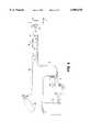
- FIG. 6is a schematic illustration of the fuel supply arrangement for supplying both gasoline and nitrous oxide to the nozzle of FIGS. 1-5.
- FIG. 1illustrates the fuel injection nozzle 10 which is an elongated nozzle body 12 sized and shaped for mounting to the side wall 14 of an air intake manifold of an internal combustion engine.
- the nozzle body 12includes a nozzle tip 16 which protrudes into the manifold 14, a nozzle base 15 which extends outwardly from the manifold, and an externally threaded intermediate body portion 20 that is sized and shaped to be threaded into the internally threaded bore 22 of the manifold 14, and supporting the nozzle body in its operative position.
- a pair of substantially parallel internal conduits 22 and 24extend from the nozzle base 18 to the nozzle tip 16.
- the first conduit 22is to be used for the supply of liquid nitrous oxide
- the second conduit 24is to be used for the supply of gasoline or other combustible fuel.
- the conduits 22 and 24are each of substantially constant cross-sectional area from base to tip, so as to reduce the tendency of the fluids to change pressure as the fluids flow through the conduits.
- the conduit 22 which delivers the nitrous oxideis 0.053 inches diameter.
- Threaded counterbores 26 and 28are formed in the nozzle base 18, and intersect the internal conduits 22 and 24, respectively. Jet fittings 30 and 32 are rotatably threaded into the counterbores 26 and 28. Each jet fitting includes an internal passage 34 and an exit port 36 which is of a predetermined cross-sectional area so as to permit a predetermined flow of fluid. The fittings 30 and 32 can be exchanged with other fittings having different sized jet ports 36 as might be desired.
- the externally threaded intermediate body portion 20 of the nozzle body 12is substantially cylindrical.
- the nozzle base 18is flared outwardly so as to provide an enlarged area for accommodating the internal counterbores 26 and 28.
- the nozzle tip 16is formed in the shape of a substantially symmetrical double-sided wing. As shown in FIG. 5, the nozzle tip includes a leading edge 40 that is arranged to face the oncoming air stream 42 that moves through the manifold 14.
- a cord line 44intersects the leading edge 40 of the nozzle tip, and arcuate walls 46 and 48 diverge symmetrically from the leading edge 40 away from the cord line 44, on opposite sides of the cord line.
- the nozzle tip 16is undercut to form an overhang or nose 50.
- the first internal conduit 22 which delivers the nitrous oxideextends into the nose 50 of the nozzle tip, and the conduit turns in the direction of air flow 42, so as to form an enlarged exit port 52 that faces in the direction of air flow 42, at an approximate right angle with respect to the length of the internal conduit 22.
- internal conduit 24 which transports the gasoline through the nozzleemerges from the conduit 24 to a U-shaped recess 54.
- the recessis open on two sides, one side facing the exit port 52 of first conduit 22, and the other side facing away from the leading edge 40 of the tip.
- nitrous oxideis present under pressure, typically at 1,000 psig, in a cylinder 58.
- the nitrous oxideis supplied through supply line 59 to solenoid 60, through delivery line 62 to the jet fitting 30 of the nozzle body 12.
- gasolineis delivered from a fuel cell 64 through fuel supply line 66, through filter 68 to fuel pump 70.
- the fuel pumpthen moves the fuel through line 72, through pressure regulator 74, through line 76, to solenoid 78.
- the fuelthen passes through delivery line 80 to the jet fitting 32, to the nozzle body 12.
- the passageis constricted by the smaller exit port 36 which is selected so as to provide the proper flow through the nozzle body 12.
- the nitrous oxidein a liquid state, moves through the port 36, through the substantially rectilinear internal conduit 22 until it reaches the nozzle tip 16, where the internal conduit 22 turns so as to form the larger exit port 52 in the nose 50 of the nozzle tip, so as to expel the nitrous oxide in a direction as generally indicated by arrow 84.
- the nitrous oxidepasses through the enlarged exit port 52, it beings its change of phase from liquid to gas.
- the fuelpasses through its constriction of jet fitting 32 and moves through the second internal conduit 24 until it emerges from the conduit into the U-shaped open recess 54.
- the fuelis thus propelled in the direction as generally indicated by arrow 86, so that the streams of fuel and nitrous oxide impinge one another.
- the nitrous oxidehaving been at a pressure of up to 1,000 psig as it moves in a liquid state through the first internal conduit of the nozzle body experiences a radical reduction in pressure as it emerges from the internal conduit 22 into the exit port 52 and moves on beyond the exit port 52.
- This radical reduction in pressureresults in a change of state of the nitrous oxide from a liquid to gas, and also results in a radical drop in temperature of the nitrous oxide.
- the flow of air 42 around the nose of the substantially symmetrical double-sided wing of the nozzle tip 16helps to generate a zone of low pressure in the vicinity of the exit port 52 and beyond the exit port in the direction of movement of the air flow 42 and in the U-shaped recess 54 which is located at the end of the gasoline internal conduit 24.
- This zone of reduced pressure and the change of phase of the nitrous oxideis believed to induce the mixing of the nitrous oxide gas and fuel, and enhance the atomization of the gasoline in the flow of nitrous oxide and atmospheric air which is moving from the nozzle body 12 toward the internal combustion engine 88, and it is believed that this aids in drawing the nitrous oxide away from the nozzle body so as to reduce the loss of heat from the nozzle body.
- the advantages of the nozzleresult primarily from the shape of its tip structure. Since the tip has a "winged" shape, the nozzle tip provides less obstruction to the flow of air through the inlet manifold. Therefore, there is less pressure drop in the inlet manifold due to an obstruction by the nozzle in the stream air and therefore more air reaches the combustion chambers of the engine and improves the power making capabilities of the engine and its components.
- Another advantage of using the winged shape structure of the inventionis the condition of the flow of fluids immediately beyond the nozzle, after the air has passed about the nozzle and forms a zone of low pressure at and beyond the tip of the nozzle.
- the zone of low pressure, the changing of phase of the nitrous oxide in the zone and the turbulence in the zoneprovides improved atomization of the fuel in the nitrous oxide stream, so that the fuel becomes better atomized and mixed with the oxygen, and the gases moving to the combustion chambers of the engine have better dispersion of the fuel.
- Another advantage of the improved nozzleis believed to be the tendency to displace the zone where the temperature drop occurs as caused by the change of state of the nitrous oxide further from the source of the nitrous oxide, so that the tendency of frost and ice forming on the nose of the nozzle tip is reduced. This tends to avoid a change of the pattern of gas flow from the nozzle.
Landscapes
- Engineering & Computer Science (AREA)
- Chemical & Material Sciences (AREA)
- Combustion & Propulsion (AREA)
- Mechanical Engineering (AREA)
- General Engineering & Computer Science (AREA)
- Fuel-Injection Apparatus (AREA)
Abstract
Description
Claims (6)
Priority Applications (1)
| Application Number | Priority Date | Filing Date | Title |
|---|---|---|---|
| US08/908,338US5890476A (en) | 1996-08-07 | 1997-08-07 | Fuel delivery nozzle |
Applications Claiming Priority (2)
| Application Number | Priority Date | Filing Date | Title |
|---|---|---|---|
| US2354996P | 1996-08-07 | 1996-08-07 | |
| US08/908,338US5890476A (en) | 1996-08-07 | 1997-08-07 | Fuel delivery nozzle |
Publications (1)
| Publication Number | Publication Date |
|---|---|
| US5890476Atrue US5890476A (en) | 1999-04-06 |
Family
ID=26697307
Family Applications (1)
| Application Number | Title | Priority Date | Filing Date |
|---|---|---|---|
| US08/908,338Expired - LifetimeUS5890476A (en) | 1996-08-07 | 1997-08-07 | Fuel delivery nozzle |
Country Status (1)
| Country | Link |
|---|---|
| US (1) | US5890476A (en) |
Cited By (20)
| Publication number | Priority date | Publication date | Assignee | Title |
|---|---|---|---|---|
| US6260546B1 (en)* | 1999-04-21 | 2001-07-17 | E. Lanny Vaughn | Direct nitrous injection system operable from zero to 100% throttle control |
| US6279557B1 (en) | 1999-08-20 | 2001-08-28 | Specialty Motorsports, Inc. | Spray bar pair assembly |
| US6453894B1 (en) | 1999-11-29 | 2002-09-24 | James J. Fischer | Power ring adapter assembly |
| US6520165B1 (en) | 2001-10-23 | 2003-02-18 | Michael Wayne Steele | Nozzle for emitting nitrous oxide for fuel to engines |
| US20040025832A1 (en)* | 2001-09-28 | 2004-02-12 | Oswald Baasch | Fuel injector nozzle adapter |
| US20040173695A1 (en)* | 2002-12-17 | 2004-09-09 | Patrick Matthew R. | Nitrous fuel nozzle and method of use |
| WO2004042221A3 (en)* | 2002-11-04 | 2004-09-23 | Holley Performance Products | Fuel injector nozzle adapter |
| US20050006499A1 (en)* | 1997-11-20 | 2005-01-13 | Thermos Michael J. | Nozzle |
| US20050081827A1 (en)* | 2003-10-17 | 2005-04-21 | Grant Barry S. | Nitrous oxide/fuel injector for air intake to internal combustion engine |
| US20070017492A1 (en)* | 2005-07-22 | 2007-01-25 | Oswald Baasch | Intake manifold plate adapter |
| WO2008010037A3 (en)* | 2006-07-12 | 2008-03-20 | Toyota Motor Co Ltd | Fuel injection device |
| US20090031700A1 (en)* | 2006-11-13 | 2009-02-05 | Space Propulsion Group, Inc. | Mixtures of oxides of nitrogen and oxygen as oxidizers for propulsion, gas generation and power generation applications |
| US20090280448A1 (en)* | 2008-05-12 | 2009-11-12 | Coprecitec, S.L. | Multiple gas pilot burner |
| US20130112171A1 (en)* | 2011-05-03 | 2013-05-09 | Go Natural Cng,Llc | Fuel injection adapters and related systems and methods |
| US10012197B2 (en) | 2013-10-18 | 2018-07-03 | Holley Performance Products, Inc. | Fuel injection throttle body |
| US10029561B2 (en) | 2014-11-07 | 2018-07-24 | Holley Performance Products, Inc. | Liquid reservoir system and method |
| US10391860B2 (en) | 2015-12-14 | 2019-08-27 | Holley Performance Products, Inc. | Systems and methods for installing and sealing fuel pump in fuel tank |
| KR20200118215A (en) | 2018-03-02 | 2020-10-14 | 타나카 세이미츠 코교 가부시키가이샤 | Adhesive application device and adhesive application method |
| US10961968B2 (en) | 2016-01-13 | 2021-03-30 | Fuel Injection Technology Inc. | EFI throttle body with side fuel injectors |
| US12421907B2 (en) | 2023-07-15 | 2025-09-23 | Holley Performance Products, Inc. | Electronic fuel injection throttle body assembly |
Citations (13)
| Publication number | Priority date | Publication date | Assignee | Title |
|---|---|---|---|---|
| US2551114A (en)* | 1948-03-24 | 1951-05-01 | Daniel And Florence Guggenheim | Two-liquid feeding device for combustion chambers |
| US2912064A (en)* | 1956-01-13 | 1959-11-10 | C A Norgren Company | Methods and apparatus for reclassifying aerosols |
| US3416730A (en)* | 1963-06-05 | 1968-12-17 | Charles C. Perry | Apparatus for providing multiple liquid jets |
| US3747859A (en)* | 1970-09-19 | 1973-07-24 | Messer Griesheim Gmbh | Torch for thermochemical processing of work pieces |
| US4270508A (en)* | 1979-10-12 | 1981-06-02 | U.S.A. 161 Developments Ltd. | Combustion control system |
| US4798190A (en)* | 1986-05-30 | 1989-01-17 | Nitrous Oxide Systems, Inc. | Nozzle |
| US4827888A (en)* | 1986-05-30 | 1989-05-09 | Nitrous Oxide Systems, Inc. | Nozzle |
| US5072883A (en)* | 1990-04-03 | 1991-12-17 | Spraying Systems Co. | Full cone spray nozzle with external air atomization |
| US5269275A (en)* | 1992-11-02 | 1993-12-14 | David Rook | Pulse width modulated controller for nitrous oxide and fuel delivery |
| US5449120A (en)* | 1991-06-11 | 1995-09-12 | Nippondenso Co., Ltd. | Fuel feed apparatus of internal combustion engine |
| US5456415A (en)* | 1994-04-07 | 1995-10-10 | Gardner; James J. | Atomizing nozzle for liquids |
| US5595163A (en)* | 1995-06-06 | 1997-01-21 | Hitachi America, Ltd. | Apparatus and method for controlling the fuel supply of a gas-fueled engine |
| US5699776A (en)* | 1997-03-06 | 1997-12-23 | Nitrous Express, Inc. | Nozzle for mixing oxidizer with fuel |
- 1997
- 1997-08-07USUS08/908,338patent/US5890476A/ennot_activeExpired - Lifetime
Patent Citations (13)
| Publication number | Priority date | Publication date | Assignee | Title |
|---|---|---|---|---|
| US2551114A (en)* | 1948-03-24 | 1951-05-01 | Daniel And Florence Guggenheim | Two-liquid feeding device for combustion chambers |
| US2912064A (en)* | 1956-01-13 | 1959-11-10 | C A Norgren Company | Methods and apparatus for reclassifying aerosols |
| US3416730A (en)* | 1963-06-05 | 1968-12-17 | Charles C. Perry | Apparatus for providing multiple liquid jets |
| US3747859A (en)* | 1970-09-19 | 1973-07-24 | Messer Griesheim Gmbh | Torch for thermochemical processing of work pieces |
| US4270508A (en)* | 1979-10-12 | 1981-06-02 | U.S.A. 161 Developments Ltd. | Combustion control system |
| US4827888A (en)* | 1986-05-30 | 1989-05-09 | Nitrous Oxide Systems, Inc. | Nozzle |
| US4798190A (en)* | 1986-05-30 | 1989-01-17 | Nitrous Oxide Systems, Inc. | Nozzle |
| US5072883A (en)* | 1990-04-03 | 1991-12-17 | Spraying Systems Co. | Full cone spray nozzle with external air atomization |
| US5449120A (en)* | 1991-06-11 | 1995-09-12 | Nippondenso Co., Ltd. | Fuel feed apparatus of internal combustion engine |
| US5269275A (en)* | 1992-11-02 | 1993-12-14 | David Rook | Pulse width modulated controller for nitrous oxide and fuel delivery |
| US5456415A (en)* | 1994-04-07 | 1995-10-10 | Gardner; James J. | Atomizing nozzle for liquids |
| US5595163A (en)* | 1995-06-06 | 1997-01-21 | Hitachi America, Ltd. | Apparatus and method for controlling the fuel supply of a gas-fueled engine |
| US5699776A (en)* | 1997-03-06 | 1997-12-23 | Nitrous Express, Inc. | Nozzle for mixing oxidizer with fuel |
Cited By (41)
| Publication number | Priority date | Publication date | Assignee | Title |
|---|---|---|---|---|
| US20050006499A1 (en)* | 1997-11-20 | 2005-01-13 | Thermos Michael J. | Nozzle |
| US6260546B1 (en)* | 1999-04-21 | 2001-07-17 | E. Lanny Vaughn | Direct nitrous injection system operable from zero to 100% throttle control |
| US6279557B1 (en) | 1999-08-20 | 2001-08-28 | Specialty Motorsports, Inc. | Spray bar pair assembly |
| US6453894B1 (en) | 1999-11-29 | 2002-09-24 | James J. Fischer | Power ring adapter assembly |
| US6997401B2 (en) | 2001-09-28 | 2006-02-14 | Holley Performance Products, Inc. | Fuel injector nozzle adapter |
| US6913210B2 (en) | 2001-09-28 | 2005-07-05 | Holley Performance Products | Fuel injector nozzle adapter |
| US20040139950A1 (en)* | 2001-09-28 | 2004-07-22 | Flynn Douglas Joseph | Fuel injector nozzle adapter |
| US6901888B2 (en) | 2001-09-28 | 2005-06-07 | Holley Performance Products | Fuel injector nozzle adapter |
| US6837228B2 (en)* | 2001-09-28 | 2005-01-04 | Holley Performance Products | Fuel injector nozzle adapter |
| US20040025832A1 (en)* | 2001-09-28 | 2004-02-12 | Oswald Baasch | Fuel injector nozzle adapter |
| US6520165B1 (en) | 2001-10-23 | 2003-02-18 | Michael Wayne Steele | Nozzle for emitting nitrous oxide for fuel to engines |
| WO2004042221A3 (en)* | 2002-11-04 | 2004-09-23 | Holley Performance Products | Fuel injector nozzle adapter |
| GB2409239A (en)* | 2002-11-04 | 2005-06-22 | Holley Performance Products Inc | Fuel injector nozzle adapter |
| GB2409239B (en)* | 2002-11-04 | 2006-04-05 | Holley Performance Products Inc | Fuel injector nozzle adapter |
| US20040173695A1 (en)* | 2002-12-17 | 2004-09-09 | Patrick Matthew R. | Nitrous fuel nozzle and method of use |
| US7147173B2 (en)* | 2002-12-17 | 2006-12-12 | Competition Cams, Inc. | Nitrous fuel nozzle and method of use |
| US20050081827A1 (en)* | 2003-10-17 | 2005-04-21 | Grant Barry S. | Nitrous oxide/fuel injector for air intake to internal combustion engine |
| US6935322B2 (en) | 2003-10-17 | 2005-08-30 | Barry S. Grant | Nitrous oxide/fuel injector for air intake to internal combustion engine |
| US7533661B2 (en) | 2005-07-22 | 2009-05-19 | Holley Performance Products, Inc. | Intake manifold plate adapter |
| US20070017492A1 (en)* | 2005-07-22 | 2007-01-25 | Oswald Baasch | Intake manifold plate adapter |
| WO2008010037A3 (en)* | 2006-07-12 | 2008-03-20 | Toyota Motor Co Ltd | Fuel injection device |
| US20090031700A1 (en)* | 2006-11-13 | 2009-02-05 | Space Propulsion Group, Inc. | Mixtures of oxides of nitrogen and oxygen as oxidizers for propulsion, gas generation and power generation applications |
| EP2084394A4 (en)* | 2006-11-13 | 2013-06-19 | Space Propulsion Group Inc | Mixtures of oxides of nitrogen and oxygen as oxidizers for propulsion, gas generation and power generation applications |
| WO2008153549A3 (en)* | 2006-11-13 | 2009-03-12 | Space Propulsion Group Inc | Mixtures of oxides of nitrogen and oxygen as oxidizers for propulsion, gas generation and power generation applications |
| US20090280448A1 (en)* | 2008-05-12 | 2009-11-12 | Coprecitec, S.L. | Multiple gas pilot burner |
| US8137098B2 (en)* | 2008-05-12 | 2012-03-20 | Coprecitec, S.L. | Multiple gas pilot burner |
| US20130112171A1 (en)* | 2011-05-03 | 2013-05-09 | Go Natural Cng,Llc | Fuel injection adapters and related systems and methods |
| US9038599B2 (en)* | 2011-05-03 | 2015-05-26 | Go Natural Cng, Llc | Fuel injection adapters and related systems and methods |
| US20150233330A1 (en)* | 2011-05-03 | 2015-08-20 | Go Natural Cng, Llc | Fuel injection adapters and related systems and methods |
| US11409894B2 (en) | 2013-10-18 | 2022-08-09 | Holley Performance Products, Inc. | Fuel injection throttle body |
| US10012197B2 (en) | 2013-10-18 | 2018-07-03 | Holley Performance Products, Inc. | Fuel injection throttle body |
| US12203434B2 (en) | 2013-10-18 | 2025-01-21 | Holley Performance Products, Inc. | Fuel injection throttle body |
| US10570866B2 (en) | 2013-10-18 | 2020-02-25 | Holley Performance Products, Inc. | Fuel injection throttle body |
| US10029561B2 (en) | 2014-11-07 | 2018-07-24 | Holley Performance Products, Inc. | Liquid reservoir system and method |
| US11014446B2 (en) | 2014-11-07 | 2021-05-25 | Holley Performance Products, Inc. | Liquid reservoir system and method |
| US10391860B2 (en) | 2015-12-14 | 2019-08-27 | Holley Performance Products, Inc. | Systems and methods for installing and sealing fuel pump in fuel tank |
| US10961968B2 (en) | 2016-01-13 | 2021-03-30 | Fuel Injection Technology Inc. | EFI throttle body with side fuel injectors |
| US11391255B2 (en) | 2016-01-13 | 2022-07-19 | Fuel Injection Technology Inc. | EFI throttle body with side fuel injectors |
| US12012919B2 (en) | 2016-01-13 | 2024-06-18 | Fuel Injection Technology Inc. | EFI throttle body with side fuel injectors |
| KR20200118215A (en) | 2018-03-02 | 2020-10-14 | 타나카 세이미츠 코교 가부시키가이샤 | Adhesive application device and adhesive application method |
| US12421907B2 (en) | 2023-07-15 | 2025-09-23 | Holley Performance Products, Inc. | Electronic fuel injection throttle body assembly |
Similar Documents
| Publication | Publication Date | Title |
|---|---|---|
| US5890476A (en) | Fuel delivery nozzle | |
| US4361126A (en) | Fuel injection valve | |
| US4556037A (en) | Apparatus for the uniform distribution of fuel to a multi cylinder spark ignition engine | |
| US7032578B2 (en) | Venturi mixing system for exhaust gas recirculation (EGR) | |
| JPS5950850B2 (en) | Internal combustion engine intake system | |
| US3944634A (en) | Carburetor idling system | |
| JP3498334B2 (en) | Intake device for internal combustion engine | |
| NO159407B (en) | PROCEDURE AND DEVICE FOR INTRODUCING A LIQUID MEDIUM IN THE WORKING ROOM IN A COMBUSTION ENGINE. | |
| US5934567A (en) | Air assisted fuel injector | |
| JP3329935B2 (en) | Intake device for internal combustion engine | |
| US4530325A (en) | Suction system for internal combustion engine | |
| RU2493426C2 (en) | Fuel injection device | |
| US6131824A (en) | Air assisted fuel injector | |
| US20190195144A1 (en) | Throttle body with fluid flow control | |
| KR0124947B1 (en) | Fuel injection device of internal combustion engine | |
| CN105569880A (en) | Combustion engine | |
| US6955163B2 (en) | Fuel/nitrous oxide injection plate | |
| CN114320672B (en) | Intake device and combustion system | |
| JPS633427Y2 (en) | ||
| KR100569899B1 (en) | Dimethyl Ether Feeder of Diesel Engine | |
| KR100318362B1 (en) | Intake apparatus of internal combustion engine | |
| JPH05340326A (en) | Fuel supply device for internal combustion engine | |
| KR100253486B1 (en) | Fuel supply system of compressed natural gas engine | |
| JPS5810154A (en) | Surge tank device for fuel injection-type spark ignition internal-combustion engine | |
| SU1562602A1 (en) | System for supplying liquid fuel for combustion |
Legal Events
| Date | Code | Title | Description |
|---|---|---|---|
| STCF | Information on status: patent grant | Free format text:PATENTED CASE | |
| FPAY | Fee payment | Year of fee payment:4 | |
| REMI | Maintenance fee reminder mailed | ||
| FPAY | Fee payment | Year of fee payment:8 | |
| SULP | Surcharge for late payment | Year of fee payment:7 | |
| AS | Assignment | Owner name:BRANCH BANKING AND TRUST COMPANY, GEORGIA Free format text:SECURITY AGREEMENT;ASSIGNOR:GRANT, BARRY S.;REEL/FRAME:022162/0214 Effective date:20081223 | |
| REMI | Maintenance fee reminder mailed | ||
| FPAY | Fee payment | Year of fee payment:12 | |
| SULP | Surcharge for late payment | Year of fee payment:11 | |
| AS | Assignment | Owner name:HIGH PERFORMANCE INDUSTRIES, INC., KENTUCKY Free format text:ASSIGNMENT OF ASSIGNORS INTEREST;ASSIGNOR:GRANT, BARRY S.;REEL/FRAME:026565/0001 Effective date:20110706 | |
| AS | Assignment | Owner name:DEMON FUEL SYSTEMS, INC., KENTUCKY Free format text:ASSIGNMENT OF ASSIGNORS INTEREST;ASSIGNOR:HIGH PERFORMANCE INDUSTRIES, INC.;REEL/FRAME:027371/0471 Effective date:20111213 | |
| AS | Assignment | Owner name:WELLS FARGO CAPITAL FINANCE, INC., CALIFORNIA Free format text:SECURITY AGREEMENT;ASSIGNOR:DEMON FUEL SYSTEMS, INC.;REEL/FRAME:027480/0708 Effective date:20111228 | |
| AS | Assignment | Owner name:WILMINGTON TRUST, NATIONAL ASSOCIATION, MINNESOTA Free format text:SECURITY AGREEMENT;ASSIGNOR:DEMON FUEL SYSTEMS, INC.;REEL/FRAME:027490/0852 Effective date:20111228 | |
| AS | Assignment | Owner name:LBC CREDIT PARTNERS II, L.P., AS AGENT, PENNSYLVAN Free format text:SECURITY AGREEMENT;ASSIGNOR:DEMON FUEL SYSTEMS, INC.;REEL/FRAME:028342/0295 Effective date:20120607 | |
| AS | Assignment | Owner name:HOLLEY PERFORMANCE PRODUCTS, INC., KENTUCKY Free format text:TERMINATION AND RELEASE OF SECURITY INTEREST IN INTELLECTUAL PROPERTY RIGHTS RECORDED AT REEL 027490/FRAME 0852;ASSIGNOR:WILMINGTON TRUST, NATIONAL ASSOCIATION, AS SUCCESSOR-BY-MERGER TO WILMINGTON TRUST FSB;REEL/FRAME:028388/0916 Effective date:20120608 Owner name:SNIPER MOTORSPORTS, INC., KENTUCKY Free format text:TERMINATION AND RELEASE OF SECURITY INTEREST IN INTELLECTUAL PROPERTY RIGHTS RECORDED AT REEL 027490/FRAME 0852;ASSIGNOR:WILMINGTON TRUST, NATIONAL ASSOCIATION, AS SUCCESSOR-BY-MERGER TO WILMINGTON TRUST FSB;REEL/FRAME:028388/0916 Effective date:20120608 Owner name:DEMON FUEL SYSTEMS, INC., KENTUCKY Free format text:TERMINATION AND RELEASE OF SECURITY INTEREST IN INTELLECTUAL PROPERTY RIGHTS RECORDED AT REEL 027490/FRAME 0852;ASSIGNOR:WILMINGTON TRUST, NATIONAL ASSOCIATION, AS SUCCESSOR-BY-MERGER TO WILMINGTON TRUST FSB;REEL/FRAME:028388/0916 Effective date:20120608 | |
| AS | Assignment | Owner name:HAWTHORN FINCO, LLC, NEW YORK Free format text:SECURITY AGREEMENT;ASSIGNOR:DEMON FUEL SYSTEMS, INC.;REEL/FRAME:028487/0941 Effective date:20120607 | |
| AS | Assignment | Owner name:GENERAL ELECTRIC CAPITAL CORPORATION, AS AGENT, CO Free format text:SECURITY AGREEMENT;ASSIGNORS:HOLLEY PERFORMANCE PRODUCTS INC.;DEMON FUEL SYSTEMS, INC.;QFT HOLDINGS, INC.;AND OTHERS;REEL/FRAME:031496/0062 Effective date:20131024 | |
| AS | Assignment | Owner name:DEMON FUEL SYSTEMS, INC., KENTUCKY Free format text:RELEASE BY SECURED PARTY;ASSIGNOR:LBC CREDIT PARTNERS II, L.P.;REEL/FRAME:031513/0841 Effective date:20131024 Owner name:DEMON FUEL SYSTEMS, INC., KENTUCKY Free format text:RELEASE BY SECURED PARTY;ASSIGNOR:HAWTHORN FINCO, LLC;REEL/FRAME:031512/0872 Effective date:20131024 Owner name:DEMON FUEL SYSTEMS, INC., KENTUCKY Free format text:RELEASE BY SECURED PARTY;ASSIGNOR:WELLS FARGO BANK, NATIONAL ASSOCIATION, AS AGENT;REEL/FRAME:031508/0928 Effective date:20131024 | |
| FEPP | Fee payment procedure | Free format text:PAYER NUMBER DE-ASSIGNED (ORIGINAL EVENT CODE: RMPN); ENTITY STATUS OF PATENT OWNER: SMALL ENTITY Free format text:PAYOR NUMBER ASSIGNED (ORIGINAL EVENT CODE: ASPN); ENTITY STATUS OF PATENT OWNER: SMALL ENTITY | |
| AS | Assignment | Owner name:HOLLEY PERFORMANCE PRODUCTS INC., KENTUCKY Free format text:MERGER;ASSIGNOR:DEMON FUEL SYSTEMS, INC.;REEL/FRAME:032826/0413 Effective date:20140410 | |
| AS | Assignment | Owner name:CERBERUS BUSINESS FINANCE, LLC, AS COLLATERAL AGEN Free format text:PATENT SECURITY AGREEMENT;ASSIGNORS:HOLLEY PERFORMANCE PRODUCTS INC.;QFT HOLDINGS, INC.;HOLLEY PERFORMANCE SYSTEMS, INC.;AND OTHERS;REEL/FRAME:036664/0148 Effective date:20150922 | |
| AS | Assignment | Owner name:DEMON FUEL SYSTEMS, INC., KENTUCKY Free format text:RELEASE OF SECURITY INTEREST IN PATENT COLLATERAL;ASSIGNOR:GENERAL ELECTRIC CAPITAL CORPORATION;REEL/FRAME:036686/0964 Effective date:20150922 Owner name:HOLLEY PERFORMANCE PRODUCTS INC., KENTUCKY Free format text:RELEASE OF SECURITY INTEREST IN PATENT COLLATERAL;ASSIGNOR:GENERAL ELECTRIC CAPITAL CORPORATION;REEL/FRAME:036686/0964 Effective date:20150922 Owner name:HOLLEY PERFORMANCE SYSTEMS, INC., KENTUCKY Free format text:RELEASE OF SECURITY INTEREST IN PATENT COLLATERAL;ASSIGNOR:GENERAL ELECTRIC CAPITAL CORPORATION;REEL/FRAME:036686/0964 Effective date:20150922 Owner name:QFT HOLDINGS, INC., KENTUCKY Free format text:RELEASE OF SECURITY INTEREST IN PATENT COLLATERAL;ASSIGNOR:GENERAL ELECTRIC CAPITAL CORPORATION;REEL/FRAME:036686/0964 Effective date:20150922 | |
| AS | Assignment | Owner name:ACCEL PERFORMANCE GROUP LLC, KENTUCKY Free format text:RELEASE BY SECURED PARTY;ASSIGNOR:CERBERUS BUSINESS FINANCE, LLC;REEL/FRAME:047419/0953 Effective date:20181026 Owner name:HOLLEY PERFORMANCE PRODUCTS INC., KENTUCKY Free format text:RELEASE BY SECURED PARTY;ASSIGNOR:CERBERUS BUSINESS FINANCE, LLC;REEL/FRAME:047419/0953 Effective date:20181026 Owner name:MSD LLC, KENTUCKY Free format text:RELEASE BY SECURED PARTY;ASSIGNOR:CERBERUS BUSINESS FINANCE, LLC;REEL/FRAME:047419/0953 Effective date:20181026 Owner name:QFT HOLDINGS, INC., KENTUCKY Free format text:RELEASE BY SECURED PARTY;ASSIGNOR:CERBERUS BUSINESS FINANCE, LLC;REEL/FRAME:047419/0953 Effective date:20181026 Owner name:HOLLEY PERFORMANCE SYSTEMS, INC., KENTUCKY Free format text:RELEASE BY SECURED PARTY;ASSIGNOR:CERBERUS BUSINESS FINANCE, LLC;REEL/FRAME:047419/0953 Effective date:20181026 Owner name:POWERTEQ LLC, KENTUCKY Free format text:RELEASE BY SECURED PARTY;ASSIGNOR:CERBERUS BUSINESS FINANCE, LLC;REEL/FRAME:047419/0953 Effective date:20181026 | |
| AS | Assignment | Owner name:UBS AG, STAMFORD BRANCH, AS COLLATERAL AGENT, CONNECTICUT Free format text:SECURITY INTEREST;ASSIGNORS:FLOWMASTER, INC.;APR, LLC;ACCEL PERFORMANCE GROUP LLC;AND OTHERS;REEL/FRAME:047429/0343 Effective date:20181026 Owner name:UBS AG, STAMFORD BRANCH, AS COLLATERAL AGENT, CONN Free format text:SECURITY INTEREST;ASSIGNORS:FLOWMASTER, INC.;APR, LLC;ACCEL PERFORMANCE GROUP LLC;AND OTHERS;REEL/FRAME:047429/0343 Effective date:20181026 | |
| AS | Assignment | Owner name:AEA DEBT MANAGEMENT LP, SECOND LIEN COLLATERAL AGE Free format text:SECURITY INTEREST;ASSIGNORS:FLOWMASTER, INC.;APR, LLC;ACCEL PERFORMANCE GROUP LLC;AND OTHERS;REEL/FRAME:048147/0510 Effective date:20181026 Owner name:UBS AG, STAMFORD BRANCH, AS COLLATERAL AGENT, CONN Free format text:CORRECTIVE ASSIGNMENT TO CORRECT THE DELETE PATENT NUMBERS PREVIOUSLY RECORDED AT REEL: 047429 FRAME: 0343. ASSIGNOR(S) HEREBY CONFIRMS THE SECURITY INTEREST;ASSIGNORS:FLOWMASTER, INC.;APR, LLC;ACCEL PERFORMANCE GROUP LLC;AND OTHERS;REEL/FRAME:048475/0125 Effective date:20181026 Owner name:AEA DEBT MANAGEMENT LP, SECOND LIEN COLLATERAL AGENT, CONNECTICUT Free format text:SECURITY INTEREST;ASSIGNORS:FLOWMASTER, INC.;APR, LLC;ACCEL PERFORMANCE GROUP LLC;AND OTHERS;REEL/FRAME:048147/0510 Effective date:20181026 Owner name:UBS AG, STAMFORD BRANCH, AS COLLATERAL AGENT, CONNECTICUT Free format text:CORRECTIVE ASSIGNMENT TO CORRECT THE DELETE PATENT NUMBERS PREVIOUSLY RECORDED AT REEL: 047429 FRAME: 0343. ASSIGNOR(S) HEREBY CONFIRMS THE SECURITY INTEREST;ASSIGNORS:FLOWMASTER, INC.;APR, LLC;ACCEL PERFORMANCE GROUP LLC;AND OTHERS;REEL/FRAME:048475/0125 Effective date:20181026 | |
| AS | Assignment | Owner name:HIGH PERFORMANCE INDUSTRIES, INC., KENTUCKY Free format text:RELEASE BY SECURED PARTY;ASSIGNOR:AEA DEBT MANAGEMENT LP, AS SECOND LIEN COLLATERAL AGENT;REEL/FRAME:058944/0279 Effective date:20211118 Owner name:HOLLEY PERFORMANCE SYSTEMS, INC., KENTUCKY Free format text:RELEASE BY SECURED PARTY;ASSIGNOR:AEA DEBT MANAGEMENT LP, AS SECOND LIEN COLLATERAL AGENT;REEL/FRAME:058944/0279 Effective date:20211118 Owner name:HOLLEY PERFORMANCE PRODUCTS INC., KENTUCKY Free format text:RELEASE BY SECURED PARTY;ASSIGNOR:AEA DEBT MANAGEMENT LP, AS SECOND LIEN COLLATERAL AGENT;REEL/FRAME:058944/0279 Effective date:20211118 Owner name:RACEPAK LLC, KENTUCKY Free format text:RELEASE BY SECURED PARTY;ASSIGNOR:AEA DEBT MANAGEMENT LP, AS SECOND LIEN COLLATERAL AGENT;REEL/FRAME:058944/0279 Effective date:20211118 Owner name:POWERTEQ LLC, KENTUCKY Free format text:RELEASE BY SECURED PARTY;ASSIGNOR:AEA DEBT MANAGEMENT LP, AS SECOND LIEN COLLATERAL AGENT;REEL/FRAME:058944/0279 Effective date:20211118 Owner name:MSD LLC, KENTUCKY Free format text:RELEASE BY SECURED PARTY;ASSIGNOR:AEA DEBT MANAGEMENT LP, AS SECOND LIEN COLLATERAL AGENT;REEL/FRAME:058944/0279 Effective date:20211118 Owner name:ACCEL PERFORMANCE GROUP LLC, KENTUCKY Free format text:RELEASE BY SECURED PARTY;ASSIGNOR:AEA DEBT MANAGEMENT LP, AS SECOND LIEN COLLATERAL AGENT;REEL/FRAME:058944/0279 Effective date:20211118 Owner name:APR, LLC, KENTUCKY Free format text:RELEASE BY SECURED PARTY;ASSIGNOR:AEA DEBT MANAGEMENT LP, AS SECOND LIEN COLLATERAL AGENT;REEL/FRAME:058944/0279 Effective date:20211118 Owner name:FLOWMASTER, INC., KENTUCKY Free format text:RELEASE BY SECURED PARTY;ASSIGNOR:AEA DEBT MANAGEMENT LP, AS SECOND LIEN COLLATERAL AGENT;REEL/FRAME:058944/0279 Effective date:20211118 Owner name:HOLLEY PERFORMANCE SYSTEMS, INC., KENTUCKY Free format text:RELEASE BY SECURED PARTY;ASSIGNOR:UBS AG, STAMFORD BRANCH, AS FIRST LIEN COLLATERAL AGENT;REEL/FRAME:058948/0926 Effective date:20211118 Owner name:HOLLEY PERFORMANCE PRODUCTS INC., KENTUCKY Free format text:RELEASE BY SECURED PARTY;ASSIGNOR:UBS AG, STAMFORD BRANCH, AS FIRST LIEN COLLATERAL AGENT;REEL/FRAME:058948/0926 Effective date:20211118 Owner name:RACEPAK LLC, KENTUCKY Free format text:RELEASE BY SECURED PARTY;ASSIGNOR:UBS AG, STAMFORD BRANCH, AS FIRST LIEN COLLATERAL AGENT;REEL/FRAME:058948/0926 Effective date:20211118 Owner name:POWERTEQ LLC, KENTUCKY Free format text:RELEASE BY SECURED PARTY;ASSIGNOR:UBS AG, STAMFORD BRANCH, AS FIRST LIEN COLLATERAL AGENT;REEL/FRAME:058948/0926 Effective date:20211118 Owner name:MSD LLC, KENTUCKY Free format text:RELEASE BY SECURED PARTY;ASSIGNOR:UBS AG, STAMFORD BRANCH, AS FIRST LIEN COLLATERAL AGENT;REEL/FRAME:058948/0926 Effective date:20211118 Owner name:ACCEL PERFORMANCE GROUP LLC, KENTUCKY Free format text:RELEASE BY SECURED PARTY;ASSIGNOR:UBS AG, STAMFORD BRANCH, AS FIRST LIEN COLLATERAL AGENT;REEL/FRAME:058948/0926 Effective date:20211118 Owner name:APR, LLC, KENTUCKY Free format text:RELEASE BY SECURED PARTY;ASSIGNOR:UBS AG, STAMFORD BRANCH, AS FIRST LIEN COLLATERAL AGENT;REEL/FRAME:058948/0926 Effective date:20211118 Owner name:FLOWMASTER, INC., KENTUCKY Free format text:RELEASE BY SECURED PARTY;ASSIGNOR:UBS AG, STAMFORD BRANCH, AS FIRST LIEN COLLATERAL AGENT;REEL/FRAME:058948/0926 Effective date:20211118 |