US5890337A - Double tie - Google Patents
Double tieDownload PDFInfo
- Publication number
- US5890337A US5890337AUS08/949,967US94996797AUS5890337AUS 5890337 AUS5890337 AUS 5890337AUS 94996797 AUS94996797 AUS 94996797AUS 5890337 AUS5890337 AUS 5890337A
- Authority
- US
- United States
- Prior art keywords
- tie
- straps
- panels
- plates
- pair
- Prior art date
- Legal status (The legal status is an assumption and is not a legal conclusion. Google has not performed a legal analysis and makes no representation as to the accuracy of the status listed.)
- Expired - Fee Related
Links
Images


Classifications
- E—FIXED CONSTRUCTIONS
- E04—BUILDING
- E04B—GENERAL BUILDING CONSTRUCTIONS; WALLS, e.g. PARTITIONS; ROOFS; FLOORS; CEILINGS; INSULATION OR OTHER PROTECTION OF BUILDINGS
- E04B2/00—Walls, e.g. partitions, for buildings; Wall construction with regard to insulation; Connections specially adapted to walls
- E04B2/84—Walls made by casting, pouring, or tamping in situ
- E04B2/86—Walls made by casting, pouring, or tamping in situ made in permanent forms
- E04B2/8652—Walls made by casting, pouring, or tamping in situ made in permanent forms with ties located in the joints of the forms
- E—FIXED CONSTRUCTIONS
- E04—BUILDING
- E04B—GENERAL BUILDING CONSTRUCTIONS; WALLS, e.g. PARTITIONS; ROOFS; FLOORS; CEILINGS; INSULATION OR OTHER PROTECTION OF BUILDINGS
- E04B2/00—Walls, e.g. partitions, for buildings; Wall construction with regard to insulation; Connections specially adapted to walls
- E04B2/84—Walls made by casting, pouring, or tamping in situ
- E04B2/86—Walls made by casting, pouring, or tamping in situ made in permanent forms
- E04B2/8647—Walls made by casting, pouring, or tamping in situ made in permanent forms with ties going through the forms
Definitions
- the present inventionrelates generally to ties for concrete wall systems, and more particularly to an improved tie for interconnecting vertical pairs of form panels and opposing horizontally spaced pairs of parallel form panels.
- Transportation of preassembled unitsis typically not economical because of the great amount of space required when the ties hold the form panels spaced apart from one another.
- Another objectis to provide a concrete wall form tie which will rigidly hold the form panels necessary to construct a poured concrete wall.
- a further object of the present inventionis to provide a double tie which may be attached to the adjoining lower and upper edges of a pair of vertically aligned form panels to interconnect the panels together, while interconnecting these form panels with an opposing horizontally spaced pair of form panels.
- Yet another objectis to provide a tie which may be folded, to permit an assembled unit to be pivoted to an orientation with the form panels immediately adjacent one another, thereby conserving space.
- the double tie of the present inventionincludes a pair of upper and lower straps connected in parallel relationship by a pair of vertical plates attached to the outward ends of the straps.
- the platesare oriented orthogonally relative to the straps to form a general "T" shape.
- a pair of stop strapsare mounted on the plates intermediate the upper and lower straps, and projecting towards one another.
- the stop strapshave orthogonal heads spaced inwardly from the plates a distance to retain a form panel between the head and plate.
- Each upper and lower straphas a hinge formed at each end, the hinges at each end of the upper and lower straps being coaxial and parallel to the plates, such that the upper and lower straps may be pivoted from a position generally orthogonal to the plates, to a position generally parallel to the plates.
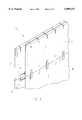
- FIG. 1is a perspective view of a series of form panels connected together with a plurality of the double ties of the present invention, ready to receive concrete;
- FIG. 2is an enlarged perspective view of the double tie of the present invention
- FIG. 3is a view similar to FIG. 1, but with the tie pivoted to a transport position;
- FIG. 4is an enlarged top elevational view of FIG. 3, with a second position of the tie shown in broken lines;
- FIG. 5is a perspective view of a second embodiment of the tie.
- FIG. 6is a perspective view of the second embodiment of the tie installed on form panels.
- the tie of the present inventionis designated generally at 10, and a plurality of ties 10 are shown interconnecting a plurality of form panels 12, 14, 16, and 18.
- Form panels 12, 14, 16, and 18are identical, and therefore only panel 12 will be described in detail.
- Form panel 12includes an upper edge 12a, a lower edge 12b, a side edge 12c, and an opposing side edge 12d.
- Panel 12also includes an outward face 12e and an inward face 12f.
- a plurality of tie slots 20are cut into the upper edge 12a of panel 12, and extend downwardly to receive a lower half of tie 10 therein.
- Upper tie slots 20are uniformly spaced apart along the upper edge of panel 12.
- a plurality of lower tie slots 22are formed along the lower edge of panel 12, vertically aligned with upper tie slots 20, to receive an upper half of ties 10 therein.
- Panels 14, 16, and 18include similar upper and lower tie slots which will align with the tie slots in the horizontally opposing panel, as well as vertically adjacent panels to receive ties 10.
- double tie 10includes a pair of upper and lower elongated connector straps 24 and 26, oriented parallel to one another and connected at their opposing ends to opposing vertical plates 28 and 30.
- the opposing ends 24a and 24b of strap 24are enlarged in the vertical dimension, to provide greater structural strength.
- Three parallel horizontal legs 32a, 32b, and 32cproject outwardly from the end 24b of strap 24, and are vertically spaced apart. Legs 32a, b, and c are rigidly connected to plate 30 to form a general "T" shape in horizontal cross-section.
- legs 32a and 32b, and between legs 32b and 32care shown as openings in the drawings, it should be understood that these openings could be filled with material to form a solid panel connecting strap 24 to plate 30. Openings, or a thin sheet of material is preferred, such that legs 32a, 32b, and 32c are formed.
- the use of small cross-sectional legs 32a, b, and cpermits plate 30 to be more easily removed from the end of strap 24 by breaking the legs 32a, b, and c.
- the opposing end 24a of upper strap 24also has a plurality of legs 34a, 34b, and 34c similar to legs 32a, b, and c, but projecting in the opposite direction. Legs 34a, b, and c connect end 24a with plate 28, as shown in the drawings.
- a living hinge 36is formed in strap end 24a by a pair of diametric, vertically oriented grooves 38. Hinge 36 permits pivotal movement of strap 24 about hinge 36, along a pivot axis parallel to plate 28. Hinge 36 is spaced away from plate 28 a distance slightly greater than the thickness of the form panel upon which tie 10 will be used, such that strap 24 is pivotable once tie 10 is attached to the form panel.
- a similar hinge 40is formed in the opposing end 24b of strap 24 spaced away from plate 30 a distance equal to the distance which hinge 36 is spaced from plate 28.
- Hinges 36 and 40have parallel pivotal axes, which in turn are parallel with plates 28 and 30.
- a pair of spaced apart pegs 42project upwardly and downwardly from strap 24, and are generally centered between strap ends 24a and 24b. Pegs 42 are used to position and align reinforcement bar between form panels.
- Strap 26is identical to strap 24, and includes all of the same components described above, which therefore will not be described in detail.
- strap 26includes enlarged ends 26a and 26b, hinges 44 and 46, and a plurality of legs 48a, 48b, and 48c, and 50a, 50b, and 50c.
- Hinge 44is vertically aligned with hinge 36 on upper strap 24, and lower strap hinge 46 is similarly vertically aligned with upper strap hinge 40.
- Lower strap 26also includes pairs of pegs 52 projecting upwardly and downwardly from strap 26 and aligned with pegs 42 on upper strap 24.
- a T-shaped stop strap 54is mounted on the inward face 28a of plate 28, and projects inwardly therefrom, parallel to upper and lower straps 24 and 26, and centered therebetween.
- Stop strap 54includes a stem 56 projecting from plate 28, and a head 58 extending orthogonally relative to stem 56 to form the "T" shape. Head 58 is located in general alignment with upper stem hinge 36 and lower stem hinge 44, and serves to prevent form panels from being pushed inwardly away from plate 28.
- a similar stop strap 60is positioned opposite stop strap 54, on the inward face 30a of plate 30, between upper and lower straps 24 and 26. Stop strap 60 also includes a stem 62 and a head 64, the same as stop strap 54.
- each tie 10is used by inserting the ends of the lower strap 26 in to the upper tie slots 20 on pairs of opposing panels 12 and 16, and opposing panels 14 and 18.
- the depth of slots 20is predetermined, such that tie 10 will contact the bottom of upper slots 20 when the upper edges of the form panels are positioned half way up on stop straps 54 and 60.
- the stop strap heads 58 and 64will have a lower portion retaining a pair of lower opposing panels from inward movement, and an upper portion retaining the lower edge of a pair of upper form panels from moving inwardly.
- each tie 10will interconnect two pairs of horizontally opposed form panels in vertical alignment, to permit the formation of a concrete wall therebetween.
- each tie 10is designed to permit pivotal movement about two vertical axes formed by pairs of hinges 36 and 44, and 40 and 46.
- This pivoting or folding capabilitypermits the form panels 12, 14, 16, and 18 to be assembled into a form unit, designated generally at 66 in FIG. 3, and then moved to a compact orientation with the upper form panels 12 and 16 proximal one another and the lower form panels 14 and 18 proximal one another.
- thisdramatically reduces the space requirement for transport of an assembled unit 66, and thereby increases the economic feasibility of shipping the form units 66 in an assembled condition, rather than as a set of unconnected components.
- Shipment as an assembled unitdramatically decreases the set up time at the job site, thereby decreasing the cost of use of the system.
- a second embodiment of the tieis designated generally at 10' and is identical to the first embodiment of the tie 10, except that hinges 36, 40, 44, and 46 are not formed into the tie.
- upper and lower straps 24' and 26'remain in an orthogonal orientation connected to plates 28' and 30', whereas the straps 24 and 26 of tie 10 may be moved to a generally parallel orientation relative to plates 28 and 30, during transport.
Landscapes
- Engineering & Computer Science (AREA)
- Architecture (AREA)
- Physics & Mathematics (AREA)
- Electromagnetism (AREA)
- Civil Engineering (AREA)
- Structural Engineering (AREA)
- Forms Removed On Construction Sites Or Auxiliary Members Thereof (AREA)
Abstract
Description
The present invention relates generally to ties for concrete wall systems, and more particularly to an improved tie for interconnecting vertical pairs of form panels and opposing horizontally spaced pairs of parallel form panels.
The use of expanded polystyrene panels as forms for poured concrete walls has become quite common in the industry. After the concrete has hardened between the form panels, the panels may be left in place on the walls to serve as permanent insulation, where they may be stripped off of the concrete walls to reveal the exposed concrete.
As new developments occur in this industry, larger and longer panels are being utilized to create the concrete forms of the forming system. In addition, methods have been continuously developed for increasing the speed of constructing the forms, and reducing the overall cost of the form system.
One particular feature of current form systems calls for the placement of connecting ties at uniformly spaced apart locations along the length of the upper and lower edges of each form panel. This can be quite time consuming, and thereby contributes to the cost of use of this type of form system.
Transportation of preassembled units is typically not economical because of the great amount of space required when the ties hold the form panels spaced apart from one another.
It is therefore a general object of the present invention to provide an improved tie for use with polystyrene panel-type forms in poured concrete wall forming systems.
Another object is to provide a concrete wall form tie which will rigidly hold the form panels necessary to construct a poured concrete wall.
A further object of the present invention is to provide a double tie which may be attached to the adjoining lower and upper edges of a pair of vertically aligned form panels to interconnect the panels together, while interconnecting these form panels with an opposing horizontally spaced pair of form panels.
Yet another object is to provide a tie which may be folded, to permit an assembled unit to be pivoted to an orientation with the form panels immediately adjacent one another, thereby conserving space.
These and other objects of the present invention will be apparent to those skilled in the art.
The double tie of the present invention includes a pair of upper and lower straps connected in parallel relationship by a pair of vertical plates attached to the outward ends of the straps. The plates are oriented orthogonally relative to the straps to form a general "T" shape. A pair of stop straps are mounted on the plates intermediate the upper and lower straps, and projecting towards one another. The stop straps have orthogonal heads spaced inwardly from the plates a distance to retain a form panel between the head and plate. Each upper and lower strap has a hinge formed at each end, the hinges at each end of the upper and lower straps being coaxial and parallel to the plates, such that the upper and lower straps may be pivoted from a position generally orthogonal to the plates, to a position generally parallel to the plates.
FIG. 1 is a perspective view of a series of form panels connected together with a plurality of the double ties of the present invention, ready to receive concrete;
FIG. 2 is an enlarged perspective view of the double tie of the present invention;
FIG. 3 is a view similar to FIG. 1, but with the tie pivoted to a transport position;
FIG. 4 is an enlarged top elevational view of FIG. 3, with a second position of the tie shown in broken lines;
FIG. 5 is a perspective view of a second embodiment of the tie; and
FIG. 6 is a perspective view of the second embodiment of the tie installed on form panels.
Referring now to the drawings, in which similar or corresponding parts are identified with the same reference numeral and more particularly to FIG. 1, the tie of the present invention is designated generally at 10, and a plurality ofties 10 are shown interconnecting a plurality ofform panels
Referring now to FIG. 2,double tie 10 includes a pair of upper and lowerelongated connector straps vertical plates opposing ends 24a and 24b ofstrap 24 are enlarged in the vertical dimension, to provide greater structural strength. Three parallelhorizontal legs strap 24, and are vertically spaced apart. Legs 32a, b, and c are rigidly connected toplate 30 to form a general "T" shape in horizontal cross-section. While the spaces betweenlegs legs panel connecting strap 24 toplate 30. Openings, or a thin sheet of material is preferred, such thatlegs cross-sectional legs 32a, b, and c permitsplate 30 to be more easily removed from the end ofstrap 24 by breaking thelegs 32a, b, and c.
Theopposing end 24a ofupper strap 24 also has a plurality oflegs 34a, 34b, and 34c similar tolegs 32a, b, and c, but projecting in the opposite direction. Legs 34a, b, and c connectend 24a withplate 28, as shown in the drawings.
Aliving hinge 36 is formed instrap end 24a by a pair of diametric, vertically orientedgrooves 38. Hinge 36 permits pivotal movement ofstrap 24 abouthinge 36, along a pivot axis parallel toplate 28.Hinge 36 is spaced away fromplate 28 a distance slightly greater than the thickness of the form panel upon whichtie 10 will be used, such thatstrap 24 is pivotable oncetie 10 is attached to the form panel.
Asimilar hinge 40 is formed in the opposing end 24b ofstrap 24 spaced away fromplate 30 a distance equal to the distance whichhinge 36 is spaced fromplate 28. Hinges 36 and 40 have parallel pivotal axes, which in turn are parallel withplates
A pair of spaced apart pegs 42 project upwardly and downwardly fromstrap 24, and are generally centered betweenstrap ends 24a and 24b.Pegs 42 are used to position and align reinforcement bar between form panels.
A T-shaped stop strap 54 is mounted on theinward face 28a ofplate 28, and projects inwardly therefrom, parallel to upper andlower straps Stop strap 54 includes astem 56 projecting fromplate 28, and ahead 58 extending orthogonally relative to stem 56 to form the "T" shape.Head 58 is located in general alignment withupper stem hinge 36 andlower stem hinge 44, and serves to prevent form panels from being pushed inwardly away fromplate 28. Asimilar stop strap 60 is positionedopposite stop strap 54, on theinward face 30a ofplate 30, between upper andlower straps Stop strap 60 also includes astem 62 and ahead 64, the same asstop strap 54.
Referring once again to FIG. 1, it can be seen that eachtie 10 is used by inserting the ends of thelower strap 26 in to theupper tie slots 20 on pairs ofopposing panels panels slots 20 is predetermined, such thattie 10 will contact the bottom ofupper slots 20 when the upper edges of the form panels are positioned half way up onstop straps stop strap heads
Once a plurality ofties 10 have been inserted in theupper slots 20 on a pair of opposing form panels, an additional pair of form panels are connected in vertical alignment with the lower pair of form panels, by inserting thelower tie slots 22 of each form panel on the opposing ends of theupper straps 24 ofties 10. Once positioned between the form panels,outer plates tie 10 will interconnect two pairs of horizontally opposed form panels in vertical alignment, to permit the formation of a concrete wall therebetween.
Referring now to FIGS. 3 and 4, eachtie 10 is designed to permit pivotal movement about two vertical axes formed by pairs ofhinges form panels upper form panels lower form panels unit 66, and thereby increases the economic feasibility of shipping theform units 66 in an assembled condition, rather than as a set of unconnected components. Shipment as an assembled unit dramatically decreases the set up time at the job site, thereby decreasing the cost of use of the system.
Referring now to FIGS. 5 and 6, a second embodiment of the tie is designated generally at 10' and is identical to the first embodiment of thetie 10, except that hinges 36, 40, 44, and 46 are not formed into the tie. Thus, upper and lower straps 24' and 26' remain in an orthogonal orientation connected to plates 28' and 30', whereas thestraps tie 10 may be moved to a generally parallel orientation relative toplates
Whereas the invention has been shown and described in connection with the preferred embodiment thereof, many modifications, substitutions and additions may be made which are within the intended broad scope of the appended claims.
Claims (9)
1. In combination:
a first pair of parallel, horizontally spaced apart form panels, having upper and lower edges and inward and outward faces;
a second pair of parallel, horizontally spaced apart form panels, vertically aligned with the first pair of form panels, having upper and lower edges and inward and outward faces;
a plurality of upper tie slots formed downwardly into the upper edges of each of the first and second pairs of form panels;
a plurality of lower tie slots formed upwardly into the lower edges of each of the first and second pairs of form panels;
said first pair of form panels located atop the second pair of form panels with the lower slots in the first pair of form panels aligned vertically with the upper slots in the second pair of form panels; and
a plurality of ties connecting the panels of each of the first and second pairs of form panels together, and connecting the first pair of panels in vertical alignment with the second pair of panels;
each said tie including:
an upper tie strap extending between and inserted through a lower tie slot in each of said first pair of form panels;
a lower tie strap extending between and inserted through an upper tie slot in each of said second pair of form panels;
a first plate connecting first ends of the upper and lower tie straps; and
a second plate connecting second ends of the upper and lower tie straps;
said first and second plates being positioned against the outward faces of the panels to prevent outward movement of the panels off of the upper and lower straps, and further comprising:
first and second stop straps mounted on the first and second plates and projecting towards one another;
said stop straps having coaxial elongated stems and a head at a free inward end of the stems; and
said heads oriented orthogonally relative to the stems and parallel to one another, and positioned against the inward faces of the panels to prevent inward movement of the panels along the upper and lower straps.
2. The combination of claim 1, wherein each strap includes a hinge located inward and proximal the inward faces of the panels, the hinges on the upper strap having axes coaxial with axes of the hinges on the lower strap.
3. A tie for retaining two pairs of parallel, horizontally opposed, form panels in vertical alignment, comprising;
upper and lower horizontal and parallel elongated straps connected together at opposing first and second ends by first and second elongated vertically oriented plates;
said plates being oriented orthogonally relative to the straps to form a "T" shape connection at each end of said straps; and
first and second stop straps mounted on the first and second plates and projecting towards one another, said stop straps having coaxial, elongated stems, and a head at a free inward end of the stems, the heads oriented orthogonally relative to the stems and parallel to one another.
4. The tie of claim 3, wherein said first and second stop straps have stems of equal length.
5. The tie of claim 4, wherein the ends of said upper and lower straps are enlarged in a vertical direction and coplanar.
6. The tie of claim 5, wherein each strap end is connected to said plates by at least two spaced apart coplanar legs.
7. The tie of claim 6, wherein each strap end includes a vertically oriented hinge spaced away and parallel to said plates, said hinges permitting pivotal movement of the straps from positions generally orthogonal to the plates to positions generally parallel to the plates.
8. The tie of claim 7, wherein the hinges on the upper strap ends have axes coaxial with axes of the hinges on the lower strap ends.
9. The tie of claim 8, wherein said hinge axes are spaced from the plate proximal thereto a distance substantially the same as the length of the stop strap stem proximal to the hinge axes.
Priority Applications (1)
| Application Number | Priority Date | Filing Date | Title |
|---|---|---|---|
| US08/949,967US5890337A (en) | 1997-10-14 | 1997-10-14 | Double tie |
Applications Claiming Priority (1)
| Application Number | Priority Date | Filing Date | Title |
|---|---|---|---|
| US08/949,967US5890337A (en) | 1997-10-14 | 1997-10-14 | Double tie |
Publications (1)
| Publication Number | Publication Date |
|---|---|
| US5890337Atrue US5890337A (en) | 1999-04-06 |
Family
ID=25489760
Family Applications (1)
| Application Number | Title | Priority Date | Filing Date |
|---|---|---|---|
| US08/949,967Expired - Fee RelatedUS5890337A (en) | 1997-10-14 | 1997-10-14 | Double tie |
Country Status (1)
| Country | Link |
|---|---|
| US (1) | US5890337A (en) |
Cited By (79)
| Publication number | Priority date | Publication date | Assignee | Title |
|---|---|---|---|---|
| RU2153561C1 (en)* | 1999-05-07 | 2000-07-27 | Килесов Владимир Яковлевич | Method of erecting building structures |
| USD435212S (en)* | 1998-09-02 | 2000-12-19 | Phil-Insul Corporation | Spacer |
| US6176059B1 (en)* | 1998-11-20 | 2001-01-23 | Robert A. Cantarano | Modular concrete building system |
| US6224031B1 (en)* | 1999-05-13 | 2001-05-01 | Patrick E. Boeshart | Tie with hinged end plates |
| US6230462B1 (en)* | 1998-12-23 | 2001-05-15 | BéLIVEAU JEAN-LOUIS | Concrete wall form and connectors therefor |
| US6256962B1 (en)* | 2000-01-12 | 2001-07-10 | Patrick E. Boeshart | Tie for reusable form panels |
| US6263638B1 (en)* | 1999-06-17 | 2001-07-24 | Composite Technologies Corporation | Insulated integral concrete wall forming system |
| US6314697B1 (en)* | 1998-10-26 | 2001-11-13 | James D. Moore, Jr. | Concrete form system connector link and method |
| US6324804B1 (en) | 1999-01-15 | 2001-12-04 | Plasti—FAB (division of PFB Corporation) | Concrete wall forming system |
| US6336301B1 (en)* | 1998-11-05 | 2002-01-08 | James D. Moore, Jr. | Concrete form system ledge assembly and method |
| US6363683B1 (en) | 1998-01-16 | 2002-04-02 | James Daniel Moore, Jr. | Insulated concrete form |
| WO2002055812A1 (en)* | 2001-01-11 | 2002-07-18 | Patrick Joseph Scallan | Moulding of concrete walls |
| US6438918B2 (en) | 1998-01-16 | 2002-08-27 | Eco-Block | Latching system for components used in forming concrete structures |
| WO2002033184A3 (en)* | 2000-10-19 | 2002-11-07 | Reward Walls Systems Inc | Prefabricated foam block concrete forms and ties molded therein |
| US6481178B2 (en) | 1998-01-16 | 2002-11-19 | Eco-Block, Llc | Tilt-up wall |
| AU756073B2 (en)* | 2001-01-11 | 2003-01-02 | Patrick Joseph Scallan | Moulding of concrete walls |
| US6647686B2 (en) | 2001-03-09 | 2003-11-18 | Daniel D. Dunn | System for constructing insulated concrete structures |
| US20040040240A1 (en)* | 2002-09-03 | 2004-03-04 | Murray Patz | Insulated concrete wall system |
| US20040045238A1 (en)* | 2001-03-09 | 2004-03-11 | Dunn Daniel D. | Reinforced composite system for constructing insulated concrete structures |
| US20040075040A1 (en)* | 2001-01-11 | 2004-04-22 | Scallan Patrick Joseph | Moulding of concrete walls |
| US20040216415A1 (en)* | 2003-02-04 | 2004-11-04 | Pfeiffer Henry E. | Welded wire reinforcement for modular concrete forms |
| US20050108963A1 (en)* | 2002-12-02 | 2005-05-26 | Wostal Terry K. | Collapsible concrete forms |
| US20050120659A1 (en)* | 2003-12-08 | 2005-06-09 | Nickerson David L. | Wall system with masonry external surface and associated method |
| US6931806B2 (en) | 2003-04-14 | 2005-08-23 | Timothy A. Olsen | Concrete forming system and method |
| US7024833B1 (en)* | 1998-10-19 | 2006-04-11 | International Steel Corporation | Bracket for concrete forms |
| DE10124756B4 (en)* | 2000-12-21 | 2006-04-27 | Hafellner, Reinhard, Dipl.-Ing. | wall system |
| US20060201090A1 (en)* | 2005-02-25 | 2006-09-14 | Tricia Guevara | Lightweight compositions and articles containing such |
| US20060251851A1 (en)* | 2005-02-25 | 2006-11-09 | Jay Bowman | Composite pre-formed construction articles |
| US20060248832A1 (en)* | 2005-05-06 | 2006-11-09 | Shidler David C | Concrete wall form tie |
| WO2006131144A1 (en)* | 2005-06-09 | 2006-12-14 | Pontarolo Engineering S.P.A. | Insulating lost formwork |
| US20070113505A1 (en)* | 2005-11-18 | 2007-05-24 | Polyform A.G.P. Inc. | Stackable construction panel intersection assembly |
| US20070175155A1 (en)* | 2006-01-19 | 2007-08-02 | Plasti-Fab Ltd. | Form for concrete walls |
| RU2306391C1 (en)* | 2006-04-10 | 2007-09-20 | Общество с ограниченной ответственностью "Прогрессивные Строительные Технологии" | Retained form tie |
| US20070278381A1 (en)* | 2006-05-30 | 2007-12-06 | Marker Guy L | Exterior wall construction |
| US20080066408A1 (en)* | 2006-09-14 | 2008-03-20 | Blain Hileman | Insulated concrete form |
| US20080092472A1 (en)* | 2006-10-18 | 2008-04-24 | Reward Wall Systems, Inc. | Adjustable masonry anchor assembly for use with insulating concrete form systems |
| US20080107852A1 (en)* | 2006-11-08 | 2008-05-08 | Rubb Justin D | Foamed plastic structures |
| US20080104911A1 (en)* | 2006-11-08 | 2008-05-08 | Jarvie Shawn P | Insulated concrete form |
| US20080104912A1 (en)* | 2006-11-08 | 2008-05-08 | Ginawati Au | Insulated concrete form |
| US20080172973A1 (en)* | 2007-01-22 | 2008-07-24 | Ideas Without Borders Inc, | System for reinforcing a building structural component |
| US7409801B2 (en) | 2004-03-16 | 2008-08-12 | Tritex Icf Products, Inc. | Prefabricated foam block concrete forms with open tooth connection means |
| US20080250739A1 (en)* | 2006-11-08 | 2008-10-16 | Nova Chemicals Inc. | Foamed plastic structures |
| US20090013629A1 (en)* | 2007-07-09 | 2009-01-15 | Boeshart Patrick E | Method and Apparatus for Using Foam Panels As Forms For Making Concrete Walls |
| US20090107074A1 (en)* | 2007-07-09 | 2009-04-30 | Boeshart Patrick E | Method and Apparatus for Using Foam Panels as Forms for Making Concrete Walls |
| US20090120027A1 (en)* | 2007-11-08 | 2009-05-14 | Victor Amend | Concrete form tie with connector for finishing panel |
| EP2060704A1 (en)* | 2007-11-13 | 2009-05-20 | B.T. Innovation GmbH | Anchor device |
| US20090202307A1 (en)* | 2008-02-11 | 2009-08-13 | Nova Chemicals Inc. | Method of constructing an insulated shallow pier foundation building |
| US20090313914A1 (en)* | 2008-06-20 | 2009-12-24 | Nova Chemicals, Inc.. | Footer cleat for insulating concrete form |
| US20100088984A1 (en)* | 2005-02-25 | 2010-04-15 | Nova Chemicals Inc. | Lightweight compositions and articles containing such |
| US7699929B2 (en) | 2005-03-22 | 2010-04-20 | Nova Chemicals Inc. | Lightweight concrete compositions |
| US7765765B1 (en)* | 2006-06-30 | 2010-08-03 | Perronne Eugene R | Method of assembling polystyrene forms for building foundations |
| US7861479B2 (en) | 2005-01-14 | 2011-01-04 | Airlite Plastics, Co. | Insulated foam panel forms |
| US8048219B2 (en) | 2007-09-20 | 2011-11-01 | Nova Chemicals Inc. | Method of placing concrete |
| US20130081353A1 (en)* | 2008-08-19 | 2013-04-04 | David Jensen | Wall assembly method |
| NO333321B1 (en)* | 2007-09-17 | 2013-05-06 | Broedr Sunde As | Building element for use as formwork and insulation element for erection of foundation wall |
| US20130239499A1 (en)* | 2010-11-25 | 2013-09-19 | Michele Caboni | Variable-geometry modular structure composed of thermo-acoustic caissons, particularly for buildings |
| US20140215949A1 (en)* | 2013-02-04 | 2014-08-07 | Andre Cossette | 65 db SOUND BARRIER INSULATED BLOCK |
| USD713975S1 (en) | 2012-07-30 | 2014-09-23 | Airlite Plastics Co. | Insulative insert for insulated concrete form |
| US8887465B2 (en) | 2012-01-13 | 2014-11-18 | Airlite Plastics Co. | Apparatus and method for construction of structures utilizing insulated concrete forms |
| US8919067B2 (en) | 2011-10-31 | 2014-12-30 | Airlite Plastics Co. | Apparatus and method for construction of structures utilizing insulated concrete forms |
| US9091089B2 (en) | 2013-03-12 | 2015-07-28 | Icf Mform Llc | Insulating concrete form (ICF) system with tie member modularity |
| US9175486B2 (en) | 2013-03-12 | 2015-11-03 | Icf Mform Llc | Insulating concrete form (ICF) system with modular tie members and associated ICF tooling |
| GB2512882B (en)* | 2013-04-10 | 2015-11-11 | Twinfall Icf Ltd | Formwork system |
| US9234347B2 (en) | 2013-02-04 | 2016-01-12 | Andŕe Cossette | Crossed ties for construction block assembly |
| US20160281361A1 (en)* | 2013-12-17 | 2016-09-29 | Benjamin Baader | Insulated concrete panel form and method of making same |
| US20180209114A1 (en)* | 2015-07-22 | 2018-07-26 | James Foley | Trench box and method of assembly |
| US10132080B2 (en)* | 2017-02-21 | 2018-11-20 | Iconx, Llc | Insulated concrete panel tie |
| US10378223B2 (en) | 2013-03-15 | 2019-08-13 | Abt, Inc. | Interlocking form assembly |
| USD856122S1 (en) | 2018-07-13 | 2019-08-13 | Hk Marketing Lc | Tie |
| USD856121S1 (en)* | 2018-01-29 | 2019-08-13 | Hk Marketing Lc | Composite action tie |
| US10378204B2 (en)* | 2015-03-27 | 2019-08-13 | Ambe Engineering Pty Ltd | System for forming an insulated structural concrete wall |
| US10787827B2 (en) | 2016-11-14 | 2020-09-29 | Airlite Plastics Co. | Concrete form with removable sidewall |
| US10870988B2 (en) | 2018-01-29 | 2020-12-22 | Hk Marketing Lc | Tie for composite wall system fitting between insulation sheets |
| US11155995B2 (en) | 2018-11-19 | 2021-10-26 | Airlite Plastics Co. | Concrete form with removable sidewall |
| US20220112712A1 (en)* | 2020-10-14 | 2022-04-14 | Isaac Walker | Construction Block |
| USD968199S1 (en) | 2019-04-23 | 2022-11-01 | Hk Marketing Lc | Tie standoff |
| AU2023201053B1 (en)* | 2023-02-23 | 2024-01-25 | Fabio Parodi | Improvements in and relating to concrete |
| US12017380B2 (en) | 2019-01-18 | 2024-06-25 | Benjamin Baader | Adjustable apparatus, system and method for constructing insulated concrete forms |
| CH720412A1 (en)* | 2022-12-29 | 2024-07-15 | Batilook Sarl | Interlocking brick |
Citations (6)
| Publication number | Priority date | Publication date | Assignee | Title |
|---|---|---|---|---|
| US4730422A (en)* | 1985-11-20 | 1988-03-15 | Young Rubber Company | Insulating non-removable type concrete wall forming structure and device and system for attaching wall coverings thereto |
| US4765109A (en)* | 1987-09-25 | 1988-08-23 | Boeshart Patrick E | Adjustable tie |
| US4884382A (en)* | 1988-05-18 | 1989-12-05 | Horobin David D | Modular building-block form |
| US4889310A (en)* | 1988-05-26 | 1989-12-26 | Boeshart Patrick E | Concrete forming system |
| US5039058A (en)* | 1990-07-10 | 1991-08-13 | Boeshart Patrick E | Hinged tie for forming angles walls |
| USD378049S (en) | 1996-03-14 | 1997-02-18 | Boeshart Patrick E | Tie for concrete forming system |
- 1997
- 1997-10-14USUS08/949,967patent/US5890337A/ennot_activeExpired - Fee Related
Patent Citations (6)
| Publication number | Priority date | Publication date | Assignee | Title |
|---|---|---|---|---|
| US4730422A (en)* | 1985-11-20 | 1988-03-15 | Young Rubber Company | Insulating non-removable type concrete wall forming structure and device and system for attaching wall coverings thereto |
| US4765109A (en)* | 1987-09-25 | 1988-08-23 | Boeshart Patrick E | Adjustable tie |
| US4884382A (en)* | 1988-05-18 | 1989-12-05 | Horobin David D | Modular building-block form |
| US4889310A (en)* | 1988-05-26 | 1989-12-26 | Boeshart Patrick E | Concrete forming system |
| US5039058A (en)* | 1990-07-10 | 1991-08-13 | Boeshart Patrick E | Hinged tie for forming angles walls |
| USD378049S (en) | 1996-03-14 | 1997-02-18 | Boeshart Patrick E | Tie for concrete forming system |
Cited By (116)
| Publication number | Priority date | Publication date | Assignee | Title |
|---|---|---|---|---|
| US6481178B2 (en) | 1998-01-16 | 2002-11-19 | Eco-Block, Llc | Tilt-up wall |
| US6438918B2 (en) | 1998-01-16 | 2002-08-27 | Eco-Block | Latching system for components used in forming concrete structures |
| US6526713B2 (en) | 1998-01-16 | 2003-03-04 | Eco-Block, Llc | Concrete structure |
| US6363683B1 (en) | 1998-01-16 | 2002-04-02 | James Daniel Moore, Jr. | Insulated concrete form |
| US6609340B2 (en) | 1998-01-16 | 2003-08-26 | Eco-Block, Llc | Concrete structures and methods of forming the same using extenders |
| USD435212S (en)* | 1998-09-02 | 2000-12-19 | Phil-Insul Corporation | Spacer |
| US20150052839A1 (en)* | 1998-10-19 | 2015-02-26 | International Steel Corporation | Bracket for concrete forms |
| US9038338B2 (en)* | 1998-10-19 | 2015-05-26 | Bailey Metal Products Limited | Insulated concrete form wall having a bracket attaching a rim joist thereto |
| US7024833B1 (en)* | 1998-10-19 | 2006-04-11 | International Steel Corporation | Bracket for concrete forms |
| US6314697B1 (en)* | 1998-10-26 | 2001-11-13 | James D. Moore, Jr. | Concrete form system connector link and method |
| US6336301B1 (en)* | 1998-11-05 | 2002-01-08 | James D. Moore, Jr. | Concrete form system ledge assembly and method |
| US6176059B1 (en)* | 1998-11-20 | 2001-01-23 | Robert A. Cantarano | Modular concrete building system |
| US6230462B1 (en)* | 1998-12-23 | 2001-05-15 | BéLIVEAU JEAN-LOUIS | Concrete wall form and connectors therefor |
| US6324804B1 (en) | 1999-01-15 | 2001-12-04 | Plasti—FAB (division of PFB Corporation) | Concrete wall forming system |
| RU2153561C1 (en)* | 1999-05-07 | 2000-07-27 | Килесов Владимир Яковлевич | Method of erecting building structures |
| US6224031B1 (en)* | 1999-05-13 | 2001-05-01 | Patrick E. Boeshart | Tie with hinged end plates |
| US6263638B1 (en)* | 1999-06-17 | 2001-07-24 | Composite Technologies Corporation | Insulated integral concrete wall forming system |
| US6256962B1 (en)* | 2000-01-12 | 2001-07-10 | Patrick E. Boeshart | Tie for reusable form panels |
| WO2002033184A3 (en)* | 2000-10-19 | 2002-11-07 | Reward Walls Systems Inc | Prefabricated foam block concrete forms and ties molded therein |
| US6820384B1 (en) | 2000-10-19 | 2004-11-23 | Reward Wall Systems, Inc. | Prefabricated foam block concrete forms and ties molded therein |
| DE10124756B4 (en)* | 2000-12-21 | 2006-04-27 | Hafellner, Reinhard, Dipl.-Ing. | wall system |
| AU756073B2 (en)* | 2001-01-11 | 2003-01-02 | Patrick Joseph Scallan | Moulding of concrete walls |
| WO2002055812A1 (en)* | 2001-01-11 | 2002-07-18 | Patrick Joseph Scallan | Moulding of concrete walls |
| US20040075040A1 (en)* | 2001-01-11 | 2004-04-22 | Scallan Patrick Joseph | Moulding of concrete walls |
| US6647686B2 (en) | 2001-03-09 | 2003-11-18 | Daniel D. Dunn | System for constructing insulated concrete structures |
| US20040045238A1 (en)* | 2001-03-09 | 2004-03-11 | Dunn Daniel D. | Reinforced composite system for constructing insulated concrete structures |
| US6935081B2 (en) | 2001-03-09 | 2005-08-30 | Daniel D. Dunn | Reinforced composite system for constructing insulated concrete structures |
| US20040040240A1 (en)* | 2002-09-03 | 2004-03-04 | Murray Patz | Insulated concrete wall system |
| US20060260240A1 (en)* | 2002-09-03 | 2006-11-23 | Murray Patz | Insulated concrete wall system |
| US7082731B2 (en)* | 2002-09-03 | 2006-08-01 | Murray Patz | Insulated concrete wall system |
| US20050108963A1 (en)* | 2002-12-02 | 2005-05-26 | Wostal Terry K. | Collapsible concrete forms |
| US6915613B2 (en) | 2002-12-02 | 2005-07-12 | Cellox Llc | Collapsible concrete forms |
| US7347029B2 (en) | 2002-12-02 | 2008-03-25 | Wostal Terry K | Collapsible concrete forms |
| US7437858B2 (en)* | 2003-02-04 | 2008-10-21 | Reward Wall System, Inc. | Welded wire reinforcement for modular concrete forms |
| US20040216415A1 (en)* | 2003-02-04 | 2004-11-04 | Pfeiffer Henry E. | Welded wire reinforcement for modular concrete forms |
| US6931806B2 (en) | 2003-04-14 | 2005-08-23 | Timothy A. Olsen | Concrete forming system and method |
| US20050120659A1 (en)* | 2003-12-08 | 2005-06-09 | Nickerson David L. | Wall system with masonry external surface and associated method |
| US7415805B2 (en) | 2003-12-08 | 2008-08-26 | Nickerson David L | Wall system with masonry external surface and associated method |
| US7409801B2 (en) | 2004-03-16 | 2008-08-12 | Tritex Icf Products, Inc. | Prefabricated foam block concrete forms with open tooth connection means |
| US7861479B2 (en) | 2005-01-14 | 2011-01-04 | Airlite Plastics, Co. | Insulated foam panel forms |
| US7666258B2 (en) | 2005-02-25 | 2010-02-23 | Nova Chemicals Inc. | Lightweight compositions and articles containing such |
| US8752348B2 (en) | 2005-02-25 | 2014-06-17 | Syntheon Inc. | Composite pre-formed construction articles |
| US20060201090A1 (en)* | 2005-02-25 | 2006-09-14 | Tricia Guevara | Lightweight compositions and articles containing such |
| US20110138725A1 (en)* | 2005-02-25 | 2011-06-16 | Nova Chemicals Inc. | Composite pre-formed construction articles |
| US7963080B1 (en) | 2005-02-25 | 2011-06-21 | Nova Chemicals Inc. | Composite pre-formed construction articles |
| US20060251851A1 (en)* | 2005-02-25 | 2006-11-09 | Jay Bowman | Composite pre-formed construction articles |
| US7790302B2 (en) | 2005-02-25 | 2010-09-07 | Nova Chemicals Inc. | Lightweight compositions and articles containing such |
| US20100088984A1 (en)* | 2005-02-25 | 2010-04-15 | Nova Chemicals Inc. | Lightweight compositions and articles containing such |
| US7964272B2 (en) | 2005-02-25 | 2011-06-21 | Nova Chemicals Inc. | Lightweight compositions and articles containing such |
| US7699929B2 (en) | 2005-03-22 | 2010-04-20 | Nova Chemicals Inc. | Lightweight concrete compositions |
| USRE43253E1 (en) | 2005-03-22 | 2012-03-20 | Nova Chemicals Inc. | Lightweight concrete compositions |
| US20060248832A1 (en)* | 2005-05-06 | 2006-11-09 | Shidler David C | Concrete wall form tie |
| WO2006131144A1 (en)* | 2005-06-09 | 2006-12-14 | Pontarolo Engineering S.P.A. | Insulating lost formwork |
| US20070113505A1 (en)* | 2005-11-18 | 2007-05-24 | Polyform A.G.P. Inc. | Stackable construction panel intersection assembly |
| US20070175155A1 (en)* | 2006-01-19 | 2007-08-02 | Plasti-Fab Ltd. | Form for concrete walls |
| RU2306391C1 (en)* | 2006-04-10 | 2007-09-20 | Общество с ограниченной ответственностью "Прогрессивные Строительные Технологии" | Retained form tie |
| US20070278381A1 (en)* | 2006-05-30 | 2007-12-06 | Marker Guy L | Exterior wall construction |
| US7765765B1 (en)* | 2006-06-30 | 2010-08-03 | Perronne Eugene R | Method of assembling polystyrene forms for building foundations |
| US20080066408A1 (en)* | 2006-09-14 | 2008-03-20 | Blain Hileman | Insulated concrete form |
| US8347581B2 (en)* | 2006-10-18 | 2013-01-08 | Reward Wall Systems, Inc. | Adjustable masonry anchor assembly for use with insulating concrete form systems |
| US20080092472A1 (en)* | 2006-10-18 | 2008-04-24 | Reward Wall Systems, Inc. | Adjustable masonry anchor assembly for use with insulating concrete form systems |
| US20080250739A1 (en)* | 2006-11-08 | 2008-10-16 | Nova Chemicals Inc. | Foamed plastic structures |
| US7765759B2 (en) | 2006-11-08 | 2010-08-03 | Nova Chemicals Inc. | Insulated concrete form |
| US20080104912A1 (en)* | 2006-11-08 | 2008-05-08 | Ginawati Au | Insulated concrete form |
| US20080104911A1 (en)* | 2006-11-08 | 2008-05-08 | Jarvie Shawn P | Insulated concrete form |
| US20080107852A1 (en)* | 2006-11-08 | 2008-05-08 | Rubb Justin D | Foamed plastic structures |
| US8713887B2 (en)* | 2007-01-22 | 2014-05-06 | Ideas Without Borders Inc. | System for reinforcing a building structural component |
| US20080172973A1 (en)* | 2007-01-22 | 2008-07-24 | Ideas Without Borders Inc, | System for reinforcing a building structural component |
| US20100050551A1 (en)* | 2007-07-09 | 2010-03-04 | Boeshart Patrick E | Method and Apparatus for Using Foam Panels As Forms For Making Concrete Walls |
| US20090107074A1 (en)* | 2007-07-09 | 2009-04-30 | Boeshart Patrick E | Method and Apparatus for Using Foam Panels as Forms for Making Concrete Walls |
| US20090013629A1 (en)* | 2007-07-09 | 2009-01-15 | Boeshart Patrick E | Method and Apparatus for Using Foam Panels As Forms For Making Concrete Walls |
| NO333321B1 (en)* | 2007-09-17 | 2013-05-06 | Broedr Sunde As | Building element for use as formwork and insulation element for erection of foundation wall |
| US8048219B2 (en) | 2007-09-20 | 2011-11-01 | Nova Chemicals Inc. | Method of placing concrete |
| US20090120027A1 (en)* | 2007-11-08 | 2009-05-14 | Victor Amend | Concrete form tie with connector for finishing panel |
| EP2060704A1 (en)* | 2007-11-13 | 2009-05-20 | B.T. Innovation GmbH | Anchor device |
| US20090202307A1 (en)* | 2008-02-11 | 2009-08-13 | Nova Chemicals Inc. | Method of constructing an insulated shallow pier foundation building |
| US7874112B2 (en) | 2008-06-20 | 2011-01-25 | Nova Chemicals Inc. | Footer cleat for insulating concrete form |
| US20090313914A1 (en)* | 2008-06-20 | 2009-12-24 | Nova Chemicals, Inc.. | Footer cleat for insulating concrete form |
| US20130081353A1 (en)* | 2008-08-19 | 2013-04-04 | David Jensen | Wall assembly method |
| US9091055B2 (en)* | 2008-08-19 | 2015-07-28 | Sonoma Cast Stone Corporation | Wall assembly method |
| US20130239499A1 (en)* | 2010-11-25 | 2013-09-19 | Michele Caboni | Variable-geometry modular structure composed of thermo-acoustic caissons, particularly for buildings |
| US8881483B2 (en)* | 2010-11-25 | 2014-11-11 | Michele Caboni | Variable-geometry modular structure composed of thermo-acoustic caissons, particularly for buildings |
| US8919067B2 (en) | 2011-10-31 | 2014-12-30 | Airlite Plastics Co. | Apparatus and method for construction of structures utilizing insulated concrete forms |
| US8887465B2 (en) | 2012-01-13 | 2014-11-18 | Airlite Plastics Co. | Apparatus and method for construction of structures utilizing insulated concrete forms |
| USD713975S1 (en) | 2012-07-30 | 2014-09-23 | Airlite Plastics Co. | Insulative insert for insulated concrete form |
| US20140215949A1 (en)* | 2013-02-04 | 2014-08-07 | Andre Cossette | 65 db SOUND BARRIER INSULATED BLOCK |
| US9151051B2 (en)* | 2013-02-04 | 2015-10-06 | Andre Cossette | 65 db sound barrier insulated block |
| US9234347B2 (en) | 2013-02-04 | 2016-01-12 | Andŕe Cossette | Crossed ties for construction block assembly |
| US9091089B2 (en) | 2013-03-12 | 2015-07-28 | Icf Mform Llc | Insulating concrete form (ICF) system with tie member modularity |
| US9175486B2 (en) | 2013-03-12 | 2015-11-03 | Icf Mform Llc | Insulating concrete form (ICF) system with modular tie members and associated ICF tooling |
| US10378223B2 (en) | 2013-03-15 | 2019-08-13 | Abt, Inc. | Interlocking form assembly |
| GB2512882B (en)* | 2013-04-10 | 2015-11-11 | Twinfall Icf Ltd | Formwork system |
| US20160281361A1 (en)* | 2013-12-17 | 2016-09-29 | Benjamin Baader | Insulated concrete panel form and method of making same |
| US20190093355A1 (en)* | 2013-12-17 | 2019-03-28 | Benjamin Baader | Insulated concrete panel form and method of making same |
| US10006200B2 (en)* | 2013-12-17 | 2018-06-26 | Benjamin Baader | Insulated concrete panel form and method of making same |
| US10378204B2 (en)* | 2015-03-27 | 2019-08-13 | Ambe Engineering Pty Ltd | System for forming an insulated structural concrete wall |
| US11286634B2 (en)* | 2015-07-22 | 2022-03-29 | 2307050 Alberta Ltd. | Trench box and method of assembly |
| US12173464B2 (en)* | 2015-07-22 | 2024-12-24 | 2307050 Alberta Ltd. | Trench box and method of assembly |
| US10604906B2 (en)* | 2015-07-22 | 2020-03-31 | Kames Foley | Trench box and method of assembly |
| US20220220689A1 (en)* | 2015-07-22 | 2022-07-14 | 1814966 Alberta Ltd. | Trench box and method of assembly |
| US20180209114A1 (en)* | 2015-07-22 | 2018-07-26 | James Foley | Trench box and method of assembly |
| US11591813B2 (en) | 2016-11-14 | 2023-02-28 | Airlite Plastics Co. | Concrete form with removable sidewall |
| US10787827B2 (en) | 2016-11-14 | 2020-09-29 | Airlite Plastics Co. | Concrete form with removable sidewall |
| US10132080B2 (en)* | 2017-02-21 | 2018-11-20 | Iconx, Llc | Insulated concrete panel tie |
| US10870988B2 (en) | 2018-01-29 | 2020-12-22 | Hk Marketing Lc | Tie for composite wall system fitting between insulation sheets |
| USD887258S1 (en)* | 2018-01-29 | 2020-06-16 | Hk Marketing Lc | Composite action tie |
| USD856121S1 (en)* | 2018-01-29 | 2019-08-13 | Hk Marketing Lc | Composite action tie |
| USD856122S1 (en) | 2018-07-13 | 2019-08-13 | Hk Marketing Lc | Tie |
| US11155995B2 (en) | 2018-11-19 | 2021-10-26 | Airlite Plastics Co. | Concrete form with removable sidewall |
| US12017380B2 (en) | 2019-01-18 | 2024-06-25 | Benjamin Baader | Adjustable apparatus, system and method for constructing insulated concrete forms |
| USD968199S1 (en) | 2019-04-23 | 2022-11-01 | Hk Marketing Lc | Tie standoff |
| USD1061227S1 (en) | 2019-04-23 | 2025-02-11 | Hk Marketing Lc | Tie standoff |
| US20220112712A1 (en)* | 2020-10-14 | 2022-04-14 | Isaac Walker | Construction Block |
| US11718985B2 (en)* | 2020-10-14 | 2023-08-08 | Isaac Walker | Construction block |
| CH720412A1 (en)* | 2022-12-29 | 2024-07-15 | Batilook Sarl | Interlocking brick |
| AU2023201053B1 (en)* | 2023-02-23 | 2024-01-25 | Fabio Parodi | Improvements in and relating to concrete |
Similar Documents
| Publication | Publication Date | Title |
|---|---|---|
| US5890337A (en) | Double tie | |
| US5704180A (en) | Insulating concrete form utilizing interlocking foam panels | |
| US4889310A (en) | Concrete forming system | |
| US7082731B2 (en) | Insulated concrete wall system | |
| US7818936B2 (en) | Extruded permanent form-work for concrete | |
| US4888931A (en) | Insulating formwork for casting a concrete wall | |
| US6352237B1 (en) | Insulated concrete forming system | |
| US4516372A (en) | Concrete formwork | |
| US6295781B1 (en) | Stud, top plate, and rafter tie down | |
| US8037652B2 (en) | Insulated concrete form | |
| US6279285B1 (en) | Insulated concrete wall system | |
| US5524397A (en) | Framing system for wood frame buildings | |
| US6435471B1 (en) | Modular formwork elements and assembly | |
| US5930958A (en) | Insulated concrete form system | |
| US20030009967A1 (en) | Modular formwork elements and assembly | |
| US7305803B2 (en) | Block construction system | |
| US5039058A (en) | Hinged tie for forming angles walls | |
| US6324804B1 (en) | Concrete wall forming system | |
| CA1304952C (en) | Insulating formwork for concrete wall | |
| US6224031B1 (en) | Tie with hinged end plates | |
| CA2574694C (en) | Double ended connector/utility unit | |
| US6826880B2 (en) | Corner assemblies for concrete form panels | |
| US20040159061A1 (en) | Insulated concrete form system and method for use | |
| US20240076866A1 (en) | Brackets for insulated concrete forms and methods of manufacturing and installation thereof | |
| US12044018B2 (en) | Concrete form assembly |
Legal Events
| Date | Code | Title | Description |
|---|---|---|---|
| FPAY | Fee payment | Year of fee payment:4 | |
| FPAY | Fee payment | Year of fee payment:8 | |
| FEPP | Fee payment procedure | Free format text:PAYOR NUMBER ASSIGNED (ORIGINAL EVENT CODE: ASPN); ENTITY STATUS OF PATENT OWNER: SMALL ENTITY | |
| REMI | Maintenance fee reminder mailed | ||
| LAPS | Lapse for failure to pay maintenance fees | ||
| STCH | Information on status: patent discontinuation | Free format text:PATENT EXPIRED DUE TO NONPAYMENT OF MAINTENANCE FEES UNDER 37 CFR 1.362 | |
| FP | Lapsed due to failure to pay maintenance fee | Effective date:20110406 |