US5889915A - Digital storage device for a television - Google Patents
Digital storage device for a televisionDownload PDFInfo
- Publication number
- US5889915A US5889915AUS08/910,520US91052097AUS5889915AUS 5889915 AUS5889915 AUS 5889915AUS 91052097 AUS91052097 AUS 91052097AUS 5889915 AUS5889915 AUS 5889915A
- Authority
- US
- United States
- Prior art keywords
- signals
- television
- logic bus
- interface logic
- control
- Prior art date
- Legal status (The legal status is an assumption and is not a legal conclusion. Google has not performed a legal analysis and makes no representation as to the accuracy of the status listed.)
- Expired - Lifetime
Links
Images


Classifications
- H—ELECTRICITY
- H04—ELECTRIC COMMUNICATION TECHNIQUE
- H04N—PICTORIAL COMMUNICATION, e.g. TELEVISION
- H04N5/00—Details of television systems
- H04N5/76—Television signal recording
- H04N5/765—Interface circuits between an apparatus for recording and another apparatus
- H04N5/775—Interface circuits between an apparatus for recording and another apparatus between a recording apparatus and a television receiver
- H—ELECTRICITY
- H04—ELECTRIC COMMUNICATION TECHNIQUE
- H04N—PICTORIAL COMMUNICATION, e.g. TELEVISION
- H04N21/00—Selective content distribution, e.g. interactive television or video on demand [VOD]
- H04N21/40—Client devices specifically adapted for the reception of or interaction with content, e.g. set-top-box [STB]; Operations thereof
- H04N21/41—Structure of client; Structure of client peripherals
- H04N21/414—Specialised client platforms, e.g. receiver in car or embedded in a mobile appliance
- H04N21/4147—PVR [Personal Video Recorder]
- H—ELECTRICITY
- H04—ELECTRIC COMMUNICATION TECHNIQUE
- H04N—PICTORIAL COMMUNICATION, e.g. TELEVISION
- H04N21/00—Selective content distribution, e.g. interactive television or video on demand [VOD]
- H04N21/40—Client devices specifically adapted for the reception of or interaction with content, e.g. set-top-box [STB]; Operations thereof
- H04N21/41—Structure of client; Structure of client peripherals
- H04N21/422—Input-only peripherals, i.e. input devices connected to specially adapted client devices, e.g. global positioning system [GPS]
- H04N21/42204—User interfaces specially adapted for controlling a client device through a remote control device; Remote control devices therefor
- H—ELECTRICITY
- H04—ELECTRIC COMMUNICATION TECHNIQUE
- H04N—PICTORIAL COMMUNICATION, e.g. TELEVISION
- H04N5/00—Details of television systems
- H04N5/44—Receiver circuitry for the reception of television signals according to analogue transmission standards
- H—ELECTRICITY
- H04—ELECTRIC COMMUNICATION TECHNIQUE
- H04N—PICTORIAL COMMUNICATION, e.g. TELEVISION
- H04N5/00—Details of television systems
- H04N5/76—Television signal recording
- H04N5/91—Television signal processing therefor
- H04N5/92—Transformation of the television signal for recording, e.g. modulation, frequency changing; Inverse transformation for playback
- H04N5/926—Transformation of the television signal for recording, e.g. modulation, frequency changing; Inverse transformation for playback by pulse code modulation
Definitions
- the present inventionrelates to video cassette recorders and more particularly pertains to a new DIGITAL STORAGE DEVICE FOR A TELEVISION for providing a convenient method of storing, playing back and deleting various signals received from a television.
- video cassette recordersare known in the prior art. More specifically, video cassette recorders heretofore devised and utilized are known to consist basically of familiar, expected and obvious structural configurations, notwithstanding the myriad of designs encompassed by the crowded prior art which have been developed for the fulfillment of countless objectives and requirements.
- Known prior art video cassette recordersinclude U.S. Pat. No. 5,121,476; U.S. Pat. No. 5,083,212; U.S. Pat. No. 5,153,726; U.S. Pat. No. 5,319,501; U.S. Pat. No. 5,430,579; and U.S. Pat. No. Design 357,244.
- the DIGITAL STORAGE DEVICE FOR A TELEVISIONsubstantially departs from the conventional concepts and designs of the prior art, and in so doing provides an apparatus primarily developed for the purpose of providing a convenient method of storing, playing back and deleting various signals received from a television.
- the present inventionprovides a new DIGITAL STORAGE DEVICE FOR A TELEVISION construction wherein the same can be utilized for providing a convenient method of storing, playing back and deleting various signals received from a television.
- the general purpose of the present inventionis to provide a new DIGITAL STORAGE DEVICE FOR A TELEVISION apparatus and method which has many of the advantages of the video cassette recorders mentioned heretofore and many novel features that result in a new DIGITAL STORAGE DEVICE FOR A TELEVISION which is not anticipated, rendered obvious, suggested, or even implied by any of the prior art video cassette recorders, either alone or in any combination thereof.
- the present inventiongenerally comprises a television having a screen and at least one speaker.
- the televisionis adapted for transmitting therefrom audio signals and video signals received either by way of an antenna or a coaxial cable.
- a digital storage mechanismpositioned within the television.
- the digital storage mechanismmay be a stand alone unit equipped with a display.
- FIG. 4Both embodiments include an interface logic bus having a plurality of data inputs, a plurality of data outputs, and a plurality of control inputs and outputs. Note FIG. 3.
- Such control inputs and outputsare adapted for allowing the selective transmission of signals from the data inputs to the data outputs thereof as a function of signals received via the control inputs.
- An audio input line and a video input lineare connected between the interface logic bus and the television for receiving audio signals and video signals from the television.
- an audio output line and a video output lineconnected between the interface logic bus and the television.
- the output linesserve to transmit audio signals and video signals to the television.
- Connected between each output line and the interface logic bus and further between each input line and the interface logic busis a low pass filter.
- an analog to digital converterconnected between each input line and the interface logic bus. Such converters are included for converting the signals received from the television from an analog to digital form.
- a digital to analog converteris connected between each output line and the interface logic bus for converting the signals transmitted to the television from a digital to analog form.
- an oscillatorFor controlling a rate at which the converters sample the signals passing therethrough, an oscillator is connected thereto. Further provided is a data memory connected to the interface logic bus for receiving signals therefrom and storing the same. The data memory is further adapted for transmitting signals to the interface logic bus.
- a control logic busis connected to the control inputs and outputs of the interface logic bus for allowing the transfer of control signals to and from the interface logic bus. Connected to the control logic bus is a real time clock for continuously transmitting thereto a current time. With continuing reference to FIG. 3, it is shown that control memory is connected to the control logic bus. Such control memory functions to store a plurality of control signals. Each control signal is adapted effect a unique transfer of signals between the inputs and outputs of the interface logic bus.
- a microprocessorFor transmitting the control signals from the control memory to the interface logic bus to effect various operations, a microprocessor is connected to the control logic bus. For reasons that will become apparent hereinafter, the microprocessor is adapted to tag each continues storage of video and audio signals in the data memory with a unique identification number.
- a manual control unitis provided.
- the control unitis in communication with the microprocessor preferably by means of an infrared transmitter and receiver.
- the manual control unitis included for allowing a user to select a presently executed operation. To accomplish such, the manual control unit includes a program button, a record memory button, an enter button, a plurality of numeric buttons, and a delete button.
- An even further object of the present inventionis to provide a new DIGITAL STORAGE DEVICE FOR A TELEVISION which is susceptible of a low cost of manufacture with regard to both materials and labor, and which accordingly is then susceptible of low prices of sale to the consuming public, thereby making such DIGITAL STORAGE DEVICE FOR A TELEVISION economically available to the buying public.
- Still yet another object of the present inventionis to provide a new DIGITAL STORAGE DEVICE FOR A TELEVISION which provides in the apparatuses and methods of the prior art some of the advantages thereof, while simultaneously overcoming some of the disadvantages normally associated therewith.
- Still another object of the present inventionis to provide a new DIGITAL STORAGE DEVICE FOR A TELEVISION for providing a convenient method of storing, playing back and deleting various signals received from a television on a digital storage mechanism.
- Even still another object of the present inventionis to provide a new DIGITAL STORAGE DEVICE FOR A TELEVISION that includes a television with a digital storage mechanism situated therein which is adapted to tag each continues storage of video and audio signals, or program, in data memory with a unique number for identification purposes.
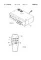
- FIG. 1is a perspective view of a new DIGITAL STORAGE DEVICE FOR A TELEVISION according to the present invention.
- FIG. 2is a rear view of the embodiment of the present invention shown in FIG. 1.
- FIG. 3is a schematic diagram of the present invention.
- FIG. 4is a perspective view of an alternate embodiment of the present invention.
- FIG. 5is a top view of the manual control unit of the present invention.
- FIGS. 1 through 5a new DIGITAL STORAGE DEVICE FOR A TELEVISION embodying the principles and concepts of the present invention and generally designated by the reference numeral 10 will be described.
- the system 10 of the present in inventionincludes a television 12 having a screen 14 and at least one speaker 16.
- the televisionis adapted for transmitting therefrom audio signals and video signals received either by way of an antenna or a coaxial cable.
- the digital storage mechanism 18positioned within the television.
- the digital storage mechanismmay be a stand alone unit 20 equipped with a separate display. Note FIG. 4.
- Both embodimentsinclude an interface logic bus 22 having a plurality of data inputs, a plurality of data outputs, and a plurality of control inputs and outputs. Note FIG. 3. Such control inputs are adapted for allowing the selective transmission of signals from the data inputs to the data outputs thereof as a function of various control signals.
- An audio input line 24 and a video input line 26are connected between the interface logic bus and the television for receiving audio signals and video signals from the television.
- an audio output line 28 and a video output line 30connected between the interface logic bus and the television.
- the output linesserve to transmit audio signals and video signals to the television. It should be noted that in the preferred embodiment, such input and output lines are further connected to a plurality of corresponding jacks 32 situated on a rear of the television. Note FIG. 2. This allows for the use of the present embodiment with a VCR.
- each low pass filter 34Connected between each output line and the interface logic bus and further between each input line and the interface logic bus is a low pass filter 34.
- Each low pass filteris included to ensure that the Nyquist Criterion is met. In other words, the low pass filter should have a 3 dB point at 4.2 Mhz.
- an analog to digital converter 36connected between each input line and the interface logic bus. Such converters are included for converting the signals received from the television from an analog to digital form.
- a digital to analog converter 38is connected between each output line and the interface logic bus for converting the signals transmitted to the television from a digital to analog form.
- an oscillatoris connected thereto. In the preferred embodiment, the sampling frequency is twice the 4.2 Mhz associated with the low pass filter.
- data memory 44connected to the interface logic bus for receiving signals therefrom and storing the same.
- the data memoryis further adapted for transmitting such stored signals to the interface logic bus.
- data memoryhas a large capacity which is capable of storing up to 10 television programs.
- a control logic bus 46is connected to the control inputs and outputs of the interface logic bus for allowing the transfer of control signals to and from the interface logic bus.
- a real time clock 48Connected to the control logic bus is a real time clock 48 for continuously transmitting thereto a current time. It should be understood that such time has associated therewith a current date.
- control memory 50is connected to the control logic bus.
- Such control memoryfunctions to store a plurality of control signals. Each control signal is adapted effect a unique transfer of signals between the inputs and outputs of the interface logic bus thereby implementing a unique function. Such functions will be described in greater detail hereinafter.
- a microprocessor 52For transmitting the control signals from the control memory to the interface logic bus to effect various operations, a microprocessor 52 is connected to the control logic bus.
- the microprocessoris adapted to initialize and control the various components of the digital storage mechanism.
- the microprocessoris adapted to tag each continuous storage of video and audio signals in the data memory with a unique identification number. Each successive program that is stored is assigned a number greater than that assigned to a previously recorded program.
- a digital signal processor 54which is in turn connected to the interface logic bus.
- Such processoris included for implementing real-time video data compression. This is imperative for conserving storage capacity in the data memory.
- a manual control unit 56is provided.
- the control unitis in communication with the microprocessor preferably by means of an infrared transmitter and receiver.
- the manual control unitis included for allowing a user to select a presently executed operation.
- the manual control unitincludes a program button 60, a record memory button 62, an enter button 64, a plurality of numeric buttons 66, and a delete button 68.
- Such methodfirst includes a procedure of recording signals received via the television as a function of time. This procedure including the steps of: pressing the program button, pressing the record memory button for displaying a menu, entering via the numeric buttons a time, date and channel at which recording is desired, and pressing enter.
- the procedure for playing back stored signals received via the televisionincludes the steps of: pressing the program button, pressing the record memory button twice for displaying signals recorded with the associated numeric tag, entering via the numeric buttons a numeral corresponding with the numeric tag associated with the signals desired to be played back, and pressing the enter button.
- a method of deleting stored signals received via the televisionincludes the steps of: pressing the program button, pressing the record memory button twice for displaying signals recorded with associated numeric tag, entering via the numeric buttons a numeral corresponding with the numeric tag associated with the signals desired to be played back, and pressing the delete button.
- the record memory buttonmay be continuously depressed to scroll and highlight various programs listed on the screen of the television. Upon the depression of the delete button, the highlighted program, or stored signals, are deleted.
Landscapes
- Engineering & Computer Science (AREA)
- Multimedia (AREA)
- Signal Processing (AREA)
- Human Computer Interaction (AREA)
- Television Signal Processing For Recording (AREA)
Abstract
Description
Claims (5)
Priority Applications (1)
| Application Number | Priority Date | Filing Date | Title |
|---|---|---|---|
| US08/910,520US5889915A (en) | 1997-08-07 | 1997-08-07 | Digital storage device for a television |
Applications Claiming Priority (1)
| Application Number | Priority Date | Filing Date | Title |
|---|---|---|---|
| US08/910,520US5889915A (en) | 1997-08-07 | 1997-08-07 | Digital storage device for a television |
Publications (1)
| Publication Number | Publication Date |
|---|---|
| US5889915Atrue US5889915A (en) | 1999-03-30 |
Family
ID=25428923
Family Applications (1)
| Application Number | Title | Priority Date | Filing Date |
|---|---|---|---|
| US08/910,520Expired - LifetimeUS5889915A (en) | 1997-08-07 | 1997-08-07 | Digital storage device for a television |
Country Status (1)
| Country | Link |
|---|---|
| US (1) | US5889915A (en) |
Cited By (26)
| Publication number | Priority date | Publication date | Assignee | Title |
|---|---|---|---|---|
| US20010019658A1 (en)* | 1998-07-30 | 2001-09-06 | Barton James M. | Multimedia time warping system |
| US20020037160A1 (en)* | 2000-08-22 | 2002-03-28 | David Locket | Multimedia signal processing system |
| US6508783B2 (en) | 2001-03-14 | 2003-01-21 | Scimed Life Systems, Inc. | Ultrasound method for revascularization and drug delivery |
| US20030026589A1 (en)* | 1998-07-30 | 2003-02-06 | Barton James M. | Smart card digital video recorder system |
| EP1077547A3 (en)* | 1999-08-12 | 2003-09-10 | Pace Micro Technology PLC | System for receiving audio and/or video data and for selecting and storing this audio and/or video data |
| US20040013406A1 (en)* | 1998-07-30 | 2004-01-22 | Barton James M. | Digital video recorder system with an integrated DVD recording device |
| US20040091235A1 (en)* | 2002-11-07 | 2004-05-13 | Srinivas Gutta | Tracking of partially viewed shows so that they can be marked for deletion when a personal video recorder runs out of space |
| KR20050008390A (en)* | 2003-07-15 | 2005-01-21 | 삼성전자주식회사 | A television capable of storing audio signal and a controlling method thereof |
| US20050063674A1 (en)* | 2002-11-18 | 2005-03-24 | Kryzysztof Bilinski | Processor for safe processing of audio/video data and method of protecting audio/video data in audio/video data processor |
| US20070009235A1 (en)* | 2005-07-07 | 2007-01-11 | Eric Walters | System and method for digital content retrieval |
| US7272298B1 (en) | 1998-05-06 | 2007-09-18 | Burst.Com, Inc. | System and method for time-shifted program viewing |
| US20070230921A1 (en)* | 2001-04-05 | 2007-10-04 | Barton James M | Multimedia time warping system |
| US20090129747A1 (en)* | 2007-11-20 | 2009-05-21 | Echostar Technologies Corporation | Methods and Apparatus for Displaying Information Regarding Interstitials of a Video Stream |
| US20090238536A1 (en)* | 2008-03-20 | 2009-09-24 | Dish Network L.L.C. | Method and apparatus for replacement of audio data in recorded audio/video stream |
| US20090300699A1 (en)* | 2008-05-30 | 2009-12-03 | Echostar Technologies L.L.C. | Methods and apparatus for presenting substitute content in an audio/video stream using text data |
| US20090307741A1 (en)* | 2008-06-09 | 2009-12-10 | Echostar Technologies L.L.C. | Methods and apparatus for dividing an audio/video stream into multiple segments using text data |
| US20100158484A1 (en)* | 2008-12-24 | 2010-06-24 | EchoStar Technologies, L.L.C. | Methods and apparatus for filtering and inserting content into a presentation stream using signature data |
| US20100162291A1 (en)* | 2008-12-24 | 2010-06-24 | EchoStar Technologies, L.L.C. | Methods and apparatus for filtering content from a presentation stream using signature data |
| US20100162344A1 (en)* | 2008-12-24 | 2010-06-24 | EchoStar Technologies, L.L.C. | Methods and apparatus for identifying segments of content in a presentation stream using signature data |
| US20100322592A1 (en)* | 2009-06-17 | 2010-12-23 | EchoStar Technologies, L.L.C. | Method and apparatus for modifying the presentation of content |
| US20110197224A1 (en)* | 2010-02-09 | 2011-08-11 | Echostar Global B.V. | Methods and Apparatus For Selecting Advertisements For Output By A Television Receiver Based on Social Network Profile Data |
| US8136140B2 (en) | 2007-11-20 | 2012-03-13 | Dish Network L.L.C. | Methods and apparatus for generating metadata utilized to filter content from a video stream using text data |
| US8165450B2 (en) | 2007-11-19 | 2012-04-24 | Echostar Technologies L.L.C. | Methods and apparatus for filtering content in a video stream using text data |
| US8934758B2 (en) | 2010-02-09 | 2015-01-13 | Echostar Global B.V. | Methods and apparatus for presenting supplemental content in association with recorded content |
| US9967534B1 (en) | 2004-11-19 | 2018-05-08 | Tivo Solutions Inc. | Digital video recorder video editing system |
| US11172269B2 (en) | 2020-03-04 | 2021-11-09 | Dish Network L.L.C. | Automated commercial content shifting in a video streaming system |
Citations (12)
| Publication number | Priority date | Publication date | Assignee | Title |
|---|---|---|---|---|
| US4488179A (en)* | 1980-09-27 | 1984-12-11 | Robert Bosch Gmbh | Television viewing center system |
| US4963995A (en)* | 1988-12-27 | 1990-10-16 | Explore Technology, Inc. | Audio/video transceiver apparatus including compression means |
| US5083212A (en)* | 1987-04-14 | 1992-01-21 | Sony Corporation | Apparatus and method for recording a color television signal on an optical disc |
| US5121476A (en)* | 1988-02-22 | 1992-06-09 | Yee Keen Y | TV data capture device |
| US5142375A (en)* | 1988-09-27 | 1992-08-25 | Sony Corporation | Video camera integral with magnetic recording and reproducing device, and with color video signal processing apparatus |
| US5153726A (en)* | 1986-12-30 | 1992-10-06 | Questech Limited | Recording and editing of moving television pictures |
| US5319501A (en)* | 1990-08-17 | 1994-06-07 | Mitsubishi Denki Kabushiki Kaisha | Magnetic recording and reproducing apparatus which records analog time-base-compressed audio signals along with video signals |
| US5359365A (en)* | 1991-05-24 | 1994-10-25 | Canon Kabushiki Kaisha | Moving image processing method and apparatus |
| US5430579A (en)* | 1989-05-09 | 1995-07-04 | Mitsubishi Denki Kabushiki Kaisha | Apparatus for digitally recording analog video signals in ordinary and long mode |
| US5555097A (en)* | 1993-05-18 | 1996-09-10 | Goldstar Co., Ltd. | Television-integrated video cassette recorder apparatus |
| US5565929A (en)* | 1992-10-13 | 1996-10-15 | Sony Corporation | Audio-visual control apparatus for determining a connection of appliances and controlling functions of appliances |
| US5798800A (en)* | 1994-03-19 | 1998-08-25 | Sony Corporation | Apparatus for controlling a switcher and a special effects device |
- 1997
- 1997-08-07USUS08/910,520patent/US5889915A/ennot_activeExpired - Lifetime
Patent Citations (12)
| Publication number | Priority date | Publication date | Assignee | Title |
|---|---|---|---|---|
| US4488179A (en)* | 1980-09-27 | 1984-12-11 | Robert Bosch Gmbh | Television viewing center system |
| US5153726A (en)* | 1986-12-30 | 1992-10-06 | Questech Limited | Recording and editing of moving television pictures |
| US5083212A (en)* | 1987-04-14 | 1992-01-21 | Sony Corporation | Apparatus and method for recording a color television signal on an optical disc |
| US5121476A (en)* | 1988-02-22 | 1992-06-09 | Yee Keen Y | TV data capture device |
| US5142375A (en)* | 1988-09-27 | 1992-08-25 | Sony Corporation | Video camera integral with magnetic recording and reproducing device, and with color video signal processing apparatus |
| US4963995A (en)* | 1988-12-27 | 1990-10-16 | Explore Technology, Inc. | Audio/video transceiver apparatus including compression means |
| US5430579A (en)* | 1989-05-09 | 1995-07-04 | Mitsubishi Denki Kabushiki Kaisha | Apparatus for digitally recording analog video signals in ordinary and long mode |
| US5319501A (en)* | 1990-08-17 | 1994-06-07 | Mitsubishi Denki Kabushiki Kaisha | Magnetic recording and reproducing apparatus which records analog time-base-compressed audio signals along with video signals |
| US5359365A (en)* | 1991-05-24 | 1994-10-25 | Canon Kabushiki Kaisha | Moving image processing method and apparatus |
| US5565929A (en)* | 1992-10-13 | 1996-10-15 | Sony Corporation | Audio-visual control apparatus for determining a connection of appliances and controlling functions of appliances |
| US5555097A (en)* | 1993-05-18 | 1996-09-10 | Goldstar Co., Ltd. | Television-integrated video cassette recorder apparatus |
| US5798800A (en)* | 1994-03-19 | 1998-08-25 | Sony Corporation | Apparatus for controlling a switcher and a special effects device |
Cited By (70)
| Publication number | Priority date | Publication date | Assignee | Title |
|---|---|---|---|---|
| US7272298B1 (en) | 1998-05-06 | 2007-09-18 | Burst.Com, Inc. | System and method for time-shifted program viewing |
| US8380049B2 (en) | 1998-05-06 | 2013-02-19 | Tivo Inc. | Playback of audio/video content with control codes |
| US9094724B2 (en) | 1998-05-06 | 2015-07-28 | Tivo Inc. | Multi-channel playback of audio/video content |
| US9113212B2 (en) | 1998-05-06 | 2015-08-18 | Tivo Inc. | Simultaneous recording and playback of audio/video programs |
| US9300902B2 (en) | 1998-05-06 | 2016-03-29 | Tivo Inc. | Playback of audio/video content with control codes |
| US9344668B2 (en) | 1998-05-06 | 2016-05-17 | Tivo Inc. | System and method for time-shifted program viewing |
| US9350934B2 (en) | 1998-05-06 | 2016-05-24 | Tivo Inc. | System and method for time-shifted program viewing |
| US9467749B2 (en) | 1998-05-06 | 2016-10-11 | Tivo Inc. | Playback of audio/video content with control codes |
| US20080089671A1 (en)* | 1998-05-06 | 2008-04-17 | Lang Richard A | Simultaneous Recording and Playback of Audio/Video Programs |
| USRE43325E1 (en) | 1998-05-06 | 2012-04-24 | Tivo Inc. | System and method for time-shifted program viewing |
| US20080075426A1 (en)* | 1998-05-06 | 2008-03-27 | Lang Richard A | Playback of Audio/Video Content with Control Codes |
| US20080069519A1 (en)* | 1998-05-06 | 2008-03-20 | Lang Richard A | Multi-Channel Playback of Audio/Video Content |
| US8538241B2 (en) | 1998-07-30 | 2013-09-17 | Tivo Inc. | Multimedia signal processing system |
| US20090208185A1 (en)* | 1998-07-30 | 2009-08-20 | Tivo Inc. | Multiple output digital video recording system |
| US20010019658A1 (en)* | 1998-07-30 | 2001-09-06 | Barton James M. | Multimedia time warping system |
| US8824865B2 (en) | 1998-07-30 | 2014-09-02 | Tivo Inc. | Digital video recorder system with an integrated DVD recording device |
| US8380041B2 (en) | 1998-07-30 | 2013-02-19 | Tivo Inc. | Transportable digital video recorder system |
| US20050132418A1 (en)* | 1998-07-30 | 2005-06-16 | Tivo Inc. | Multimedia time warping system |
| US8526781B2 (en) | 1998-07-30 | 2013-09-03 | Tivo Inc. | Multiple output digital video recording system |
| US8577205B2 (en) | 1998-07-30 | 2013-11-05 | Tivo Inc. | Digital video recording system |
| US20080288998A1 (en)* | 1998-07-30 | 2008-11-20 | David Locket | Multimedia signal processing system |
| US7529465B2 (en) | 1998-07-30 | 2009-05-05 | Tivo Inc. | System for time shifting multimedia content streams |
| US8457476B2 (en) | 1998-07-30 | 2013-06-04 | Tivo Inc. | Multimedia signal processing system |
| US20090136215A1 (en)* | 1998-07-30 | 2009-05-28 | Barton James M | Digital video recorder system with an integrated dvd recording device |
| US9002173B2 (en) | 1998-07-30 | 2015-04-07 | Tivo Inc. | Digital security surveillance system |
| US20070166001A1 (en)* | 1998-07-30 | 2007-07-19 | Barton James M | Digital security surveillance system |
| US8965173B2 (en) | 1998-07-30 | 2015-02-24 | Tivo Inc. | Multimedia stream processing system |
| US20090269024A1 (en)* | 1998-07-30 | 2009-10-29 | Tivo Inc. | Multimedia signal processing system |
| US20020146233A1 (en)* | 1998-07-30 | 2002-10-10 | Barton James M. | Multimedia time warping system |
| US20040013406A1 (en)* | 1998-07-30 | 2004-01-22 | Barton James M. | Digital video recorder system with an integrated DVD recording device |
| US7668435B2 (en) | 1998-07-30 | 2010-02-23 | Tivo Inc. | Multimedia signal processing system |
| US20030026589A1 (en)* | 1998-07-30 | 2003-02-06 | Barton James M. | Smart card digital video recorder system |
| EP1077547A3 (en)* | 1999-08-12 | 2003-09-10 | Pace Micro Technology PLC | System for receiving audio and/or video data and for selecting and storing this audio and/or video data |
| US7558472B2 (en) | 2000-08-22 | 2009-07-07 | Tivo Inc. | Multimedia signal processing system |
| US20020037160A1 (en)* | 2000-08-22 | 2002-03-28 | David Locket | Multimedia signal processing system |
| US6508783B2 (en) | 2001-03-14 | 2003-01-21 | Scimed Life Systems, Inc. | Ultrasound method for revascularization and drug delivery |
| US6702775B2 (en) | 2001-03-14 | 2004-03-09 | Scimed Life Systems, Inc. | Ultrasound method for revascularization and drug delivery |
| US20070230921A1 (en)* | 2001-04-05 | 2007-10-04 | Barton James M | Multimedia time warping system |
| US7260309B2 (en) | 2002-11-07 | 2007-08-21 | Koninklijke Philips Electronics N.V. | Tracking of partially viewed shows so that they can be marked for deletion when a personal video recorder runs out of space |
| US20040091235A1 (en)* | 2002-11-07 | 2004-05-13 | Srinivas Gutta | Tracking of partially viewed shows so that they can be marked for deletion when a personal video recorder runs out of space |
| US20050063674A1 (en)* | 2002-11-18 | 2005-03-24 | Kryzysztof Bilinski | Processor for safe processing of audio/video data and method of protecting audio/video data in audio/video data processor |
| KR20050008390A (en)* | 2003-07-15 | 2005-01-21 | 삼성전자주식회사 | A television capable of storing audio signal and a controlling method thereof |
| US9967534B1 (en) | 2004-11-19 | 2018-05-08 | Tivo Solutions Inc. | Digital video recorder video editing system |
| US20070009235A1 (en)* | 2005-07-07 | 2007-01-11 | Eric Walters | System and method for digital content retrieval |
| US8139924B2 (en) | 2005-07-07 | 2012-03-20 | Tivo Inc. | System and method for digital content retrieval |
| US8687949B2 (en) | 2005-07-07 | 2014-04-01 | Tivo Inc. | System and method for digital content retrieval |
| US8977106B2 (en) | 2007-11-19 | 2015-03-10 | Echostar Technologies L.L.C. | Methods and apparatus for filtering content in a video stream using closed captioning data |
| US8165450B2 (en) | 2007-11-19 | 2012-04-24 | Echostar Technologies L.L.C. | Methods and apparatus for filtering content in a video stream using text data |
| US8136140B2 (en) | 2007-11-20 | 2012-03-13 | Dish Network L.L.C. | Methods and apparatus for generating metadata utilized to filter content from a video stream using text data |
| US8965177B2 (en) | 2007-11-20 | 2015-02-24 | Echostar Technologies L.L.C. | Methods and apparatus for displaying interstitial breaks in a progress bar of a video stream |
| US20090129747A1 (en)* | 2007-11-20 | 2009-05-21 | Echostar Technologies Corporation | Methods and Apparatus for Displaying Information Regarding Interstitials of a Video Stream |
| US8165451B2 (en) | 2007-11-20 | 2012-04-24 | Echostar Technologies L.L.C. | Methods and apparatus for displaying information regarding interstitials of a video stream |
| US8606085B2 (en) | 2008-03-20 | 2013-12-10 | Dish Network L.L.C. | Method and apparatus for replacement of audio data in recorded audio/video stream |
| US20090238536A1 (en)* | 2008-03-20 | 2009-09-24 | Dish Network L.L.C. | Method and apparatus for replacement of audio data in recorded audio/video stream |
| US8726309B2 (en) | 2008-05-30 | 2014-05-13 | Echostar Technologies L.L.C. | Methods and apparatus for presenting substitute content in an audio/video stream using text data |
| US8156520B2 (en) | 2008-05-30 | 2012-04-10 | EchoStar Technologies, L.L.C. | Methods and apparatus for presenting substitute content in an audio/video stream using text data |
| US20090300699A1 (en)* | 2008-05-30 | 2009-12-03 | Echostar Technologies L.L.C. | Methods and apparatus for presenting substitute content in an audio/video stream using text data |
| US9357260B2 (en) | 2008-05-30 | 2016-05-31 | Echostar Technologies L.L.C. | Methods and apparatus for presenting substitute content in an audio/video stream using text data |
| US20090307741A1 (en)* | 2008-06-09 | 2009-12-10 | Echostar Technologies L.L.C. | Methods and apparatus for dividing an audio/video stream into multiple segments using text data |
| US8510771B2 (en) | 2008-12-24 | 2013-08-13 | Echostar Technologies L.L.C. | Methods and apparatus for filtering content from a presentation stream using signature data |
| US8588579B2 (en) | 2008-12-24 | 2013-11-19 | Echostar Technologies L.L.C. | Methods and apparatus for filtering and inserting content into a presentation stream using signature data |
| US8407735B2 (en) | 2008-12-24 | 2013-03-26 | Echostar Technologies L.L.C. | Methods and apparatus for identifying segments of content in a presentation stream using signature data |
| US20100162344A1 (en)* | 2008-12-24 | 2010-06-24 | EchoStar Technologies, L.L.C. | Methods and apparatus for identifying segments of content in a presentation stream using signature data |
| US20100162291A1 (en)* | 2008-12-24 | 2010-06-24 | EchoStar Technologies, L.L.C. | Methods and apparatus for filtering content from a presentation stream using signature data |
| US20100158484A1 (en)* | 2008-12-24 | 2010-06-24 | EchoStar Technologies, L.L.C. | Methods and apparatus for filtering and inserting content into a presentation stream using signature data |
| US8437617B2 (en) | 2009-06-17 | 2013-05-07 | Echostar Technologies L.L.C. | Method and apparatus for modifying the presentation of content |
| US20100322592A1 (en)* | 2009-06-17 | 2010-12-23 | EchoStar Technologies, L.L.C. | Method and apparatus for modifying the presentation of content |
| US20110197224A1 (en)* | 2010-02-09 | 2011-08-11 | Echostar Global B.V. | Methods and Apparatus For Selecting Advertisements For Output By A Television Receiver Based on Social Network Profile Data |
| US8934758B2 (en) | 2010-02-09 | 2015-01-13 | Echostar Global B.V. | Methods and apparatus for presenting supplemental content in association with recorded content |
| US11172269B2 (en) | 2020-03-04 | 2021-11-09 | Dish Network L.L.C. | Automated commercial content shifting in a video streaming system |
Similar Documents
| Publication | Publication Date | Title |
|---|---|---|
| US5889915A (en) | Digital storage device for a television | |
| EP1158791B9 (en) | Broadcast receiver, broadcast control method, and computer readable recording medium | |
| JPH0323748Y2 (en) | ||
| EP0401930A3 (en) | An interface for a tv-vcr system | |
| KR920020451A (en) | Video cassette recorder with recording signal storage function | |
| US7818766B2 (en) | Last channel button functionality | |
| JP4493254B2 (en) | Digital broadcast receiving apparatus having EPG screen display function | |
| US20020114613A1 (en) | Audio/video editing in digital network recorders | |
| JP4208434B2 (en) | Broadcast receiver, broadcast control method, computer-readable recording medium, and computer program | |
| US9917703B2 (en) | Portable control device for controlling playback streams in distributed system | |
| JP2844593B2 (en) | Receiver | |
| JP4342081B2 (en) | Program storage device and program storage method | |
| KR930008597A (en) | Computer mouse and microphone device and its use | |
| JP2000112489A (en) | Voice input remote control system | |
| EP1353328B1 (en) | Recording medium player apparatus | |
| US20020184039A1 (en) | Radio content browser | |
| US7536502B2 (en) | Controller device to be connected to IEEE 1394 serial bus | |
| KR100392683B1 (en) | How to record V-thier reservation using personal computer | |
| KR100370003B1 (en) | apparatus and method for reservation recording in TV | |
| KR19980025457A (en) | Broadcast signal recording and reproducing apparatus and method of broadcast receiver | |
| KR200225337Y1 (en) | Television with delayed viewing | |
| KR910001777B1 (en) | Key operation guidance method and circuit by voice | |
| JPH1092162A (en) | Display apparatus | |
| US20070098358A1 (en) | Digital video recorder with jump-pause function | |
| KR19990060497A (en) | Multifunction TV system |
Legal Events
| Date | Code | Title | Description |
|---|---|---|---|
| STCF | Information on status: patent grant | Free format text:PATENTED CASE | |
| REMI | Maintenance fee reminder mailed | ||
| REIN | Reinstatement after maintenance fee payment confirmed | ||
| FP | Lapsed due to failure to pay maintenance fee | Effective date:20030330 | |
| FEPP | Fee payment procedure | Free format text:PETITION RELATED TO MAINTENANCE FEES FILED (ORIGINAL EVENT CODE: PMFP); ENTITY STATUS OF PATENT OWNER: LARGE ENTITY | |
| FEPP | Fee payment procedure | Free format text:PETITION RELATED TO MAINTENANCE FEES GRANTED (ORIGINAL EVENT CODE: PMFG); ENTITY STATUS OF PATENT OWNER: LARGE ENTITY | |
| FPAY | Fee payment | Year of fee payment:4 | |
| SULP | Surcharge for late payment | ||
| PRDP | Patent reinstated due to the acceptance of a late maintenance fee | Effective date:20040405 | |
| FEPP | Fee payment procedure | Free format text:PAYOR NUMBER ASSIGNED (ORIGINAL EVENT CODE: ASPN); ENTITY STATUS OF PATENT OWNER: LARGE ENTITY | |
| FEPP | Fee payment procedure | Free format text:PAT HOLDER NO LONGER CLAIMS SMALL ENTITY STATUS, ENTITY STATUS SET TO UNDISCOUNTED (ORIGINAL EVENT CODE: STOL); ENTITY STATUS OF PATENT OWNER: LARGE ENTITY | |
| AS | Assignment | Owner name:SAMSUNG ELECTRONICS CO., LTD., KOREA, REPUBLIC OF Free format text:ASSIGNMENT OF ASSIGNORS INTEREST;ASSIGNOR:HEWTON, ALFRED F.;REEL/FRAME:017527/0387 Effective date:20060411 | |
| FPAY | Fee payment | Year of fee payment:8 | |
| FPAY | Fee payment | Year of fee payment:12 |