US5889524A - Reconstruction of three-dimensional objects using labeled piecewise smooth subdivision surfaces - Google Patents
Reconstruction of three-dimensional objects using labeled piecewise smooth subdivision surfacesDownload PDFInfo
- Publication number
- US5889524A US5889524AUS08/709,577US70957796AUS5889524AUS 5889524 AUS5889524 AUS 5889524AUS 70957796 AUS70957796 AUS 70957796AUS 5889524 AUS5889524 AUS 5889524A
- Authority
- US
- United States
- Prior art keywords
- embedded
- mesh
- data
- abstract
- feature
- Prior art date
- Legal status (The legal status is an assumption and is not a legal conclusion. Google has not performed a legal analysis and makes no representation as to the accuracy of the status listed.)
- Expired - Lifetime
Links
Images


Classifications
- G—PHYSICS
- G06—COMPUTING OR CALCULATING; COUNTING
- G06T—IMAGE DATA PROCESSING OR GENERATION, IN GENERAL
- G06T17/00—Three dimensional [3D] modelling, e.g. data description of 3D objects
- G06T17/20—Finite element generation, e.g. wire-frame surface description, tesselation
Definitions
- This inventiongenerally relates to a method for imaging and modeling an object in three dimensions, and more specifically, to a method for using data representing a three-dimensional model of the object to reconstruct its surface.
- Reconstructing the surface of a three-dimensional objectcan provide information useful for a variety of applications such as generating computer aided design models from physical objects, or outlining biological structures or organs. From the reconstructions, a variety of measurements can be made of the object's dimensions and shape, for example, for use in product development or in scientific investigation. Alternatively, the reconstructions can be used to guide the manufacturing of facsimiles of the object.
- Implicit reconstruction methodsattempt to find a smooth function whose value approaches zero when the reconstructed surface fits the input data points most closely. These methods differ in the form of the function, and in the measure of closeness of fit. The disadvantage of this approach is the risk that spurious surface components not supported by the data may be generated.
- a second type of reconstruction algorithmuses parametric techniques. Parametric reconstruction techniques represent a reconstructed surface as a topological embedding function of a two-dimensional parameter domain into a three-dimensional surface. Previous work has concentrated on domain spaces with simple topology, e.g., the plane and the sphere. This simplification of the problem may have the disadvantage of constraining shapes into variants of a geometric figure, making it difficult to fit a modeled surface to more complex shapes.
- reconstruction algorithmsare generally developed to address specific problems. They make use of, and hence assume, a partial structure in the data. For example, algorithms that reconstruct a surface from contours generated by slicing the object and stacking the outlines of the object from the slices depend on the fact that the data are organized into closed polygons lying in parallel planes. Attempting to reconstruct a surface without prior assumptions regarding the spatial relationships of the data points derived from that surface has a practical advantage in that the algorithm employed is general purpose and widely applicable.
- the heartis a complex three-dimensional organ normally having four chambers and four valves. Disease processes can affect any number of these chambers and valves, altering their structure and/or function. Measuring the size, shape, and function of the chambers and valves provides useful information that can assist a physician in evaluating the effect of disease processes, hemodynamic changes, and other influences on the heart. Such measurements may help in diagnosing cardiac problems in patients, evaluating the effect of treatment, assessing prognosis, and in understanding the underlying mechanisms of the disease process and its response to therapeutic interventions.
- the left ventricle of the heartis investigated.
- the left ventricleis of greatest importance to health, because it pumps blood through the body.
- the right ventricleis also studied, because it provides the impetus for blood circulation through the lungs.
- One of the most commonly used parameters for diagnostic purposesis the ventricular chamber volume. Patients with diseased hearts may have an enlarged left ventricle, particularly at advanced stages of the disease.
- the most commonly used parameter of heart functionis the ejection fraction, which expresses the proportion of chamber volume ejected with each heart beat, and by reconstructing the surface of the heart, this parameter can more readily be determined.
- the reconstructed surface of the heartcan also be used for the purpose of monitoring certain parameters indicative of the function of the left ventricle of the heart. These parameters may be used in evaluating a patient's condition during surgical procedures. Other important parameters include the range of motion of the left ventricular wall and the thickening of the ventricular wall, both of which are indicators of coronary heart disease, and of other disease entities.
- the shape of the ventricleprovides information regarding its status, as the left ventricle becomes more spherical under certain loading conditions. These parameters also provide information that can be used to detect coronary heart disease and other medical problems of the heart. All of these parameters--volume, shape, ejection fraction, wall motion, and wall thickening, rely on having an accurate representation of the ventricular surface.
- the effects of coronary heart diseaseare regional, being limited to the portion of the heart muscle receiving blood supply from an affected artery.
- the internal diameter of an arteryis reduced by atherosclerotic plaque, blood flow to the specific region of the heart supplied by that artery is restricted.
- some degree of dysfunctionoccurs in the affected heart muscle.
- the affected muscledies and is replaced by scar tissue, which is non-contractile.
- the progress of coronary artery diseaseis revealed by its effect on regional left ventricular function, and the severity of a heart attack is measured by the size of the dysfunctional region and by the extent of the dysfunction.
- any improvement of regional function in the affected portion of the left ventricleis an indication of the effectiveness of a prescribed treatment.
- the appearance of dysfunction in a previously well-functioning ventricleis a serious warning that the blood supply is insufficient. Should a deterioration of function occur during surgery, it may be construed as an indication that the anesthesiologist should increase the fluid volume and/or engage in other corrective measures.
- the detection of regional dysfunctionhas also been used during stress studies, wherein a patient's heart is imaged using ultrasound while at rest and after exercise, to determine whether the patient's arteries, which may have been open sufficiently while at rest, provide inadequate blood flow during exercise.
- the degree of dysfunction after a heart attack has occurredmay also be determined to develop a prognosis. For example, patients with serious residual dysfunction after a heart attack are at a higher risk of dying in the first year, and more aggressive treatment may be indicated.
- the mitral valvecontrols the flow of blood entering the left ventricle.
- the leaflets of the mitral valvemay become distorted in size, becoming larger and more redundant.
- the shape of the leafletsmay also vary, particularly when the leaflet size is increased, or when the structures that help to tether the leaflets in their proper position become misaligned, ruptured, or stretched. Variations in leaflet size or shape may affect the ability of the valve to open or close properly.
- a method that references specific regions of the surface reconstruction to the corresponding input point data so as to provide a specific identification of those regions, and which is generally independent of the size and shape of the object,should improve the applicability of the reconstruction for various applications.
- the ability to identify certain anatomic features on the reconstruction of its surfaceis useful in analyzing parameters of cardiac function such as wall motion and wall thickening in the region that may be abnormal due to a disease process.
- a method that references specific regions of the heart to a standard or average cardiac template so as to identify an affected region of a patient's heart (even if abnormal due to disease)should aid in better assessing problems that are diagnosed.
- a methodfor generating a surface reconstruction of an object.
- a specific application of this methodis to reconstruct the surface of the heart.
- the methodincludes the step of first imaging the heart to produce imaging data.
- the contours of the left ventricle or of some other structure of interest, and of related anatomic landmarks or featuresare delineated and recorded in the form of x, y, and z coordinates.
- the coordinates for each landmark and for the left ventricleconstitute an input point data set for that structure.
- An abstract control meshis generated, which is designed to fit the left ventricle for any of a variety or wide range of normal and diseased hearts.
- the abstract control meshcontains a plurality of abstract features, each consisting of a set of vertices, edges, and/or faces corresponding to an anatomic landmark on the object.
- anatomic landmarks for the left ventriclemight include the mitral annulus, which is defined as a set of edges, the apex, which is defined as a point, and the septum, which is defined as a set of contiguous faces.
- the abstract vertices, edges, and facesare labeled according to their location relative to various abstract features, providing means for identifying locations on the object, e.g., on the left ventricle.
- an embedded control meshis produced by assigning three-dimensional locations to each vertex of the abstract control mesh, and an embedded subdivided mesh is produced by recursive subdivision of the embedded control mesh.
- the vertices on the abstract control meshare initially manually assigned x, y, and z coordinates that yield an embedded subdivided mesh with a generally ventricular shape, for example, by using a computer assisted drawing (CAD) program, producing a shaped model.
- CADcomputer assisted drawing
- the shaped modelis rigidly aligned to the input point data sets, yielding an aligned embedded mesh.
- the methodfurther comprises the step of iteratively adjusting the location of the embedded control mesh vertices to improve the fit of the faces of the subdivided mesh to the input point data sets.
- the adjustmentcontinues until the change in the value of the loss function and the changes in the locations of the vertices of the embedded control mesh satisfy a standard convergence test. For practical purposes, an upper bound is placed on the number of iterations.
- the loss functionincludes a residual energy, which is a measure of both the distance from points in the input data set to the nearest faces in the corresponding abstract feature, and a smoothness penalty.
- a parameter called "tension"controls a relative weight of the smoothness penalty versus the residual energy terms of the loss function.
- Another aspect of the present inventionis directed to a method for reconstructing anatomical features of the heart, such as the endocardial surface of the right ventricle, the epicardial surface of either ventricle, any of the leaflets of the mitral valve, or any surface of the heart, or any other object.
- This methodincludes steps that are generally consistent with the steps of the method described above.
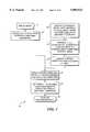
- FIG. 1is a top level or overview flow chart that generally defines the steps of the method for reconstructing the left ventricular surface using data from randomly oriented image planes and anatomic landmarks;
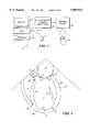
- FIG. 2is a schematic block diagram of a system in accordance with the present invention that is used for imaging the heart of a patient, and analyzing the images to determine cardiac parameters;
- FIG. 3Ais a schematic view of a heart and a portion of an esophagus, illustrating how a transesophageal ultrasonic probe is used to image the heart;
- FIG. 3Bis a graphic representation of one of the image planes produced by the transesophageal ultrasonic probe
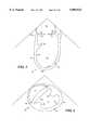
- FIG. 4illustrates a schematic cross-sectional view of a portion of the heart imaged along its longitudinal axis, through the left ventricle, and indicating the anatomic landmarks associated with the left ventricle;
- FIG. 5is a schematic cross-sectional view of the heart imaged along its longitudinal axis, in a different plane from FIG. 3, indicating additional anatomic landmarks;
- FIG. 6is a schematic cross-sectional view of the left ventricle, imaged along a transverse axis, with associated anatomic landmarks;
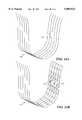
- FIGS. 7A and 7Bschematically illustrate the cross-sectional image planes that are in parallel with the transverse axis of the heart and those that are orthogonal thereto, in parallel with the longitudinal axis, as produced by a magnetic resonance imaging system;
- FIGS. 8A and 8Brespectively illustrate angled cross-sectional image planes obtained with an ultrasonic probe from two different imaging positions, and the rotational cross-sectional image planes obtained with an ultrasonic probe manipulated in a fixed position;
- FIG. 9illustrates the angled and rotational cross-sectional image planes obtained with a transcutaneous ultrasonic probe positioned in the parasternal and apical acoustic windows
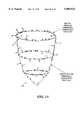
- FIG. 10illustrates one abstract control mesh for the left ventricle with labeled faces to indicate their association with anatomic landmarks
- FIG. 11illustrates part of an abstract control mesh for the left ventricle in which the outflow track is assigned additional triangles
- FIG. 12illustrates the subdivision of triangles comprising the abstract control mesh into smaller triangles
- FIG. 13A and 13Bschematically illustrate how triangles corresponding to a feature are fitted to the x, y, and z coordinates of the traced borders for the corresponding anatomic landmark;
- FIGS. 14A and 14Bschematically illustrate how the surface would be unduly influenced by small perturbations in the input data points if there were no smoothness penalty term in the loss function
- FIG. 15schematically illustrates how a residual energy term in a loss function is applied in fitting the abstract control mesh to the data, taking into account the correspondence between the data and surface features;
- FIG. 16is a flow chart illustrating the logical steps employed in tracing a border from a displayed image of a portion of the heart
- FIG. 17is a flow chart that identifies the steps used to generate an abstract control mesh of the left ventricle
- FIG. 18is a flow chart that shows the steps followed to rigidly align an initial embedded subdivided mesh with anatomic landmarks of input data
- FIG. 19is a flow chart illustrating the steps in subdividing the abstract control mesh.
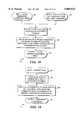
- FIG. 20is a flow chart that identifies the steps used to fit the embedded subdivided mesh to points on the input data.
- the present inventioncan readily be applied to reconstructing the surface of any three-dimensional object, has application in many different areas of technology, and thus is not limited only to medical applications.
- the bodies of a population of different individualscan be scanned to produce three-dimensional image data, and the present method can be applied to reconstruct the surfaces of the bodies.
- the reconstructed body surfacescan be used to more accurately determine a range of dimensions such as collar size and sleeve length.
- the present inventionwas developed to reconstruct a surface of an object using image data that are relatively sparse and noisy, such as the data produced by imaging an organ, it is helpful to illustrate the present invention by applying it to reconstruct the surface of a left ventricle in a patient's heart.
- FIG. 1includes a top level or overview flow chart 10 that generally defines the steps of the method used in the present invention for reconstructing the left ventricular surface.
- the methodemploys data derived from randomly oriented image planes and anatomic landmarks.
- the data for a heartare acquired by imaging the heart in multiple planes whose location and orientation in three-dimensional space are known.
- the borders of the left ventricle and other anatomic structures, features, or landmarksare traced at end diastole and end systole in a block 14, producing an input data set that includes points representing the locations of the anatomic landmarks.
- an abstract modelis generated in a block 16.
- the abstract modelincludes abstract faces, edges, and/or vertices labeled according to their location relative to the anatomic landmarks.
- X, y, and z coordinatesare manually assigned to the vertices of the abstract model in a block 18, to produce an initial embedded control mesh.
- the data for a plurality of heartsare averaged to produce the x, y, and z coordinates for the vertices of the abstract model.
- the initial embedded control meshis subdivided N times in a block 20. In the preferred embodiment, the value of N is equal to 2. This step produces an embedded subdivided mesh, which is then applied to the data for an individual's heart.
- the embedded subdivided meshis rigidly aligned to the input data set defining the traced borders and location of the anatomic landmarks, which was produced in block 14.
- the vertices of the embedded subdivided meshare then adjusted to optimize the fit of the aligned subdivided control mesh to the input data in a block 24. This last step yields the reconstructed surface, as indicated in a block 26
- FIG. 2A cardiac imaging and model processing system 30 that is used to produce the images that are traced to define the left ventricle and anatomic landmarks (in block 14 of FIG. 1) is disclosed in FIG. 2.
- This systemincludes a central processing unit (CPU) 32 that is typically part of a personal computer or graphic workstation terminal, and which is coupled to a graphics display 34 and to a keyboard 36 for input of data or instructions controlling the image processing and modeling procedures used to reconstruct a surface of a patient's heart in accordance with the present invention.
- a mouse 38(or other pointing device) is coupled to CPU 32 for use in graphically controlling software running on CPU 32, for example, by selection of menu items, or for manually tracing images produced on graphics display 34, as explained below.
- CPU 32is coupled through an appropriate input card or port (neither shown) to an analog-to-digital converter (ADC) and image processor 40.
- ADC and image processor 40receives an analog signal produced by an imaging device 42, converts the analog signal to a digital signal, and processes the digital signal to a form appropriate for input to CPU 32 and display on graphics display 34.
- ADC and image processor 40controls the imaging device as it scans a heart 44 beating inside a patient (not shown). Details of the processing are not included, since they depend on the type of imaging device used and are well known in the art.
- imaging device 42may comprise an ultrasound probe, a magnetic resonance imaging system, or a cine CT imaging system, all of which are well known to those of ordinary skill in this art.
- each of these types of imaging devicescould provide the analog signal used to create an image of heart 44 on graphics display 34, the current preferred form of cardiac imaging and model processing system 30 uses ultrasound for imaging heart 44.
- a transesophageal ultrasonic probe 50is the preferred form of imaging device 42. This probe is schematically illustrated in a position adjacent heart 44, where it has been inserted through a patient's esophagus 48.
- the transesophageal ultrasonic probeis coupled to ADC and image processor 40 (shown in FIG. 2) through a cable 52, which extends upwardly through the esophagus and out of the patient's mouth (not shown).
- transesophageal ultrasonic probe 50is positioned to scan a left ventricle 46 of the heart.
- the preferred embodiment of the present inventionis disclosed by way of example, in connection with reconstructing the surface of left ventricle 46, it is equally applicable and useful in reconstructing the surfaces of other portions of the heart so that parameters indicative of the condition of the patient's heart can be evaluated, as discussed above.
- the determination of cardiac parameters in relation to the anatomical landmarks of the heartis applicable to portions of the heart that vary significantly from patient to patient, both in size and shape.
- transesophageal ultrasonic probe 50has been developed that is particularly useful for scanning the heart to produce imaging data used in the present invention; however, details of the design of this probe are not disclosed herein, since they do not directly relate to the present invention.
- a more conventional ultrasonic probecan also be used for this purpose, including one operated transcutaneously, as long as the location and orientation of the probe can be recorded for each imaging plane.
- a number of techniqueshave been developed for measuring and recording the position and orientation of a transcutaneous ultrasonic probe, but details concerning these probe tracking techniques are also not disclosed, because they do not directly relate to the present invention.
- transesophageal ultrasonic probe 50produces a plurality of images along planes 54a through 54f.
- An exemplary image along plane 54dis illustrated in FIG. 3B generally as it would appear on graphics display 34 (shown in FIG. 2), although substantially sharper in detail than a true ultrasonic image would appear.
- each image planerepresents a cross-sectional scan of left ventricle 46, showing the various anatomical landmarks of the heart and both the inner and outer surfaces of the left ventricle in the particular plane of the scan.
- ultrasonic scansshould be made of heart 44 from a plurality of different positions.
- FIG. 4shows a schematic representation 60 of an ultrasonic imaging system scan made along the longitudinal axis of heart 44, principally focusing on left ventricle 46 with its enclosed chamber 47.
- An outer surface 62(medically referred to as the epicardium) is clearly visible, as is an inner surface 64 (medically referred to as the endocardium).
- an aortic valve 66is also indicated in the longitudinal axis view of FIG. 4 in the longitudinal axis view of FIG. 4 .
- a portion of a left atrium 70is visible in the upper portion of the ultrasonic scan image.
- Additional anatomic landmarksare mitral valve annulus points 49, anterior and posterior mitral valve leaflets (51 and 53, respectively), a right ventricle 61, an anterior papillary muscle 55, apices on the endocardium and epicardium (57 and 56, respectively), and an interventricular septum 65.
- Septal epicardial base and apex points(63 and 59, respectively) are used to identify the basal and apical bounds of the septum.
- a chamber image view 72 as schematically illustrated in FIG. 5is produced.
- a posterior papillary muscle 74is visible, in addition to the other anatomic landmarks already noted above in FIG. 4.
- FIG. 6a transverse or short axis view depicted in an image 80 of left ventricle 46 is shown in FIG. 6.
- the intrusion of the anterior and posterior papillary muscles 55 and 74 into the chamber of left ventricle 46is more clearly evident.
- anterior and posterior septal points 75 and 76, respectively,are used to identify the lateral bounds of the septum.
- the images produced by imaging device 42can be stored for later processing by CPU 32 on any appropriate non-volatile storage device, such as an analog disk, or analog magnetic tape (e.g., video tape).
- any appropriate non-volatile storage devicesuch as an analog disk, or analog magnetic tape (e.g., video tape).
- the digital data provided by ADC and image processor 40can be conveyed over a local or wide area network to CPU 32 for display on graphics display 34, or can be stored on a hard drive or on digital magnetic tape associated with the CPU, for subsequent processing.
- FIGS. 7A and 7Bdisclose the image planes of the left ventricle used to produce the imaging data with a magnetic resonance imaging system.
- a magnetic resonance systemprovides image data 82 for a plurality of planes 84 that are either transverse to a longitudinal axis, i.e., parallel to the transverse axis of the left ventricle (neither axis shown), or transverse to the long axis of the patient's body (also not shown).
- imagingis also carried out in an orthogonal direction to produce imaging data 86, along a plurality of planes 88.
- imaging data of the heart from a magnetic resonance systemis generally obtained frequently enough during the cardiac cycle so that each of the transverse and longitudinal image planes is secured at intervals separated in time by about 33 milliseconds.
- the peak of the R-wave on an electrocardiogram (ECG)(not shown) is used to trigger the imaging system for each cardiac cycle.
- ECGelectrocardiogram
- the imaging dataare acquired at a fixed interval of 33 milliseconds without regard to the patient's heart rate or ECG.
- the imaging planes developed by using transesophageal probe 50include a plurality of angled planes 91 that are scanned when the esophageal probe is disposed in one position, and a plurality of angled planes 93 that are scanned when the esophageal probe is in a different position.
- the transesophageal echo probe 50may also be rotated from a single fixed position to obtain a plurality of rotated planes 94 as illustrated in FIG. 8B.
- FIG. 9illustrates the imaging planes typically obtained using a transcutaneous ultrasonic probe.
- the images produced using a transcutaneous ultrasonic probemay include a plurality of angled planes 95 obtained from one or more probe positions and/or and orientations, as well as rotated planes 97 that are obtained from a different probe position and orientation.
- an operatorcan manually outline or trace the borders of the left ventricle endocardium and epicardium using mouse 38.
- borders corresponding to specific anatomic structures within heart 44are input by tracing these structures to define landmarks or reference points.
- These anatomic structuresinclude papillary muscles 55 and 74, the interventricular septum 65, and various valves, such as aortic valve 66.
- the mitral annulus 49is preferably included in detail, as an additional reference landmark. It is not intended that the selected anatomic features of the preferred embodiment in any way limit the scope of this invention. Clearly, other anatomic landmarks could be selected in addition or as alternatives to those noted above.
- the image planes developed by imaging device 42will typically be scanned over several cardiac cycles. During at least one cardiac cycle, an end diastole and an end systole will be selected for each of the image planes.
- the end diastole framesrepresent the left ventricle at the time of the greatest chamber area, and similarly, the image planes at end systole will be selected to represent the left ventricle when it has the smallest chamber area.
- an ECG and/or a phonocardiogramwill be recorded during the imaging process, providing cardiac cycle data corresponding to each of the image planes scanned that identify the particular time in the cardiac cycle in which the image plane was produced.
- the endocardial and epicardial borders that are manually tracedare stored as x-y coordinates, representing a series of points defining the inner and outer surface of the heart and the referential anatomic landmarks during each image plane visualization. Since the left ventricular contours on angiograms are traced at the outer limits of the intertrabecular crevices, visualized as wispy streaks of contrast, the endocardial border in ultrasound-produced images will be traced at the outermost edge of the blood-myocardium interface.
- the tracing of these image plane visualizationscan alternatively be accomplished by software running on CPU 32 without human intervention.
- the current manual tracing stepwill be replaced by a computer automated procedure to obtain equivalent border-traced data points using software that responds to differences in contrast and shading in the graphics image to recognize borders of the endocardial and epicardial surfaces and anatomical structures that should be included in the traced data.
- the automated tracing of the image plane visualizationwill be required to accomplish determination of cardiac parameters based on a reconstructed surface of the heart (or left ventricle) in real time.
- the traced borders and referenced cardiac structure anatomic landmarks in the heartrepresent data that are stored in a database, together with header information identifying the patient and the location and orientation of the imaging plane for which the data were developed.
- the borders developed by the manual (or automated) tracing procedureare output from the database as x, y, and z coordinates, the z coordinate depending upon the spatial position of the particular image plane that was traced to produce the series of data points defining the borders of the surfaces of the heart and its anatomical landmark structures. These points comprise an input data set for the patient.
- the data developed by tracing the surfaces of the heart represented by the image planesare then assembled and used to prepare a three-dimensional reconstruction of the left ventricular endocardium and epicardium, i.e., the inner and outer surfaces of the heart, by the method described below.
- a model of the endocardial surface at both end diastole and end systolerepresenting the location of the endocardial surface at the two extreme chamber volume conditions during a cardiac cycle, is created using the data developed for each image plane at the end diastole and end systole times during the cardiac cycle.
- the second modelis used in determining the range of motion for different portions of the left ventricle.
- the reconstruction methodfits piecewise smooth surfaces to an input data set of points.
- This methodadapts a more general surface reconstruction method described by Hoppe et al. in the references mentioned above under the Background of the Invention, to meet two specific requirements. These requirements are (1) the ability to use sparse, noisy, unevenly distributed input data points; and, (2) the ability to associate the reconstruction of the surface with one or more features, which in regard to the heart are the anatomic landmarks identified above.
- the abstract control meshis a two-dimensional simplical complex, a set of abstract vertices, abstract edges, and abstract faces.
- the abstract control meshdetermines the topology of the surface that is fit to data from a left ventricle and to the associated anatomic features of the left ventricle.
- An "abstract vertex,” otherwise known as a zero-simplex,is a unique identifier in the abstract control mesh. It is not a point in any geometrical three-dimensional space, because it lacks coordinates.
- An "abstract edge” or a one-simplexis a pair of abstract vertices in the abstract control mesh; it is not a line segment because it lacks coordinates in a three-dimensional space.
- An "abstract face” or two-simplexis a set of three abstract vertices and the three associated abstract edges in the abstract control mesh; but, it is not a triangle.
- the abstract control meshonly contains simplices with degree less than or equal to two.
- the embedding of an abstract control mesh into three-dimensional spaceassociates a three-dimensional point, i.e., the embedded vertex, with each abstract vertex.
- the abstract verticesact as placeholders for the coordinates that are assigned to them when the abstract control mesh is embedded into three-dimensional space.
- the collection of these triangles comprising the embedded facesforms a piecewise, linear, triangled surface in three-dimensional space, which is referred to as an "embedded control mesh."
- an initial embedded control meshis developed by assigning average or typical x, y, and z coordinates to the abstract control mesh. It is important to clearly distinguish between the abstract control mesh, which is manually designed to be suitable for application to a wide variety of hearts of varying size and shape, and the embedded control mesh, which is determined for an individual heart (i.e., the heart of the patient being evaluated) by the automatic fitting procedure described below.
- a subdivision surfaceis produced by recursively subdividing a relatively simple embedded control mesh, i.e., one having relatively few triangles.
- Each subdivision steptakes an input parent mesh and produces an output child mesh with four times as many faces and a corresponding increase in the number of vertices and edges.
- the subdivision stepalso determines the embedding of the child mesh from the embedding of the parent mesh.
- the location of each vertex in the child meshis an affine combination of the locations of "nearby" vertices in the parent mesh.
- the theoretical subdivision surfaceis the limit of an infinite number of subdivision steps. In practice, the smooth theoretical limit surface is approximated by the piecewise linear surface resulting from a finite number of subdivision steps. For practical reasons such as achieving a reasonable speed and resolution, only two subdivisions are made of the initial embedded control mesh in the preferred embodiment.
- a piecewise smooth subdivision embedded control mesh surfaceis specified by (1) an abstract control mesh, (2) an embedding of the abstract control mesh, determined by associating a three-dimensional point with each abstract vertex, and (3) a labeling of the edges and vertices with the type of sharp feature, if any, which determines the weights used in subdividing the embedded control mesh.
- An abstract featureis a sub complex of the abstract control mesh, a set of abstract vertices, edges, and faces, which represent a particular anatomical feature such as the mitral annulus.
- the ability to define and manipulate abstract featuresis the mechanism by which specified points in the input data set of points can be made to correspond to specific regions of the reconstructed surface. This is one of the significant advantages of the present method for three-dimensional surface reconstruction.
- the mitral annulusis a ring of six edges at the base of the left ventricle.
- the corresponding subdivided abstract featurecomprises the set of abstract vertices, edges, and faces that result from subdivision of the original abstract feature.
- the twice subdivided mitral annulus featureis a ring of 24 edges at the base of the left ventricle.
- the embedded subdivided featureis the corresponding subset of the embedded subdivision surface. Consequently, the mitral annulus feature is a set of 24 embedded edges at the base of the embedded, subdivided surface. Note that the subdivision embedding is determined by the complete abstract control mesh, not by the abstract feature alone.
- a significant feature of the present method for three-dimensional surface reconstructionis its ability to deal with sparse, noisy, unevenly distributed input point data.
- the input data used in developing the reconstructed surface of an objectare dense, evenly distributed, accurate data.
- a model of the expected shape of the objectIn order to reconstruct a surface (e.g., of an organ) from relatively sparse input point data derived from medical imaging, it is necessary to predefine a model of the expected shape of the object. Creating such a model comprises: (1) defining an abstract control mesh; (2) labeling edges and indicating vertices with sharp features, and (3) identifying a set of feature sub complexes.
- FIG. 10illustrates one abstract control mesh for the left ventricle.
- This representationcan be confusing, since the abstract control mesh really has no relevant shape until it is embedded as described above.
- the base of the heartis limited to the mitral valve annulus, without separate outflow track.
- the faceshave been labeled to indicate their association with anatomic landmarks. For example, the faces labeled “MA2" and “ML1” are associated with the anterior papillary muscle.
- the faces “CAS”, “BAS1”, “MAS1”, and “AAS”are contiguous or joined with faces “CIS”, “BIS1”, “MIS1”, and “AIS”, respectively, as the model is a continuous surface although illustrated here in an opened format. In this Figure, the following abbreviation convention is applied.
- FIG. 11illustrates a part of an abstract control mesh for the left ventricle in which additional faces (triangles) are assigned about the aortic outflow of the heart.
- the viewis of the base of the heart, and the new triangles labeled "1", "2", and "3" represent the aortic valve.
- FIG. 12illustrates how a face or triangle of the abstract control mesh is subdivided.
- a triangular face ABC in a parent embedded control meshe.g., the initial embedded control mesh, is subdivided into four smaller triangles: AFD, BDE, DEF, and CEF.
- FIGS. 13A and 13Billustrate the concept of fitting triangular faces corresponding to an anatomic feature to the x, y, and z coordinates of the traced borders for the corresponding anatomic landmark applied to tracings 98 of the left ventricle.
- FIG. 13Aschematically illustrates the tracings 102 of the anterior papillary muscle. Points 100 where the papillary muscle is inserted into the left ventricular endocardium are indicated by asterisks in this Figure, define the location of this anatomic landmark.
- Triangles 106 corresponding to the papillary muscle insertionare indicated on diagrammed abstract control mesh 104 of the left ventricle in FIG. 13B using shading.
- FIGS. 14A and 14Billustrate why it is necessary for the loss function to have a smoothness penalty term, to prevent the surface being fitted from being unduly influenced by small perturbations in the input data points.
- the smoothness penalty termis the surface area.
- FIG. 14Ashows sample traced borders 110 of the left ventricular endocardium from multiple parallel imaging planes. One of the borders has a small perturbation 112, which may represent noise in the image or variability in tracing.
- the areas of the facesare measured, and the sum of the areas is minimized to prevent mesh triangles 114 from being pulled and stretched by perturbation 112 in the input data, as is shown in FIG. 14B.
- the smoothness penaltycounteracts the tendency of the perturbation to pull out and elongate the nearby triangles, thus minimizing errors that might be caused by noise and other perturbations.
- the other term in the loss function that is optimized in the fitting procedureis residual energy, which is calculated by measuring the distance from each data point to its projection onto the corresponding embedded subdivided feature, as illustrated in FIG. 15.
- the top ellipserepresents the mitral annulus subdivided feature
- the remainder of the surfacerepresents the endocardium feature.
- the endocardium points projecting on the endocardium embedded subdivided featureare indicated by each occurrence of the letter "E" in the drawing.
- the mitral annulus data points projecting only on the mitral annulus embedded subdivided featureare indicated at each occurrence of the letter "M.”
- the length of each arrow projected onto the feature from its corresponding pointis indicative of the residual energy contribution of that point.
- the process for analyzing cardiac images to develop the input data set of pointsis shown in FIG. 16.
- the imagesare first converted to digital format, as indicated in a block 120, using an A-D converter.
- the digital format imagesare then displayed on a computer workstation in cine loop through the entire cardiac cycle.
- the end diastolic frameis selected as the frame occurring on the R-wave of the electrocardiogram, or as the frame in which the left ventricular chamber area appears to be of maximal size.
- the end systolic frameis selected as the frame of minimal left ventricular chamber area. Borders of the left ventricle and of associated anatomic landmarks are then manually traced in a block 124.
- the x, y coordinates of the border tracingsare converted to x, y, and z coordinates in a block 126.
- These x, y, and z coordinatescomprise the data set of points that are used in the process.
- FIG. 17is a flow chart that illustrates the steps employed for generating an abstract model of the left ventricle.
- First an abstract control mesh for the left ventricleis generated in a block 130. This procedure is typically performed using a CAD program or 3D viewer.
- the prior artdoes not disclose the steps implemented in block 132 and the steps are very important, because they permit the reconstruction of the left ventricular surface using a relatively limited and low quality input data set compared to that used by Hoppe et al.
- the abstract control meshdoes not have a three-dimensional shape due to its lack of coordinates, in practice, it is useful to arbitrarily assign x, y, and z coordinates to the vertices, so that the shape of the abstract mesh and the location of abstract features can be checked during the design process.
- This procedureproduces an abstract model, as indicated in a block 134.
- FIG. 18a flow chart shows the details of block 22 (FIG. 1) for rigidly aligning the embedded subdivision control mesh to the points of the data sets.
- the initial embedded subdivided meshis input.
- the data set of points that define the left ventricle of the patient and the locations of the anatomic landmarks in the patient's heartare input.
- the data setsare first projected onto the associated features on the mesh in a block 144.
- the abstract control meshis rotated, translated, and scaled as necessary to fit the input data in a process that is referred to as a "Procrustes transformation problem solution.”
- a Procrustes transformation problem solutionthe choice of where to start minimizing error is important, because it determines not only how long it takes to converge to an acceptable solution, but also whether the solution found represents a global minimum error, or at least a reasonable local minimum error.
- McKaywhich is described in "A method for registration of 3-D shape” (IEEE PAMI, 1992) is used to determine a translation and rotation that best align the initial embedded subdivided mesh with the input data for the patient, taking into account the matching of data sets to features.
- the result of this procedureis the rigidly aligned subdivided mesh, as indicated in a block 148.
- FIG. 19is a flow chart illustrating the steps applied in subdividing a mesh, i.e., the step in block 20 of FIG. 1.
- An initial input to the process in a block 150is the embedded control mesh, which corresponds to the first parent mesh.
- Each triangular face of the parent meshis divided into four smaller triangular faces of a child mesh in a block 152.
- an affine combination of the coordinates of nearby vertices in the parent meshis employed to determine the coordinates of each vertex of the child mesh.
- the processyields a subdivided child mesh, as indicated in a block 156. (Note that FIG.
- FIG. 20a flow chart provides more details of block 24 (FIG. 1), which provides for fitting the embedded subdivided mesh to the input data set points.
- a block 160indicates that the starting position for the procedure is the rigidly aligned subdivided mesh produced above.
- a loss function for the rigidly aligned subdivided mesh, compared to the input data set points,is computed.
- the loss functionincludes the residual energy, which is equal to the sum of each of the projected distances from the points to their corresponding features squared, and the smoothness penalty.
- a loss gradientis calculated, which shows the direction of greatest increase in the loss function, and which is the derivative of the loss function with respect to changes in position of the vertices of the control mesh.
- the conjugate gradient search directionis then computed in a block 166 to determine the direction for loss function minimization.
- a one-dimensional minimizationis performed in the search direction in a block 168. This step produces a new set of vertex positions, with a new loss function value.
- the result of the minimizationis tested for convergence in a block 170. If the convergence criteria are met, then the fitting is finished, as indicated in a block 172.
- the processloops back to block 164, to again determine the loss gradient, repeating the steps that follow block 164. It should be noted that Newton methods or other alternative approaches using higher order derivatives of the loss function might be applied in this process instead of using the conjugate gradient.
Landscapes
- Physics & Mathematics (AREA)
- Engineering & Computer Science (AREA)
- Computer Graphics (AREA)
- Geometry (AREA)
- Software Systems (AREA)
- General Physics & Mathematics (AREA)
- Theoretical Computer Science (AREA)
- Ultra Sonic Daignosis Equipment (AREA)
Abstract
Description
______________________________________ABBREVIATION MEANING______________________________________C CapA AnteriorAS Anter-SeptalL LateralP PosteriorI InferiorIS Infer-SeptalB BaseM MiddleA Apex______________________________________
Claims (21)
Priority Applications (1)
| Application Number | Priority Date | Filing Date | Title |
|---|---|---|---|
| US08/709,577US5889524A (en) | 1995-09-11 | 1996-09-09 | Reconstruction of three-dimensional objects using labeled piecewise smooth subdivision surfaces |
Applications Claiming Priority (2)
| Application Number | Priority Date | Filing Date | Title |
|---|---|---|---|
| US368495P | 1995-09-11 | 1995-09-11 | |
| US08/709,577US5889524A (en) | 1995-09-11 | 1996-09-09 | Reconstruction of three-dimensional objects using labeled piecewise smooth subdivision surfaces |
Publications (1)
| Publication Number | Publication Date |
|---|---|
| US5889524Atrue US5889524A (en) | 1999-03-30 |
Family
ID=26672059
Family Applications (1)
| Application Number | Title | Priority Date | Filing Date |
|---|---|---|---|
| US08/709,577Expired - LifetimeUS5889524A (en) | 1995-09-11 | 1996-09-09 | Reconstruction of three-dimensional objects using labeled piecewise smooth subdivision surfaces |
Country Status (1)
| Country | Link |
|---|---|
| US (1) | US5889524A (en) |
Cited By (74)
| Publication number | Priority date | Publication date | Assignee | Title |
|---|---|---|---|---|
| WO1999059106A1 (en)* | 1998-05-13 | 1999-11-18 | Acuscape International, Inc. | Method and apparatus for generating 3d models from medical images |
| US6226542B1 (en) | 1998-07-24 | 2001-05-01 | Biosense, Inc. | Three-dimensional reconstruction of intrabody organs |
| US6301496B1 (en)* | 1998-07-24 | 2001-10-09 | Biosense, Inc. | Vector mapping of three-dimensionally reconstructed intrabody organs and method of display |
| US6307555B1 (en)* | 1998-09-30 | 2001-10-23 | Silicon Graphics, Inc. | Boolean operations for subdivision surfaces |
| US6368285B1 (en) | 1999-09-21 | 2002-04-09 | Biosense, Inc. | Method and apparatus for mapping a chamber of a heart |
| US6385476B1 (en) | 1999-09-21 | 2002-05-07 | Biosense, Inc. | Method and apparatus for intracardially surveying a condition of a chamber of a heart |
| WO2002080108A1 (en)* | 2001-04-02 | 2002-10-10 | Koninklijke Philips Electronics N.V. | Heart modeling using a template |
| US6470070B2 (en) | 2000-12-20 | 2002-10-22 | Cedara Software Corp. | Image reconstruction using multiple X-ray projections |
| US6473488B2 (en) | 2000-12-20 | 2002-10-29 | Cedara Software Corp. | Three dimensional image reconstruction from single plane X-ray fluorograms |
| US6484048B1 (en)* | 1998-10-21 | 2002-11-19 | Kabushiki Kaisha Toshiba | Real-time interactive three-dimensional locating and displaying system |
| US20030038802A1 (en)* | 2001-08-23 | 2003-02-27 | Johnson Richard K. | Automatic delineation of heart borders and surfaces from images |
| US6545678B1 (en)* | 1998-11-05 | 2003-04-08 | Duke University | Methods, systems, and computer program products for generating tissue surfaces from volumetric data thereof using boundary traces |
| US6546271B1 (en) | 1999-10-01 | 2003-04-08 | Bioscience, Inc. | Vascular reconstruction |
| US6600948B2 (en) | 1996-01-08 | 2003-07-29 | Biosense, Inc. | Method for velocity component vector mapping |
| US20030160786A1 (en)* | 2002-02-28 | 2003-08-28 | Johnson Richard K. | Automatic determination of borders of body structures |
| US20030187362A1 (en)* | 2001-04-30 | 2003-10-02 | Gregory Murphy | System and method for facilitating cardiac intervention |
| US6633773B1 (en)* | 2000-09-29 | 2003-10-14 | Biosene, Inc. | Area of interest reconstruction for surface of an organ using location data |
| US6650927B1 (en) | 2000-08-18 | 2003-11-18 | Biosense, Inc. | Rendering of diagnostic imaging data on a three-dimensional map |
| US20040049116A1 (en)* | 2001-04-30 | 2004-03-11 | Chase Medical, L.P. | System and method for facilitating cardiac intervention |
| US20040153128A1 (en)* | 2003-01-30 | 2004-08-05 | Mitta Suresh | Method and system for image processing and contour assessment |
| US6816607B2 (en)* | 2001-05-16 | 2004-11-09 | Siemens Corporate Research, Inc. | System for modeling static and dynamic three dimensional anatomical structures by 3-D models |
| US20050018890A1 (en)* | 2003-07-24 | 2005-01-27 | Mcdonald John Alan | Segmentation of left ventriculograms using boosted decision trees |
| US20050043609A1 (en)* | 2003-01-30 | 2005-02-24 | Gregory Murphy | System and method for facilitating cardiac intervention |
| US20050163357A1 (en)* | 2002-05-22 | 2005-07-28 | Sherif Makram-Ebeid | Medical viewing system and image processing for integrated visualisation of medical data |
| US20050187461A1 (en)* | 2004-01-30 | 2005-08-25 | Gregory Murphy | System and method for facilitating cardiac intervention |
| US6999073B1 (en) | 1998-07-20 | 2006-02-14 | Geometrix, Inc. | Method and system for generating fully-textured 3D |
| US20060072821A1 (en)* | 2004-10-02 | 2006-04-06 | Accuray, Inc. | Direct volume rendering of 4D deformable volume images |
| US20060159341A1 (en)* | 2003-06-13 | 2006-07-20 | Vladimir Pekar | 3D image segmentation |
| US20060235294A1 (en)* | 2005-04-19 | 2006-10-19 | Charles Florin | System and method for fused PET-CT visualization for heart unfolding |
| US20070014452A1 (en)* | 2003-12-01 | 2007-01-18 | Mitta Suresh | Method and system for image processing and assessment of a state of a heart |
| US7200532B1 (en)* | 2002-06-14 | 2007-04-03 | University Of Kentucky Research Foundation | Subdivision surface-based geometric modeling system |
| US20070133848A1 (en)* | 2003-10-17 | 2007-06-14 | Mcnutt Todd R | Manual tools for model based image segmentation |
| US20070270705A1 (en)* | 2006-05-17 | 2007-11-22 | Starks Daniel R | System and method for complex geometry modeling of anatomy using multiple surface models |
| US20080085043A1 (en)* | 2004-12-24 | 2008-04-10 | Nozomi Watanabe | Cardiac Valve Data Measuring Method And Device |
| US20080101667A1 (en)* | 2006-10-25 | 2008-05-01 | Rcadia Medical Imaging Ltd. | Method and system for the presentation of blood vessel structures and identified pathologies |
| US20080103389A1 (en)* | 2006-10-25 | 2008-05-01 | Rcadia Medical Imaging Ltd. | Method and system for automatic analysis of blood vessel structures to identify pathologies |
| US20080101674A1 (en)* | 2006-10-25 | 2008-05-01 | Rcadia Medical Imaging Ltd. | Method and system for automatic analysis of blood vessel structures and pathologies |
| US20080170763A1 (en)* | 2006-10-25 | 2008-07-17 | Rcadia Medical Imaging Ltd. | Method and system for automatic analysis of blood vessel structures and pathologies in support of a triple rule-out procedure |
| US20080219530A1 (en)* | 2006-10-25 | 2008-09-11 | Rcadia Medical Imaging, Ltd | Method and system for automatic quality control used in computerized analysis of ct angiography |
| US20080278479A1 (en)* | 2007-05-07 | 2008-11-13 | Microsoft Corporation | Creating optimized gradient mesh of a vector-based image from a raster-based image |
| US20090167755A1 (en)* | 2007-12-28 | 2009-07-02 | Voth Eric J | Method and system for generating surface models of geometric structures |
| US20090190811A1 (en)* | 2008-01-24 | 2009-07-30 | Yefeng Zheng | Method and system for left ventricle endocardium surface segmentation using constrained optimal mesh smoothing |
| US20100040272A1 (en)* | 2008-07-29 | 2010-02-18 | Siemens Corporate Research, Inc. | Method and System for Left Ventricle Detection in 2D Magnetic Resonance Images |
| US20100142787A1 (en)* | 2008-12-05 | 2010-06-10 | Siemens Corporation | Method and System for Left Ventricle Detection in 2D Magnetic Resonance Images Using Ranking Based Multi-Detector Aggregation |
| US20100197400A1 (en)* | 2009-01-30 | 2010-08-05 | Microsoft Corporation | Visual target tracking |
| US20100197391A1 (en)* | 2009-01-30 | 2010-08-05 | Microsoft Corporation | Visual target tracking |
| US20100197395A1 (en)* | 2009-01-30 | 2010-08-05 | Microsoft Corporation | Visual target tracking |
| US20100197393A1 (en)* | 2009-01-30 | 2010-08-05 | Geiss Ryan M | Visual target tracking |
| US20100195869A1 (en)* | 2009-01-30 | 2010-08-05 | Microsoft Corporation | Visual target tracking |
| US20100197392A1 (en)* | 2009-01-30 | 2010-08-05 | Microsoft Corporation | Visual target tracking |
| US20100266182A1 (en)* | 2007-11-12 | 2010-10-21 | Koninklijke Philips Electronics N.V. | Apparatus for determining a parameter of a moving object |
| US20110050692A1 (en)* | 2009-09-01 | 2011-03-03 | Accuray Incorporated | Interpolating and rendering sub-phases of a 4d dataset |
| US7948489B1 (en)* | 2007-05-30 | 2011-05-24 | Adobe Systems Incorporated | Minimizing tessellation of surfaces |
| US20110235883A1 (en)* | 2010-03-26 | 2011-09-29 | Fujitsu Limited | Three-dimensional template transformation method and apparatus |
| US8217936B1 (en) | 2007-05-30 | 2012-07-10 | Adobe Systems Incorporated | Minimizing tessellation of surfaces |
| WO2012161658A1 (en)* | 2011-05-20 | 2012-11-29 | Nanyang Technological University | A method and a device for generating a digital image |
| US20140314289A1 (en)* | 2013-04-17 | 2014-10-23 | The United States Of America, As Represented By The Secretary, Dept Of Health And Human Services | Methods and Systems for Automatically Determining Magnetic Field Inversion Time of a Tissue Species |
| CN104200465A (en)* | 2014-08-20 | 2014-12-10 | 沈阳东软医疗系统有限公司 | Segmentation method and device for heart three-dimensional image |
| US20150018698A1 (en)* | 2013-07-09 | 2015-01-15 | Biosense Webster (Israel) Ltd. | Model based reconstruction of the heart from sparse samples |
| US9039528B2 (en) | 2009-01-30 | 2015-05-26 | Microsoft Technology Licensing, Llc | Visual target tracking |
| US9275190B2 (en) | 2007-04-23 | 2016-03-01 | Siemens Aktiengesellschaft | Method and system for generating a four-chamber heart model |
| EP2672457A3 (en)* | 2012-06-08 | 2017-05-03 | Fujitsu Limited | Rendering program, rendering method, and rendering apparatus |
| US10376320B2 (en) | 2016-05-11 | 2019-08-13 | Affera, Inc. | Anatomical model generation |
| JP2020008519A (en)* | 2018-07-12 | 2020-01-16 | 古野電気株式会社 | Underwater detection device and underwater detection method |
| US10575746B2 (en) | 2017-12-14 | 2020-03-03 | Biosense Webster (Israel) Ltd. | Epicardial mapping |
| US10751134B2 (en) | 2016-05-12 | 2020-08-25 | Affera, Inc. | Anatomical model controlling |
| US10971272B1 (en)* | 2009-03-26 | 2021-04-06 | Vinod Nair | Method and apparatus for evaluating a heart patient |
| US11049255B2 (en)* | 2016-09-29 | 2021-06-29 | Hitachi, Ltd. | Image processing device and method thereof |
| CN113192207A (en)* | 2021-04-29 | 2021-07-30 | 西安恒歌数码科技有限责任公司 | Object outer contour surface reconstruction method and system based on OSG |
| US11399803B2 (en)* | 2018-08-08 | 2022-08-02 | General Electric Company | Ultrasound imaging system and method |
| WO2023004489A1 (en)* | 2021-07-30 | 2023-02-02 | Ventripoint Diagnostics Ltd. | System, method and/or computer-readable medium for mapping and displaying anatomical structures in a user-friendly manner |
| US20240249417A1 (en)* | 2023-01-23 | 2024-07-25 | Edda Technology, Inc. | System and method for region boundary guidance overlay for organ |
| US12268456B2 (en) | 2019-01-23 | 2025-04-08 | Affera, Inc. | Systems and methods for therapy annotation |
| US12277651B1 (en)* | 2024-06-08 | 2025-04-15 | The Vektor Group, Inc. | 3D cardiac visualization system |
Citations (6)
| Publication number | Priority date | Publication date | Assignee | Title |
|---|---|---|---|---|
| US4365339A (en)* | 1975-12-23 | 1982-12-21 | General Electric Company | Tomographic apparatus and method for reconstructing planar slices from non-absorbed and non-scattered radiation |
| US5243665A (en)* | 1990-03-07 | 1993-09-07 | Fmc Corporation | Component surface distortion evaluation apparatus and method |
| US5257346A (en)* | 1990-09-24 | 1993-10-26 | International Business Machines Corporation | Wire-mesh generation from image data |
| US5273038A (en)* | 1990-07-09 | 1993-12-28 | Beavin William C | Computer simulation of live organ |
| US5273433A (en)* | 1992-02-10 | 1993-12-28 | Marek Kaminski | Audio-visual language teaching apparatus and method |
| US5689577A (en)* | 1994-10-14 | 1997-11-18 | Picker International, Inc. | Procedure for the simplification of triangular surface meshes for more efficient processing |
- 1996
- 1996-09-09USUS08/709,577patent/US5889524A/ennot_activeExpired - Lifetime
Patent Citations (6)
| Publication number | Priority date | Publication date | Assignee | Title |
|---|---|---|---|---|
| US4365339A (en)* | 1975-12-23 | 1982-12-21 | General Electric Company | Tomographic apparatus and method for reconstructing planar slices from non-absorbed and non-scattered radiation |
| US5243665A (en)* | 1990-03-07 | 1993-09-07 | Fmc Corporation | Component surface distortion evaluation apparatus and method |
| US5273038A (en)* | 1990-07-09 | 1993-12-28 | Beavin William C | Computer simulation of live organ |
| US5257346A (en)* | 1990-09-24 | 1993-10-26 | International Business Machines Corporation | Wire-mesh generation from image data |
| US5273433A (en)* | 1992-02-10 | 1993-12-28 | Marek Kaminski | Audio-visual language teaching apparatus and method |
| US5689577A (en)* | 1994-10-14 | 1997-11-18 | Picker International, Inc. | Procedure for the simplification of triangular surface meshes for more efficient processing |
Non-Patent Citations (5)
| Title |
|---|
| Hoppe et al., "Mesh Optimization," Computer Graphics Proceedings, Annual Conference Series, 1993, pp. 19-26. |
| Hoppe et al., "Piecewise Smooth Surface Reconstruction," Computer Graphics Proceedings, Annual Conference Series, 1994, pp. 295-302. |
| Hoppe et al., Mesh Optimization, Computer Graphics Proceedings, Annual Conference Series, 1993, pp. 19 26.* |
| Hoppe et al., Piecewise Smooth Surface Reconstruction, Computer Graphics Proceedings, Annual Conference Series, 1994, pp. 295 302.* |
| Hoppe et al., Surface Reconstruction from Unorganized Points, Computer Graphics, vol. 26, No. 2, Jul. 1992, 8pp.* |
Cited By (124)
| Publication number | Priority date | Publication date | Assignee | Title |
|---|---|---|---|---|
| US6600948B2 (en) | 1996-01-08 | 2003-07-29 | Biosense, Inc. | Method for velocity component vector mapping |
| WO1999059106A1 (en)* | 1998-05-13 | 1999-11-18 | Acuscape International, Inc. | Method and apparatus for generating 3d models from medical images |
| US6999073B1 (en) | 1998-07-20 | 2006-02-14 | Geometrix, Inc. | Method and system for generating fully-textured 3D |
| US6456867B2 (en) | 1998-07-24 | 2002-09-24 | Biosense, Inc. | Three-dimensional reconstruction of intrabody organs |
| US6301496B1 (en)* | 1998-07-24 | 2001-10-09 | Biosense, Inc. | Vector mapping of three-dimensionally reconstructed intrabody organs and method of display |
| US6226542B1 (en) | 1998-07-24 | 2001-05-01 | Biosense, Inc. | Three-dimensional reconstruction of intrabody organs |
| US6307555B1 (en)* | 1998-09-30 | 2001-10-23 | Silicon Graphics, Inc. | Boolean operations for subdivision surfaces |
| US6484048B1 (en)* | 1998-10-21 | 2002-11-19 | Kabushiki Kaisha Toshiba | Real-time interactive three-dimensional locating and displaying system |
| US6545678B1 (en)* | 1998-11-05 | 2003-04-08 | Duke University | Methods, systems, and computer program products for generating tissue surfaces from volumetric data thereof using boundary traces |
| AU763580B2 (en)* | 1999-07-22 | 2003-07-24 | Biosense, Inc. | Vector mapping of three-dimensionally reconstructed intrabody organs and method of display |
| US6368285B1 (en) | 1999-09-21 | 2002-04-09 | Biosense, Inc. | Method and apparatus for mapping a chamber of a heart |
| US6385476B1 (en) | 1999-09-21 | 2002-05-07 | Biosense, Inc. | Method and apparatus for intracardially surveying a condition of a chamber of a heart |
| US6546271B1 (en) | 1999-10-01 | 2003-04-08 | Bioscience, Inc. | Vascular reconstruction |
| US6650927B1 (en) | 2000-08-18 | 2003-11-18 | Biosense, Inc. | Rendering of diagnostic imaging data on a three-dimensional map |
| US6633773B1 (en)* | 2000-09-29 | 2003-10-14 | Biosene, Inc. | Area of interest reconstruction for surface of an organ using location data |
| US6473488B2 (en) | 2000-12-20 | 2002-10-29 | Cedara Software Corp. | Three dimensional image reconstruction from single plane X-ray fluorograms |
| US6470070B2 (en) | 2000-12-20 | 2002-10-22 | Cedara Software Corp. | Image reconstruction using multiple X-ray projections |
| US6587541B2 (en) | 2000-12-20 | 2003-07-01 | Cedara Software Corp. | Three dimensional image reconstruction from single plane x-ray fluorograms |
| US6661869B2 (en) | 2000-12-20 | 2003-12-09 | Cedara Software Corp. | Image reconstruction using multiple X-ray projections |
| US20040002660A1 (en)* | 2001-04-02 | 2004-01-01 | Mielekamp Pieter Maria | Heart modeling using a template |
| US7225011B2 (en)* | 2001-04-02 | 2007-05-29 | Koninklijke Philips Electronics, N.V. | Heart modeling using a template |
| WO2002080108A1 (en)* | 2001-04-02 | 2002-10-10 | Koninklijke Philips Electronics N.V. | Heart modeling using a template |
| US20050020929A1 (en)* | 2001-04-30 | 2005-01-27 | Chase Medical, Lp | System and method for facilitating cardiac intervention |
| US20030187362A1 (en)* | 2001-04-30 | 2003-10-02 | Gregory Murphy | System and method for facilitating cardiac intervention |
| US20040049115A1 (en)* | 2001-04-30 | 2004-03-11 | Chase Medical, L.P. | System and method for facilitating cardiac intervention |
| US7526112B2 (en) | 2001-04-30 | 2009-04-28 | Chase Medical, L.P. | System and method for facilitating cardiac intervention |
| US20040176678A1 (en)* | 2001-04-30 | 2004-09-09 | Chase Medical, L.P. | System and method for facilitating cardiac intervention |
| US7536042B2 (en) | 2001-04-30 | 2009-05-19 | Chase Medical, L.P. | System and method for facilitating cardiac intervention |
| US7327862B2 (en) | 2001-04-30 | 2008-02-05 | Chase Medical, L.P. | System and method for facilitating cardiac intervention |
| US7646901B2 (en) | 2001-04-30 | 2010-01-12 | Chase Medical, L.P. | System and method for facilitating cardiac intervention |
| US20040049116A1 (en)* | 2001-04-30 | 2004-03-11 | Chase Medical, L.P. | System and method for facilitating cardiac intervention |
| US7773785B2 (en) | 2001-04-30 | 2010-08-10 | Chase Medical, L.P. | System and method for facilitating cardiac intervention |
| US6816607B2 (en)* | 2001-05-16 | 2004-11-09 | Siemens Corporate Research, Inc. | System for modeling static and dynamic three dimensional anatomical structures by 3-D models |
| US20030038802A1 (en)* | 2001-08-23 | 2003-02-27 | Johnson Richard K. | Automatic delineation of heart borders and surfaces from images |
| US20030160786A1 (en)* | 2002-02-28 | 2003-08-28 | Johnson Richard K. | Automatic determination of borders of body structures |
| US20050163357A1 (en)* | 2002-05-22 | 2005-07-28 | Sherif Makram-Ebeid | Medical viewing system and image processing for integrated visualisation of medical data |
| US7200532B1 (en)* | 2002-06-14 | 2007-04-03 | University Of Kentucky Research Foundation | Subdivision surface-based geometric modeling system |
| US20050043609A1 (en)* | 2003-01-30 | 2005-02-24 | Gregory Murphy | System and method for facilitating cardiac intervention |
| US7693563B2 (en) | 2003-01-30 | 2010-04-06 | Chase Medical, LLP | Method for image processing and contour assessment of the heart |
| US20040153128A1 (en)* | 2003-01-30 | 2004-08-05 | Mitta Suresh | Method and system for image processing and contour assessment |
| US20060159341A1 (en)* | 2003-06-13 | 2006-07-20 | Vladimir Pekar | 3D image segmentation |
| US7536041B2 (en) | 2003-06-13 | 2009-05-19 | Koninklijke Philips Electronics N.V. | 3D image segmentation |
| US20050018890A1 (en)* | 2003-07-24 | 2005-01-27 | Mcdonald John Alan | Segmentation of left ventriculograms using boosted decision trees |
| US20070133848A1 (en)* | 2003-10-17 | 2007-06-14 | Mcnutt Todd R | Manual tools for model based image segmentation |
| US7796790B2 (en)* | 2003-10-17 | 2010-09-14 | Koninklijke Philips Electronics N.V. | Manual tools for model based image segmentation |
| US20070014452A1 (en)* | 2003-12-01 | 2007-01-18 | Mitta Suresh | Method and system for image processing and assessment of a state of a heart |
| US20050187461A1 (en)* | 2004-01-30 | 2005-08-25 | Gregory Murphy | System and method for facilitating cardiac intervention |
| US7333643B2 (en) | 2004-01-30 | 2008-02-19 | Chase Medical, L.P. | System and method for facilitating cardiac intervention |
| WO2006041575A3 (en)* | 2004-10-02 | 2007-05-03 | Accuray Inc | Direct volume rendering of 4d deformable volume images |
| US20060072821A1 (en)* | 2004-10-02 | 2006-04-06 | Accuray, Inc. | Direct volume rendering of 4D deformable volume images |
| US7505037B2 (en) | 2004-10-02 | 2009-03-17 | Accuray, Inc. | Direct volume rendering of 4D deformable volume images |
| US20080085043A1 (en)* | 2004-12-24 | 2008-04-10 | Nozomi Watanabe | Cardiac Valve Data Measuring Method And Device |
| US7813535B2 (en)* | 2005-04-19 | 2010-10-12 | Siemens Medical Solutions Usa, Inc. | System and method for fused PET-CT visualization for heart unfolding |
| US20060235294A1 (en)* | 2005-04-19 | 2006-10-19 | Charles Florin | System and method for fused PET-CT visualization for heart unfolding |
| US20070270705A1 (en)* | 2006-05-17 | 2007-11-22 | Starks Daniel R | System and method for complex geometry modeling of anatomy using multiple surface models |
| US7988639B2 (en)* | 2006-05-17 | 2011-08-02 | St. Jude Medical, Atrial Fibrillation Division, Inc. | System and method for complex geometry modeling of anatomy using multiple surface models |
| US8103074B2 (en) | 2006-10-25 | 2012-01-24 | Rcadia Medical Imaging Ltd. | Identifying aorta exit points from imaging data |
| US7983459B2 (en) | 2006-10-25 | 2011-07-19 | Rcadia Medical Imaging Ltd. | Creating a blood vessel tree from imaging data |
| US7860283B2 (en)* | 2006-10-25 | 2010-12-28 | Rcadia Medical Imaging Ltd. | Method and system for the presentation of blood vessel structures and identified pathologies |
| US20080101667A1 (en)* | 2006-10-25 | 2008-05-01 | Rcadia Medical Imaging Ltd. | Method and system for the presentation of blood vessel structures and identified pathologies |
| US20080219530A1 (en)* | 2006-10-25 | 2008-09-11 | Rcadia Medical Imaging, Ltd | Method and system for automatic quality control used in computerized analysis of ct angiography |
| US7940977B2 (en) | 2006-10-25 | 2011-05-10 | Rcadia Medical Imaging Ltd. | Method and system for automatic analysis of blood vessel structures to identify calcium or soft plaque pathologies |
| US20080170763A1 (en)* | 2006-10-25 | 2008-07-17 | Rcadia Medical Imaging Ltd. | Method and system for automatic analysis of blood vessel structures and pathologies in support of a triple rule-out procedure |
| US7873194B2 (en)* | 2006-10-25 | 2011-01-18 | Rcadia Medical Imaging Ltd. | Method and system for automatic analysis of blood vessel structures and pathologies in support of a triple rule-out procedure |
| US20080103389A1 (en)* | 2006-10-25 | 2008-05-01 | Rcadia Medical Imaging Ltd. | Method and system for automatic analysis of blood vessel structures to identify pathologies |
| US7940970B2 (en) | 2006-10-25 | 2011-05-10 | Rcadia Medical Imaging, Ltd | Method and system for automatic quality control used in computerized analysis of CT angiography |
| US20080101674A1 (en)* | 2006-10-25 | 2008-05-01 | Rcadia Medical Imaging Ltd. | Method and system for automatic analysis of blood vessel structures and pathologies |
| US9275190B2 (en) | 2007-04-23 | 2016-03-01 | Siemens Aktiengesellschaft | Method and system for generating a four-chamber heart model |
| US8773423B2 (en)* | 2007-05-07 | 2014-07-08 | Microsoft Corporation | Creating optimized gradient mesh of a vector-based image from a raster-based image |
| US20080278479A1 (en)* | 2007-05-07 | 2008-11-13 | Microsoft Corporation | Creating optimized gradient mesh of a vector-based image from a raster-based image |
| US8217936B1 (en) | 2007-05-30 | 2012-07-10 | Adobe Systems Incorporated | Minimizing tessellation of surfaces |
| US7948489B1 (en)* | 2007-05-30 | 2011-05-24 | Adobe Systems Incorporated | Minimizing tessellation of surfaces |
| US20100266182A1 (en)* | 2007-11-12 | 2010-10-21 | Koninklijke Philips Electronics N.V. | Apparatus for determining a parameter of a moving object |
| US8253725B2 (en)* | 2007-12-28 | 2012-08-28 | St. Jude Medical, Atrial Fibrillation Division, Inc. | Method and system for generating surface models of geometric structures |
| US20090167755A1 (en)* | 2007-12-28 | 2009-07-02 | Voth Eric J | Method and system for generating surface models of geometric structures |
| US20090190811A1 (en)* | 2008-01-24 | 2009-07-30 | Yefeng Zheng | Method and system for left ventricle endocardium surface segmentation using constrained optimal mesh smoothing |
| US8150119B2 (en)* | 2008-01-24 | 2012-04-03 | Siemens Aktiengesellschaft | Method and system for left ventricle endocardium surface segmentation using constrained optimal mesh smoothing |
| US8406496B2 (en)* | 2008-07-29 | 2013-03-26 | Siemens Aktiengesellschaft | Method and system for left ventricle detection in 2D magnetic resonance images |
| US20100040272A1 (en)* | 2008-07-29 | 2010-02-18 | Siemens Corporate Research, Inc. | Method and System for Left Ventricle Detection in 2D Magnetic Resonance Images |
| US8340385B2 (en)* | 2008-12-05 | 2012-12-25 | Siemens Aktiengesellschaft | Method and system for left ventricle detection in 2D magnetic resonance images using ranking based multi-detector aggregation |
| US20100142787A1 (en)* | 2008-12-05 | 2010-06-10 | Siemens Corporation | Method and System for Left Ventricle Detection in 2D Magnetic Resonance Images Using Ranking Based Multi-Detector Aggregation |
| US20100197400A1 (en)* | 2009-01-30 | 2010-08-05 | Microsoft Corporation | Visual target tracking |
| US8577084B2 (en) | 2009-01-30 | 2013-11-05 | Microsoft Corporation | Visual target tracking |
| US9039528B2 (en) | 2009-01-30 | 2015-05-26 | Microsoft Technology Licensing, Llc | Visual target tracking |
| US20100197392A1 (en)* | 2009-01-30 | 2010-08-05 | Microsoft Corporation | Visual target tracking |
| US9842405B2 (en) | 2009-01-30 | 2017-12-12 | Microsoft Technology Licensing, Llc | Visual target tracking |
| US20100195869A1 (en)* | 2009-01-30 | 2010-08-05 | Microsoft Corporation | Visual target tracking |
| US20100197393A1 (en)* | 2009-01-30 | 2010-08-05 | Geiss Ryan M | Visual target tracking |
| US8565477B2 (en)* | 2009-01-30 | 2013-10-22 | Microsoft Corporation | Visual target tracking |
| US8565476B2 (en) | 2009-01-30 | 2013-10-22 | Microsoft Corporation | Visual target tracking |
| US20100197391A1 (en)* | 2009-01-30 | 2010-08-05 | Microsoft Corporation | Visual target tracking |
| US8577085B2 (en) | 2009-01-30 | 2013-11-05 | Microsoft Corporation | Visual target tracking |
| US8588465B2 (en) | 2009-01-30 | 2013-11-19 | Microsoft Corporation | Visual target tracking |
| US20100197395A1 (en)* | 2009-01-30 | 2010-08-05 | Microsoft Corporation | Visual target tracking |
| US8682028B2 (en) | 2009-01-30 | 2014-03-25 | Microsoft Corporation | Visual target tracking |
| US10971272B1 (en)* | 2009-03-26 | 2021-04-06 | Vinod Nair | Method and apparatus for evaluating a heart patient |
| US20110050692A1 (en)* | 2009-09-01 | 2011-03-03 | Accuray Incorporated | Interpolating and rendering sub-phases of a 4d dataset |
| US8594405B2 (en)* | 2010-03-26 | 2013-11-26 | Fujitsu Limited | Three-dimensional template transformation method and apparatus |
| US20110235883A1 (en)* | 2010-03-26 | 2011-09-29 | Fujitsu Limited | Three-dimensional template transformation method and apparatus |
| WO2012161658A1 (en)* | 2011-05-20 | 2012-11-29 | Nanyang Technological University | A method and a device for generating a digital image |
| EP2672457A3 (en)* | 2012-06-08 | 2017-05-03 | Fujitsu Limited | Rendering program, rendering method, and rendering apparatus |
| US9767252B2 (en) | 2012-06-08 | 2017-09-19 | Fujitsu Limited | Computer product, rendering method, and rendering apparatus |
| US9734573B2 (en)* | 2013-04-17 | 2017-08-15 | The United States Of America, As Represented By The Secretary, Dept. Of Health And Human Services | Methods and systems for automatically determining magnetic field inversion time of a tissue species |
| US20140314289A1 (en)* | 2013-04-17 | 2014-10-23 | The United States Of America, As Represented By The Secretary, Dept Of Health And Human Services | Methods and Systems for Automatically Determining Magnetic Field Inversion Time of a Tissue Species |
| US9576107B2 (en)* | 2013-07-09 | 2017-02-21 | Biosense Webster (Israel) Ltd. | Model based reconstruction of the heart from sparse samples |
| US20150018698A1 (en)* | 2013-07-09 | 2015-01-15 | Biosense Webster (Israel) Ltd. | Model based reconstruction of the heart from sparse samples |
| CN104200465B (en)* | 2014-08-20 | 2017-08-25 | 沈阳东软医疗系统有限公司 | The dividing method and device of cardiac three-dimensional image |
| US9795351B2 (en) | 2014-08-20 | 2017-10-24 | Shenyang Neusoft Medical Systems Co., Ltd. | Three-dimensional cardiac image segmentation method and apparatus |
| CN104200465A (en)* | 2014-08-20 | 2014-12-10 | 沈阳东软医疗系统有限公司 | Segmentation method and device for heart three-dimensional image |
| US10376320B2 (en) | 2016-05-11 | 2019-08-13 | Affera, Inc. | Anatomical model generation |
| US10765481B2 (en) | 2016-05-11 | 2020-09-08 | Affera, Inc. | Anatomical model generation |
| US10751134B2 (en) | 2016-05-12 | 2020-08-25 | Affera, Inc. | Anatomical model controlling |
| US11728026B2 (en) | 2016-05-12 | 2023-08-15 | Affera, Inc. | Three-dimensional cardiac representation |
| US11049255B2 (en)* | 2016-09-29 | 2021-06-29 | Hitachi, Ltd. | Image processing device and method thereof |
| US10575746B2 (en) | 2017-12-14 | 2020-03-03 | Biosense Webster (Israel) Ltd. | Epicardial mapping |
| JP2020008519A (en)* | 2018-07-12 | 2020-01-16 | 古野電気株式会社 | Underwater detection device and underwater detection method |
| US11399803B2 (en)* | 2018-08-08 | 2022-08-02 | General Electric Company | Ultrasound imaging system and method |
| US12268456B2 (en) | 2019-01-23 | 2025-04-08 | Affera, Inc. | Systems and methods for therapy annotation |
| CN113192207A (en)* | 2021-04-29 | 2021-07-30 | 西安恒歌数码科技有限责任公司 | Object outer contour surface reconstruction method and system based on OSG |
| WO2023004489A1 (en)* | 2021-07-30 | 2023-02-02 | Ventripoint Diagnostics Ltd. | System, method and/or computer-readable medium for mapping and displaying anatomical structures in a user-friendly manner |
| EP4377968A4 (en)* | 2021-07-30 | 2025-07-09 | Ventripoint Diagnostics Ltd | SYSTEM, METHOD AND/OR COMPUTER-READABLE MEDIUM FOR USER-FRIENDLY IMAGE AND DISPLAY OF ANATOMICAL STRUCTURES |
| US20240249417A1 (en)* | 2023-01-23 | 2024-07-25 | Edda Technology, Inc. | System and method for region boundary guidance overlay for organ |
| US12354275B2 (en)* | 2023-01-23 | 2025-07-08 | Edda Technology, Inc. | System and method for region boundary guidance overlay for organ |
| US12277651B1 (en)* | 2024-06-08 | 2025-04-15 | The Vektor Group, Inc. | 3D cardiac visualization system |
Similar Documents
| Publication | Publication Date | Title |
|---|---|---|
| US5889524A (en) | Reconstruction of three-dimensional objects using labeled piecewise smooth subdivision surfaces | |
| US5435310A (en) | Determining cardiac wall thickness and motion by imaging and three-dimensional modeling | |
| US6106466A (en) | Automated delineation of heart contours from images using reconstruction-based modeling | |
| Salustri et al. | Three-dimensional echocardiography of normal and pathologic mitral valve: a comparison with two-dimensional transesophageal echocardiography | |
| US5601084A (en) | Determining cardiac wall thickness and motion by imaging and three-dimensional modeling | |
| KR101908520B1 (en) | Landmark detection with spatial and temporal constraints in medical imaging | |
| Pandian et al. | Dynamic three‐dimensional echocardiography: Methods and clinical potential | |
| CN103456037B (en) | The method and system of the Model Fusion of image data in the preoperative and art of Cardiac interventional | |
| US9406142B2 (en) | Fully automatic image segmentation of heart valves using multi-atlas label fusion and deformable medial modeling | |
| US7813785B2 (en) | Cardiac imaging system and method for planning minimally invasive direct coronary artery bypass surgery | |
| US8923590B2 (en) | Method and system for 3D cardiac motion estimation from single scan of C-arm angiography | |
| Zagrodsky et al. | Registration-assisted segmentation of real-time 3-D echocardiographic data using deformable models | |
| US20030038802A1 (en) | Automatic delineation of heart borders and surfaces from images | |
| US10922861B2 (en) | Method and apparatus for correcting dynamic models obtained by tracking methods | |
| JP2003517361A (en) | Model-based registration of cardiac CTA and MR data acquisition | |
| CN113057677B (en) | Heart image modeling method, system and equipment for fusing ultrasonic image and CT image | |
| Nanda et al. | Quantitative assessment of normal and stenotic aortic valve using transesophageal three‐dimensional echocardiography | |
| US7986836B2 (en) | Method, a system and a computer program for segmenting a surface in a multidimensional dataset | |
| Franke et al. | Second-generation real-time 3D echocardiography: a revolutionary new technology | |
| van Stralen et al. | Left Ventricular Volume Estimation in Cardiac Three-dimensional Ultrasound: A Semiautomatic Border Detection Approach1 | |
| KR20230021544A (en) | Method for coronary arteries non-rigid registration using hierarchical deformation in computed tomography angiography images recording medium and device for performing the method | |
| Carnahan | Towards Patient Specific Mitral Valve Modelling via Dynamic 3D Transesophageal Echocardiography | |
| Perperidis | Spatio-temporal registration and modelling of the heart using cardiovascular MR imaging | |
| Salgo | Three-dimensional echocardiography | |
| Afentouli | Development of a robust algorithm for 3D-Rendering of multi-2D electromechanical wave imaging maps and CT registration |
Legal Events
| Date | Code | Title | Description |
|---|---|---|---|
| AS | Assignment | Owner name:UNIVERSITY OF WASHINGTON, WASHINGTON Free format text:ASSIGNMENT OF ASSIGNORS INTEREST;ASSIGNOR:LEGGET, MALCOLM E.;REEL/FRAME:008291/0855 Effective date:19961112 Owner name:WASHINGTON, UNIVERSITY OF, WASHINGTON Free format text:ASSIGNMENT OF ASSIGNORS INTEREST;ASSIGNOR:MCDONALD, JOHN A.;REEL/FRAME:008291/0930 Effective date:19961121 Owner name:WASHINGTON, UNIVERSITY OF, WASHINGTON Free format text:ASSIGNMENT OF ASSIGNORS INTEREST;ASSIGNOR:BOLSON, EDWARD L.;REEL/FRAME:008291/0857 Effective date:19961106 Owner name:WASHINGTON, UNIVERSITY OF, WASHINGTON Free format text:ASSIGNMENT OF ASSIGNORS INTEREST;ASSIGNOR:SHEEHAN, FLORENCE H.;REEL/FRAME:008291/0853 Effective date:19961106 | |
| STCF | Information on status: patent grant | Free format text:PATENTED CASE | |
| FPAY | Fee payment | Year of fee payment:4 | |
| FPAY | Fee payment | Year of fee payment:8 | |
| AS | Assignment | Owner name:NATIONAL INSTITUTES OF HEALTH (NIH), U.S. DEPT. OF Free format text:EXECUTIVE ORDER 9424, CONFIRMATORY LICENSE;ASSIGNOR:UNIVERSITY OF WASHINGTON;REEL/FRAME:021510/0459 Effective date:19961121 | |
| FEPP | Fee payment procedure | Free format text:PAT HOLDER CLAIMS SMALL ENTITY STATUS, ENTITY STATUS SET TO SMALL (ORIGINAL EVENT CODE: LTOS); ENTITY STATUS OF PATENT OWNER: SMALL ENTITY | |
| FPAY | Fee payment | Year of fee payment:12 | |
| FEPP | Fee payment procedure | Free format text:ENTITY STATUS SET TO SMALL (ORIGINAL EVENT CODE: SMAL); ENTITY STATUS OF PATENT OWNER: SMALL ENTITY |