US5888211A - Bipolar-unipolar adaptor for a head trial - Google Patents
Bipolar-unipolar adaptor for a head trialDownload PDFInfo
- Publication number
- US5888211A US5888211AUS08/910,617US91061797AUS5888211AUS 5888211 AUS5888211 AUS 5888211AUS 91061797 AUS91061797 AUS 91061797AUS 5888211 AUS5888211 AUS 5888211A
- Authority
- US
- United States
- Prior art keywords
- trial
- adaptor
- connecting element
- shell
- diameter
- Prior art date
- Legal status (The legal status is an assumption and is not a legal conclusion. Google has not performed a legal analysis and makes no representation as to the accuracy of the status listed.)
- Expired - Fee Related
Links
- 230000004044responseEffects0.000claimsabstractdescription6
- 210000000988bone and boneAnatomy0.000claimsdescription6
- 229920001577copolymerPolymers0.000claimsdescription4
- DHKHKXVYLBGOIT-UHFFFAOYSA-Nacetaldehyde Diethyl AcetalNatural productsCCOC(C)OCCDHKHKXVYLBGOIT-UHFFFAOYSA-N0.000claimsdescription3
- 210000002436femur neckAnatomy0.000abstractdescription5
- 238000000034methodMethods0.000description9
- 239000000463materialSubstances0.000description8
- 210000001624hipAnatomy0.000description6
- 210000000588acetabulumAnatomy0.000description5
- 210000000689upper legAnatomy0.000description5
- 239000007943implantSubstances0.000description4
- -1polyethylenePolymers0.000description4
- 238000003780insertionMethods0.000description3
- 230000037431insertionEffects0.000description3
- 230000013011matingEffects0.000description3
- 239000004677NylonSubstances0.000description2
- 239000004698PolyethyleneSubstances0.000description2
- 229920000491PolyphenylsulfonePolymers0.000description2
- 239000004743PolypropyleneSubstances0.000description2
- 238000011882arthroplastyMethods0.000description2
- 230000006835compressionEffects0.000description2
- 238000007906compressionMethods0.000description2
- 229920001778nylonPolymers0.000description2
- 229920000573polyethylenePolymers0.000description2
- 229920001155polypropylenePolymers0.000description2
- 230000000694effectsEffects0.000description1
- 210000004394hip jointAnatomy0.000description1
- 238000011540hip replacementMethods0.000description1
- 238000005259measurementMethods0.000description1
- 239000007769metal materialSubstances0.000description1
- 230000003278mimic effectEffects0.000description1
- 239000012858resilient materialSubstances0.000description1
- 229920002379silicone rubberPolymers0.000description1
- 239000004945silicone rubberSubstances0.000description1
- 238000004513sizingMethods0.000description1
- 238000001356surgical procedureMethods0.000description1
Images


Classifications
- A—HUMAN NECESSITIES
- A61—MEDICAL OR VETERINARY SCIENCE; HYGIENE
- A61F—FILTERS IMPLANTABLE INTO BLOOD VESSELS; PROSTHESES; DEVICES PROVIDING PATENCY TO, OR PREVENTING COLLAPSING OF, TUBULAR STRUCTURES OF THE BODY, e.g. STENTS; ORTHOPAEDIC, NURSING OR CONTRACEPTIVE DEVICES; FOMENTATION; TREATMENT OR PROTECTION OF EYES OR EARS; BANDAGES, DRESSINGS OR ABSORBENT PADS; FIRST-AID KITS
- A61F2/00—Filters implantable into blood vessels; Prostheses, i.e. artificial substitutes or replacements for parts of the body; Appliances for connecting them with the body; Devices providing patency to, or preventing collapsing of, tubular structures of the body, e.g. stents
- A61F2/02—Prostheses implantable into the body
- A61F2/30—Joints
- A61F2/46—Special tools for implanting artificial joints
- A61F2/4684—Trial or dummy prostheses
- A—HUMAN NECESSITIES
- A61—MEDICAL OR VETERINARY SCIENCE; HYGIENE
- A61F—FILTERS IMPLANTABLE INTO BLOOD VESSELS; PROSTHESES; DEVICES PROVIDING PATENCY TO, OR PREVENTING COLLAPSING OF, TUBULAR STRUCTURES OF THE BODY, e.g. STENTS; ORTHOPAEDIC, NURSING OR CONTRACEPTIVE DEVICES; FOMENTATION; TREATMENT OR PROTECTION OF EYES OR EARS; BANDAGES, DRESSINGS OR ABSORBENT PADS; FIRST-AID KITS
- A61F2/00—Filters implantable into blood vessels; Prostheses, i.e. artificial substitutes or replacements for parts of the body; Appliances for connecting them with the body; Devices providing patency to, or preventing collapsing of, tubular structures of the body, e.g. stents
- A61F2/02—Prostheses implantable into the body
- A61F2/30—Joints
- A61F2/32—Joints for the hip
- A61F2/36—Femoral heads ; Femoral endoprostheses
- A61F2/3662—Femoral shafts
- A—HUMAN NECESSITIES
- A61—MEDICAL OR VETERINARY SCIENCE; HYGIENE
- A61F—FILTERS IMPLANTABLE INTO BLOOD VESSELS; PROSTHESES; DEVICES PROVIDING PATENCY TO, OR PREVENTING COLLAPSING OF, TUBULAR STRUCTURES OF THE BODY, e.g. STENTS; ORTHOPAEDIC, NURSING OR CONTRACEPTIVE DEVICES; FOMENTATION; TREATMENT OR PROTECTION OF EYES OR EARS; BANDAGES, DRESSINGS OR ABSORBENT PADS; FIRST-AID KITS
- A61F2/00—Filters implantable into blood vessels; Prostheses, i.e. artificial substitutes or replacements for parts of the body; Appliances for connecting them with the body; Devices providing patency to, or preventing collapsing of, tubular structures of the body, e.g. stents
- A61F2/02—Prostheses implantable into the body
- A61F2/30—Joints
- A61F2002/30001—Additional features of subject-matter classified in A61F2/28, A61F2/30 and subgroups thereof
- A61F2002/30316—The prosthesis having different structural features at different locations within the same prosthesis; Connections between prosthetic parts; Special structural features of bone or joint prostheses not otherwise provided for
- A61F2002/30329—Connections or couplings between prosthetic parts, e.g. between modular parts; Connecting elements
- A61F2002/30331—Connections or couplings between prosthetic parts, e.g. between modular parts; Connecting elements made by longitudinally pushing a protrusion into a complementarily-shaped recess, e.g. held by friction fit
- A61F2002/30354—Cylindrically-shaped protrusion and recess, e.g. cylinder of circular basis
- A—HUMAN NECESSITIES
- A61—MEDICAL OR VETERINARY SCIENCE; HYGIENE
- A61F—FILTERS IMPLANTABLE INTO BLOOD VESSELS; PROSTHESES; DEVICES PROVIDING PATENCY TO, OR PREVENTING COLLAPSING OF, TUBULAR STRUCTURES OF THE BODY, e.g. STENTS; ORTHOPAEDIC, NURSING OR CONTRACEPTIVE DEVICES; FOMENTATION; TREATMENT OR PROTECTION OF EYES OR EARS; BANDAGES, DRESSINGS OR ABSORBENT PADS; FIRST-AID KITS
- A61F2/00—Filters implantable into blood vessels; Prostheses, i.e. artificial substitutes or replacements for parts of the body; Appliances for connecting them with the body; Devices providing patency to, or preventing collapsing of, tubular structures of the body, e.g. stents
- A61F2/02—Prostheses implantable into the body
- A61F2/30—Joints
- A61F2002/30001—Additional features of subject-matter classified in A61F2/28, A61F2/30 and subgroups thereof
- A61F2002/30316—The prosthesis having different structural features at different locations within the same prosthesis; Connections between prosthetic parts; Special structural features of bone or joint prostheses not otherwise provided for
- A61F2002/30329—Connections or couplings between prosthetic parts, e.g. between modular parts; Connecting elements
- A61F2002/30476—Connections or couplings between prosthetic parts, e.g. between modular parts; Connecting elements locked by an additional locking mechanism
- A61F2002/305—Snap connection
- A—HUMAN NECESSITIES
- A61—MEDICAL OR VETERINARY SCIENCE; HYGIENE
- A61F—FILTERS IMPLANTABLE INTO BLOOD VESSELS; PROSTHESES; DEVICES PROVIDING PATENCY TO, OR PREVENTING COLLAPSING OF, TUBULAR STRUCTURES OF THE BODY, e.g. STENTS; ORTHOPAEDIC, NURSING OR CONTRACEPTIVE DEVICES; FOMENTATION; TREATMENT OR PROTECTION OF EYES OR EARS; BANDAGES, DRESSINGS OR ABSORBENT PADS; FIRST-AID KITS
- A61F2/00—Filters implantable into blood vessels; Prostheses, i.e. artificial substitutes or replacements for parts of the body; Appliances for connecting them with the body; Devices providing patency to, or preventing collapsing of, tubular structures of the body, e.g. stents
- A61F2/02—Prostheses implantable into the body
- A61F2/30—Joints
- A61F2002/30001—Additional features of subject-matter classified in A61F2/28, A61F2/30 and subgroups thereof
- A61F2002/30316—The prosthesis having different structural features at different locations within the same prosthesis; Connections between prosthetic parts; Special structural features of bone or joint prostheses not otherwise provided for
- A61F2002/30329—Connections or couplings between prosthetic parts, e.g. between modular parts; Connecting elements
- A61F2002/30476—Connections or couplings between prosthetic parts, e.g. between modular parts; Connecting elements locked by an additional locking mechanism
- A61F2002/30505—Connections or couplings between prosthetic parts, e.g. between modular parts; Connecting elements locked by an additional locking mechanism spring biased
- A—HUMAN NECESSITIES
- A61—MEDICAL OR VETERINARY SCIENCE; HYGIENE
- A61F—FILTERS IMPLANTABLE INTO BLOOD VESSELS; PROSTHESES; DEVICES PROVIDING PATENCY TO, OR PREVENTING COLLAPSING OF, TUBULAR STRUCTURES OF THE BODY, e.g. STENTS; ORTHOPAEDIC, NURSING OR CONTRACEPTIVE DEVICES; FOMENTATION; TREATMENT OR PROTECTION OF EYES OR EARS; BANDAGES, DRESSINGS OR ABSORBENT PADS; FIRST-AID KITS
- A61F2/00—Filters implantable into blood vessels; Prostheses, i.e. artificial substitutes or replacements for parts of the body; Appliances for connecting them with the body; Devices providing patency to, or preventing collapsing of, tubular structures of the body, e.g. stents
- A61F2/02—Prostheses implantable into the body
- A61F2/30—Joints
- A61F2002/30001—Additional features of subject-matter classified in A61F2/28, A61F2/30 and subgroups thereof
- A61F2002/30316—The prosthesis having different structural features at different locations within the same prosthesis; Connections between prosthetic parts; Special structural features of bone or joint prostheses not otherwise provided for
- A61F2002/30535—Special structural features of bone or joint prostheses not otherwise provided for
- A61F2002/30537—Special structural features of bone or joint prostheses not otherwise provided for adjustable
- A61F2002/3055—Special structural features of bone or joint prostheses not otherwise provided for adjustable for adjusting length
- A—HUMAN NECESSITIES
- A61—MEDICAL OR VETERINARY SCIENCE; HYGIENE
- A61F—FILTERS IMPLANTABLE INTO BLOOD VESSELS; PROSTHESES; DEVICES PROVIDING PATENCY TO, OR PREVENTING COLLAPSING OF, TUBULAR STRUCTURES OF THE BODY, e.g. STENTS; ORTHOPAEDIC, NURSING OR CONTRACEPTIVE DEVICES; FOMENTATION; TREATMENT OR PROTECTION OF EYES OR EARS; BANDAGES, DRESSINGS OR ABSORBENT PADS; FIRST-AID KITS
- A61F2/00—Filters implantable into blood vessels; Prostheses, i.e. artificial substitutes or replacements for parts of the body; Appliances for connecting them with the body; Devices providing patency to, or preventing collapsing of, tubular structures of the body, e.g. stents
- A61F2/02—Prostheses implantable into the body
- A61F2/30—Joints
- A61F2002/30001—Additional features of subject-matter classified in A61F2/28, A61F2/30 and subgroups thereof
- A61F2002/30316—The prosthesis having different structural features at different locations within the same prosthesis; Connections between prosthetic parts; Special structural features of bone or joint prostheses not otherwise provided for
- A61F2002/30535—Special structural features of bone or joint prostheses not otherwise provided for
- A61F2002/30593—Special structural features of bone or joint prostheses not otherwise provided for hollow
- A—HUMAN NECESSITIES
- A61—MEDICAL OR VETERINARY SCIENCE; HYGIENE
- A61F—FILTERS IMPLANTABLE INTO BLOOD VESSELS; PROSTHESES; DEVICES PROVIDING PATENCY TO, OR PREVENTING COLLAPSING OF, TUBULAR STRUCTURES OF THE BODY, e.g. STENTS; ORTHOPAEDIC, NURSING OR CONTRACEPTIVE DEVICES; FOMENTATION; TREATMENT OR PROTECTION OF EYES OR EARS; BANDAGES, DRESSINGS OR ABSORBENT PADS; FIRST-AID KITS
- A61F2/00—Filters implantable into blood vessels; Prostheses, i.e. artificial substitutes or replacements for parts of the body; Appliances for connecting them with the body; Devices providing patency to, or preventing collapsing of, tubular structures of the body, e.g. stents
- A61F2/02—Prostheses implantable into the body
- A61F2/30—Joints
- A61F2/32—Joints for the hip
- A61F2002/3208—Bipolar or multipolar joints, e.g. having a femoral head articulating within an intermediate acetabular shell whilst said shell articulates within the natural acetabular socket or within an artificial outer shell
- A—HUMAN NECESSITIES
- A61—MEDICAL OR VETERINARY SCIENCE; HYGIENE
- A61F—FILTERS IMPLANTABLE INTO BLOOD VESSELS; PROSTHESES; DEVICES PROVIDING PATENCY TO, OR PREVENTING COLLAPSING OF, TUBULAR STRUCTURES OF THE BODY, e.g. STENTS; ORTHOPAEDIC, NURSING OR CONTRACEPTIVE DEVICES; FOMENTATION; TREATMENT OR PROTECTION OF EYES OR EARS; BANDAGES, DRESSINGS OR ABSORBENT PADS; FIRST-AID KITS
- A61F2/00—Filters implantable into blood vessels; Prostheses, i.e. artificial substitutes or replacements for parts of the body; Appliances for connecting them with the body; Devices providing patency to, or preventing collapsing of, tubular structures of the body, e.g. stents
- A61F2/02—Prostheses implantable into the body
- A61F2/30—Joints
- A61F2/32—Joints for the hip
- A61F2/36—Femoral heads ; Femoral endoprostheses
- A61F2/3609—Femoral heads or necks; Connections of endoprosthetic heads or necks to endoprosthetic femoral shafts
- A61F2002/3611—Heads or epiphyseal parts of femur
- A61F2002/3621—Heads or epiphyseal parts of femur pierced with a longitudinal bore
- A—HUMAN NECESSITIES
- A61—MEDICAL OR VETERINARY SCIENCE; HYGIENE
- A61F—FILTERS IMPLANTABLE INTO BLOOD VESSELS; PROSTHESES; DEVICES PROVIDING PATENCY TO, OR PREVENTING COLLAPSING OF, TUBULAR STRUCTURES OF THE BODY, e.g. STENTS; ORTHOPAEDIC, NURSING OR CONTRACEPTIVE DEVICES; FOMENTATION; TREATMENT OR PROTECTION OF EYES OR EARS; BANDAGES, DRESSINGS OR ABSORBENT PADS; FIRST-AID KITS
- A61F2/00—Filters implantable into blood vessels; Prostheses, i.e. artificial substitutes or replacements for parts of the body; Appliances for connecting them with the body; Devices providing patency to, or preventing collapsing of, tubular structures of the body, e.g. stents
- A61F2/02—Prostheses implantable into the body
- A61F2/30—Joints
- A61F2/32—Joints for the hip
- A61F2/36—Femoral heads ; Femoral endoprostheses
- A61F2/3609—Femoral heads or necks; Connections of endoprosthetic heads or necks to endoprosthetic femoral shafts
- A61F2002/3625—Necks
- A—HUMAN NECESSITIES
- A61—MEDICAL OR VETERINARY SCIENCE; HYGIENE
- A61F—FILTERS IMPLANTABLE INTO BLOOD VESSELS; PROSTHESES; DEVICES PROVIDING PATENCY TO, OR PREVENTING COLLAPSING OF, TUBULAR STRUCTURES OF THE BODY, e.g. STENTS; ORTHOPAEDIC, NURSING OR CONTRACEPTIVE DEVICES; FOMENTATION; TREATMENT OR PROTECTION OF EYES OR EARS; BANDAGES, DRESSINGS OR ABSORBENT PADS; FIRST-AID KITS
- A61F2/00—Filters implantable into blood vessels; Prostheses, i.e. artificial substitutes or replacements for parts of the body; Appliances for connecting them with the body; Devices providing patency to, or preventing collapsing of, tubular structures of the body, e.g. stents
- A61F2/02—Prostheses implantable into the body
- A61F2/30—Joints
- A61F2/32—Joints for the hip
- A61F2/36—Femoral heads ; Femoral endoprostheses
- A61F2/3609—Femoral heads or necks; Connections of endoprosthetic heads or necks to endoprosthetic femoral shafts
- A61F2002/365—Connections of heads to necks
- A—HUMAN NECESSITIES
- A61—MEDICAL OR VETERINARY SCIENCE; HYGIENE
- A61F—FILTERS IMPLANTABLE INTO BLOOD VESSELS; PROSTHESES; DEVICES PROVIDING PATENCY TO, OR PREVENTING COLLAPSING OF, TUBULAR STRUCTURES OF THE BODY, e.g. STENTS; ORTHOPAEDIC, NURSING OR CONTRACEPTIVE DEVICES; FOMENTATION; TREATMENT OR PROTECTION OF EYES OR EARS; BANDAGES, DRESSINGS OR ABSORBENT PADS; FIRST-AID KITS
- A61F2/00—Filters implantable into blood vessels; Prostheses, i.e. artificial substitutes or replacements for parts of the body; Appliances for connecting them with the body; Devices providing patency to, or preventing collapsing of, tubular structures of the body, e.g. stents
- A61F2/02—Prostheses implantable into the body
- A61F2/30—Joints
- A61F2/32—Joints for the hip
- A61F2/36—Femoral heads ; Femoral endoprostheses
- A61F2/3609—Femoral heads or necks; Connections of endoprosthetic heads or necks to endoprosthetic femoral shafts
- A61F2002/3652—Connections of necks to shafts
- A—HUMAN NECESSITIES
- A61—MEDICAL OR VETERINARY SCIENCE; HYGIENE
- A61F—FILTERS IMPLANTABLE INTO BLOOD VESSELS; PROSTHESES; DEVICES PROVIDING PATENCY TO, OR PREVENTING COLLAPSING OF, TUBULAR STRUCTURES OF THE BODY, e.g. STENTS; ORTHOPAEDIC, NURSING OR CONTRACEPTIVE DEVICES; FOMENTATION; TREATMENT OR PROTECTION OF EYES OR EARS; BANDAGES, DRESSINGS OR ABSORBENT PADS; FIRST-AID KITS
- A61F2220/00—Fixations or connections for prostheses classified in groups A61F2/00 - A61F2/26 or A61F2/82 or A61F9/00 or A61F11/00 or subgroups thereof
- A61F2220/0025—Connections or couplings between prosthetic parts, e.g. between modular parts; Connecting elements
- A61F2220/0033—Connections or couplings between prosthetic parts, e.g. between modular parts; Connecting elements made by longitudinally pushing a protrusion into a complementary-shaped recess, e.g. held by friction fit
Definitions
- the present inventionrelates to an adaptor for converting a bipolar shell trial into a unipolar head trial.
- a successful hip replacement or arthroplasty procedureresults, in part, from selection of prosthetic joint components that are dimensioned and positioned to closely approximate or replicate the geometry and functional characteristics of a natural, healthy hip joint.
- the component selection processincludes a pre-operative analysis of joint images.
- the component selection processalso includes temporary fixation of one or more provisional components to a bone or bones of interest prior to permanent fixation of the prosthetic joint.
- the provisional componentsare intended to mimic certain aspects of the permanent prosthetic joint in order for a surgeon to validate measurements and to test or "tryout" several different component sizes and configurations. Hence, provisional components are aptly known as "trials.”
- femoral prosthesesTwo types are typically suitable for hip arthroplasty procedures.
- One typeis a bipolar prosthesis.
- a bipolar hip prosthesisincludes a shell having an external surface which articulates with the acetabulum and an internal surface which articulates with the spherical head member of a prosthetic femoral component.
- the other type of prosthesisis often referred to as a unipolar endoprosthesis in which the prosthetic femoral component includes a spherical head member which is large enough to articulate directly with the acetabulum.
- U.S. Pat. No. 5,156,626describes a procedure used to implant a bipolar hip prosthesis utilizing a four piece trial reduction system.
- This systemincludes a femoral broach trial, a neck portion attached to the broach, a head trial attached to the neck, and a shell for receiving the head trial and fitting within the acetabulum of a patient.
- the trial procedure using these four piecescan be at times cumbersome for the physician because the head can tend to dislocate and move out of the shell when the physician is attempting to place the trial into position.
- the trial systemrequires the use of numerous parts that must be selected and mated in various combinations.
- Unipolar trial systems used in implanting unipolar hipstypically comprise a broach, neck, and head trial. Unipolar trial counterpart pieces could be used in some situations to perform the trial reduction of bipolar hip implants because one of the primary interests in performing a trial reduction in both bipolar and unipolar implant procedures is to determine device fit (i.e., shell or head) in the acetabulum. Also, in many cases, the range of motion of the bipolar implant can be approximated with a unipolar trial.
- One embodiment of the adaptorfurther provides an adjustable neck that eliminates the necessity for multiple unipolar head trials corresponding to different neck lengths for each of the different possible head sizes.
- a preferred version of this embodimentprovides a spring loaded snap-in adaptor and a quick release neck length adjusting mechanism.
- the inventionalso provides a fixed length femoral head trial adaptor system.
- the fixed length trial adaptorincludes a cylindrical barrel member having an internal cavity shaped to receive a neck trunnion from a femoral stem trial.
- the adaptoralso includes a circumferential flange on the outer surface of the barrel having a resilient connecting element disposed thereon.
- the connecting elementwhich secures the adaptor to the shell trial, has a nominal first diameter which is compressible to a smaller second diameter in response to a force. When the compressive force is removed, the connecting element resumes its first diameter.
- the connecting elementis shaped so as to mate with an annular groove provided within the shell trial.
- FIG. 1is an exploded perspective view of a trial adaptor of the present invention having an adjustable neck length
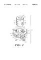
- FIG. 2is an exploded perspective view of the trial adaptor of the FIG. 1 rotated approximately ninety degrees;
- FIG. 3is a side view of the trial adaptor of FIG. 1;
- FIG. 4is a side view of a bipolar shell trial
- FIG. 4Ais a cross-sectional view of the bipolar shell trial of FIG. 4;
- FIG. 5is a cross sectional view of the trial adaptor of FIG. 1 in use with a bipolar shell trial;
- FIG. 6is a cross-sectional view of a femoral trial system of the invention.
- FIG. 7is a top or superior view of a fixed length adaptor of the invention.
- FIG. 8is a cross-sectional view of the adaptor of FIG. 7 taken along line 8--8;
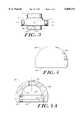
- FIG. 9is a an elevated view of a connecting element of the invention.
- FIG. 10is a cross-sectional view of the connecting element of FIG. 9 taken along line 10--10;
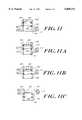
- FIG. 11is a cross-sectional view of a fixed length adaptor of the invention having a -3 mm offset
- FIG. 11Ais a cross-sectional view of a fixed length adaptor of the invention having a 0 mm offset
- FIG. 11Bis a cross-sectional view of a fixed length adaptor of the invention having a +5 mm offset.
- FIG. 11Cis a cross-sectional view of a fixed length adaptor of the invention having a +10 mm offset.
- FIGS. 1-3An adjustable trial adaptor 10 of the invention is illustrated in FIGS. 1-3.
- the adjustable trial adaptor 10includes a cylindrical portion 11 having an opening 12 extending therethrough, spring loaded ball plungers 14 extending from the outer circumference 13 of the cylindrical portion 11 and a pawl 15 extending through the outer circumference 13 of the cylindrical portion 11 partially into opening 12.
- the trial adaptorfurther includes a barrel 16 which acts as the adjustable neck portion of a unipolar head trial when the adaptor 10 is inserted into a bipolar shell.
- the barrel 16comprises three grooves 17 in the outer circumference of the barrel 16.
- the barrel 16further comprises a longitudinal slot 18 on the outer circumference 24 of the barrel 16, and openings 19 extending through the cylindrical wall 20 of the barrel.
- the barrel 16comprises a longitudinal opening 21 extending from the bottom 26 of the barrel to a top wall 22 of the barrel.
- the top wall 22includes a smaller opening 23 continuous with the opening 21.
- a dowel pin 28is press fit through the side of the cylindrical portion 11 and extends into capture slot 18 of barrel 16.
- the pin 28movably secures the cylindrical portion 11 to the barrel 16 while the capture slot 18 permits the barrel 16 to move up and down between the three neck length positions defined by the grooves 17.
- the pawl 15comprises a button portion 40, a groove engaging portion 42, and a blind hole 46 for receiving compression spring 41.
- the compression spring 41is inserted into the hole 49 in the cylindrical portion 11 and into hole 46 in pawl, aligned with hole 49 of cylindrical portion 11.
- a dowel pin 50extends into cylindrical portion 11 across hole 49 to capture the spring 41 in a compressed state in holes 46, 49.
- the pawl 15is biased by spring 41 towards the barrel 16 so that when the barrel 16 is in a locked position, the groove engaging portion 42 extends into one of the grooves 17.
- the button portion 40is exposed at the outer circumference 13 of the cylindrical portion 11 so that a user may actuate the button 40 to release the engaging portion 42 from engagement with the groove 17 and move the barrel 16 into a desired position.
- a bipolar shell trial 60shown in FIGS. 4 and 4A, and further shown mated to the adaptor 10 in FIG. 5, is spherically shaped with a flat inferior region 62.
- An adaptor-receiving opening 64is formed in the flat inferior region 62.
- a bone-contacting outer surface 66 of the shell trial 60articulates with an acetabulum.
- the shell trial 60is provided with a second, apical opening 67 which may be used to access the interior of the shell trial 60.
- the bipolar shell trial 60is available in a variety of sizes having an outer diameter ranging from about 38 to 63 millimeters and a height ranging from about 27.5 to 40 millimeters.
- the shell trial 60also has an inner, non-bone contacting surface 65 that defines a cavity extending internally within the shell 60 from the opening 64.
- the inner surface 65includes a hemispherical region 68 which may articulate with a head trial in a bipolar trial reduction that does not use an adaptor of the invention. Accordingly, a single shell trial component 60 may be used either in a bipolar trial, or with an adaptor of the invention as a head trial.
- the inner surface 65 of shell trial 60also defines an annular groove 70 and an annular shelf 72 which engage an adaptor, such as the trial adaptor 10, in concert to positively seat and retain the adaptor.
- the annular groove 70is located internally to the adaptor receiving opening 64 and is shaped to accept a connecting element on a trial adaptor such as the spring loaded ball plungers 14 of trial adaptor 10.
- the annular shelf 72also located within the opening 64, provides a positive seating means for the trial adaptor 10 with respect to the shell trial 60.
- the shell trial 60may be constructed from any material useful for temporary surgical use. Such materials include a variety of copolymers, particularly acetal copolymers, but also including polymeric material such as polyethylene, polypropylene, polyphenyl sulfone and nylon.
- a trial adaptor 10is inserted into the shell trial 60.
- the cylindrical portion 11is inserted into the adaptor-receiving opening 64 in a bipolar shell trial 60 with the barrel 16 extending down from the adaptor 10.
- the top portion 27 of the cylindrical portion 11abuts against shelf 72, and spring loaded ball plungers 14 fit into the groove 70 formed within the bipolar shell trial 60.
- the adaptormay be snapped into place within the bipolar shell trial 60 and held there by spring loaded ball plungers 14 that extend into groove 70.
- the barrel 16acts as an interface for a femoral neck trunnion 76 of the femoral trial 74.
- the femoral neck trunnion 76may be coupled to the adaptor 10 by inserting it into the opening 21 in the barrel 16.
- the barrel 16is inserted into the opening 12 of the cylindrical portion 11.
- the grooves 17serve to engage with the pawl 15 to lock the barrel 16 into a selected position corresponding to a desired neck length.
- the adaptoris arranged to extend the neck length of the femoral trial.
- the three grooves 17correspond to three different neck lengths, for example, to zero, five and ten millimeter neck lengths.
- the button portion 40 of the pawl 15is activated to release the engaging portion 42 from the groove 17 engaged by the pawl 15.
- the barrel 16is extended to a position so that the neck portion 45 of the femoral trial 44 when attached to the barrel 16 will be at a desired length.
- the button portion 40is then released causing the pawl 15 to engage the groove 17 adjacent the pawl 15, locking the barrel 16 into the desired position.
- the adjustable neck featuremay be incorporated into any trial system whether it be a unipolar, bipolar, etc. system.
- the adjustable neckmay be included with an adaptor as described or with any head or neck portion of a trial system.
- the unipolar adaptor 10may be disassembled from the bipolar shell trial 30 by pushing through the shell trial's apical hole 67 with any small diameter cylindrical instrument at hand.
- a fixed length trial adaptor 80illustrated in FIGS. 7 through 11C, may be employed in place of the adjustable trial adaptor 10.
- the fixed length trial adaptor 80includes a generally cylindrical barrel member 82 having an outer surface 84 and superior and inferior ends 86, 88.
- a circumferential flange portion 90is integral with the outer surface 84 of the barrel member between the superior and inferior ends 86, 88.
- the flange portion 90is generally cylindrical, is smaller in height than the barrel member 82 and extends radially outward from the outer surface 84 of barrel member 82 to an outer diameter D 2 .
- the barrel member 82has an inferior opening 94 and an inner surface 95 that defines a cavity 96 extending inwardly from the opening 94.
- the cavity 96is adapted to seat a femoral neck trial.
- the internal cavity 96is generally cylindrical and extends from the inferior opening 94 superiorly to an end region 98 against which a femoral neck trunnion abuts.
- the cavity 96may be tapered so as to fit conventional neck trial trunnions which are also tapered.
- taperscan be used. Common tapers include 10/12 and 11/13 sizes in which the two numbers in each size designation represent the diameter of the neck measured at two different points along its length.
- Grooves 100, 102may be provided within the cavity 96 for seating one O-ring 104, 106 each.
- the O-rings 104, 106which are preferably formed from a silicone rubber material, allow the adaptor 80 to mate snugly with a neck trial trunnion even where dimensions of the trunnion vary from a trial to a permanent prosthesis or among different manufacturers who may have different standards for measuring or sizing the tapers.
- the O-ringsallow the mating between the neck and adaptor 80 to take place at two points along the length of the cavity 96. This configuration is preferable to direct mating along the length of the cavity 96 which can make it difficult to remove the trial adaptor 80 from the neck.
- flange portion 90has a groove 108 about its outer circumference suitable for seating a resilient connecting element 110.
- the connecting element 110in an embodiment illustrated in FIGS. 9 and 10, is an arc member having an inner diameter 112 that exceeds the diameter D 1 the groove 108 so that, when the connecting element 110 is in an a first, unflexed position, a clearance 114 (shown in FIG. 8) exists between the groove 108 and the connecting element 110.
- the nominal (unflexed) outer diameter 116 of the connecting element 110also exceeds the outer diameter D 2 of the flange portion 90, preferably by about 0.05 to 0.11 inch.
- the connecting element 110is made from a flexible material so that the arc may be compressed from a first, unflexed position to a second, compressed position wherein the connecting element 110 maintains a second outer diameter that is less than its nominal outer diameter 116 in response to a compressive force such as when the adaptor 80 is pressed into the shell trial 60.
- the exemplary connecting element 110may be formed as a complete ring, but a portion corresponding to an angle ⁇ is preferably removed from the connecting element 110.
- the removed portion ⁇may generally be an arc of between about 10° to 60°, and preferably is an arc of about 30°.
- connecting element 110may be made from a variety of resilient materials that possess shape memory. Such materials include polymeric materials as well as metallic materials. Exemplary materials include acetal copolymer, polyethylene, polypropylene, polyphenyl sulfone and nylon.
- the connecting element 110When the adaptor 80 is inserted into the shell 60, contact forces from the inner cavity 65 of the shell trial 60 compress the resilient connecting element 110 from its first, nominal outer diameter 116 to its second, compressed outer diameter and the adaptor 80 slides into the shell trial 60.
- the connecting element 100When the flange portion 90 meets the annular shelf 72 within the shell trial opening 64, the connecting element 100 correspondingly becomes aligned with the annular groove 70 and the resilient connecting element 110 expands to mate with the groove 70 and thereby secures the adaptor 80 to the shell trial 60.
- the connecting element 110preferably has a rounded outer edge 118 configured to correspond to the shape of the annular groove 70 to facilitate mating therewith.
- the fixed length trial adaptor 80may be removed from a shell trial by inserting an appropriate tool through the apical hole 67 in the shell trial as described with respect to the adjustable length adaptor 10.
- the adaptor 80may further be provided with an oblong opening 120 on its superior end 86.
- a tool(not shown) having a cylindrical insertion member and a cross member proximate to its insertion end may be inserted through the oblong opening 120 from the inferior side with the cross-member aligned with the oblong hole 120.
- the toolmay then be rotated 90° so that the cross member is no longer aligned with the oblong hole 120.
- the adaptor 80can then be separated from the shell 60 by pulling on the tool with sufficient force to compress the resilient connecting element 110 and remove the adaptor 80.
- Trials of various neck trunnionsmay be simulated using fixed length trial adaptors having different effective lengths.
- the effective length of the trial adaptor 80may be varied, for example, by locating the circumferential flange portion 90 at different positions along the barrel member 82.
- the location of the end region 98 of the barrel's internal cavity 96may also be varied to this effect.
- Fixed length trial adaptors 80 having relative effective lengths of -3 mm, 0 mm, +5 mm and +10 mmare illustrated in FIGS. 11, 11A, 11B and 11C, respectively.
- a physicianmay elect during surgery to convert the bipolar shell trial into a unipolar head by inserting the adjustable length unipolar trial adaptor 10 or the fixed length unipolar trial adaptor 80 into shell 60.
- Use of either adaptorallows a physician to adjust the fit of the head or the bipolar shell and reduce the femur while electing the appropriate neck length without the usual cumbersome bipolar trial system.
- the trial systempreferably includes various bipolar shell sizes and various femoral stem sizes to allow the surgeon to select the appropriate size while performing a trial reduction.
- the trial systempreferably includes a plurality of adaptors 80 representing different relative neck lengths.
Landscapes
- Health & Medical Sciences (AREA)
- Transplantation (AREA)
- Orthopedic Medicine & Surgery (AREA)
- Heart & Thoracic Surgery (AREA)
- Cardiology (AREA)
- Oral & Maxillofacial Surgery (AREA)
- Engineering & Computer Science (AREA)
- Biomedical Technology (AREA)
- Physical Education & Sports Medicine (AREA)
- Vascular Medicine (AREA)
- Life Sciences & Earth Sciences (AREA)
- Animal Behavior & Ethology (AREA)
- General Health & Medical Sciences (AREA)
- Public Health (AREA)
- Veterinary Medicine (AREA)
- Prostheses (AREA)
Abstract
Description
Claims (25)
Priority Applications (2)
| Application Number | Priority Date | Filing Date | Title |
|---|---|---|---|
| US08/910,617US5888211A (en) | 1996-05-23 | 1997-08-13 | Bipolar-unipolar adaptor for a head trial |
| JP23944398AJP4215867B2 (en) | 1997-08-13 | 1998-08-12 | Bipolar-unipolar type femoral head adapter |
Applications Claiming Priority (2)
| Application Number | Priority Date | Filing Date | Title |
|---|---|---|---|
| US08/652,764US5800556A (en) | 1996-05-23 | 1996-05-23 | Adjustable bipolar-unipolar adaptor for a head trial |
| US08/910,617US5888211A (en) | 1996-05-23 | 1997-08-13 | Bipolar-unipolar adaptor for a head trial |
Related Parent Applications (1)
| Application Number | Title | Priority Date | Filing Date |
|---|---|---|---|
| US08/652,764Continuation-In-PartUS5800556A (en) | 1996-05-23 | 1996-05-23 | Adjustable bipolar-unipolar adaptor for a head trial |
Publications (1)
| Publication Number | Publication Date |
|---|---|
| US5888211Atrue US5888211A (en) | 1999-03-30 |
Family
ID=46203176
Family Applications (1)
| Application Number | Title | Priority Date | Filing Date |
|---|---|---|---|
| US08/910,617Expired - Fee RelatedUS5888211A (en) | 1996-05-23 | 1997-08-13 | Bipolar-unipolar adaptor for a head trial |
Country Status (1)
| Country | Link |
|---|---|
| US (1) | US5888211A (en) |
Cited By (43)
| Publication number | Priority date | Publication date | Assignee | Title |
|---|---|---|---|---|
| US5993457A (en)* | 1998-09-17 | 1999-11-30 | The Regents Of The University Of California | Measurement device and method for total hip arthroplasty |
| US6126694A (en)* | 1999-03-05 | 2000-10-03 | Sulzer Orthopedics Inc. | Universal distal broach and stem trial |
| US20040024468A1 (en)* | 2002-08-05 | 2004-02-05 | Gabriele Lualdi | Femoral prosthesis for hip articulation |
| US20040054418A1 (en)* | 2002-09-13 | 2004-03-18 | Mclean Terry | Prostheses |
| WO2004108024A1 (en)* | 2003-06-06 | 2004-12-16 | Biomet Merck Limited | Surgical device |
| US6926740B2 (en) | 2002-12-13 | 2005-08-09 | Depuy Products, Inc. | Modular orthopaedic implant apparatus and method |
| US20060058886A1 (en)* | 2004-09-13 | 2006-03-16 | Finsbury (Development) Limited | Tool |
| EP1679051A1 (en)* | 2005-01-11 | 2006-07-12 | Benoist Girard Sas | Trial bearing insert |
| US7179297B2 (en) | 2002-09-17 | 2007-02-20 | Smith & Nephew, Inc. | Combined bipolar and unipolar trials |
| US20070213833A1 (en)* | 2000-04-26 | 2007-09-13 | Zimmer Technology, Inc. | Method and apparatus for performing a minimally invasive total hip arthroplasty |
| US20080053169A1 (en)* | 2006-08-30 | 2008-03-06 | Victoria Marie Ricker | Theft deterrent device for bags |
| US7445639B2 (en) | 2001-02-23 | 2008-11-04 | Biomet Manufacturing Corp. | Knee joint prosthesis |
| WO2009023971A1 (en)* | 2007-08-21 | 2009-02-26 | Socovar Societe En Commandite | Trial insert for use in orthopaedic surgery |
| US7497874B1 (en) | 2001-02-23 | 2009-03-03 | Biomet Manufacturing Corp. | Knee joint prosthesis |
| US20090281632A1 (en)* | 2008-05-09 | 2009-11-12 | Remi Sciences, Inc. | Ulnar head prosthesis system |
| US20090281631A1 (en)* | 2008-05-09 | 2009-11-12 | Remi Sciences, Inc. | Ulnar head prosthesis system |
| US8157869B2 (en) | 2007-01-10 | 2012-04-17 | Biomet Manufacturing Corp. | Knee joint prosthesis system and method for implantation |
| US8163028B2 (en) | 2007-01-10 | 2012-04-24 | Biomet Manufacturing Corp. | Knee joint prosthesis system and method for implantation |
| US8187280B2 (en) | 2007-10-10 | 2012-05-29 | Biomet Manufacturing Corp. | Knee joint prosthesis system and method for implantation |
| US8328873B2 (en) | 2007-01-10 | 2012-12-11 | Biomet Manufacturing Corp. | Knee joint prosthesis system and method for implantation |
| US20130197656A1 (en)* | 2012-02-01 | 2013-08-01 | Zimmer, Inc. | Adjustable provisional component of a medical device |
| US8562616B2 (en) | 2007-10-10 | 2013-10-22 | Biomet Manufacturing, Llc | Knee joint prosthesis system and method for implantation |
| WO2014140636A1 (en)* | 2013-03-15 | 2014-09-18 | Depuy (Ireland) | Implant trialling |
| WO2014140639A1 (en)* | 2013-03-15 | 2014-09-18 | Depuy (Ireland) | Implant trialling |
| US20150250620A1 (en)* | 2014-03-10 | 2015-09-10 | Biomet Manufacturing, Llc | Adjustable Modular Prosthesis |
| FR3035319A1 (en)* | 2015-04-23 | 2016-10-28 | Cie Financiere Et Medicale | ASSEMBLY OF ELEMENTS FOR RECONSTITUTING BONE JOINT BETWEEN LONG BONE AND CONJUGATED BONE |
| US9636228B2 (en) | 2007-02-10 | 2017-05-02 | Howmedica Osteonics Corp. | Radial head implant |
| US9655726B2 (en) | 2004-12-01 | 2017-05-23 | Mayo Foundation For Medical Research And Education | Radial-capitellar implant |
| US9724201B2 (en)* | 2015-06-30 | 2017-08-08 | Depuy Ireland Unlimited Company | Modular taper seal for orthopaedic prosthetic hip assembly |
| US20170333192A1 (en)* | 2016-05-17 | 2017-11-23 | Diange Zhou | Non-metal Ball-headed Hip Joint Prosthesis |
| US10111754B2 (en) | 2016-09-30 | 2018-10-30 | Depuy Ireland Unlimited Company | Acetabular shell and liner system |
| US10596005B2 (en) | 2017-04-28 | 2020-03-24 | Hector Noel | Frictionless hip joint |
| US11129733B2 (en) | 2019-05-01 | 2021-09-28 | Stephen Patrick Morrisey | Hip arthroplasty trial systems and associated medical devices, methods, and kits |
| US11224517B2 (en)* | 2019-06-26 | 2022-01-18 | DePuy Synthes Products, Inc. | Mechanically coupled revision hip system and method |
| US11291549B2 (en) | 2019-12-11 | 2022-04-05 | Depuy Ireland Unlimited Company | Ceramic acetabular shell liners with augments |
| US11331192B2 (en) | 2017-04-28 | 2022-05-17 | Noel Raels Ortho Devices Incorporated | Frictionless hip joint |
| US11344437B2 (en)* | 2017-10-03 | 2022-05-31 | Depuy Ireland Unlimited Company | Trial neck apparatus and method |
| US11376128B2 (en) | 2018-12-31 | 2022-07-05 | Depuy Ireland Unlimited Company | Acetabular orthopaedic prosthesis and method |
| US20220249256A1 (en)* | 2021-02-02 | 2022-08-11 | Depuy Synthes Products, Nc. | Trial neck and method |
| US20220346977A1 (en)* | 2021-04-29 | 2022-11-03 | Stephen Patrick Morrisey | Offset Adjustable Neck Length Trial Device and System for Hip Arthroplasty |
| US11628066B2 (en) | 2019-12-11 | 2023-04-18 | Depuy Ireland Unlimited Company | Ceramic acetabular shell liner with a metal ring having a lead-in surface |
| US11826267B2 (en) | 2017-04-12 | 2023-11-28 | Depuy Ireland Unlimited Company | Femoral trialling kit and assembly |
| US12171666B2 (en) | 2019-12-10 | 2024-12-24 | Depuy Ireland Unlimited Company | Metal reinforced acetabular shell liner |
Citations (9)
| Publication number | Priority date | Publication date | Assignee | Title |
|---|---|---|---|---|
| US5108452A (en)* | 1989-02-08 | 1992-04-28 | Smith & Nephew Richards Inc. | Modular hip prosthesis |
| US5156624A (en)* | 1991-09-06 | 1992-10-20 | Zimmer, Inc. | Head adaptor for hip prosthesis |
| US5156626A (en)* | 1990-06-29 | 1992-10-20 | Zimmer, Inc. | Set of provisional prosthesis instrumentation |
| US5358524A (en)* | 1993-02-16 | 1994-10-25 | Wright Medical Technology, Inc. | Adjustable length prosthetic implant |
| US5383938A (en)* | 1993-02-12 | 1995-01-24 | Zimmer, Inc. | Locking ring for an acetabular cup |
| US5405394A (en)* | 1992-03-24 | 1995-04-11 | Smith & Nephew Richards, Inc. | Dual composition coupler for modular medical implants |
| US5569263A (en)* | 1995-01-12 | 1996-10-29 | Orthopaedic Innovations, Inc. | Adjustable provisional articulating device |
| US5645607A (en)* | 1995-03-02 | 1997-07-08 | Zimmer, Inc. | Hip stem provisional having adjustable neck offsets |
| US5658340A (en)* | 1993-08-16 | 1997-08-19 | Howmedica Gmbh | Endoprosthesis for a shoulder joint |
- 1997
- 1997-08-13USUS08/910,617patent/US5888211A/ennot_activeExpired - Fee Related
Patent Citations (9)
| Publication number | Priority date | Publication date | Assignee | Title |
|---|---|---|---|---|
| US5108452A (en)* | 1989-02-08 | 1992-04-28 | Smith & Nephew Richards Inc. | Modular hip prosthesis |
| US5156626A (en)* | 1990-06-29 | 1992-10-20 | Zimmer, Inc. | Set of provisional prosthesis instrumentation |
| US5156624A (en)* | 1991-09-06 | 1992-10-20 | Zimmer, Inc. | Head adaptor for hip prosthesis |
| US5405394A (en)* | 1992-03-24 | 1995-04-11 | Smith & Nephew Richards, Inc. | Dual composition coupler for modular medical implants |
| US5383938A (en)* | 1993-02-12 | 1995-01-24 | Zimmer, Inc. | Locking ring for an acetabular cup |
| US5358524A (en)* | 1993-02-16 | 1994-10-25 | Wright Medical Technology, Inc. | Adjustable length prosthetic implant |
| US5658340A (en)* | 1993-08-16 | 1997-08-19 | Howmedica Gmbh | Endoprosthesis for a shoulder joint |
| US5569263A (en)* | 1995-01-12 | 1996-10-29 | Orthopaedic Innovations, Inc. | Adjustable provisional articulating device |
| US5645607A (en)* | 1995-03-02 | 1997-07-08 | Zimmer, Inc. | Hip stem provisional having adjustable neck offsets |
Cited By (80)
| Publication number | Priority date | Publication date | Assignee | Title |
|---|---|---|---|---|
| WO2000015124A1 (en)* | 1998-09-17 | 2000-03-23 | The Regents Of The University Of California | Measurement device and method for total hip arthroplasty |
| US5993457A (en)* | 1998-09-17 | 1999-11-30 | The Regents Of The University Of California | Measurement device and method for total hip arthroplasty |
| US6126694A (en)* | 1999-03-05 | 2000-10-03 | Sulzer Orthopedics Inc. | Universal distal broach and stem trial |
| US20070213833A1 (en)* | 2000-04-26 | 2007-09-13 | Zimmer Technology, Inc. | Method and apparatus for performing a minimally invasive total hip arthroplasty |
| US7497874B1 (en) | 2001-02-23 | 2009-03-03 | Biomet Manufacturing Corp. | Knee joint prosthesis |
| US7445639B2 (en) | 2001-02-23 | 2008-11-04 | Biomet Manufacturing Corp. | Knee joint prosthesis |
| US20040024468A1 (en)* | 2002-08-05 | 2004-02-05 | Gabriele Lualdi | Femoral prosthesis for hip articulation |
| EP1388329A1 (en)* | 2002-08-05 | 2004-02-11 | LIMA Lto SpA | Femoral prosthesis for hip joint |
| US8753404B2 (en) | 2002-09-13 | 2014-06-17 | Smith & Nephew, Inc. | Hip prostheses |
| US20040054418A1 (en)* | 2002-09-13 | 2004-03-18 | Mclean Terry | Prostheses |
| US8603182B2 (en) | 2002-09-13 | 2013-12-10 | Smith & Nephew, Inc. | Hip prostheses |
| US6986792B2 (en) | 2002-09-13 | 2006-01-17 | Smith & Nephew, Inc. | Prostheses |
| US20080015707A1 (en)* | 2002-09-13 | 2008-01-17 | Richard Lambert | Hip prostheses |
| US20060217814A1 (en)* | 2002-09-13 | 2006-09-28 | Smith & Nephew, Inc. | Hip prostheses |
| US7179297B2 (en) | 2002-09-17 | 2007-02-20 | Smith & Nephew, Inc. | Combined bipolar and unipolar trials |
| US7264636B2 (en) | 2002-12-13 | 2007-09-04 | Depuy Products, Inc. | Modular orthopaedic implant apparatus |
| US20050246026A1 (en)* | 2002-12-13 | 2005-11-03 | Lewis Paul P | Modular orthopaedic implant apparatus |
| US8597364B2 (en) | 2002-12-13 | 2013-12-03 | DePuy Synthes Products, LLC | Prosthesis implantation method |
| US6926740B2 (en) | 2002-12-13 | 2005-08-09 | Depuy Products, Inc. | Modular orthopaedic implant apparatus and method |
| US20110077745A1 (en)* | 2002-12-13 | 2011-03-31 | Depuy Products, Inc. | Prosthesis Implantation Method |
| US7846212B2 (en) | 2002-12-13 | 2010-12-07 | Depuy Products, Inc. | Modular orthopaedic implant apparatus |
| US20060241625A1 (en)* | 2003-06-06 | 2006-10-26 | Biomet Merck Limited | Surgical device |
| US8449619B2 (en) | 2003-06-06 | 2013-05-28 | Biomet Uk Limited | Hip stem instrument with releasable connection |
| WO2004108024A1 (en)* | 2003-06-06 | 2004-12-16 | Biomet Merck Limited | Surgical device |
| US20060058886A1 (en)* | 2004-09-13 | 2006-03-16 | Finsbury (Development) Limited | Tool |
| EP1634551A3 (en)* | 2004-09-13 | 2006-03-22 | Finsbury (Development) Limited | Surgical tool |
| US9655726B2 (en) | 2004-12-01 | 2017-05-23 | Mayo Foundation For Medical Research And Education | Radial-capitellar implant |
| US20060173548A1 (en)* | 2005-01-11 | 2006-08-03 | Arnaud Auxepaules | Retentive and removable trial bearing insert |
| EP1679051A1 (en)* | 2005-01-11 | 2006-07-12 | Benoist Girard Sas | Trial bearing insert |
| US8114166B2 (en) | 2005-01-11 | 2012-02-14 | Benoist Girard Sas | Retentive and removable trial bearing insert |
| US20080053169A1 (en)* | 2006-08-30 | 2008-03-06 | Victoria Marie Ricker | Theft deterrent device for bags |
| US8328873B2 (en) | 2007-01-10 | 2012-12-11 | Biomet Manufacturing Corp. | Knee joint prosthesis system and method for implantation |
| US8163028B2 (en) | 2007-01-10 | 2012-04-24 | Biomet Manufacturing Corp. | Knee joint prosthesis system and method for implantation |
| US8936648B2 (en) | 2007-01-10 | 2015-01-20 | Biomet Manufacturing, Llc | Knee joint prosthesis system and method for implantation |
| US8157869B2 (en) | 2007-01-10 | 2012-04-17 | Biomet Manufacturing Corp. | Knee joint prosthesis system and method for implantation |
| US8480751B2 (en) | 2007-01-10 | 2013-07-09 | Biomet Manufacturing, Llc | Knee joint prosthesis system and method for implantation |
| US9636228B2 (en) | 2007-02-10 | 2017-05-02 | Howmedica Osteonics Corp. | Radial head implant |
| WO2009023971A1 (en)* | 2007-08-21 | 2009-02-26 | Socovar Societe En Commandite | Trial insert for use in orthopaedic surgery |
| US10736747B2 (en) | 2007-10-10 | 2020-08-11 | Biomet Manufacturing, Llc | Knee joint prosthesis system and method for implantation |
| US8187280B2 (en) | 2007-10-10 | 2012-05-29 | Biomet Manufacturing Corp. | Knee joint prosthesis system and method for implantation |
| US8562616B2 (en) | 2007-10-10 | 2013-10-22 | Biomet Manufacturing, Llc | Knee joint prosthesis system and method for implantation |
| US9763793B2 (en) | 2007-10-10 | 2017-09-19 | Biomet Manufacturing, Llc | Knee joint prosthesis system and method for implantation |
| US20090281631A1 (en)* | 2008-05-09 | 2009-11-12 | Remi Sciences, Inc. | Ulnar head prosthesis system |
| US8052755B2 (en)* | 2008-05-09 | 2011-11-08 | Remi Sciences, Inc. | Ulnar head prosthesis system |
| US20090281632A1 (en)* | 2008-05-09 | 2009-11-12 | Remi Sciences, Inc. | Ulnar head prosthesis system |
| US7875082B2 (en)* | 2008-05-09 | 2011-01-25 | Remi Sciences, Inc. | Ulnar head prosthesis system |
| US20130197656A1 (en)* | 2012-02-01 | 2013-08-01 | Zimmer, Inc. | Adjustable provisional component of a medical device |
| US9216086B2 (en)* | 2012-02-01 | 2015-12-22 | Zimmer, Inc. | Adjustable provisional component of a medical device |
| CN105431111A (en)* | 2013-03-15 | 2016-03-23 | 德普伊(爱尔兰)有限公司 | Implant trialing |
| CN105592823A (en)* | 2013-03-15 | 2016-05-18 | 德普伊(爱尔兰)有限公司 | Implant Trialling |
| AU2014229730B2 (en)* | 2013-03-15 | 2018-12-13 | Depuy (Ireland) | Implant trialling |
| WO2014140636A1 (en)* | 2013-03-15 | 2014-09-18 | Depuy (Ireland) | Implant trialling |
| WO2014140639A1 (en)* | 2013-03-15 | 2014-09-18 | Depuy (Ireland) | Implant trialling |
| RU2663714C2 (en)* | 2013-03-15 | 2018-08-08 | Депью (Айэлэнд) | Implant trialling |
| RU2664165C2 (en)* | 2013-03-15 | 2018-08-15 | Депью (Айэлэнд) | Implant trialling |
| AU2014229727B2 (en)* | 2013-03-15 | 2018-09-27 | Depuy Ireland Unlimited Company | Implant trialling |
| US9615943B2 (en)* | 2014-03-10 | 2017-04-11 | Biomet Manufacturing, Llc | Adjustable modular prosthesis |
| US20150250620A1 (en)* | 2014-03-10 | 2015-09-10 | Biomet Manufacturing, Llc | Adjustable Modular Prosthesis |
| FR3035319A1 (en)* | 2015-04-23 | 2016-10-28 | Cie Financiere Et Medicale | ASSEMBLY OF ELEMENTS FOR RECONSTITUTING BONE JOINT BETWEEN LONG BONE AND CONJUGATED BONE |
| US10322003B2 (en) | 2015-06-30 | 2019-06-18 | Depuy Ireland Unlimited Company | Modular taper seal and method for orthopaedic prosthetic hip assembly |
| US9724201B2 (en)* | 2015-06-30 | 2017-08-08 | Depuy Ireland Unlimited Company | Modular taper seal for orthopaedic prosthetic hip assembly |
| US20170333192A1 (en)* | 2016-05-17 | 2017-11-23 | Diange Zhou | Non-metal Ball-headed Hip Joint Prosthesis |
| US10111754B2 (en) | 2016-09-30 | 2018-10-30 | Depuy Ireland Unlimited Company | Acetabular shell and liner system |
| US11826267B2 (en) | 2017-04-12 | 2023-11-28 | Depuy Ireland Unlimited Company | Femoral trialling kit and assembly |
| US10596005B2 (en) | 2017-04-28 | 2020-03-24 | Hector Noel | Frictionless hip joint |
| US11331192B2 (en) | 2017-04-28 | 2022-05-17 | Noel Raels Ortho Devices Incorporated | Frictionless hip joint |
| US11344437B2 (en)* | 2017-10-03 | 2022-05-31 | Depuy Ireland Unlimited Company | Trial neck apparatus and method |
| US11376128B2 (en) | 2018-12-31 | 2022-07-05 | Depuy Ireland Unlimited Company | Acetabular orthopaedic prosthesis and method |
| US11660213B2 (en) | 2019-05-01 | 2023-05-30 | Stephen Patrick Morrisey | Hip arthroplasty trial systems and associated medical devices, methods, and kits |
| US11129733B2 (en) | 2019-05-01 | 2021-09-28 | Stephen Patrick Morrisey | Hip arthroplasty trial systems and associated medical devices, methods, and kits |
| US12376974B2 (en) | 2019-05-01 | 2025-08-05 | Stephen Patrick Morrisey | Hip arthroplasty trial systems and associated medical devices, methods, and kits |
| US12004968B2 (en) | 2019-05-01 | 2024-06-11 | Stephen Patrick Morrisey | Hip arthroplasty trial systems and associated medical devices, methods, and kits |
| US11224517B2 (en)* | 2019-06-26 | 2022-01-18 | DePuy Synthes Products, Inc. | Mechanically coupled revision hip system and method |
| US12171666B2 (en) | 2019-12-10 | 2024-12-24 | Depuy Ireland Unlimited Company | Metal reinforced acetabular shell liner |
| US11628066B2 (en) | 2019-12-11 | 2023-04-18 | Depuy Ireland Unlimited Company | Ceramic acetabular shell liner with a metal ring having a lead-in surface |
| US12274623B2 (en) | 2019-12-11 | 2025-04-15 | Depuy Ireland Unlimited Company | Ceramic acetabular shell liners with augments |
| US11291549B2 (en) | 2019-12-11 | 2022-04-05 | Depuy Ireland Unlimited Company | Ceramic acetabular shell liners with augments |
| US20220249256A1 (en)* | 2021-02-02 | 2022-08-11 | Depuy Synthes Products, Nc. | Trial neck and method |
| US20220346977A1 (en)* | 2021-04-29 | 2022-11-03 | Stephen Patrick Morrisey | Offset Adjustable Neck Length Trial Device and System for Hip Arthroplasty |
| US12023261B2 (en)* | 2021-04-29 | 2024-07-02 | Stephen Patrick Morrisey | Offset adjustable neck length trial device and system for hip arthroplasty |
Similar Documents
| Publication | Publication Date | Title |
|---|---|---|
| US5888211A (en) | Bipolar-unipolar adaptor for a head trial | |
| US7179297B2 (en) | Combined bipolar and unipolar trials | |
| US5658294A (en) | Instrument for holding an acetabular cup | |
| JP4034378B2 (en) | Alternative femoral head adapter, alternative femoral head system and alternative femoral head | |
| US6916342B2 (en) | Liner assembly for prosthetic components | |
| US7179296B2 (en) | Partially constrained ball and socket | |
| EP2082705B1 (en) | Constraining ring inserter | |
| US7025788B2 (en) | Knee joint prosthesis | |
| US5156626A (en) | Set of provisional prosthesis instrumentation | |
| JP2749204B2 (en) | Acetabular cup positioning insert with release mechanism | |
| US7338528B2 (en) | Humeral stem with anatomical location of taper access for fixation of humeral head | |
| JP4057068B2 (en) | Lock mechanism for acetabular cup | |
| US6926740B2 (en) | Modular orthopaedic implant apparatus and method | |
| US8147498B2 (en) | Method and apparatus for assembling implants | |
| EP2055274B1 (en) | Taper Sleeve Extractor | |
| EP2316386A1 (en) | Shoulder prosthesis component | |
| US20100222891A1 (en) | Modular implant system with fully porous coated sleeve | |
| EP1411868A2 (en) | Method and apparatus for use of a metal-metal constrained liner | |
| JP4215867B2 (en) | Bipolar-unipolar type femoral head adapter | |
| US8449619B2 (en) | Hip stem instrument with releasable connection | |
| US7172598B2 (en) | Force specific impacting device | |
| JP2014507977A (en) | Sockets, especially acetabular sockets for hip prostheses | |
| CN116887787A (en) | Interlocking reverse hip prosthesis with removable tapered center post |
Legal Events
| Date | Code | Title | Description |
|---|---|---|---|
| AS | Assignment | Owner name:JOHNSON & JOHNSON PROFESSIONAL, INC., MASSACHUSETT Free format text:ASSIGNMENT OF ASSIGNORS INTEREST;ASSIGNOR:SANDERS, ANTHONY P.;REEL/FRAME:008959/0815 Effective date:19970919 | |
| AS | Assignment | Owner name:DEPUY ORTHOPAEDICS, INC., NEW JERSEY Free format text:MERGER;ASSIGNOR:CASES TO BE RECORDED IN THE NAME OF DEPUY ORTHOPAEDICS, INC.;REEL/FRAME:010725/0402 Effective date:19990703 | |
| FEPP | Fee payment procedure | Free format text:PAYOR NUMBER ASSIGNED (ORIGINAL EVENT CODE: ASPN); ENTITY STATUS OF PATENT OWNER: LARGE ENTITY | |
| FPAY | Fee payment | Year of fee payment:4 | |
| FPAY | Fee payment | Year of fee payment:8 | |
| REMI | Maintenance fee reminder mailed | ||
| LAPS | Lapse for failure to pay maintenance fees | ||
| LAPS | Lapse for failure to pay maintenance fees | Free format text:PATENT EXPIRED FOR FAILURE TO PAY MAINTENANCE FEES (ORIGINAL EVENT CODE: EXP.); ENTITY STATUS OF PATENT OWNER: LARGE ENTITY | |
| STCH | Information on status: patent discontinuation | Free format text:PATENT EXPIRED DUE TO NONPAYMENT OF MAINTENANCE FEES UNDER 37 CFR 1.362 | |
| FP | Lapsed due to failure to pay maintenance fee | Effective date:20110330 |