US5888204A - Acetabular cup having capped polyaxial locking screws - Google Patents
Acetabular cup having capped polyaxial locking screwsDownload PDFInfo
- Publication number
- US5888204A US5888204AUS08/843,972US84397297AUS5888204AUS 5888204 AUS5888204 AUS 5888204AUS 84397297 AUS84397297 AUS 84397297AUS 5888204 AUS5888204 AUS 5888204A
- Authority
- US
- United States
- Prior art keywords
- screw
- hole
- socket portion
- socket
- head
- Prior art date
- Legal status (The legal status is an assumption and is not a legal conclusion. Google has not performed a legal analysis and makes no representation as to the accuracy of the status listed.)
- Expired - Lifetime
Links
- 210000000988bone and boneAnatomy0.000claimsabstractdescription45
- 230000008878couplingEffects0.000claimsabstractdescription35
- 238000010168coupling processMethods0.000claimsabstractdescription35
- 238000005859coupling reactionMethods0.000claimsabstractdescription35
- 238000004873anchoringMethods0.000claimsabstractdescription7
- 238000003780insertionMethods0.000claimsdescription6
- 230000037431insertionEffects0.000claimsdescription6
- 230000000717retained effectEffects0.000claimsdescription3
- 238000009877renderingMethods0.000claims1
- 210000001624hipAnatomy0.000description9
- 229910052751metalInorganic materials0.000description5
- 239000002184metalSubstances0.000description5
- 239000000919ceramicSubstances0.000description4
- 239000007943implantSubstances0.000description3
- 239000000463materialSubstances0.000description3
- 238000000034methodMethods0.000description3
- 210000000588acetabulumAnatomy0.000description2
- 238000004519manufacturing processMethods0.000description2
- 210000004197pelvisAnatomy0.000description2
- 229920000642polymerPolymers0.000description2
- 230000008569processEffects0.000description2
- 210000000689upper legAnatomy0.000description2
- 229910000831SteelInorganic materials0.000description1
- 229910001069Ti alloyInorganic materials0.000description1
- 230000000712assemblyEffects0.000description1
- 238000000429assemblyMethods0.000description1
- 239000000560biocompatible materialSubstances0.000description1
- 230000000694effectsEffects0.000description1
- 210000004394hip jointAnatomy0.000description1
- 238000002513implantationMethods0.000description1
- 210000001503jointAnatomy0.000description1
- 230000007774longtermEffects0.000description1
- 230000013011matingEffects0.000description1
- 230000007246mechanismEffects0.000description1
- 238000012986modificationMethods0.000description1
- 230000004048modificationEffects0.000description1
- 238000001228spectrumMethods0.000description1
- 239000010959steelSubstances0.000description1
Images


Classifications
- A—HUMAN NECESSITIES
- A61—MEDICAL OR VETERINARY SCIENCE; HYGIENE
- A61F—FILTERS IMPLANTABLE INTO BLOOD VESSELS; PROSTHESES; DEVICES PROVIDING PATENCY TO, OR PREVENTING COLLAPSING OF, TUBULAR STRUCTURES OF THE BODY, e.g. STENTS; ORTHOPAEDIC, NURSING OR CONTRACEPTIVE DEVICES; FOMENTATION; TREATMENT OR PROTECTION OF EYES OR EARS; BANDAGES, DRESSINGS OR ABSORBENT PADS; FIRST-AID KITS
- A61F2/00—Filters implantable into blood vessels; Prostheses, i.e. artificial substitutes or replacements for parts of the body; Appliances for connecting them with the body; Devices providing patency to, or preventing collapsing of, tubular structures of the body, e.g. stents
- A61F2/02—Prostheses implantable into the body
- A61F2/30—Joints
- A61F2/30721—Accessories
- A61F2/30749—Fixation appliances for connecting prostheses to the body
- A—HUMAN NECESSITIES
- A61—MEDICAL OR VETERINARY SCIENCE; HYGIENE
- A61F—FILTERS IMPLANTABLE INTO BLOOD VESSELS; PROSTHESES; DEVICES PROVIDING PATENCY TO, OR PREVENTING COLLAPSING OF, TUBULAR STRUCTURES OF THE BODY, e.g. STENTS; ORTHOPAEDIC, NURSING OR CONTRACEPTIVE DEVICES; FOMENTATION; TREATMENT OR PROTECTION OF EYES OR EARS; BANDAGES, DRESSINGS OR ABSORBENT PADS; FIRST-AID KITS
- A61F2/00—Filters implantable into blood vessels; Prostheses, i.e. artificial substitutes or replacements for parts of the body; Appliances for connecting them with the body; Devices providing patency to, or preventing collapsing of, tubular structures of the body, e.g. stents
- A61F2/02—Prostheses implantable into the body
- A61F2/30—Joints
- A61F2/30721—Accessories
- A61F2/30744—End caps, e.g. for closing an endoprosthetic cavity
- A—HUMAN NECESSITIES
- A61—MEDICAL OR VETERINARY SCIENCE; HYGIENE
- A61F—FILTERS IMPLANTABLE INTO BLOOD VESSELS; PROSTHESES; DEVICES PROVIDING PATENCY TO, OR PREVENTING COLLAPSING OF, TUBULAR STRUCTURES OF THE BODY, e.g. STENTS; ORTHOPAEDIC, NURSING OR CONTRACEPTIVE DEVICES; FOMENTATION; TREATMENT OR PROTECTION OF EYES OR EARS; BANDAGES, DRESSINGS OR ABSORBENT PADS; FIRST-AID KITS
- A61F2/00—Filters implantable into blood vessels; Prostheses, i.e. artificial substitutes or replacements for parts of the body; Appliances for connecting them with the body; Devices providing patency to, or preventing collapsing of, tubular structures of the body, e.g. stents
- A61F2/02—Prostheses implantable into the body
- A61F2/30—Joints
- A61F2/32—Joints for the hip
- A61F2/34—Acetabular cups
- A—HUMAN NECESSITIES
- A61—MEDICAL OR VETERINARY SCIENCE; HYGIENE
- A61B—DIAGNOSIS; SURGERY; IDENTIFICATION
- A61B17/00—Surgical instruments, devices or methods
- A61B17/56—Surgical instruments or methods for treatment of bones or joints; Devices specially adapted therefor
- A61B17/58—Surgical instruments or methods for treatment of bones or joints; Devices specially adapted therefor for osteosynthesis, e.g. bone plates, screws or setting implements
- A61B17/68—Internal fixation devices, including fasteners and spinal fixators, even if a part thereof projects from the skin
- A61B17/80—Cortical plates, i.e. bone plates; Instruments for holding or positioning cortical plates, or for compressing bones attached to cortical plates
- A61B17/8033—Cortical plates, i.e. bone plates; Instruments for holding or positioning cortical plates, or for compressing bones attached to cortical plates having indirect contact with screw heads, or having contact with screw heads maintained with the aid of additional components, e.g. nuts, wedges or head covers
- A61B17/8047—Cortical plates, i.e. bone plates; Instruments for holding or positioning cortical plates, or for compressing bones attached to cortical plates having indirect contact with screw heads, or having contact with screw heads maintained with the aid of additional components, e.g. nuts, wedges or head covers wherein the additional element surrounds the screw head in the plate hole
- A—HUMAN NECESSITIES
- A61—MEDICAL OR VETERINARY SCIENCE; HYGIENE
- A61B—DIAGNOSIS; SURGERY; IDENTIFICATION
- A61B17/00—Surgical instruments, devices or methods
- A61B17/56—Surgical instruments or methods for treatment of bones or joints; Devices specially adapted therefor
- A61B17/58—Surgical instruments or methods for treatment of bones or joints; Devices specially adapted therefor for osteosynthesis, e.g. bone plates, screws or setting implements
- A61B17/68—Internal fixation devices, including fasteners and spinal fixators, even if a part thereof projects from the skin
- A61B17/80—Cortical plates, i.e. bone plates; Instruments for holding or positioning cortical plates, or for compressing bones attached to cortical plates
- A61B17/8061—Cortical plates, i.e. bone plates; Instruments for holding or positioning cortical plates, or for compressing bones attached to cortical plates specially adapted for particular bones
- A61B17/8066—Cortical plates, i.e. bone plates; Instruments for holding or positioning cortical plates, or for compressing bones attached to cortical plates specially adapted for particular bones for pelvic reconstruction
- A—HUMAN NECESSITIES
- A61—MEDICAL OR VETERINARY SCIENCE; HYGIENE
- A61B—DIAGNOSIS; SURGERY; IDENTIFICATION
- A61B17/00—Surgical instruments, devices or methods
- A61B17/56—Surgical instruments or methods for treatment of bones or joints; Devices specially adapted therefor
- A61B17/58—Surgical instruments or methods for treatment of bones or joints; Devices specially adapted therefor for osteosynthesis, e.g. bone plates, screws or setting implements
- A61B17/68—Internal fixation devices, including fasteners and spinal fixators, even if a part thereof projects from the skin
- A61B17/84—Fasteners therefor or fasteners being internal fixation devices
- A61B17/86—Pins or screws or threaded wires; nuts therefor
- A61B17/8625—Shanks, i.e. parts contacting bone tissue
- A—HUMAN NECESSITIES
- A61—MEDICAL OR VETERINARY SCIENCE; HYGIENE
- A61F—FILTERS IMPLANTABLE INTO BLOOD VESSELS; PROSTHESES; DEVICES PROVIDING PATENCY TO, OR PREVENTING COLLAPSING OF, TUBULAR STRUCTURES OF THE BODY, e.g. STENTS; ORTHOPAEDIC, NURSING OR CONTRACEPTIVE DEVICES; FOMENTATION; TREATMENT OR PROTECTION OF EYES OR EARS; BANDAGES, DRESSINGS OR ABSORBENT PADS; FIRST-AID KITS
- A61F2/00—Filters implantable into blood vessels; Prostheses, i.e. artificial substitutes or replacements for parts of the body; Appliances for connecting them with the body; Devices providing patency to, or preventing collapsing of, tubular structures of the body, e.g. stents
- A61F2/02—Prostheses implantable into the body
- A61F2/30—Joints
- A61F2002/30001—Additional features of subject-matter classified in A61F2/28, A61F2/30 and subgroups thereof
- A61F2002/30108—Shapes
- A61F2002/30199—Three-dimensional shapes
- A61F2002/30205—Three-dimensional shapes conical
- A61F2002/3021—Three-dimensional shapes conical frustoconical
- A—HUMAN NECESSITIES
- A61—MEDICAL OR VETERINARY SCIENCE; HYGIENE
- A61F—FILTERS IMPLANTABLE INTO BLOOD VESSELS; PROSTHESES; DEVICES PROVIDING PATENCY TO, OR PREVENTING COLLAPSING OF, TUBULAR STRUCTURES OF THE BODY, e.g. STENTS; ORTHOPAEDIC, NURSING OR CONTRACEPTIVE DEVICES; FOMENTATION; TREATMENT OR PROTECTION OF EYES OR EARS; BANDAGES, DRESSINGS OR ABSORBENT PADS; FIRST-AID KITS
- A61F2/00—Filters implantable into blood vessels; Prostheses, i.e. artificial substitutes or replacements for parts of the body; Appliances for connecting them with the body; Devices providing patency to, or preventing collapsing of, tubular structures of the body, e.g. stents
- A61F2/02—Prostheses implantable into the body
- A61F2/30—Joints
- A61F2002/30001—Additional features of subject-matter classified in A61F2/28, A61F2/30 and subgroups thereof
- A61F2002/30316—The prosthesis having different structural features at different locations within the same prosthesis; Connections between prosthetic parts; Special structural features of bone or joint prostheses not otherwise provided for
- A61F2002/30329—Connections or couplings between prosthetic parts, e.g. between modular parts; Connecting elements
- A61F2002/30331—Connections or couplings between prosthetic parts, e.g. between modular parts; Connecting elements made by longitudinally pushing a protrusion into a complementarily-shaped recess, e.g. held by friction fit
- A61F2002/30332—Conically- or frustoconically-shaped protrusion and recess
- A—HUMAN NECESSITIES
- A61—MEDICAL OR VETERINARY SCIENCE; HYGIENE
- A61F—FILTERS IMPLANTABLE INTO BLOOD VESSELS; PROSTHESES; DEVICES PROVIDING PATENCY TO, OR PREVENTING COLLAPSING OF, TUBULAR STRUCTURES OF THE BODY, e.g. STENTS; ORTHOPAEDIC, NURSING OR CONTRACEPTIVE DEVICES; FOMENTATION; TREATMENT OR PROTECTION OF EYES OR EARS; BANDAGES, DRESSINGS OR ABSORBENT PADS; FIRST-AID KITS
- A61F2/00—Filters implantable into blood vessels; Prostheses, i.e. artificial substitutes or replacements for parts of the body; Appliances for connecting them with the body; Devices providing patency to, or preventing collapsing of, tubular structures of the body, e.g. stents
- A61F2/02—Prostheses implantable into the body
- A61F2/30—Joints
- A61F2002/30001—Additional features of subject-matter classified in A61F2/28, A61F2/30 and subgroups thereof
- A61F2002/30316—The prosthesis having different structural features at different locations within the same prosthesis; Connections between prosthetic parts; Special structural features of bone or joint prostheses not otherwise provided for
- A61F2002/30329—Connections or couplings between prosthetic parts, e.g. between modular parts; Connecting elements
- A61F2002/30331—Connections or couplings between prosthetic parts, e.g. between modular parts; Connecting elements made by longitudinally pushing a protrusion into a complementarily-shaped recess, e.g. held by friction fit
- A61F2002/30378—Spherically-shaped protrusion and recess
- A—HUMAN NECESSITIES
- A61—MEDICAL OR VETERINARY SCIENCE; HYGIENE
- A61F—FILTERS IMPLANTABLE INTO BLOOD VESSELS; PROSTHESES; DEVICES PROVIDING PATENCY TO, OR PREVENTING COLLAPSING OF, TUBULAR STRUCTURES OF THE BODY, e.g. STENTS; ORTHOPAEDIC, NURSING OR CONTRACEPTIVE DEVICES; FOMENTATION; TREATMENT OR PROTECTION OF EYES OR EARS; BANDAGES, DRESSINGS OR ABSORBENT PADS; FIRST-AID KITS
- A61F2/00—Filters implantable into blood vessels; Prostheses, i.e. artificial substitutes or replacements for parts of the body; Appliances for connecting them with the body; Devices providing patency to, or preventing collapsing of, tubular structures of the body, e.g. stents
- A61F2/02—Prostheses implantable into the body
- A61F2/30—Joints
- A61F2002/30001—Additional features of subject-matter classified in A61F2/28, A61F2/30 and subgroups thereof
- A61F2002/30316—The prosthesis having different structural features at different locations within the same prosthesis; Connections between prosthetic parts; Special structural features of bone or joint prostheses not otherwise provided for
- A61F2002/30329—Connections or couplings between prosthetic parts, e.g. between modular parts; Connecting elements
- A61F2002/30476—Connections or couplings between prosthetic parts, e.g. between modular parts; Connecting elements locked by an additional locking mechanism
- A61F2002/30495—Connections or couplings between prosthetic parts, e.g. between modular parts; Connecting elements locked by an additional locking mechanism using a locking ring
- A—HUMAN NECESSITIES
- A61—MEDICAL OR VETERINARY SCIENCE; HYGIENE
- A61F—FILTERS IMPLANTABLE INTO BLOOD VESSELS; PROSTHESES; DEVICES PROVIDING PATENCY TO, OR PREVENTING COLLAPSING OF, TUBULAR STRUCTURES OF THE BODY, e.g. STENTS; ORTHOPAEDIC, NURSING OR CONTRACEPTIVE DEVICES; FOMENTATION; TREATMENT OR PROTECTION OF EYES OR EARS; BANDAGES, DRESSINGS OR ABSORBENT PADS; FIRST-AID KITS
- A61F2/00—Filters implantable into blood vessels; Prostheses, i.e. artificial substitutes or replacements for parts of the body; Appliances for connecting them with the body; Devices providing patency to, or preventing collapsing of, tubular structures of the body, e.g. stents
- A61F2/02—Prostheses implantable into the body
- A61F2/30—Joints
- A61F2002/30001—Additional features of subject-matter classified in A61F2/28, A61F2/30 and subgroups thereof
- A61F2002/30316—The prosthesis having different structural features at different locations within the same prosthesis; Connections between prosthetic parts; Special structural features of bone or joint prostheses not otherwise provided for
- A61F2002/30535—Special structural features of bone or joint prostheses not otherwise provided for
- A61F2002/30537—Special structural features of bone or joint prostheses not otherwise provided for adjustable
- A61F2002/30538—Special structural features of bone or joint prostheses not otherwise provided for adjustable for adjusting angular orientation
- A—HUMAN NECESSITIES
- A61—MEDICAL OR VETERINARY SCIENCE; HYGIENE
- A61F—FILTERS IMPLANTABLE INTO BLOOD VESSELS; PROSTHESES; DEVICES PROVIDING PATENCY TO, OR PREVENTING COLLAPSING OF, TUBULAR STRUCTURES OF THE BODY, e.g. STENTS; ORTHOPAEDIC, NURSING OR CONTRACEPTIVE DEVICES; FOMENTATION; TREATMENT OR PROTECTION OF EYES OR EARS; BANDAGES, DRESSINGS OR ABSORBENT PADS; FIRST-AID KITS
- A61F2/00—Filters implantable into blood vessels; Prostheses, i.e. artificial substitutes or replacements for parts of the body; Appliances for connecting them with the body; Devices providing patency to, or preventing collapsing of, tubular structures of the body, e.g. stents
- A61F2/02—Prostheses implantable into the body
- A61F2/30—Joints
- A61F2002/30001—Additional features of subject-matter classified in A61F2/28, A61F2/30 and subgroups thereof
- A61F2002/30316—The prosthesis having different structural features at different locations within the same prosthesis; Connections between prosthetic parts; Special structural features of bone or joint prostheses not otherwise provided for
- A61F2002/30535—Special structural features of bone or joint prostheses not otherwise provided for
- A61F2002/30594—Special structural features of bone or joint prostheses not otherwise provided for slotted, e.g. radial or meridian slot ending in a polar aperture, non-polar slots, horizontal or arcuate slots
- A—HUMAN NECESSITIES
- A61—MEDICAL OR VETERINARY SCIENCE; HYGIENE
- A61F—FILTERS IMPLANTABLE INTO BLOOD VESSELS; PROSTHESES; DEVICES PROVIDING PATENCY TO, OR PREVENTING COLLAPSING OF, TUBULAR STRUCTURES OF THE BODY, e.g. STENTS; ORTHOPAEDIC, NURSING OR CONTRACEPTIVE DEVICES; FOMENTATION; TREATMENT OR PROTECTION OF EYES OR EARS; BANDAGES, DRESSINGS OR ABSORBENT PADS; FIRST-AID KITS
- A61F2/00—Filters implantable into blood vessels; Prostheses, i.e. artificial substitutes or replacements for parts of the body; Appliances for connecting them with the body; Devices providing patency to, or preventing collapsing of, tubular structures of the body, e.g. stents
- A61F2/02—Prostheses implantable into the body
- A61F2/30—Joints
- A61F2/30767—Special external or bone-contacting surface, e.g. coating for improving bone ingrowth
- A61F2/30771—Special external or bone-contacting surface, e.g. coating for improving bone ingrowth applied in original prostheses, e.g. holes or grooves
- A61F2002/30772—Apertures or holes, e.g. of circular cross section
- A61F2002/30784—Plurality of holes
- A61F2002/30787—Plurality of holes inclined obliquely with respect to each other
- A—HUMAN NECESSITIES
- A61—MEDICAL OR VETERINARY SCIENCE; HYGIENE
- A61F—FILTERS IMPLANTABLE INTO BLOOD VESSELS; PROSTHESES; DEVICES PROVIDING PATENCY TO, OR PREVENTING COLLAPSING OF, TUBULAR STRUCTURES OF THE BODY, e.g. STENTS; ORTHOPAEDIC, NURSING OR CONTRACEPTIVE DEVICES; FOMENTATION; TREATMENT OR PROTECTION OF EYES OR EARS; BANDAGES, DRESSINGS OR ABSORBENT PADS; FIRST-AID KITS
- A61F2/00—Filters implantable into blood vessels; Prostheses, i.e. artificial substitutes or replacements for parts of the body; Appliances for connecting them with the body; Devices providing patency to, or preventing collapsing of, tubular structures of the body, e.g. stents
- A61F2/02—Prostheses implantable into the body
- A61F2/30—Joints
- A61F2/32—Joints for the hip
- A61F2/34—Acetabular cups
- A61F2002/3401—Acetabular cups with radial apertures, e.g. radial bores for receiving fixation screws
- A—HUMAN NECESSITIES
- A61—MEDICAL OR VETERINARY SCIENCE; HYGIENE
- A61F—FILTERS IMPLANTABLE INTO BLOOD VESSELS; PROSTHESES; DEVICES PROVIDING PATENCY TO, OR PREVENTING COLLAPSING OF, TUBULAR STRUCTURES OF THE BODY, e.g. STENTS; ORTHOPAEDIC, NURSING OR CONTRACEPTIVE DEVICES; FOMENTATION; TREATMENT OR PROTECTION OF EYES OR EARS; BANDAGES, DRESSINGS OR ABSORBENT PADS; FIRST-AID KITS
- A61F2220/00—Fixations or connections for prostheses classified in groups A61F2/00 - A61F2/26 or A61F2/82 or A61F9/00 or A61F11/00 or subgroups thereof
- A61F2220/0025—Connections or couplings between prosthetic parts, e.g. between modular parts; Connecting elements
- A61F2220/0033—Connections or couplings between prosthetic parts, e.g. between modular parts; Connecting elements made by longitudinally pushing a protrusion into a complementary-shaped recess, e.g. held by friction fit
- A—HUMAN NECESSITIES
- A61—MEDICAL OR VETERINARY SCIENCE; HYGIENE
- A61F—FILTERS IMPLANTABLE INTO BLOOD VESSELS; PROSTHESES; DEVICES PROVIDING PATENCY TO, OR PREVENTING COLLAPSING OF, TUBULAR STRUCTURES OF THE BODY, e.g. STENTS; ORTHOPAEDIC, NURSING OR CONTRACEPTIVE DEVICES; FOMENTATION; TREATMENT OR PROTECTION OF EYES OR EARS; BANDAGES, DRESSINGS OR ABSORBENT PADS; FIRST-AID KITS
- A61F2230/00—Geometry of prostheses classified in groups A61F2/00 - A61F2/26 or A61F2/82 or A61F9/00 or A61F11/00 or subgroups thereof
- A61F2230/0063—Three-dimensional shapes
- A61F2230/0067—Three-dimensional shapes conical
- A—HUMAN NECESSITIES
- A61—MEDICAL OR VETERINARY SCIENCE; HYGIENE
- A61F—FILTERS IMPLANTABLE INTO BLOOD VESSELS; PROSTHESES; DEVICES PROVIDING PATENCY TO, OR PREVENTING COLLAPSING OF, TUBULAR STRUCTURES OF THE BODY, e.g. STENTS; ORTHOPAEDIC, NURSING OR CONTRACEPTIVE DEVICES; FOMENTATION; TREATMENT OR PROTECTION OF EYES OR EARS; BANDAGES, DRESSINGS OR ABSORBENT PADS; FIRST-AID KITS
- A61F2250/00—Special features of prostheses classified in groups A61F2/00 - A61F2/26 or A61F2/82 or A61F9/00 or A61F11/00 or subgroups thereof
- A61F2250/0004—Special features of prostheses classified in groups A61F2/00 - A61F2/26 or A61F2/82 or A61F9/00 or A61F11/00 or subgroups thereof adjustable
- A61F2250/0006—Special features of prostheses classified in groups A61F2/00 - A61F2/26 or A61F2/82 or A61F9/00 or A61F11/00 or subgroups thereof adjustable for adjusting angular orientation
- A—HUMAN NECESSITIES
- A61—MEDICAL OR VETERINARY SCIENCE; HYGIENE
- A61F—FILTERS IMPLANTABLE INTO BLOOD VESSELS; PROSTHESES; DEVICES PROVIDING PATENCY TO, OR PREVENTING COLLAPSING OF, TUBULAR STRUCTURES OF THE BODY, e.g. STENTS; ORTHOPAEDIC, NURSING OR CONTRACEPTIVE DEVICES; FOMENTATION; TREATMENT OR PROTECTION OF EYES OR EARS; BANDAGES, DRESSINGS OR ABSORBENT PADS; FIRST-AID KITS
- A61F2310/00—Prostheses classified in A61F2/28 or A61F2/30 - A61F2/44 being constructed from or coated with a particular material
- A61F2310/00005—The prosthesis being constructed from a particular material
- A61F2310/00011—Metals or alloys
- A61F2310/00017—Iron- or Fe-based alloys, e.g. stainless steel
- A—HUMAN NECESSITIES
- A61—MEDICAL OR VETERINARY SCIENCE; HYGIENE
- A61F—FILTERS IMPLANTABLE INTO BLOOD VESSELS; PROSTHESES; DEVICES PROVIDING PATENCY TO, OR PREVENTING COLLAPSING OF, TUBULAR STRUCTURES OF THE BODY, e.g. STENTS; ORTHOPAEDIC, NURSING OR CONTRACEPTIVE DEVICES; FOMENTATION; TREATMENT OR PROTECTION OF EYES OR EARS; BANDAGES, DRESSINGS OR ABSORBENT PADS; FIRST-AID KITS
- A61F2310/00—Prostheses classified in A61F2/28 or A61F2/30 - A61F2/44 being constructed from or coated with a particular material
- A61F2310/00005—The prosthesis being constructed from a particular material
- A61F2310/00011—Metals or alloys
- A61F2310/00023—Titanium or titanium-based alloys, e.g. Ti-Ni alloys
- Y—GENERAL TAGGING OF NEW TECHNOLOGICAL DEVELOPMENTS; GENERAL TAGGING OF CROSS-SECTIONAL TECHNOLOGIES SPANNING OVER SEVERAL SECTIONS OF THE IPC; TECHNICAL SUBJECTS COVERED BY FORMER USPC CROSS-REFERENCE ART COLLECTIONS [XRACs] AND DIGESTS
- Y10—TECHNICAL SUBJECTS COVERED BY FORMER USPC
- Y10S—TECHNICAL SUBJECTS COVERED BY FORMER USPC CROSS-REFERENCE ART COLLECTIONS [XRACs] AND DIGESTS
- Y10S606/00—Surgery
- Y10S606/916—Tool for installing or removing orthopedic fastener
Definitions
- This inventionrelates generally to a replacement hip implant assembly, and more specifically to an acetabular cup having a plurality of tapered holes therein for receiving polyaxial locking screws and coupling elements, such that the screws may be inserted into the adjacent bone at a wide range of angles.
- Hip implant deviceswhich are utilized to replace corrsponding degenerated joints, generally include an outer metal cup (acetabular cup), and inner polymer or ceramic cup, a metal or ceramic ball, and a femoral post.
- the outer metal cupis implanted into the acetabulum (the socket portion of the pelvis), and secured therein by a variety of means, some of which are described hereinbelow.
- the inner polymer or ceramic cupseats within the outer metal cup and has a smooth semi-spherical interior conformation for receiving the metal or ceramic ball.
- the ballis smooth so as to provide low-friction polyaxially rotatability within the semi-spherical interior of the inner cup.
- the ballis also coupled to the top of the femoral post, which extends into the top of the femur to complete the coupling of the hip to the femur, while permitting rotation of the artifial joint.
- the entrance angles of the securing meansare rigidly predetermined.
- U.S. Pat. No. 4,792,337provides an acetabular cup having countersunk holes and screws having rounded heads, such that the orientation of the screws may be varied with respect to the cup and each other.
- an object of the present inventionto provide a new and novel acetabular cup and anchoring screw design which allows for polyaxial entrance of the screw into the surrounding bone.
- the preceding objects of the inventionare achieved by the present invention which is a locking polyaxial screw and coupling element assembly for use in anchoring acetabular cups within surrounding bone tissue.
- the assemblycomprises: an acetabular cup having a plurality of tapered holes; bone screws having semi-spherical heads; and corresponding two-piece interlocking coupling elements.
- the acetabular cup of this inventionis generally of a type which is well known in the art, having a semi-spherical exterior conformation for insertion into the prepared bone site, and a curvate interior wherein the inner cup of the device is disposed.
- the cupfurther includes a plurality of holes extending through the cup; each of the holes having an inner portion (closer to the interior of the cup) which is threaded and an outer portion which is axially tapered such that the outer portion of the hole narrows to the exterior surface.
- the heads of the screwsfurther comprise a recessed region such as a slot, phillips, star, or hexagonal recesses which are ideally suited for mating to an appropriate screwdriving tool.
- the recessdoes not alter the exterior radially semi-spherical shape of the head.
- the two-piece interlocking coupling elementseach comprise a socket portion and a cap portion.
- the socket portionis designed with an interior semi-spherical volume, so that it may receive the semi-spherical head of a corresponding bone screw.
- the interior volume of the socket portionis open at both axial ends thereof.
- the exterior surface of the socket portion, at the bottom thereof,includes a first set of slots which extend upwardly from the opening so that the interior semi-spherical volume may be expanded or contracted by the application of a radial force.
- the exterior surface at the bottomis tapered so that it is narrower at the bottom than at a midpoint.
- the upper exterior surface of the socket portioncomprises a second set of slots, directed axially along the element to the midpoint, such that the upper opening of the socket element may expand and contract in accordance with the application of a radial force thereon.
- the exterior surface of this upper section of the socket portionis not tapered and is narrower than the widest taper position of the bottom of the socket portion.
- the upper sectiondoes further include an outwardly extending annular lip at the uppermost axial position. This upper section is designed to be inserted into, and joined with, the cap portion of the coupling element.
- the cap portionhas a generally cylindrical shape, having an open bottom.
- the open bottomis inwardly tapered, forming an inwardly extending annular lip, so that as the upper end of the socket portion is inserted, its upper slots are narrowed.
- the upper section of the socket portionexpands outward over the inwardly extending annular lip.
- the inwardly extending annular lipengages the outwardly extending lip of the socket portion so as to prevent disengagement of the two pieces.
- the socket portionis then permitted to slide into the cap portion, until the larger diameter of the tapered lower portion of the socket contacts the entrance of the cap portion.
- the exterior surface of the cap portionis threaded, so that it may engage the threading of the inner portion of the corresponding hole in the acetabular cup itself.
- the top of the capincludes an opening so that a screw driving tool may directly engage the top of the screw.
- the first step in the process of implanting this embodiment of the inventionis to assemble the parts described above. (It is intended that this assembly occur at the manufacturing site, and not be the responsibility of the surgical staff).
- the semi-spherical head of the screwis inserted into the interior volume of the socket portion, and held in place by the interference fit of the maximum diameter of the head with the unexpanded openings at the top and bottom of the element.
- the headis inserted from the bottom, and more specifically by applying a pressure which causes the bottom opening to expand to receive the head into the volume.
- the upper end of the socket portionis inserted into the opening of the cap portion. This insertion causes the top of the socket portion to contract inward slightly until the annular lips of each portion engage one another. The socket portion and the cap portion are thereby joined loosely so that each may slide and rotate relative to one another.
- the surgeonthen positions the acetabular cup in the hip socket and aligns the entry points for the screws.
- the next stepis to pre-drill the holes into the bone at the desired angle, into which the screws will be inserted. With the cup in place, the screws (with the corresponding socket and cap portions in place on the head of each screw) are inserted through the holes, and into the bone.
- the coupling elementprovides access to the screw head for driving it into the bone. At all times during this insertion, the head of the screw is loosely retained within the coupling element, so that the coupling element may polyaxially angulate relative to the screw, within a range of angles defined by the diameter of the neck of the screw and the bottom opening of the socket portion.
- the socket portion of the coupling elementangulates so that the tapered bottom portion thereof seats into the tapered portion of the hole in the cup.
- the socket portion of the coupling elementcontinues driving of the screw into the bone, and therefore the socket portion of the coupling element deeper into the tapered portion of the hole, causes the first set of slots in the bottom end of the socket portion to narrow, thus causing the head of the screw to be crush locked to the coupling element.
- the cap portion of the coupling elementis then threadably inserted into the threaded inner portion of the hole, locking the coupling element in the hole, and further driving the socket portion into the hole.
- the interior surface of the cap portionincludes a slight narrowing taper so that as the cap is threaded downward into the hole in the cup, the upper slots of the socket portion are also narrowed, further increasing the crush locking effect on the head of the screw.
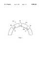
- FIG. 1is a side cross-section view of an acetabular cup which is an aspect of the present invention
- FIG. 2is a side cross-section view of a receiving hole in the acetabular cup of the present invention
- FIG. 3is a side view of a bone screw of the present invention.
- FIG. 4is a side view of a two-piece interlocking coupling element of the present invention.
- FIG. 5is a side cross-section view of a partially assembled screw and interlocking coupling element of the present invention.
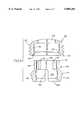
- FIG. 6is a side cross-section view of a fully assembled embodiment of the present invention incorporating, the two-piece interlocking coupling elements as shown in FIG. 4;
- FIG. 7is a side cross-section view of a fully assembled embodiment of the present invention incorporating, a variation of the two-piece interlocking coupling elements as shown in FIG. 4.
- an acetabular cup 100 of the present inventionis shown, respectively, in a side cross-section view, the cross-section being taken in a diametric plane, and a side cross-section of one of the axially tapered holes 110 therein.
- the cup 100may be constructed of any suitably biocompatible material which has the structural strength and durability to withstand the cyclical loading associated with long term fixation in the hip. Materials which would be suitable for such applications include titanium alloys and steels. These materials have enhanced mechanical properties including fatigue endurance and tensile strength, as compared with other materials.
- the cup 100comprises inner and outer surfaces 108 and 103, respectively, said inner surface 108 being concave and the outer surface 103 being convex.
- a second cup shaped insert(not shown) is often affixed within the acetabular cup 100, the inner surface of this second cup being the bearing surface against which the ball head of the femoral post portion of the artificial hip joint rotates.
- a plurality of holes 110having a smooth tapered outer portion 113 and a constant diameter threaded inner portion 111, extend fully through the cup 100.
- Each of the holes 110is ideally suited for receiving therethrough a bone screw for affixing the cup to the bone of the hip socket.
- FIG. 3a screw of a type which is ideally suited for securing the acetabular cup 100 of this invention to the hip of the patient is shown in a side view.
- the screw 120comprises a head portion 122, a neck 124, and a shaft 126.
- the shaft 126is shown as having a tapered shape with a high pitch thread 128. It shall be understood that a variety of shaft designs are interchangeable with the present design. The specific choice of shaft features, such as thread pitch, or shaft diameter to thread diameter ratio, or overall shaft shape, etc. should be made be the physician with respect to the conditions of the patient's bone, however, this invention is compatible with a wide variety of shaft designs.
- the head portion 122 of the screw 120comprises a semi-spherical shape, which has a recess 130 in it. It is understood that the semi-spherical shape is necessarily is a section of a sphere, greater in extent than a hemisphere, and exhibits an external contour which is equidistant from a center point of the head.
- the major cross-section of the semi-spherical head 122includes at least 270 degrees of a circle.
- the recess 130defines a receiving locus for the application of a torque for driving the screw 120 into the bone.
- the specific shape of the recess 122may be chosen to cooperate with any suitable screwdriving tool.
- the recess 130may comprise a slot for a flat-headed screwdriver, a crossed recess for a phillips head screwdriver, a hexagonally shaped hole for receiving an allen wrench, or most preferably, a threading for receiving a correspondingly threaded post. It is further preferable that the recess 130 be co-axial with the general elongate axis of the screw 120, and most particularly with respect to the shaft 126. Having the axes of the recess 130 and the shaft 126 co-linear facilitates the step of inserting the screw 120 into the bone.
- the semi-spherical head portion 122is connected to the shaft 126 at a neck portion 124. While it is preferable that the diameter of the shaft 126 be less than the radius of the semi-spherical head 122, it is also preferable that the neck 124 of the screw 120 be narrower than the widest portion of the shaft 126. This preferable dimension permits the screw to be inserted at a variety of angles while still permitting the specific coupling element to be screwed into the appropriate hole 110 of the cup 100 and remain coupled to the head 122.
- the two portions which form the two-piece interlocking coupling element of the present inventionare shown in a side cross-section view. Phantom lines show the interior structure of the elements along the diametrical cross section.
- the coupling elementcomprises a roughly cylindrical shape having an interior volume 134 in which the semi-spherical head 122 of the screw 120 is disposed.
- the interior volume 134is open at the top 136 of the socket portion 132 and at the bottom thereof 138.
- the lower section 131 of the socket portion 132comprises a set of slots 133 which extend vertically from the bottom 138 of the socket portion 132 to a position above the maximum diameter of the semi-spherical interior volume 134.
- slots 133permit the interior volume to expand and contract in accordance with the application of a radial force thereon.
- the external surface 135 of the lower section 131 of the socket portion 132is tapered such that the narrowest part of the lower section 131 is at the bottom 138.
- the upper section 139 of the socket portion 132has a generally constant diameter, which is less than the diameter at the uppermost position 137 of the taper of the lower section 131.
- a second set of vertical slots 141are provided in this upper section 139 so that it may also expand and contract in accordance with radial forces applied thereto.
- the uppermost end of this upper section 139comprises an outwardly extending annular lip 140.
- the cap portion 142 of the coupling elementcomprises an opening 143 in the bottom thereof, having an inwardly tapered entrance surface conformation 144.
- the taper 144 of the opening 143provides an inwardly directed force which causes the upper section 139 to contract (causes the slots 141 to narrow).
- This tapered entrance 144opens to form an annular lip 145 which is useful for engaging and retaining the annular lip 140 of the upper section 139 of the socket portion 132.
- the interior surface 146 of the cap portionhas a constant diameter, therein permitting the inserted upper section 139 of the socket portion 132 to slide and rotate relative to the cap portion 142.
- the exterior surface of the cap portion 142comprises a threading 147 which is designed to engage the threading 111 in the upper portion of the corresponding hole 110 or 112.
- the cap portion 142comprises an axial hole 148 through which a surgeon may insert a screw driving tool to access the head of the screw which is positioned in the interior volume 134 of the socket portion 132.
- the top 136 of the socket portion 132is inserted into the opening in the cap portion 142 until the annular lip 140 of the socket 132 seats into the cap 142.
- the screw 120is loosely held within the socket 132, which is, in turn, loosely retained within the cap 142.
- FIG. 6in which the fully assembled and inserted screw and coupling element are shown in side cross-section view, in the hole 110 in the cup, the implantation of this embodiment is described.
- the cup 100is positioned in the hip socket, against the bones to which it is to be immobilized.
- a drillis used to pre-form holes into which the bone screws 120 are to be inserted (at the desired angulation).
- the screw 120which has already been coupled with the two-piece interlocking coupling element polyaxially mounted to the semi-spherical head, is is then inserted and driven into the bone by use of the appropriate screw driving tool. As the screw 120 is driven deeper into the bone, the coupling element mounted to the head of the screw begins to enter the hole 110 of the cup 100.
- the tapered exterior surface 135 of the socket portion 132seats against the tapered portion 113 of the hole 110.
- the slot 133 in the bottom of the socket portion 132to narrow, thus causing the interior volume 134 of the socket portion 132 to crush against the head 122 of the screw 120.
- the cap portion 142 of the coupling elementmay then be threadably advanced into the inner portion 111 of the hole 110. As it is advanced, the upper annular lip 140 of the socket portion 132 slides upwardly along the inner surface 146 of the cap 142 until the bottom tapered opening 144 contacts the widened taper position of the socket portion 132. Continued advancement of the cap portion 142 provides further advancement of the socket portion 132 into the tapered portion 113 of the hole 110, thereby increased locking pressure within the interior volume 134 against the head 122.
- the inner surface 146' of the cap portion 142is tapered inwardly in the vertical direction so that the advancement of the cap portion 142 along the threading 111 of the hole 110 causes the annular lip 140 to be compressed inwardly. This causes the slots 141 of the upper section 139 of the socket portion 132 to narrow. This may be utilized to further clamp the interior volume 134 against the head 122 of the screw 120. Once screwed into the cup 100, and locked down, the cap portion 142 of the coupling element and the inner surface 108 of the cup present a flush surface.
Landscapes
- Health & Medical Sciences (AREA)
- Orthopedic Medicine & Surgery (AREA)
- Cardiology (AREA)
- Oral & Maxillofacial Surgery (AREA)
- Transplantation (AREA)
- Engineering & Computer Science (AREA)
- Biomedical Technology (AREA)
- Heart & Thoracic Surgery (AREA)
- Vascular Medicine (AREA)
- Life Sciences & Earth Sciences (AREA)
- Animal Behavior & Ethology (AREA)
- General Health & Medical Sciences (AREA)
- Public Health (AREA)
- Veterinary Medicine (AREA)
- Prostheses (AREA)
- Surgical Instruments (AREA)
Abstract
Description
Claims (6)
Priority Applications (3)
| Application Number | Priority Date | Filing Date | Title |
|---|---|---|---|
| US08/843,972US5888204A (en) | 1996-04-15 | 1997-04-17 | Acetabular cup having capped polyaxial locking screws |
| US09/992,612USRE39089E1 (en) | 1995-04-13 | 2001-11-13 | Polyaxial pedicle screw having a threaded and tapered compression locking mechanism |
| US11/256,914USRE42545E1 (en) | 1995-04-13 | 2005-10-24 | Polyaxial pedicle screw having a threaded and tapered compression locking mechanism |
Applications Claiming Priority (2)
| Application Number | Priority Date | Filing Date | Title |
|---|---|---|---|
| US08/632,560US5725588A (en) | 1995-04-13 | 1996-04-15 | Acetabular cup having polyaxial locking screws |
| US08/843,972US5888204A (en) | 1996-04-15 | 1997-04-17 | Acetabular cup having capped polyaxial locking screws |
Related Parent Applications (1)
| Application Number | Title | Priority Date | Filing Date |
|---|---|---|---|
| US08/632,560Continuation-In-PartUS5725588A (en) | 1995-04-13 | 1996-04-15 | Acetabular cup having polyaxial locking screws |
Related Child Applications (1)
| Application Number | Title | Priority Date | Filing Date |
|---|---|---|---|
| US09/774,915Continuation-In-PartUSRE37665E1 (en) | 1995-04-13 | 2001-01-30 | Polyaxial pedicle screw having a threaded and tapered compression locking mechanism |
Publications (1)
| Publication Number | Publication Date |
|---|---|
| US5888204Atrue US5888204A (en) | 1999-03-30 |
Family
ID=24535999
Family Applications (1)
| Application Number | Title | Priority Date | Filing Date |
|---|---|---|---|
| US08/843,972Expired - LifetimeUS5888204A (en) | 1995-04-13 | 1997-04-17 | Acetabular cup having capped polyaxial locking screws |
Country Status (1)
| Country | Link |
|---|---|
| US (1) | US5888204A (en) |
Cited By (75)
| Publication number | Priority date | Publication date | Assignee | Title |
|---|---|---|---|---|
| US20030105529A1 (en)* | 2001-11-16 | 2003-06-05 | Synder Duane G. | Prosthetic cup assembly having increased assembly congruency |
| US6610097B2 (en) | 2000-03-15 | 2003-08-26 | Depuy Orthopaedics, Inc. | Prosthetic cup assembly which includes components possessing self-locking taper and associated method |
| FR2838329A1 (en)* | 2002-04-15 | 2003-10-17 | Taloco Invest N V | Cotyle structure for treating hip complaints has one or more fixing holes with temporary plugs that can be broken off prior to use |
| US6679883B2 (en) | 2001-10-31 | 2004-01-20 | Ortho Development Corporation | Cervical plate for stabilizing the human spine |
| US20040030339A1 (en)* | 2001-04-20 | 2004-02-12 | Wack Michael A. | Dual locking plate and associated method |
| US20040204717A1 (en)* | 2003-04-09 | 2004-10-14 | Jonathan Fanger | Guide for spinal tools, implants, and devices |
| US20040204712A1 (en)* | 2003-04-09 | 2004-10-14 | Eric Kolb | Bone fixation plates |
| US20040204710A1 (en)* | 2003-04-09 | 2004-10-14 | Tushar Patel | Drill guide and plate inserter |
| US20040236330A1 (en)* | 2003-05-22 | 2004-11-25 | Thomas Purcell | Variable angle spinal screw assembly |
| US20040254579A1 (en)* | 2003-03-20 | 2004-12-16 | Stryker Trauma S.A. | Bone connection device |
| US20050059970A1 (en)* | 2003-09-17 | 2005-03-17 | Eric Kolb | Bone fixation systems |
| EP1520561A1 (en)* | 2003-10-01 | 2005-04-06 | Biomet France | Scapular glenoid cavity prosthesis |
| US20050085915A1 (en)* | 2001-12-04 | 2005-04-21 | Amiram Steinberg | Cushion bearing implants for load bearing applications |
| US20050202371A1 (en)* | 2002-05-23 | 2005-09-15 | Mcguire John | Implants |
| US7001389B1 (en) | 2002-07-05 | 2006-02-21 | Navarro Richard R | Fixed and variable locking fixation assembly |
| US20060190090A1 (en)* | 2005-02-18 | 2006-08-24 | Howmedica Osteonics Corp. | Polyaxial screw for acetabular cup |
| US20060200128A1 (en)* | 2003-04-04 | 2006-09-07 | Richard Mueller | Bone anchor |
| US20060200248A1 (en)* | 2005-03-03 | 2006-09-07 | Laurent Beguin | Prosthesis for the glenoid cavity of the scapula |
| WO2006117674A3 (en)* | 2005-05-02 | 2007-03-01 | Mariasal Invest Nv | Acetabular cup with stem having an inclined portion |
| US20070093133A1 (en)* | 2003-06-11 | 2007-04-26 | Ashton Roger W F | Fixing assembly |
| US20070173945A1 (en)* | 2006-01-20 | 2007-07-26 | Zimmer Technology, Inc. | Shoulder arthroplasty system |
| US7255712B1 (en) | 1997-04-15 | 2007-08-14 | Active Implants Corporation | Bone growth promoting implant |
| US20080033430A1 (en)* | 2003-09-08 | 2008-02-07 | Joseph Ferrante | Orthopaedic Plate and Screw Assembly |
| US20080077142A1 (en)* | 2004-03-26 | 2008-03-27 | Smith & Nephew, Inc. | Methods for treating fractures of the femur and femoral fracture devices |
| US20080133020A1 (en)* | 2006-11-30 | 2008-06-05 | Biomet Manufacturing Corp. | Arthroscopic unicompartmental knee implantation system and related method |
| US20080147121A1 (en)* | 2006-01-27 | 2008-06-19 | Warsaw Orthopedic, Inc. | Multi-Axial Screw Assembly |
| US20080172094A1 (en)* | 2001-12-24 | 2008-07-17 | Synthes (U.S.A) | Device for osteosynthesis |
| US20080177334A1 (en)* | 2007-01-19 | 2008-07-24 | Alexa Medical, Llc | Screw and method of use |
| US20080228281A1 (en)* | 2005-09-16 | 2008-09-18 | Zimmer Gmbh | Insert and Shell of a Joint Ball Receptacle |
| US20080255672A1 (en)* | 2007-04-10 | 2008-10-16 | Warsaw Orthopedic, Inc. | Orthopedic implant |
| US20080281326A1 (en)* | 2007-03-20 | 2008-11-13 | Kohsuke Watanabe | Orthopaedic plate and screw assembly |
| US20080294268A1 (en)* | 2005-11-18 | 2008-11-27 | Zimmer Gmbh | Base Platform for an Artificial Joint |
| US20090069852A1 (en)* | 2007-09-06 | 2009-03-12 | Warsaw Orthopedic, Inc. | Multi-Axial Bone Anchor Assembly |
| US20090187251A1 (en)* | 2002-04-25 | 2009-07-23 | Zimmer Technology, Inc. | Modular bone implant, tools, and method |
| US20090210067A1 (en)* | 2008-02-20 | 2009-08-20 | Biomet Manufacturing Corp. | Acetabular Cup Fixation |
| US20090312803A1 (en)* | 2003-09-29 | 2009-12-17 | Austin Gene E | Bone Plate and Bone Plate Assemblies Including Polyaxial Fasteners |
| US20100094357A1 (en)* | 2008-10-14 | 2010-04-15 | K2M, Inc. | Semi-constrained screw and spinal plate assembly |
| US7722652B2 (en) | 2006-01-27 | 2010-05-25 | Warsaw Orthopedic, Inc. | Pivoting joints for spinal implants including designed resistance to motion and methods of use |
| US20100131073A1 (en)* | 2008-11-24 | 2010-05-27 | Biomet Manufacturing Corp. | Multiple Bearing Acetabular Prosthesis |
| US7736380B2 (en) | 2004-12-21 | 2010-06-15 | Rhausler, Inc. | Cervical plate system |
| US7766947B2 (en) | 2001-10-31 | 2010-08-03 | Ortho Development Corporation | Cervical plate for stabilizing the human spine |
| US20100198272A1 (en)* | 2007-07-20 | 2010-08-05 | Thomas Keyer | Polyaxial bone fixation element |
| US20100241175A1 (en)* | 2009-03-20 | 2010-09-23 | Spinal USA LLC | Pedicle screws and methods of using the same |
| US20100268284A1 (en)* | 2006-04-11 | 2010-10-21 | Bankoski Brian R | Minimally invasive fixation system |
| US7833252B2 (en) | 2006-01-27 | 2010-11-16 | Warsaw Orthopedic, Inc. | Pivoting joints for spinal implants including designed resistance to motion and methods of use |
| US20110035014A1 (en)* | 2006-01-20 | 2011-02-10 | Zimmer Gmbh | Humeral component |
| US7909829B2 (en) | 2003-06-27 | 2011-03-22 | Depuy Spine, Inc. | Tissue retractor and drill guide |
| US7909848B2 (en) | 2003-06-27 | 2011-03-22 | Depuy Spine, Inc. | Tissue retractor and guide device |
| US7935123B2 (en) | 2003-04-09 | 2011-05-03 | Depuy Acromed, Inc. | Drill guide with alignment feature |
| US20110106172A1 (en)* | 2009-11-05 | 2011-05-05 | K2M, Inc. | Semi-constrained bone screw |
| US20110130634A1 (en)* | 2009-05-20 | 2011-06-02 | Synthes Usa, Llc | Patient-mounted retraction |
| US20110160779A1 (en)* | 2008-09-05 | 2011-06-30 | Synthes Usa, Llc | Bone fixation assembly |
| US8308810B2 (en) | 2009-07-14 | 2012-11-13 | Biomet Manufacturing Corp. | Multiple bearing acetabular prosthesis |
| US8382807B2 (en) | 2005-07-25 | 2013-02-26 | Smith & Nephew, Inc. | Systems and methods for using polyaxial plates |
| US8449544B2 (en) | 2009-06-30 | 2013-05-28 | Smith & Nephew, Inc. | Orthopaedic implant and fastener assembly |
| US8535318B2 (en) | 2010-04-23 | 2013-09-17 | DePuy Synthes Products, LLC | Minimally invasive instrument set, devices and related methods |
| US8641770B2 (en) | 2012-01-26 | 2014-02-04 | Aptis Medical, Llc | Prosthesis for the basal joint of the thumb |
| US8808391B2 (en) | 2002-03-26 | 2014-08-19 | T.J. Smith & Nephew, Limited | Hip joint prosthesis |
| US8834469B2 (en) | 2009-06-30 | 2014-09-16 | Smith & Nephew, Inc. | Orthopaedic implant and fastener assembly |
| US8940028B2 (en) | 2005-07-25 | 2015-01-27 | Smith & Nephew, Inc. | Systems and methods for using polyaxial plates |
| US9314274B2 (en) | 2011-05-27 | 2016-04-19 | DePuy Synthes Products, Inc. | Minimally invasive spinal fixation system including vertebral alignment features |
| US9320546B2 (en) | 2008-09-29 | 2016-04-26 | DePuy Synthes Products, Inc. | Polyaxial bottom-loading screw and rod assembly |
| US9326796B2 (en) | 2008-11-03 | 2016-05-03 | DePuy Synthes Products, Inc. | Uni-planer bone fixation assembly |
| US9439681B2 (en) | 2007-07-20 | 2016-09-13 | DePuy Synthes Products, Inc. | Polyaxial bone fixation element |
| US9744046B2 (en) | 2012-02-07 | 2017-08-29 | Biomet Manufacturing, Llc | Locking screw assembly |
| US9848918B2 (en) | 2005-11-21 | 2017-12-26 | DePuy Synthes Products, Inc. | Polyaxial bone anchors with increased angulation |
| US9877839B2 (en)* | 2015-08-25 | 2018-01-30 | Wright Medical Technology, Inc. | Modular talar fixation method and system |
| US9974571B2 (en) | 2008-09-12 | 2018-05-22 | DePuy Synthes Products, Inc. | Spinal stabilizing and guiding fixation system |
| US10105163B2 (en) | 2009-04-15 | 2018-10-23 | DePuy Synthes Products, Inc. | Revision connector for spinal constructs |
| US10149702B2 (en) | 2015-01-12 | 2018-12-11 | Imds Llc | Polyaxial screw and rod system |
| US10390866B2 (en) | 2011-06-15 | 2019-08-27 | Smith & Nephew, Inc. | Variable angle locking implant |
| US10993750B2 (en) | 2015-09-18 | 2021-05-04 | Smith & Nephew, Inc. | Bone plate |
| US11006978B2 (en) | 2009-06-17 | 2021-05-18 | DePuy Synthes Products, Inc. | Revision connector for spinal constructs |
| US11559404B2 (en)* | 2017-02-14 | 2023-01-24 | Onkos Surgical, Inc. | Acetabular surgical implant for segmental pelvic defect and methods of use and manufacture |
| US12440248B2 (en) | 2022-06-28 | 2025-10-14 | DePuy Synthes Products, Inc. | Minimally invasive instrument set, devices, and related methods |
Citations (3)
| Publication number | Priority date | Publication date | Assignee | Title |
|---|---|---|---|---|
| US4936861A (en)* | 1987-10-28 | 1990-06-26 | Sulzer Brothers Limited | Acetabular cup prosthesis |
| US5376125A (en)* | 1991-01-25 | 1994-12-27 | Winkler; Heinz | Hip joint endoprosthesis |
| US5607426A (en)* | 1995-04-13 | 1997-03-04 | Fastenletix, L.L.C. | Threaded polyaxial locking screw plate assembly |
- 1997
- 1997-04-17USUS08/843,972patent/US5888204A/ennot_activeExpired - Lifetime
Patent Citations (3)
| Publication number | Priority date | Publication date | Assignee | Title |
|---|---|---|---|---|
| US4936861A (en)* | 1987-10-28 | 1990-06-26 | Sulzer Brothers Limited | Acetabular cup prosthesis |
| US5376125A (en)* | 1991-01-25 | 1994-12-27 | Winkler; Heinz | Hip joint endoprosthesis |
| US5607426A (en)* | 1995-04-13 | 1997-03-04 | Fastenletix, L.L.C. | Threaded polyaxial locking screw plate assembly |
Cited By (188)
| Publication number | Priority date | Publication date | Assignee | Title |
|---|---|---|---|---|
| US20080039941A1 (en)* | 1997-04-15 | 2008-02-14 | Active Implants Corporation | Bone growth promoting implant |
| US7255712B1 (en) | 1997-04-15 | 2007-08-14 | Active Implants Corporation | Bone growth promoting implant |
| US6610097B2 (en) | 2000-03-15 | 2003-08-26 | Depuy Orthopaedics, Inc. | Prosthetic cup assembly which includes components possessing self-locking taper and associated method |
| US20040030339A1 (en)* | 2001-04-20 | 2004-02-12 | Wack Michael A. | Dual locking plate and associated method |
| US6679883B2 (en) | 2001-10-31 | 2004-01-20 | Ortho Development Corporation | Cervical plate for stabilizing the human spine |
| US7766947B2 (en) | 2001-10-31 | 2010-08-03 | Ortho Development Corporation | Cervical plate for stabilizing the human spine |
| US20030105529A1 (en)* | 2001-11-16 | 2003-06-05 | Synder Duane G. | Prosthetic cup assembly having increased assembly congruency |
| US7326253B2 (en) | 2001-11-16 | 2008-02-05 | Depuy Products, Inc. | Prosthetic cup assembly having increased assembly congruency |
| US20050085915A1 (en)* | 2001-12-04 | 2005-04-21 | Amiram Steinberg | Cushion bearing implants for load bearing applications |
| US7572295B2 (en) | 2001-12-04 | 2009-08-11 | Active Implants Corporation | Cushion bearing implants for load bearing applications |
| EP2145604A1 (en) | 2001-12-04 | 2010-01-20 | Active Implants Corporation | Cushion bearing implants for load bearing applications |
| US8814946B2 (en) | 2001-12-04 | 2014-08-26 | Active Implants Corporation | Cushion bearing implants for load bearing applications |
| US7794482B2 (en) | 2001-12-24 | 2010-09-14 | Synthes Usa, Llc | Device for osteosynthesis |
| US20080172094A1 (en)* | 2001-12-24 | 2008-07-17 | Synthes (U.S.A) | Device for osteosynthesis |
| US8808391B2 (en) | 2002-03-26 | 2014-08-19 | T.J. Smith & Nephew, Limited | Hip joint prosthesis |
| FR2838329A1 (en)* | 2002-04-15 | 2003-10-17 | Taloco Invest N V | Cotyle structure for treating hip complaints has one or more fixing holes with temporary plugs that can be broken off prior to use |
| US20090187251A1 (en)* | 2002-04-25 | 2009-07-23 | Zimmer Technology, Inc. | Modular bone implant, tools, and method |
| US8075628B2 (en) | 2002-04-25 | 2011-12-13 | Zimmer, Inc. | Modular bone implant, tools, and method |
| US7758653B2 (en) | 2002-05-23 | 2010-07-20 | Active Implants Corporation | Implants |
| US20050202371A1 (en)* | 2002-05-23 | 2005-09-15 | Mcguire John | Implants |
| US7001389B1 (en) | 2002-07-05 | 2006-02-21 | Navarro Richard R | Fixed and variable locking fixation assembly |
| US7766911B1 (en) | 2002-07-05 | 2010-08-03 | Theken Spine, Llc | Fixed and variable locking fixation assembly |
| US7780666B1 (en) | 2002-07-05 | 2010-08-24 | Theken Spine, Llc | Fixed and variable locking fixation assembly |
| US7785327B1 (en) | 2002-07-05 | 2010-08-31 | Theken Spine, Llc | Fixed and variable locking fixation assembly |
| US20040254579A1 (en)* | 2003-03-20 | 2004-12-16 | Stryker Trauma S.A. | Bone connection device |
| US20060200128A1 (en)* | 2003-04-04 | 2006-09-07 | Richard Mueller | Bone anchor |
| US7416553B2 (en) | 2003-04-09 | 2008-08-26 | Depuy Acromed, Inc. | Drill guide and plate inserter |
| US7776047B2 (en) | 2003-04-09 | 2010-08-17 | Depuy Spine, Inc. | Guide for spinal tools, implants, and devices |
| US8394107B2 (en) | 2003-04-09 | 2013-03-12 | Depuy Spine, Inc. | Guide for spinal tools, implants, and devices |
| US20040204717A1 (en)* | 2003-04-09 | 2004-10-14 | Jonathan Fanger | Guide for spinal tools, implants, and devices |
| US20040204712A1 (en)* | 2003-04-09 | 2004-10-14 | Eric Kolb | Bone fixation plates |
| US7935123B2 (en) | 2003-04-09 | 2011-05-03 | Depuy Acromed, Inc. | Drill guide with alignment feature |
| US20110015685A1 (en)* | 2003-04-09 | 2011-01-20 | Depuy Spine, Inc. | Guide for spinal tools, implants, and devices |
| US20040204710A1 (en)* | 2003-04-09 | 2004-10-14 | Tushar Patel | Drill guide and plate inserter |
| US20040236330A1 (en)* | 2003-05-22 | 2004-11-25 | Thomas Purcell | Variable angle spinal screw assembly |
| US8636775B2 (en) | 2003-05-22 | 2014-01-28 | Thomas Purcell | Variable angle spinal screw assembly |
| US8298265B2 (en) | 2003-05-22 | 2012-10-30 | Thomas Purcell | Variable angle spinal screw assembly |
| US7377923B2 (en) | 2003-05-22 | 2008-05-27 | Alphatec Spine, Inc. | Variable angle spinal screw assembly |
| US7947083B2 (en)* | 2003-06-11 | 2011-05-24 | T. J. Smith & Nephew Limited | Fixing assembly |
| US20110126403A1 (en)* | 2003-06-11 | 2011-06-02 | Smith & Nephew, Inc. | Fixing assembly |
| US20070093133A1 (en)* | 2003-06-11 | 2007-04-26 | Ashton Roger W F | Fixing assembly |
| US8277514B2 (en) | 2003-06-11 | 2012-10-02 | T. J. Smith & Nephew Limited | Fixing assembly |
| US7909829B2 (en) | 2003-06-27 | 2011-03-22 | Depuy Spine, Inc. | Tissue retractor and drill guide |
| US7909848B2 (en) | 2003-06-27 | 2011-03-22 | Depuy Spine, Inc. | Tissue retractor and guide device |
| US20080188853A1 (en)* | 2003-09-08 | 2008-08-07 | Joseph Ferrante | Orthopaedic implant and fastening assembly |
| US20110060337A1 (en)* | 2003-09-08 | 2011-03-10 | Smith & Nephew, Inc. | Orthopaedic Implant and Fastener Assembly |
| US20090209961A1 (en)* | 2003-09-08 | 2009-08-20 | Smith & Nephew, Inc., A Delaware Corporation | Orthopaedic implant and fastener assembly |
| US8105326B2 (en) | 2003-09-08 | 2012-01-31 | Smith & Nephew, Inc. | Orthopaedic implant and fastener assembly |
| US7883509B2 (en) | 2003-09-08 | 2011-02-08 | Smith & Nephew, Inc. | Orthopaedic implant and screw assembly |
| US8298234B2 (en) | 2003-09-08 | 2012-10-30 | Smith & Nephew, Inc. | Orthopaedic implant and fastener assembly |
| US20080033430A1 (en)* | 2003-09-08 | 2008-02-07 | Joseph Ferrante | Orthopaedic Plate and Screw Assembly |
| US7931652B2 (en) | 2003-09-08 | 2011-04-26 | Smith & Nephew, Inc. | Orthopaedic plate and screw assembly |
| US20110087228A1 (en)* | 2003-09-08 | 2011-04-14 | Smith & Nephew, Inc. | Orthopaedic Plate and Fastener Assembly |
| US8617161B2 (en) | 2003-09-08 | 2013-12-31 | Smith & Nephew, Inc. | Orthopaedic plate and fastener assembly |
| US8187275B2 (en) | 2003-09-08 | 2012-05-29 | Smith & Nephew, Inc. | Orthopaedic implant and fastening assembly |
| US20050059970A1 (en)* | 2003-09-17 | 2005-03-17 | Eric Kolb | Bone fixation systems |
| US20090312803A1 (en)* | 2003-09-29 | 2009-12-17 | Austin Gene E | Bone Plate and Bone Plate Assemblies Including Polyaxial Fasteners |
| US8105367B2 (en) | 2003-09-29 | 2012-01-31 | Smith & Nephew, Inc. | Bone plate and bone plate assemblies including polyaxial fasteners |
| US8992581B2 (en) | 2003-09-29 | 2015-03-31 | Smith & Nephew, Inc. | Bone plate and bone plate assemblies including polyaxial fasteners |
| EP1520561A1 (en)* | 2003-10-01 | 2005-04-06 | Biomet France | Scapular glenoid cavity prosthesis |
| FR2860426A1 (en)* | 2003-10-01 | 2005-04-08 | Biomet Merck France | GLENOID CAVITY PROSTHESIS OF SCAPULA |
| US7972336B2 (en) | 2004-03-26 | 2011-07-05 | Smith & Nephew, Inc. | Methods for treating fractures of the femur and femoral fracture devices |
| US20080077142A1 (en)* | 2004-03-26 | 2008-03-27 | Smith & Nephew, Inc. | Methods for treating fractures of the femur and femoral fracture devices |
| US7736380B2 (en) | 2004-12-21 | 2010-06-15 | Rhausler, Inc. | Cervical plate system |
| US20060190090A1 (en)* | 2005-02-18 | 2006-08-24 | Howmedica Osteonics Corp. | Polyaxial screw for acetabular cup |
| US7316715B2 (en) | 2005-02-18 | 2008-01-08 | Howmedica Osteonics Corp. | Polyaxial screw for acetabular cup |
| US20060200248A1 (en)* | 2005-03-03 | 2006-09-07 | Laurent Beguin | Prosthesis for the glenoid cavity of the scapula |
| WO2006117674A3 (en)* | 2005-05-02 | 2007-03-01 | Mariasal Invest Nv | Acetabular cup with stem having an inclined portion |
| US10092337B2 (en) | 2005-07-25 | 2018-10-09 | Smith & Nephew, Inc. | Systems and methods for using polyaxial plates |
| US11896270B2 (en) | 2005-07-25 | 2024-02-13 | Smith & Nephew, Inc. | Systems and methods for using polyaxial plates |
| US10080598B2 (en) | 2005-07-25 | 2018-09-25 | Smith & Nephew, Inc. | Systems and methods for using polyaxial plates |
| US12343053B2 (en) | 2005-07-25 | 2025-07-01 | Smith & Nephew, Inc. | Systems and methods for using polyaxial plates |
| US8940028B2 (en) | 2005-07-25 | 2015-01-27 | Smith & Nephew, Inc. | Systems and methods for using polyaxial plates |
| US10292741B2 (en) | 2005-07-25 | 2019-05-21 | Smith & Nephew, Inc. | Systems and methods for using polyaxial plates |
| US8888824B2 (en) | 2005-07-25 | 2014-11-18 | Smith & Nephew, Inc. | Systems and methods for using polyaxial plates |
| US10736680B2 (en) | 2005-07-25 | 2020-08-11 | Smith & Nephew, Inc. | Systems and methods for using polyaxial plates |
| US8382807B2 (en) | 2005-07-25 | 2013-02-26 | Smith & Nephew, Inc. | Systems and methods for using polyaxial plates |
| US9795424B2 (en) | 2005-07-25 | 2017-10-24 | Smith & Nephew, Inc. | Systems and methods for using polyaxial plates |
| US10327822B2 (en) | 2005-07-25 | 2019-06-25 | Smith & Nephew, Inc. | Systems and methods for using polyaxial plates |
| US20080228281A1 (en)* | 2005-09-16 | 2008-09-18 | Zimmer Gmbh | Insert and Shell of a Joint Ball Receptacle |
| US8608805B2 (en) | 2005-09-16 | 2013-12-17 | Zimmer Gmbh | Insert and shell of a joint ball receptacle |
| US8690951B2 (en) | 2005-11-18 | 2014-04-08 | Zimmer, Gmbh | Base platform for an artificial joint |
| US20080294268A1 (en)* | 2005-11-18 | 2008-11-27 | Zimmer Gmbh | Base Platform for an Artificial Joint |
| US10595908B2 (en) | 2005-11-21 | 2020-03-24 | DePuy Sythes Products, Inc. | Polaxial bone anchors with increased angulation |
| US9848918B2 (en) | 2005-11-21 | 2017-12-26 | DePuy Synthes Products, Inc. | Polyaxial bone anchors with increased angulation |
| US11432850B2 (en) | 2005-11-21 | 2022-09-06 | DePuy Synthes Products, Inc. | Polyaxial bone anchors with increased angulation |
| US8940054B2 (en) | 2006-01-20 | 2015-01-27 | Zimmer Technology, Inc. | Shoulder arthroplasty system |
| US7854768B2 (en) | 2006-01-20 | 2010-12-21 | Zimmer Technology, Inc. | Shoulder arthroplasty system |
| US9283075B2 (en) | 2006-01-20 | 2016-03-15 | Zimmer, Inc. | Shoulder arthroplasty system |
| US20070173945A1 (en)* | 2006-01-20 | 2007-07-26 | Zimmer Technology, Inc. | Shoulder arthroplasty system |
| US9770334B2 (en) | 2006-01-20 | 2017-09-26 | Zimmer, Inc. | Shoulder arthroplasty system |
| US20100222886A1 (en)* | 2006-01-20 | 2010-09-02 | Zimmer Technology, Inc. | Shoulder arthroplasty system |
| US11298234B2 (en) | 2006-01-20 | 2022-04-12 | Zimmer, Inc. | Shoulder arthroplasty system |
| US20110035014A1 (en)* | 2006-01-20 | 2011-02-10 | Zimmer Gmbh | Humeral component |
| US20110166662A2 (en)* | 2006-01-20 | 2011-07-07 | Zimmer Gmbh | Humeral component |
| US10383735B2 (en) | 2006-01-20 | 2019-08-20 | Zimmer, Inc. | Shoulder arthroplasty system |
| US8057519B2 (en) | 2006-01-27 | 2011-11-15 | Warsaw Orthopedic, Inc. | Multi-axial screw assembly |
| US7833252B2 (en) | 2006-01-27 | 2010-11-16 | Warsaw Orthopedic, Inc. | Pivoting joints for spinal implants including designed resistance to motion and methods of use |
| US7722652B2 (en) | 2006-01-27 | 2010-05-25 | Warsaw Orthopedic, Inc. | Pivoting joints for spinal implants including designed resistance to motion and methods of use |
| US20080147121A1 (en)* | 2006-01-27 | 2008-06-19 | Warsaw Orthopedic, Inc. | Multi-Axial Screw Assembly |
| US9498262B2 (en) | 2006-04-11 | 2016-11-22 | DePuy Synthes Products, Inc. | Minimally invasive fixation system |
| US10441325B2 (en) | 2006-04-11 | 2019-10-15 | DePuy Synthes Products, Inc. | Minimally invasive fixation system |
| US20100268284A1 (en)* | 2006-04-11 | 2010-10-21 | Bankoski Brian R | Minimally invasive fixation system |
| US20080133020A1 (en)* | 2006-11-30 | 2008-06-05 | Biomet Manufacturing Corp. | Arthroscopic unicompartmental knee implantation system and related method |
| US7896923B2 (en)* | 2006-11-30 | 2011-03-01 | Biomet Manufacturing Corp. | Arthroscopic unicompartmental knee implantation system and related method |
| US8317845B2 (en) | 2007-01-19 | 2012-11-27 | Alexa Medical, Llc | Screw and method of use |
| US20080177334A1 (en)* | 2007-01-19 | 2008-07-24 | Alexa Medical, Llc | Screw and method of use |
| US20110238121A1 (en)* | 2007-03-20 | 2011-09-29 | Smith & Nephew, Inc. | Orthopaedic plate and screw assembly |
| US7918853B2 (en) | 2007-03-20 | 2011-04-05 | Smith & Nephew, Inc. | Orthopaedic plate and screw assembly |
| US20080281326A1 (en)* | 2007-03-20 | 2008-11-13 | Kohsuke Watanabe | Orthopaedic plate and screw assembly |
| US8939978B2 (en) | 2007-03-20 | 2015-01-27 | Smith & Nephew, Inc. | Orthopaedic plate and screw assembly |
| US20080255672A1 (en)* | 2007-04-10 | 2008-10-16 | Warsaw Orthopedic, Inc. | Orthopedic implant |
| US9439681B2 (en) | 2007-07-20 | 2016-09-13 | DePuy Synthes Products, Inc. | Polyaxial bone fixation element |
| US11998246B2 (en) | 2007-07-20 | 2024-06-04 | DePuy Synthes Products, Inc. | Polyaxial bone fixation element |
| US10898234B2 (en) | 2007-07-20 | 2021-01-26 | DePuy Synthes Products, Inc. | Polyaxial bone fixation element |
| US11357550B2 (en) | 2007-07-20 | 2022-06-14 | DePuy Synthes Products, Inc. | Polyaxial bone fixation element |
| US8663298B2 (en) | 2007-07-20 | 2014-03-04 | DePuy Synthes Products, LLC | Polyaxial bone fixation element |
| US10136923B2 (en) | 2007-07-20 | 2018-11-27 | DePuy Synthes Products, Inc. | Polyaxial bone fixation element |
| US11819247B2 (en) | 2007-07-20 | 2023-11-21 | DePuy Synthes Products, Inc. | Polyaxial bone fixation element |
| US20100198272A1 (en)* | 2007-07-20 | 2010-08-05 | Thomas Keyer | Polyaxial bone fixation element |
| US20090069852A1 (en)* | 2007-09-06 | 2009-03-12 | Warsaw Orthopedic, Inc. | Multi-Axial Bone Anchor Assembly |
| US8556985B2 (en) | 2008-02-20 | 2013-10-15 | Biomet Manufacturing, Llc | Acetabular cup fixation |
| US9351839B2 (en) | 2008-02-20 | 2016-05-31 | Biomet Manufacturing, Llc | Acetabular cup fixation |
| US20090210067A1 (en)* | 2008-02-20 | 2009-08-20 | Biomet Manufacturing Corp. | Acetabular Cup Fixation |
| US11134992B2 (en) | 2008-09-05 | 2021-10-05 | DePuy Synthes Products, Inc. | Bone fixation assembly |
| US9282998B2 (en) | 2008-09-05 | 2016-03-15 | DePuy Synthes Products, Inc. | Bone fixation assembly |
| US12251137B2 (en) | 2008-09-05 | 2025-03-18 | DePuy Synthes Products, Inc. | Bone fixation assembly |
| US20110160779A1 (en)* | 2008-09-05 | 2011-06-30 | Synthes Usa, Llc | Bone fixation assembly |
| US10357287B2 (en) | 2008-09-05 | 2019-07-23 | DePuy Synthes Products, Inc. | Bone fixation assembly |
| US9872710B2 (en) | 2008-09-05 | 2018-01-23 | DePuy Synthes Products, Inc. | Bone fixation assembly |
| US11812998B2 (en) | 2008-09-05 | 2023-11-14 | DePuy Synthes Products, Inc. | Bone fixation assembly |
| US9974571B2 (en) | 2008-09-12 | 2018-05-22 | DePuy Synthes Products, Inc. | Spinal stabilizing and guiding fixation system |
| US11129648B2 (en) | 2008-09-12 | 2021-09-28 | DePuy Synthes Products, Inc. | Spinal stabilizing and guiding fixation system |
| US11890037B2 (en) | 2008-09-12 | 2024-02-06 | DePuy Synthes Products, Inc. | Spinal stabilizing and guiding fixation system |
| US10154859B2 (en) | 2008-09-29 | 2018-12-18 | DePuy Synthes Products, Inc. | Polyaxial bottom-loading screw and rod assembly |
| US10709479B2 (en) | 2008-09-29 | 2020-07-14 | DePuy Synthes Products, Inc. | Polyaxial bottom-loading screw and rod assembly |
| US9320546B2 (en) | 2008-09-29 | 2016-04-26 | DePuy Synthes Products, Inc. | Polyaxial bottom-loading screw and rod assembly |
| US20100094357A1 (en)* | 2008-10-14 | 2010-04-15 | K2M, Inc. | Semi-constrained screw and spinal plate assembly |
| US8574272B2 (en) | 2008-10-14 | 2013-11-05 | K2M, Inc. | Semi-constrained screw and spinal plate assembly |
| US10405892B2 (en) | 2008-11-03 | 2019-09-10 | DePuy Synthes Products, Inc. | Uni-planer bone fixation assembly |
| US11484348B2 (en) | 2008-11-03 | 2022-11-01 | DePuy Synthes Products, Inc. | Uni-planer bone fixation assembly |
| US9326796B2 (en) | 2008-11-03 | 2016-05-03 | DePuy Synthes Products, Inc. | Uni-planer bone fixation assembly |
| US9445903B2 (en) | 2008-11-24 | 2016-09-20 | Biomet Manufacturing, Llc | Multi-bearing acetabular prosthesis |
| US20100131073A1 (en)* | 2008-11-24 | 2010-05-27 | Biomet Manufacturing Corp. | Multiple Bearing Acetabular Prosthesis |
| US8123815B2 (en) | 2008-11-24 | 2012-02-28 | Biomet Manufacturing Corp. | Multiple bearing acetabular prosthesis |
| US20100241175A1 (en)* | 2009-03-20 | 2010-09-23 | Spinal USA LLC | Pedicle screws and methods of using the same |
| US8882809B2 (en) | 2009-03-20 | 2014-11-11 | Spinal Usa, Inc. | Pedicle screws and methods of using the same |
| US9254151B2 (en) | 2009-03-20 | 2016-02-09 | Spinal Usa, Inc. | Pedicle screws and methods of using the same |
| US8241341B2 (en) | 2009-03-20 | 2012-08-14 | Spinal Usa, Inc. | Pedicle screws and methods of using the same |
| US12064145B2 (en) | 2009-04-15 | 2024-08-20 | DePuy Synthes Products, Inc. | Revision connector for spinal constructs |
| US11020152B2 (en) | 2009-04-15 | 2021-06-01 | DePuy Synthes Products, Inc. | Revision connector for spinal constructs |
| US10105163B2 (en) | 2009-04-15 | 2018-10-23 | DePuy Synthes Products, Inc. | Revision connector for spinal constructs |
| US12349936B2 (en) | 2009-05-20 | 2025-07-08 | DePuy Synthes Products, Inc. | Patient-mounted retraction |
| US10993739B2 (en) | 2009-05-20 | 2021-05-04 | DePuy Synthes Products, Inc. | Patient-mounted retraction |
| US9808281B2 (en) | 2009-05-20 | 2017-11-07 | DePuy Synthes Products, Inc. | Patient-mounted retraction |
| US20110130634A1 (en)* | 2009-05-20 | 2011-06-02 | Synthes Usa, Llc | Patient-mounted retraction |
| US12089877B2 (en) | 2009-06-17 | 2024-09-17 | DePuy Synthes Products, Inc. | Revision connector for spinal constructs |
| US11006978B2 (en) | 2009-06-17 | 2021-05-18 | DePuy Synthes Products, Inc. | Revision connector for spinal constructs |
| US8449544B2 (en) | 2009-06-30 | 2013-05-28 | Smith & Nephew, Inc. | Orthopaedic implant and fastener assembly |
| US8834469B2 (en) | 2009-06-30 | 2014-09-16 | Smith & Nephew, Inc. | Orthopaedic implant and fastener assembly |
| US8308810B2 (en) | 2009-07-14 | 2012-11-13 | Biomet Manufacturing Corp. | Multiple bearing acetabular prosthesis |
| US9445904B2 (en) | 2009-07-14 | 2016-09-20 | Biomet Manufacturing, Llc | Multiple bearing acetabular prosthesis |
| US9095390B2 (en) | 2009-11-05 | 2015-08-04 | K2M, Inc. | Semi-constrained bone screw |
| US20110106172A1 (en)* | 2009-11-05 | 2011-05-05 | K2M, Inc. | Semi-constrained bone screw |
| US8449585B2 (en) | 2009-11-05 | 2013-05-28 | K2M, Inc. | Semi-constrained bone screw |
| US11389213B2 (en) | 2010-04-23 | 2022-07-19 | DePuy Synthes Products, Inc. | Minimally invasive instrument set, devices, and related methods |
| US9402663B2 (en) | 2010-04-23 | 2016-08-02 | DePuy Synthes Products, Inc. | Minimally invasive instrument set, devices and related methods |
| US10888360B2 (en) | 2010-04-23 | 2021-01-12 | DePuy Synthes Products, Inc. | Minimally invasive instrument set, devices, and related methods |
| US8535318B2 (en) | 2010-04-23 | 2013-09-17 | DePuy Synthes Products, LLC | Minimally invasive instrument set, devices and related methods |
| US10098666B2 (en) | 2011-05-27 | 2018-10-16 | DePuy Synthes Products, Inc. | Minimally invasive spinal fixation system including vertebral alignment features |
| US9314274B2 (en) | 2011-05-27 | 2016-04-19 | DePuy Synthes Products, Inc. | Minimally invasive spinal fixation system including vertebral alignment features |
| US10390866B2 (en) | 2011-06-15 | 2019-08-27 | Smith & Nephew, Inc. | Variable angle locking implant |
| US10405901B2 (en) | 2011-06-15 | 2019-09-10 | Smith & Nephew, Inc. | Variable angle locking implant |
| US10448980B2 (en) | 2011-06-15 | 2019-10-22 | Smith & Nephew, Inc. | Variable angle locking implant |
| US12390253B2 (en) | 2011-06-15 | 2025-08-19 | Smith & Nephew, Inc. | Variable angle locking implant |
| WO2013112405A3 (en)* | 2012-01-26 | 2014-10-16 | Aptis Medical, Llc | Prosthesis for the basal joint of the thumb |
| US8641770B2 (en) | 2012-01-26 | 2014-02-04 | Aptis Medical, Llc | Prosthesis for the basal joint of the thumb |
| US9744046B2 (en) | 2012-02-07 | 2017-08-29 | Biomet Manufacturing, Llc | Locking screw assembly |
| US10149702B2 (en) | 2015-01-12 | 2018-12-11 | Imds Llc | Polyaxial screw and rod system |
| US11311386B2 (en) | 2015-08-25 | 2022-04-26 | Wright Medical Technology, Inc. | Modular talar fixation method and system |
| US10327906B2 (en) | 2015-08-25 | 2019-06-25 | Wright Medical Technology, Inc. | Modular talar fixation method and system |
| US9877839B2 (en)* | 2015-08-25 | 2018-01-30 | Wright Medical Technology, Inc. | Modular talar fixation method and system |
| US12350163B2 (en) | 2015-08-25 | 2025-07-08 | Wright Medical Technology, Inc. | Modular talar fixation method and system |
| US11974787B2 (en) | 2015-09-18 | 2024-05-07 | Smith & Nephew, Inc. | Bone plate |
| US11534213B2 (en) | 2015-09-18 | 2022-12-27 | Smith & Nephew, Inc. | Bone plate |
| US10993750B2 (en) | 2015-09-18 | 2021-05-04 | Smith & Nephew, Inc. | Bone plate |
| US11559404B2 (en)* | 2017-02-14 | 2023-01-24 | Onkos Surgical, Inc. | Acetabular surgical implant for segmental pelvic defect and methods of use and manufacture |
| US12440248B2 (en) | 2022-06-28 | 2025-10-14 | DePuy Synthes Products, Inc. | Minimally invasive instrument set, devices, and related methods |
Similar Documents
| Publication | Publication Date | Title |
|---|---|---|
| US5888204A (en) | Acetabular cup having capped polyaxial locking screws | |
| US5725588A (en) | Acetabular cup having polyaxial locking screws | |
| US5314487A (en) | Acetabular prosthesis with anchoring pegs | |
| US12245947B2 (en) | Glenoid implant anchor post | |
| US5226917A (en) | Acetabular prosthesis with anchoring pegs | |
| US5571201A (en) | Prosthetic acetabular cup and method of implant | |
| US6780186B2 (en) | Anterior cervical plate having polyaxial locking screws and sliding coupling elements | |
| US5586984A (en) | Polyaxial locking screw and coupling element assembly for use with rod fixation apparatus | |
| US8753402B2 (en) | Modular humeral head resurfacing system | |
| US20080119895A1 (en) | Locking bone plate with bushing anti-rotation feature | |
| USRE37665E1 (en) | Polyaxial pedicle screw having a threaded and tapered compression locking mechanism | |
| US5554157A (en) | Rod securing polyaxial locking screw and coupling element assembly | |
| CA2717336C (en) | Variable axis locking mechanism for use in orthopedic implants | |
| HK1062260B (en) | A polyaxial locking screw collar and plate assembly |
Legal Events
| Date | Code | Title | Description |
|---|---|---|---|
| AS | Assignment | Owner name:FASTENETIX, LLC, NEW JERSEY Free format text:ASSIGNMENT OF ASSIGNORS INTEREST;ASSIGNORS:RALPH, JAMES D.;TATAR, STEVEN;REEL/FRAME:008710/0084 Effective date:19970414 | |
| STCF | Information on status: patent grant | Free format text:PATENTED CASE | |
| AS | Assignment | Owner name:STRYKER TECHNOLOGIES CORPORATION, MICHIGAN Free format text:ASSIGNMENT OF ASSIGNORS INTEREST;ASSIGNOR:HOWMEDICA INC.;REEL/FRAME:009781/0191 Effective date:19981202 | |
| AS | Assignment | Owner name:BANK OF AMERICA NATIONAL TRUST AND SAVINGS ASSOCIA Free format text:SECURITY INTEREST;ASSIGNORS:STRYKER CORPORATION;STRYKER FAR EAST, INC.;STRYKER INTERNATIONAL INC.;AND OTHERS;REEL/FRAME:009817/0001 Effective date:19981204 Owner name:BANK OF AMERICA NATIONAL TRUST AND SAVINGS ASSOCIA Free format text:SECURITY AGREEMENT;ASSIGNORS:STRYKER CORPORATION;STRYKER FAR EAST, INC.;REEL/FRAME:014137/0212 Effective date:19981204 | |
| AS | Assignment | Owner name:STRYKER CORPORATION, MICHIGAN Free format text:RELEASE OF SECURITY INTEREST;ASSIGNOR:BANK OF AMERICA, N.A. (F/K/A BANK OF AMERICA NATIONAL TRUST AND SAVINGS ASSOCIATION);REEL/FRAME:012539/0557 Effective date:20020124 Owner name:STRYKER FAR EAST, INC., MICHIGAN Free format text:RELEASE OF SECURITY INTEREST;ASSIGNOR:BANK OF AMERICA, N.A. (F/K/A BANK OF AMERICA NATIONAL TRUST AND SAVINGS ASSOCIATION);REEL/FRAME:012539/0557 Effective date:20020124 Owner name:STRYKER INTERNATIONAL, INC., MICHIGAN Free format text:RELEASE OF SECURITY INTEREST;ASSIGNOR:BANK OF AMERICA, N.A. (F/K/A BANK OF AMERICA NATIONAL TRUST AND SAVINGS ASSOCIATION);REEL/FRAME:012539/0557 Effective date:20020124 Owner name:HOWMEDICA OSTEONICS CORPORATION, MICHIGAN Free format text:RELEASE OF SECURITY INTEREST;ASSIGNOR:BANK OF AMERICA, N.A. (F/K/A BANK OF AMERICA NATIONAL TRUST AND SAVINGS ASSOCIATION);REEL/FRAME:012539/0557 Effective date:20020124 Owner name:PHYSIOTHERAPY ASSOCIATES, INC., MICHIGAN Free format text:RELEASE OF SECURITY INTEREST;ASSIGNOR:BANK OF AMERICA, N.A. (F/K/A BANK OF AMERICA NATIONAL TRUST AND SAVINGS ASSOCIATION);REEL/FRAME:012539/0557 Effective date:20020124 Owner name:STRYKER PUERTO RICO INC., MICHIGAN Free format text:RELEASE OF SECURITY INTEREST;ASSIGNOR:BANK OF AMERICA, N.A. (F/K/A BANK OF AMERICA NATIONAL TRUST AND SAVINGS ASSOCIATION);REEL/FRAME:012539/0557 Effective date:20020124 Owner name:STRYKER SALES CORPORATION, MICHIGAN Free format text:RELEASE OF SECURITY INTEREST;ASSIGNOR:BANK OF AMERICA, N.A. (F/K/A BANK OF AMERICA NATIONAL TRUST AND SAVINGS ASSOCIATION);REEL/FRAME:012539/0557 Effective date:20020124 Owner name:STRYKER TECHNOLOGIES CORPORATION, MICHIGAN Free format text:RELEASE OF SECURITY INTEREST;ASSIGNOR:BANK OF AMERICA, N.A. (F/K/A BANK OF AMERICA NATIONAL TRUST AND SAVINGS ASSOCIATION);REEL/FRAME:012539/0557 Effective date:20020124 Owner name:STRYKER FOREIGN HOLDCO, INC., MICHIGAN Free format text:RELEASE OF SECURITY INTEREST;ASSIGNOR:BANK OF AMERICA, N.A. (F/K/A BANK OF AMERICA NATIONAL TRUST AND SAVINGS ASSOCIATION);REEL/FRAME:012539/0557 Effective date:20020124 Owner name:SMD CORPORATION, MICHIGAN Free format text:RELEASE OF SECURITY INTEREST;ASSIGNOR:BANK OF AMERICA, N.A. (F/K/A BANK OF AMERICA NATIONAL TRUST AND SAVINGS ASSOCIATION);REEL/FRAME:012539/0557 Effective date:20020124 Owner name:HOWMEDICAL LEIBINGER, INC., MICHIGAN Free format text:RELEASE OF SECURITY INTEREST;ASSIGNOR:BANK OF AMERICA, N.A. (F/K/A BANK OF AMERICA NATIONAL TRUST AND SAVINGS ASSOCIATION);REEL/FRAME:012539/0557 Effective date:20020124 | |
| FPAY | Fee payment | Year of fee payment:4 | |
| FEPP | Fee payment procedure | Free format text:PAYOR NUMBER ASSIGNED (ORIGINAL EVENT CODE: ASPN); ENTITY STATUS OF PATENT OWNER: LARGE ENTITY | |
| FPAY | Fee payment | Year of fee payment:8 | |
| AS | Assignment | Owner name:MEDTRONIC SOFAMOR DANEK, INC., TENNESSEE Free format text:ASSIGNMENT OF ASSIGNORS INTEREST;ASSIGNOR:FASTENETIX, LLC;REEL/FRAME:022732/0435 Effective date:20080928 | |
| AS | Assignment | Owner name:WARSAW ORTHOPEDIC, INC., INDIANA Free format text:ASSIGNMENT OF ASSIGNORS INTEREST;ASSIGNOR:MEDTRONIC SOFAMOR DANEK, INC.;REEL/FRAME:022773/0631 Effective date:20090529 | |
| FPAY | Fee payment | Year of fee payment:12 |