US5888087A - One-handed dock for a portable data collection terminal - Google Patents
One-handed dock for a portable data collection terminalDownload PDFInfo
- Publication number
- US5888087A US5888087AUS08/772,538US77253896AUS5888087AUS 5888087 AUS5888087 AUS 5888087AUS 77253896 AUS77253896 AUS 77253896AUS 5888087 AUS5888087 AUS 5888087A
- Authority
- US
- United States
- Prior art keywords
- data collection
- collection terminal
- terminal
- docking
- scanner
- Prior art date
- Legal status (The legal status is an assumption and is not a legal conclusion. Google has not performed a legal analysis and makes no representation as to the accuracy of the status listed.)
- Expired - Fee Related
Links
Images


Classifications
- B—PERFORMING OPERATIONS; TRANSPORTING
- B60—VEHICLES IN GENERAL
- B60R—VEHICLES, VEHICLE FITTINGS, OR VEHICLE PARTS, NOT OTHERWISE PROVIDED FOR
- B60R16/00—Electric or fluid circuits specially adapted for vehicles and not otherwise provided for; Arrangement of elements of electric or fluid circuits specially adapted for vehicles and not otherwise provided for
- B60R16/02—Electric or fluid circuits specially adapted for vehicles and not otherwise provided for; Arrangement of elements of electric or fluid circuits specially adapted for vehicles and not otherwise provided for electric constitutive elements
- B60R16/023—Electric or fluid circuits specially adapted for vehicles and not otherwise provided for; Arrangement of elements of electric or fluid circuits specially adapted for vehicles and not otherwise provided for electric constitutive elements for transmission of signals between vehicle parts or subsystems
- B60R16/0231—Circuits relating to the driving or the functioning of the vehicle
- G—PHYSICS
- G06—COMPUTING OR CALCULATING; COUNTING
- G06F—ELECTRIC DIGITAL DATA PROCESSING
- G06F1/00—Details not covered by groups G06F3/00 - G06F13/00 and G06F21/00
- G06F1/16—Constructional details or arrangements
- G06F1/1613—Constructional details or arrangements for portable computers
- G06F1/1626—Constructional details or arrangements for portable computers with a single-body enclosure integrating a flat display, e.g. Personal Digital Assistants [PDAs]
- G—PHYSICS
- G06—COMPUTING OR CALCULATING; COUNTING
- G06F—ELECTRIC DIGITAL DATA PROCESSING
- G06F1/00—Details not covered by groups G06F3/00 - G06F13/00 and G06F21/00
- G06F1/16—Constructional details or arrangements
- G06F1/1613—Constructional details or arrangements for portable computers
- G06F1/1632—External expansion units, e.g. docking stations
- G—PHYSICS
- G06—COMPUTING OR CALCULATING; COUNTING
- G06F—ELECTRIC DIGITAL DATA PROCESSING
- G06F1/00—Details not covered by groups G06F3/00 - G06F13/00 and G06F21/00
- G06F1/26—Power supply means, e.g. regulation thereof
- G06F1/28—Supervision thereof, e.g. detecting power-supply failure by out of limits supervision
- G—PHYSICS
- G06—COMPUTING OR CALCULATING; COUNTING
- G06F—ELECTRIC DIGITAL DATA PROCESSING
- G06F1/00—Details not covered by groups G06F3/00 - G06F13/00 and G06F21/00
- G06F1/26—Power supply means, e.g. regulation thereof
- G06F1/32—Means for saving power
- G06F1/3203—Power management, i.e. event-based initiation of a power-saving mode
- G—PHYSICS
- G06—COMPUTING OR CALCULATING; COUNTING
- G06K—GRAPHICAL DATA READING; PRESENTATION OF DATA; RECORD CARRIERS; HANDLING RECORD CARRIERS
- G06K17/00—Methods or arrangements for effecting co-operative working between equipments covered by two or more of main groups G06K1/00 - G06K15/00, e.g. automatic card files incorporating conveying and reading operations
- G06K17/0022—Methods or arrangements for effecting co-operative working between equipments covered by two or more of main groups G06K1/00 - G06K15/00, e.g. automatic card files incorporating conveying and reading operations arrangements or provisions for transferring data to distant stations, e.g. from a sensing device
- G—PHYSICS
- G06—COMPUTING OR CALCULATING; COUNTING
- G06K—GRAPHICAL DATA READING; PRESENTATION OF DATA; RECORD CARRIERS; HANDLING RECORD CARRIERS
- G06K7/00—Methods or arrangements for sensing record carriers, e.g. for reading patterns
- G06K7/10—Methods or arrangements for sensing record carriers, e.g. for reading patterns by electromagnetic radiation, e.g. optical sensing; by corpuscular radiation
- G06K7/10544—Methods or arrangements for sensing record carriers, e.g. for reading patterns by electromagnetic radiation, e.g. optical sensing; by corpuscular radiation by scanning of the records by radiation in the optical part of the electromagnetic spectrum
- G06K7/10554—Moving beam scanning
- G06K7/10564—Light sources
- G06K7/10574—Multiple sources
- G—PHYSICS
- G06—COMPUTING OR CALCULATING; COUNTING
- G06K—GRAPHICAL DATA READING; PRESENTATION OF DATA; RECORD CARRIERS; HANDLING RECORD CARRIERS
- G06K7/00—Methods or arrangements for sensing record carriers, e.g. for reading patterns
- G06K7/10—Methods or arrangements for sensing record carriers, e.g. for reading patterns by electromagnetic radiation, e.g. optical sensing; by corpuscular radiation
- G06K7/10544—Methods or arrangements for sensing record carriers, e.g. for reading patterns by electromagnetic radiation, e.g. optical sensing; by corpuscular radiation by scanning of the records by radiation in the optical part of the electromagnetic spectrum
- G06K7/10554—Moving beam scanning
- G06K7/10564—Light sources
- G06K7/10584—Source control
- G—PHYSICS
- G06—COMPUTING OR CALCULATING; COUNTING
- G06K—GRAPHICAL DATA READING; PRESENTATION OF DATA; RECORD CARRIERS; HANDLING RECORD CARRIERS
- G06K7/00—Methods or arrangements for sensing record carriers, e.g. for reading patterns
- G06K7/10—Methods or arrangements for sensing record carriers, e.g. for reading patterns by electromagnetic radiation, e.g. optical sensing; by corpuscular radiation
- G06K7/10544—Methods or arrangements for sensing record carriers, e.g. for reading patterns by electromagnetic radiation, e.g. optical sensing; by corpuscular radiation by scanning of the records by radiation in the optical part of the electromagnetic spectrum
- G06K7/10554—Moving beam scanning
- G06K7/10594—Beam path
- G06K7/10683—Arrangement of fixed elements
- G06K7/10702—Particularities of propagating elements, e.g. lenses, mirrors
- G—PHYSICS
- G06—COMPUTING OR CALCULATING; COUNTING
- G06K—GRAPHICAL DATA READING; PRESENTATION OF DATA; RECORD CARRIERS; HANDLING RECORD CARRIERS
- G06K7/00—Methods or arrangements for sensing record carriers, e.g. for reading patterns
- G06K7/10—Methods or arrangements for sensing record carriers, e.g. for reading patterns by electromagnetic radiation, e.g. optical sensing; by corpuscular radiation
- G06K7/10544—Methods or arrangements for sensing record carriers, e.g. for reading patterns by electromagnetic radiation, e.g. optical sensing; by corpuscular radiation by scanning of the records by radiation in the optical part of the electromagnetic spectrum
- G06K7/10712—Fixed beam scanning
- G06K7/10722—Photodetector array or CCD scanning
- G06K7/10732—Light sources
- G—PHYSICS
- G06—COMPUTING OR CALCULATING; COUNTING
- G06K—GRAPHICAL DATA READING; PRESENTATION OF DATA; RECORD CARRIERS; HANDLING RECORD CARRIERS
- G06K7/00—Methods or arrangements for sensing record carriers, e.g. for reading patterns
- G06K7/10—Methods or arrangements for sensing record carriers, e.g. for reading patterns by electromagnetic radiation, e.g. optical sensing; by corpuscular radiation
- G06K7/10544—Methods or arrangements for sensing record carriers, e.g. for reading patterns by electromagnetic radiation, e.g. optical sensing; by corpuscular radiation by scanning of the records by radiation in the optical part of the electromagnetic spectrum
- G06K7/10792—Special measures in relation to the object to be scanned
- G06K7/10801—Multidistance reading
- G06K7/10811—Focalisation
- G—PHYSICS
- G06—COMPUTING OR CALCULATING; COUNTING
- G06K—GRAPHICAL DATA READING; PRESENTATION OF DATA; RECORD CARRIERS; HANDLING RECORD CARRIERS
- G06K7/00—Methods or arrangements for sensing record carriers, e.g. for reading patterns
- G06K7/10—Methods or arrangements for sensing record carriers, e.g. for reading patterns by electromagnetic radiation, e.g. optical sensing; by corpuscular radiation
- G06K7/10544—Methods or arrangements for sensing record carriers, e.g. for reading patterns by electromagnetic radiation, e.g. optical sensing; by corpuscular radiation by scanning of the records by radiation in the optical part of the electromagnetic spectrum
- G06K7/10821—Methods or arrangements for sensing record carriers, e.g. for reading patterns by electromagnetic radiation, e.g. optical sensing; by corpuscular radiation by scanning of the records by radiation in the optical part of the electromagnetic spectrum further details of bar or optical code scanning devices
- G06K7/10841—Particularities of the light-sensitive elements
- G—PHYSICS
- G06—COMPUTING OR CALCULATING; COUNTING
- G06K—GRAPHICAL DATA READING; PRESENTATION OF DATA; RECORD CARRIERS; HANDLING RECORD CARRIERS
- G06K7/00—Methods or arrangements for sensing record carriers, e.g. for reading patterns
- G06K7/10—Methods or arrangements for sensing record carriers, e.g. for reading patterns by electromagnetic radiation, e.g. optical sensing; by corpuscular radiation
- G06K7/10544—Methods or arrangements for sensing record carriers, e.g. for reading patterns by electromagnetic radiation, e.g. optical sensing; by corpuscular radiation by scanning of the records by radiation in the optical part of the electromagnetic spectrum
- G06K7/10821—Methods or arrangements for sensing record carriers, e.g. for reading patterns by electromagnetic radiation, e.g. optical sensing; by corpuscular radiation by scanning of the records by radiation in the optical part of the electromagnetic spectrum further details of bar or optical code scanning devices
- G06K7/10851—Circuits for pulse shaping, amplifying, eliminating noise signals, checking the function of the sensing device
- G—PHYSICS
- G06—COMPUTING OR CALCULATING; COUNTING
- G06K—GRAPHICAL DATA READING; PRESENTATION OF DATA; RECORD CARRIERS; HANDLING RECORD CARRIERS
- G06K7/00—Methods or arrangements for sensing record carriers, e.g. for reading patterns
- G06K7/10—Methods or arrangements for sensing record carriers, e.g. for reading patterns by electromagnetic radiation, e.g. optical sensing; by corpuscular radiation
- G06K7/10544—Methods or arrangements for sensing record carriers, e.g. for reading patterns by electromagnetic radiation, e.g. optical sensing; by corpuscular radiation by scanning of the records by radiation in the optical part of the electromagnetic spectrum
- G06K7/10821—Methods or arrangements for sensing record carriers, e.g. for reading patterns by electromagnetic radiation, e.g. optical sensing; by corpuscular radiation by scanning of the records by radiation in the optical part of the electromagnetic spectrum further details of bar or optical code scanning devices
- G06K7/10881—Methods or arrangements for sensing record carriers, e.g. for reading patterns by electromagnetic radiation, e.g. optical sensing; by corpuscular radiation by scanning of the records by radiation in the optical part of the electromagnetic spectrum further details of bar or optical code scanning devices constructional details of hand-held scanners
- G—PHYSICS
- G06—COMPUTING OR CALCULATING; COUNTING
- G06K—GRAPHICAL DATA READING; PRESENTATION OF DATA; RECORD CARRIERS; HANDLING RECORD CARRIERS
- G06K7/00—Methods or arrangements for sensing record carriers, e.g. for reading patterns
- G06K7/10—Methods or arrangements for sensing record carriers, e.g. for reading patterns by electromagnetic radiation, e.g. optical sensing; by corpuscular radiation
- G06K7/12—Methods or arrangements for sensing record carriers, e.g. for reading patterns by electromagnetic radiation, e.g. optical sensing; by corpuscular radiation using a selected wavelength, e.g. to sense red marks and ignore blue marks
- G—PHYSICS
- G07—CHECKING-DEVICES
- G07C—TIME OR ATTENDANCE REGISTERS; REGISTERING OR INDICATING THE WORKING OF MACHINES; GENERATING RANDOM NUMBERS; VOTING OR LOTTERY APPARATUS; ARRANGEMENTS, SYSTEMS OR APPARATUS FOR CHECKING NOT PROVIDED FOR ELSEWHERE
- G07C5/00—Registering or indicating the working of vehicles
- G07C5/08—Registering or indicating performance data other than driving, working, idle, or waiting time, with or without registering driving, working, idle or waiting time
- G07C5/0808—Diagnosing performance data
- G—PHYSICS
- G07—CHECKING-DEVICES
- G07C—TIME OR ATTENDANCE REGISTERS; REGISTERING OR INDICATING THE WORKING OF MACHINES; GENERATING RANDOM NUMBERS; VOTING OR LOTTERY APPARATUS; ARRANGEMENTS, SYSTEMS OR APPARATUS FOR CHECKING NOT PROVIDED FOR ELSEWHERE
- G07C5/00—Registering or indicating the working of vehicles
- G07C5/08—Registering or indicating performance data other than driving, working, idle, or waiting time, with or without registering driving, working, idle or waiting time
- G07C5/0841—Registering performance data
- G07C5/085—Registering performance data using electronic data carriers
- G07C5/0858—Registering performance data using electronic data carriers wherein the data carrier is removable
- H—ELECTRICITY
- H01—ELECTRIC ELEMENTS
- H01Q—ANTENNAS, i.e. RADIO AERIALS
- H01Q1/00—Details of, or arrangements associated with, antennas
- H01Q1/50—Structural association of antennas with earthing switches, lead-in devices or lightning protectors
- H—ELECTRICITY
- H01—ELECTRIC ELEMENTS
- H01Q—ANTENNAS, i.e. RADIO AERIALS
- H01Q1/00—Details of, or arrangements associated with, antennas
- H01Q1/52—Means for reducing coupling between antennas; Means for reducing coupling between an antenna and another structure
- H01Q1/526—Electromagnetic shields
- H—ELECTRICITY
- H04—ELECTRIC COMMUNICATION TECHNIQUE
- H04B—TRANSMISSION
- H04B1/00—Details of transmission systems, not covered by a single one of groups H04B3/00 - H04B13/00; Details of transmission systems not characterised by the medium used for transmission
- H04B1/38—Transceivers, i.e. devices in which transmitter and receiver form a structural unit and in which at least one part is used for functions of transmitting and receiving
- H04B1/3827—Portable transceivers
- H04B1/3877—Arrangements for enabling portable transceivers to be used in a fixed position, e.g. cradles or boosters
- H—ELECTRICITY
- H04—ELECTRIC COMMUNICATION TECHNIQUE
- H04L—TRANSMISSION OF DIGITAL INFORMATION, e.g. TELEGRAPHIC COMMUNICATION
- H04L1/00—Arrangements for detecting or preventing errors in the information received
- H04L1/0001—Systems modifying transmission characteristics according to link quality, e.g. power backoff
- H04L1/0023—Systems modifying transmission characteristics according to link quality, e.g. power backoff characterised by the signalling
- H04L1/0025—Transmission of mode-switching indication
- H—ELECTRICITY
- H04—ELECTRIC COMMUNICATION TECHNIQUE
- H04L—TRANSMISSION OF DIGITAL INFORMATION, e.g. TELEGRAPHIC COMMUNICATION
- H04L1/00—Arrangements for detecting or preventing errors in the information received
- H04L1/0001—Systems modifying transmission characteristics according to link quality, e.g. power backoff
- H04L1/0023—Systems modifying transmission characteristics according to link quality, e.g. power backoff characterised by the signalling
- H04L1/0032—Without explicit signalling
- H—ELECTRICITY
- H04—ELECTRIC COMMUNICATION TECHNIQUE
- H04L—TRANSMISSION OF DIGITAL INFORMATION, e.g. TELEGRAPHIC COMMUNICATION
- H04L1/00—Arrangements for detecting or preventing errors in the information received
- H04L1/12—Arrangements for detecting or preventing errors in the information received by using return channel
- H04L1/16—Arrangements for detecting or preventing errors in the information received by using return channel in which the return channel carries supervisory signals, e.g. repetition request signals
- H04L1/1607—Details of the supervisory signal
- H04L1/1671—Details of the supervisory signal the supervisory signal being transmitted together with control information
- H—ELECTRICITY
- H04—ELECTRIC COMMUNICATION TECHNIQUE
- H04L—TRANSMISSION OF DIGITAL INFORMATION, e.g. TELEGRAPHIC COMMUNICATION
- H04L1/00—Arrangements for detecting or preventing errors in the information received
- H04L1/12—Arrangements for detecting or preventing errors in the information received by using return channel
- H04L1/16—Arrangements for detecting or preventing errors in the information received by using return channel in which the return channel carries supervisory signals, e.g. repetition request signals
- H04L1/1607—Details of the supervisory signal
- H04L1/1685—Details of the supervisory signal the supervisory signal being transmitted in response to a specific request, e.g. to a polling signal
- H—ELECTRICITY
- H04—ELECTRIC COMMUNICATION TECHNIQUE
- H04M—TELEPHONIC COMMUNICATION
- H04M1/00—Substation equipment, e.g. for use by subscribers
- H04M1/02—Constructional features of telephone sets
- H04M1/04—Supports for telephone transmitters or receivers
- B—PERFORMING OPERATIONS; TRANSPORTING
- B60—VEHICLES IN GENERAL
- B60R—VEHICLES, VEHICLE FITTINGS, OR VEHICLE PARTS, NOT OTHERWISE PROVIDED FOR
- B60R16/00—Electric or fluid circuits specially adapted for vehicles and not otherwise provided for; Arrangement of elements of electric or fluid circuits specially adapted for vehicles and not otherwise provided for
- B60R16/02—Electric or fluid circuits specially adapted for vehicles and not otherwise provided for; Arrangement of elements of electric or fluid circuits specially adapted for vehicles and not otherwise provided for electric constitutive elements
- B60R16/03—Electric or fluid circuits specially adapted for vehicles and not otherwise provided for; Arrangement of elements of electric or fluid circuits specially adapted for vehicles and not otherwise provided for electric constitutive elements for supply of electrical power to vehicle subsystems or for
- B60R16/0315—Electric or fluid circuits specially adapted for vehicles and not otherwise provided for; Arrangement of elements of electric or fluid circuits specially adapted for vehicles and not otherwise provided for electric constitutive elements for supply of electrical power to vehicle subsystems or for using multiplexing techniques
- H—ELECTRICITY
- H04—ELECTRIC COMMUNICATION TECHNIQUE
- H04B—TRANSMISSION
- H04B1/00—Details of transmission systems, not covered by a single one of groups H04B3/00 - H04B13/00; Details of transmission systems not characterised by the medium used for transmission
- H04B1/38—Transceivers, i.e. devices in which transmitter and receiver form a structural unit and in which at least one part is used for functions of transmitting and receiving
- H04B2001/3894—Waterproofing of transmission device
- H—ELECTRICITY
- H04—ELECTRIC COMMUNICATION TECHNIQUE
- H04M—TELEPHONIC COMMUNICATION
- H04M7/00—Arrangements for interconnection between switching centres
- H04M7/006—Networks other than PSTN/ISDN providing telephone service, e.g. Voice over Internet Protocol (VoIP), including next generation networks with a packet-switched transport layer
- H—ELECTRICITY
- H04—ELECTRIC COMMUNICATION TECHNIQUE
- H04W—WIRELESS COMMUNICATION NETWORKS
- H04W88/00—Devices specially adapted for wireless communication networks, e.g. terminals, base stations or access point devices
- H04W88/02—Terminal devices
- H—ELECTRICITY
- H05—ELECTRIC TECHNIQUES NOT OTHERWISE PROVIDED FOR
- H05K—PRINTED CIRCUITS; CASINGS OR CONSTRUCTIONAL DETAILS OF ELECTRIC APPARATUS; MANUFACTURE OF ASSEMBLAGES OF ELECTRICAL COMPONENTS
- H05K1/00—Printed circuits
- H05K1/02—Details
- H05K1/0213—Electrical arrangements not otherwise provided for
- H05K1/0216—Reduction of cross-talk, noise or electromagnetic interference
- H05K1/023—Reduction of cross-talk, noise or electromagnetic interference using auxiliary mounted passive components or auxiliary substances
- H05K1/0233—Filters, inductors or a magnetic substance
- Y—GENERAL TAGGING OF NEW TECHNOLOGICAL DEVELOPMENTS; GENERAL TAGGING OF CROSS-SECTIONAL TECHNOLOGIES SPANNING OVER SEVERAL SECTIONS OF THE IPC; TECHNICAL SUBJECTS COVERED BY FORMER USPC CROSS-REFERENCE ART COLLECTIONS [XRACs] AND DIGESTS
- Y10—TECHNICAL SUBJECTS COVERED BY FORMER USPC
- Y10S—TECHNICAL SUBJECTS COVERED BY FORMER USPC CROSS-REFERENCE ART COLLECTIONS [XRACs] AND DIGESTS
- Y10S439/00—Electrical connectors
- Y10S439/929—Connecting base plate or shelf type holder
Definitions
- This inventionrelates generally to data processing systems and, more particularly, to docking apparatus which removably receives and retains portable data collection terminals, including communications and power terminals, which become coupled to such a portable data collection terminal upon insertion of the portable data collection terminals into the docking apparatus.
- This inventionalso relates generally to apparatus for, and methods of, retaining a data terminal within the docking apparatus and to apparatus for and methods of establishing and maintaining communicative contact with respective communications and power terminals within the docking apparatus.
- Hand-held, portable data collection terminalsare well known as practical workstations which operators may readily port to various work sites and collect business transaction or inventory data at such work sites.
- the data collection terminalsare therefore essential elements of many business systems, providing the ability to remotely update central processing units of these systems.
- Communication between the portable data collection terminals and the central data processing unitmay be provided on a continuous basis, such as by RF data transceivers or other suitable wireless communications links.
- batch data transfer from the data collection terminals to the respective information systemsmay be more practical and may be the preferred method of transfer.
- Portable data collection terminalsare typically powered by self-contained power sources, such as rechargeable batteries for example.
- the sizes or capacities of batteriesare desirably chosen to permit each respective, portable data collection terminal to operate throughout a normal workday.
- the data collection terminalmay be inserted into a docking device, sometimes referred to as a terminal dock.
- a docking devicesometimes referred to as a terminal dock.
- the power source of the inserted data collection terminalbecomes coupled to a battery recharging circuit. Recharging periods may be efficiently used by transferring collected data from the data collection terminal to a central data processing unit of a respective business system and by updating the data collection terminal with data and instructions for subsequent use as the batteries of the data collection terminal are being recharged.
- a set of merchandise identification numbers and related instruction informationmay be transferred to the data collection terminal during the recharging period.
- an operatormay be directed by such transferred instructions to collect inventory data on the respective items of merchandise based on the specific merchandise identification numbers or codes which had been pre-loaded and which may appear in sequence as the desired inventory information is being collected.
- the data collection terminalmay inform the operator that the task is completed, and to return the data collection terminal to a docking device for a data transfer of the collected inventory information to the central processing unit.
- a docking deviceis generally regarded to be a most desirable, if not necessary, complement for a portable data collection terminal.
- Usefulness of data collection terminalscan be enhanced with increased accessibility to docking devices, particularly docking devices that are more facilitating by providing positive data collection terminal locking devices and ready, one-handed and effortless removal and reinsertion of data collection terminals from and into such docking devices.
- a one-handed end-insertion docking device for a portable data collection terminalcomprises a docking channel which has an insertion opening at an insertion portion thereof
- the docking channelhas a base surface along the length thereof and retention caps longitudinally of the docking device bounding a terminal access opening opposite the base surface of the docking channel.
- a plurality of spring contactsare disposed at a docking seat at a retention end opposite the insertion end.
- the spring contactsare yieldably disposed in the insertion path of a data collection terminal inserted into the docking device. Upon insertion of a data collection terminal longitudinally of the insertion path toward the docking seat, the spring contacts yieldably engage complementary surface contacts on the data collection terminal.
- a retention pawl mechanismincludes at least one retention prong which is biased with a bias force toward an inserted data collection terminal to engage and positively latch such a data collection terminal so inserted in a retention position against the docking seat and in a direction away from engagement with the spring contacts.
- the positive locking or latching featurewhich biases a retained, inserted data collection terminal into a defmed position away from spring contacts of the docking device, hence into a position at which spring contact forces are relatively low, may appear on first glance undesirable.
- any vibrational movement of the data collection terminalsuch as may be caused by shock or vibration in an industrial environment, for example when the docking device is mounted on board of a vehicle, is found to increase the contact force.
- a chance of an undesirable contact bounce, or even a temporary decoupling of complementary contact surfacesis substantially minimized if not avoided, even under severe vibratory conditions.
- the retention pawl mechanismmay comprise at least one retention pawl supporting the retention prong at one end thereof
- the retention prongwould be oriented to engage and retain an inserted data collection terminal.
- the other end of the pawlmay be mounted in accordance herewith to a co-pivotal pivot shaft.
- a releaseis also co-pivotally mounted to the pivot shaft and extends from the pivot shaft over a length which exceeds the length of the pawl to move the retention prong out of a retention position with a lesser force than a bias force against an inserted data collection terminal.
- the docking seatincludes a seat base which is movably mounted to move longitudinally of the docking channel in a direction toward and away from the insertion portion.
- the seat baseis spring biased toward the insertion portion and into the insertion path of a data collection terminal being inserted into the insertion portion of the docking channel.
- a data collection terminalupon being inserted into the docking channel, would be inserted with an insertion force which overcomes the spring bias to which the seat base is subjected to move the seat base in a direction away from the insertion end until the pawl engages the data collection terminal and retains the data collection terminal in the terminal docking device.
- Insertion friction between the data collection terminal and the end-insertion docking devicemay be minimized by the guides having the shape of spherical and cylindrical surfaces whereby minimal contacts, such as point or line contacts, are established with edges of a data collection terminal being inserted into the docking channel.
- the guidesin accordance with the invention, would be disposed adjacent the base surface of the docking channel to bias a data collection terminal in contact therewith toward the retaining caps of the docking channel.
- the dock for a portable data collection terminalmay optionally include a bracket for receiving a scanner connected to the portable data collection terminal wherein the scanner inserted into the bracket, as well as the controls of the data collection terminal inserted into the dock, remain accessible to a user.
- the principal objects and advantages of the present inventioninclude: to provide a terminal dock that facilitates ready one-handed insertion and removal of a data collection terminal into and from the terminal dock; to provide such a terminal dock that provides electrical and signal contact connections with a data collection terminal inserted therein such that there is minimal tendency for the connections to separate under severe shock or vibratory conditions; to provide such a terminal dock that may temporarily hold a data collection terminal without communicative or electrical connections and from which a data collection terminal may be removed without being unlocked from a positive retention position in the terminal dock; to provide such a terminal dock that retains a data collection terminal within a receiving cradle of the terminal dock by a positive retaining lock, to provide such a terminal dock having a terminal release mechanism that, upon activation, urges the data collection terminal out of electrical and communicative engagement with terminals of the terminal dock to prevent inadvertent selective engagement of such contacts; to provide such a terminal dock that includes a bracket for receiving a scanner operably connected to the data collection terminal as the data collection terminal is received by
- FIG. 1is a perspective view of a one-handed dock for a portable data collection terminal, showing a data collection terminal inserted therein, according to the present invention
- FIG. 2is a side elevational view of the one-handed dock for a portable data collection terminal, showing a swivel or pivot mounting arrangement thereof;
- FIG. 3is an enlarged top plan view of the one-handed dock for a portable data collection terminal
- FIG. 4is an enlarged and fragmentary, end elevational view of the one-handed dock for a portable data collection terminal, taken along line 4--4 of FIG. 3, with portions cut away to reveal details thereof;
- FIG. 5is an enlarged and exploded view of the one-handed dock for a portable data collection terminal, showing a cradle portion thereof;
- FIG. 6is a simplified and partially sectioned side elevational view of a data collection terminal of a type which may complementarily be inserted into and retained by the one-handed dock for a portable data collection terminal;
- FIG. 7is a fragmentary bottom plan view of the data collection terminal shown in FIG. 6, taken along line 7--7 of FIG. 6;
- FIG. 8is a further enlarged and fragmentary side elevational view of the one-handed dock for a portable data collection terminal, taken along line 8--8 of FIG. 3, with portions cut away to reveal details thereof;
- FIG. 9is a further enlarged view of an assemblage of elements of a pivot shaft assembly of the one-handed dock for a portable data collection terminal;
- FIG. 10is a further enlarged, cross-sectional view of a retention end of the one-handed dock for a portable data collection terminal, taken along line 10--10 of FIG. 8;
- FIG. 11is a further enlarged view of the pivot shaft assembly of the one-handed dock for a portable data collection terminal, taken along line 11--11 of FIG. 10;
- FIG. 12is a still further enlarged and fragmentary, partially cross-sectional view of the retention end of the one-handed dock for a portable data collection terminal, showing a portion of a data collection terminal retained within the dock and a contact engaging the data collection terminal as the data collection terminal is held in such retained position;
- FIG. 13is a still further enlarged view of a spring contact assembly of the one-handed dock for a portable data collection terminal
- FIG. 14is a still further enlarged and fragmentary, partially cross-sectional bottom view of the retention end of the one-handed dock for a portable data collection terminal, showing portions cut away to reveal details thereof,
- FIG. 15is a still further enlarged and fragmentary, top plan view of the one-handed dock for a portable data collection terminal, showing a data collection terminal partially removed from the dock and showing a spring biased seat biased in an upward or forward biased position closer to an insertion end of the dock, according to the present invention
- FIG. 16is a perspective view of the one-handed dock for a portable data collection terminal, showing a scanner received in a scanner bracket thereof;
- FIG. 17is a fragmentary and cross-sectional view of the scanner bracket of the one-handed dock for a portable data collection terminal, taken along line 17--17 of FIG. 16, according to the present invention.
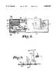
- FIG. 18is somewhat diagrammatic partial vertical sectional view illustrating constructional details of a preferred adapter for receiving a portable battery powered terminal, the terminal being shown as being inserted part way into the adapter channel, to the point of initial electrical contact; and also indicating in diagrammatic fashion a laser bar code scanner device in a separate vehicle mounting or holster means and coupled with the terminal via a wireless link.
- FIG. 1is an overall perspective representation of a dock or docking device 10 which represents an embodiment of the present invention.
- FIG. 1also shows a hand-held terminal 11, such as a data collection terminal 11, in a fully inserted position within the docking device 10. In such a fully inserted position, the data collection terminal 11 is positively retained by the docking device. The fully inserted position may sometimes be referred to herein as a locked position of the data collection terminal 11.
- a housing 12 of the data collection terminal 11is generally of elongate and rectangular shape. Such elongate shape of the data collection terminal 11 not only makes it easier for a person to hold the terminal 11 with one hand, but also provides lateral restraint as the data collection terminal 11 is inserted into the docking device 10.
- a retention cavity 13 of the docking device 10extends generally in a longitudinal direction generally centrally within the docking device 10.
- a cross section through the retention cavity 13is somewhat larger in area than a cross-sectional shape of the data collection terminal 11 and is, therefore, of ample size for receiving the data collection terminal 11 without undue restraint.
- FIG. 1shows the docking device 10 mounted onto a communications base 21, which, in turn is supported by a pivot mount 22.
- the communications base 21internally includes communication cable splitters and may provide, for example, a mounting surface 23 for communications and power plugs, such as connectors 24 and 25.
- a keyboard 26 and a display screen 27 of the data collection terminal 11desirably remain accessible while the data collection terminal 11 is retained in the docking device 10.
- An outer housing shell 30 of the docking device 10preferably has a C-shaped cross-sectional configuration, as shown in FIG. 4.
- the outer housing shell 30is the outer skeleton of the docking device 10 and imparts external ruggedness by preferably being constructed of an extruded aluminum channel, or other suitable structure.
- an open gap 31 between lateral caps 32 and 33 of the channel structure of the outer housing 30provides top access to keys 34 of the keyboard 26.
- FIG. 2shows a side view of the docking device 10.
- the channel member of the outer housing shell 30is more clearly shown as a modified channel in that sides 35, including the caps 32 and 33, have been partially cut back or removed adjacent the insertion end 16 of the docking device 10.
- the insertion end 16has the appearance of a stepped end.
- the outer housing shell 30is attached to the communications base 21.
- the communications base 21is, in turn, attached by typical threaded fasteners 36 to a mounting base 37 of the pivot mount 22.
- the docking device 10With a pedestal 38 being firmly attached to a mounting surface 39, the docking device 10 may be pivoted through a substantial arc as indicated by an arrow designated by the numeral 41 in FIG. 2, to selectively adjust the docking device 10 to any number of convenient orientations, an alternate horizontal orientation of the docking device 10, being shown in dashed lines designated by the numeral 42 in FIG. 2.
- the pivot mount 22may be rigidly locked in any of these adjusted positions by a hand knob 43.
- the use of the pivot mount 22is looked upon as particularly advantageous for mounting the docking device 10 onboard service vehicles, for example, such as fork lift trucks and the like.
- FIG. 3is a top or plan view of the docking device 10 showing, at least partially, several major structural elements of the docking device 10.
- the docking device 10is best suited for its intended purpose by exhibiting exceptional ruggedness for withstanding hazards and harsh treatment common to industrial environments, such as in factories and warehouses or on route delivery trucks.
- the docking device 10also provides protection for the data collection terminal 11 retained therein, and further provides minimal frictional resistance during insertion and retraction of the data collection terminal 11.
- the outer housing shell 30 in the form of an extruded aluminum channelhas been found to provide an acceptable degree of protection and ruggedness.
- a docking seat molding 46Inserted into the outer housing shell 30 are a docking seat molding 46, an insertion guide molding 47, and a seat base molding 48 as major internal structural elements, which may be constructed of molded high impact plastic, or other suitable material.
- the insertion guide molding 47is disposed at the insertion end 16 of the outer housing 30.
- the docking seat molding 46is disposed adjacent the insertion guide molding 47.
- the insertion guide molding 47 and the adjacent docking seat molding 46form, by their mutual longitudinally adjoining arrangement, a docking channel 49 for the data collection terminal 11, which merges into and terminates at its lower end in the retention cavity 13.
- the molded plastic elements of the docking seat molding 46, the insertion guide molding 47, and the seat base molding 48are further protected, aligned, and held in their respective positions by the outer housing shell 30.
- a preferred assembly sequencewould generally proceed by initially inserting of the docking seat molding 46 from the insertion end 16 into the channel of the outer housing shell 30.
- the docking seat molding 46which features right and left flanges 51 and 52 that establish the fully inserted position of the docking seat molding 46 within the outer housing shell 30, may then be appropriately fastened to a base wall 53 of the outer housing shell 30.
- the insertion guide molding 47may thereafter be slid into position at the insertion end 16 of the docking device 10 and fastened to the base wall 53 of the outer housing shell 30.
- the seat base molding 48may thereafter be slid into the outer housing shell 30 and into engagement with the docking seat molding 46 from the retention end 18 of the docking device 10, to be held in position, as herein will become more apparent, by a docking seat base plate 56.
- the top view of the docking device 10also depicts the presence, along right and left sides 57 and 58 of the docking device 10, right and left latch release levers 59 and 60, respectively.
- the docking device 11is generally symmetric about a central plane through a longitudinal axis or centerline designated by the numeral 61 as shown in FIG. 3.
- the right and left latch release levers 59 and 60are generally mirror images of each other and are preferably positioned such that one or the other is accessible by either a left-handed person or a right-handed person with equal ease.
- the data collection terminal 11, fully inserted in the docking device 10is retained by overlapping inner edges of the caps 32 and 33 of the outer housing shell 30.
- the caps 32 and 33constitute a substantially rigid and strong backing and support for underlying molded plastic retaining ledges 63 and 64 of the docking seat molding 46, the retaining ledges 63 and 64 forming upper, overhanging retention caps having inwardly facing surfaces that contact the data collection terminal 11 as the data collection terminal 11 is retained within the docking channel 49.
- the retention ledges 63 and 64are spaced so as not to impede access to the keyboard 34 of the data collection terminal 11 as the data collection terminal 11 is seated in the docking device 10.
- FIG. 4depicting an end view of the docking device 10 taken from the insertion end 16, shows a particularly advantageous structural feature of the docking device 10 and, particularly, of the docking seat molding 46 and the insertion guide molding 47.
- a clearly defined space 65is shown to exist between an inner base wall 66 of the docking channel 49 and an adjacent lower surface 67 of the data collection terminal 11, as inserted into the docking device 10.
- the data collection terminal 11has a handstrap 68, which may preferably form part of the data collection terminal 11 as a user enhancement and terminal protection device. A user may insert a hand between the data collection terminal 11 and the handstrap 68 to safely retain the data collection terminal 11, even though the user's handgrip on the data collection terminal 11 may be temporarily relaxed.
- the material of the handstrap 68may be an elastic woven, relatively soft material, or other suitable material.
- the presence of the handstrap 68may impede ready insertion or removal of the data collection terminal 11 from the docking device 10.
- upright walls 69 and 70 of the docking seat molding 46have sufficient height to fixedly establish a spacing between the retention ledges 63 and 64 and the inner base wall 66 of the docking channel 49.
- a pair of upper guide pins 71are laterally spaced transversely with respect to the centerline 61 through the docking channel 49.
- the pair of upper guide pins 71is mounted from below through the insertion guide molding 47 to extend from the inner base wall 66 toward the upper or open side of the outer housing shell 30, i.e., toward the gap 31.
- the upper guide pins 71are preferably spaced to engage rounded longitudinal edges of the housing 12 of the inserted data collection terminal 11.
- Extending guide ends 73 of the upper guide pins 71are sloped inwardly toward the centerline 61 through the docking channel 49 of the docking device 10.
- the extending guide ends 73are also convexly cylindrically rounded with respect to a cylindrical axis, which hypothetically extends in a plane transverse to the centerline 61 and parallel to the direction of the slope of the guide surfaces 73 toward the center of the docking channel 49, to crown the inwardly sloping guide ends 73 such that contact between the upper guide pins 71 and the housing 12 of the data collection terminal 11 becomes, at most, a line contact, if not a point contact, since rounded edges of the housing 12 are rounded substantially perpendicularly to the rounded guide ends 73 of the upper guide pins 71.
- the guide ends 73funnel the data collection terminal 11 toward the centerline 61 of the docking device 10.
- the docking seat molding 46has, laterally opposed near its center, a pair of lower guide pins 76.
- the lower guide pins 76are preferably disposed slightly closer to the centerline 61 and the centered data collection terminal 11. Extending guide ends 77 of the lower guide pins 76 are spherically crowned.
- the lower guide pins 76are, hence, not sloped toward the center as are the upper guide pins 71.
- the spherically crowned lower guide ends 77permit a smooth engagement along rounded lateral lower corners of the housing 12 of the data collection terminal 11.
- edge guide surfaces 78are disposed at the end of the docking channel 49 on both sides of the docking seat molding 46.
- the edge guide surfaces 78constitute part of the internal shape of the docking channel 49 and are part of the retention cavity 13 adjacent the retention end 18.
- the lateral edge guide surfaces 78position the data collection terminal 11 with respect to spring contacts 79.
- the spring contacts 79protrude through respective contact slots 80 at a docking seat 81 formed into the docking channel 49 by the docking seat molding is 46.
- the upper guide pins 71 and lower guide pins 76are preferably constructed of a low-friction plastic material, or other suitable material. By using the upper guide pins 71 and lower guide pins 76 in lieu of guiding surfaces, sliding friction forces between the data collection terminal 11 and the docking device 10 during the insertion or extraction of the data collection terminal 11 into or from the docking device 10 are advantageously minimized.
- Minimal insertion forcesare a distinct requirement for effortlessly inserting or removing the data collection terminal 11 from the docking device 10 as the relatively low insertion and extraction friction forces allow an operator or user of the data collection terminal 11 to one-handedly insert the data collection terminal 11 into, or to remove the data collection terminal 11 from, the docking device 10.
- One-handed insertion or removal of data collection terminals from dockshas been attempted prior to the present invention; however, sliding friction between the data collection terminals and those docks has heretofore required an increased effort on the part of an operator.
- substantially effortless, one-handed insertion or removal of the data collection terminal 11 into or out of the docking device 10tends to reduce the risk of an operator dropping the data collection terminal 11.
- substantially effortless insertion or removalmay permit an operator to direct an increased amount of his or her attention to other concurrent concerns.
- the guiding function of the extending guide ends 73 and 77 of the respective upper and lower guide pins 71 and 76has been found to be smooth but precise, readily centering the data collection terminal 11 within the retention cavity 13.
- the housing 12 of the data collection terminal 11may actually be lifted slightly from the guide ends 77 of the lower guide pins 76.
- the spring contacts 79are mounted on a contact support bracket 84 of a spring contact assembly 85, with electrical conductor leads 86 leading to the communications base 21.
- the electrical conductor leads 86may be part of a flexible printed circuit cable assembly, or they may consist of individual electrical leads or bonded ribbon conductors, generally referred to as a cable assembly 86.
- the contact support bracket 84shows preferred mounting holes 87 for mounting the contact support bracket 84 to the underside of the docking seat molding 46 prior to its assembly as described.
- the spring contacts 79extend through the contact slots 80 into the path of the data collection terminal 11, such that a data collection terminal 11 being inserted into the docking device 10 will engage and deflect the spring contacts 79 toward the contact slots 80, thereby resiliently tensioning the spring contacts 79 to exert a contact force against complementary surface contacts 88, as shown in FIG. 7.
- the described structuresubstantially minimizes, if not entirely eliminates, tendency of the spring contacts 79 to bounce and thereby inadvertently electrically decouple from the complementary surface contacts 88 as the data collection terminal 11 is retained and latched within the retention cavity 13 of the docking device 10.
- a retention pawl assembly 89 of a retention pawl mechanism 90that further includes a preferred leaf spring structure 91, preferably attached to the retention end 18 of the outer housing shell 30, such as by threaded screws, riveting, or the like.
- the retention pawl assembly 89includes at least one, and preferably two, retention pawl levers 93 which are assembled adjacent one another on a square pivot shaft 94, symmetrically with respect to the centerline 61. Pivot ends 95 of the retention pawl levers 93 have square mounting apertures 96 that restrict rotational movement of the retention pawl levers 93 with respect to the pivot shaft 94.
- Typical retainer clip rings 97retain and support the retention pawl levers 93 from moving outwardly away from the center of the pivot shaft 94, while a compressed compression spring 98 urges the retention pawl levers 93 against the respective retainer clip rings 97.
- Outer ends 101 opposite the pivot or mounting ends of the retention pawl levers 93carry upwardly pointed hooks or prongs 102, that are intended to engage and retain the data collection terminal 11 as the outer ends 101 are moved upwardly into engagement with the data collection terminal 11.
- the outer ends 101 carrying the prongs 102protrude through the docking seat molding 46 via two respective pawl openings 103.
- the pawl openings 103 and the respective protrusion of the prongs 102are closer to the insertion end 16 of the docking device 10 than to the spring contact slots 80.
- Bearing ends 104 and 105 of the respective left and right latch release levers 59 and 60have internal square openings 107 to slidingly engage the square pivot shaft 94 without rotational freedom, and have rotational bearing surfaces 109 that, upon assembly, become seated in complementary bearing apertures 110 of the docking seat molding 46.
- Two additional retainer clip rings 97prevent the latch release levers, 59 and 60, from moving inward on the pivot shaft 94 such that the latch release levers, 59 and 60, remain in pivot bearing contact with the docking seat molding 46 and to permit the retention pawl assembly 89 to pivot in its entirety with respect to the docking seat molding 46.
- two complementary leaf springs 114 of the leaf spring structure 91engage the respective retention pawl levers 93 and resiliently urge the prongs 102 upwardly through the docking seat molding 46 into the path of the data collection terminal 11 being inserted into the docking device 10.
- the leaf springs 114have a desirable spring constant and a pretension, when fully extended, to urge the prongs 102 into a retaining recess of the data collection terminal 11 but, also, to urge the data collection terminal 11 in a direction toward and against the retaining ledges 63 and 64 of the docking seat molding 46 such that any clearances between the insertion space of the retention cavity 13 and the data collection terminal 11 is taken up toward the retaining ledges 63 and 64 and in a direction away from the spring contacts 79.
- the normal extent of the spring contacts 79 into the docking channel 49is such that, in an uppermost position of the data collection terminal 11, the spring contacts 79 remain in forced contact with the complementary surface contacts 88.
- the contact force between the spring contacts 79 and the complementary surface contacts 88 of the data collection terminal 11will be an optimally minimum, forced contact between the respective sets of the spring contacts 79 and the surface contacts 88. Any vibration or shock which may cause movement of the data collection terminal 11 will tend to increase the contact force between the respective spring contacts 79 and surface contacts 88.
- the seat base molding 48is inserted from the retention end 18 into the outer housing shell 30.
- Two coil springs 116are fitted into spring-retaining guide columns 117 of the seat base molding 48.
- the guide columns 117slidingly fit into complementary guide recesses 118 of the docking seat molding 46.
- the coil springs 116become compressed and the seat base molding 48 is urged in a direction toward the insertion end 16 until restrained by molded ledges 119 of the docking seat molding 46.
- the spring constant of the coil springs 116, their lengths, and the total compression force involved, when assembled as described herein,is desirably chosen to be in excess of the total weight of the data collection terminal 11 inserted into the docking device 10.
- FIG. 6, depicting a side view of the data collection terminal 11,shows a surface contact assembly 121 adjacent a lower end 120 thereof.
- the surface contact assembly 121has several functions. Firstly, the surface contacts 88 of the data collection terminal 11 are molded into the surface contact assembly 121. Secondly, the surface contact assembly 121, when mounted to the lower end 120 of the data collection terminal 11, retains one end of the handstrap 68 that stretchedly extends longitudinally along the underside of the data collection terminal 11. The surface contact assembly 121 also extends away from the sloped underside of the lower end of the data collection terminal 11.
- An upper ledge 123forms retaining ledges or seats 124 which are positioned to become engaged by the prongs 102, as shown in FIG. 5, to positively retain the data collection terminal 11, when inserted into the retaining cavity 13 of the docking device 10.
- the upper ledge 123forms, with the sloping housing 12, the retaining seats 124 that become engaged by the prongs 102 at substantially right angles to the longitudinal insertion direction of the data collection terminal 11 within the retention cavity 13.
- the spring bias of the prongs 102urge the data collection terminal 11 toward the retaining ledges 63 and 64, the data collection terminal 11 becomes latched into position with a positive lock.
- Any resiliency in the pawl levers 93is substantially perpendicular to a removal force, and any movement of the data collection terminal 11 away from the upper retaining ledges 63 and 64 only increases the force with which the retention pawl levers 93 engage the seats in the upper ledge 123.
- FIG. 7shows a clearly defined width, "W", of the surface contact assembly 121.
- the surface contact assembly 121also extends away from the housing 12 across its width "W”, projecting at the lower end 120 of the data collection terminal 11 away from the generally smooth contour of the housing 12.
- Outer surfaces across the width of the surface contact assembly 121are ideally chosen as reference edges.
- the reference edgesestablish a precise transverse position of the surface contacts 88 with respect to the docking device 10 as the surface contact assembly 121 is guided along the complementarily spaced edge guide surfaces 78 of the docking seat molding 46.
- the final alignmentprior to latching, centrally aligns the data collection terminal 11 with respect to the docking device 10.
- the surface contacts 88are always precisely aligned with the complementary spring contacts 79.
- the opposing edge guide surfaces 78 of the docking seat molding 46are spaced to slidingly accept the surface contact assembly 121 with a minimum of acceptable clearance beyond the width, "W", of the assembly 121.
- the guide ends 77 of the lower guide pins 76preferably have generally spherically shaped surfaces with uniform rounding thereabout so as not to interfere with lateral repositioning of the data collection terminal 11 during final alignment of the respective surface contacts 88 with respect to the spring contacts 79 in the docking seat molding 46.
- FIG. 8is a fragmentary, side elevational view of the docking device 10, and particularly of the retention end 18 of the docking device 10.
- the retention pawl mechanism 90including the leaf springs 114 and the latch release levers 59 and 60, are shown in a primary engaged position with the data collection terminal 11 being in a fully inserted position. In this fully inserted position, the coil springs 116 are compressed and the seat base molding 48 exerts an urging force against the lower end 120 of the data collection terminal 11.
- the latch release levers 59 and 60are both directly coupled through the pivot shaft 94 to the retention pawl levers 93.
- the retention pawl levers 93pivot in unison with the pivot shaft 94, and the prongs 102 are moved to an alternate, disengaged position, as shown by the phantom lines for illustrative purposes only.
- the data collection terminal 11is released from the latched or positively locked retention position.
- the seat base molding 48urges the data collection terminal 11 toward the insertion end 16 of the docking device 10. Allowing the latch release lever, either 59 or 60, to return to its normal position after a mere momentary depression no longer accomplishes a return of the prongs 102 to their prior position against the retention seats 124 in the upper ledge 123 of the surface contact assembly 121.
- the data collection terminal 11has then already moved from its fully inserted position to a different position, such as resting against the seat base molding 48, for example, as shown in FIG. 15.
- the seat base molding 48has been urged by the coil springs 116 against the molded ledges 119.
- the retention pawl mechanism 90accomplishes, as described, an automatic latching of the data collection terminal 11 into the docking device 10 as the data collection terminal 11 is fully inserted against the spring bias exerted by the seat base molding 48. It should be apparent that the docking arrangement provided by the present invention is readily accomplished by an operator with a single-handed movement, no other manual locking operation being necessary. When it is desired to remove the data collection terminal 11 from the docking device 10, a single-handed operation is, again, all that is required to release the data collection terminal 11. By depressing either of the latch release levers 59 or 60, the data collection terminal 11 is released, but remains loosely retained in the docking channel 49 to be removed by an operator at will. The retention pawl mechanism 90 accomplishes thereby a desired single-handed latch and release function of the docking device 10, including a selectively implemented non-latched, temporary holding function for a data collection terminal 11.
- FIG. 9shows an exploded view of parts of the retention pawl assembly 89.
- the retainer clip rings 97are insertible into grooves 126 that retain the retention pawl levers 93 on the square pivot shaft 94 with the compression spring 98 disposed there between.
- FIG. 10shows the assembled retention pawl mechanism 90 in the end view of the retention end 18 of the docking device 10.
- the latch release levers 59 and 60are assembled onto the pivot shaft 94 and are, with their circular bearing surfaces 109, disposed within the corresponding molded bearing apertures 110 of the docking seat molding 46.
- the seat base molding 48is guided by the docking seat molding 46 and is retained within the outer housing shell 30, particularly by the caps 32 and 33 thereof.
- FIG. 11a placement of the retainer clip ring 97 on the pivot shaft 94 and against the retention pawl lever 93 is depicted, showing a circularly machined neck of the groove 126 in the pivot shaft 94.
- FIG. 12is an enlarged cross-sectional side view illustrating a mounting of the spring contact assembly 85 to an underside of the docking seat molding 46.
- the spring contacts 79extend through respective contact slots 80 through the docking seat molding 46 and into contact with the respective surface contacts 88 on the surface contact assembly 121. Because of the urging force of the prong 102 against the lower end 120 of the data collection terminal 11, a gap 130 may exist between the guide ends 77 of the lower guide pins 76 and an underside 131 of the data collection terminal 11. Thus, when fully inserted and in a latched position within the docking device 10, the data collection terminal 11 would typically be biased, at least at the retention end 18 of the docking device 10, against the retaining ledges 63 and 64.
- the spring contacts 79exert a minimum, yet optimum, contact force against the respective, mating surface contacts 88 of the data collection terminal 11. Any vibration of the data collection terminal 11 within the retention cavity 13 with vibratory movement toward the lower guide pins 76 tends to increase the contact force between the spring contacts 79 and the surface contacts 88.
- the mass of the spring contacts 79is much less than the mass of the data collection terminal 11 such that, in a vibratory environment of the docking device 10, the spring contacts 79 tend to track any vibratory movement of the data collection terminal 11 between the retaining ledges, 63 and 64, and the lower guide pins 76, thereby virtually eliminating any risk of contact bounce between the spring contacts 79 and the surface contacts 88 of the data collection terminal 1. Any risk of contact bounce between the respective spring contacts 79 and surface contacts 88 would be highly detrimental to a contemplated function of the docking device 10 for transferring data between the data collection terminal 11 and other data devices (not shown but represented by the docking device 10) which may be coupled directly or indirectly to the docking device 10.
- batteries of the data collection terminal 11may be recharged and, simultaneously therewith, data may be up-loaded or down-loaded between another data device, represented by the docking device 10, and the data collection terminal 11.
- An outer end 132 of the spring contacts 79normally rests against the underside of the docking seat molding 46, the outer end 132 serving as a restraint to excessive movement of the spring contacts 79 into the retention cavity 13.
- the outer ends 132therefore allow the spring contacts 79 to have an initial spring bias force designed into the spring contacts 79 in order to maintain a minimum contact force between the spring contacts 79 and the surface contacts 88.
- An angular orientation of the surface contacts 88 with respect to the longitudinal extent of the data collection terminal 11tends to cam the spring contacts 79 slopingly against the surface contacts 88 as the data collection terminal 11 is inserted and latched into the docking device 10.
- the sloped orientation of the surface contacts 88 and the resulting camming action during the insertion of the data collection terminal 11advantageously provide for contact wiping action during each insertion operation of the data collection terminal 11.
- the sloped orientation of the surface contacts 88may also provide limited contact wiping action during vibrational movement of the data collection terminal 11 within the docking device 10.
- FIG. 13An enlarged view of the spring contact assembly 85 is shown in FIG. 13.
- the spring contacts of the spring contact assembly 85are preferably molded into, but may otherwise be attached to, the contact support bracket 84.
- a third mounting orifice 133which is offset from the mounting holes 87, provides torsional stability to resist the spring force exerted on the contact support bracket 84 when the spring contacts 79 engage the surface contacts 88 of the data collection terminal 11.
- FIG. 14shows particular details of the preferred guiding arrangement for the data collection terminal 11 at the retention end 18 of the docking device 10.
- the lower guide pins 76provide sliding support for the data collection terminal 11, while opposing edge guide surfaces 78 guide the data collection terminal 11, see FIG. 3, into contact with the spring contacts 79.
- FIG. 15shows a plan view of the data collection terminal 11 being removed in a direction toward the insertion end 16 of the docking device 10, as indicated by an arrow designated by the numeral 136.
- FIG. 15also shows a mechanical advantage in the latch release levers 59 and 60 with respect to the force application by the prongs 102 against the data collection terminal 11, as the data collection terminal 11 is fully inserted into the docking device 10.
- "D1"designates a first distance from an axis 137 of the pivot shaft 94 to the prongs 102
- “D2"designates a second distance, from the pivot axis 137 to where an operator would have access to the latch release levers 59 and 60, that is desirably significantly longer than "D1".
- a depression force on either of the latch release levers, 59 or 60, to release the retention pawl levers 93 from engagement with the data collection terminal 11,is a corresponding fraction of the force by which the prongs 102 force an inserted data collection terminal 11 upwardly against the retaining ledges 63 and 64 beneath the caps 32 and 33.
- the latch release levers 59 and 60are preferably formed of a light molded plastic structure in order to minimize weight and mass of the latch release levers 59 and 60. Strength of the latch release levers 59 and 60 is enhanced by providing an angular structure therefor. Accordingly, the release levers 59 and 60 are both formed or molded of respective horizontally and vertically disposed strip-like walls or beams, that are respectively designated by the numerals 138 and 139, as shown in FIG. 14. The beams 138 and 139 are merged along a common comer into a unitary structure having angular cross section.
- the angular structure of the latch release lever 60is preferably a mirror image of that of the release lever 59, also having horizontal and vertical beams 138 and 139 that merge along one edge into a structure having angular cross section, as shown in the drawings.
- Other ways of minimizing the weight versus strength of the release leversmay be implemented in view of the teaching herein of the need to minimize the mass of the latch release levers 59 and 60. A mass or weight minimization is also desirable to avoid accidental release of the data collection terminal 11 under severe shock conditions.
- the docking device 10optionally includes a bracket 141 for receiving a scanner 143, such as a laser scanner, operably connected to the data collection terminal 11, such as by a spirally wound cord 145. As the lower end 120 of the data collection terminal 11 will be inserted into the docking device 10, the cord 145 in connected through a connector 147 to the data collection terminal 11.
- a scanner 143such as a laser scanner
- the bracket 141has an outer retaining wall 149 that is spaced from a side wall 151 at a distance that is less than the width of a handle 153 of the scanner 143, and a lower retaining wall 155 that spaces the scanner 143 generally alongside the data collection terminal 11 as it is contained within the docking device 10.
- the outer retaining wall 149has a flare 157 to facilitate insertion of the scanner 143 into the bracket 141.
- the outer retaining wall 151 and the lower retaining wall 155are constructed of resilient material such that the scanner 143 is reliably clamped into the bracket 141 as the scanner 143 is inserted thereinto, but not so tightly but what the scanner 143 can be readily, swiftly and one-handedly removed by a user.
- the bracket 141may also include cushioning means 157 to dampen vibrations developed in a more abusive environment, as hereinbefore described.
- the scanner 143can be removed for operable use as the data collection terminal 11 remains in the docking device 10, in which event controls of the data collection terminal 11 are accessible to the user for interactive input while using the scanner 143, if necessary.
- a terminal 2 10is shown in initial contact with an adapter indicated at 220.
- the adaptermay have a contact assembly 225 including spring fingers 226 aligned with respective terminal contacts 227.
- adapter 220is shown as comprising a base part 231 which has a pair of upstanding generally C shaped parts such as 234 which define a channel for receiving the terminal 210.
- the parts 233may have sloping surfaces such as 236 which limit the downward movement of a terminal into the receiving channel, and serve to frictionally retain the terminal with a suitable degree of pressure between contacts such as 227 and mating spring fingers such as 226.
- connectionsuch as 226, 227, FIG. 18, may be maintained by a frictional ball and socket type detent such as indicated at 280 which seats with an audible click into a terminal recess 281 when correct deflection of spring contacts 226 has been achieved.
- FIG. 18shows a holster 290 on base 231 for receiving and securely retaining a scanner such as 285, e.g. by a resilient liner 291 of the holster 290 frictionally engaging with a barrel 292 of the scanner.
- the holster 290may be constructed e.g. at 293 to hold the handgrip part 294 and trigger 295 clear thereof so that the scanner is quickly and easily removed by manually grasping the handgrip part 294, and so that the trigger 295 will not be actuated as the scanner is manually inserted into the holster 290.
- the scanner for bar codesneed not be physically attached to the terminal.
- a lot of the software effort involvedmay represent the accommodation of the periodic removal of major sections of the system to do remote scanning of marginally accessible codes.
- the scanneris always attached to the terminal by a pendant cable and if the code to be scanned is beyond the reach of the cable then the terminal must necessarily be removed from its holster.
- the terminalmay represent a very significant portion of a "LAN" system and to remove it in this fashion may disable the system generally. Placing the terminal in its holster again may entail the reestablishment of the hierarchial or virtual address structure that was established prior to the removal of the terminal.
- the terminalsnow incorporate various types of scanner interfaces. Some of them have been add-on devices to accommodate scanner types manufactured by third parties. Others have been built-in and have been used to communicate with scanners such as shown in U.S. Pat. No. 4,766,300 issued Aug. 23, 1988 to Chadima. Some of these handheld terminal devices provide power converters accommodating the requirements idiosyncratic to specific scanner types. All of such scanners directly draw power from the terminal, reducing operational time per battery charge.
- a scanner such as 285, FIG. 18,may be operated while disconnected from the terminal on a permanent basis. Terminals presently connect with a host by an RF link and maintain contact without benefit of cable. Of course, terminals mounted on a vehicle will be drawing their power from the vehicular electrical system. The power requirements for a scanner connected by a cable to a terminal on a vehicle will not be a large factor in the power budget imposed upon the terminal.
- Detaching the terminal from the scanner 285 completelyprovides benefits in the area of flexibility and ease of use. Since the scanner 285 doesn't require contact with or attachment to the terminal the job of providing operating power no longer is the province of the terminal. The scanner, being completely portable would require its own battery pack but this pack would not have to be unusually capacious. Once the scanning function has been performed the scanner can be reinserted in its holster 290 on the vehicle and charged back up to full capacity from the vehicle power by its own charger indicated at 297.
- the communication link replacing the cablemay be ultrasonic but could also be infrared or even another very low power RF link as diagrammatically indicated at 300.
- Various modulation and demodulation schemescould be employed and the choice of the most appropriate means of encoding data on the channel would depend greatly upon the channel type used.
- the terminalswould still incorporate a form of scanner interface but the link would not be mechanical. It would be desirable to provide a bidirectional data path.
- the scannerwould include the matching interface to implement the link and using a bidirectional data path the scanner could receive an acknowledgment after a scan. Reception of such an acknowledgment would constitute an indication of a valid scan and the illumination of an indicator light would provide operator feedback. The lack of a response from the terminal in a specified time period would constitute a negative acknowledgment and another indication on the scanner would signal the operator that another scan was necessary.
- Appropriate scanners for this type of operationwould include current wand and modified CCD type scanners of Norand Corporation and a number of other manufacturer's laser scanners.
- This scannerwould be used typically, by a forklift operator in close proximity to his vehicle. Limited range would not be a significant deterrent here and may even be a benefit in an operation where multiple units are in use.
Landscapes
- Engineering & Computer Science (AREA)
- Physics & Mathematics (AREA)
- Electromagnetism (AREA)
- Theoretical Computer Science (AREA)
- General Physics & Mathematics (AREA)
- Toxicology (AREA)
- Artificial Intelligence (AREA)
- Computer Vision & Pattern Recognition (AREA)
- General Health & Medical Sciences (AREA)
- Health & Medical Sciences (AREA)
- Signal Processing (AREA)
- General Engineering & Computer Science (AREA)
- Computer Networks & Wireless Communication (AREA)
- Quality & Reliability (AREA)
- Computer Hardware Design (AREA)
- Human Computer Interaction (AREA)
- Mechanical Engineering (AREA)
- Automation & Control Theory (AREA)
- Casings For Electric Apparatus (AREA)
Abstract
Description
______________________________________U.S. AttorneyApplication No. Filing Date Inventor(s) Docket No.______________________________________07/305,302 January 31, 1989 G. Hanson, et al. 6649The subject matter of Application No. 07/305,302 has been published inU.S. Pat. No. 5,289,378 issued February 22, 1994 based on a continuationof Application No. 07/305,302.)07/345,200 April 28, 1989 G. Hanson 6649X07/347,602 May 3, 1989 G. Hanson, et al. 6649XXThe subject matter of Application No. 07/347,602 has been published inU.S. Pat. No. 5,331,580 issued July 19, 1994 based on a continuationof Application No. 07/347,602.)07/357,849 May 3, 1989 G. Hanson, et al. 6504XXThe subject matter of Application No. 07/347,849 has been published inU.S. Pat. No. 5,195,183 issued March 16, 1993 based on a continuationof Application No. 07/347,849.)______________________________________
Claims (20)
Priority Applications (1)
| Application Number | Priority Date | Filing Date | Title |
|---|---|---|---|
| US08/772,538US5888087A (en) | 1989-01-31 | 1996-12-24 | One-handed dock for a portable data collection terminal |
Applications Claiming Priority (10)
| Application Number | Priority Date | Filing Date | Title |
|---|---|---|---|
| US30530289A | 1989-01-31 | 1989-01-31 | |
| US34520089A | 1989-04-28 | 1989-04-28 | |
| US56199490A | 1990-07-31 | 1990-07-31 | |
| US90913992A | 1992-07-06 | 1992-07-06 | |
| US5070493A | 1993-04-21 | 1993-04-21 | |
| US08/146,882US5466170A (en) | 1993-11-02 | 1993-11-02 | End-insertion data terminal dock with positive data terminal lock and bounce-preventing contact engagement bias |
| US08/171,390US5517434A (en) | 1989-01-31 | 1993-12-21 | Data capture system with communicating and recharging docking apparatus and hand-held data terminal means cooperable therewith |
| US55776295A | 1995-11-13 | 1995-11-13 | |
| US08/647,477US6375344B1 (en) | 1989-01-31 | 1996-05-14 | Data capture system with communicating and recharging docking apparatus and hand-held data terminal means cooperable therewith |
| US08/772,538US5888087A (en) | 1989-01-31 | 1996-12-24 | One-handed dock for a portable data collection terminal |
Related Parent Applications (2)
| Application Number | Title | Priority Date | Filing Date |
|---|---|---|---|
| US55776295AContinuation-In-Part | 1989-01-31 | 1995-11-13 | |
| US08/647,477Continuation-In-PartUS6375344B1 (en) | 1989-01-31 | 1996-05-14 | Data capture system with communicating and recharging docking apparatus and hand-held data terminal means cooperable therewith |
Publications (1)
| Publication Number | Publication Date |
|---|---|
| US5888087Atrue US5888087A (en) | 1999-03-30 |
Family
ID=27578211
Family Applications (1)
| Application Number | Title | Priority Date | Filing Date |
|---|---|---|---|
| US08/772,538Expired - Fee RelatedUS5888087A (en) | 1989-01-31 | 1996-12-24 | One-handed dock for a portable data collection terminal |
Country Status (1)
| Country | Link |
|---|---|
| US (1) | US5888087A (en) |
Cited By (51)
| Publication number | Priority date | Publication date | Assignee | Title |
|---|---|---|---|---|
| US6042414A (en)* | 1997-11-14 | 2000-03-28 | Intermec Ip Corp. | Vehicle dock for portable data collection terminal |
| WO2000066003A1 (en)* | 1999-05-04 | 2000-11-09 | Sonosite, Inc. | Mobile ultrasound diagnostic instrument and docking stand |
| US6193546B1 (en)* | 1999-03-16 | 2001-02-27 | Ericsson Inc. | Support assembly for personal electronic device and method for using the same |
| US6299467B1 (en)* | 2000-04-18 | 2001-10-09 | Advanced Connecteck Inc. | Electrical connector |
| US6364697B1 (en)* | 2000-05-12 | 2002-04-02 | Palm, Inc. | Palmtop computer docking system |
| US6364839B1 (en)* | 1999-05-04 | 2002-04-02 | Sonosite, Inc. | Ultrasound diagnostic instrument having software in detachable scanhead |
| US6386884B1 (en) | 2000-05-12 | 2002-05-14 | Northstar Systems, Inc. | Rotatable connector system |
| USD475011S1 (en) | 2002-08-26 | 2003-05-27 | Sony Corporation | Battery charger |
| US20030132292A1 (en)* | 2002-01-11 | 2003-07-17 | Hand Held Products, Inc. | Transaction terminal including imaging module |
| US6621942B1 (en)* | 1989-09-29 | 2003-09-16 | Intermec Ip Corp. | Data capture apparatus with handwritten data receiving component |
| US6633482B2 (en)* | 2000-05-01 | 2003-10-14 | Siemens Vdo Automotive Corporation | System for adapting driver information systems to existing vehicles |
| US20030229793A1 (en)* | 2002-01-11 | 2003-12-11 | Mccall Melvin D. | Transaction terminal comprising imaging module |
| US6716058B2 (en)* | 2001-08-21 | 2004-04-06 | Samsung Electronics Co., Ltd. | Cradle device of portable terminal |
| US20040150963A1 (en)* | 2003-01-31 | 2004-08-05 | Sonosite, Inc. | System for use with a modular apparatus for diagnostic ultrasound |
| US20040152982A1 (en)* | 2002-03-29 | 2004-08-05 | Sonosite, Inc. | Modular apparatus for diagnostic ultrasound |
| US20040210759A1 (en)* | 2002-01-11 | 2004-10-21 | Fitch Timothy R. | Transaction terminal |
| US20050039052A1 (en)* | 2002-01-11 | 2005-02-17 | O'donnell James | Ease of use transaction terminal |
| US20060024107A1 (en)* | 2004-07-29 | 2006-02-02 | Zih Corp. | Docking station and associated method for docking a portable printer |
| US20060028528A1 (en)* | 2004-07-29 | 2006-02-09 | Zih Corp. | Interchangeable module for a portable printer and system for operating the same |
| US20060289654A1 (en)* | 2005-06-27 | 2006-12-28 | Robinson Michael D | Method and system for linking a wireless hand held optical reader with a base unit or other wireless device |
| US20070040084A1 (en)* | 2005-06-03 | 2007-02-22 | Lane Sturman | Support arm assembly |
| US20070201202A1 (en)* | 2006-02-09 | 2007-08-30 | Tempus Computers Limited | Docking station |
| US20070284441A1 (en)* | 2006-06-13 | 2007-12-13 | Joseph Walczyk | Method and apparatus for uniquely associating a bar code reading terminal to a cash register in a retail store network |
| US20080227336A1 (en)* | 2007-03-12 | 2008-09-18 | Michael Kleber | Contacting appliance and contacting arrangement for mobile electrical devices |
| US20080234011A1 (en)* | 2003-10-31 | 2008-09-25 | Fujitsu Limited | Charging communication-adaptor for mobile device |
| US7479946B2 (en)* | 2002-01-11 | 2009-01-20 | Hand Held Products, Inc. | Ergonomically designed multifunctional transaction terminal |
| US7483417B2 (en) | 1996-04-18 | 2009-01-27 | Verizon Services Corp. | Telephony communication via varied redundant networks |
| US7664097B2 (en) | 1996-04-18 | 2010-02-16 | Verizon Services Corp. | Telephone service via networking |
| US7813332B1 (en) | 1997-03-19 | 2010-10-12 | Verizon Services Corp. | Voice call alternative routing through PSTN and internet networks |
| US7817619B1 (en) | 1996-12-18 | 2010-10-19 | Verizon Services Corp. | Internet long distance telephone service |
| US7830860B2 (en) | 1997-03-11 | 2010-11-09 | Verizon Services Corp. | Packet data network voice call quality monitoring |
| US7849250B2 (en) | 2006-10-31 | 2010-12-07 | Sonosite, Inc. | Docking station with hierarchal battery management for use with portable medical equipment |
| US20110075340A1 (en)* | 2008-06-18 | 2011-03-31 | Biao Qin | Portable Electronic Computer |
| US7948968B2 (en) | 1997-09-16 | 2011-05-24 | Verizon Communications Inc. | Network session management |
| US7959080B2 (en) | 2008-03-11 | 2011-06-14 | Xpress Systems, Llc | System for printing hospital labels and wristbands |
| US20120329334A1 (en)* | 2011-06-17 | 2012-12-27 | Molex Incorporated | Connector |
| US8398408B1 (en) | 2009-02-25 | 2013-03-19 | Sonosite, Inc. | Charging station for cordless ultrasound cart |
| US8938062B2 (en) | 1995-12-11 | 2015-01-20 | Comcast Ip Holdings I, Llc | Method for accessing service resource items that are for use in a telecommunications system |
| US9191505B2 (en) | 2009-05-28 | 2015-11-17 | Comcast Cable Communications, Llc | Stateful home phone service |
| US9935668B1 (en) | 2017-02-16 | 2018-04-03 | Datron World Communications, Inc. | Detachment mechanism and indicator for mobile mount portable radio and method for the same |
| EP3430940A1 (en)* | 2017-07-17 | 2019-01-23 | Hand Held Products, Inc. | Device retaining mechanism |
| US20210182514A1 (en)* | 2019-12-13 | 2021-06-17 | Zebra Technologies Corporation | Industrial digital barcode reader |
| US11068680B1 (en) | 2020-04-17 | 2021-07-20 | Cognex Corporation | Latch and hinge systems for base stations and handheld devices |
| US11076032B1 (en)* | 2020-05-26 | 2021-07-27 | National Products, Inc. | Cradles for mobile devices with a plunger lock and methods of making and using |
| US11277506B2 (en) | 2020-05-26 | 2022-03-15 | National Products, Inc. | Cradles for mobile devices with one or more biasing tabs and methods of making and using |
| US11416696B2 (en) | 2020-04-17 | 2022-08-16 | Cognex Corporation | Latch and hinge systems for base stations and handheld devices |
| US20220352682A1 (en)* | 2021-04-30 | 2022-11-03 | National Products, Inc. | Dock with flexible locator pins and methods of making and using |
| US12126199B2 (en) | 2021-08-09 | 2024-10-22 | National Products, Inc. | Cradles for a mobile device including a cavity for a wireless device and methods of making and using |
| US12158776B2 (en) | 2022-04-25 | 2024-12-03 | National Products, Inc. | Docks for mobile devices with simultaneous data transfer and charging and systems and methods using the docks |
| US12298809B2 (en) | 2023-07-05 | 2025-05-13 | National Products, Inc. | Heating module for electronic device dock and methods of making and using |
| US12341550B2 (en) | 2014-02-24 | 2025-06-24 | National Products, Inc. | Docking sleeve with electrical adapter |
Citations (88)
| Publication number | Priority date | Publication date | Assignee | Title |
|---|---|---|---|---|
| CH173434A (en)* | 1934-04-06 | 1934-11-30 | Ruf Buchhaltung A G | Typewriter case. |
| US2024622A (en)* | 1934-04-25 | 1935-12-17 | Bates Lab Inc | Writing machine |
| US2794664A (en)* | 1955-03-31 | 1957-06-04 | A L Smith Iron Company | Latches |
| US3143697A (en)* | 1962-05-31 | 1964-08-04 | Gen Electric | Toothbrush storage case and battery charger |
| US3348116A (en)* | 1964-10-02 | 1967-10-17 | Gen Electric | Electric knife storage case and battery charger |
| US3390319A (en)* | 1965-10-21 | 1968-06-25 | Dominion Electric Corp | Charging unit for a battery-containing handle for an electric knife or the like |
| US3745565A (en)* | 1971-04-29 | 1973-07-10 | Thorn Electrical Ind Ltd | Panel structure for mounting electrical components to provide front access thereto |
| US3826900A (en)* | 1972-10-13 | 1974-07-30 | Ncr | Cordless scanning probe |
| US3830554A (en)* | 1973-05-31 | 1974-08-20 | Singer Co | Locking device for sewing machine cabinet support platforms |
| US3895768A (en)* | 1974-02-08 | 1975-07-22 | Harold G Scheck | Security clamp |
| US4038535A (en)* | 1976-01-05 | 1977-07-26 | Texas Instruments Incorporated | Calculator-print cradle system |
| US4084214A (en)* | 1976-05-13 | 1978-04-11 | Ebco Industries, Ltd. | Modular housing for electronic apparatus |
| US4141616A (en)* | 1977-11-11 | 1979-02-27 | Motorola, Inc. | Unitized connector arrangement for electrical apparatus |
| US4208081A (en)* | 1979-01-03 | 1980-06-17 | International Business Machines Corporation | Easily reconfigurable data entry terminal |
| GB2045726A (en)* | 1979-04-03 | 1980-11-05 | Tohpre Ind Co Ltd | A recording paper holder for use with an appliance such as an electronic calculator |
| JPS5634468A (en)* | 1979-08-31 | 1981-04-06 | Seiko Epson Corp | Machine with printer |
| US4345147A (en)* | 1980-11-14 | 1982-08-17 | International Telephone And Telegraph Corporation | Vehicle mounted mobile business data handling system |
| US4387297A (en)* | 1980-02-29 | 1983-06-07 | Symbol Technologies, Inc. | Portable laser scanning system and scanning methods |
| US4396985A (en)* | 1980-01-16 | 1983-08-02 | Omron Tateisi Electronics Co. | Electronic cash register system for food dispensing business |
| US4397513A (en)* | 1981-04-08 | 1983-08-09 | Amp Incorporated | Cartridge holder and connector system |
| US4403271A (en)* | 1980-07-28 | 1983-09-06 | International Business Machines Corporation | Apparatus for mounting and packaging data processing devices |
| US4409470A (en)* | 1982-01-25 | 1983-10-11 | Symbol Technologies, Inc. | Narrow-bodied, single-and twin-windowed portable laser scanning head for reading bar code symbols |
| US4458813A (en)* | 1982-01-21 | 1984-07-10 | Superscope, Inc. | Housing for a video cassette playback machine |
| US4468750A (en)* | 1978-10-10 | 1984-08-28 | International Business Machines Corporation | Clustered terminals with writable microcode memories & removable media for applications code & transactions data |
| US4481458A (en)* | 1983-04-11 | 1984-11-06 | Levitt-Safety Limited | Miners lamp power pack |
| DE8438263U1 (en)* | 1984-12-29 | 1985-03-28 | Kleinmann, Harald, 6500 Mainz | Housing for holding a computer and its components |
| DE8500180U1 (en)* | 1985-01-05 | 1985-05-09 | Hindermann, Manfred, 4795 Delbrück | Box or suitcase for computers |
| US4527285A (en)* | 1982-03-29 | 1985-07-02 | International Business Machines Corporation | Pluggable terminal architecture |
| GB2153237A (en)* | 1984-02-02 | 1985-08-21 | Hendry Robert Leishman | Modular diving control system |
| DE3408594A1 (en)* | 1984-03-09 | 1985-09-12 | Weidt, Karl A., 5900 Siegen | Kit for constructing a microcomputer terminal |
| JPS60198273A (en)* | 1984-03-23 | 1985-10-07 | Canon Inc | Portable-type electronic apparatus |
| US4558270A (en)* | 1983-09-06 | 1985-12-10 | James P. Liautaud | Battery charging adapter for a battery charger for a portable battery operated transceiver |
| FR2567304A1 (en)* | 1984-07-04 | 1986-01-10 | Hitachi Ltd | Control device for programmed processes |
| US4588938A (en)* | 1983-09-06 | 1986-05-13 | James P. Liautaud | Battery charger |
| US4590943A (en)* | 1985-04-19 | 1986-05-27 | Physio-Control Corporation | System for providing power to portable defibrillator |
| US4621189A (en)* | 1985-10-08 | 1986-11-04 | Telxon Corporation | Hand held data entry apparatus |
| US4620808A (en)* | 1984-04-09 | 1986-11-04 | Protype Corporation | Display typewriter |
| GB2175749A (en)* | 1985-04-16 | 1986-12-03 | Sharp Kk | Compact portable electronic computer |
| US4628193A (en)* | 1980-01-30 | 1986-12-09 | Blum Alvin S | Code reading operations supervisor |
| US4629962A (en)* | 1984-06-26 | 1986-12-16 | Toko, Inc. | Battery charging device |
| US4634304A (en)* | 1983-09-12 | 1987-01-06 | Tokyo Electric Co., Ltd. | Printer |
| JPS627582A (en)* | 1985-07-03 | 1987-01-14 | Casio Comput Co Ltd | Image forming device |
| US4645275A (en)* | 1984-06-28 | 1987-02-24 | Pucci Philip D | Portable carrying case and sound shield for a printer with a self-contained support stand |
| US4701003A (en)* | 1986-10-14 | 1987-10-20 | Computer Information System, Inc. | Pouch assembly for computer container |
| US4706096A (en)* | 1985-06-26 | 1987-11-10 | Kabushiki Kaisha Sato | Unit type thermal label printer |
| US4721849A (en)* | 1985-10-02 | 1988-01-26 | Videx, Inc. | Portable programmable optical code reader |
| US4723281A (en)* | 1984-08-27 | 1988-02-02 | Andreas Peiker | Automobile telephone |
| US4727245A (en)* | 1986-10-14 | 1988-02-23 | Mars, Inc. | Portable data scanner with removable modular printer |
| US4739316A (en)* | 1983-04-26 | 1988-04-19 | Sharp Kabushiki Kaisha | Structure of portable electronic apparatus |
| US4739183A (en)* | 1985-07-29 | 1988-04-19 | Nippon Soken, Inc. | Local area network for vehicle |
| US4742335A (en)* | 1986-06-18 | 1988-05-03 | Baker Industries, Inc. | Sequential and/or random polling system with virtually instantaneous response time |
| US4746932A (en)* | 1985-04-19 | 1988-05-24 | Kabushiki Kaisha Sato | Thermal label printer having I/O capabilities |
| US4751648A (en)* | 1986-03-31 | 1988-06-14 | Halliburton Company | Local area network data transfer system |
| DE8801332U1 (en)* | 1988-02-03 | 1988-06-23 | Didas Computer GmbH, 8000 München | Carrying case for a data processing system |
| US4758717A (en)* | 1982-01-25 | 1988-07-19 | Symbol Technologies, Inc. | Narrow-bodied, single-and twin-windowed portable laser scanning head for reading bar code symbols |
| WO1988005573A1 (en)* | 1987-01-27 | 1988-07-28 | Woehler, Guenther | Portable communication device |
| WO1988005940A1 (en)* | 1987-01-30 | 1988-08-11 | Guillaume Janssens | Support for the combination of a microcomputer and a printer |
| US4766300A (en)* | 1984-08-06 | 1988-08-23 | Norand Corporation | Instant portable bar code reader |
| US4773032A (en)* | 1984-11-20 | 1988-09-20 | Fujitsu Limited | Terminal input apparatus |
| US4790431A (en)* | 1987-03-31 | 1988-12-13 | International Computer Marketing Corporation | Carrying case for storing a computer and a printer operatively connected thereto |
| US4801924A (en)* | 1987-11-09 | 1989-01-31 | Dicon Systems Limited | Transmitter programmer connect system |
| US4801786A (en)* | 1984-05-25 | 1989-01-31 | Anatoli Stobbe | Checking system and method for verifying checking stations in a monitoring system |
| US4806906A (en)* | 1986-01-29 | 1989-02-21 | Nec Corporation | Data terminal |
| US4835372A (en)* | 1985-07-19 | 1989-05-30 | Clincom Incorporated | Patient care system |
| US4845738A (en)* | 1988-06-07 | 1989-07-04 | Bohsei International Co., Ltd. | Hands-free type automobile telephone and general-purpose telephone |
| US4846924A (en)* | 1988-06-16 | 1989-07-11 | Monarch Marking Systems, Inc. | Method and apparatus for converting hand-held thermal labeler to a table top printer |
| US4853521A (en)* | 1987-12-28 | 1989-08-01 | Claeys Ronald W | System for verifying and recording drug administration to a patient |
| US4857716A (en)* | 1986-05-12 | 1989-08-15 | Clinicom Incorporated | Patient identification and verification system and method |
| US4881839A (en)* | 1988-06-14 | 1989-11-21 | Texas Instruments Incorporated | Portable electronic data handling/data entry system |
| US4894523A (en)* | 1981-12-28 | 1990-01-16 | Norand Corporation | Instant portable bar code reader |
| US4916441A (en)* | 1988-09-19 | 1990-04-10 | Clinicom Incorporated | Portable handheld terminal |
| US4922125A (en)* | 1988-03-17 | 1990-05-01 | International Business Machines Corporation | System cable assembly and component packaging |
| US4953113A (en)* | 1987-10-02 | 1990-08-28 | Chadima Jr George E | Hand-held computerized data collection terminal with indented gripconforming configuration |
| EP0385502A2 (en)* | 1989-03-02 | 1990-09-05 | Nippondenso Co., Ltd. | Electric power transmitting device with inductive coupling |
| US4970379A (en)* | 1987-04-30 | 1990-11-13 | Norand Corporation | Bar code scanner system and scanner circuitry therefor |
| US5023824A (en)* | 1987-10-02 | 1991-06-11 | Norand Corporation | Hand-held computerized data collection terminal with indented hand grip and conforming battery drawer |
| US5031098A (en)* | 1989-04-28 | 1991-07-09 | Norand Corporation | Transaction control system including portable data terminal and mobile customer service station |
| US5052943A (en)* | 1989-03-23 | 1991-10-01 | Norand Corporation | Recharging and data retrieval apparatus |
| US5180232A (en)* | 1988-07-08 | 1993-01-19 | Norand Corporation | Modular printer system |
| US5186558A (en)* | 1990-11-21 | 1993-02-16 | Norand Corporation | Portable printer with receptacle for data communication terminal |
| US5195183A (en)* | 1989-01-31 | 1993-03-16 | Norand Corporation | Data communication system with communicating and recharging docking apparatus for hand-held data terminal |
| US5203021A (en)* | 1990-10-22 | 1993-04-13 | Motorola Inc. | Transportable support assembly for transceiver |
| US5289378A (en)* | 1989-01-31 | 1994-02-22 | Norand Corporation | Vehicle lan with adapters for coupling portable data terminals |
| US5310358A (en)* | 1992-12-22 | 1994-05-10 | The Whitaker Corporation | Computer docking system |
| US5331580A (en)* | 1989-01-31 | 1994-07-19 | Norand Corporation | Data capture system with communicating and recharging docking apparatus, and modular printer and hand-held data terminal means cooperable therewith |
| US5466170A (en)* | 1993-11-02 | 1995-11-14 | Norand Corporation | End-insertion data terminal dock with positive data terminal lock and bounce-preventing contact engagement bias |
| US5517434A (en)* | 1989-01-31 | 1996-05-14 | Norand Corporation | Data capture system with communicating and recharging docking apparatus and hand-held data terminal means cooperable therewith |
| US5521370A (en)* | 1989-01-31 | 1996-05-28 | Norand Corporation | Pistol grip hand-held data terminal cooperable with communicating and recharging dock |
- 1996
- 1996-12-24USUS08/772,538patent/US5888087A/ennot_activeExpired - Fee Related
Patent Citations (89)
| Publication number | Priority date | Publication date | Assignee | Title |
|---|---|---|---|---|
| CH173434A (en)* | 1934-04-06 | 1934-11-30 | Ruf Buchhaltung A G | Typewriter case. |
| US2024622A (en)* | 1934-04-25 | 1935-12-17 | Bates Lab Inc | Writing machine |
| US2794664A (en)* | 1955-03-31 | 1957-06-04 | A L Smith Iron Company | Latches |
| US3143697A (en)* | 1962-05-31 | 1964-08-04 | Gen Electric | Toothbrush storage case and battery charger |
| US3348116A (en)* | 1964-10-02 | 1967-10-17 | Gen Electric | Electric knife storage case and battery charger |
| US3390319A (en)* | 1965-10-21 | 1968-06-25 | Dominion Electric Corp | Charging unit for a battery-containing handle for an electric knife or the like |
| US3745565A (en)* | 1971-04-29 | 1973-07-10 | Thorn Electrical Ind Ltd | Panel structure for mounting electrical components to provide front access thereto |
| US3826900A (en)* | 1972-10-13 | 1974-07-30 | Ncr | Cordless scanning probe |
| US3830554A (en)* | 1973-05-31 | 1974-08-20 | Singer Co | Locking device for sewing machine cabinet support platforms |
| US3895768A (en)* | 1974-02-08 | 1975-07-22 | Harold G Scheck | Security clamp |
| US4038535A (en)* | 1976-01-05 | 1977-07-26 | Texas Instruments Incorporated | Calculator-print cradle system |
| US4084214A (en)* | 1976-05-13 | 1978-04-11 | Ebco Industries, Ltd. | Modular housing for electronic apparatus |
| US4141616A (en)* | 1977-11-11 | 1979-02-27 | Motorola, Inc. | Unitized connector arrangement for electrical apparatus |
| US4468750A (en)* | 1978-10-10 | 1984-08-28 | International Business Machines Corporation | Clustered terminals with writable microcode memories & removable media for applications code & transactions data |
| US4208081A (en)* | 1979-01-03 | 1980-06-17 | International Business Machines Corporation | Easily reconfigurable data entry terminal |
| GB2045726A (en)* | 1979-04-03 | 1980-11-05 | Tohpre Ind Co Ltd | A recording paper holder for use with an appliance such as an electronic calculator |
| JPS5634468A (en)* | 1979-08-31 | 1981-04-06 | Seiko Epson Corp | Machine with printer |
| US4396985A (en)* | 1980-01-16 | 1983-08-02 | Omron Tateisi Electronics Co. | Electronic cash register system for food dispensing business |
| US4628193A (en)* | 1980-01-30 | 1986-12-09 | Blum Alvin S | Code reading operations supervisor |
| US4387297B1 (en)* | 1980-02-29 | 1995-09-12 | Symbol Technologies Inc | Portable laser scanning system and scanning methods |
| US4387297A (en)* | 1980-02-29 | 1983-06-07 | Symbol Technologies, Inc. | Portable laser scanning system and scanning methods |
| US4403271A (en)* | 1980-07-28 | 1983-09-06 | International Business Machines Corporation | Apparatus for mounting and packaging data processing devices |
| US4345147A (en)* | 1980-11-14 | 1982-08-17 | International Telephone And Telegraph Corporation | Vehicle mounted mobile business data handling system |
| US4397513A (en)* | 1981-04-08 | 1983-08-09 | Amp Incorporated | Cartridge holder and connector system |
| US4894523A (en)* | 1981-12-28 | 1990-01-16 | Norand Corporation | Instant portable bar code reader |
| US4458813A (en)* | 1982-01-21 | 1984-07-10 | Superscope, Inc. | Housing for a video cassette playback machine |
| US4409470A (en)* | 1982-01-25 | 1983-10-11 | Symbol Technologies, Inc. | Narrow-bodied, single-and twin-windowed portable laser scanning head for reading bar code symbols |
| US4758717A (en)* | 1982-01-25 | 1988-07-19 | Symbol Technologies, Inc. | Narrow-bodied, single-and twin-windowed portable laser scanning head for reading bar code symbols |
| US4527285A (en)* | 1982-03-29 | 1985-07-02 | International Business Machines Corporation | Pluggable terminal architecture |
| US4481458A (en)* | 1983-04-11 | 1984-11-06 | Levitt-Safety Limited | Miners lamp power pack |
| US4739316A (en)* | 1983-04-26 | 1988-04-19 | Sharp Kabushiki Kaisha | Structure of portable electronic apparatus |
| US4558270A (en)* | 1983-09-06 | 1985-12-10 | James P. Liautaud | Battery charging adapter for a battery charger for a portable battery operated transceiver |
| US4588938A (en)* | 1983-09-06 | 1986-05-13 | James P. Liautaud | Battery charger |
| US4634304A (en)* | 1983-09-12 | 1987-01-06 | Tokyo Electric Co., Ltd. | Printer |
| GB2153237A (en)* | 1984-02-02 | 1985-08-21 | Hendry Robert Leishman | Modular diving control system |
| DE3408594A1 (en)* | 1984-03-09 | 1985-09-12 | Weidt, Karl A., 5900 Siegen | Kit for constructing a microcomputer terminal |
| JPS60198273A (en)* | 1984-03-23 | 1985-10-07 | Canon Inc | Portable-type electronic apparatus |
| US4620808A (en)* | 1984-04-09 | 1986-11-04 | Protype Corporation | Display typewriter |
| US4801786A (en)* | 1984-05-25 | 1989-01-31 | Anatoli Stobbe | Checking system and method for verifying checking stations in a monitoring system |
| US4629962A (en)* | 1984-06-26 | 1986-12-16 | Toko, Inc. | Battery charging device |
| US4645275A (en)* | 1984-06-28 | 1987-02-24 | Pucci Philip D | Portable carrying case and sound shield for a printer with a self-contained support stand |
| FR2567304A1 (en)* | 1984-07-04 | 1986-01-10 | Hitachi Ltd | Control device for programmed processes |
| US4766300A (en)* | 1984-08-06 | 1988-08-23 | Norand Corporation | Instant portable bar code reader |
| US4723281A (en)* | 1984-08-27 | 1988-02-02 | Andreas Peiker | Automobile telephone |
| US4773032A (en)* | 1984-11-20 | 1988-09-20 | Fujitsu Limited | Terminal input apparatus |
| DE8438263U1 (en)* | 1984-12-29 | 1985-03-28 | Kleinmann, Harald, 6500 Mainz | Housing for holding a computer and its components |
| DE8500180U1 (en)* | 1985-01-05 | 1985-05-09 | Hindermann, Manfred, 4795 Delbrück | Box or suitcase for computers |
| GB2175749A (en)* | 1985-04-16 | 1986-12-03 | Sharp Kk | Compact portable electronic computer |
| US4590943A (en)* | 1985-04-19 | 1986-05-27 | Physio-Control Corporation | System for providing power to portable defibrillator |
| US4746932A (en)* | 1985-04-19 | 1988-05-24 | Kabushiki Kaisha Sato | Thermal label printer having I/O capabilities |
| US4706096A (en)* | 1985-06-26 | 1987-11-10 | Kabushiki Kaisha Sato | Unit type thermal label printer |
| JPS627582A (en)* | 1985-07-03 | 1987-01-14 | Casio Comput Co Ltd | Image forming device |
| US4835372A (en)* | 1985-07-19 | 1989-05-30 | Clincom Incorporated | Patient care system |
| US4739183A (en)* | 1985-07-29 | 1988-04-19 | Nippon Soken, Inc. | Local area network for vehicle |
| US4721849A (en)* | 1985-10-02 | 1988-01-26 | Videx, Inc. | Portable programmable optical code reader |
| US4621189A (en)* | 1985-10-08 | 1986-11-04 | Telxon Corporation | Hand held data entry apparatus |
| US4806906A (en)* | 1986-01-29 | 1989-02-21 | Nec Corporation | Data terminal |
| US4751648A (en)* | 1986-03-31 | 1988-06-14 | Halliburton Company | Local area network data transfer system |
| US4857716A (en)* | 1986-05-12 | 1989-08-15 | Clinicom Incorporated | Patient identification and verification system and method |
| US4742335A (en)* | 1986-06-18 | 1988-05-03 | Baker Industries, Inc. | Sequential and/or random polling system with virtually instantaneous response time |
| US4727245A (en)* | 1986-10-14 | 1988-02-23 | Mars, Inc. | Portable data scanner with removable modular printer |
| US4701003A (en)* | 1986-10-14 | 1987-10-20 | Computer Information System, Inc. | Pouch assembly for computer container |
| WO1988005573A1 (en)* | 1987-01-27 | 1988-07-28 | Woehler, Guenther | Portable communication device |
| WO1988005940A1 (en)* | 1987-01-30 | 1988-08-11 | Guillaume Janssens | Support for the combination of a microcomputer and a printer |
| US4790431A (en)* | 1987-03-31 | 1988-12-13 | International Computer Marketing Corporation | Carrying case for storing a computer and a printer operatively connected thereto |
| US4970379A (en)* | 1987-04-30 | 1990-11-13 | Norand Corporation | Bar code scanner system and scanner circuitry therefor |
| US5023824A (en)* | 1987-10-02 | 1991-06-11 | Norand Corporation | Hand-held computerized data collection terminal with indented hand grip and conforming battery drawer |
| US4953113A (en)* | 1987-10-02 | 1990-08-28 | Chadima Jr George E | Hand-held computerized data collection terminal with indented gripconforming configuration |
| US4801924A (en)* | 1987-11-09 | 1989-01-31 | Dicon Systems Limited | Transmitter programmer connect system |
| US4853521A (en)* | 1987-12-28 | 1989-08-01 | Claeys Ronald W | System for verifying and recording drug administration to a patient |
| DE8801332U1 (en)* | 1988-02-03 | 1988-06-23 | Didas Computer GmbH, 8000 München | Carrying case for a data processing system |
| US4922125A (en)* | 1988-03-17 | 1990-05-01 | International Business Machines Corporation | System cable assembly and component packaging |
| US4845738A (en)* | 1988-06-07 | 1989-07-04 | Bohsei International Co., Ltd. | Hands-free type automobile telephone and general-purpose telephone |
| US4881839A (en)* | 1988-06-14 | 1989-11-21 | Texas Instruments Incorporated | Portable electronic data handling/data entry system |
| US4846924A (en)* | 1988-06-16 | 1989-07-11 | Monarch Marking Systems, Inc. | Method and apparatus for converting hand-held thermal labeler to a table top printer |
| US5180232A (en)* | 1988-07-08 | 1993-01-19 | Norand Corporation | Modular printer system |
| US4916441A (en)* | 1988-09-19 | 1990-04-10 | Clinicom Incorporated | Portable handheld terminal |
| US5331580A (en)* | 1989-01-31 | 1994-07-19 | Norand Corporation | Data capture system with communicating and recharging docking apparatus, and modular printer and hand-held data terminal means cooperable therewith |
| US5195183A (en)* | 1989-01-31 | 1993-03-16 | Norand Corporation | Data communication system with communicating and recharging docking apparatus for hand-held data terminal |
| US5289378A (en)* | 1989-01-31 | 1994-02-22 | Norand Corporation | Vehicle lan with adapters for coupling portable data terminals |
| US5517434A (en)* | 1989-01-31 | 1996-05-14 | Norand Corporation | Data capture system with communicating and recharging docking apparatus and hand-held data terminal means cooperable therewith |
| US5521370A (en)* | 1989-01-31 | 1996-05-28 | Norand Corporation | Pistol grip hand-held data terminal cooperable with communicating and recharging dock |
| EP0385502A2 (en)* | 1989-03-02 | 1990-09-05 | Nippondenso Co., Ltd. | Electric power transmitting device with inductive coupling |
| US5052943A (en)* | 1989-03-23 | 1991-10-01 | Norand Corporation | Recharging and data retrieval apparatus |
| US5031098A (en)* | 1989-04-28 | 1991-07-09 | Norand Corporation | Transaction control system including portable data terminal and mobile customer service station |
| US5203021A (en)* | 1990-10-22 | 1993-04-13 | Motorola Inc. | Transportable support assembly for transceiver |
| US5186558A (en)* | 1990-11-21 | 1993-02-16 | Norand Corporation | Portable printer with receptacle for data communication terminal |
| US5310358A (en)* | 1992-12-22 | 1994-05-10 | The Whitaker Corporation | Computer docking system |
| US5466170A (en)* | 1993-11-02 | 1995-11-14 | Norand Corporation | End-insertion data terminal dock with positive data terminal lock and bounce-preventing contact engagement bias |
Non-Patent Citations (16)
| Title |
|---|
| Advertising Brochure, "4000 Series Communications Network", Norand Data Systems, Cedar Rapids, Iowa, 1989. |
| Advertising brochure, "CA5950 Communications Adapter Specifications", Norand Data Systems, Cedar Rapids, Iowa, 1991. |
| Advertising brochure, "RT2210 Radio Data Terminal", Norand Data Systems, Cedar Rapids, Iowa, 1987. |
| Advertising brochure, "RT2210XL Radio Data Terminal", Norand Data Systems, Cedar Rapids, Iowa, 1988, 1989. |
| Advertising brochure, "VM100 Vehicle Mount for Portable Radio Data Terminals", Norand Data Systems, Cedar Rapids, Iowa, 1988. |
| Advertising Brochure, 4000 Series Communications Network , Norand Data Systems, Cedar Rapids, Iowa, 1989.* |
| Advertising brochure, CA5950 Communications Adapter Specifications , Norand Data Systems, Cedar Rapids, Iowa, 1991.* |
| Advertising brochure, RT2210 Radio Data Terminal , Norand Data Systems, Cedar Rapids, Iowa, 1987.* |
| Advertising brochure, RT2210XL Radio Data Terminal , Norand Data Systems, Cedar Rapids, Iowa, 1988, 1989.* |
| Advertising brochure, VM100 Vehicle Mount for Portable Radio Data Terminals , Norand Data Systems, Cedar Rapids, Iowa, 1988.* |
| Advertising Material, "80-Column and 40-Column Van Mount Printers", Norand Data Systems, Cedar Rapids, Iowa. |
| Advertising Material, "80-Column Modular Printer", Norand Data Systems, Cedar Rapids, Iowa, 1988. |
| Advertising Material, 80 Column and 40 Column Van Mount Printers , Norand Data Systems, Cedar Rapids, Iowa.* |
| Advertising Material, 80 Column Modular Printer , Norand Data Systems, Cedar Rapids, Iowa, 1988.* |
| Drawing No. 709 746, Radio Mount , Norand Data Systems, Cedar Rapids, Iowa, 1987.* |
| Drawing No. 709-746, "Radio Mount", Norand Data Systems, Cedar Rapids, Iowa, 1987. |
Cited By (91)
| Publication number | Priority date | Publication date | Assignee | Title |
|---|---|---|---|---|
| US7120319B2 (en) | 1986-08-15 | 2006-10-10 | Broadcom Corporation | Data capture apparatus with handwritten data receiving component |
| US20070065046A1 (en)* | 1986-08-15 | 2007-03-22 | Hacker David C | Data capture apparatus with handwritten data receiving component |
| US7646941B2 (en) | 1986-08-15 | 2010-01-12 | Broadcom Corporation | Data capture apparatus with handwritten data receiving component |
| US6621942B1 (en)* | 1989-09-29 | 2003-09-16 | Intermec Ip Corp. | Data capture apparatus with handwritten data receiving component |
| US8938062B2 (en) | 1995-12-11 | 2015-01-20 | Comcast Ip Holdings I, Llc | Method for accessing service resource items that are for use in a telecommunications system |
| US8379531B2 (en) | 1996-04-18 | 2013-02-19 | Verizon Services Corp. | Telephony communication via varied redundant networks |
| US7664097B2 (en) | 1996-04-18 | 2010-02-16 | Verizon Services Corp. | Telephone service via networking |
| US7483417B2 (en) | 1996-04-18 | 2009-01-27 | Verizon Services Corp. | Telephony communication via varied redundant networks |
| US20100150142A1 (en)* | 1996-06-26 | 2010-06-17 | Verizon Services Corp. | Telephone Service Via Packet-Switched Networking |
| US8553681B2 (en) | 1996-06-26 | 2013-10-08 | Verizon Services Corp. | Telephone service via packet-switched networking |
| US7817619B1 (en) | 1996-12-18 | 2010-10-19 | Verizon Services Corp. | Internet long distance telephone service |
| US7830860B2 (en) | 1997-03-11 | 2010-11-09 | Verizon Services Corp. | Packet data network voice call quality monitoring |
| US7813332B1 (en) | 1997-03-19 | 2010-10-12 | Verizon Services Corp. | Voice call alternative routing through PSTN and internet networks |
| US9215254B1 (en) | 1997-09-16 | 2015-12-15 | Verizon Patent And Licensing Inc. | Network session management for telephony over hybrid networks |
| US8976782B1 (en) | 1997-09-16 | 2015-03-10 | Verizon Patent And Licensing Inc. | Network session management for telephony over hybrid networks |
| US7948968B2 (en) | 1997-09-16 | 2011-05-24 | Verizon Communications Inc. | Network session management |
| US6042414A (en)* | 1997-11-14 | 2000-03-28 | Intermec Ip Corp. | Vehicle dock for portable data collection terminal |
| US6290534B1 (en) | 1999-03-16 | 2001-09-18 | Ericsson Inc. | Support assembly for personal electronic device and method for using the same |
| US6193546B1 (en)* | 1999-03-16 | 2001-02-27 | Ericsson Inc. | Support assembly for personal electronic device and method for using the same |
| US6364839B1 (en)* | 1999-05-04 | 2002-04-02 | Sonosite, Inc. | Ultrasound diagnostic instrument having software in detachable scanhead |
| US6447451B1 (en)* | 1999-05-04 | 2002-09-10 | Sonosite, Inc. | Mobile ultrasound diagnostic instrument and docking stand |
| EP1180972A4 (en)* | 1999-05-04 | 2007-08-08 | Sonosite Inc | Mobile ultrasound diagnostic instrument and docking stand |
| WO2000066003A1 (en)* | 1999-05-04 | 2000-11-09 | Sonosite, Inc. | Mobile ultrasound diagnostic instrument and docking stand |
| US6299467B1 (en)* | 2000-04-18 | 2001-10-09 | Advanced Connecteck Inc. | Electrical connector |
| US6633482B2 (en)* | 2000-05-01 | 2003-10-14 | Siemens Vdo Automotive Corporation | System for adapting driver information systems to existing vehicles |
| US6386884B1 (en) | 2000-05-12 | 2002-05-14 | Northstar Systems, Inc. | Rotatable connector system |
| US6364697B1 (en)* | 2000-05-12 | 2002-04-02 | Palm, Inc. | Palmtop computer docking system |
| US6716058B2 (en)* | 2001-08-21 | 2004-04-06 | Samsung Electronics Co., Ltd. | Cradle device of portable terminal |
| US8967468B2 (en) | 2002-01-11 | 2015-03-03 | Hand Held Products, Inc. | Terminal including imaging assembly |
| US20100090006A1 (en)* | 2002-01-11 | 2010-04-15 | Hand Held Products, Inc. | Terminal including imaging assembly |
| US20040210759A1 (en)* | 2002-01-11 | 2004-10-21 | Fitch Timothy R. | Transaction terminal |
| US7451917B2 (en) | 2002-01-11 | 2008-11-18 | Hand Held Products, Inc. | Transaction terminal comprising imaging module |
| US7472825B2 (en) | 2002-01-11 | 2009-01-06 | Hand Held Products, Inc. | Transaction terminal |
| US7479946B2 (en)* | 2002-01-11 | 2009-01-20 | Hand Held Products, Inc. | Ergonomically designed multifunctional transaction terminal |
| US9734493B2 (en) | 2002-01-11 | 2017-08-15 | Hand Held Products, Inc. | Terminal including imaging assembly |
| US8544737B2 (en) | 2002-01-11 | 2013-10-01 | Hand Held Products, Inc. | Terminal including imaging assembly |
| US7748620B2 (en) | 2002-01-11 | 2010-07-06 | Hand Held Products, Inc. | Transaction terminal including imaging module |
| US20050039052A1 (en)* | 2002-01-11 | 2005-02-17 | O'donnell James | Ease of use transaction terminal |
| US20030132292A1 (en)* | 2002-01-11 | 2003-07-17 | Hand Held Products, Inc. | Transaction terminal including imaging module |
| US8561895B2 (en) | 2002-01-11 | 2013-10-22 | Hand Held Products, Inc. | Terminal including imaging assembly |
| US20030229793A1 (en)* | 2002-01-11 | 2003-12-11 | Mccall Melvin D. | Transaction terminal comprising imaging module |
| US7534211B2 (en) | 2002-03-29 | 2009-05-19 | Sonosite, Inc. | Modular apparatus for diagnostic ultrasound |
| US20040152982A1 (en)* | 2002-03-29 | 2004-08-05 | Sonosite, Inc. | Modular apparatus for diagnostic ultrasound |
| US8088071B2 (en) | 2002-03-29 | 2012-01-03 | Sonosite, Inc. | Modular apparatus for diagnostic ultrasound |
| USD475011S1 (en) | 2002-08-26 | 2003-05-27 | Sony Corporation | Battery charger |
| US20040150963A1 (en)* | 2003-01-31 | 2004-08-05 | Sonosite, Inc. | System for use with a modular apparatus for diagnostic ultrasound |
| US7591786B2 (en) | 2003-01-31 | 2009-09-22 | Sonosite, Inc. | Dock for connecting peripheral devices to a modular diagnostic ultrasound apparatus |
| US7510428B2 (en)* | 2003-10-31 | 2009-03-31 | Fujitsu Limited | Charging communication-adaptor for mobile device |
| US20080234011A1 (en)* | 2003-10-31 | 2008-09-25 | Fujitsu Limited | Charging communication-adaptor for mobile device |
| US7306386B2 (en) | 2004-07-29 | 2007-12-11 | Zih Corp. | Docking station and associated method for docking a portable printer |
| US20060028528A1 (en)* | 2004-07-29 | 2006-02-09 | Zih Corp. | Interchangeable module for a portable printer and system for operating the same |
| US20060024107A1 (en)* | 2004-07-29 | 2006-02-02 | Zih Corp. | Docking station and associated method for docking a portable printer |
| US20070040084A1 (en)* | 2005-06-03 | 2007-02-22 | Lane Sturman | Support arm assembly |
| US8794579B2 (en) | 2005-06-03 | 2014-08-05 | Steelcase, Inc. | Support arm assembly |
| US20060289654A1 (en)* | 2005-06-27 | 2006-12-28 | Robinson Michael D | Method and system for linking a wireless hand held optical reader with a base unit or other wireless device |
| US7556203B2 (en) | 2005-06-27 | 2009-07-07 | Hand Held Products, Inc. | Method and system for linking a wireless hand held optical reader with a base unit or other wireless device |
| US7606025B2 (en)* | 2006-02-09 | 2009-10-20 | Tempus Computers Limited | Docking station |
| US20070201202A1 (en)* | 2006-02-09 | 2007-08-30 | Tempus Computers Limited | Docking station |
| US7686216B2 (en) | 2006-06-13 | 2010-03-30 | Hand Held Products, Inc. | Method and apparatus for uniquely associating a bar code reading terminal to a cash register in a retail store network |
| US20070284441A1 (en)* | 2006-06-13 | 2007-12-13 | Joseph Walczyk | Method and apparatus for uniquely associating a bar code reading terminal to a cash register in a retail store network |
| US7849250B2 (en) | 2006-10-31 | 2010-12-07 | Sonosite, Inc. | Docking station with hierarchal battery management for use with portable medical equipment |
| US7507123B2 (en)* | 2007-03-12 | 2009-03-24 | Siemens Aktiengesellschaft | Contacting appliance and contacting arrangement for mobile electrical devices |
| US20080227336A1 (en)* | 2007-03-12 | 2008-09-18 | Michael Kleber | Contacting appliance and contacting arrangement for mobile electrical devices |
| CN101267067B (en)* | 2007-03-12 | 2013-06-19 | 西门子公司 | Contacting appliance and contacting arrangement for mobile electrical devices |
| US7959080B2 (en) | 2008-03-11 | 2011-06-14 | Xpress Systems, Llc | System for printing hospital labels and wristbands |
| US9841794B2 (en)* | 2008-06-18 | 2017-12-12 | Shenzhen Qin Bo Core Technology Development Co., Ltd. | Portable electronic computer |
| US20110075340A1 (en)* | 2008-06-18 | 2011-03-31 | Biao Qin | Portable Electronic Computer |
| US8398408B1 (en) | 2009-02-25 | 2013-03-19 | Sonosite, Inc. | Charging station for cordless ultrasound cart |
| US9191505B2 (en) | 2009-05-28 | 2015-11-17 | Comcast Cable Communications, Llc | Stateful home phone service |
| US20120329334A1 (en)* | 2011-06-17 | 2012-12-27 | Molex Incorporated | Connector |
| US8932083B2 (en)* | 2011-06-17 | 2015-01-13 | Molex Incorporated | Connector and connector assembly for use with flex circuits |
| US12341550B2 (en) | 2014-02-24 | 2025-06-24 | National Products, Inc. | Docking sleeve with electrical adapter |
| US9935668B1 (en) | 2017-02-16 | 2018-04-03 | Datron World Communications, Inc. | Detachment mechanism and indicator for mobile mount portable radio and method for the same |
| US11082078B2 (en) | 2017-02-16 | 2021-08-03 | Datron World Communications, Inc. | Detachment mechanism and indicator for mobile mount portable radio |
| EP3430940A1 (en)* | 2017-07-17 | 2019-01-23 | Hand Held Products, Inc. | Device retaining mechanism |
| US10357100B2 (en) | 2017-07-17 | 2019-07-23 | Hand Held Products, Inc. | Device retaining mechanism |
| US20240193384A1 (en)* | 2019-12-13 | 2024-06-13 | Zebra Technologies Corporation | Industrial Digital Barcode Reader |
| US20210182514A1 (en)* | 2019-12-13 | 2021-06-17 | Zebra Technologies Corporation | Industrial digital barcode reader |
| US11288469B2 (en)* | 2019-12-13 | 2022-03-29 | Zebra Technologies Corporation | Industrial digital barcode reader |
| US20220222455A1 (en)* | 2019-12-13 | 2022-07-14 | Zebra Technologies Corporation | Industrial Digital Barcode Reader |
| US12361238B2 (en)* | 2019-12-13 | 2025-07-15 | Zebra Technologies Corporation | Industrial digital barcode reader |
| US11907799B2 (en)* | 2019-12-13 | 2024-02-20 | Zebra Technologies Corporation | Industrial digital barcode reader |
| US11416696B2 (en) | 2020-04-17 | 2022-08-16 | Cognex Corporation | Latch and hinge systems for base stations and handheld devices |
| US11068680B1 (en) | 2020-04-17 | 2021-07-20 | Cognex Corporation | Latch and hinge systems for base stations and handheld devices |
| US11277506B2 (en) | 2020-05-26 | 2022-03-15 | National Products, Inc. | Cradles for mobile devices with one or more biasing tabs and methods of making and using |
| US11076032B1 (en)* | 2020-05-26 | 2021-07-27 | National Products, Inc. | Cradles for mobile devices with a plunger lock and methods of making and using |
| US11652326B2 (en)* | 2021-04-30 | 2023-05-16 | National Products, Inc. | Dock with flexible locator pins and methods of making and using |
| US20220352682A1 (en)* | 2021-04-30 | 2022-11-03 | National Products, Inc. | Dock with flexible locator pins and methods of making and using |
| US12126199B2 (en) | 2021-08-09 | 2024-10-22 | National Products, Inc. | Cradles for a mobile device including a cavity for a wireless device and methods of making and using |
| US12158776B2 (en) | 2022-04-25 | 2024-12-03 | National Products, Inc. | Docks for mobile devices with simultaneous data transfer and charging and systems and methods using the docks |
| US12298809B2 (en) | 2023-07-05 | 2025-05-13 | National Products, Inc. | Heating module for electronic device dock and methods of making and using |
Similar Documents
| Publication | Publication Date | Title |
|---|---|---|
| US5888087A (en) | One-handed dock for a portable data collection terminal | |
| US5466170A (en) | End-insertion data terminal dock with positive data terminal lock and bounce-preventing contact engagement bias | |
| US5521370A (en) | Pistol grip hand-held data terminal cooperable with communicating and recharging dock | |
| US5465207A (en) | Vehicle data system | |
| US5331580A (en) | Data capture system with communicating and recharging docking apparatus, and modular printer and hand-held data terminal means cooperable therewith | |
| US5625180A (en) | Data capture system with communicating and recharging docking apparatus and hand-held data terminal means cooperable therewith | |
| US6375344B1 (en) | Data capture system with communicating and recharging docking apparatus and hand-held data terminal means cooperable therewith | |
| US5484991A (en) | Portable modular work station including printer and portable data collection terminal | |
| US6189788B1 (en) | Portable modular work station including printer and portable data collection terminal | |
| US7052799B2 (en) | Wearable terminal with a battery latch mechanism | |
| US7175094B2 (en) | Mobile terminal with handle that houses a stylus | |
| EP1205282B1 (en) | Battery pack latching assembly for fastener driving tool | |
| US9935483B2 (en) | Inductive charging unit | |
| US5625555A (en) | Data communication system with adapter for removable coupling of portable data terminals | |
| US5052943A (en) | Recharging and data retrieval apparatus | |
| US5401592A (en) | Primary and secondary latching system for securing and protecting a replaceable portable battery pack | |
| US5808289A (en) | Arm mounted portable data collection device with rotatable and detachable dataform reader module | |
| US5679943A (en) | Hand-held terminal with display screens, interactive screens, magnetic credit card readers, scanners, printers and handlers | |
| US5747785A (en) | Integrated hand-held bar code processing device capable of automatic scan and data display | |
| US5736726A (en) | Portable data collection device having removable handle and battery | |
| US5598082A (en) | Replaceable trigger switch for battery operated device | |
| EP0432803A2 (en) | Function expanding apparatus and connector unit for compact electronic device | |
| US20090015194A1 (en) | Portable computerized data communication device | |
| MXPA02006689A (en) | Method and apparatus for horizontally loading and unloading an inkjet print cartridge from a carriage. | |
| US5925873A (en) | Grip held and grip operable data entry device |
Legal Events
| Date | Code | Title | Description |
|---|---|---|---|
| AS | Assignment | Owner name:NORAND CORPORATION, IOWA Free format text:ASSIGNMENT OF ASSIGNORS INTEREST;ASSIGNORS:HANSON, GEORGE E.;PAVEK, JOHN G.;REEL/FRAME:009694/0219 Effective date:19961219 | |
| FEPP | Fee payment procedure | Free format text:PAYOR NUMBER ASSIGNED (ORIGINAL EVENT CODE: ASPN); ENTITY STATUS OF PATENT OWNER: LARGE ENTITY | |
| FPAY | Fee payment | Year of fee payment:4 | |
| AS | Assignment | Owner name:INTERMEC TECHNOLOGIES CORPORATION, WASHINGTON Free format text:MERGER;ASSIGNOR:NORAND CORPORATION;REEL/FRAME:016237/0153 Effective date:19971219 Owner name:INTERMEC IP CORP., WASHINGTON Free format text:ASSIGNMENT OF ASSIGNORS INTEREST;ASSIGNOR:INTERMEC TECHNOLOGIES CORPORATION;REEL/FRAME:016237/0161 Effective date:19990721 | |
| FPAY | Fee payment | Year of fee payment:8 | |
| REMI | Maintenance fee reminder mailed | ||
| LAPS | Lapse for failure to pay maintenance fees | ||
| STCH | Information on status: patent discontinuation | Free format text:PATENT EXPIRED DUE TO NONPAYMENT OF MAINTENANCE FEES UNDER 37 CFR 1.362 | |
| FP | Lapsed due to failure to pay maintenance fee | Effective date:20110330 |