US5887799A - Dual fuel injector - Google Patents
Dual fuel injectorDownload PDFInfo
- Publication number
- US5887799A US5887799AUS08/927,190US92719097AUS5887799AUS 5887799 AUS5887799 AUS 5887799AUS 92719097 AUS92719097 AUS 92719097AUS 5887799 AUS5887799 AUS 5887799A
- Authority
- US
- United States
- Prior art keywords
- injector
- armature
- valve
- fuel
- polarity
- Prior art date
- Legal status (The legal status is an assumption and is not a legal conclusion. Google has not performed a legal analysis and makes no representation as to the accuracy of the status listed.)
- Expired - Lifetime
Links
- 239000000446fuelSubstances0.000titleclaimsabstractdescription63
- 230000009977dual effectEffects0.000titleclaimsabstractdescription8
- 239000007788liquidSubstances0.000claimsabstractdescription16
- 238000002347injectionMethods0.000abstractdescription6
- 239000007924injectionSubstances0.000abstractdescription6
- ATUOYWHBWRKTHZ-UHFFFAOYSA-NPropaneChemical compoundCCCATUOYWHBWRKTHZ-UHFFFAOYSA-N0.000abstractdescription4
- 239000001273butaneSubstances0.000abstractdescription2
- IJDNQMDRQITEOD-UHFFFAOYSA-Nn-butaneChemical compoundCCCCIJDNQMDRQITEOD-UHFFFAOYSA-N0.000abstractdescription2
- OFBQJSOFQDEBGM-UHFFFAOYSA-Nn-pentaneNatural productsCCCCCOFBQJSOFQDEBGM-UHFFFAOYSA-N0.000abstractdescription2
- 239000001294propaneSubstances0.000abstractdescription2
- 230000007935neutral effectEffects0.000description2
- QVYIMIJFGKEJDW-UHFFFAOYSA-Ncobalt(ii) selenideChemical compound[Se]=[Co]QVYIMIJFGKEJDW-UHFFFAOYSA-N0.000description1
- 239000003344environmental pollutantSubstances0.000description1
- 239000012530fluidSubstances0.000description1
- 239000000696magnetic materialSubstances0.000description1
- 231100000719pollutantToxicity0.000description1
- 230000002441reversible effectEffects0.000description1
- 230000008016vaporizationEffects0.000description1
- 238000009834vaporizationMethods0.000description1
- 239000002699waste materialSubstances0.000description1
Images


Classifications
- F—MECHANICAL ENGINEERING; LIGHTING; HEATING; WEAPONS; BLASTING
- F02—COMBUSTION ENGINES; HOT-GAS OR COMBUSTION-PRODUCT ENGINE PLANTS
- F02M—SUPPLYING COMBUSTION ENGINES IN GENERAL WITH COMBUSTIBLE MIXTURES OR CONSTITUENTS THEREOF
- F02M21/00—Apparatus for supplying engines with non-liquid fuels, e.g. gaseous fuels stored in liquid form
- F02M21/02—Apparatus for supplying engines with non-liquid fuels, e.g. gaseous fuels stored in liquid form for gaseous fuels
- F02M21/0218—Details on the gaseous fuel supply system, e.g. tanks, valves, pipes, pumps, rails, injectors or mixers
- F02M21/0248—Injectors
- F02M21/0257—Details of the valve closing elements, e.g. valve seats, stems or arrangement of flow passages
- F02M21/026—Lift valves, i.e. stem operated valves
- F02M21/0269—Outwardly opening valves, e.g. poppet valves
- F—MECHANICAL ENGINEERING; LIGHTING; HEATING; WEAPONS; BLASTING
- F02—COMBUSTION ENGINES; HOT-GAS OR COMBUSTION-PRODUCT ENGINE PLANTS
- F02D—CONTROLLING COMBUSTION ENGINES
- F02D19/00—Controlling engines characterised by their use of non-liquid fuels, pluralities of fuels, or non-fuel substances added to the combustible mixtures
- F02D19/06—Controlling engines characterised by their use of non-liquid fuels, pluralities of fuels, or non-fuel substances added to the combustible mixtures peculiar to engines working with pluralities of fuels, e.g. alternatively with light and heavy fuel oil, other than engines indifferent to the fuel consumed
- F02D19/0602—Control of components of the fuel supply system
- F02D19/0607—Control of components of the fuel supply system to adjust the fuel mass or volume flow
- F02D19/061—Control of components of the fuel supply system to adjust the fuel mass or volume flow by controlling fuel injectors
- F—MECHANICAL ENGINEERING; LIGHTING; HEATING; WEAPONS; BLASTING
- F02—COMBUSTION ENGINES; HOT-GAS OR COMBUSTION-PRODUCT ENGINE PLANTS
- F02D—CONTROLLING COMBUSTION ENGINES
- F02D19/00—Controlling engines characterised by their use of non-liquid fuels, pluralities of fuels, or non-fuel substances added to the combustible mixtures
- F02D19/06—Controlling engines characterised by their use of non-liquid fuels, pluralities of fuels, or non-fuel substances added to the combustible mixtures peculiar to engines working with pluralities of fuels, e.g. alternatively with light and heavy fuel oil, other than engines indifferent to the fuel consumed
- F02D19/0663—Details on the fuel supply system, e.g. tanks, valves, pipes, pumps, rails, injectors or mixers
- F02D19/0686—Injectors
- F02D19/0694—Injectors operating with a plurality of fuels
- F—MECHANICAL ENGINEERING; LIGHTING; HEATING; WEAPONS; BLASTING
- F02—COMBUSTION ENGINES; HOT-GAS OR COMBUSTION-PRODUCT ENGINE PLANTS
- F02M—SUPPLYING COMBUSTION ENGINES IN GENERAL WITH COMBUSTIBLE MIXTURES OR CONSTITUENTS THEREOF
- F02M21/00—Apparatus for supplying engines with non-liquid fuels, e.g. gaseous fuels stored in liquid form
- F02M21/02—Apparatus for supplying engines with non-liquid fuels, e.g. gaseous fuels stored in liquid form for gaseous fuels
- F02M21/0218—Details on the gaseous fuel supply system, e.g. tanks, valves, pipes, pumps, rails, injectors or mixers
- F02M21/0248—Injectors
- F02M21/0251—Details of actuators therefor
- F02M21/0254—Electric actuators, e.g. solenoid or piezoelectric
- F—MECHANICAL ENGINEERING; LIGHTING; HEATING; WEAPONS; BLASTING
- F02—COMBUSTION ENGINES; HOT-GAS OR COMBUSTION-PRODUCT ENGINE PLANTS
- F02M—SUPPLYING COMBUSTION ENGINES IN GENERAL WITH COMBUSTIBLE MIXTURES OR CONSTITUENTS THEREOF
- F02M43/00—Fuel-injection apparatus operating simultaneously on two or more fuels, or on a liquid fuel and another liquid, e.g. the other liquid being an anti-knock additive
- F02M43/04—Injectors peculiar thereto
- F—MECHANICAL ENGINEERING; LIGHTING; HEATING; WEAPONS; BLASTING
- F02—COMBUSTION ENGINES; HOT-GAS OR COMBUSTION-PRODUCT ENGINE PLANTS
- F02M—SUPPLYING COMBUSTION ENGINES IN GENERAL WITH COMBUSTIBLE MIXTURES OR CONSTITUENTS THEREOF
- F02M51/00—Fuel-injection apparatus characterised by being operated electrically
- F02M51/06—Injectors peculiar thereto with means directly operating the valve needle
- F02M51/061—Injectors peculiar thereto with means directly operating the valve needle using electromagnetic operating means
- F02M51/0689—Injectors peculiar thereto with means directly operating the valve needle using electromagnetic operating means and permanent magnets
- F—MECHANICAL ENGINEERING; LIGHTING; HEATING; WEAPONS; BLASTING
- F02—COMBUSTION ENGINES; HOT-GAS OR COMBUSTION-PRODUCT ENGINE PLANTS
- F02M—SUPPLYING COMBUSTION ENGINES IN GENERAL WITH COMBUSTIBLE MIXTURES OR CONSTITUENTS THEREOF
- F02M2200/00—Details of fuel-injection apparatus, not otherwise provided for
- F02M2200/20—Fuel-injection apparatus with permanent magnets
- Y—GENERAL TAGGING OF NEW TECHNOLOGICAL DEVELOPMENTS; GENERAL TAGGING OF CROSS-SECTIONAL TECHNOLOGIES SPANNING OVER SEVERAL SECTIONS OF THE IPC; TECHNICAL SUBJECTS COVERED BY FORMER USPC CROSS-REFERENCE ART COLLECTIONS [XRACs] AND DIGESTS
- Y02—TECHNOLOGIES OR APPLICATIONS FOR MITIGATION OR ADAPTATION AGAINST CLIMATE CHANGE
- Y02T—CLIMATE CHANGE MITIGATION TECHNOLOGIES RELATED TO TRANSPORTATION
- Y02T10/00—Road transport of goods or passengers
- Y02T10/10—Internal combustion engine [ICE] based vehicles
- Y02T10/30—Use of alternative fuels, e.g. biofuels
Definitions
- This inventionrelates to engine fuel injectors and more particularly to such an injector which can alternatively be operated to inject either liquid or gaseous fuel into an engine.
- Dual fuel injection systems for enginesare commonly used to enable the use of either gasoline or a gaseous fuel.
- Gaseous fuelhas advantages over gasoline in that its cost is generally lower and it produces an exhaust gas having substantially lower pollutants than that of gasoline.
- the device of the present inventionovercomes the aforementioned shortcomings of the prior art by utilizing a single fuel injector which alternatively handles the delivery of either liquid or gaseous fuel to the engine.
- This end resultis achieved by utilizing a permanent magnet armature which is linearly driven by a surrounding coil alternatively in one direction or an opposite direction depending on the polarity of the electrical input to the coil.
- a valve for controlling the input to the injector of liquid fuelis positioned opposite one end of the armature while a valve for controlling the input to the injector of gaseous fuel is positioned opposite the other end of the armature.
- a pintleis attached to the armature, each of the pintles abutting against a respective one of the valves.
- the valvesare mechanical and are resiliently urged to their closed positions by means of springs.
- the armatureWhen a pulsating electrical control signal of one polarity is fed to the coil, the armature is driven linearly in a first direction to drive the valve controlling the feeding of liquid fuel through the injector. When a pulsating electrical control signal of the opposite polarity is fed the to the coil, the armature is driven linearly in a direction opposite to the first direction thereby driving the valve controlling the feeding of gaseous fuel through the injector. Except when they are being driven by their associated pintles, the two valves are maintained in their closed positions by the drive action of the associated springs.
- the pulsating control signalsare generated in conventional fashion by the fuel injection control system of the engine.
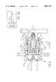
- FIG. 1is a schematic illustration showing a preferred embodiment of the invention in its neutral non-activated mode
- FIG. 2is a schematic illustration showing a preferred embodiment of the invention operating in its mode for feeding gaseous fuel
- FIG. 2Ais a schematic illustration of the pulsating voltage input which drives the armature to the position shown in FIG.2;
- FIG. 3is a schematic illustration showing the preferred embodiment operating in its mode for feeding liquid fuel
- FIG; 3Ais a schematic illustration of the pulsating input which drives the armature to the position shown in FIG,3.
- FIG. 1a preferred embodiment of the invention is illustrated. As shown in this Figure, the device is in a neutral mode with neither the liquid or gaseous fuel feeds being activated.
- the deviceis housed in a receptacle 15. Fixedly mounted in the housing is a coil assembly 8 which has pole faces 9.
- a permanent magnet cylindrical armature 7is slidably mounted within the tubular coil.
- An O-ring 6is mounted in a groove on the outer wall of the armature to provide a fluid tight seal between the opposite ends of the armature.
- a first valve 4is attached to pintle 16 which is slidably mounted in fixed bearing member 20.
- Spring 10is positioned between bearing member 20 and ring member 16a, which is fixed attached to the pintle. The spring thus urges the pintle towards armature 7 and draws valve 7 tightly against its seat 22 to maintain the valve in a closed position.
- Pintle 17is slidably mounted in fixed sleeve 27.
- the pintleis fixedly attached to a wall of the armature at one end thereof and abuts against valve 5, at the other end thereof.
- the armatureis made of a permanent magnetic material such as selenium-cobalt. In the absence of an electrical input signal, the armature is held in the center of the coil by the armature's permanent magnetic field which tends to produce a net centering force as well as by the springs 10 and 11.
- Spring 11 mounted within valve 5urges the valve to a closed position against valve seat 30.
- Gaseous fuel(propane, butane), as to be explained in connection with FIG.2,is fed into the injector from fuel rail 2 through valve 5 while liquid fuel(gasoline) is fed into the injector from fuel rail 1 through valve 4.
- Control signals for operating the deviceare fed from electronic control 33, which may comprise a conventional computerized injection control, into the injector through electrical pin connector 3.
- FIG.2 and 2Athe use of the device of the invention in feeding gaseous fuel through the injector is illustrated.
- electrical pulsating signals 12as shown in FIG. 2A, which in this case are negative, are fed through electrical pin connector 3 to coil 8.
- These negatively polarized signalscause armature 7 to move to the right(as indicated by arrow “A"), thereby driving pintle 17 against valve 5 to drive this valve off its seat.
- Valve 5thereby opens and allows gaseous fuel from gas fuel rail 2 to pass into the injector and through the passageways surrounding the coil and finally out the fuel metering orifice 13, as indicated by arrows 18.
- FIGS. 3 and 3Athe system is shown in its mode for delivering liquid fuel such as gasoline.
- electrical pulses 12are positive in polarity and are fed through electrical connector 3 to coil 8.
- the armaturemoves towards the left(as indicated by arrow "B") driving pintle 16, which is connected to valve 4, so as to unseat the valve and bring it to an open position against the spring action of spring 10.
- Gasolinenow is fed from gasoline fuel rail 1 through metering orifice 14 and out of the injector through valve 4, as indicated by arrows 19.
- the design of the electrical injector driveris arranged as a reversible polarity "peak and hold" driver; i.e. the driver form is generally similar to an H-bridge configuration, but one where the initial current shape allows the current to rise freely for a short duration approximately equal to the injector opening time, and then the current is clamped at a lower value for the rest of the pulse sufficient to just hold the valve being operated open. In this manner, it is possible to instantaneously change, pulse by pulse, from one fuel to the other, and back again as may be required.
Landscapes
- Engineering & Computer Science (AREA)
- Chemical & Material Sciences (AREA)
- Combustion & Propulsion (AREA)
- Mechanical Engineering (AREA)
- General Engineering & Computer Science (AREA)
- Oil, Petroleum & Natural Gas (AREA)
- Chemical Kinetics & Catalysis (AREA)
- General Chemical & Material Sciences (AREA)
- Analytical Chemistry (AREA)
- Physics & Mathematics (AREA)
- Electromagnetism (AREA)
- Fuel-Injection Apparatus (AREA)
Abstract
Description
Claims (6)
Priority Applications (1)
| Application Number | Priority Date | Filing Date | Title |
|---|---|---|---|
| US08/927,190US5887799A (en) | 1997-09-11 | 1997-09-11 | Dual fuel injector |
Applications Claiming Priority (1)
| Application Number | Priority Date | Filing Date | Title |
|---|---|---|---|
| US08/927,190US5887799A (en) | 1997-09-11 | 1997-09-11 | Dual fuel injector |
Publications (1)
| Publication Number | Publication Date |
|---|---|
| US5887799Atrue US5887799A (en) | 1999-03-30 |
Family
ID=25454351
Family Applications (1)
| Application Number | Title | Priority Date | Filing Date |
|---|---|---|---|
| US08/927,190Expired - LifetimeUS5887799A (en) | 1997-09-11 | 1997-09-11 | Dual fuel injector |
Country Status (1)
| Country | Link |
|---|---|
| US (1) | US5887799A (en) |
Cited By (25)
| Publication number | Priority date | Publication date | Assignee | Title |
|---|---|---|---|---|
| WO2001038714A1 (en)* | 1999-11-25 | 2001-05-31 | Sybele Technologie Sarl | Low pressure gas electromagnetic injector |
| WO2002012713A1 (en)* | 2000-08-10 | 2002-02-14 | Robert Bosch Gmbh | Fuel injection valve |
| US6431471B2 (en)* | 1999-12-10 | 2002-08-13 | Daimlerchrysler Ag | Bi-fuel injector, in particular for combustion engines, and method of injection |
| US6494190B1 (en) | 2000-08-04 | 2002-12-17 | Siemens Automotive Corporation | Bi-fuel gasoline and low pressure gas fuel system and method of operation |
| US20030029415A1 (en)* | 2000-07-18 | 2003-02-13 | Andreas Pfaeffle | Method and device for controlling an internal combustion engine |
| US20030065703A1 (en)* | 2001-10-02 | 2003-04-03 | Justin Aborn | Automated server replication |
| US20040025832A1 (en)* | 2001-09-28 | 2004-02-12 | Oswald Baasch | Fuel injector nozzle adapter |
| US20040031468A1 (en)* | 2002-08-14 | 2004-02-19 | Poola Ramesh B. | Hybrid fuel injection system |
| US20040139944A1 (en)* | 2003-01-06 | 2004-07-22 | Hitachi, Ltd. | Method and device for controlling fuel injection in the bi-fuel internal combustion engine |
| WO2004042221A3 (en)* | 2002-11-04 | 2004-09-23 | Holley Performance Products | Fuel injector nozzle adapter |
| US6830034B2 (en) | 2000-02-07 | 2004-12-14 | Siemens Automotive Corporation | Fuel injector and fuel rail check valves |
| EP1629190A4 (en)* | 2003-04-10 | 2006-11-15 | Alexander Chu | Vaporized fuel injection system and method |
| US20070017492A1 (en)* | 2005-07-22 | 2007-01-25 | Oswald Baasch | Intake manifold plate adapter |
| US20070169749A1 (en)* | 2003-08-18 | 2007-07-26 | Robert Bosch Gmbh | Fuel-injection system and method for injecting fuel |
| US20090178651A1 (en)* | 2008-01-15 | 2009-07-16 | Allan Roy Gale | System and method to control fuel vaporization |
| US7584744B2 (en)* | 2006-11-30 | 2009-09-08 | Institut Francais Du Patrole | Internal-combustion and burnt gas scavenging supercharged engine with at least two intake means |
| CN101784783A (en)* | 2007-08-10 | 2010-07-21 | 罗伯特·博世有限公司 | Actuator for an internal combustion engine and method for operating an actuator |
| US20110017174A1 (en)* | 2009-07-23 | 2011-01-27 | Ford Global Technologies, Llc | Engine with gaseous and/or liquid fuel injector |
| US8807256B2 (en) | 2012-11-21 | 2014-08-19 | Trilogy Engineered Solutions, LLC | Methods and systems for compressed natural gas (CNG) |
| US8991423B2 (en) | 2010-05-10 | 2015-03-31 | Go Natural Cng, Llc | Fuel interface modules and related systems and methods |
| USD759229S1 (en) | 2013-11-20 | 2016-06-14 | Worthington Industries | Fuel tank frame assembly |
| US9366195B2 (en) | 2012-06-21 | 2016-06-14 | Westport Power Inc. | Fuel injection valve and method of actuating |
| US9567918B2 (en) | 2010-05-10 | 2017-02-14 | Go Natural Cng, Llc | Bi-fuel control systems for automotive vehicles and related methods |
| US9850845B2 (en) | 2011-12-07 | 2017-12-26 | Agility Fuel Systems, Inc. | Systems and methods for monitoring and controlling fuel systems |
| WO2025153147A1 (en)* | 2024-01-18 | 2025-07-24 | Schaeffler Technologies AG & Co. KG | Gas injector for an internal combustion engine |
Citations (8)
| Publication number | Priority date | Publication date | Assignee | Title |
|---|---|---|---|---|
| US1769910A (en)* | 1925-02-27 | 1930-07-01 | Westinghouse Electric & Mfg Co | Electropneumatic time-element relay |
| US3215352A (en)* | 1964-06-02 | 1965-11-02 | Jr Daniel Meraz | Bi-propellant metering and injecting valve |
| US4646976A (en)* | 1985-03-21 | 1987-03-03 | Robert Bosch Gmbh | Magnetic valve, in particular a fuel quantity control valve |
| US4742801A (en)* | 1987-08-13 | 1988-05-10 | Erik Kelgard | Dual fuel mobil engine system |
| US4925252A (en)* | 1987-12-30 | 1990-05-15 | Hee Nam Y | Automobile brake system |
| US4966103A (en)* | 1989-11-09 | 1990-10-30 | Cooper Industries, Inc. | Combustion system for dual fuel engine |
| USRE34261E (en)* | 1981-11-06 | 1993-05-25 | Solenoid valve | |
| US5400970A (en)* | 1992-11-24 | 1995-03-28 | Fev Motorentechnik Gmbh & Co. Kg | Device for the combined blowoff of fuel and air |
- 1997
- 1997-09-11USUS08/927,190patent/US5887799A/ennot_activeExpired - Lifetime
Patent Citations (8)
| Publication number | Priority date | Publication date | Assignee | Title |
|---|---|---|---|---|
| US1769910A (en)* | 1925-02-27 | 1930-07-01 | Westinghouse Electric & Mfg Co | Electropneumatic time-element relay |
| US3215352A (en)* | 1964-06-02 | 1965-11-02 | Jr Daniel Meraz | Bi-propellant metering and injecting valve |
| USRE34261E (en)* | 1981-11-06 | 1993-05-25 | Solenoid valve | |
| US4646976A (en)* | 1985-03-21 | 1987-03-03 | Robert Bosch Gmbh | Magnetic valve, in particular a fuel quantity control valve |
| US4742801A (en)* | 1987-08-13 | 1988-05-10 | Erik Kelgard | Dual fuel mobil engine system |
| US4925252A (en)* | 1987-12-30 | 1990-05-15 | Hee Nam Y | Automobile brake system |
| US4966103A (en)* | 1989-11-09 | 1990-10-30 | Cooper Industries, Inc. | Combustion system for dual fuel engine |
| US5400970A (en)* | 1992-11-24 | 1995-03-28 | Fev Motorentechnik Gmbh & Co. Kg | Device for the combined blowoff of fuel and air |
Cited By (52)
| Publication number | Priority date | Publication date | Assignee | Title |
|---|---|---|---|---|
| WO2001038714A1 (en)* | 1999-11-25 | 2001-05-31 | Sybele Technologie Sarl | Low pressure gas electromagnetic injector |
| FR2801642A1 (en)* | 1999-11-25 | 2001-06-01 | Sybele Technologie | Gas injector for engine cylinder includes damping ring supporting closure element to prevent kickback of injector |
| US6431471B2 (en)* | 1999-12-10 | 2002-08-13 | Daimlerchrysler Ag | Bi-fuel injector, in particular for combustion engines, and method of injection |
| US6830034B2 (en) | 2000-02-07 | 2004-12-14 | Siemens Automotive Corporation | Fuel injector and fuel rail check valves |
| US20030029415A1 (en)* | 2000-07-18 | 2003-02-13 | Andreas Pfaeffle | Method and device for controlling an internal combustion engine |
| US6752126B2 (en)* | 2000-07-18 | 2004-06-22 | Robert Bosch Gmbh | Method and device for controlling an internal combustion engine |
| US6494190B1 (en) | 2000-08-04 | 2002-12-17 | Siemens Automotive Corporation | Bi-fuel gasoline and low pressure gas fuel system and method of operation |
| US6896209B2 (en) | 2000-08-10 | 2005-05-24 | Robert Bosch Gmbh | Fuel injection valve |
| WO2002012713A1 (en)* | 2000-08-10 | 2002-02-14 | Robert Bosch Gmbh | Fuel injection valve |
| US20040025832A1 (en)* | 2001-09-28 | 2004-02-12 | Oswald Baasch | Fuel injector nozzle adapter |
| US6997401B2 (en) | 2001-09-28 | 2006-02-14 | Holley Performance Products, Inc. | Fuel injector nozzle adapter |
| US6913210B2 (en) | 2001-09-28 | 2005-07-05 | Holley Performance Products | Fuel injector nozzle adapter |
| US20040139950A1 (en)* | 2001-09-28 | 2004-07-22 | Flynn Douglas Joseph | Fuel injector nozzle adapter |
| US6901888B2 (en) | 2001-09-28 | 2005-06-07 | Holley Performance Products | Fuel injector nozzle adapter |
| US6837228B2 (en)* | 2001-09-28 | 2005-01-04 | Holley Performance Products | Fuel injector nozzle adapter |
| US20030065703A1 (en)* | 2001-10-02 | 2003-04-03 | Justin Aborn | Automated server replication |
| US20040031468A1 (en)* | 2002-08-14 | 2004-02-19 | Poola Ramesh B. | Hybrid fuel injection system |
| US7077101B2 (en)* | 2002-08-14 | 2006-07-18 | Electro-Motive Diesel, Inc. | Hybrid fuel injection system |
| US20070095327A1 (en)* | 2002-08-14 | 2007-05-03 | Poola Ramesh B | Hybrid fuel injection system |
| WO2004042221A3 (en)* | 2002-11-04 | 2004-09-23 | Holley Performance Products | Fuel injector nozzle adapter |
| GB2409239A (en)* | 2002-11-04 | 2005-06-22 | Holley Performance Products Inc | Fuel injector nozzle adapter |
| GB2409239B (en)* | 2002-11-04 | 2006-04-05 | Holley Performance Products Inc | Fuel injector nozzle adapter |
| US20040139944A1 (en)* | 2003-01-06 | 2004-07-22 | Hitachi, Ltd. | Method and device for controlling fuel injection in the bi-fuel internal combustion engine |
| EP1629190A4 (en)* | 2003-04-10 | 2006-11-15 | Alexander Chu | Vaporized fuel injection system and method |
| CN100467849C (en)* | 2003-04-10 | 2009-03-11 | 亚历山大·初 | Vaporized fuel injection system and method |
| US20070169749A1 (en)* | 2003-08-18 | 2007-07-26 | Robert Bosch Gmbh | Fuel-injection system and method for injecting fuel |
| US7523740B2 (en)* | 2003-08-18 | 2009-04-28 | Robert Bosch Gmbh | Fuel-injection system and method for injecting fuel |
| US20070017492A1 (en)* | 2005-07-22 | 2007-01-25 | Oswald Baasch | Intake manifold plate adapter |
| US7533661B2 (en) | 2005-07-22 | 2009-05-19 | Holley Performance Products, Inc. | Intake manifold plate adapter |
| US7584744B2 (en)* | 2006-11-30 | 2009-09-08 | Institut Francais Du Patrole | Internal-combustion and burnt gas scavenging supercharged engine with at least two intake means |
| CN101784783A (en)* | 2007-08-10 | 2010-07-21 | 罗伯特·博世有限公司 | Actuator for an internal combustion engine and method for operating an actuator |
| US20090178651A1 (en)* | 2008-01-15 | 2009-07-16 | Allan Roy Gale | System and method to control fuel vaporization |
| US7681558B2 (en)* | 2008-01-15 | 2010-03-23 | Ford Global Technologies, Llc | System and method to control fuel vaporization |
| CN101487429B (en)* | 2008-01-15 | 2012-10-24 | 福特环球技术公司 | System and method to control fuel vaporization |
| US8166956B2 (en)* | 2009-07-23 | 2012-05-01 | Ford Global Technologies, Llc | Engine with gaseous and/or liquid fuel injector |
| US20110017174A1 (en)* | 2009-07-23 | 2011-01-27 | Ford Global Technologies, Llc | Engine with gaseous and/or liquid fuel injector |
| US8342158B2 (en) | 2009-07-23 | 2013-01-01 | Ford Global Technologies, Llc | Engine with gaseous and/or liquid fuel injector |
| US8991423B2 (en) | 2010-05-10 | 2015-03-31 | Go Natural Cng, Llc | Fuel interface modules and related systems and methods |
| US9353712B2 (en) | 2010-05-10 | 2016-05-31 | Go Natural Cng, Llc | Fuel interface modules and related systems and methods |
| US9567918B2 (en) | 2010-05-10 | 2017-02-14 | Go Natural Cng, Llc | Bi-fuel control systems for automotive vehicles and related methods |
| US10865732B2 (en) | 2011-12-07 | 2020-12-15 | Agility Fuel Systems Llc | Systems and methods for monitoring and controlling fuel systems |
| US10215127B2 (en) | 2011-12-07 | 2019-02-26 | Agility Fuel Systems Llc | Systems and methods for monitoring and controlling fuel systems |
| US9850845B2 (en) | 2011-12-07 | 2017-12-26 | Agility Fuel Systems, Inc. | Systems and methods for monitoring and controlling fuel systems |
| US9366195B2 (en) | 2012-06-21 | 2016-06-14 | Westport Power Inc. | Fuel injection valve and method of actuating |
| US9358877B2 (en) | 2012-11-21 | 2016-06-07 | Worthington Industries | Methods and systems for compressed natural gas (CNG) |
| US9086187B2 (en) | 2012-11-21 | 2015-07-21 | Trilogy Engineered Solutions, LLC | Methods and systems for compressed natural gas (CNG) |
| US9855841B2 (en) | 2012-11-21 | 2018-01-02 | Worthington Industries, Inc. | Methods and systems for compressed natural gas (CNG) |
| US8915322B2 (en) | 2012-11-21 | 2014-12-23 | Trilogy Engineered Solutions, LLC | Methods and systems for compressed natural gas (CNG) system |
| US8807256B2 (en) | 2012-11-21 | 2014-08-19 | Trilogy Engineered Solutions, LLC | Methods and systems for compressed natural gas (CNG) |
| US10906395B2 (en) | 2012-11-21 | 2021-02-02 | Worthington Industries Inc. | Methods and systems for compressed natural gas (CNG) |
| USD759229S1 (en) | 2013-11-20 | 2016-06-14 | Worthington Industries | Fuel tank frame assembly |
| WO2025153147A1 (en)* | 2024-01-18 | 2025-07-24 | Schaeffler Technologies AG & Co. KG | Gas injector for an internal combustion engine |
Similar Documents
| Publication | Publication Date | Title |
|---|---|---|
| US5887799A (en) | Dual fuel injector | |
| US5758865A (en) | Fuel injection valve and engine including the same | |
| EP0803026B1 (en) | Method and systems for injection valve controller | |
| US4777925A (en) | Combined fuel injection-spark ignition apparatus | |
| US4524948A (en) | Electrically controlled pressure transducer valve | |
| JPH01224454A (en) | High pressure fuel injection device of engine | |
| US4354640A (en) | Electromagnetically actuatable valve | |
| JPH045242B2 (en) | ||
| WO1996017167A9 (en) | Method and systems for injection valve controller | |
| US5004154A (en) | High pressure fuel injection device for engine | |
| US6807943B2 (en) | Motor vehicle fuel injection system with a high flow control valve | |
| GB2150978A (en) | Electromagnetic fuel injection valve | |
| US5104046A (en) | Fuel injection having a single solenoid | |
| US4561629A (en) | Solenoid valve | |
| US4925112A (en) | Fuel injection | |
| US6752333B2 (en) | Fuel injection valve | |
| WO1999044275A1 (en) | Motorized flow rate control valve | |
| EP1336747A2 (en) | Electrical injector for gaseous fuel | |
| JP4134978B2 (en) | Fuel injection device | |
| JP4229048B2 (en) | Fuel injection device and adjustment method | |
| NL8003537A (en) | DEVICE FOR SHIFTING A CARBURETTOR OF AN INTERNAL COMBUSTION ENGINE. | |
| US4216752A (en) | Spill valve for a fluid control system | |
| EP3426957B1 (en) | Injector for a system for feeding gas fuel to an internal combustion engine | |
| JPH04232376A (en) | Fuel injection device | |
| JPS6111450A (en) | Electromagnetic fuel injection valve |
Legal Events
| Date | Code | Title | Description |
|---|---|---|---|
| AS | Assignment | Owner name:IMPCO TECHNOLOGIES, INC., CALIFORNIA Free format text:ASSIGNMENT OF ASSIGNORS INTEREST;ASSIGNOR:SMITH, DAVID H.;REEL/FRAME:009056/0898 Effective date:19980213 | |
| STCF | Information on status: patent grant | Free format text:PATENTED CASE | |
| AS | Assignment | Owner name:QUANTUM FUEL SYSTEMS TECHNOLOGIES WORLDWIDE, INC., Free format text:ASSIGNMENT OF ASSIGNORS INTEREST;ASSIGNOR:IMPCO TECHNOLOGIES, INC.;REEL/FRAME:012991/0598 Effective date:20020722 | |
| REMI | Maintenance fee reminder mailed | ||
| FPAY | Fee payment | Year of fee payment:4 | |
| SULP | Surcharge for late payment | ||
| FEPP | Fee payment procedure | Free format text:PAT HOLDER NO LONGER CLAIMS SMALL ENTITY STATUS, ENTITY STATUS SET TO UNDISCOUNTED (ORIGINAL EVENT CODE: STOL); ENTITY STATUS OF PATENT OWNER: SMALL ENTITY | |
| FPAY | Fee payment | Year of fee payment:8 | |
| AS | Assignment | Owner name:WB QT, LLC, MINNESOTA Free format text:SECURITY AGREEMENT;ASSIGNOR:QUANTUM FUEL SYSTEMS TECHNOLOGIES WORLDWIDE;REEL/FRAME:020325/0389 Effective date:20070131 | |
| FEPP | Fee payment procedure | Free format text:PAT HOLDER CLAIMS SMALL ENTITY STATUS, ENTITY STATUS SET TO SMALL (ORIGINAL EVENT CODE: LTOS); ENTITY STATUS OF PATENT OWNER: SMALL ENTITY | |
| FPAY | Fee payment | Year of fee payment:12 | |
| AS | Assignment | Owner name:DOUGLAS, KEVIN, CALIFORNIA Free format text:SECURITY AGREEMENT;ASSIGNOR:QUANTUM FUEL SYSTEMS TECHNOLOGIES WORLDWIDE, INC.;REEL/FRAME:031239/0968 Effective date:20130918 | |
| AS | Assignment | Owner name:DOUGLAS ACQUISITIONS LLC, CALIFORNIA Free format text:SECURITY INTEREST;ASSIGNOR:QUANTUM FUEL SYSTEMS TECHNOLOGIES WORLDWIDE, INC.;REEL/FRAME:038660/0552 Effective date:20160510 | |
| AS | Assignment | Owner name:DOUGLAS ACQUISITIONS LLC, CALIFORNIA Free format text:ASSIGNMENT OF ASSIGNORS INTEREST;ASSIGNOR:QUANTUM FUEL SYSTEMS TECHNOLOGIES WORLDWIDE, INC.;REEL/FRAME:039162/0646 Effective date:20160713 | |
| AS | Assignment | Owner name:QUANTUM FUEL SYSTEMS LLC, CALIFORNIA Free format text:ASSIGNMENT OF ASSIGNORS INTEREST;ASSIGNOR:DOUGLAS ACQUISITIONS LLC;REEL/FRAME:040309/0651 Effective date:20161111 |