US5887690A - Clutch arrangement - Google Patents
Clutch arrangementDownload PDFInfo
- Publication number
- US5887690A US5887690AUS08/732,428US73242896AUS5887690AUS 5887690 AUS5887690 AUS 5887690AUS 73242896 AUS73242896 AUS 73242896AUS 5887690 AUS5887690 AUS 5887690A
- Authority
- US
- United States
- Prior art keywords
- clutch
- cylinder
- piston
- balancing chamber
- disc
- Prior art date
- Legal status (The legal status is an assumption and is not a legal conclusion. Google has not performed a legal analysis and makes no representation as to the accuracy of the status listed.)
- Expired - Lifetime
Links
- 230000005540biological transmissionEffects0.000description3
- 230000004323axial lengthEffects0.000description1
- 230000000903blocking effectEffects0.000description1
- 238000010276constructionMethods0.000description1
- 230000001419dependent effectEffects0.000description1
- 230000018109developmental processEffects0.000description1
- 230000001050lubricating effectEffects0.000description1
- 238000007789sealingMethods0.000description1
Images

Classifications
- F—MECHANICAL ENGINEERING; LIGHTING; HEATING; WEAPONS; BLASTING
- F16—ENGINEERING ELEMENTS AND UNITS; GENERAL MEASURES FOR PRODUCING AND MAINTAINING EFFECTIVE FUNCTIONING OF MACHINES OR INSTALLATIONS; THERMAL INSULATION IN GENERAL
- F16D—COUPLINGS FOR TRANSMITTING ROTATION; CLUTCHES; BRAKES
- F16D25/00—Fluid-actuated clutches
- F16D25/06—Fluid-actuated clutches in which the fluid actuates a piston incorporated in, i.e. rotating with the clutch
- F16D25/062—Fluid-actuated clutches in which the fluid actuates a piston incorporated in, i.e. rotating with the clutch the clutch having friction surfaces
- F16D25/063—Fluid-actuated clutches in which the fluid actuates a piston incorporated in, i.e. rotating with the clutch the clutch having friction surfaces with clutch members exclusively moving axially
- F16D25/0635—Fluid-actuated clutches in which the fluid actuates a piston incorporated in, i.e. rotating with the clutch the clutch having friction surfaces with clutch members exclusively moving axially with flat friction surfaces, e.g. discs
- F16D25/0638—Fluid-actuated clutches in which the fluid actuates a piston incorporated in, i.e. rotating with the clutch the clutch having friction surfaces with clutch members exclusively moving axially with flat friction surfaces, e.g. discs with more than two discs, e.g. multiple lamellae
- F—MECHANICAL ENGINEERING; LIGHTING; HEATING; WEAPONS; BLASTING
- F16—ENGINEERING ELEMENTS AND UNITS; GENERAL MEASURES FOR PRODUCING AND MAINTAINING EFFECTIVE FUNCTIONING OF MACHINES OR INSTALLATIONS; THERMAL INSULATION IN GENERAL
- F16D—COUPLINGS FOR TRANSMITTING ROTATION; CLUTCHES; BRAKES
- F16D25/00—Fluid-actuated clutches
- F16D25/10—Clutch systems with a plurality of fluid-actuated clutches
- F—MECHANICAL ENGINEERING; LIGHTING; HEATING; WEAPONS; BLASTING
- F16—ENGINEERING ELEMENTS AND UNITS; GENERAL MEASURES FOR PRODUCING AND MAINTAINING EFFECTIVE FUNCTIONING OF MACHINES OR INSTALLATIONS; THERMAL INSULATION IN GENERAL
- F16D—COUPLINGS FOR TRANSMITTING ROTATION; CLUTCHES; BRAKES
- F16D21/00—Systems comprising a plurality of actuated clutches
- F16D21/02—Systems comprising a plurality of actuated clutches for interconnecting three or more shafts or other transmission members in different ways
- F16D21/06—Systems comprising a plurality of actuated clutches for interconnecting three or more shafts or other transmission members in different ways at least two driving shafts or two driven shafts being concentric
- F16D2021/0661—Hydraulically actuated multiple lamellae clutches
Definitions
- the inventionconcerns a clutch arrangement according to the preamble of the first claim.
- a clutch in disc designconsists of one first cylinder having outer discs, one second cylinder having inner discs, one piston and one resetting member such as a plate spring.
- both cylindersare provided with axially extending grooves so that the discs are axially movable through the piston.
- the torqueis transmitted from the cylinder to the disc in a form-locking manner, such as by a dovetail section.
- the clutchengages by the piston pressing the discs against an end stop.
- the force for adjusting the pistonis produced by a pressure medium.
- the clutchdisengages when the force of the pressure medium is eliminated.
- the resetting membermoves the piston back to its initial position. Thereby the frictional contact of the inner and outer discs is removed.
- a speed-dependent distribution of the pressure mediumexists by virtue of centrifugal force resulting as a disturbance variable with an additional axial force component which is superimposed in the direction of force of the piston. Said disturbance variable becomes effective in the engaging and disengaging operations of the piston or of the clutch.
- a publicationnosbesetting 5 HP 30, pages 2, of ZF Getriebe GmbH Saarbrucken, March 1993,has disclosed an automatic transmission having pressure-balanced clutches.
- the pressure balanceacts as compensation for the disturbance variable produced by centrifugal force.
- the disturbance variableis compensated by loading a second chamber with pressure medium.
- the force resultingis equal in magnitude to the disturbance variable, with an opposed and directional force so that both forces neutralize themselves.
- Said second chambercomprises the piston, one disc stationary in an axial direction, and the resetting member.
- the publicationalso shows a clutch arrangement having two input clutches disposed in parallel.
- the second cylinder of the outer input clutchis radially disposed around a third clutch.
- a disadvantageis that the arrangement requires a large axial length.
- An advantage of the present inventionis based on providing a simpler practical solution.
- the problemis solved by having a first clutch radially disposed around a second clutch where a balancing chamber of the first clutch is formed by the piston of the first clutch and the first cylinder of the second clutch.
- the first cylinder of the first and second clutchesare driven by the same shaft.
- the advantage obtained herebyis that the piston of the first clutch can be sealed relative to the first cylinder of the second clutch by a simple sealing member, such as an O-ring.
- a third clutchis situated radially around a fourth clutch so that the second cylinder of the fourth clutch is connected with the first cylinder of the first clutch and that the second cylinder of the third clutch, along with the first cylinder of the fourth clutch, make up a combined part.
- the balancing chamber of the first clutch and the balancing chamber of the second clutchare connected with each other.
- the balancing chambers of both clutchesare filled via a common aperture.
- this arrangementoffers a special advantage. Reciprocally means that the first clutch disengages and at the same time the second clutch engages or vice versa. If the first clutch engages, for example, the volume of the balancing chamber become reduced. A volume of the pressure medium contained therein is thus transported to the balancing chamber of the disengaged second clutch.
- the second clutchis additionally filled with pressure medium via a common aperture. A pressure level thus builds up more quickly in the balancing chamber of the second clutch. The force resulting from said pressure level has the same force direction as the resetting member. The piston is thus more quickly returned to its initial position. The clutch disengages more quickly.
- the feed apertureconstitutes the overflow aperture.
- the advantage obtained herebyis that the overflow edge of the balancing chambers is near the shaft center.
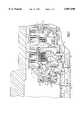
- FIG. 1is a longitudinal section of a first clutch arrangement
- FIG. 2is a longitudinal section of a second clutch arrangement.
- FIG. 1a first clutch arrangement, comprised of one first clutch 4 and one second clutch 5, is shown.
- the clutches 4 and 5are supported in a transmission housing 1.
- the first clutch 4is radially disposed around the second clutch 5.
- the first clutch 4is composed of one first cylinder 6 with outer discs 7, one second cylinder 8 with inner discs 9, one piston 10 and one resetting member 12, shown as a plate spring.
- the second clutch 5consists of one first cylinder 13 with outer discs 14, one second cylinder 15 with inner discs 16, one piston 17, one resetting member 27 and one disc 28.
- the disc 28is stationary in an axial direction.
- one first shaft 2drives the first cylinders 6 and 13 of both clutches 4 and 5.
- the first clutch 4is driven off of a second shaft 3, the second clutch 5 is driven off of a third shaft 23.
- the first clutch 4comprises a chamber 26 and a first balancing chamber 19.
- the chamber 26is formed by the piston 10 and the first cylinder 6.
- the first balancing chamber 19is formed by the piston 10 and the first cylinder 13 of the second clutch 5.
- a chamber 29 and a second balancing chamber 20belong to the second clutch 5.
- the chamber 29is formed by the first cylinder 13 of the second clutch 5 and by the piston 17.
- the second balancing chamber 20is formed by the piston 17 and the disc 28. If chamber 26 or 29 is filled with a pressure medium via respective inlets 11 and 18, it moves in an axial direction as result of the force on the piston 10 or 17, resulting in engagement of the clutch 4 or 5.
- the clutches 4 of 5disengage when the chamber 26 or 29 is emptied.
- a residual column of the pressure mediumremains in the chamber 26 or 29.
- Said residual volumeexerts an axial force upon the piston 10 or 17.
- Said axial forceis directed opposite to the directional force of the resetting member 12 or 27, resulting in a delay in the disengagement of the first clutch 4 or second clutch 5.
- This disturbance variableis compensated by a corresponding pressure level appearing in the first or second balancing chamber 19 or 20.
- the pressure mediumis fed to both balancing chambers via respective inlets 24 and 25.
- the overflow edgedetermines the pressure level.
- the balancing chambersare supplied with pressure medium via an oil-supply system 32 such as a lubricating system.
- the size of the feed flowis determined by the diameter of the aperture 22.
- FIG. 1shows an embodiment where each one of the two balancing chambers 19 and 20 has its own overflow edge 31 and its own aperture 22 for oil supply.
- FIG. 1shows a third clutch 35 and a fourth clutch 36.
- the third clutch 35is disposed radially around the fourth clutch 36.
- the second cylinder 38 of the third clutch 35is also the first cylinder of the fourth clutch 36.
- the second cylinder 39 of the fourth clutch 36is connected with the first cylinder 6 of the first clutch 4.
- the first cylinder 37 of the third clutch 35leads to a shaft, not shown.
- FIG. 2shows a second embodiment of the clutch arrangement.
- both balancing chambers 19 and 20are interconnected by the inlets 24, 25 and hole 30.
- the common overflow edge 31is formed by the hole 30 for both balancing chambers 19 and 20.
- the pressure mediumis fed to both balancing chambers 19 and 20 via an inlet 21 in the first shaft 2 and one aperture 22.
- the piston of the engaging clutchmoves, from its balancing chamber, the column of pressure medium contained therein into the balancing chamber of the disengaging clutch.
- the piston 10moves the volume of pressure medium from the first balancing chamber 19 via the inlet 24, hole 30 and inlet 25 to the second balancing chamber 20 of the second clutch 5.
- the volume from the inlet 21is the volume from the inlet 21.
- a corresponding pressure level in the second balancing chamber 20builds up more quickly so that the piston is returned more quickly to its initial position.
- the time for disengaging the second clutch 5diminishes.
- the blocking timeshortens during repeated shifts.
- the volume of pressure medium fed to the balancing chambers 19 and 20is not greater than the volume in a single supply, since the need of the balancing chambers 19 and 20 always appears periodically offset.
Landscapes
- Engineering & Computer Science (AREA)
- General Engineering & Computer Science (AREA)
- Mechanical Engineering (AREA)
- Hydraulic Clutches, Magnetic Clutches, Fluid Clutches, And Fluid Joints (AREA)
Abstract
Description
The invention concerns a clutch arrangement according to the preamble of the first claim.
A clutch in disc design consists of one first cylinder having outer discs, one second cylinder having inner discs, one piston and one resetting member such as a plate spring. In the area of the discs, both cylinders are provided with axially extending grooves so that the discs are axially movable through the piston. The torque is transmitted from the cylinder to the disc in a form-locking manner, such as by a dovetail section. The clutch engages by the piston pressing the discs against an end stop. For example, the force for adjusting the piston is produced by a pressure medium. The clutch disengages when the force of the pressure medium is eliminated. The resetting member moves the piston back to its initial position. Thereby the frictional contact of the inner and outer discs is removed. A speed-dependent distribution of the pressure medium exists by virtue of centrifugal force resulting as a disturbance variable with an additional axial force component which is superimposed in the direction of force of the piston. Said disturbance variable becomes effective in the engaging and disengaging operations of the piston or of the clutch.
A publicationFunktionsbeschreibung 5 HP 30, pages 2, of ZF Getriebe GmbH Saarbrucken, March 1993, has disclosed an automatic transmission having pressure-balanced clutches. The pressure balance acts as compensation for the disturbance variable produced by centrifugal force. The disturbance variable is compensated by loading a second chamber with pressure medium. The force resulting is equal in magnitude to the disturbance variable, with an opposed and directional force so that both forces neutralize themselves. Said second chamber comprises the piston, one disc stationary in an axial direction, and the resetting member. The publication also shows a clutch arrangement having two input clutches disposed in parallel. The second cylinder of the outer input clutch is radially disposed around a third clutch. A disadvantage is that the arrangement requires a large axial length.
An advantage of the present invention is based on providing a simpler practical solution.
According to the invention the problem is solved by having a first clutch radially disposed around a second clutch where a balancing chamber of the first clutch is formed by the piston of the first clutch and the first cylinder of the second clutch. By virtue of the multiple uses served by the parts, that is, the first cylinder of the second clutch is, at the same time, the disc of the first clutch, the advantage of a smaller and more compact construction is obtained. The result is a reduction in cost because the number of parts is reduced.
In one embodiment of the invention, it is proposed that the first cylinder of the first and second clutches are driven by the same shaft. The advantage obtained hereby is that the piston of the first clutch can be sealed relative to the first cylinder of the second clutch by a simple sealing member, such as an O-ring.
In another embodiment, it is proposed that a third clutch is situated radially around a fourth clutch so that the second cylinder of the fourth clutch is connected with the first cylinder of the first clutch and that the second cylinder of the third clutch, along with the first cylinder of the fourth clutch, make up a combined part.
In another embodiment of the invention it is proposed that the balancing chamber of the first clutch and the balancing chamber of the second clutch are connected with each other. The balancing chambers of both clutches are filled via a common aperture. When the gearshift state of the clutches reciprocally changes, this arrangement offers a special advantage. Reciprocally means that the first clutch disengages and at the same time the second clutch engages or vice versa. If the first clutch engages, for example, the volume of the balancing chamber become reduced. A volume of the pressure medium contained therein is thus transported to the balancing chamber of the disengaged second clutch. The second clutch is additionally filled with pressure medium via a common aperture. A pressure level thus builds up more quickly in the balancing chamber of the second clutch. The force resulting from said pressure level has the same force direction as the resetting member. The piston is thus more quickly returned to its initial position. The clutch disengages more quickly.
In development of this it is proposed that the feed aperture, at the same time, constitutes the overflow aperture. The advantage obtained hereby is that the overflow edge of the balancing chambers is near the shaft center.
The embodiments are shown in the drawings.
FIG. 1 is a longitudinal section of a first clutch arrangement; and
FIG. 2 is a longitudinal section of a second clutch arrangement.
In FIG. 1, a first clutch arrangement, comprised of onefirst clutch 4 and onesecond clutch 5, is shown.
Theclutches first clutch 4 is radially disposed around thesecond clutch 5. Thefirst clutch 4 is composed of one first cylinder 6 with outer discs 7, one second cylinder 8 with inner discs 9, onepiston 10 and one resettingmember 12, shown as a plate spring. Thesecond clutch 5 consists of onefirst cylinder 13 withouter discs 14, onesecond cylinder 15 withinner discs 16, one piston 17, one resettingmember 27 and onedisc 28. Thedisc 28 is stationary in an axial direction. In the arrangement shown, one first shaft 2 drives thefirst cylinders 6 and 13 of bothclutches first clutch 4 is driven off of a second shaft 3, thesecond clutch 5 is driven off of athird shaft 23. Thefirst clutch 4 comprises achamber 26 and afirst balancing chamber 19. Thechamber 26 is formed by thepiston 10 and the first cylinder 6. Thefirst balancing chamber 19 is formed by thepiston 10 and thefirst cylinder 13 of thesecond clutch 5. Achamber 29 and asecond balancing chamber 20 belong to thesecond clutch 5. Thechamber 29 is formed by thefirst cylinder 13 of thesecond clutch 5 and by the piston 17. Thesecond balancing chamber 20 is formed by the piston 17 and thedisc 28. Ifchamber respective inlets 11 and 18, it moves in an axial direction as result of the force on thepiston 10 or 17, resulting in engagement of theclutch clutches 4 of 5 disengage when thechamber chamber piston 10 or 17. Said axial force is directed opposite to the directional force of the resettingmember first clutch 4 orsecond clutch 5. This disturbance variable is compensated by a corresponding pressure level appearing in the first orsecond balancing chamber respective inlets supply system 32 such as a lubricating system. The size of the feed flow is determined by the diameter of theaperture 22. If the balancingchamber chambers own overflow edge 31 and itsown aperture 22 for oil supply. FIG. 1 shows a third clutch 35 and afourth clutch 36. The third clutch 35 is disposed radially around thefourth clutch 36. Thesecond cylinder 38 of the third clutch 35 is also the first cylinder of thefourth clutch 36. The second cylinder 39 of the fourth clutch 36 is connected with the first cylinder 6 of thefirst clutch 4. Thefirst cylinder 37 of the third clutch 35 leads to a shaft, not shown.
FIG. 2 shows a second embodiment of the clutch arrangement. The difference from FIG. 1 is that both balancingchambers inlets hole 30. Thecommon overflow edge 31 is formed by thehole 30 for both balancingchambers chambers aperture 22. In a reciprocal behavior of bothclutches first clutch 4 engages, for example, thepiston 10 moves the volume of pressure medium from thefirst balancing chamber 19 via theinlet 24,hole 30 andinlet 25 to thesecond balancing chamber 20 of thesecond clutch 5. In addition to said volume described above, is the volume from the inlet 21. Hereby a corresponding pressure level in thesecond balancing chamber 20 builds up more quickly so that the piston is returned more quickly to its initial position. Thereby, the time for disengaging thesecond clutch 5 diminishes. By this step, the blocking time shortens during repeated shifts. The volume of pressure medium fed to the balancingchambers chambers
Reference numerals
1 transmission housing
2 first shaft
3 second shaft
4 first clutch
5 second clutch
6 first cylinder
7 outer clutch discs
8 second cylinder
9 inner clutch discs
10 piston
11 inlet
12 resetting member
13 first cylinder
14 outer clutch discs
15 second cylinder
16 inner clutch discs
17 piston
18 inlet
19 first balancing chamber
20 second balancing chamber
21 inlet
22 aperture
23 third shaft
24 inlet
25 inlet
26 chamber
27 resetting member
28 disc
29 chamber
30 hole
31 overflow edge
32 supply system
33 overflow hole
34 overflow groove
35 third clutch
36 fourth clutch
37 first cylinder
38 second cylinder
39 second cylinder
Claims (5)
1. A clutch arrangement having at least one first clutch and at least one second clutch (4, 5), each of the at least first and second clutches comprising:
a first cylinder (6, 13) with at least one outer clutch disc (7, 14); a second cylinder (8, 15) with at least one an inner clutch disc (9, 16); a piston (10, 17) being coupled to apply an actuation force against the at least one outer clutch disc against the at least one inner clutch disc; a resetting member (12, 27) which, in an absence of an actuation force being applied by the piston (10, 17), returns the piston (10, 17) back to an initial retracted position; and a clutch balancing chamber (19, 20);
wherein the first clutch (4) is radially disposed about the second clutch (5); the at least one second clutch has a disc (28) which together with the piston (17) forms the clutch balancing chamber (20) for the at least one second clutch (5); the piston (10) of the first clutch (4) and the first cylinder (13) of the second clutch (5) form the balancing chamber (19) for the at least one first clutch (4); and each of the balancing chambers counteracts changes in a pressure of the pistons as a result of rotation of the at least one first and the at least one second clutches (4, 5).
2. The clutch arrangement according to claim 1, wherein the first cylinder (6, 13) of both the at least one first and second clutches (4, 5) are driven by one shaft (2).
3. The clutch arrangement according to claim 1, wherein a third clutch (35) is radially disposed around a fourth clutch (36), a second cylinder (39) of the fourth clutch (36) is connected with the first cylinder (6) of the at least one first clutch (4), and a second cylinder (38) of the third clutch (35), along with a first cylinder of the fourth clutch (36), form a combined drive component.
4. The clutch arrangement according to claim 1, wherein the balancing chamber (19) of the at least one first clutch (4) and the balancing chamber (20) of the at least one second clutch (5) communicated with one another and are fillable via a common aperture (22).
5. The clutch arrangement according to claim 4, wherein an inlet (24, 25) feeds the balancing chamber (19) of the at least one first clutch (4) and the balancing chamber (20) of the at least one second clutch (5) so that excess medium is removed therefrom via one of an overflow hole (33) and an overflow groove (34).
Applications Claiming Priority (3)
| Application Number | Priority Date | Filing Date | Title |
|---|---|---|---|
| DE4415664ADE4415664A1 (en) | 1994-05-04 | 1994-05-04 | Coupling arrangement |
| DE4415664.2 | 1994-05-04 | ||
| PCT/EP1995/001632WO1995030840A1 (en) | 1994-05-04 | 1995-04-28 | Clutch arrangement |
Publications (1)
| Publication Number | Publication Date |
|---|---|
| US5887690Atrue US5887690A (en) | 1999-03-30 |
Family
ID=6517236
Family Applications (1)
| Application Number | Title | Priority Date | Filing Date |
|---|---|---|---|
| US08/732,428Expired - LifetimeUS5887690A (en) | 1994-05-04 | 1995-04-28 | Clutch arrangement |
Country Status (6)
| Country | Link |
|---|---|
| US (1) | US5887690A (en) |
| EP (1) | EP0758434B1 (en) |
| JP (1) | JP3636467B2 (en) |
| KR (1) | KR100353261B1 (en) |
| DE (2) | DE4415664A1 (en) |
| WO (1) | WO1995030840A1 (en) |
Cited By (52)
| Publication number | Priority date | Publication date | Assignee | Title |
|---|---|---|---|---|
| EP1079131A1 (en)* | 1999-08-24 | 2001-02-28 | BorgWarner Inc. | Automatic transmission having nested clutch housings |
| FR2799247A1 (en)* | 1999-09-30 | 2001-04-06 | Mannesmann Sachs Ag | MULTIPLE CLUTCH SYSTEM WITH A CENTRIFUGAL FORCE PRESSURE COMPENSATION CHAMBER |
| FR2799248A1 (en)* | 1999-09-30 | 2001-04-06 | Mannesmann Sachs Ag | Multiple clutching unit for automotive vehicle, has different friction radii for the two different clutch devices |
| FR2799250A1 (en)* | 1999-09-30 | 2001-04-06 | Mannesmann Sachs Ag | MULTIPLE CLUTCH INSTALLATION WITH AT LEAST ONE PACKAGE OF LAMELLES PARTLY WITHOUT FRICTION TRIM |
| FR2799251A1 (en)* | 1999-09-30 | 2001-04-06 | Mannesmann Sachs Ag | Duplicated clutch assembly, for automobile transmission, comprises inner and outer annular clutches engaging prime mover with none or both gearbox input shafts |
| FR2799246A1 (en)* | 1999-09-30 | 2001-04-06 | Mannesmann Sachs Ag | MULTIPLE CLUTCH INSTALLATION WITH AT LEAST ONE BEARING DEVICE |
| WO2001042674A1 (en)* | 1999-12-13 | 2001-06-14 | Volvo Lastvagnar Ab | Hydraulically operated double clutch |
| FR2814516A1 (en)* | 2000-09-22 | 2002-03-29 | Valeo | Automobile gear transmission system comprises engine shaft connected through two clutches to two transmission input coaxial shafts |
| US6378675B1 (en) | 1999-09-30 | 2002-04-30 | Mannesmann Sachs Ag | Clutch device with a hydrodynamic clutch and at least two friction clutches |
| US6382382B1 (en)* | 2000-10-25 | 2002-05-07 | Ford Global Technologies, Inc. | Centrifugally balanced, pressure-operated clutch assembly |
| US6491149B1 (en) | 1999-09-30 | 2002-12-10 | Mannesmann Sachs Ag | Multiple-clutch device |
| US6499578B1 (en) | 1999-09-30 | 2002-12-31 | Mannesmann Sachs Ag | Multiple-clutch device |
| WO2003006840A1 (en)* | 2001-07-11 | 2003-01-23 | Zf Sachs Ag | Multiple clutch system, especially a double clutch system |
| US6543597B2 (en)* | 2000-03-21 | 2003-04-08 | Aisin Seiki Kabushiki Kaisha | Clutch device for an automatic transmission |
| US6595339B1 (en)* | 1999-07-13 | 2003-07-22 | Zf Friedrichshafen Ag | Variable gear ratio transmission |
| US6622839B2 (en)* | 2000-07-17 | 2003-09-23 | Mannesmann Sachs Ag | Multiple clutch arrangement |
| US20030232675A1 (en)* | 2002-06-18 | 2003-12-18 | Toyota Jidosha Kabushiki Kaisha | Power transmission interruption apparatus |
| EP1382875A1 (en)* | 2002-07-18 | 2004-01-21 | BorgWarner Inc. | Wet clutch or friction plate brake |
| US20040035666A1 (en)* | 2000-12-07 | 2004-02-26 | Wolfgang Grosspietsch | Double or multiple disk coupling device and disk arrangement therefor |
| US20040037724A1 (en)* | 2000-12-12 | 2004-02-26 | Christian Haser | Peristaltic hose pump |
| US20040077449A1 (en)* | 2002-10-16 | 2004-04-22 | Eberhard Biermann | Clutch system for a transmission |
| US6729990B1 (en) | 1999-07-13 | 2004-05-04 | Zf Friedrichshafen Ag | Automatic gearbox |
| WO2005019675A1 (en)* | 2003-07-23 | 2005-03-03 | Zf Friedrichshafen Ag | Clutch arrangement in an automatic transmission having an installation space-saving coolant supply |
| US20050067251A1 (en)* | 2003-09-30 | 2005-03-31 | Borg Warner, Inc. | Oil management system for dual clutch transmissions |
| US20050072255A1 (en)* | 2003-10-06 | 2005-04-07 | Borg Warner Inc. | Multi-clutch system with blended output system for powertrain transmissions |
| US20050082136A1 (en)* | 2003-10-11 | 2005-04-21 | Borgwarner Inc. | Hydraulic double clutch |
| US20050087420A1 (en)* | 2003-10-11 | 2005-04-28 | Borgwarner Inc. | Powertrain |
| US20050224309A1 (en)* | 2004-04-07 | 2005-10-13 | Duwel Jeffrey A | Apply piston seal for a clutch |
| US20050279605A1 (en)* | 2004-06-18 | 2005-12-22 | Henryk Sowul | Rotating torque-transmitting apparatus |
| US20060086586A1 (en)* | 2004-10-26 | 2006-04-27 | Borgwarner Inc. | Dual clutch mechanism for a transmission |
| US20080207386A1 (en)* | 2007-02-23 | 2008-08-28 | Aisin Aw Co., Ltd. | Automatic transmission |
| US20080207385A1 (en)* | 2007-02-23 | 2008-08-28 | Aisin Aw Co., Ltd. | Automatic transmission |
| US20080223685A1 (en)* | 2007-03-14 | 2008-09-18 | Raszkowski James A | Clutch exhaust assembly and method |
| US20090011892A1 (en)* | 2007-07-05 | 2009-01-08 | Aisin Aw Co., Ltd. | Automatic transmission |
| US20090020386A1 (en)* | 2005-06-07 | 2009-01-22 | Toyota Jidosha Kabushiki Kaisha | Automatic transmission including clutch devices |
| US20090211865A1 (en)* | 2005-05-17 | 2009-08-27 | Borgwarner Inc. | Dual clutch mechanism for a transmission |
| US20090250307A1 (en)* | 2008-04-04 | 2009-10-08 | Gm Global Technology Operations, Inc. | Dual apply clutch apparatus for compact electro-mechanical transmission |
| US20100044184A1 (en)* | 2008-08-22 | 2010-02-25 | Aisin Aw Co., Ltd. | Automatic transmission |
| US20100078282A1 (en)* | 2008-08-22 | 2010-04-01 | Aisin Aw Co., Ltd. | Automatic transmission |
| US20100320050A1 (en)* | 2006-11-21 | 2010-12-23 | Exedy Corporation | Multiple clutch device |
| US20110203896A1 (en)* | 2010-02-22 | 2011-08-25 | Twin Disc, Inc. | Balanced Clutch System |
| US20110233024A1 (en)* | 2010-03-26 | 2011-09-29 | Honda Motor Co., Ltd. | Oil passage structure for hydraulic clutch of an engine |
| US20120214643A1 (en)* | 2011-02-21 | 2012-08-23 | Zf Friedrichshafen Ag | Method and device for actuating a shift element of an automatic transmission having a start-stop means |
| US20120217119A1 (en)* | 2011-02-24 | 2012-08-30 | Ford Global Technologies, Llc | Carrying Fluid to Balance Dams in a Servo Piston Support |
| DE102009016282B4 (en)* | 2008-04-04 | 2013-11-21 | GM Global Technology Operations LLC (n. d. Ges. d. Staates Delaware) | Double-acting coupling device for compact electromechanical gearbox |
| US8613682B2 (en)* | 2012-05-04 | 2013-12-24 | GM Global Technology Operations LLC | Rotating clutch balance fill system |
| US20140113761A1 (en)* | 2012-10-23 | 2014-04-24 | Ford Global Technologies, Llc | Clutch assembly and transmission |
| US20150001027A1 (en)* | 2012-02-02 | 2015-01-01 | Arthur Schröder | Clutch Arrangement and Sealing Element |
| CN105074251A (en)* | 2013-04-30 | 2015-11-18 | 爱信艾达株式会社 | Transmission device |
| US9222526B2 (en)* | 2012-10-23 | 2015-12-29 | Ford Global Technologies, Llc | Clutch housing and assembly |
| US20180283469A1 (en)* | 2015-08-20 | 2018-10-04 | Schaeffler Technologies AG & Co. KG | Clutch device for a hybrid drive system |
| US10895289B2 (en)* | 2019-05-07 | 2021-01-19 | Allison Transmission, Inc. | Clutch assemblies with balance cavities formed by disc springs |
Families Citing this family (26)
| Publication number | Priority date | Publication date | Assignee | Title |
|---|---|---|---|---|
| JPH08219176A (en)* | 1995-02-08 | 1996-08-27 | Jatco Corp | Clutch assembling body structure of multiple disk clutch |
| DE19921687C5 (en)* | 1999-05-12 | 2016-06-09 | Borgwarner Inc. | Multiple clutch system for a transmission |
| DE10034730B4 (en)* | 1999-09-30 | 2010-10-14 | Zf Sachs Ag | Multiple coupling device, possibly in combination with a torsional vibration damper assembly and / or an electric machine |
| DE50113312D1 (en) | 2000-07-17 | 2008-01-10 | Zf Sachs Ag | Multiple clutch device in combination with a torsional vibration damper assembly and / or an electric machine |
| DE10044493B4 (en)* | 2000-09-08 | 2012-05-03 | Zf Sachs Ag | Multiple clutch device, in particular double clutch device, for powershift transmissions |
| DE10049474A1 (en) | 2000-10-06 | 2002-04-25 | Zf Sachs Ag | coupling device |
| DE10111202B4 (en)* | 2000-12-07 | 2009-06-10 | Zf Sachs Ag | Double or multiple coupling device, and sealing concept for this |
| DE10063781C2 (en)* | 2000-12-21 | 2003-02-20 | Zf Sachs Ag | Coupling system with a clutch device operated by master cylinder |
| EP1226992B1 (en)* | 2001-01-25 | 2004-07-21 | ZF Sachs AG | Multiple clutch device adapted to be mounted in a drive train as preassembled unit |
| DE102004027088B4 (en)* | 2004-06-02 | 2009-02-05 | Borgwarner Inc., Auburn Hills | Coupling device with centrifugal force compensation device and method for compensating for a centrifugal force-induced pressure increase in a pressure chamber for an actuating piston in a coupling device |
| DE102004048068B4 (en) | 2004-10-02 | 2014-08-21 | Zf Friedrichshafen Ag | Wet multi-plate clutch |
| DE102005008971A1 (en)* | 2005-02-28 | 2006-08-31 | Zf Friedrichshafen Ag | Clutch arrangement with at least two clutches, comprising reset element also serving as sensor plate for first clutch |
| DE102005020415A1 (en)* | 2005-04-27 | 2006-11-09 | Getrag Getriebe- Und Zahnradfabrik Hermann Hagenmeyer Gmbh & Cie Kg | Drive unit for a motor vehicle |
| EP1726842B1 (en) | 2005-05-25 | 2009-09-02 | Borgwarner, Inc. | Clutch assembly with radially adjoining clutches |
| JP4754925B2 (en)* | 2005-10-11 | 2011-08-24 | 株式会社エクセディ | Double clutch device |
| DE102006008243A1 (en)* | 2006-02-22 | 2007-09-06 | Volkswagen Ag | Oil pressure supply for the dual clutch of a motor vehicle or dual clutch transmission with the aforementioned oil pressure supply |
| DE102006035649B4 (en) | 2006-07-31 | 2022-03-10 | Zf Friedrichshafen Ag | Clutch assembly for a vehicle |
| JP5165223B2 (en) | 2006-09-29 | 2013-03-21 | 本田技研工業株式会社 | Motorcycle |
| DE102006059328A1 (en) | 2006-12-16 | 2008-07-24 | Zf Friedrichshafen Ag | Coupling arrangement of a motor vehicle drive train |
| DE102007022422A1 (en) | 2007-05-10 | 2008-11-13 | Borgwarner Inc., Auburn Hills | Double clutch arrangement with piston guide element |
| US7854675B2 (en)* | 2007-06-28 | 2010-12-21 | Gm Global Technology Operations, Inc. | Hydraulic feed system for a transmission |
| DE102008060580B4 (en)* | 2008-06-03 | 2021-01-21 | Borgwarner Inc. | Multiple coupling device with two pressure equalization chambers |
| JP2010048318A (en)* | 2008-08-21 | 2010-03-04 | Mazda Motor Corp | Automatic transmission |
| JP6110249B2 (en)* | 2013-08-02 | 2017-04-05 | 株式会社ダイナックス | Hydraulic clutch |
| JP6496625B2 (en)* | 2015-07-17 | 2019-04-03 | ジヤトコ株式会社 | Wet clutch device |
| DE102018201781A1 (en)* | 2018-02-06 | 2019-08-08 | Zf Friedrichshafen Ag | coupling device |
Citations (5)
| Publication number | Priority date | Publication date | Assignee | Title |
|---|---|---|---|---|
| US4732253A (en)* | 1985-08-31 | 1988-03-22 | Mitsubishi Jidosha Kogyo Kabushiki Kaisha | Power transmission |
| US4759432A (en)* | 1986-04-02 | 1988-07-26 | Daimler-Benz Aktiengesellschaft | Pressure medium-adjusting member for the actuation of a lamelae-clutch with a lubricating valve |
| US4957195A (en)* | 1988-09-27 | 1990-09-18 | Aisin Aw Co., Ltd. | Hydraulic device for an automatic transmission |
| US5439088A (en)* | 1992-01-30 | 1995-08-08 | Nissan Motor Co., Ltd. | Automatic transmission with passages connecting apply and cancel chambers |
| US5662198A (en)* | 1994-08-19 | 1997-09-02 | Honda Giken Kogyo Kabushiki Kaisha | Tandem type hydraulic clutch system |
Family Cites Families (2)
| Publication number | Priority date | Publication date | Assignee | Title |
|---|---|---|---|---|
| US4010833A (en)* | 1975-02-19 | 1977-03-08 | Zahnradfabrik Friedrichshafen Ag | Clutch assembly for planetary-gear trains |
| JPS5937338A (en)* | 1982-08-23 | 1984-02-29 | Nissan Motor Co Ltd | Clutch drum for multiple disc clutch device |
- 1994
- 1994-05-04DEDE4415664Apatent/DE4415664A1/ennot_activeWithdrawn
- 1995
- 1995-04-28KRKR1019960706123Apatent/KR100353261B1/ennot_activeExpired - Lifetime
- 1995-04-28USUS08/732,428patent/US5887690A/ennot_activeExpired - Lifetime
- 1995-04-28JPJP52865595Apatent/JP3636467B2/ennot_activeExpired - Lifetime
- 1995-04-28WOPCT/EP1995/001632patent/WO1995030840A1/enactiveIP Right Grant
- 1995-04-28EPEP95919362Apatent/EP0758434B1/ennot_activeExpired - Lifetime
- 1995-04-28DEDE59507579Tpatent/DE59507579D1/ennot_activeExpired - Lifetime
Patent Citations (5)
| Publication number | Priority date | Publication date | Assignee | Title |
|---|---|---|---|---|
| US4732253A (en)* | 1985-08-31 | 1988-03-22 | Mitsubishi Jidosha Kogyo Kabushiki Kaisha | Power transmission |
| US4759432A (en)* | 1986-04-02 | 1988-07-26 | Daimler-Benz Aktiengesellschaft | Pressure medium-adjusting member for the actuation of a lamelae-clutch with a lubricating valve |
| US4957195A (en)* | 1988-09-27 | 1990-09-18 | Aisin Aw Co., Ltd. | Hydraulic device for an automatic transmission |
| US5439088A (en)* | 1992-01-30 | 1995-08-08 | Nissan Motor Co., Ltd. | Automatic transmission with passages connecting apply and cancel chambers |
| US5662198A (en)* | 1994-08-19 | 1997-09-02 | Honda Giken Kogyo Kabushiki Kaisha | Tandem type hydraulic clutch system |
Cited By (98)
| Publication number | Priority date | Publication date | Assignee | Title |
|---|---|---|---|---|
| US6595339B1 (en)* | 1999-07-13 | 2003-07-22 | Zf Friedrichshafen Ag | Variable gear ratio transmission |
| US6729990B1 (en) | 1999-07-13 | 2004-05-04 | Zf Friedrichshafen Ag | Automatic gearbox |
| EP1079131A1 (en)* | 1999-08-24 | 2001-02-28 | BorgWarner Inc. | Automatic transmission having nested clutch housings |
| US6491149B1 (en) | 1999-09-30 | 2002-12-10 | Mannesmann Sachs Ag | Multiple-clutch device |
| DE10004179C5 (en)* | 1999-09-30 | 2017-06-29 | Volkswagen Ag | Multiple clutch device |
| FR2799246A1 (en)* | 1999-09-30 | 2001-04-06 | Mannesmann Sachs Ag | MULTIPLE CLUTCH INSTALLATION WITH AT LEAST ONE BEARING DEVICE |
| FR2799250A1 (en)* | 1999-09-30 | 2001-04-06 | Mannesmann Sachs Ag | MULTIPLE CLUTCH INSTALLATION WITH AT LEAST ONE PACKAGE OF LAMELLES PARTLY WITHOUT FRICTION TRIM |
| FR2812699A1 (en)* | 1999-09-30 | 2002-02-08 | Mannesmann Sachs Ag | MULTIPLE CLUTCH SYSTEM HAVING A SEALED GUIDE PISTON |
| US6523657B1 (en) | 1999-09-30 | 2003-02-25 | Mannesmann Sachs Ag | Multiple-clutch device |
| US6378675B1 (en) | 1999-09-30 | 2002-04-30 | Mannesmann Sachs Ag | Clutch device with a hydrodynamic clutch and at least two friction clutches |
| FR2799251A1 (en)* | 1999-09-30 | 2001-04-06 | Mannesmann Sachs Ag | Duplicated clutch assembly, for automobile transmission, comprises inner and outer annular clutches engaging prime mover with none or both gearbox input shafts |
| US6454074B1 (en) | 1999-09-30 | 2002-09-24 | Mannesmann Sachs Ag | Multiple-clutch device |
| US6464059B1 (en) | 1999-09-30 | 2002-10-15 | Mannesmann Sachs Ag | Multiple-clutch device |
| US6471026B1 (en)* | 1999-09-30 | 2002-10-29 | Mannesmann Sachs Ag | Multiple-clutch device |
| FR2799247A1 (en)* | 1999-09-30 | 2001-04-06 | Mannesmann Sachs Ag | MULTIPLE CLUTCH SYSTEM WITH A CENTRIFUGAL FORCE PRESSURE COMPENSATION CHAMBER |
| US6499578B1 (en) | 1999-09-30 | 2002-12-31 | Mannesmann Sachs Ag | Multiple-clutch device |
| FR2799248A1 (en)* | 1999-09-30 | 2001-04-06 | Mannesmann Sachs Ag | Multiple clutching unit for automotive vehicle, has different friction radii for the two different clutch devices |
| WO2001042674A1 (en)* | 1999-12-13 | 2001-06-14 | Volvo Lastvagnar Ab | Hydraulically operated double clutch |
| US6543597B2 (en)* | 2000-03-21 | 2003-04-08 | Aisin Seiki Kabushiki Kaisha | Clutch device for an automatic transmission |
| US6622839B2 (en)* | 2000-07-17 | 2003-09-23 | Mannesmann Sachs Ag | Multiple clutch arrangement |
| FR2814516A1 (en)* | 2000-09-22 | 2002-03-29 | Valeo | Automobile gear transmission system comprises engine shaft connected through two clutches to two transmission input coaxial shafts |
| US6382382B1 (en)* | 2000-10-25 | 2002-05-07 | Ford Global Technologies, Inc. | Centrifugally balanced, pressure-operated clutch assembly |
| US20040035666A1 (en)* | 2000-12-07 | 2004-02-26 | Wolfgang Grosspietsch | Double or multiple disk coupling device and disk arrangement therefor |
| US7114605B2 (en)* | 2000-12-07 | 2006-10-03 | Zf Sachs Ag | Double or multiple disk coupling device and disk arrangement therefor |
| US20040037724A1 (en)* | 2000-12-12 | 2004-02-26 | Christian Haser | Peristaltic hose pump |
| EP1404985B2 (en)† | 2001-07-11 | 2015-10-21 | ZF Friedrichshafen AG | Multiple clutch system, especially a double clutch system |
| WO2003006840A1 (en)* | 2001-07-11 | 2003-01-23 | Zf Sachs Ag | Multiple clutch system, especially a double clutch system |
| US20030232675A1 (en)* | 2002-06-18 | 2003-12-18 | Toyota Jidosha Kabushiki Kaisha | Power transmission interruption apparatus |
| US20040074708A1 (en)* | 2002-07-18 | 2004-04-22 | Borgwarner Inc. | Wet clutch or friction plate brake |
| US6945371B2 (en) | 2002-07-18 | 2005-09-20 | Borgwarner Inc. | Wet clutch or friction plate brake |
| EP1382875A1 (en)* | 2002-07-18 | 2004-01-21 | BorgWarner Inc. | Wet clutch or friction plate brake |
| US7001298B2 (en) | 2002-10-16 | 2006-02-21 | Zf Friedrichshafen Ag | Clutch system for a transmission |
| US20040077449A1 (en)* | 2002-10-16 | 2004-04-22 | Eberhard Biermann | Clutch system for a transmission |
| US7416069B2 (en) | 2003-07-23 | 2008-08-26 | Zf Friedrichshafen Ag | Clutch arrangement in an automatic transmission having an installation space-saving coolant supply |
| US20060289269A1 (en)* | 2003-07-23 | 2006-12-28 | Zf Friedrichshafen Ag | Clutch arrangement in an automatic transmission having an installation space-saving coolant supply |
| WO2005019675A1 (en)* | 2003-07-23 | 2005-03-03 | Zf Friedrichshafen Ag | Clutch arrangement in an automatic transmission having an installation space-saving coolant supply |
| US20050067251A1 (en)* | 2003-09-30 | 2005-03-31 | Borg Warner, Inc. | Oil management system for dual clutch transmissions |
| US20050072255A1 (en)* | 2003-10-06 | 2005-04-07 | Borg Warner Inc. | Multi-clutch system with blended output system for powertrain transmissions |
| US7171867B2 (en) | 2003-10-06 | 2007-02-06 | Borgwarner Inc. | Multi-clutch system with blended output system for powertrain transmissions |
| US20050087420A1 (en)* | 2003-10-11 | 2005-04-28 | Borgwarner Inc. | Powertrain |
| US7121392B2 (en) | 2003-10-11 | 2006-10-17 | Borgwarner Inc. | Hydraulic double clutch |
| US20050082136A1 (en)* | 2003-10-11 | 2005-04-21 | Borgwarner Inc. | Hydraulic double clutch |
| US20060022375A1 (en)* | 2004-04-07 | 2006-02-02 | Freudenberg-Nok General Partnership | Apply piston seal for a clutch |
| US7021447B2 (en)* | 2004-04-07 | 2006-04-04 | Freudenberg-Nok General Partnership | Apply piston seal for a clutch |
| US8425823B2 (en) | 2004-04-07 | 2013-04-23 | Freudenberg-Nok General Partnership | Apply piston seal for a clutch |
| US20050224309A1 (en)* | 2004-04-07 | 2005-10-13 | Duwel Jeffrey A | Apply piston seal for a clutch |
| US20050279605A1 (en)* | 2004-06-18 | 2005-12-22 | Henryk Sowul | Rotating torque-transmitting apparatus |
| US7036645B2 (en)* | 2004-06-18 | 2006-05-02 | General Motors Corporation | Rotating torque-transmitting apparatus |
| US7246692B2 (en) | 2004-10-26 | 2007-07-24 | Borgwarner Inc. | Dual clutch mechanism for a transmission |
| US20060086586A1 (en)* | 2004-10-26 | 2006-04-27 | Borgwarner Inc. | Dual clutch mechanism for a transmission |
| US8714326B2 (en)* | 2005-05-17 | 2014-05-06 | Borgwarner Inc. | Dual clutch mechanism for a transmission |
| US20090211865A1 (en)* | 2005-05-17 | 2009-08-27 | Borgwarner Inc. | Dual clutch mechanism for a transmission |
| US8281915B2 (en)* | 2005-06-07 | 2012-10-09 | Toyota Jidosha Kabushiki Kaisha | Automatic transmission including clutch devices |
| US20090020386A1 (en)* | 2005-06-07 | 2009-01-22 | Toyota Jidosha Kabushiki Kaisha | Automatic transmission including clutch devices |
| US8376108B2 (en)* | 2006-11-21 | 2013-02-19 | Exedy Corporation | Multiple clutch device |
| US20100320050A1 (en)* | 2006-11-21 | 2010-12-23 | Exedy Corporation | Multiple clutch device |
| US20080207386A1 (en)* | 2007-02-23 | 2008-08-28 | Aisin Aw Co., Ltd. | Automatic transmission |
| US7731623B2 (en)* | 2007-02-23 | 2010-06-08 | Aisin Aw Co., Ltd. | Automatic transmission |
| US7731624B2 (en)* | 2007-02-23 | 2010-06-08 | Aisin Aw Co., Ltd. | Automatic transmission |
| US20080207385A1 (en)* | 2007-02-23 | 2008-08-28 | Aisin Aw Co., Ltd. | Automatic transmission |
| EP2085635A4 (en)* | 2007-02-23 | 2011-04-20 | Aisin Aw Co | Automatic transmission |
| US7802667B2 (en)* | 2007-03-14 | 2010-09-28 | Gm Global Technology Operations, Inc. | Clutch exhaust assembly and method |
| US20080223685A1 (en)* | 2007-03-14 | 2008-09-18 | Raszkowski James A | Clutch exhaust assembly and method |
| US7862461B2 (en)* | 2007-07-05 | 2011-01-04 | Aisin Aw Co., Ltd. | Automatic transmission |
| CN101578464B (en)* | 2007-07-05 | 2012-11-14 | 爱信艾达株式会社 | Automatic transmission |
| US20090011892A1 (en)* | 2007-07-05 | 2009-01-08 | Aisin Aw Co., Ltd. | Automatic transmission |
| DE102009016282B4 (en)* | 2008-04-04 | 2013-11-21 | GM Global Technology Operations LLC (n. d. Ges. d. Staates Delaware) | Double-acting coupling device for compact electromechanical gearbox |
| US8221279B2 (en)* | 2008-04-04 | 2012-07-17 | GM Global Technology Operations LLC | Dual apply clutch apparatus for compact electro-mechanical transmission |
| US20090250307A1 (en)* | 2008-04-04 | 2009-10-08 | Gm Global Technology Operations, Inc. | Dual apply clutch apparatus for compact electro-mechanical transmission |
| CN101939571B (en)* | 2008-08-22 | 2013-07-03 | 爱信艾达株式会社 | Automatic transmission |
| US20100044184A1 (en)* | 2008-08-22 | 2010-02-25 | Aisin Aw Co., Ltd. | Automatic transmission |
| CN101939571A (en)* | 2008-08-22 | 2011-01-05 | 爱信艾达株式会社 | Automatic transmission |
| US8453818B2 (en) | 2008-08-22 | 2013-06-04 | Aisin Aw Co., Ltd. | Automatic transmission |
| US20100078282A1 (en)* | 2008-08-22 | 2010-04-01 | Aisin Aw Co., Ltd. | Automatic transmission |
| US8083627B2 (en) | 2008-08-22 | 2011-12-27 | Aisin Aw Co., Ltd. | Automatic transmission |
| US20110203896A1 (en)* | 2010-02-22 | 2011-08-25 | Twin Disc, Inc. | Balanced Clutch System |
| US8453819B2 (en) | 2010-02-22 | 2013-06-04 | Twin Disc, Inc. | Balanced clutch system |
| US8701849B2 (en)* | 2010-03-26 | 2014-04-22 | Honda Motor Co., Ltd. | Oil passage structure for hydraulic clutch of an engine |
| US20110233024A1 (en)* | 2010-03-26 | 2011-09-29 | Honda Motor Co., Ltd. | Oil passage structure for hydraulic clutch of an engine |
| US9194486B2 (en) | 2011-02-21 | 2015-11-24 | Zf Friedrichshafen Ag | Method and device for actuating a shift element of an automatic transmission having a start-stop means |
| US9995385B2 (en)* | 2011-02-21 | 2018-06-12 | Zf Friedrichshafen Ag | Method and device for actuating a shift element of an automatic transmission having a start-stop means |
| US20120214643A1 (en)* | 2011-02-21 | 2012-08-23 | Zf Friedrichshafen Ag | Method and device for actuating a shift element of an automatic transmission having a start-stop means |
| US8844695B2 (en)* | 2011-02-24 | 2014-09-30 | Ford Global Technologies, Llc | Carrying fluid to balance dams in a servo piston support |
| US20120217119A1 (en)* | 2011-02-24 | 2012-08-30 | Ford Global Technologies, Llc | Carrying Fluid to Balance Dams in a Servo Piston Support |
| US20150001027A1 (en)* | 2012-02-02 | 2015-01-01 | Arthur Schröder | Clutch Arrangement and Sealing Element |
| US9140307B2 (en)* | 2012-02-02 | 2015-09-22 | Zf Friedrichshafen Ag | Clutch arrangement and sealing element |
| US8613682B2 (en)* | 2012-05-04 | 2013-12-24 | GM Global Technology Operations LLC | Rotating clutch balance fill system |
| US9222526B2 (en)* | 2012-10-23 | 2015-12-29 | Ford Global Technologies, Llc | Clutch housing and assembly |
| US9328779B2 (en) | 2012-10-23 | 2016-05-03 | Ford Global Technologies, Llc | Clutch housing and assembly |
| US9945428B2 (en)* | 2012-10-23 | 2018-04-17 | Ford Global Technologies, Llc | Clutch assembly and transmission |
| US20140113761A1 (en)* | 2012-10-23 | 2014-04-24 | Ford Global Technologies, Llc | Clutch assembly and transmission |
| CN105074251B (en)* | 2013-04-30 | 2017-03-15 | 爱信艾达株式会社 | Transmission |
| CN105074251A (en)* | 2013-04-30 | 2015-11-18 | 爱信艾达株式会社 | Transmission device |
| US20180283469A1 (en)* | 2015-08-20 | 2018-10-04 | Schaeffler Technologies AG & Co. KG | Clutch device for a hybrid drive system |
| US10865836B2 (en)* | 2015-08-20 | 2020-12-15 | Schaeffler Technologies AG & Co. KG | Clutch device for a hybrid drive system |
| US10895289B2 (en)* | 2019-05-07 | 2021-01-19 | Allison Transmission, Inc. | Clutch assemblies with balance cavities formed by disc springs |
| US11215241B2 (en)* | 2019-05-07 | 2022-01-04 | Allison Transmission, Inc. | Clutch assemblies with balance cavities formed by disc springs |
| US11773922B2 (en) | 2019-05-07 | 2023-10-03 | Allison Transmission, Inc. | Clutch assemblies with balance cavities formed by disc springs |
Also Published As
| Publication number | Publication date |
|---|---|
| DE59507579D1 (en) | 2000-02-10 |
| KR970702968A (en) | 1997-06-10 |
| DE4415664A1 (en) | 1995-11-09 |
| JP3636467B2 (en) | 2005-04-06 |
| KR100353261B1 (en) | 2003-09-19 |
| WO1995030840A1 (en) | 1995-11-16 |
| EP0758434A1 (en) | 1997-02-19 |
| EP0758434B1 (en) | 2000-01-05 |
| JPH09512888A (en) | 1997-12-22 |
Similar Documents
| Publication | Publication Date | Title |
|---|---|---|
| US5887690A (en) | Clutch arrangement | |
| US3863746A (en) | Centrifugally balanced rotating clutch | |
| US4741422A (en) | Clutch assembly with a pressure balance chamber | |
| EP0718517B1 (en) | Wet clutch assembly | |
| US4270647A (en) | Lubricating oil flow control device, especially for a speed-change transmission operating in an oil bath | |
| US4529073A (en) | Cooling oil cut-off valve for a clutch | |
| US5511644A (en) | Frictional engagement device for an automatic transmission | |
| KR101732475B1 (en) | Power transmission device provided with more than two pistons | |
| US5421439A (en) | Clutch of automatic transmission | |
| US20030168306A1 (en) | Piston for hydraulically-operated clutch | |
| CN101014780B (en) | Planar coupling assembly for an automatic transmission | |
| US5456343A (en) | Wet type clutch | |
| US6142280A (en) | Oil pressure circuit in a starting clutch | |
| US4289221A (en) | Hydraulic control system | |
| AU701322B2 (en) | Hydraulically operated friction clutch with shift shock prevention and method of using same | |
| US6648117B2 (en) | Starting clutch and method for controlling same | |
| US4697677A (en) | Motor vehicle clutch for a mechanical, multiple-speed automatic transmission | |
| US3547235A (en) | Hydrodynamic and friction coupling | |
| US4266648A (en) | Hydraulically actuated friction clutch, especially lamellae clutch automatic transmissions of motor vehicles | |
| GB2173554A (en) | Centrifugal clutch | |
| JPH09500706A (en) | Rotary pressure balanced hydraulically actuated multi-disc clutch | |
| GB2191252A (en) | Friction clutch | |
| GB2309497A (en) | A friction coupling actuated by two coaxial annular pistons | |
| JP2936860B2 (en) | Centrifugal hydraulic cancellation mechanism for rotary clutch | |
| JP2570728Y2 (en) | Wet multi-plate friction fastening element |
Legal Events
| Date | Code | Title | Description |
|---|---|---|---|
| AS | Assignment | Owner name:ZF FRIEDRICHSHAFEN AG, GERMANY Free format text:ASSIGNMENT OF ASSIGNORS INTEREST;ASSIGNOR:HAUPT, JOSEF;REEL/FRAME:008367/0677 Effective date:19960906 | |
| STCF | Information on status: patent grant | Free format text:PATENTED CASE | |
| FEPP | Fee payment procedure | Free format text:PAYOR NUMBER ASSIGNED (ORIGINAL EVENT CODE: ASPN); ENTITY STATUS OF PATENT OWNER: LARGE ENTITY | |
| FPAY | Fee payment | Year of fee payment:4 | |
| FPAY | Fee payment | Year of fee payment:8 | |
| FPAY | Fee payment | Year of fee payment:12 |