US5887067A - Audio communication system for a life safety network - Google Patents
Audio communication system for a life safety networkDownload PDFInfo
- Publication number
- US5887067A US5887067AUS08/644,834US64483496AUS5887067AUS 5887067 AUS5887067 AUS 5887067AUS 64483496 AUS64483496 AUS 64483496AUS 5887067 AUS5887067 AUS 5887067A
- Authority
- US
- United States
- Prior art keywords
- audio
- communication system
- cpu
- processor
- data
- Prior art date
- Legal status (The legal status is an assumption and is not a legal conclusion. Google has not performed a legal analysis and makes no representation as to the accuracy of the status listed.)
- Expired - Lifetime
Links
- 238000004891communicationMethods0.000titleclaimsabstractdescription66
- 230000005540biological transmissionEffects0.000claimsabstractdescription6
- 230000005236sound signalEffects0.000description11
- 230000006870functionEffects0.000description10
- 238000010586diagramMethods0.000description6
- 238000012546transferMethods0.000description6
- 230000004044responseEffects0.000description5
- 230000001052transient effectEffects0.000description5
- 230000000007visual effectEffects0.000description5
- 238000000034methodMethods0.000description4
- 230000008569processEffects0.000description4
- 238000012360testing methodMethods0.000description4
- 239000000872bufferSubstances0.000description3
- 230000010354integrationEffects0.000description3
- 238000012545processingMethods0.000description3
- 230000006835compressionEffects0.000description2
- 238000007906compressionMethods0.000description2
- 238000009826distributionMethods0.000description2
- 238000002955isolationMethods0.000description2
- 238000004519manufacturing processMethods0.000description2
- 239000000779smokeSubstances0.000description2
- 230000007704transitionEffects0.000description2
- 208000032041Hearing impairedDiseases0.000description1
- 238000009434installationMethods0.000description1
- 238000012986modificationMethods0.000description1
- 230000004048modificationEffects0.000description1
- 238000012806monitoring deviceMethods0.000description1
- 238000012544monitoring processMethods0.000description1
- 230000006855networkingEffects0.000description1
- 230000008520organizationEffects0.000description1
- 238000011084recoveryMethods0.000description1
- 230000003068static effectEffects0.000description1
- 238000003860storageMethods0.000description1
Images


Classifications
- G—PHYSICS
- G08—SIGNALLING
- G08B—SIGNALLING OR CALLING SYSTEMS; ORDER TELEGRAPHS; ALARM SYSTEMS
- G08B3/00—Audible signalling systems; Audible personal calling systems
- G08B3/10—Audible signalling systems; Audible personal calling systems using electric transmission; using electromagnetic transmission
- G—PHYSICS
- G08—SIGNALLING
- G08B—SIGNALLING OR CALLING SYSTEMS; ORDER TELEGRAPHS; ALARM SYSTEMS
- G08B7/00—Signalling systems according to more than one of groups G08B3/00 - G08B6/00; Personal calling systems according to more than one of groups G08B3/00 - G08B6/00
- G08B7/06—Signalling systems according to more than one of groups G08B3/00 - G08B6/00; Personal calling systems according to more than one of groups G08B3/00 - G08B6/00 using electric transmission, e.g. involving audible and visible signalling through the use of sound and light sources
Definitions
- the present inventionrelates generally to an audio communication system of a life safety system for broadcasting announcements to the public. More particularly, the present invention relates to a voice communication system that may be easily integrated into a life safety system, such as a fire alarm system, for broadcasting pre-recorded safety announcements to people of a particular area, such as building occupants, in emergency and non-emergency situations.
- a life safety systemsuch as a fire alarm system
- Life safety systemare typically used to monitor the safety of a particular area, such as an office building. In order to provide full coverage of the area, sensors and monitoring devices must be situated throughout the area. Similarly, audio and visual warning devices should be provided throughout the area so that all occupants of the area may be warned of important safety situations.
- Modem life safety systemsare fully integrated so that safety information can be quickly and efficiently disseminated throughout the system. Thus, if a fire is detected at one area of a building, this information would spread throughout the life safety system and a voice announcement would be made to all occupants the evacuate the building. Such integration of life safety systems also provide for efficient transfer of data and configuration of newly installed components.
- life safety systemsdo not provide a simple and economic way to provide certain features, such as audio communication systems.
- life safety systemsdo not provide a way to quickly and economically install audio communication systems for transmitting multiple audio signals simultaneously.
- fast communication of audio signalsand the ability of a life safety system to handle a multitude of audio signals simultaneously is essential.
- the life safety systems of the prior arttend to be inefficient and are inadequate due to their high manufacturing costs, high installation costs.
- an audio communication systemfor a life safety system which comprises an audio line, a central processing unit (“CPU"), an audio source module, an audio amplifier module and an audio device, such as a loud speaker.
- the audio linetransmits audio data and includes a plurality of audio channels.
- the CPUcontrols the transmission of the audio data along the audio line and includes means for selecting a particular channel of the plurality of audio channels for transmitting the audio data.
- the audio sourceis coupled to the audio line and places a digital audio packet on the particular channel that has been selected by the CPU.
- the audio amplifieris coupled to the audio line, receives a signal from the CPU that identifies the particular channel, and retrieves the audio packet from the particular channel of the plurality of audio channels.
- the audio deviceconverts the audio packet to an audible sound.
- the audio data and the audio packetare in digital form and the audio line and audio channels transmit digital data.
- an analog signaldrives a loudspeaker to generate the audible sound.
- FIG. 1is a block diagram of the preferred embodiment of the present invention that is integrated in a life safety system
- FIG. 2is a diagrammatic view of the local rails of FIG. 1;
- FIG. 3is a block diagram of a CPU of FIG. 1;
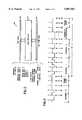
- FIG. 4is a timing diagram for the audio distribution packets used to transmit audio data throughout the life safety system of FIG. 1;
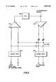
- FIG. 5is a schematic diagram of remote audio data interface of FIG. 3 for isolating and routing audio data
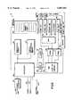
- FIG. 6is a block diagram of the audio source module or unit (“ASU") of FIG. 1;
- FIG. 7is a block diagram of the audio amplifier module of FIG. 1.
- a life safety systemincludes groups or local area networks (“LANs”) of intelligent devices in which each group monitors the safety conditions in a particular zone, such as an entire building or a portion thereof.
- the life safety systemincludes a plurality of central processing units (“CPUs”) that are linked in series by CPU-to-CPU communication lines.
- CPUscentral processing units
- Each CPUcontrols CPU-to-CPU communications and monitors the environment of a particular zone to determine whether conditions in the zone are safe. If the life safety system determines that the occupants in a particular zone should be warned about an actual or potential unsafe condition, the CPU would undertake the task of providing audio and/or visual warnings to the occupants of its zone.
- the audio communication system of the present inventionprovides the CPU with the ability to perform this task as well as any other task where audio communications may be desired.
- each CPUis networked to a variety of I/O hardware modules or local rail modules ("LRMs") by a plurality of local communication lines or local rails.
- LRMslocal rail modules
- the LRMsprovide the CPU with information relating to the safety conditions throughout the zone and assist the CPU in distributing warning signals and messages to the occupants in the zone.
- the CPUis always a master device on the local rails and, thus, may communicate with any LRM connected to the local rails.
- the life safety systemsupports CPU-to-CPU communication of command/control data, response data, and audio signals between CPUs of different zones.
- the systemis capable of providing CPU-to-Module communications of power, command/control data, response data, test data and audio signals between a CPU and one of its respective LRMs in a particular zone.
- the systemis capable of providing Module-to-Device communications of power, command/control data, response data, test data and audio signals for life safety devices, such as smoke detectors or audio speakers, that are coupled to a particular LRM.
- the audio communication system of the present inventionprovides the life safety system with the ability to control the processing of audio information at the CPUs, LRMs and devices and, also, the distribution of audio information via CPU-to-CPU communications, CPU-to-Module communications and Module-to-Device communications.
- the audio communication portion 10 of the panel arrangement 1comprises an audio source module or unit ("ASU") 12, an audio amplifier module 14, and one or more audio devices or speakers 16 connected to the audio amplifier module.
- ASUaudio source module or unit
- the audio communication portion 10includes the CPU 18 for full integration in the life safety system.
- audio data functionsthat are not already available in the CPU are added via an audio data interface and/or downloaded as software to a memory portion of the CPU, described below.
- the audio communication portion 10may have a plurality of ASUs 12, audio amplifier modules 14 and CPUs 18 for more concentrated coverage of the particular zone or for backup capabilities.
- the CPUs 18are linked together by general data lines 20 and audio data lines 22 for CPU-to-CPU communications.
- each CPU 18is connected for communication with a plurality of LRMs 24 by one or more local rails 26, 27, which includes a power line, auto-addressing line, audio data line, common alarm indication line, power supply control line, and general data line.
- the general data lineis used for command/control, response data, and test data.
- the local audio data line 28which is connected between the CPU 18 and the ASU 12 transfers audio data to the CPU, and the CPU places the audio data on one of the local rails 26, 27. Audio data that is received by the CPU 18 from the ASU 12 is routed through a particular audio circuit 67 (shown in FIG.
- the CPU 18also supervises the audio data received from the ASU 12 and buffers the audio data before placing it on the remote audio data line 22.
- the local audio data line 28may be combined with the general data line on the local rails 26, 27 to provide a single communication line so long as the primary functions of these lines, as described below, are not significantly changed.
- LRMs 24may be coupled to the local rails 26, 27.
- the varying types of LRMsinclude, but are not limited to, a loop controller module 32, power supply module 34, traditional zone module 36, reverse polarity module 38, ASU 12, audio amplifier module 14 and telephone module 42 as shown in FIG. 1.
- the loop controller module 32may be connected to a plurality of devices, such as a plurality of smoke detectors 44 and a transponder 46.
- the audio amplifier module 14may be connected to a plurality of audio devices or loud speakers 16.
- the local rails 26, 27 shown in FIG. 1are merely diagrammatic representations of the actual local rails of the preferred embodiment.
- the local rails in FIG. 1are the audio rail 26 and the other rail 27 whereas, for the preferred embodiment, there are actually two local rails each having a plurality of address and data lines (shown in FIG. 2).
- the audio portion of the local rails 26, 27has been distinctly separated from the other portions of the local rails to more clearly describe the present invention.
- the preferred local rails 26, 27comprises a top rail 48 and a bottom rail 50 in which each rail includes a plurality of communication or power lines.
- the specific types of signals that may be provided on the local rails 26, 27include, but are not limited to, general data lines, address lines, selection lines, audio data lines, voltage lines (such as 5 volts or 24 volts), common lines, common alarm, power supply sensing lines, power supply control and/or reference lines and earth ground lines.
- the local rails 26, 27provides communication between the CPU 18 and a particular LRM 24 and between two or more LRMs.
- an alarm signal corresponding to a particular local alarm conditionmay be transmitted by an LRM 24 via the local rails 26, 27 so that all other LRMs 24 connected to the local rails 26, 27 will be aware of the condition.
- the LRM 24will continue to activate the common alarm signal until CPU communications is resumed or the local alarm condition becomes safe.
- the preferred embodiment of the audio communication portion 10comprises a network of up to sixty-four CPUs 18 interconnected by communication lines 20, 22, preferably RS-485 data lines, with each CPU supporting up to nineteen hardware modules LRMs 24 that are responsible for the system input/output functions.
- the CPU 18is the local bus master and supervises all bus traffic. For example, the CPU 18 performs built in test functions upon power up and user request via a user interface. Also, the CPU 18 assigns all LRM addresses based on positional priority in which the LRMs 24 closer to the CPU 18 are given higher priority.
- each LRM 24Throughout the operation of the audio communication portion 10, possible local alarm conditions are monitored and processed by each LRM 24 on the local rails 26, 27 and appropriate actions in each zone are taken in response to certain conditions.
- Each LRM 24must have the capability to function properly in a local alarm condition even when CPU communications has been lost due to CPU, local rails or module problems. Generally during CPU communication loss, the LRM 24 operates independently and maintains the last state commanded by the CPU 18 and continues to queue alarm and exception deltas as necessary.
- Each CPU 18 that includes at least one ASU 12 on its local rails 26, 27will inform the ASU or ASUs to broadcast a particular audio signal on one of its eight audio channels.
- each CPU 18 that controls an audio amplifier module 14will inform the local amplifier module to receive input from a specific channel, send output to its speakers, and energize its visual circuit.
- the CPUincludes a processor 52 connected to a variety of CPU components for controlling CPU's major functions.
- the processor 52should have a minimum word length of 16 bits and the ability to address more that 16 megabytes of address and I/O space, such as the 68302 processor which is available from Motorola Inc. in Shaumburg, Ill.
- Operating system software, program software, rail and system wide data, and program dataare stored in random access memory (“RAM") 54 and nonvolatile memory 56.
- RAMrandom access memory
- Such informationmay be downloaded from another CPU 18 via a CPU interface 58 or from an external device, such as a personal computer, via a serial port 60.
- such informationmay be downloaded to the respective LRMs 24 connected to the local rails 26, 27 via a module interface 62.
- the CPU 18may also interact with a user by receiving instructions from the serial port 60 and sending information to a display via a display interface 64 and a printer via a printer port 66.
- the nonvolatile memory 56stores program and database information
- the RAM 54stores run-time data.
- the processor 52 of the CPU 18also controls a remote audio data interface 67, system reset interface 68, auto address master 70 and audio data interface 72.
- the remote audio data interface 67provides isolation and routing of audio data.
- the system reset interface 68implements a watch dog function for recovery from incorrect firmware performance. Thus, the system reset interface 68 drives and detects reset signals.
- the auto address master 70permits the processor 52 to determine the address of each LRM connected to the local rails.
- the audio data interface 72implements audio data functions, such as support for CPU-to-module communications. Also, where a dedicated audio data line 22 to another CPU and/or a dedicated local audio data line 28 to the LRM 24 is available, such as the preferred embodiment shown in FIG. 1, processor 52 will transmit and receive audio information on such data lines via the audio data interface 72.
- the audio data interface 72is a daughter board that may be easily installed in the CPU 18.
- each frame 74includes eight channels 76 of digital audio data delimited by a frame sync 78, and each channel uses a differential Manchester.
- the frame sync 78is defined by the absence of 2 clock cycles.
- each frame 74comprises thirty-four bits in which each of the eight channels is 4 bits and the frame sync 78 is 2 bits.
- the frame syncoccurs at a 9600 Hz. rate.
- a "0" (zero)is defined by a transition occurring in the middle of 2 clock cycles and a "1" (one) is defined by the absence of a transition in the middle of 2 clock cycles.
- a new packet or frame 74is transmitted or received every 104.17 ⁇ sec., i.e. 9600 Hz. This results in a data rate of about 326,400 bps.
- Data bits of the preferred embodimentare transmitted as pulses with a width of about 1.53 ⁇ sec. for a logic 0 and 3.06 ⁇ sec. for a logic 1.
- the remote audio data interface 67(shown in FIG. 3) of the CPU 18 provides isolation and routing of audio data.
- the data interface 67comprises a receiving transient protection 120, a driving transient protection 122, a differential receiver 124, a differential driver 126 and an electrical isolator ("Opto") 128.
- relay switchesnamely differential receiver 124 and differential driver 126, determine if there is a panel failure. If so, the incoming signal received by receiving transient protection 120 is passed to the next panel through the driving transient protection 122.
- the receiving and driving transient protection 120, 122protect the circuitry from transients, such as lightning, static and the like.
- the electrical isolatorhelps the panel function when a ground fault is present and also helps the system determine where the ground fault is located by isolating the ground fault to an area.
- the ASU 12interfaces to the local rails and can generate eight different audio tones and/or messages simultaneously.
- the ASU 12has the ability to multiplex eight audio output channels onto a single output interface to audio amplifier modules 14.
- the local communication lines for the ASU 12, either the local rails 26, 27 or the local audio data line 28,have the capability of transmitting eight channels of audio data.
- these eight channelsinclude a general channel, page channel, alert channel, evacuation channel and auxiliary channel.
- Each of the eight audio data channelsoriginate from pre-recorded messages, real-time digital signal processor ("DSP") inputs, or non-active data patterns.
- DSPreal-time digital signal processor
- a local microphone port 80, remote microphone port 82, telephone port 84 and auxiliary audio device port 86are supported by an on-board DSP 90 for real-time input.
- a page out port 85provides a select page input as an output.
- the ASU 12includes a processor 88, preferably a 68302 microprocessing unit described above for the CPU 18, that receives execution program code from the CPU at bootup.
- a processor-to-ASU communication driver, a small download receive module, and an audio message databaseare permanently resident in a nonvolatile memory portion 92 of the ASU 12 while powered down.
- processor configuration datais received from the CPU 18.
- Audio tones and messagesare received from the CPU 18 via the local rails 26, 27 or, if available, the local audio data line 28 shown in FIG. 1.
- the audio tones or messagesmay be received from the local audio data line 28 through an audio interface 87 or directly from the local rails 26, 27.
- such tones and messagesmay be generated locally at or near the ASU 12 and distributed to the CPU 18 and other LRMs 24 via the local rails 26, 27 or the local audio data line 28.
- the CPUs 18also have the capability of transmitting audio data to each other via audio data lines 22. Therefore, no matter where the tones or messages may originate, the audio communication portion 10 of the present invention is capable of distributing them to any and all ASUs 12 in the life safety system.
- the ASU 12generates eight multiplexed digital audio tones from either prerecorded messages which are stored in nonvolatile memory 92 or from live audio signal from a local microphone 130, a remote microphone 132, a local telephone, or an auxiliary input.
- the operation of these devicesmay be monitored by a panel of displays and switches 136.
- the local microphone 130 and the remote microphone 132are also coupled to a buffer 134 which leads directly to the processor 88.
- Prerecorded messagesreside in either on-board nonvolatile memory 92 or on a plug-in nonvolatile memory PCMCIA card 94.
- default messages contained in on-board nonvolatile memory 92are downloaded to the ASU 12 when the ASU is manufactured.
- custom messagesare downloaded via an external port 138 from a computer system, usually in the field where the panel arrangement 1 is installed, and additional message capacity may be added by plugging in memory 94 of the PCMCIA card into the ASU 12.
- the default messagesmay be supplied in the PCMCIA nonvolatile memory 94 when manufactured or custom messages may be downloaded from a computer system that includes a standard sound card installed therein.
- recorded messagesare compressed using ADPCM compression, formatted for download to the ASU 12.
- the ASU 12takes the recorded messages from either a dedicated external download or from the local rails 26, 27. To download from the local rails 26, 27, the computer system is plugged into the upload/download port on the computer system, the CPU 18 receives the data and places it on the local rails so that the ASU 12 can receive it from the local rails.
- the ASUhas a local microphone 130 with a push-to-talk ("PTT") switch and three external analog inputs, namely the remote microphone port 82, the telephone port 84 and the auxiliary audio device port 86.
- PTTpush-to-talk
- the messages recorded on the computer systemare downloaded to the ASU 12, which is less expensive than providing a computer with each ASU.
- the computer systemsare used as recording studios.
- pre-recorded tones and messagesare stored in non-volatile memory 92 of the ASU 12.
- audio tones and messagesmay be downloaded from the CPU 18 to the non-volatile memory 92.
- downloaded tones and messageswill overlay any factory supplied audio tones or messages.
- the present inventionmay utilize a wide variety of different computer systems to download data to the processor and memory portion of the CPU 18, ASU 12 and audio amplifier 14 of the present invention.
- one type of computer systemis set forth in co-pending U.S. patent application Ser. No. 08/644,478, filed on May 10, 1996 titled Configuration Programming System for a Life Safety Network, which application is owned by the assignee of the present invention. This co-pending application is incorporated herein by reference.
- PCMCIA memory 94may be interfaced to the ASU 12 to provide further storage for tones and messages and/or to transfer audio tones and messages to the ASU's processor 88. Such PCMCIA memory 94 may or may not require an actual download process.
- PCMCIA Message DatabaseUpon being plugged in, the PCMCIA Message Database will be mapped to a specific memory region by the processor 88. Any PCMCIA memory 94 plugged-in would disable usage of any factory supplied tones and messages supplied with the ASU 12.
- the recorded messagesmay be directly written to the PCMCIA card by the recording station (computer) after, which, the PCMCIA card may be plugged into the ASU. If the recording station does not have a PCMCIA interface, then the messages will have to be downloaded to the ASU from the recording station and the ASU will write the messages to the PCMCIA card.
- the processor 88communicates to the DSP 90 via two 8-bit latches 96, 97 which control the timing for beginning and ending the transfer of audio data.
- the processor 88sets up a buffered DMA function to provide ADPCM audio data transfer from the DSP 90 to the internal buffer memory of the processor 88.
- the DMA transfer through the latches 96, 97contains two ADPCM audio data samples from a single channel.
- the processor 88also directly controls which user audio input device, excluding the auxiliary audio device port 86, is connected to one of the CODECs 98, 100.
- the DSP 90performs ADPCM compressions real time which is then passed to the processor 88 via a parallel interface.
- the DSP 90communicates to the processor 88 using an 8-bit protocol.
- the DSP 90is an analog device 2115 running at 14.7456 MHz. If at some point the processor 88 fails, then the DSP 90 will be allowed to process data and shall continue to do read the data from the CODECs 98, 100.
- audio datamay be provided to the ASU 12 via the local microphone port 80, remote microphone port 82, telephone port 84 and auxiliary device port 86. Since the local microphone port 80, remote microphone port 82, and telephone port 84 lead to a single CODEC 98, a multiplexor or MUX 102 is used to select one, and only one, of the three as a paging input to the CODEC. Both CODECs 98, 100 are configured to compand data using u-Law encoding. One CODEC 98 is connected to a paging channel and the other CODEC 100 is connected to an auxiliary channel. The word size from each CODEC 98, 100 is 8 bits.
- the CODECs 98, 100code a 14-bit linear sample to an 8-bit companded value.
- the 8-bit companded valueis then be inputted to the ADPCM algorithm of the DSP 90 to yield a two 4-bit ADPCM values for subsequent transmission to the processor 88.
- the ASUwill switch the local mic. input into the CODEC via the mux.
- the CODECwill convert the analog information to a companded 8-bit value.
- the DSPwill take the 8-bit companded value and convert it to a 4-bit ADPCM value.
- the ADPCM valueis then passed to the processor so that it may multiplex the "live" mic. signal in with the other prerecorded message channels and the other "live” channel, i.e., the Aux. input which is also compressed and given to the processor (main CPU). Note that only one of the three paging inputs can be converted at any given time, i.e. paging can occur form either the local mic., remote mic.
- each CPU 18 that controls an ASU 12will inform the ASU to put a particular audio signal on one of the eight audio channels.
- each CPU 18 that controls an audio amplifier module 14informs the audio amplifier module to receive input from a specific channel, send output to its audio devices or speakers 16, and energize its visual circuit.
- the audio amplifier module 14is able to select one of eight digitized audio input channels for routing eventually to a group of audio devices or loud speakers 16.
- the audio amplifier module 14connects to the local rails 26, 27 such that the CPU 18 controls the inputs and outputs of the audio amplifier module.
- the output circuit of the audio amplifier module 14supervises the field wiring integrity to the audio devices or speakers 16. If there is a break to the end of line resistor, then the audio amplifier module 14 will inform the CPU 18 of a problem or fault.
- the audio amplifier module 14also supervises the connection of the audio data signal. In particular, the audio amplifier module 14 will digitally create a universal evacuation tone if the audio data signal fails.
- Each audio amplifier module 14also has one output circuit to drive visual signals (strobe lights) for the hearing impaired.
- Each audio amplifier module 14receives a digital audio signal, selects an audio program, decompresses to signal and converts its back to an analog signal.
- the audio amplifier module 14includes a processor 104, decoder 106, digital signal processor ("DSP") 108, CODEC 110 and switching amp 112.
- DSPdigital signal processor
- audio data signals from the ASU 12may be received via the local rails 26, 27 or the local audio data line 28.
- control signals from the CPU 18, including the channel addressare received by the audio amplifier module's processor 104 via the local rails 26, 27.
- the decoder 106such as a PAL, shall decode the audio data signals received on the particular channel specified by the control signals to produce 4-bit ADPCM data for one channel.
- the DSP 108then processes the 4-bit ADPCM data to produce an 8-bit companded data for one channel.
- the CODEC 110processes the 8-bit companded data to produce an analog signal corresponding to a particular audio tone or message.
- the analog signalis amplified by the switching amp 112 which sends its output to one or speakers 16 for broadcasting the tone or message.
- the switching amp 112has four optional audio power output ratings, 15 watts, 30 watts, 45 watts and 60 watts which are specified by the processor 104.
- the audio amplifier module 14has the ability to attenuate input signals by 1/2 under software control to allow background audio to be output at 50% power output.
- the audio amplifier module 14When no output is selected, the audio amplifier module 14 has the capability of monitoring the audio zone for AC and DC short and/or open circuit conditions for class A or B connection. The audio amplifier module 14 will monitor it's own performance and has the ability to switch a backup audio signal to the audio devices or loud speakers 16 in the event of a problem or component failure.
Landscapes
- Physics & Mathematics (AREA)
- General Physics & Mathematics (AREA)
- Electromagnetism (AREA)
- Alarm Systems (AREA)
Abstract
Description
Claims (18)
Priority Applications (3)
| Application Number | Priority Date | Filing Date | Title |
|---|---|---|---|
| US08/644,834US5887067A (en) | 1996-05-10 | 1996-05-10 | Audio communication system for a life safety network |
| DE69711114TDE69711114T2 (en) | 1996-05-10 | 1997-05-09 | System for the transmission of audio signals in an emergency evacuation network |
| EP97303157AEP0806750B1 (en) | 1996-05-10 | 1997-05-09 | Audio communication system for a life safety network |
Applications Claiming Priority (1)
| Application Number | Priority Date | Filing Date | Title |
|---|---|---|---|
| US08/644,834US5887067A (en) | 1996-05-10 | 1996-05-10 | Audio communication system for a life safety network |
Publications (1)
| Publication Number | Publication Date |
|---|---|
| US5887067Atrue US5887067A (en) | 1999-03-23 |
Family
ID=24586526
Family Applications (1)
| Application Number | Title | Priority Date | Filing Date |
|---|---|---|---|
| US08/644,834Expired - LifetimeUS5887067A (en) | 1996-05-10 | 1996-05-10 | Audio communication system for a life safety network |
Country Status (3)
| Country | Link |
|---|---|
| US (1) | US5887067A (en) |
| EP (1) | EP0806750B1 (en) |
| DE (1) | DE69711114T2 (en) |
Cited By (20)
| Publication number | Priority date | Publication date | Assignee | Title |
|---|---|---|---|---|
| JPH11259960A (en)* | 1997-09-24 | 1999-09-24 | Sony Pictures Entertainment | Track control method and controller |
| US20010047440A1 (en)* | 2000-04-04 | 2001-11-29 | Yoshiyuki Takaku | Information processing device, control device, information processing system, and methods thereof |
| US6449662B1 (en) | 1997-01-13 | 2002-09-10 | Micro Ear Technology, Inc. | System for programming hearing aids |
| US20020168075A1 (en)* | 1997-01-13 | 2002-11-14 | Micro Ear Technology, Inc. | Portable system programming hearing aids |
| US20030063755A1 (en)* | 2001-09-28 | 2003-04-03 | Nourse James D. | System for controlling remote speakers using centralized amplifiers, centralized monitoring and master/slave communication protocol |
| US20030169177A1 (en)* | 2001-12-19 | 2003-09-11 | Wheelock, Inc | Method and apparatus for boosting an audible signal in a notification system |
| US6732235B1 (en)* | 1999-11-05 | 2004-05-04 | Analog Devices, Inc. | Cache memory system and method for a digital signal processor |
| US20040131199A1 (en)* | 2001-02-26 | 2004-07-08 | 777388 Ontario Limited | Networked sound masking and paging system |
| US20040204921A1 (en)* | 1998-01-09 | 2004-10-14 | Micro Ear Technology, Inc., D/B/A Micro-Tech. | Portable hearing-related analysis system |
| US20040243750A1 (en)* | 2003-05-30 | 2004-12-02 | Stubbs Timothy Christopher | Security or safety bus system |
| US20050008175A1 (en)* | 1997-01-13 | 2005-01-13 | Hagen Lawrence T. | Portable system for programming hearing aids |
| US20050201541A1 (en)* | 2004-03-12 | 2005-09-15 | Berezowski Andrew G. | Internet facilitated emergency and general paging system |
| US20050283263A1 (en)* | 2000-01-20 | 2005-12-22 | Starkey Laboratories, Inc. | Hearing aid systems |
| US20060140391A1 (en)* | 2004-12-01 | 2006-06-29 | Brian Bizjak | Supervised paging, messaging background music and emergency voice evacuation system |
| US20080075307A1 (en)* | 2006-01-30 | 2008-03-27 | Penton Audio Usa | Digital Signal Processing Amplifier |
| US20090306798A1 (en)* | 2008-06-06 | 2009-12-10 | Niklas Moeller | System and method for monitoring/controlling a sound masking system from an electronic floorplan |
| USRE41871E1 (en)* | 1998-03-25 | 2010-10-26 | Adt Services Ag | Alarm system with individual alarm indicator testing |
| US8300862B2 (en) | 2006-09-18 | 2012-10-30 | Starkey Kaboratories, Inc | Wireless interface for programming hearing assistance devices |
| US20180124542A1 (en)* | 2015-04-13 | 2018-05-03 | Robert Bosch Gmbh | Audio system, calibration module, operating method, and computer program |
| US9990838B1 (en)* | 2017-02-23 | 2018-06-05 | Yi-Lun Yang | Digital emergency signal transfer system |
Families Citing this family (3)
| Publication number | Priority date | Publication date | Assignee | Title |
|---|---|---|---|---|
| GB9820644D0 (en)* | 1998-09-22 | 1998-11-18 | Vimpex Limited | Public address apparatus |
| GB0122395D0 (en)* | 2001-09-17 | 2001-11-07 | Fulleon Ltd | Alarm system |
| CH696048A5 (en)* | 2002-07-19 | 2006-11-30 | Barix Ag | Warning system. |
Citations (6)
| Publication number | Priority date | Publication date | Assignee | Title |
|---|---|---|---|---|
| US3964047A (en)* | 1974-06-19 | 1976-06-15 | Wheelock Signals, Inc. | Fire-alarm audible signaling system permitting selective communications and signaling |
| US5034808A (en)* | 1989-05-30 | 1991-07-23 | Murray Harold R | Unified automatic video and audio signal control and distribution system |
| US5345510A (en)* | 1992-07-13 | 1994-09-06 | Rauland-Borg Corporation | Integrated speaker supervision and alarm system |
| US5363434A (en)* | 1991-01-09 | 1994-11-08 | Square D Company | Audio distribution system |
| US5548281A (en)* | 1993-07-16 | 1996-08-20 | Brother Kogyo Kabushiki Kaisha | Data transmission system |
| US5596647A (en)* | 1993-06-01 | 1997-01-21 | Matsushita Avionics Development Corporation | Integrated video and audio signal distribution system and method for use on commercial aircraft and other vehicles |
Family Cites Families (3)
| Publication number | Priority date | Publication date | Assignee | Title |
|---|---|---|---|---|
| GB2084783B (en)* | 1980-10-02 | 1985-06-19 | Production Eng Res | Audio system |
| AU8140182A (en)* | 1981-02-18 | 1982-09-14 | Blue Circle Industries Plc | Electronic warning system |
| GB8827787D0 (en)* | 1988-11-28 | 1988-12-29 | Millbank Electronics Group Ltd | Safety system |
- 1996
- 1996-05-10USUS08/644,834patent/US5887067A/ennot_activeExpired - Lifetime
- 1997
- 1997-05-09EPEP97303157Apatent/EP0806750B1/ennot_activeExpired - Lifetime
- 1997-05-09DEDE69711114Tpatent/DE69711114T2/ennot_activeExpired - Fee Related
Patent Citations (6)
| Publication number | Priority date | Publication date | Assignee | Title |
|---|---|---|---|---|
| US3964047A (en)* | 1974-06-19 | 1976-06-15 | Wheelock Signals, Inc. | Fire-alarm audible signaling system permitting selective communications and signaling |
| US5034808A (en)* | 1989-05-30 | 1991-07-23 | Murray Harold R | Unified automatic video and audio signal control and distribution system |
| US5363434A (en)* | 1991-01-09 | 1994-11-08 | Square D Company | Audio distribution system |
| US5345510A (en)* | 1992-07-13 | 1994-09-06 | Rauland-Borg Corporation | Integrated speaker supervision and alarm system |
| US5596647A (en)* | 1993-06-01 | 1997-01-21 | Matsushita Avionics Development Corporation | Integrated video and audio signal distribution system and method for use on commercial aircraft and other vehicles |
| US5548281A (en)* | 1993-07-16 | 1996-08-20 | Brother Kogyo Kabushiki Kaisha | Data transmission system |
Cited By (56)
| Publication number | Priority date | Publication date | Assignee | Title |
|---|---|---|---|---|
| US20100086153A1 (en)* | 1997-01-13 | 2010-04-08 | Micro Ear Technology, Inc. D/B/A Micro-Tech | Portable system for programming hearing aids |
| US7451256B2 (en) | 1997-01-13 | 2008-11-11 | Micro Ear Technology, Inc. | Portable system for programming hearing aids |
| US6449662B1 (en) | 1997-01-13 | 2002-09-10 | Micro Ear Technology, Inc. | System for programming hearing aids |
| US20020168075A1 (en)* | 1997-01-13 | 2002-11-14 | Micro Ear Technology, Inc. | Portable system programming hearing aids |
| US7054957B2 (en)* | 1997-01-13 | 2006-05-30 | Micro Ear Technology, Inc. | System for programming hearing aids |
| US20050196002A1 (en)* | 1997-01-13 | 2005-09-08 | Micro Ear Technology, Inc., D/B/A Micro-Tech | Portable system for programming hearing aids |
| US6888948B2 (en) | 1997-01-13 | 2005-05-03 | Micro Ear Technology, Inc. | Portable system programming hearing aids |
| US7929723B2 (en) | 1997-01-13 | 2011-04-19 | Micro Ear Technology, Inc. | Portable system for programming hearing aids |
| US7787647B2 (en) | 1997-01-13 | 2010-08-31 | Micro Ear Technology, Inc. | Portable system for programming hearing aids |
| US20050008175A1 (en)* | 1997-01-13 | 2005-01-13 | Hagen Lawrence T. | Portable system for programming hearing aids |
| US6851048B2 (en) | 1997-01-13 | 2005-02-01 | Micro Ear Technology, Inc. | System for programming hearing aids |
| US7167763B2 (en)* | 1997-09-24 | 2007-01-23 | Sony Corporation | Method and apparatus for providing a graphical user interface for a player/recorder system |
| JPH11259960A (en)* | 1997-09-24 | 1999-09-24 | Sony Pictures Entertainment | Track control method and controller |
| US6895345B2 (en) | 1998-01-09 | 2005-05-17 | Micro Ear Technology, Inc. | Portable hearing-related analysis system |
| US20040204921A1 (en)* | 1998-01-09 | 2004-10-14 | Micro Ear Technology, Inc., D/B/A Micro-Tech. | Portable hearing-related analysis system |
| USRE41871E1 (en)* | 1998-03-25 | 2010-10-26 | Adt Services Ag | Alarm system with individual alarm indicator testing |
| US6732235B1 (en)* | 1999-11-05 | 2004-05-04 | Analog Devices, Inc. | Cache memory system and method for a digital signal processor |
| US9357317B2 (en) | 2000-01-20 | 2016-05-31 | Starkey Laboratories, Inc. | Hearing aid systems |
| US20050283263A1 (en)* | 2000-01-20 | 2005-12-22 | Starkey Laboratories, Inc. | Hearing aid systems |
| US8503703B2 (en) | 2000-01-20 | 2013-08-06 | Starkey Laboratories, Inc. | Hearing aid systems |
| US9344817B2 (en) | 2000-01-20 | 2016-05-17 | Starkey Laboratories, Inc. | Hearing aid systems |
| US7072991B2 (en) | 2000-04-04 | 2006-07-04 | Sony Corporation | Audio visual system having a serial bus for identifying devices connected to the external terminals of an amplifier in the system |
| US20050188134A1 (en)* | 2000-04-04 | 2005-08-25 | Yoshiyuki Takaku | Audio visual system having a serial bus for identifying devices connected to the external terminals of an amplifier in the system |
| US6910085B2 (en)* | 2000-04-04 | 2005-06-21 | Sony Corporation | Audio visual system having a serial bus for identifying devices connected to the external terminals of an amplifier in the system |
| US7072993B2 (en) | 2000-04-04 | 2006-07-04 | Sony Corporation | Audio visual system having a serial bus for identifying devices connected to the external terminals of an amplifier in the system |
| US7072992B2 (en) | 2000-04-04 | 2006-07-04 | Sony Corporation | Audio visual system having a serial bus for identifying devices connected to the external terminals of an amplifier in the system |
| US7072990B2 (en) | 2000-04-04 | 2006-07-04 | Sony Corporation | Audio visual system having a serial bus for identifying devices connected to the external terminals of an amplifier in the system |
| US20050188133A1 (en)* | 2000-04-04 | 2005-08-25 | Yoshiyuki Takaku | Audio visual system having a serial bus for identifying devices connected to the external terminals of an amplifier in the system |
| US20050172042A1 (en)* | 2000-04-04 | 2005-08-04 | Yoshiyuki Takaku | Audio visual system having a serial bus for identifying devices connected to the external terminals of an amplifier in the system |
| US20050188132A1 (en)* | 2000-04-04 | 2005-08-25 | Yoshiyuki Takaku | Audio visual system having a serial bus for identifying devices connected to the external terminals of an amplifier in the system |
| US20010047440A1 (en)* | 2000-04-04 | 2001-11-29 | Yoshiyuki Takaku | Information processing device, control device, information processing system, and methods thereof |
| US8817999B2 (en)* | 2001-02-26 | 2014-08-26 | 777388 Ontario Limited | Networked sound masking and paging system |
| US20040131199A1 (en)* | 2001-02-26 | 2004-07-08 | 777388 Ontario Limited | Networked sound masking and paging system |
| US10121463B2 (en) | 2001-02-26 | 2018-11-06 | 777388 Ontario Limited | Networked sound masking system |
| US20030063755A1 (en)* | 2001-09-28 | 2003-04-03 | Nourse James D. | System for controlling remote speakers using centralized amplifiers, centralized monitoring and master/slave communication protocol |
| US7197148B2 (en) | 2001-09-28 | 2007-03-27 | Hubbell Incorporated | System for controlling remote speakers using centralized amplifiers, centralized monitoring and master/slave communication protocol |
| US20030169177A1 (en)* | 2001-12-19 | 2003-09-11 | Wheelock, Inc | Method and apparatus for boosting an audible signal in a notification system |
| US8457330B2 (en) | 2001-12-19 | 2013-06-04 | Wheelock, Inc. | Method and apparatus for boosting an audible signal in a notification system |
| US20090153339A1 (en)* | 2001-12-19 | 2009-06-18 | Curran John W | Method and apparatus for boosting an audible signal in a notification system |
| US7428311B2 (en)* | 2001-12-19 | 2008-09-23 | Wheelock, Inc. | Method and apparatus for boosting an audible signal in a notification system |
| US20090025956A1 (en)* | 2003-05-30 | 2009-01-29 | Timothy Christopher Stubbs | Security or Safety Bus System |
| US20040243750A1 (en)* | 2003-05-30 | 2004-12-02 | Stubbs Timothy Christopher | Security or safety bus system |
| US20070110221A1 (en)* | 2004-03-12 | 2007-05-17 | Berezowski Andrew G | Internet Facilitated Emergency and General Paging System |
| US7961848B2 (en) | 2004-03-12 | 2011-06-14 | Honeywell International Inc. | Internet facilitated emergency and general paging system |
| US20050201541A1 (en)* | 2004-03-12 | 2005-09-15 | Berezowski Andrew G. | Internet facilitated emergency and general paging system |
| US7218708B2 (en)* | 2004-03-12 | 2007-05-15 | Honeywell International, Inc. | Internet facilitated emergency and general paging system |
| US8107595B2 (en)* | 2004-12-01 | 2012-01-31 | Wheelock, Inc. | Supervised paging, messaging background music and emergency voice evacuation system |
| US20060140391A1 (en)* | 2004-12-01 | 2006-06-29 | Brian Bizjak | Supervised paging, messaging background music and emergency voice evacuation system |
| US20080075307A1 (en)* | 2006-01-30 | 2008-03-27 | Penton Audio Usa | Digital Signal Processing Amplifier |
| US8300862B2 (en) | 2006-09-18 | 2012-10-30 | Starkey Kaboratories, Inc | Wireless interface for programming hearing assistance devices |
| US8666086B2 (en) | 2008-06-06 | 2014-03-04 | 777388 Ontario Limited | System and method for monitoring/controlling a sound masking system from an electronic floorplan |
| US9916124B2 (en) | 2008-06-06 | 2018-03-13 | 777388 Ontario Limited | System and method for controlling and monitoring a sound masking system from an electronic floorplan |
| US20090306798A1 (en)* | 2008-06-06 | 2009-12-10 | Niklas Moeller | System and method for monitoring/controlling a sound masking system from an electronic floorplan |
| US20180124542A1 (en)* | 2015-04-13 | 2018-05-03 | Robert Bosch Gmbh | Audio system, calibration module, operating method, and computer program |
| US10225678B2 (en)* | 2015-04-13 | 2019-03-05 | Robert Bosch Gmbh | Audio system, calibration module, operating method, and computer program |
| US9990838B1 (en)* | 2017-02-23 | 2018-06-05 | Yi-Lun Yang | Digital emergency signal transfer system |
Also Published As
| Publication number | Publication date |
|---|---|
| EP0806750A1 (en) | 1997-11-12 |
| DE69711114T2 (en) | 2002-10-24 |
| DE69711114D1 (en) | 2002-04-25 |
| EP0806750B1 (en) | 2002-03-20 |
Similar Documents
| Publication | Publication Date | Title |
|---|---|---|
| US5887067A (en) | Audio communication system for a life safety network | |
| US20120201326A1 (en) | Signal and devices for wired networks | |
| US8428153B2 (en) | Signal and devices for wired networks | |
| US20070035407A1 (en) | Alarm system with speaker | |
| US20040220687A1 (en) | Device and method for transmitting, receiving and processing audio control signals in information systems | |
| KR20210040525A (en) | Public address system enable to control speaker system using smartphone | |
| EP1451787B1 (en) | A fire alarm module | |
| KR100417495B1 (en) | Broadcasting system using matrix type connection structure amp and speaker | |
| KR100374154B1 (en) | System for receiving and transmitting power signal and data signal | |
| AU2002319484A1 (en) | A fire alarm module | |
| US20020135491A1 (en) | Electronically controlled multi-tone peripheral | |
| JPH11161881A (en) | Alarm monitoring system for multiple dwelling house | |
| JP3479135B2 (en) | Disaster prevention monitoring device | |
| US8411875B2 (en) | Speaker control via audio connection | |
| JP2902254B2 (en) | Disaster prevention monitoring device | |
| JP2891045B2 (en) | Broadcast-type conference image transmission device | |
| KR100879754B1 (en) | Public Speaker System Using Identifier | |
| US8217798B2 (en) | System, converter and method for wide area distribution of supervised emergency audio | |
| US5822417A (en) | Phone control center for a life safety network | |
| JP2001126161A (en) | Automatic fire alarm system | |
| KR100550838B1 (en) | Integrated Broadcasting System | |
| JP3667463B2 (en) | Fire alarm system for apartment houses | |
| WO2003025874A1 (en) | Alarm system | |
| JPH10302183A (en) | Disaster prevention alarm monitor integrated board for apartment house and disaster prevention monitor system for apartment house using this board | |
| JPS62254298A (en) | Sensor input monitoring system |
Legal Events
| Date | Code | Title | Description |
|---|---|---|---|
| AS | Assignment | Owner name:GENERAL SIGNAL CORPORATION, CONNECTICUT Free format text:ASSIGNMENT OF ASSIGNORS INTEREST;ASSIGNORS:COSTA, HILARIO S.;MEYER-HORTON, ELIZABETH;MUNN, DONALD J.;AND OTHERS;REEL/FRAME:007972/0161;SIGNING DATES FROM 19960503 TO 19960506 | |
| STCF | Information on status: patent grant | Free format text:PATENTED CASE | |
| AS | Assignment | Owner name:SAC CORP. (DE CORP.), MICHIGAN Free format text:MERGER;ASSIGNOR:GENERAL SIGNAL CORPORATION (NY CORP);REEL/FRAME:010937/0232 Effective date:19981006 | |
| AS | Assignment | Owner name:GENERAL SIGNAL CORPORATION (DE CORP.), MICHIGAN Free format text:CHANGE OF NAME;ASSIGNOR:SAC CORP. (DE CORP.);REEL/FRAME:010927/0929 Effective date:19981006 | |
| AS | Assignment | Owner name:CHASE MANHATTAN BANK, AS COLLATERAL AGENT, THE, NE Free format text:CONDITIONAL ASSIGNMENT OF AND SECURITY INTEREST IN PATENT RIGHTS;ASSIGNOR:GSBS DEVELOPMENT CORPORATION (DE CORPORATION);REEL/FRAME:011035/0185 Effective date:20000613 | |
| AS | Assignment | Owner name:EDWARDS SYSTEMS TECHNOLOGY, INC., MICHIGAN Free format text:ASSIGNMENT OF ASSIGNORS INTEREST;ASSIGNOR:GENERAL SIGNAL CORPROATION;REEL/FRAME:011122/0841 Effective date:20000101 Owner name:GSBS DEVELOPMENT CORPORATION (DE CORP.), MICHIGAN Free format text:ASSIGNMENT OF ASSIGNORS INTEREST;ASSIGNOR:EDWARDS SYSTEMS TECHNOLOGY, INC. (CT CORP.);REEL/FRAME:011122/0939 Effective date:20000101 | |
| FPAY | Fee payment | Year of fee payment:4 | |
| REMI | Maintenance fee reminder mailed | ||
| AS | Assignment | Owner name:GSBS DEVELOPMENT CORPORATION, NORTH CAROLINA Free format text:TERMINATION AND RELEASE OF SECURITY INTEREST IN PATENT RIGHTS (PREVIOUSLY RECORDED AT REEL 11035 FRAME 0185);ASSIGNOR:JPMORGAN CHASE BANK, N.A., AS COLLATERAL AGENT;REEL/FRAME:016844/0286 Effective date:20051118 | |
| FPAY | Fee payment | Year of fee payment:8 | |
| AS | Assignment | Owner name:GE SECURITY, INC., FLORIDA Free format text:ASSIGNMENT OF ASSIGNORS INTEREST;ASSIGNOR:GSBS DEVELOPMENT CORPORATION;REEL/FRAME:017379/0262 Effective date:20050323 | |
| FPAY | Fee payment | Year of fee payment:12 |