US5886825A - Magnifier Lens - Google Patents
Magnifier LensDownload PDFInfo
- Publication number
- US5886825A US5886825AUS08/964,488US96448897AUS5886825AUS 5886825 AUS5886825 AUS 5886825AUS 96448897 AUS96448897 AUS 96448897AUS 5886825 AUS5886825 AUS 5886825A
- Authority
- US
- United States
- Prior art keywords
- lens element
- sub
- lens
- magnifier
- negative power
- Prior art date
- Legal status (The legal status is an assumption and is not a legal conclusion. Google has not performed a legal analysis and makes no representation as to the accuracy of the status listed.)
- Expired - Lifetime
Links
Images


Classifications
- G—PHYSICS
- G02—OPTICS
- G02B—OPTICAL ELEMENTS, SYSTEMS OR APPARATUS
- G02B27/00—Optical systems or apparatus not provided for by any of the groups G02B1/00 - G02B26/00, G02B30/00
- G02B27/0025—Optical systems or apparatus not provided for by any of the groups G02B1/00 - G02B26/00, G02B30/00 for optical correction, e.g. distorsion, aberration
- G02B27/005—Optical systems or apparatus not provided for by any of the groups G02B1/00 - G02B26/00, G02B30/00 for optical correction, e.g. distorsion, aberration for correction of secondary colour or higher-order chromatic aberrations
- G02B27/0056—Optical systems or apparatus not provided for by any of the groups G02B1/00 - G02B26/00, G02B30/00 for optical correction, e.g. distorsion, aberration for correction of secondary colour or higher-order chromatic aberrations by using a diffractive optical element
- G—PHYSICS
- G02—OPTICS
- G02B—OPTICAL ELEMENTS, SYSTEMS OR APPARATUS
- G02B25/00—Eyepieces; Magnifying glasses
- G02B25/001—Eyepieces
- G—PHYSICS
- G02—OPTICS
- G02B—OPTICAL ELEMENTS, SYSTEMS OR APPARATUS
- G02B25/00—Eyepieces; Magnifying glasses
- G02B25/002—Magnifying glasses
- G02B25/007—Magnifying glasses comprising other optical elements than lenses
- G—PHYSICS
- G02—OPTICS
- G02B—OPTICAL ELEMENTS, SYSTEMS OR APPARATUS
- G02B27/00—Optical systems or apparatus not provided for by any of the groups G02B1/00 - G02B26/00, G02B30/00
- G02B27/0025—Optical systems or apparatus not provided for by any of the groups G02B1/00 - G02B26/00, G02B30/00 for optical correction, e.g. distorsion, aberration
- G02B27/0037—Optical systems or apparatus not provided for by any of the groups G02B1/00 - G02B26/00, G02B30/00 for optical correction, e.g. distorsion, aberration with diffracting elements
Definitions
- This inventionrelates to high power magnifier lenses and more specifically to magnifier lenses suitable for use in display systems such as liquid crystal (LCD), or light emitting diode (LED) display systems.
- LCDliquid crystal
- LEDlight emitting diode
- focal lengthis inversely related to magnification and field of view.
- having a large field of viewmakes it difficult to correct off axis aberrations such as coma, astigmatism, lateral color, and defocus due to field curvature. These aberrations greatly reduce the image quality of the displayed image.
- a magnifier lens for a display systemis produced by the Kopin Corporation of Taunton, Mass. This magnifier lens is described in the Specification manual titled “Cyber DisplayTM 320 Monochrome Display Specifications", pages 3-19 through 3-20.
- This magnifier lenshas two lens elements, one with a diffractive surface, and provides a half field of view of only +/-8 degrees and a focal length of 21.4 mm.
- Some of the standard eyepiece lensesare suitable for use as magnifier lenses in display systems. These eyepiece lenses provide greater magnifications and larger fields of view than the above described magnifier lens, but suffer from off axis aberrations, particularly lateral color and field curvature. Such aberrations reduce the image quality at the edge of the displayed image.
- These eyepiece lensesare described on pages 14-4 through 14-19 of the "Military Standardization Handbook, Optical Design", Handbook number 141, published Oct. 5, 1962. More specifically, when these eyepiece lenses are scaled to a focal length of 16 mm, the lateral color aberration (of all but one of these lenses) at a field of view of +/-12 degrees is greater than 16 microns. This results in color fringing, decreased resolution and degraded image quality.
- the one eyepiece that does not have much lateral coloris described on pages 14-8 through 14-9.
- This eyepiecesuffers from field curvature and astigmatism making the comers of the displayed image to be out of focus.
- the lateral color correction of this eyepieceis achieved by use of a cemented triplet component.
- cemented triplet componentsare difficult to manufacture and are expensive.
- magnifier lensesSome of the applications for magnifier lenses require magnifier lenses that are (i) color corrected over an entire visible spectrum (480 nm-630 nm), and (ii) provide extremely high resolution across a wide field. These applications also require relatively low cost and therefore, require relatively few lens elements. The above discussed magnifier lenses do not satisfy these requirements.
- An object of the present inventionis to provide an improved magnifier lens suitable for use in a display system having (i) a field of view of at least +/-10 degrees, (ii) a small number of lens elements, (iii) color correction over an entire visible spectrum. It is also an object of the present invention to provide a magnifier lens for a display system that has an image quality better than that of the prior art magnifier lenses.
- the magnifier lenscomprises three lens elements. More specifically, from a front, eye side to a rear, object side there is a front, positive power lens element, a middle, negative power lens element and a rear, meniscus lens element.
- the front, positive power lens elementhas at least one aspheric surface.
- the middle, negative power lens elementaccepts light from the front, positive power lens element.
- the front, positive power lens element and the middle, negative power lens elementin combination, contain at least one diffractive surface.
- the rear, meniscus lens elementaccepts light from the middle, negative power lens.
- the rear, meniscus lens elementhas front and rear refractive surfaces, both of which are concave toward the object side.
- the rear surfaceis positioned within 5 mm of an object to be viewed from the eye side. This rear surface is an aspheric surface of negative power that corrects field curvature.
- magnification of 16 ⁇while maintaining superior image quality.
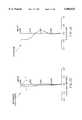
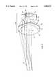
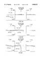
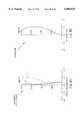
- FIG. 1shows a sectional view of the magnifier lens of a first illustrative embodiment.
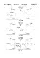
- FIGS. 2A-2Fare graphical representations of the aberrations of the magnifier lens illustrated in FIG. 1.
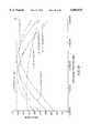
- FIG. 2Gis a plot of the through focus Modulation Transfer Function (MTF) of the magnifier lens illustrated in FIG. 1.
- MTFthrough focus Modulation Transfer Function
- FIG. 3is a sectional view of the magnifier lens system of a second illustrative embodiment.
- FIGS. 4A-4Fare graphical representations of the aberrations of the magnifier lens illustrated in FIG. 3.
- FIG. 4Gis a plot of the through focus Modulation Transfer Function (MTF) of the magnifier lens illustrated in FIG. 3.
- MTFthrough focus Modulation Transfer Function
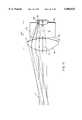
- FIG. 5shows a sectional view of the magnifier lens of a third illustrative embodiment.
- FIGS. 6A-6Fare graphical representations of the aberrations of the magnifier lens illustrated in FIG. 5.
- FIG. 6Gis a plot of the through focus Modulation Transfer Function (MTF) of the magnifier lens illustrated in FIG. 5.
- MTFthrough focus Modulation Transfer Function
- FIG. 7is a sectional view of the magnifier lens of a fourth illustrative embodiment.
- FIGS. 8A-8Fare graphical representations of the aberrations of the magnifier lens illustrated in FIG. 7.
- FIG. 8Gis a plot of the through focus Modulation Transfer Function (MTF) of the magnifier lens illustrated in FIG. 7.
- MTFthrough focus Modulation Transfer Function
- FIG. 9shows a sectional view of the magnifier lens of a fifth illustrative embodiment.
- FIGS. 10A-10Fare graphical representations of the aberrations of the magnifier lens illustrated in FIG. 9.
- FIG. 10Gis a plot of the through focus Modulation Transfer Function (MTF) of the magnifier lens illustrated in FIG. 9.
- MTFthrough focus Modulation Transfer Function
- FIG. 11is a sectional view of the magnifier lens of a sixth illustrative embodiment.
- FIGS. 12A-12Fare graphical representations of the aberrations of the magnifier lens illustrated in FIG. 11.
- FIG. 12Gis a plot of the through focus Modulation Transfer Function (MTF) of the magnifier lens illustrated in FIG. 11.
- MTFthrough focus Modulation Transfer Function
- magnifier lenswill be used to describe an optical system disclosed and claimed. However, a person skilled in the art will understand it can be used as an eyepiece with other optical components and should not be considered limited to any particular application. Note, that since the light can be directed through the lens in any direction, the eye position can be replaced by a galvanometer or a rotating polygon with some minor distortion adjustments. Thus, a "magnifier lens” constructed according to the invention could be used for scanner applications. It can also be used as a viewfinder lens in digital cameras to image a scene displayed on an electronic (preview) image display to the user's eye. The terms “front” and “rear” refer to the eye and object side of the magnifier lens, respectively.
- 10is the diaphragm of the eye or another instrument and 20 is a cover plate protecting the image display 30. Such cover plate can be easily removed with only a minor modification to the magnifier lenses described below.
- FIGS. 1, 3, 5, 7, 9, and 11The embodiments of the invention illustrated by six examples are shown respectively in FIGS. 1, 3, 5, 7, 9, and 11, and are set fourth in Tables 1 through 6.
- the surfaces Rare numbered by subscripts from the front side of the lens to the rear side of the lens.
- the thickness T of the lens elements and the spacings S between elementsare also numbered from front to rear.
- S 1corresponds to the first air space and S 2 to the second air airspace.
- spaces and thicknessesare listed on the same line as the surface preceding the space or thickness, as the case may be. All indices N d are for the helium d line of the spectrum at a wavelength ⁇ d of 587.6 nm.
- V dstands for the Abbe number (also known as a V-number) of the lens material.
- the thickness and the spacings provided in the tablesare in millimeters. All of the embodiments have a focal length of 16 mm and accept a field angle of about +/-13 degrees.
- a magnifier lens 100 of a first embodiment of the present inventionis depicted in FIG. 1.
- This magnifier lensincludes three lens elements E 1 , E 2 , E 3
- the front lens element E 1is a biconvex lens element. Its front, eye side surface is aspheric. This aspheric surface controls third and higher order monochromatic aberrations.
- the middle lens element E 2is a negative power meniscus lens element. It controls lateral and axial color aberrations.
- the convex surface of this lens elementis a diffractive surface with aspherical components. This diffractive surface minimizes secondary lateral color, provides field correction and helps balance axial color aberration.
- the concave surface of the middle lens element E 2faces the front lens element E 1 and is cemented to it, forming a cemented lens component.
- This cemented lens componentis an achromatized positive power doublet.
- the diffractive surface of the a negative power meniscus lens element E 2contributes positive power to the cemented doublet, allowing the front lens element to become less powerful. This, in turn allows the front lens element to have weaker radii of curvature than it would have otherwise, making it easier to manufacture.
- Both lens elements E 1 , E 2 forming the cemented lens componentsare plastic and can be easily molded.
- the rear lens element E 3is a meniscus lens element, concave towards the rear side--i.e., the display or object side.
- This lens element E 3is made of plastic and can be easily molded. Its index of refraction is 1.492.
- the concave surface of this meniscus lens element E 3is aspheric. This aspheric surface is positioned within 5 mm of an object to be viewed, such as the image display 30. The benefits of this aspheric surface are described in the cross-referenced patent application Ser. No. 08/562,666.
- the focal length FL 1 of the cemented lens component of the first illustrative embodimentis about 18.9 mm and its power is about 0.053.
- the focal length f 3 of the rear lens element E 3 of the first illustrative embodimentis about -69.76 millimeters and its power is about -0.0143.
- the ratio of two focal length FL 1 /f 3is -0.271.
- a magnifier lens 200 of the second embodimentis depicted in FIG. 3.
- the focal length FL 1 of the cemented lens component of the second illustrative embodimentis about 19.8 mm.
- the focal length f 3 of the rear lens element E 3 of the second illustrative embodimentis about -66.6 mm.
- the ratio of two focal length FL 1 /f 3is -0.297.
- a magnifier lens 300 of a third embodiment of the present inventionis depicted in FIG. 5.
- This magnifier lensalso includes three lens elements E 1 , E 2 , E 3
- the front lens element E 1is a biconvex lens element. Its front, eye side surface is aspheric. This aspheric surface controls third and higher order monochromatic aberrations.
- the middle lens element E 2is a negative power meniscus lens element. The middle lens element E 2 controls color aberrations.
- This middle lens element E 2 of the third embodimentis not cemented to any other lens element. It is oriented differently than the middle lens elements of the two previously discussed embodiments--the convex surface is facing lens element E 1 .
- the convex surface of this lens element E 2is a diffractive surface with aspherical components. Its function is similar to that of diffractive surfaces of the first and second embodiments. Both lens elements E 1 , E 2 are plastic and can be easily molded.
- the rear lens element E 3is a meniscus lens element, concave towards the rear side--i.e., the object side. It is made of glass with an index N d of 1.734. This relatively high index of refraction minimizes astigmatism.
- the concave surface of this rear lens element E 3is aspheric. This surface corrects field curvature, distortion and astigmatism and is positioned within 5 mm of an object to be viewed, such as the image display 30.
- the focal length f 1 of the front lens element E 1is 19.8 mm.
- the focal length f 2 of the middle lens element E 2is -20.8 mm, and the focal length f 3 of the rear lens element E 3 is 17.9 mm.
- the rear lens element E 3 of this embodimenthas positive optical power and is much stronger than its corresponding rear lens elements of the first and second embodiments.
- a magnifier lens 400 of a fourth embodiment of the present inventionis depicted in FIG. 7.
- This magnifier lensalso includes two lens elements E 1 and E 2
- the rear surface (i.e., the object facing surface) of the front lens elementis a diffractive surface. This diffractive surface controls the third and the higher order aberrations and minimizes lateral color aberration.
- the rear lens element E 2is a negative power meniscus lens element. Its convex surface is facing lens element E 1 .
- the concave surface of this rear lens element E 3is aspheric. This surface corrects field curvature, distortion and astigmatism and is positioned within 5 mm of an object to be viewed, such as the image display 30.
- the rear lens element E 2is plastic and has an index N d of 1.564 and the V-number of 32.8. Thus, the two lens elements have V-numbers that differ by about 25. This large difference in V-numbers minimizes axial color aberration.
- Both lens elements E 1 , E 2are plastic and can be easily molded.
- the focal length f 1 of the front lens element E 1is 17.98 mm.
- the focal length of the rear lens element E 2is -66.88 mm.
- the ratio of two focal length f 1 /f 2is -0.269.
- a magnifier lens 500 of the fifth embodimentis depicted in FIG. 9.
- the focal length f 1 of the front lens element of the fifth illustrative embodimentis about 17.72 mm.
- the focal length f 2 of the rear lens element E 2 of the fifth illustrative embodimentis about -36.84mm.
- the ratio of two focal lengths f 1 /f 2is -0.481.
- a magnifier lens 600 of the sixth embodimentis depicted in FIG. 11.
- the magnifier lens 600is also similar to that of the fourth embodiment, but its front lens element E 1 is glass.
- the focal length f 1 of the front lens element E 1 of the sixth illustrative embodimentis about 15.71 mm.
- the focal length f 2 of the rear lens element E 2 of the sixth illustrative embodimentis about -32.92 mm.
- the ratio of two focal lengths f 1 /f 2is -0.477.
- the magnifier lenses 100, 200, 300, 400, 500 and 600have aspheric and diffractive surfaces.
- the aspheric equation describing these aspheric surfacesis: ##EQU1## where: X is the distance along the optical axis OA;
- Yis the height from the optical axis
- Cis the reciprocal of the vertex radius of curvature of the curved lens surface
- Kis the conic coefficient
- D through Kare aspheric coefficients of 4th, 6th, 8th, 10th, 12th, 14th, 16th, and 18th order.
- the values of the aspheric coefficients for the various aspheric lens surfaces for the six lens embodimentsare provided in Tables 1 through 6.
- the diffractive surfacesare described by the following phase equation: ##EQU2## where C 1 , C 2 , C 3 , C 4 and C 5 coefficients for the diffractive surface.
- FIGS. 2A-2G, 4A-4G, 6A-6G, 8A-8G, 10A-10G, 12A-12Gdetail the performance of magnifier lenses 100, 200, 300, 400, 500 and 600, respectively. Included are ray traces for the various field positions, field curvature, distortion and lateral color plots, and the through focus MTF (Modulation Transfer Function). More specifically, FIGS. 2A, 4A, 6A, 8A, 10A and 12A are ray intercept plots (on axis field of view). FIGS. 2B, 4B, 6B, 8B, 10B and 12B are ray intercept plots for the six lens embodiments at 0, 0.7, field of view. FIGS. 2C, 4C, 6C, 8C, 10C, and 12C are ray intercept plots for the full field of view.
- FIGS. 2D-2Frepresent astigmatism, distortion and lateral color for the magnifier lens 100, respectively.
- FIG. 2Gis a plot of the modulation transfer function.
- FIGS. 4D-4G, 6D-6G, 8D-8G, 10D-10G and 12D-12Grepresent astigmatism, distortion lateral color and MTF values for the magnifier lenses of the second through six embodiments, respectively.
- the MTF curvesare plotted against the amount of defocus in millimeters, for a set of tangential (T) and Radial (R) rays for the axis; 0.7 and full field of view, for an object distance at -1500 millimeters (measured from surface 10), with a 6 mm pupil diameter, at a spacial frequency of 40.0 cycles per millimeter.
- Each curvewas substantially equally weighted for wavelength of 0.620, 0.532 and 0.485 microns.
- the depth of focusis measured at an MTF of 0.5.
- the above examplessatisfy a special need for a magnifier lenses having a relatively large stop distance of more than twice the focal length (providing an exceptionally good eye relief).
- the magnifier lensesare light weight and provide exceptional performance for their cost.
- the magnifier lensesexhibit superior quality and are color corrected over the entire visible special range while providing a half field of view of at least 10 degrees and a magnification of 16 ⁇ .
Landscapes
- Physics & Mathematics (AREA)
- General Physics & Mathematics (AREA)
- Optics & Photonics (AREA)
- Lenses (AREA)
Abstract
Description
TABLE 1______________________________________ DISTANCE OR INDEX RADIUS THICKNESS Nd Vd______________________________________10 Diaphragm 35.0R.sub.1 Asphere 10.940 1.492 57.4R.sub.2 -13.0000 2.000 1.564 32.8R.sub.3 -21.2393* .300R.sub.4 10.8692 7.172 1.492 57.4R.sub.5 Asphere______________________________________The coefficients for surfaces R.sub.1 and R.sub.5 are:Surf. R.sub.1 C = .071591 D = -.457721E-04 F = -.542308E-08 K = 0.000000 E = -.202331E-06 G = .101887E-09Vertex Radius (1/C) = 13.9683Surf. R.sub.5 C = .154784 D = .629361E-03 F = -.834232E-05 K = 0.000000 E = .944249E-04 G = .374004E-06Vertex Radius (1/C) = 6.4606*The coefficients for the diffractive surface R.sub.3 are:C.sub.1 = 2.0882E-03 C.sub.3 = -1.7760E-09 C.sub.5 = 0C.sub.2 = -5.8201E-06 C.sub.4 = 0λ.sub.0 = 532.0 nm______________________________________
TABLE 2______________________________________ DISTANCE OR INDEX RADIUS THICKNESS Nd Vd______________________________________10 Diaphragm 35.0R.sub.1 Asphere 11.911 1.492 57.4R.sub.2 -13.0000 2.900 1.564 32.8R.sub.3 -21.0022* .3R.sub.4 10.6081 6.650 1.734 51.1R.sub.5 Asphere______________________________________The coefficients for surfaces R.sub.1 and R.sub.5 are:Surf. R.sub.1 C = .066174 D = -.338879E-04 F = -.880154E-09 K = 0.000000 E = -.245240E-06 G = .175546E-10Vertex Radius (1/C) = 15.1116Surf. R.sub.5 C = .156204 D = .536306E-03 F = -.551321E-06 K = 0.000000 E = .136368E-04 G = .648670E-07Vertex Radius (1/C) = 6.4019*The coefficients for the diffractive surface R.sub.3 are:C.sub.1 = 2.1177E-03 C.sub.3 = 9.1723E-09 C.sub.5 = 1.1957E-12C.sub.2 = -5.4417E-06 C.sub.4 = 2.4296E-10λ.sub.0 = 532.0 nm______________________________________
TABLE 3______________________________________ DISTANCE OR INDEX RADIUS THICKNESS Nd Vd______________________________________10 Diaphragm 35.0R.sub.1 Asphere 9.173 1.492 57.4R.sub.2 -34.7079R.sub.3 32.3571* 3.862 1.564 32.8R.sub.4 7.8500 .476R.sub.5 8.4785 9.000 1.734 51.1R.sub.6 Asphere______________________________________The coefficients for surfaces R.sub.1 and R.sub.6 are:Surf. R.sub.1 C = .080183 D = -.585403E-04 F = .361280E-08 K = 0.000000 E = -.302823E-06 G = -.948954E-10Vertex Radius (1/C) = 12.4714Surf. R.sub.6 C = .076930 D = .121680E-02 F = .358288E-05 K = 0.000000 E = -.412049E-04 G = -.650446E-07Vertex Radius (1/C) = 12.9988*The coefficients for the diffractive surface R.sub.3 are:C.sub.1 = 1.5060E-031.8330E-07 C.sub.3 = C.sub.5 = 0C.sub.2 = 1.0030E-05 C.sub.4 = 1.2055E-09λ.sub.0 = 532.0 nm______________________________________
TABLE 4______________________________________ DISTANCE OR INDEX RADIUS THICKNESS Nd Vd______________________________________10 Diaphragm 35.0R.sub.1 Asphere 9.977 1.492 57.4R.sub.2 -28.4048* 1.759R.sub.3 23.4922 10.000 1.564 32.8R.sub.4 Asphere______________________________________The coefficients for surfaces R.sub.1 and R.sub.4 are:Surf. R.sub.1 C = .080449 D = -.589619B-04 F = .126216E-07 K = 0.000000 E= -.860812E-06 G= -.184134E-09Vertex Radius (1/C) = 12.4303Surf. R.sub.4 C = .081440 D = .177622E-02 F = .591441E-05 K = 0.000000 E = .-.677103E-04 G = -.778871E-07Vertex Radius (1/C) = 12.2790*The coefficients for the diffractive surface R.sub.2 are:C.sub.1 = 2.0640E-03 C.sub.3 = 9.6018E-092.5864E-12 C.sub.5 =C.sub.2 = 2.0200E-06 C.sub.4 = 3.0596E-10λ.sub.0 = 532.0 nm______________________________________
TABLE 5______________________________________ DISTANCE OR INDEX RADIUS THICKNESS Nd Vd______________________________________10 Diaphragm 35.0R.sub.1 Asphere 10.000 1.492 57.4R.sub.2 -22.9432* 1.962R.sub.3 29.4381 10.000 1.805 25.4R.sub.4 Asphere______________________________________The coefficients for surfaces R.sub.1 and R.sub.4 are:Surf. R.sub.1 C = .082888 D = .751750E-04 F = .994988E-08 K = 0.000000 E = -.857001E-06 G = -.177057E-09Vertex Radius (1/C) = 12.0645Surf. R.sub.4 C = .089849 D= .134474E-02 F = .855280E-05 K = 0.000000 E = -.634209E-04 G = -.280603E-06Vertex Radius (1/C) = 11.1298*The coefficients for the diffractive surface R.sub.2 are:C.sub.1 = -1.9373E-03 C.sub.3 = 1.0324E-07 C.sub.5 = 7.4082E-12C.sub.2 = 7.7669E-06 C.sub.4 = 1.4486E-09λ.sub.0 = 532.0 nm______________________________________
TABLE 6______________________________________ DISTANCE OR INDEX RADIUS THICKNESS Nd Vd______________________________________10 Diaphragm 35.0R.sub.1 Asphere 9.677 1.589 61.3R.sub.2 -27.4509 .25R.sub.3 59.2756* 10.000 1.564 32.8R.sub.4 Asphere______________________________________The coefficients for surfaces R.sub.1 and R.sub.4 are:Surf. R.sub.1 C = .081755 D = .480967E-04 F = .131906E-07 K = 0.000000 E = -.105922E-05 G = -.186885E-09Vertex Radius (1/C) = 12.2316Surf. R.sub.4 C = .085831 D = .111194E-02 F = .237160E-05 K = 0.000000 E = -.131699E-04 G = -.241665E-07Vertex Radius (1/C) = 11.6508*The coefficients for the diffractive surface R.sub.3 are:C.sub.1 = -2.2262E-03 C.sub.3 = 9.01OOE-07 C.sub.5 = -9.3902E-11C.sub.2 = 2.1628E-05 C.sub.4 = 1.5392E-08λ.sub.0 = 532.0 nm______________________________________
Claims (6)
Priority Applications (1)
| Application Number | Priority Date | Filing Date | Title |
|---|---|---|---|
| US08/964,488US5886825A (en) | 1997-11-05 | 1997-11-05 | Magnifier Lens |
Applications Claiming Priority (1)
| Application Number | Priority Date | Filing Date | Title |
|---|---|---|---|
| US08/964,488US5886825A (en) | 1997-11-05 | 1997-11-05 | Magnifier Lens |
Publications (1)
| Publication Number | Publication Date |
|---|---|
| US5886825Atrue US5886825A (en) | 1999-03-23 |
Family
ID=25508598
Family Applications (1)
| Application Number | Title | Priority Date | Filing Date |
|---|---|---|---|
| US08/964,488Expired - LifetimeUS5886825A (en) | 1997-11-05 | 1997-11-05 | Magnifier Lens |
Country Status (1)
| Country | Link |
|---|---|
| US (1) | US5886825A (en) |
Cited By (14)
| Publication number | Priority date | Publication date | Assignee | Title |
|---|---|---|---|---|
| US20020149860A1 (en)* | 2001-01-30 | 2002-10-17 | Yuji Miyauchi | Image pickup system |
| US6704149B2 (en) | 1998-04-21 | 2004-03-09 | Minolta Co., Ltd. | Lens optical system |
| US6741403B2 (en)* | 2002-05-31 | 2004-05-25 | Largan Precision Co., Ltd. | Hybrid lens system |
| US20040165283A1 (en)* | 2003-02-24 | 2004-08-26 | Cahall Scott C. | Optical magnifier suitable for use with a microdisplay device |
| US7295387B1 (en) | 1998-04-21 | 2007-11-13 | Minolta Co., Ltd. | Lens optical system |
| CN100462770C (en)* | 2004-10-28 | 2009-02-18 | 清华大学 | Micro Camera Lens System |
| US20110181964A1 (en)* | 2010-01-26 | 2011-07-28 | Eschenbach Optik Gmbh | Magnifying glass |
| CN101470262B (en)* | 2007-12-27 | 2011-08-17 | 比亚迪股份有限公司 | Optical imaging device of miniature display eyepiece |
| US20110241518A1 (en)* | 2006-07-31 | 2011-10-06 | 3M Innovative Property Company | Led source with hollow collection lens |
| EP2233959A4 (en)* | 2007-12-20 | 2014-02-19 | Nikon Corp | Eyepiece system and optical device |
| CN104280877A (en)* | 2014-10-28 | 2015-01-14 | 成都贝思达光电科技有限公司 | Refraction and diffraction mixed eyepiece used for video glasses |
| US10067334B2 (en) | 2016-04-27 | 2018-09-04 | Tele Vue Optics, Inc. | Optical magnifier |
| FR3082319A1 (en)* | 2018-06-11 | 2019-12-13 | Daniel AIT-YAHIATENE | OBJECTIVE FOR FOCUSING IMAGES |
| WO2022034231A3 (en)* | 2020-08-13 | 2022-05-27 | Carl Zeiss Ag | Optical system |
Citations (7)
| Publication number | Priority date | Publication date | Assignee | Title |
|---|---|---|---|---|
| US3158677A (en)* | 1960-12-19 | 1964-11-24 | Pierre J B Lacomme | Wide angle oculars |
| US5162945A (en)* | 1989-06-27 | 1992-11-10 | Asahi Kogaku Kogyo K.K. | Ocular lens system |
| US5202795A (en)* | 1990-10-23 | 1993-04-13 | Olympus Optical Co., Ltd. | Eyepieces |
| US5440197A (en)* | 1993-10-05 | 1995-08-08 | Tir Technologies, Inc. | Backlighting apparatus for uniformly illuminating a display panel |
| US5446588A (en)* | 1994-07-29 | 1995-08-29 | The University Of Rochester | Wide-angle eyepiece optical system employing refractive and diffractive optical elements |
| US5619379A (en)* | 1994-09-07 | 1997-04-08 | Nikon Corporation | Aspherical surface ocular lens |
| US5703721A (en)* | 1995-11-27 | 1997-12-30 | Eastman Kodak Company | Optical magnifier |
- 1997
- 1997-11-05USUS08/964,488patent/US5886825A/ennot_activeExpired - Lifetime
Patent Citations (7)
| Publication number | Priority date | Publication date | Assignee | Title |
|---|---|---|---|---|
| US3158677A (en)* | 1960-12-19 | 1964-11-24 | Pierre J B Lacomme | Wide angle oculars |
| US5162945A (en)* | 1989-06-27 | 1992-11-10 | Asahi Kogaku Kogyo K.K. | Ocular lens system |
| US5202795A (en)* | 1990-10-23 | 1993-04-13 | Olympus Optical Co., Ltd. | Eyepieces |
| US5440197A (en)* | 1993-10-05 | 1995-08-08 | Tir Technologies, Inc. | Backlighting apparatus for uniformly illuminating a display panel |
| US5446588A (en)* | 1994-07-29 | 1995-08-29 | The University Of Rochester | Wide-angle eyepiece optical system employing refractive and diffractive optical elements |
| US5619379A (en)* | 1994-09-07 | 1997-04-08 | Nikon Corporation | Aspherical surface ocular lens |
| US5703721A (en)* | 1995-11-27 | 1997-12-30 | Eastman Kodak Company | Optical magnifier |
Non-Patent Citations (4)
| Title |
|---|
| Cyberdisplay , 320 Monochrome Display Specifications, Kopin Corp. pp. 3 19 through 3 20. 1997.* |
| Cyberdisplay ™, 320 Monochrome Display Specifications, Kopin Corp. pp. 3-19 through 3-20. ©1997. |
| Military Standardization Handbook, Optical Design, Handbook number 141, Oct. 5, 1962 pp. 14 4 through 14 19.* |
| Military Standardization Handbook, Optical Design, Handbook number 141, Oct. 5, 1962 pp. 14-4 through 14-19. |
Cited By (29)
| Publication number | Priority date | Publication date | Assignee | Title |
|---|---|---|---|---|
| US7295387B1 (en) | 1998-04-21 | 2007-11-13 | Minolta Co., Ltd. | Lens optical system |
| US6704149B2 (en) | 1998-04-21 | 2004-03-09 | Minolta Co., Ltd. | Lens optical system |
| US7529031B2 (en) | 2001-01-30 | 2009-05-05 | Olympus Corporation | Image pickup system |
| USRE40563E1 (en)* | 2001-01-30 | 2008-11-04 | Olympus Corporation | Image pickup system |
| US7605982B2 (en) | 2001-01-30 | 2009-10-20 | Olympus Corporation | Image pickup system |
| US7593162B2 (en) | 2001-01-30 | 2009-09-22 | Olympus Corporation | Image pickup system |
| US7599121B2 (en) | 2001-01-30 | 2009-10-06 | Olympus Corporation | Image pickup system |
| US6958863B2 (en)* | 2001-01-30 | 2005-10-25 | Olympus Corporation | Image pickup system |
| US20060262212A1 (en)* | 2001-01-30 | 2006-11-23 | Yuji Miyauchi | Image pickup system |
| US20060274181A1 (en)* | 2001-01-30 | 2006-12-07 | Yuji Miyauchi | Image pickup system |
| US20060274182A1 (en)* | 2001-01-30 | 2006-12-07 | Yuji Miyauchi | Image pickup system |
| US20020149860A1 (en)* | 2001-01-30 | 2002-10-17 | Yuji Miyauchi | Image pickup system |
| US6741403B2 (en)* | 2002-05-31 | 2004-05-25 | Largan Precision Co., Ltd. | Hybrid lens system |
| US6847494B2 (en) | 2003-02-24 | 2005-01-25 | Eastman Kodak Company | Optical magnifier suitable for use with a microdisplay device |
| US20040165283A1 (en)* | 2003-02-24 | 2004-08-26 | Cahall Scott C. | Optical magnifier suitable for use with a microdisplay device |
| US6785054B1 (en) | 2003-02-24 | 2004-08-31 | Eastman Kodak Company | Optical magnifier suitable for use with a microdisplay device |
| US20040165278A1 (en)* | 2003-02-24 | 2004-08-26 | Eastman Kodak Company | Optical magnifier suitable for use with a microdisplay device |
| CN100462770C (en)* | 2004-10-28 | 2009-02-18 | 清华大学 | Micro Camera Lens System |
| US8274220B2 (en)* | 2006-07-31 | 2012-09-25 | 3M Innovative Properties Company | LED source with hollow collection lens |
| US20110241518A1 (en)* | 2006-07-31 | 2011-10-06 | 3M Innovative Property Company | Led source with hollow collection lens |
| EP2233959A4 (en)* | 2007-12-20 | 2014-02-19 | Nikon Corp | Eyepiece system and optical device |
| CN101470262B (en)* | 2007-12-27 | 2011-08-17 | 比亚迪股份有限公司 | Optical imaging device of miniature display eyepiece |
| US20110181964A1 (en)* | 2010-01-26 | 2011-07-28 | Eschenbach Optik Gmbh | Magnifying glass |
| CN104280877A (en)* | 2014-10-28 | 2015-01-14 | 成都贝思达光电科技有限公司 | Refraction and diffraction mixed eyepiece used for video glasses |
| US10067334B2 (en) | 2016-04-27 | 2018-09-04 | Tele Vue Optics, Inc. | Optical magnifier |
| FR3082319A1 (en)* | 2018-06-11 | 2019-12-13 | Daniel AIT-YAHIATENE | OBJECTIVE FOR FOCUSING IMAGES |
| WO2022034231A3 (en)* | 2020-08-13 | 2022-05-27 | Carl Zeiss Ag | Optical system |
| AT526260A5 (en)* | 2020-08-13 | 2023-11-15 | Zeiss Carl Ag | Optical system |
| AT526260B1 (en)* | 2020-08-13 | 2024-02-15 | Zeiss Carl Ag | Optical system |
Similar Documents
| Publication | Publication Date | Title |
|---|---|---|
| US5446588A (en) | Wide-angle eyepiece optical system employing refractive and diffractive optical elements | |
| US5559637A (en) | Field curvature corrector | |
| US5677797A (en) | Method for correcting field curvature | |
| US6980365B2 (en) | Diffractive lens optical design | |
| EP0799433B1 (en) | Variable power lens systems for producing small images | |
| US5886825A (en) | Magnifier Lens | |
| JP3387338B2 (en) | Eyepiece optical system and eyepiece image display device | |
| US6847494B2 (en) | Optical magnifier suitable for use with a microdisplay device | |
| US7046454B2 (en) | Two-group zoom lens | |
| US6028711A (en) | Reading lens | |
| US4217048A (en) | Viewfinder capable of adjusting diopter | |
| US5909322A (en) | Magnifier lens | |
| CN117724249A (en) | Visual optical system | |
| JPH10170818A (en) | Optical system and optical equipment using the same | |
| US5691850A (en) | Eyepiece | |
| US5959785A (en) | Achromatic lens system including a diffraction lens | |
| CN118348665A (en) | Optical lens | |
| EP0385698B1 (en) | Projection lens and projection television system using the same | |
| US5867326A (en) | Zoom lens | |
| US20030112530A1 (en) | Single focus lens | |
| JPH1073760A (en) | Lens system having diffraction type optical element | |
| US5703721A (en) | Optical magnifier | |
| WO2007006017A2 (en) | Five-element optical device | |
| JP7581059B2 (en) | Optical system and imaging device | |
| US6804462B2 (en) | Camera provided with eyepiece |
Legal Events
| Date | Code | Title | Description |
|---|---|---|---|
| AS | Assignment | Owner name:EASTMAN KODAK COMPANY, NEW YORK Free format text:ASSIGNMENT OF ASSIGNORS INTEREST;ASSIGNOR:BIETRY, JOSEPH R.;REEL/FRAME:008880/0818 Effective date:19971105 | |
| STCF | Information on status: patent grant | Free format text:PATENTED CASE | |
| FPAY | Fee payment | Year of fee payment:4 | |
| FEPP | Fee payment procedure | Free format text:PAYOR NUMBER ASSIGNED (ORIGINAL EVENT CODE: ASPN); ENTITY STATUS OF PATENT OWNER: LARGE ENTITY | |
| FPAY | Fee payment | Year of fee payment:8 | |
| FPAY | Fee payment | Year of fee payment:12 | |
| AS | Assignment | Owner name:CITICORP NORTH AMERICA, INC., AS AGENT, NEW YORK Free format text:SECURITY INTEREST;ASSIGNORS:EASTMAN KODAK COMPANY;PAKON, INC.;REEL/FRAME:028201/0420 Effective date:20120215 | |
| FEPP | Fee payment procedure | Free format text:PAYER NUMBER DE-ASSIGNED (ORIGINAL EVENT CODE: RMPN); ENTITY STATUS OF PATENT OWNER: LARGE ENTITY Free format text:PAYOR NUMBER ASSIGNED (ORIGINAL EVENT CODE: ASPN); ENTITY STATUS OF PATENT OWNER: LARGE ENTITY | |
| AS | Assignment | Owner name:CREO MANUFACTURING AMERICA LLC, WYOMING Free format text:PATENT RELEASE;ASSIGNORS:CITICORP NORTH AMERICA, INC.;WILMINGTON TRUST, NATIONAL ASSOCIATION;REEL/FRAME:029913/0001 Effective date:20130201 Owner name:FPC INC., CALIFORNIA Free format text:PATENT RELEASE;ASSIGNORS:CITICORP NORTH AMERICA, INC.;WILMINGTON TRUST, NATIONAL ASSOCIATION;REEL/FRAME:029913/0001 Effective date:20130201 Owner name:FAR EAST DEVELOPMENT LTD., NEW YORK Free format text:PATENT RELEASE;ASSIGNORS:CITICORP NORTH AMERICA, INC.;WILMINGTON TRUST, NATIONAL ASSOCIATION;REEL/FRAME:029913/0001 Effective date:20130201 Owner name:KODAK AVIATION LEASING LLC, NEW YORK Free format text:PATENT RELEASE;ASSIGNORS:CITICORP NORTH AMERICA, INC.;WILMINGTON TRUST, NATIONAL ASSOCIATION;REEL/FRAME:029913/0001 Effective date:20130201 Owner name:PAKON, INC., INDIANA Free format text:PATENT RELEASE;ASSIGNORS:CITICORP NORTH AMERICA, INC.;WILMINGTON TRUST, NATIONAL ASSOCIATION;REEL/FRAME:029913/0001 Effective date:20130201 Owner name:QUALEX INC., NORTH CAROLINA Free format text:PATENT RELEASE;ASSIGNORS:CITICORP NORTH AMERICA, INC.;WILMINGTON TRUST, NATIONAL ASSOCIATION;REEL/FRAME:029913/0001 Effective date:20130201 Owner name:KODAK PORTUGUESA LIMITED, NEW YORK Free format text:PATENT RELEASE;ASSIGNORS:CITICORP NORTH AMERICA, INC.;WILMINGTON TRUST, NATIONAL ASSOCIATION;REEL/FRAME:029913/0001 Effective date:20130201 Owner name:LASER-PACIFIC MEDIA CORPORATION, NEW YORK Free format text:PATENT RELEASE;ASSIGNORS:CITICORP NORTH AMERICA, INC.;WILMINGTON TRUST, NATIONAL ASSOCIATION;REEL/FRAME:029913/0001 Effective date:20130201 Owner name:KODAK REALTY, INC., NEW YORK Free format text:PATENT RELEASE;ASSIGNORS:CITICORP NORTH AMERICA, INC.;WILMINGTON TRUST, NATIONAL ASSOCIATION;REEL/FRAME:029913/0001 Effective date:20130201 Owner name:EASTMAN KODAK COMPANY, NEW YORK Free format text:PATENT RELEASE;ASSIGNORS:CITICORP NORTH AMERICA, INC.;WILMINGTON TRUST, NATIONAL ASSOCIATION;REEL/FRAME:029913/0001 Effective date:20130201 Owner name:KODAK (NEAR EAST), INC., NEW YORK Free format text:PATENT RELEASE;ASSIGNORS:CITICORP NORTH AMERICA, INC.;WILMINGTON TRUST, NATIONAL ASSOCIATION;REEL/FRAME:029913/0001 Effective date:20130201 Owner name:NPEC INC., NEW YORK Free format text:PATENT RELEASE;ASSIGNORS:CITICORP NORTH AMERICA, INC.;WILMINGTON TRUST, NATIONAL ASSOCIATION;REEL/FRAME:029913/0001 Effective date:20130201 Owner name:EASTMAN KODAK INTERNATIONAL CAPITAL COMPANY, INC., Free format text:PATENT RELEASE;ASSIGNORS:CITICORP NORTH AMERICA, INC.;WILMINGTON TRUST, NATIONAL ASSOCIATION;REEL/FRAME:029913/0001 Effective date:20130201 Owner name:KODAK PHILIPPINES, LTD., NEW YORK Free format text:PATENT RELEASE;ASSIGNORS:CITICORP NORTH AMERICA, INC.;WILMINGTON TRUST, NATIONAL ASSOCIATION;REEL/FRAME:029913/0001 Effective date:20130201 Owner name:KODAK AMERICAS, LTD., NEW YORK Free format text:PATENT RELEASE;ASSIGNORS:CITICORP NORTH AMERICA, INC.;WILMINGTON TRUST, NATIONAL ASSOCIATION;REEL/FRAME:029913/0001 Effective date:20130201 Owner name:KODAK IMAGING NETWORK, INC., CALIFORNIA Free format text:PATENT RELEASE;ASSIGNORS:CITICORP NORTH AMERICA, INC.;WILMINGTON TRUST, NATIONAL ASSOCIATION;REEL/FRAME:029913/0001 Effective date:20130201 | |
| AS | Assignment | Owner name:INTELLECTUAL VENTURES FUND 83 LLC, NEVADA Free format text:ASSIGNMENT OF ASSIGNORS INTEREST;ASSIGNOR:EASTMAN KODAK COMPANY;REEL/FRAME:030149/0863 Effective date:20130201 | |
| AS | Assignment | Owner name:MONUMENT PEAK VENTURES, LLC, TEXAS Free format text:ASSIGNMENT OF ASSIGNORS INTEREST;ASSIGNOR:INTELLECTUAL VENTURES FUND 83 LLC;REEL/FRAME:041941/0079 Effective date:20170215 | |
| AS | Assignment | Owner name:MONUMENT PEAK VENTURES, LLC, TEXAS Free format text:RELEASE BY SECURED PARTY;ASSIGNOR:INTELLECTUAL VENTURES FUND 83 LLC;REEL/FRAME:064599/0304 Effective date:20230728 |