US5886822A - Image combining system for eyeglasses and face masks - Google Patents
Image combining system for eyeglasses and face masksDownload PDFInfo
- Publication number
- US5886822A US5886822AUS08/844,098US84409897AUS5886822AUS 5886822 AUS5886822 AUS 5886822AUS 84409897 AUS84409897 AUS 84409897AUS 5886822 AUS5886822 AUS 5886822A
- Authority
- US
- United States
- Prior art keywords
- lens
- optical
- image
- insert
- user
- Prior art date
- Legal status (The legal status is an assumption and is not a legal conclusion. Google has not performed a legal analysis and makes no representation as to the accuracy of the status listed.)
- Expired - Lifetime
Links
- 230000003287optical effectEffects0.000claimsabstractdescription186
- 230000037361pathwayEffects0.000claimsabstract50
- 239000000463materialSubstances0.000claimsdescription21
- 210000003128headAnatomy0.000claimsdescription20
- 238000000576coating methodMethods0.000claimsdescription17
- 239000000835fiberSubstances0.000claimsdescription16
- 239000004973liquid crystal related substanceSubstances0.000claimsdescription14
- 230000010287polarizationEffects0.000claimsdescription10
- 239000011248coating agentSubstances0.000claimsdescription9
- 239000011159matrix materialSubstances0.000claimsdescription7
- 239000013307optical fiberSubstances0.000claimsdescription7
- 230000001427coherent effectEffects0.000claimsdescription6
- 238000012937correctionMethods0.000claimsdescription5
- 238000005286illuminationMethods0.000claimsdescription4
- 238000003754machiningMethods0.000claimsdescription4
- 230000004075alterationEffects0.000claimsdescription3
- 238000000465mouldingMethods0.000claimsdescription3
- 238000005266castingMethods0.000claimsdescription2
- 239000013056hazardous productSubstances0.000claimsdescription2
- 230000010354integrationEffects0.000abstractdescription4
- 238000013459approachMethods0.000description15
- 238000013461designMethods0.000description15
- 239000011521glassSubstances0.000description13
- 238000000034methodMethods0.000description12
- 230000008901benefitEffects0.000description10
- 210000001747pupilAnatomy0.000description9
- 150000001875compoundsChemical class0.000description7
- 239000007787solidSubstances0.000description7
- 230000008859changeEffects0.000description6
- 230000000694effectsEffects0.000description6
- 238000007654immersionMethods0.000description6
- 230000006378damageEffects0.000description5
- 210000001525retinaAnatomy0.000description5
- 230000006870functionEffects0.000description4
- 230000006872improvementEffects0.000description4
- 230000007246mechanismEffects0.000description4
- VYPSYNLAJGMNEJ-UHFFFAOYSA-NSilicium dioxideChemical compoundO=[Si]=OVYPSYNLAJGMNEJ-UHFFFAOYSA-N0.000description3
- 230000005540biological transmissionEffects0.000description3
- 239000005350fused silica glassSubstances0.000description3
- 238000003384imaging methodMethods0.000description3
- 239000002537cosmeticSubstances0.000description2
- 238000001514detection methodMethods0.000description2
- 238000005516engineering processMethods0.000description2
- 239000012530fluidSubstances0.000description2
- 238000001746injection mouldingMethods0.000description2
- 238000003780insertionMethods0.000description2
- 230000037431insertionEffects0.000description2
- 239000002184metalSubstances0.000description2
- 230000005855radiationEffects0.000description2
- 230000009467reductionEffects0.000description2
- 230000000717retained effectEffects0.000description2
- 230000001360synchronised effectEffects0.000description2
- 239000010409thin filmSubstances0.000description2
- 239000004593EpoxySubstances0.000description1
- XUIMIQQOPSSXEZ-UHFFFAOYSA-NSiliconChemical compound[Si]XUIMIQQOPSSXEZ-UHFFFAOYSA-N0.000description1
- 208000027418Wounds and injuryDiseases0.000description1
- 238000010521absorption reactionMethods0.000description1
- 230000002238attenuated effectEffects0.000description1
- 230000009286beneficial effectEffects0.000description1
- 230000015572biosynthetic processEffects0.000description1
- 230000015556catabolic processEffects0.000description1
- 239000004568cementSubstances0.000description1
- 239000003086colorantSubstances0.000description1
- 239000012141concentrateSubstances0.000description1
- 230000007423decreaseEffects0.000description1
- 238000006731degradation reactionMethods0.000description1
- 230000001419dependent effectEffects0.000description1
- 230000001627detrimental effectEffects0.000description1
- 238000011161developmentMethods0.000description1
- 238000009792diffusion processMethods0.000description1
- 239000006185dispersionSubstances0.000description1
- 230000009189divingEffects0.000description1
- 239000003814drugSubstances0.000description1
- 230000008030eliminationEffects0.000description1
- 238000003379elimination reactionMethods0.000description1
- 231100000040eye damageToxicity0.000description1
- 230000002349favourable effectEffects0.000description1
- 239000010408filmSubstances0.000description1
- 230000004907fluxEffects0.000description1
- 230000005484gravityEffects0.000description1
- 238000010348incorporationMethods0.000description1
- 238000002347injectionMethods0.000description1
- 239000007924injectionSubstances0.000description1
- 208000014674injuryDiseases0.000description1
- 238000007689inspectionMethods0.000description1
- 238000005304joiningMethods0.000description1
- 239000007788liquidSubstances0.000description1
- 230000033001locomotionEffects0.000description1
- 238000002156mixingMethods0.000description1
- 230000004048modificationEffects0.000description1
- 238000012986modificationMethods0.000description1
- 239000012778molding materialSubstances0.000description1
- 238000004806packaging method and processMethods0.000description1
- 239000004033plasticSubstances0.000description1
- 229920003023plasticPolymers0.000description1
- 229920003229poly(methyl methacrylate)Polymers0.000description1
- 239000004417polycarbonateSubstances0.000description1
- 229920000515polycarbonatePolymers0.000description1
- 229920000642polymerPolymers0.000description1
- 239000004926polymethyl methacrylateSubstances0.000description1
- 238000004382pottingMethods0.000description1
- 230000008569processEffects0.000description1
- 238000002310reflectometryMethods0.000description1
- 230000001105regulatory effectEffects0.000description1
- 238000011160researchMethods0.000description1
- 230000004044responseEffects0.000description1
- 230000002441reversible effectEffects0.000description1
- 238000007493shaping processMethods0.000description1
- 229910052710siliconInorganic materials0.000description1
- 239000010703siliconSubstances0.000description1
- 125000006850spacer groupChemical group0.000description1
- 230000003595spectral effectEffects0.000description1
- 238000013519translationMethods0.000description1
- 239000011800void materialSubstances0.000description1
- XLYOFNOQVPJJNP-UHFFFAOYSA-NwaterSubstancesOXLYOFNOQVPJJNP-UHFFFAOYSA-N0.000description1
Images


Classifications
- G—PHYSICS
- G02—OPTICS
- G02B—OPTICAL ELEMENTS, SYSTEMS OR APPARATUS
- G02B27/00—Optical systems or apparatus not provided for by any of the groups G02B1/00 - G02B26/00, G02B30/00
- G02B27/10—Beam splitting or combining systems
- G02B27/12—Beam splitting or combining systems operating by refraction only
- G02B27/126—The splitting element being a prism or prismatic array, including systems based on total internal reflection
- G—PHYSICS
- G02—OPTICS
- G02B—OPTICAL ELEMENTS, SYSTEMS OR APPARATUS
- G02B27/00—Optical systems or apparatus not provided for by any of the groups G02B1/00 - G02B26/00, G02B30/00
- G02B27/01—Head-up displays
- G02B27/017—Head mounted
- G02B27/0172—Head mounted characterised by optical features
- G—PHYSICS
- G02—OPTICS
- G02B—OPTICAL ELEMENTS, SYSTEMS OR APPARATUS
- G02B27/00—Optical systems or apparatus not provided for by any of the groups G02B1/00 - G02B26/00, G02B30/00
- G02B27/10—Beam splitting or combining systems
- G02B27/14—Beam splitting or combining systems operating by reflection only
- G02B27/143—Beam splitting or combining systems operating by reflection only using macroscopically faceted or segmented reflective surfaces
- G—PHYSICS
- G02—OPTICS
- G02B—OPTICAL ELEMENTS, SYSTEMS OR APPARATUS
- G02B27/00—Optical systems or apparatus not provided for by any of the groups G02B1/00 - G02B26/00, G02B30/00
- G02B27/10—Beam splitting or combining systems
- G02B27/14—Beam splitting or combining systems operating by reflection only
- G02B27/144—Beam splitting or combining systems operating by reflection only using partially transparent surfaces without spectral selectivity
- G—PHYSICS
- G02—OPTICS
- G02B—OPTICAL ELEMENTS, SYSTEMS OR APPARATUS
- G02B27/00—Optical systems or apparatus not provided for by any of the groups G02B1/00 - G02B26/00, G02B30/00
- G02B27/10—Beam splitting or combining systems
- G02B27/14—Beam splitting or combining systems operating by reflection only
- G02B27/145—Beam splitting or combining systems operating by reflection only having sequential partially reflecting surfaces
- G—PHYSICS
- G02—OPTICS
- G02B—OPTICAL ELEMENTS, SYSTEMS OR APPARATUS
- G02B27/00—Optical systems or apparatus not provided for by any of the groups G02B1/00 - G02B26/00, G02B30/00
- G02B27/01—Head-up displays
- G02B27/0101—Head-up displays characterised by optical features
- G02B2027/011—Head-up displays characterised by optical features comprising device for correcting geometrical aberrations, distortion
- G—PHYSICS
- G02—OPTICS
- G02B—OPTICAL ELEMENTS, SYSTEMS OR APPARATUS
- G02B27/00—Optical systems or apparatus not provided for by any of the groups G02B1/00 - G02B26/00, G02B30/00
- G02B27/01—Head-up displays
- G02B27/0101—Head-up displays characterised by optical features
- G02B2027/0118—Head-up displays characterised by optical features comprising devices for improving the contrast of the display / brillance control visibility
- G—PHYSICS
- G02—OPTICS
- G02B—OPTICAL ELEMENTS, SYSTEMS OR APPARATUS
- G02B27/00—Optical systems or apparatus not provided for by any of the groups G02B1/00 - G02B26/00, G02B30/00
- G02B27/01—Head-up displays
- G02B27/0101—Head-up displays characterised by optical features
- G02B2027/0123—Head-up displays characterised by optical features comprising devices increasing the field of view
- G—PHYSICS
- G02—OPTICS
- G02B—OPTICAL ELEMENTS, SYSTEMS OR APPARATUS
- G02B27/00—Optical systems or apparatus not provided for by any of the groups G02B1/00 - G02B26/00, G02B30/00
- G02B27/01—Head-up displays
- G02B27/0101—Head-up displays characterised by optical features
- G02B2027/0132—Head-up displays characterised by optical features comprising binocular systems
- G—PHYSICS
- G02—OPTICS
- G02B—OPTICAL ELEMENTS, SYSTEMS OR APPARATUS
- G02B27/00—Optical systems or apparatus not provided for by any of the groups G02B1/00 - G02B26/00, G02B30/00
- G02B27/01—Head-up displays
- G02B27/017—Head mounted
- G02B27/0172—Head mounted characterised by optical features
- G02B2027/0174—Head mounted characterised by optical features holographic
- G—PHYSICS
- G02—OPTICS
- G02B—OPTICAL ELEMENTS, SYSTEMS OR APPARATUS
- G02B27/00—Optical systems or apparatus not provided for by any of the groups G02B1/00 - G02B26/00, G02B30/00
- G02B27/01—Head-up displays
- G02B27/017—Head mounted
- G02B2027/0178—Eyeglass type
- G—PHYSICS
- G02—OPTICS
- G02B—OPTICAL ELEMENTS, SYSTEMS OR APPARATUS
- G02B5/00—Optical elements other than lenses
- G02B5/30—Polarising elements
- G—PHYSICS
- G02—OPTICS
- G02B—OPTICAL ELEMENTS, SYSTEMS OR APPARATUS
- G02B6/00—Light guides; Structural details of arrangements comprising light guides and other optical elements, e.g. couplings
Definitions
- Head mounted image displayse.g. helmets, goggles, and eyeglasses incorporating miniature displays
- other compact display systemswhich provide data in alphanumeric, video, or graphic form have applications in avionics, medicine, entertainment, and wearable computers, as well as numerous other fields. See for example U.S. Pat. Nos. 5,348,477, 5,281,960, 4,806,001 and 5,162,828.
- see-through systemsin which the displayed electronic image is combined with the ambient imagery so that the user can see both images
- see-around systemsin which the displayed image occludes a part of the ambient imagery
- full-immersion systemsin which the entire ambient image is blocked, so that the user sees only the electronically generated image.
- All three types of systemsuse various means, including lenses and the like, to project the image into the viewer's eyes.
- the simplest systemsare of the see-around type in which the electronic display is provided with one or more lenses and suspended in front of the user's eyes.
- a principal limitation of the deviceis that the display and optical system must be moved with respect to the head, or the head must be moved, to enable the user to see ambient imagery in the occluded field.
- a second limitation of such devicesis that the device is suspended from the head (or helmet, strap or other support borne by the head), so that the mass of apparatus adds an undesirable weight and/or torque to the head.
- a third limitation of the deviceis that position of the exit pupil of the optical system cannot be fixed accurately, meaning that the exit pupil of the optical system must be large enough to accommodate various motions of the device that occur during use.
- Full-immersion systemshave many of the same limitations as see-around systems.
- the head mounted systemmust be removed to view any ambient imagery.
- the systemscomprise displays and lens systems similar to the see-around display, or comprise a display, lens system and reflective screen. These systems involve high weight, torque and volume.
- See-through systemsinvolve the most complex optical designs.
- the see-through systemcomprises a display, lens system, and viewing screen or combiner. All of the limitations of the see-around display are shared by the see-through display, except for the need to remove the head-mounted system to see ambient images. However, for this benefit, it is necessary to add further optical components and thus weight to the system.
- All three of the above head mounted display typeshave the further limitation of requiring that the optical systems be mounted in goggles, helmets, strap-on bands, unusually bulky sunglasses frames having large visors and the like, rather than more conventional optical supports (such as the more simple support provided by conventional eyeglass frames). This limitation requires users to become accustomed to wearing such devices.
- This inventioncomprises an image source or display, a lens system, and an eyeglass frame or face mask.
- the displaymay be located remote from the eyeglasses lens by using an image conduit such as a graded index lens conduit, a coherent fiber optic bundle, or a lens image relay so that the display may be located behind the head if desired for balancing the system weight on the head, or for relocating a source of heat (the display or backlight) away from the face, or for cosmetic or other reasons.
- the eyeglass lens systemis formed with one or more combiners formed from internal totally internally reflecting surfaces, partially silvered mirrors, or dielectric coatings, or holographic or diffractive surfaces and one or more optical surfaces for vergence correction, so that the image from the display is relayed to the user's eye internally through the lens to a partially or fully reflecting surface located in the field of view of the user. Additionally, since the lens system is partially transparent to external rays, with partially silvered mirrors or dielectric coatings, ambient scenery is presented relatively unimpeded to the user in the manner of conventional eyeglasses.
- optical elementsmay be embedded within the eyeglass frame or lens so that optical surfaces (lenses or reflectors) may be added to the system to add magnification to the display or to correct the vision of the user in the manner of conventional eyeglasses.
- optical surfaceslenses or reflectors
- the chief advantage of this approach over the prior artis that the optical system is reduced to a form consistent with integration within an eyeglass lens, with the consequent elimination of external appendages and unconventional bulky free space optical components not normally found in conventional eyewear.
- the inventionprovides a see-through, see-around, or full-immersion optical system that provides the optical functions of a head-mounted display system in a compact form.
- the systemcan be integrated within eyeglasses or a face mask.
- the systemis also capable of switching from full-immersion to see-around or to see-through without physically moving the display.
- the systemcan use ambient light to illuminate the display and thus can consume less power than prior art systems.
- the systemis also advantageous in that no mechanical appendages are located in front of the user's eyes that could cause eye damage in the event of an accidental impact. Additionally, no exposed reflecting surfaces are present that would be subject to optical degradation.
- image capture and eye tracking capabilitiesare provided.
- FIG. 1is a prior art see-through head mounted display system
- FIG. 2is a prior art see-around head mounted display system
- FIG. 3is a head mounted image combining lens system of the present invention
- FIG. 4is a further embodiment of a head mounted image combining lens system of the present invention.
- FIG. 5Ais a front view of a portion of an eyeglass frame for an image combining system with the combiner removed;
- FIG. 5Bis a side view of a mount for attachment of an optical path from an image source to the eyeglass frame
- FIG. 5Cis a top view of a portion of the eyeglass frame of FIG. 5A with the mount removed;
- FIG. 5Dis a side view of the portion of the eyeglass frame of FIG. 5A with the mount and combiner removed;
- FIG. 5Eis a front view of the portion of the eyeglass frame of FIG. 5A with the mount and combiner removed;
- FIG. 6Ais a front view of an eyeglass frame for a binocular image combining system
- FIG. 6Bis a front view of a further embodiment of an eyeglass frame for a binocular image combining system
- FIG. 7is a further embodiment of an image combining lens system of the present invention.
- FIG. 8is a still further embodiment of an image combining lens system of the present invention.
- FIG. 9is a still further embodiment of an image combining lens system of the present invention.
- FIG. 10illustrates an image combining lens system and eyeglass frame with mounted image source and optical path according to the present invention
- FIG. 11is a still further embodiment of an image combining lens system in conjunction with an image source and optical path therefrom according to the present invention.
- FIG. 12is a still further embodiment of an image combining lens system in conjunction with an image source and optical path therefrom according to the present invention.
- FIG. 13is a still further embodiment of an image combining system incorporating a folded optical path
- FIG. 14is a plan view of an image combining system integrating into a pair of eyeglasses according to the present invention.
- FIG. 15illustrates a tubing mount for attaching an optical path from an image source to an image combining lens system according to the present invention
- FIG. 16Ais a still further embodiment of an image combining lens system of the present invention.
- FIG. 16Bis a still further embodiment of an image combining lens system of the present invention.
- FIG. 17is a still further embodiment of an image combining system in conjunction with image acquisition and eye tracking according to the present invention.
- FIG. 18is a prior art catadioptric display based on a free-space combiner
- FIG. 19Ais a catadioptric system of the present invention.
- FIG. 19Bis a further embodiment of a catadioptric system of the present invention.
- FIG. 20is an image combining system incorporating multiple collimation distances according to the present invention.
- FIG. 21is a further embodiment of an image combining system incorporating multiple collimation distances according to the present invention.
- FIG. 22is a face mask structure with integrated image combining system and computer circuits according to the present invention.
- FIG. 23is a image combining system in conjunction with scanning mirrors for eye tracking according to the present invention.
- FIG. 24is an image combining system in conjunction with scanning mirrors and a flat panel display for eye tracking
- FIG. 25Ais a further embodiment of an image combining lens system having increased field of view according to the present invention.
- FIG. 25Bis the embodiment of FIG. 25A illustrating the dividing of light onto two paths
- FIG. 26is a plan view of the image combining lens system of FIG. 25;
- FIG. 27is a further embodiment of an image combining lens system in conjunction with an optical path and image source having increased field of view according to the present invention.
- FIG. 28Ais a schematic perspective view of a pair of eyeglasses built according to the present invention.
- FIG. 28Bis a top plan view, partially cut away, of the eyeglasses of FIG. 28A.
- FIG. 29is a plan view of a further embodiment of a pair of eyeglasses according to the present invention.
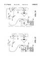
- FIG. 1illustrates a prior art see-through head mounted display system based on lenses and combiners.
- a display 10 and back light 20are mounted with a lens 50 above the user's line of sight. Rays 80 from the display 10 pass through the lens 50 and reflect from the combiner 40 toward the user's eye. Rays 60 from the ambient scene pass through lens 30 and also pass through combiner 40 and are coincident with rays 80 from the display. Thus the user perceives an image comprising the superposition of rays from the display and the ambient scene.
- the lenses in this systemprovide appropriate vergence for the rays so that the image is perceived at the desired depth.
- the size of the various parts in this systemare on the order of 0.5 to 2.0 inches to provide a large exit pupil and require housing and frames that make the system bulky. Additionally, the weight is distributed in such a way as to produce an undesirable torque on the user's head.
- FIG. 2illustrates another prior art head mounted display approach involving a see-around technology.
- a display 10 and backlight 20are mounted with a lens 110 so that rays 100 travel to the eye with appropriate vergence.
- This display systemhaving fewer parts, is somewhat lighter than the see-through display, but it occludes ambient rays. Additionally, both see-around and see-through displays mounted from hats or headbands have a tendency to snag on items in the environment.
- FIG. 3An image source or display 320 and a lens 330 are mounted at the edge of a second "lens" or lens system 300 hereinafter referred to as "main lens” 300.
- Main lens 300is more specifically in the form of an eyeglass lens (with or without vision-correcting optical power) and insert 301, formed for example in the manner of a bifocal insert. It will thus be appreciated that main lens 300 replaces the single lens (or lens system in the case of a bifocal lens) in an eyeglass frame.
- the main lens 300may be more precisely referred to as an optical system comprising embedded lenses and other optical components and surfaces, but is referred to here as main lens 300 for simplicity.
- the term "lens” in general hereinrefers to a surface with optical power and/or to sets of multiple surfaces of optical power, either refractive, diffractive, reflective or otherwise in nature.
- the insert 301 in the main lens 300comprises two materials of different indices of refraction, n 1 and n 2 , with n 1 being greater than n 2 , so that light rays 308 from the image source 320 traveling through the material of higher refractive index and subsequently incident at the interface 302 between the materials are totally internally reflected toward a third lens 340. Ambient light rays 306 pass through the interface 302 and are refracted away from the third lens 340 thus improving contrast of the displayed image.
- the two lenses 330 and 340are chosen such that the combined optical power forms a microscope thus allowing the image from the display to be viewed with the desired magnification.
- an air or other fluid filled gapmay be provided between the materials, or the lower index material may comprise air, another fluid or vacuum, so that if fused silica is used for the main lens 300, the critical angle for total internal reflection will be 43 degrees.
- the angle of the interface 310may be designed for satisfying the condition that the angle of incidence exceed the critical angle for total internal reflection, and also for satisfying the optical requirements for positioning the image to be viewed.
- the optical interface shown hereis planar; however, it may be curved to provide an optical power.
- An alternative embodimentcomprises the use of an insert 301 comprising materials having thin-film interference coatings at the interface to combine the light paths, as is commonly accomplished in dielectric beam splitters and combiners.
- the display 320may comprise a miniature flat panel display, a cathode ray tube or a scanning display as described in U.S. patent application Ser. No. 08/716,103, filed on Sep. 19, 1996, entitled COMPACT DISPLAY SYSTEM, identified by attorney docket No. MOP-101J, assigned to the assignee of the present application and incorporated herein by reference.
- the display 320may be responsive to RF video signals with the RF link being analog or digital depending on particular application requirements and available technology.
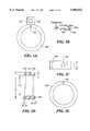
- FIG. 4illustrates another method of forming the image combining system.
- a cube beam splitter 801 used in reverse as a combinerreplaces the totally reflecting surface described earlier.
- the cube beam splitterfor example Edmund Scientific Part A45,111, has the advantage over the totally internally reflecting surface of introducing practically no refraction of ambient rays; however, the cube beam splitter only passes approximately 50% of the ambient and display light to the eye.
- beam splitter 801comprises a polarizing beam splitter
- display 320provides polarized light (such as from a liquid crystal display or laser-scanned display)
- reflection in the range of 75 to 99%may be obtained, depending on wavelength of the display emission and optical design of the coatings in cube 801.
- the cubemay also serve as an analyzer for a liquid crystal display, since it efficiently passes one polarization and not the other.
- a housing 820provides a means to hold two glass or plastic plates 810 that are joined to the cube 801, the plates and other internal parts comprising the main lens 300.
- Light rays from an image sourceare incident through a hole 821 (see FIG. 6) in housing 820.
- Ambient rayspass through one of three paths.
- the first path 830passes through optional polarizing layer 804, through glass 810, through cube 801, through second glass 810, and then to the eye.
- a second path 831passes through optional polarizing layer 804, glass 810, optional polarizing layer 802, second glass 810, and then to the eye.
- the purpose of the optional polarizing layersis to make possible an adjustment of the light level of the ambient scene reaching the eye to provide a balancing of the light level between the display and the ambient scenery, which is made possible by mounting optional polarizer 804 on a rotating bezel 803.
- a third path 832passes through optional polarizing layer 804, glass 810, optional polarizing layer 802, cube 801, and then through second glass 810 to the eye.
- Light passing along path 832will suffer some distortion owing to the off-axis passage through the cube. This effect can be minimized by shaping the beam splitter in a conical form, and by filling the void 806 with a compound optically matched to the cube 801.
- the cube beam splitter 801may be designed and oriented to be sensitive to polarization as previously described, and oriented such that when aligned with the polarizing layer 802, the cube 801 and polarizer 802 absorb equal amounts of rays 830, 832, and 831. If properly aligned, the net transmission of polarized light across the main lens 300 is uniform and the external polarizer 804 may be rotated to adjust the light level of the ambient scene as viewed through the cube or otherwise.
- FIGS. 5A-5E and 6Aillustrate some of the details of the assembly of an eyeglass frame for the device shown in FIG. 4.
- a triangular block 822receives a pipe 823 which houses the optical path from the display, described further below.
- a mirror 824reflects rays on the light path through an angle of 90°, through the opening 821 to the combiner 801.
- the block 822may be mounted to the housing 820 in any suitable manner, for example, by screws 825.
- Two housings 820are assembled to form a pair of eyeglasses, as shown in FIG. 6a.
- the cube 801 in position 301, lens 340 and display 320may also be formed within the main lens 300 as a solid casting, which can then be mounted in conventional eyeglass frames 830, as shown in FIG. 6b.
- FIG. 7shows another embodiment in which the lenses 330 and 340 are replaced by lenses 360 and 370 respectively, which may be glued to the main lens 300 or which may be formed as part of the main lens 300 if for example the lens is injection molded.
- the main lens 300can be formed as a single solid piece by embedding the optical parts in a solid clear or tinted material, such as an optical cement, polycarbonate, epoxy, polymethyl methacrylate, or glass.
- the moldis provided with surfaces that will yield the desired optical power and/or reflections at various places on or within the main lens 300.
- the main lens 300may also be formed from a plurality of cast, molded, or machined parts which are then bonded together to form a solid unit, or alternatively which are mounted in the manner shown in FIGS. 4 to 6.
- a further embodiment of this inventioncomprises the use of an integrated lens 360 with a separate lens 340 or vice versa.
- lenses 330 and 340, or 360 and 370, or any combinationmay comprise achromatic lenses for color correcting dispersion effects in the optical system, or other lens combinations to reduce image aberrations. It should be recognized that lens 360 is optional and may be eliminated in systems requiring simple magnifying optics.
- FIG. 8Another embodiment of the lens system is shown in FIG. 8.
- the lens 360 and display 320are moved to a position behind the main lens 300.
- a reflecting surface 325is provided in the form of a second insert 326 in the main lens 300 for the purpose of directing the incident image to the insert 301.
- Reflecting surface 325may be of the type implemented in the insert 301, which itself may comprise cube 802, or alternatively may be replaced by a mirror mounted internal to the main lens 300 or externally, as shown in FIG. 5A.
- the second insert 326is polarizing, such as in a polarizing beam splitter, the insert 301 or insert 326 may act as the analyzing polarizer (the analyzer) for the case in which the image source 320 is a liquid crystal display.
- the mirrormay be designed to protect the user's eye in the unlikely event that the display regulating system fails.
- the mirror(at surface 325), functioning as an optical fuse, may protect the user from injury by being designed to absorb some of the incident light.
- one or more layers of materials having low thermal conductivitymay be provided beneath the reflective layer of the mirror. With such an arrangement, the light beam may be made to heat the mirror faster than it heats the retina, thereby resulting in damage to the mirror more quickly than to the eye.
- One of the low conductivity layers beneath the mirrormay comprise a material with a high coefficient of thermal expansion which would lead to a bubble or other de-focusing mechanism at the mirror designed to occur at a threshold energy flux below the damage threshold of the retina.
- the image sourcemay also supply infra-red (IR) radiation to enhance this effect.
- IR radiationwould be removed by a filter elsewhere in the system to prevent it from reaching the user's eye.
- the displaymay be back-lit as previously disclosed, or may be illuminated by ambient light rays 401 and/or 402 and/or 403.
- Such a designcan work with the totally internally reflecting insert 326, or with a partially or fully reflecting mirror surface 325, or with a surface with a dielectric coating.
- a fraction of the rays 401, 402, and 403will propagate to the display through the combiner 325. These rays will then be reflected from the display into the optical path leading to the eye.
- the optical systemmay be provided with a condensing or collecting lens to gather and concentrate the rays 401, 402, and 403.
- the rays 401, 402, and 403may be supplied by a lamp mounted optically to the main lens 300 for viewing when insufficient ambient light is available.
- insert 326may comprise a polarizing beam splitter which can act as a polarizer and analyzer for the display.
- This embodimentmay be further improved by adding a crossed rotating system of polarizers as is well known in the art to provide an adjustment in the light level of the ambient scenery. In this way, the light from the display and the ambient scenery light level may be balanced.
- the adjustmentmay be made electronically, and a sensor may be employed for automatic compensation or balance between the relative brightness of the images.
- a further improvement to the designs in the foregoing figurescan be made by adding a fourth lens 410 on the front of the main lens 300 over the insert, as shown in FIG. 9.
- the lens 410being generally of a negative power, counters the positive optical power of the lens 370 so that rays 306 from the ambient scene can be viewed without significant magnification, while rays from the display, which do not pass through lens 410, are viewed with magnification.
- the lens 410may have positive or negative optical power depending on the specific vision correction requirements of the user.
- Other lens surfacesmay be added on either side of the main lens 300 to correct the vision of the user, in the manner of ordinary eyeglasses, and any of the microscope lenses may be adjusted in optical power to correct the user's vision.
- Other lensesmay be added to further correct the vision through lenses 370 and 410. Note also that these lenses may also be incorporated substantially within the volume of the main lens 300.
- the index of refraction n and the radius of curvature of the lensesmust be corrected from their values in air to obtain the desired optical power, within the potting, molding, or machined medium.
- the indices of refraction of the compounds and the lens materialmay be chosen from many compounds having indices in the range of 1.4 to 1.6 for optical polymers or glass, and 1.5 to 2.0 for various other optical materials.
- the optical powermay be developed by providing an air gap or vacuum within the molding material or by materials of low refractive index, with the radius of curvature appropriately designed. Another approach is to fill such a gap with a liquid of high or low refractive index. A further alternative is to employ diffractive or holographic lens elements within the main lens 300.
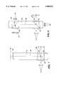
- the imagemay be relayed to the eyeglasses main lens by an image relay 510 which may comprise a coherent optical fiber bundle, or a gradient index (GRIN) lens image conduit, or a relay formed from lenses, illustrated in FIG. 10.
- the image relay 510extends along a side of the eyeglasses, to the display 320.
- the relay 510may be formed with predetermined bends in order to provide the image from the display to a precise location on the main lens 300.
- an additional insert 326 (FIG. 11) in the main lensmay be used to accept the image at the desired angle with the desired optical power and to relay the image to the insert 301, as shown in the embodiments of FIGS. 11 and 12.
- FIG. 11shows an image conduit 510 which relays images from display 320, through fiber optic taper 520 to lens 360.
- the purpose of the fiber optic taperis to match the dimensions of the display to the dimensions of the image conduit.
- the displaymay comprise a miniature flat panel active matrix electroluminescent display having viewable area dimensions of 15.4 mm by 11.5 mm, and the image conduit may have dimensions of 6.4 mm by 6.4 mm (it being desirable to use conduits with as little weight and cross sectional area as possible); the fiber optic taper reduces the image size by a ratio of 2.4:1.
- the image conduit relay 510is positioned within mechanical sleeve 500.
- This sleeveadds strength to the mechanical joint between relay 510 and the eyeglass lens and frame system, and also provides a degree of focus adjustment by permitting the distance between the end surface 511 of relay 510 and the lens 360 to be varied by the user.
- the mechanical sleevemay be fitted with threads, friction locks, or other methods known in the art for precise position adjustments.
- FIG. 12shows another design in which the image relay is fitted with a lens 530 for further modification of the optical power of the imaging system.
- the fiber optic taperis replaced by lens 550 which may have positive or negative power mounted in housing 540 and lens 560 mounted to the image conduit (or alternatively mounted to the housing 540).
- This lens systemaccomplishes the reduction of image size and further makes possible the adjustment of focus through mechanical sleeve 570 in the manner previously described.
- the housing 540may also be provided with means for adjusting the relative positions of the display 320, lenses 550 and 560 and image conduit position.
- the displaymay be joined to the GRIN lens relay by a fiber optic taper 520 or a lens 550, as shown in FIG. 12, or a combination of the two.
- the optical path of the lens systemmay include mirrors 555 so that the path can be folded and thus reduced in volume, while maintaining a long optical pathlength, as in FIG. 13.
- FIG. 14illustrates a plan view of a further lens system incorporated into a pair of eyeglasses.
- This embodimentincludes, on each side, an image relay assembly and a basic two-lens compound microscope (objective and eye lens) for magnifying the image and relaying it to the eye through the combiner.
- Such glassesare capable of displaying binocular stereo imaging.
- the image relay assemblycomprises a display 320 mounted behind the head and a high resolution image relay 510 comprising a GRIN lens image relay which provides an air image near the exit end 511 at a position termed the GRIN image plane.
- the exact position of the GRIN image planedepends upon the position of the focal plane at the entrance end 512 (given by the position of the display).
- the GRIN image planeis 1 to 3 mm from the surface of the GRIN lens.
- the relay 510comprises a coherent fiber bundle
- the image planeis coincident with the end surface 511.
- lenses 360 and 370may comprise systems of lenses.
- the focus of the systemcan be adjusted by moving the display 320 and taper 520 relative to the GRIN lens entrance end 512, by moving the objective lens 360 relative to the GRIN lens image plane (at the exit) and/or by moving the objective lens relative to the eye lens 370.
- the objective lens 360may also be used as a field lens to provide a wide field of view.
- the eye lens 370is moved to a position within the main lens 300. In this position, the eye lens 370 no longer applies an optical power to rays from the ambient scene. Thus, the lens 410 (FIG. 9) is not necessary in this embodiment. Also in this embodiment, when the eyeglasses are in place on the head, the displays remain behind the head. Placing the displays in back of the head has several key advantages compared to conventional forehead-mounted approaches, including improved center of gravity as well as improved cosmetic appeal.
- the imageis provided to the eyes by the GRIN lens image relay, after which the rays are reflected at 90° by a mirror 325 or prism into the main lens 300. The rays pass sideways through the main lens 300 comprising the eye lens 370 and combiner 301.
- the eye lensmagnifies the image from the relay and provides an image plane at a depth at which the user can focus.
- the raysare then reflected by 90° again toward the eye by the combiner, thus providing a virtual image at the desired location in front of the glasses, as shown in FIG. 10.
- the combinerpermits see-through operation by mixing the rays from the relay with ambient rays and comprises a surface coated with dielectric layers to provide 50% transmission over the visible wavelength range.
- the combinercan be replaced by a reflector to make a see-around display with 100% reflection of the displayed image.
- the eyeglassescan be modified for users needing a prescriptive correction by adding curvature to the surfaces of the main lens 300. Other features, such as image capture or eye tracking, can be added to this basic design.
- the diameter of the GRIN lens image relayis less than 3 mm, yet it still provides a transmitted resolution of 200 line pairs per mm (or about 1200 lines).
- Gradient Lens Corporation's EG-27is a 2.61 mm diameter rod capable of relaying an 800 ⁇ 600 image in a rectangle with a 2.5 mm diagonal, which is adequate for relaying a VGA image.
- This high resolution GRIN lens relaywas developed for boroscope and endoscope applications. Since the image is reduced by the fiber optic taper 520 for conveyance to the eyes via the image relay 510, a miniature lens system can be used that permits the adjustment of the collimation distance over a relatively large range, as discussed further below.
- This embodimentis also compatible with prescriptive lenses, which can be bonded to the main lens assembly, and high ambient (see-through) field of view.
- the GRIN and objective lensescan be mounted in a simple mechanical telescoping tubing mount 620 that permits the positions to be varied and provides focus distance adjustment, shown in FIG. 15.
- the GRIN lens 510is mounted within tubing 621 which is frictionally retained but slidable within tubing 622 in which the objective lens 360 is mounted.
- Tubing 622is frictionally retained but slidable within tubing 623 fixed to the main lens 300.
- the tubing mountcan also be threaded (FIG. 5B) to be rotatably adjustable.
- a second adjustmentcan be made by moving the display with respect to the GRIN lens by a similar mechanism. Both adjustments have the effect of changing the collimation distance, discussed further below.
- FIG. 16Ashows another embodiment in which several field lenses 901, 902 are provided within the main lens 300.
- Such field lenseshave the beneficial effect of distributing the optical power, thus reducing the need for high optical power at the eye lens.
- Such lensesalso can serve to increase the field of view.
- These lenses and the other optical partsmay be formed, for example, by the injection molding or machining of multiple parts, followed by coating of the interior surfaces with metal or dielectric layers, and followed further by the assembly of the parts to form the main lens 300 with embedded optical surfaces.
- main lens 300in order to form a main lens 300 well-suited for incorporation in an eyeglass frame, it is desirable to maintain the thickness 934 of the main lens 300 within the range of conventional eyewear (less than 25 mm and preferably in the range of 1 mm to 15 mm).
- the surfaces of main lens 300form an aperture stop in the internal optical path which is of a dimension equal to the thickness 934.
- the partially reflective interface 324also forms a stop. Depending on the magnification of the lenses, these stops may restrict the field of view of the image from the display. This invention overcomes some of the limitations of these stops by using field lenses 901, 902.
- FIG. 16BA second method of overcoming the stop introduced by the main lens 300 thickness 934 is shown in FIG. 16B.
- the interfaces 324, 325are set at angles 455 and 456 less than 45° so that the thickness 934 of the main lens 300 may be reduced.
- the optical pathrequires one or more reflections from the interior surfaces of main lens 300, which occur by total internal reflection as previously discussed. In such a case, embedded lenses 901 are canted appropriately, as shown in the figure.
- lens 410(FIG. 11) may be changed to an opaque disc to convert the see-through system to a see-around system.
- the insert 301may be increased in extent to a large field of view, and the front surface of the main lens 300 may be provided with an opaque cover to form a full immersion system. Any of the opaque covers may be replaced by a liquid crystal shutter that can be electronically adjusted to reduce the light level of the ambient scenery or to block it out entirely Photochromic materials may also be applied to control ambient light.
- a prism or mirrormay be used to form the insert 301.
- Such a deviceis no longer a combiner, but rather is a simple reflector which is all that is needed in a see-around system. This has an advantage over other reflector systems, because the reflecting surface is provided within the main lens 300 and therefore has safety and durability advantages over other approaches.
- a further manner of forming the image combineruses binary optics to form a diffractive optical element having a binary surface structure formed in a surface characterized in the simplest case by an angle 310 (FIG. 3) with respect to the base of the main lens 300.
- the advantage of a diffractive optical elementis that the angle 310 may be made large while still directing light through lens 340, whereas at a reflective surface the angles are fixed by the law of reflection. This permits the field of view through lens 340 to be large, while also permitting the thickness of the main lens 300 to remain relatively small.
- Lens 340 and other lensesmay also comprise diffractive optical elements.
- a disadvantagemay be undesirable wavelength-dependent effects that could be present in a color system.
- the flexibility inherent in the optical design of the complete system described above, such as the ease of insertion of counterbalancing diffractive optical elements elsewhere in the optical pathmakes possible the compensation for chromatic effects, if any.
- the insert 301may be replaced with a holographic combiner by placing a hologram at surface 324 (FIGS. 16A or 16B)
- the combineris designed to work with one or more principal wavelengths emitted by the display.
- the holographic combinercan add optical power and can permit the combiner surface to be placed at a wider range of angles than the reflective combiner.
- the lenses described in the various embodimentsmay be selected to form achromats to remove chromatic aberrations inherent in the various parts of the lens system. It may also be seen that features of the various embodiments may be combined. Additionally, although the figures show singlet lenses, any of the lenses may be replaced by combinations of multiple lenses or surfaces designed to reduce distortion, improve field flatness or add other improvements to the resultant image seen by the user.
- FIG. 17illustrates another application of the lens system that may be used for image acquisition and eye tracking.
- rays 321 from display 320pass through lenses 360, 300, and 370 to the eye, as previously described.
- Rays reflected from the eye 322travel backward along the optical path to the beam splitting interface 325 which directs the light through lens 720 to sensor 710.
- Sensor 710may comprise a CCD or CMOS sensor array as is commonly employed for image acquisition, or an alternate type of image detector.
- the image of the eye thus collectedcan be used to determine the position of the user's eye and in this way the location of the user's gaze.
- Use of eye trackingis advantageous in certain systems for two reasons.
- eye trackingpermits a reduction in the total number of display pixels needed, since, if the location of the fovea is known, a high resolution image need only be displayed in that region. Furthermore, eye tracking can be used to increase the exit pupil of the display. More specifically, the exit pupil of the display can be moved to the optimal location in response to detection of a change in the position of the user's pupil. Eye tracking is also useful for many other applications involving specific system functions.
- the embodiment in FIG. 17also has a provision for collection of imagery from the user's gaze. Rays 395 from the ambient scene are partially reflected by interface 324 along a path represented by ray 775 to a lens 780 and image detector 790.
- the display and sensorsmay operate sequentially if it is necessary to avoid projecting the displayed image into the sensors. It may be seen that many combinations of displays and detectors may be integrated with this system to provide eyeglasses vision correction, display of information, collection of eye tracking imagery, or collection of ambient scenery, including visible and infra-red images.
- a computer screenAs an example of the use of the invention for the formation of a computer display within eyeglasses, consider the creation of a computer screen to be viewed at a distance of 67 cm from the eye. If the height of the desired image is 28 cm, and the image produced at the output 511 of relay 510 is 2.1 mm in height, we require a set of lenses 360 and 370 that produce a magnification of 133. This magnification can be obtained by a lens 360 having, for example, a focal length of 12 mm, and a lens 370 having a focal length of 18 mm. The lens 360 is placed 15.39 mm from the image produced by relay 510. The lens 370 is placed 72 mm distant from the lens 360. This produces a virtual image 67 mm distant from the eye.
- the raysare divergent.
- the imagecan be formed at infinity or elsewhere depending on the relative position of the lenses. This calculation has been made for the case in which the space between the lenses comprises air. If a material of index n>1 is used, for example, in a solid embodiment of the main lens 300, the distances are adjusted accordingly.
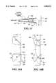
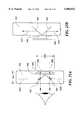
- FIG. 18shows a prior art catadioptric design based on a free space combiner in which the image generated by the display 901 is reflected by a plane partially-transmissive mirror or dielectric coated surface 920 toward a curved mirror or coated reflecting element 900 which reflects the light back toward the eye.
- the element 900has curvature, the vergence of the light reflected from it is changed, which permits the eye to perceive a virtual image in space at a comfortable distance in front of the eye.
- This element 900serves the same function optically as the lens 370 in FIG. 8.
- Light passing through the element 900, such as rays 910 from the ambient scenepasses without any change in its vergence.
- the scene as depicted by rays 910can be viewed unimpeded in vergence by the optical power of the display viewing optics.
- the element 900does introduce absorption and therefore the rays 910 having passed surface 900 are attenuated.
- the element 900is reduced in size and brought within the main lens 300.
- the combiner 920may comprise a half-silvered mirror or beam splitter cube as previously described, or it may comprise a polarizing beam splitter.
- a polarizing beam splitterFor the case of a polarizing beam splitter, a large fraction of light which is polarized in the proper axis is reflected toward the element 900.
- a rotation of the axisis effected so that the ray passes efficiently through the polarizing beam splitter to the eye.
- Optical coatings known in the art of interference filtersmay be used on the combiner 920 and on the element 900 to yield efficient passage of ambient rays and display imagery.
- the optical coatingsmay be configured for high reflectivity for these narrow wavelength ranges at the surface of element 900, while rays 910 passing through the element are impeded only in these narrow ranges and thus the image is seen largely free of color distortion.
- FIG. 19Bshows an alternate embodiment of the same nature, with polarizations and element 900 oriented so that rays 910 are unimpeded by mirror 900.
- Prior art head mounted displaysare limited to a single collimation distance (the distance at which the image is perceived based on focus). Often in stereo head mounted displays, this distance is in conflict with the distance perceived from the vergence of the eyes.
- the inventionovercomes this problem by permitting the display of multiple images at different collimation distances.
- a multiple collimation distance displayfuses the images from two or more display sources to provide the user with background and foreground images at different focal distances.
- xthere are three displays at three distinct distances from the GRIN lens, leading to three values of x and three values of y, one for each display. If x is adjusted by a small amount, the collimation distance is changed by a large amount.
- the table belowshows a calculation of collimation distance as a function of distance from the objective for one optical design.
- This tableshows that a change of 186 ⁇ m in the distance between the image and the objective lens yields a change in collimation distance of from 12.7 cm to 254M (essentially infinity), for the particular optical design for which the calculation was made.
- a combiner cube 945as is commonly done when joining red, green, and blue images in LCD projectors
- the displaysare set at different distances (illustrated as 0 mm, t, and u in FIG. 20) from the GRIN image relay, the user will have to focus in different planes to see the images (just as the eye does when viewing real images), as shown in FIG. 20.
- the differences in distancecan be obtained by interposing thin layers of glass between the cube and the displays.
- the image generatedcan now have three separate simultaneous planes corresponding to foreground, mid, and background. This effectively removes the problem of collimation distance and eye vergence disparity from the hardware.
- a dithering mechanismmoves the objective lens to the desired position.
- Such an approachcould be synchronized with a flat panel display running at 180 frames per second to provide three separate image planes. Note that the required lens translation was shown earlier to be only 186 ⁇ m.
- Another approachcomprises stacking in the manner of FIG. 21, which has been used for subtractive color LCDs.
- three displays 955are stacked and each display removes one color from the final image.
- the displaysmay be separated by polarizers 956.
- color displayscan be used to provide an image characterized by multiple image planes at various collimation depths, depending on the spacing of the displays.
- the variation in collimation distance between planesis considered a detrimental artifact.
- the variation in collimation depthcan be used to provide an improved image.
- a further advantagemay be possible by using a low resolution display for the background, to reduce system cost.
- the adjustable collimation distancemay be attained in several ways.
- the firstcomprises the use of several pixels at different distances from the entrance pupil of the beam scanning system. This approach can be attained by using several optical fibers each of which is displaced from the entrance pupil by a fixed different amount, leading to a different collimation distance for each fiber.
- the photons intended to be displayedare then routed over the fiber corresponding to the desired collimation distance.
- a second methodcomprises the use of micro-mechanical mirrors to adjust the path length from a single fiber to the objective.
- the collimation distancecan be set for each pixel.
- the optical distancemay be adjusted by passing the light rays through a medium having an index of refraction that can be altered by an external force.
- FIG. 22shows an example of the integration of the optical system 870, a face mask structure 872, and computer circuits 874 to form a completely integrated computer within a face mask system.
- the face maskprovides sufficient area at the edge for integrated circuit mounting.
- the displaycan be mounted directly to the edge of the lens, as indicated in FIG. 22.
- circuitry and displayscan also be potted within the face mask at its edge to yield hermetic protection from water.
- FIG. 22shows two displays, which allow generation of a stereo image.
- the combinerscan be located directly within the ordinary field of view or can be located out of the ordinary field of view (as shown) such that, to see the display, the user must look up, down, or to the side, to wherever the optical system has been placed.
- Suitable displays for a face maskare active matrix electroluminescent displays or active matrix liquid crystal displays, which are commercially available.
- a beam scanning devicethat creates a highly miniaturized image plane on a surface that by use of lenses and folded, embedded optics as previously described, is directed to the user's eye.
- the image planeis formed by scanning the light from an optical fiber over the points defining the miniaturized plane 978. Since this scanned pixel can comprise a diffraction-limited spot, the image plane can be extremely small.
- the scanned pixelis synchronized with grey-level and/or color data delivered over the fiber, so that each point on the miniature image plane is painted with the appropriate photon stream, to produce the desired image at the screen.
- the optical data delivered to the scanner by fiberis generated within a computer and so the graphics circuit must drive a set of optical sources (such as lasers) that produce the desired combination of red, green and blue, at the desired intensity.
- the beam scannercan be formed by micro-electromechanical silicon machining (MEMS).
- MEMSmicro-electromechanical silicon machining
- the most direct way to form the scanning systemis by fabricating horizontal and vertical mirrors 970, 971 that are used to steer the photons to the desired point, as shown in FIG. 23.
- the vertical and horizontal scanning mirrorsare formed in close proximity to limit complexity of the relay optics.
- the vertical scanning mirror 971can oscillate at 60 Hz for conventional frame rates.
- a micromachined wave guidemay also be fabricated.
- a beam steering devicecan be formed with optical fibers.
- the difficulty with such devicesis that one is constrained to the mechanical properties of the available optical fiber.
- an advantage of a micromachined scanner according to the present inventionis that thin films may be used to tailor the mechanical resonant frequencies and waveguide geometries in designs that may be unattainable with fused silica fibers.
- the MEMS-based scanner described aboveis also operable as an image collection device.
- the imaging opticscan be used to transmit a return image of the eye that can be used for eye tracking.
- the display opticsincluding the scanning system, can be used for both the display of the image and the collection of an image of the eye, which can be returned from the system to a detector, as indicated in FIG. 23.
- the delivery of photons to the eyehas a reciprocal optical process, in which axial reflections from the retina return along the same optical path, if the system is in axial alignment.
- the strength of the return signalcan be increased in a number of ways.
- red, green, and blue wavelengthsmay be combined along the optical path to form a color display.
- infrared (IR) wavelengthsmay be added as a fourth band that is not perceived by the user. In this way, an infrared pattern may be painted in the eye, and by detection of the returned pattern, the position of the eye may be determined.
- FIG. 23illustrates how such a device operates. Visible and IR light rays are transmitted synchronously to the scanning mirrors 970, 971 to project an image into the eyeglasses optical system, and from there into the eye. If the eye is at the exit pupil in correct alignment, a return signal is reflected into the optical path. The return (reflected) signal propagates to the coupler 972 and from there to the detector 974. If the illumination light is constant (blank screen), then the reflected stream of pixels is in fact a pixelated image of the eye which can be reformed by the computer 976 into an image of the eye. If however, the illumination light is an image itself, then the reflected stream of pixels comprises a convolution of the original image and the reflected image.
- the computercan deconvolve the images (since the image sent to the eye is known) and create an image of the eye.
- Another methodis to use modulated visible light for the image sent to the eye, and constant IR to illuminate the eye so as to create a return IR image. All of these methods result in the creation of an image of the retina from which the direction of gaze can be determined.
- the system shown in FIG. 23can also be used with a standard flat panel approach to eyeglasses or head mounted display design, as shown in FIG. 24.
- the MEMS systemcollects an image of the eye only and is not used to form the display image.
- the display imageis provided through a combiner by a flat panel display.
- FIGS. 25A and 25Bshow a further embodiment in which the field of view can be increased without substantially increasing the thickness 934 of the main lens 300.
- the field of viewis increased by attaining an increase in the width 1003 of the aperture stop introduced by the combiner interfaces (324 in FIG. 16), as previously described.
- FIG. 25Ashows the use of two combining interfaces, 922, 921 which receive light from opposite optical paths 1001 and 1002. Note that a single interface and single path were shown in the catadioptric approach illustrated in FIG. 19; this embodiment uses two such paths combined to provide a doubling in the size of the aperture stop 1003.
- FIG. 25Billustrates how light is divided up into two paths 1001 and 1002.
- the display 320 and lens 360provide rays to reflective interfaces 923, 924, thus splitting the rays into the two paths 1001 and 1002 in a manner symmetric with the recombining interfaces 921, 922.
- FIG. 26illustrates in plan view the main lens 300. Light enters the main lens 300 and is reflected by interfaces 923, 924 along the two paths.
- Four embedded mirrors 925 within the main lens 300reflect the light to surfaces 921, 922.
- the embedded mirrors 925are formed with their reflective interfaces approximately orthogonal to the surfaces of the main lens 300 and therefore approximately parallel to rays from the ambient scene transmitted through the main lens 300 to the user's eye.
- mirrors 925have minimal effect on sight through the main lens 300.
- the interfaces 921, 922, 923, 924may comprise dielectric coatings designed to reflect the particular range of wavelengths emitted by the display 320, and not others, and in this way stray reflections within the main lens 300 may be reduced.
- FIGS. 25A and 25Bcomprises a combiner formed from two perpendicular surfaces 921 and 922 formed from the sides of a right angle prism. Rays 1001 from the top and rays 1002 from the bottom combine with external rays 306 as previously described to form the image, thus doubling the maximum field of view of the displayed image, without increasing the thickness of the main lens 300. In this way, the height 1003 of the combiner can be made twice the thickness of the main lens 300 while still preserving the required angles, which for a beam splitter cube are 450 angles. In this embodiment, the image must be provided to the combining system from two paths, as shown in plan view in FIG. 26.
- the rays that form the imageenter the main lens 300 through the surfaces 923 and 924, which are also configured to form perpendicular surfaces. These surfaces split the incoming rays into two paths. Rays entering through the lower surface 923 take the path indicated by ray 1002. Rays entering through the upper surface take the path indicated by ray 1001. Four mirrors 925 fold the optical path so that the entire arrangement may be placed within the main lens 300. These examples show the use of this mirror system with catadioptric lenses, but the other embodiments discussed previously can also be used.
- a further improvementcan be made by locating image planes in the optical design so as not to occur upon a plane that includes the vertex of the surfaces 921 and 922 and the vertex of the surfaces 923 and 924. In this way, artifacts in the final image resulting from the splitting of the rays can be minimized.
- One method to accomplish thisis to place the lenses needed in the optical system (such as 360 and 370, for example, or mirror 900) near these surfaces so as to form images in other planes.
- This inventionis not limited to square combiners and no limitation in combiner width 1004 is imposed by any of the foregoing improvements.
- the aspect ratio of the field of viewmay be altered simply by widening the interfaces 920 and 921 as needed.
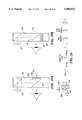
- FIG. 27shows an embodiment in which the field of view of rays emanating from the optical relay 510 is increased by insertion of an optical element 515 comprising, for example, a diffusing screen, a microlens array, a fiberoptic faceplate, or a diffractive optical element.
- the element 515is positioned with respect to the surface 511 to coincide with an image plane, so as to form an image on the element 515.
- the element 515may be bonded directly to the end surface 511 or etched into the end surface.
- the relay 510is a GRIN image relay
- the element 515is placed at the location of the image produced by the relay 510.
- the element 515is placed at a focal plane of the lens system. In this way, the element 515 increases the field of view of the pixels by one or more of the mechanisms of diffusion, refraction, or diffraction as the case may be for the type of element or combinations used. The result of using such a screen is an increase in the field of view in the image as seen by the user.
- optical element 515is a fiberoptic faceplate
- one or both surfaces of the faceplatemay be curved to improve field-flatness of the displayed image.
- Eyeglasses displayshave been built in accordance with the invention described herein, indicated in FIGS. 28A and 28B.
- the main lens 300is housed in a commercial eyeglass frame 830.
- the main lens 300comprises an embedded polarizing beam splitting cube 801 and an embedded prism 1100 which serve to reflect light from the active matrix liquid crystal display 320.
- the displayis lit by backlight 1103 and the display and light are contained in housing 1105.
- the displayis connected electrically to electronic circuits (not shown in FIGS. 28A or 28B).
- the display 320is mounted optically to spacer 1101 so that the index of refraction of the medium between the display and the surface of lens 370 is relatively well-matched to minimize internal reflections, the indices of refraction of the materials being in the range of 1.4 to 1.6.
- the display 320is positioned so that the polarization of light emitted by the display is in a favorable direction for reflection by cube 801 toward the eye, with minimal transmission through the cube's interface.
- Lens 370a singlet plano-convex lens having a positive power, reduces the vergence of rays from the cube 801, thus enabling the user to perceive a virtual image at approximately 50 cm.
- Lens 410a singlet plano-concave lens having a negative power, precorrects light from the ambient scene so that in combination lenses 370 and 410 transmit light relatively free of vergence change.
- the optimized selection of the relative power and spacing of lenses 410 and 370, and/or the use of multiple lenses (doublets for example) as provided for in this invention,will yield reduced overall distortion of the ambient image as seen through the cube.
- the overall thickness of the main lens 300 (934 in FIG. 16A) in this embodimentis 6.25 mm.
- FIG. 29illustrates a method of packaging a flat backlight 1110, display 320 and prism 1111 within the temple 1112 of eyeglasses to conceal the display.
- the lenses 370 and 410, or other opticscan be embedded within the main lens 300 as shown in FIG. 29 or as previously described herein. Sensors and lenses (i.e. a camera system) can be added, as can an eyetracking system, both of which have been previously described herein.
- the appearance of the main lens 300is similar to a bifocal lens.
- FIG. 29shows a monocular system; however, two main lenses 300, left and right, may be employed for a binocular system. Also, the left main lens 300 may house the display system, while the right main lens 300 may house a sensor system. The presence of embedded optics can be further disguised by using polarizing, photochromic, tinted, or reflective films in the manner of sunglasses. The result is an eyeglasses display system having the aesthetic appeal of conventional eyewear, with no display, camera, or eyetracker evident upon casual inspection.
Landscapes
- Physics & Mathematics (AREA)
- General Physics & Mathematics (AREA)
- Optics & Photonics (AREA)
- Spectroscopy & Molecular Physics (AREA)
- Studio Devices (AREA)
- Image Processing (AREA)
- Lenses (AREA)
Abstract
Description
______________________________________Distance from Display Collimation DistanceImage to Objective (mm) (mm)______________________________________15.245 127.915.280 163.815.315 221.315.350 328.515.385 598.415.420 2568.615.425 4691.615.431 254887.8______________________________________
Claims (114)
Priority Applications (10)
| Application Number | Priority Date | Filing Date | Title |
|---|---|---|---|
| US08/844,098US5886822A (en) | 1996-10-08 | 1997-04-18 | Image combining system for eyeglasses and face masks |
| CA002268196ACA2268196C (en) | 1996-10-08 | 1997-10-02 | Image combining system for eyeglasses and face masks |
| PCT/US1997/017620WO1998015868A1 (en) | 1996-10-08 | 1997-10-02 | Image combining system for eyeglasses and face masks |
| EP07106671AEP1808722A3 (en) | 1996-10-08 | 1997-10-02 | Image Combining System for Eyeglasses and Face Masks |
| EP97913664AEP1012655B1 (en) | 1996-10-08 | 1997-10-02 | Image combining system for eyeglasses and face masks |
| DE69737700TDE69737700T2 (en) | 1996-10-08 | 1997-10-02 | PICTURE COMBINING DEVICE FOR EYES AND FACIAL MASKS |
| JP51758998AJP3429320B2 (en) | 1996-10-08 | 1997-10-02 | Image combining system for eyeglasses and face mask |
| US09/271,597US6204974B1 (en) | 1996-10-08 | 1999-03-17 | Compact image display system for eyeglasses or other head-borne frames |
| US09/652,629US6356392B1 (en) | 1996-10-08 | 2000-08-31 | Compact image display system for eyeglasses or other head-borne frames |
| US09/653,751US6384982B1 (en) | 1996-10-08 | 2000-09-01 | Compact image display system for eyeglasses or other head-borne frames |
Applications Claiming Priority (2)
| Application Number | Priority Date | Filing Date | Title |
|---|---|---|---|
| US2799896P | 1996-10-08 | 1996-10-08 | |
| US08/844,098US5886822A (en) | 1996-10-08 | 1997-04-18 | Image combining system for eyeglasses and face masks |
Related Parent Applications (1)
| Application Number | Title | Priority Date | Filing Date |
|---|---|---|---|
| US09/170,887Continuation-In-PartUS6023372A (en) | 1996-10-08 | 1998-10-14 | Light weight, compact remountable electronic display device for eyeglasses or other head-borne eyewear frames |
Related Child Applications (2)
| Application Number | Title | Priority Date | Filing Date |
|---|---|---|---|
| US09/170,887Continuation-In-PartUS6023372A (en) | 1996-10-08 | 1998-10-14 | Light weight, compact remountable electronic display device for eyeglasses or other head-borne eyewear frames |
| US09/271,597Continuation-In-PartUS6204974B1 (en) | 1996-10-08 | 1999-03-17 | Compact image display system for eyeglasses or other head-borne frames |
Publications (1)
| Publication Number | Publication Date |
|---|---|
| US5886822Atrue US5886822A (en) | 1999-03-23 |
Family
ID=26703139
Family Applications (1)
| Application Number | Title | Priority Date | Filing Date |
|---|---|---|---|
| US08/844,098Expired - LifetimeUS5886822A (en) | 1996-10-08 | 1997-04-18 | Image combining system for eyeglasses and face masks |
Country Status (6)
| Country | Link |
|---|---|
| US (1) | US5886822A (en) |
| EP (1) | EP1012655B1 (en) |
| JP (1) | JP3429320B2 (en) |
| CA (1) | CA2268196C (en) |
| DE (1) | DE69737700T2 (en) |
| WO (1) | WO1998015868A1 (en) |
Cited By (487)
| Publication number | Priority date | Publication date | Assignee | Title |
|---|---|---|---|---|
| US6005720A (en)* | 1998-12-22 | 1999-12-21 | Virtual Vision, Inc. | Reflective micro-display system |
| US6023372A (en)* | 1997-10-30 | 2000-02-08 | The Microoptical Corporation | Light weight, compact remountable electronic display device for eyeglasses or other head-borne eyewear frames |
| US6057966A (en)* | 1997-05-09 | 2000-05-02 | Via, Inc. | Body-carryable display devices and systems using E.G. coherent fiber optic conduit |
| US6088154A (en)* | 1997-04-03 | 2000-07-11 | Olympus Optical Co., Ltd. | Operating microscope |
| US6091546A (en)* | 1997-10-30 | 2000-07-18 | The Microoptical Corporation | Eyeglass interface system |
| US6141440A (en)* | 1998-06-04 | 2000-10-31 | Canon Kabushiki Kaisha | Disparity measurement with variably sized interrogation regions |
| JP2000352689A (en)* | 1999-06-11 | 2000-12-19 | Minolta Co Ltd | Video display device |
| JP2001066544A (en)* | 1999-08-31 | 2001-03-16 | Minolta Co Ltd | Video display device |
| US6243054B1 (en) | 1998-07-01 | 2001-06-05 | Deluca Michael | Stereoscopic user interface method and apparatus |
| US6301050B1 (en)* | 1999-10-13 | 2001-10-09 | Optics Wireless Led, Inc. | Image enhancement system for scaled viewing at night or under other vision impaired conditions |
| US20010033401A1 (en)* | 2000-03-17 | 2001-10-25 | Minolta Co., Ltd. | Information display device |
| US6312129B1 (en)* | 1998-07-21 | 2001-11-06 | L-3 Communications Corp. | Head mounted projector system |
| US6333820B1 (en)* | 1997-06-27 | 2001-12-25 | Olympus Optical Co., Ltd. | Image display apparatus |
| US20020008675A1 (en)* | 2000-06-14 | 2002-01-24 | Theodore Mayer | Method and apparatus for seamless integration of images using a transmissive/reflective mirror |
| JP2002031777A (en)* | 2000-05-11 | 2002-01-31 | Nikon Corp | Electronic glasses |
| US20020021407A1 (en)* | 2000-08-01 | 2002-02-21 | Scott Elliott | Eye-wear video game |
| US6352347B1 (en)* | 1999-01-28 | 2002-03-05 | Norman P. Unema | Viewing direction modifying device and method |
| US6353503B1 (en) | 1999-06-21 | 2002-03-05 | The Micropitical Corporation | Eyeglass display lens system employing off-axis optical design |
| US6356392B1 (en) | 1996-10-08 | 2002-03-12 | The Microoptical Corporation | Compact image display system for eyeglasses or other head-borne frames |
| US20020044152A1 (en)* | 2000-10-16 | 2002-04-18 | Abbott Kenneth H. | Dynamic integration of computer generated and real world images |
| US6404557B2 (en) | 1999-09-10 | 2002-06-11 | Inviso, Inc. | Display illumination system |
| US6417969B1 (en) | 1988-07-01 | 2002-07-09 | Deluca Michael | Multiple viewer headset display apparatus and method with second person icon display |
| EP1196809A4 (en)* | 1999-06-21 | 2002-08-28 | Microoptical Corp | Display device with eyepiece assembly and display on opto-mechanical support |
| US6456260B1 (en)* | 1997-11-21 | 2002-09-24 | Robert Bosch Gmbh | Indicating device for vehicle |
| US20020143284A1 (en)* | 2001-04-03 | 2002-10-03 | Hosheng Tu | Drug-releasing trabecular implant for glaucoma treatment |
| US6474809B2 (en) | 2000-09-11 | 2002-11-05 | Minolta Co., Ltd. | Image display apparatus |
| US6480337B2 (en)* | 1999-03-04 | 2002-11-12 | Mixed Reality Systems Laboratory Inc. | Image display apparatus |
| US6487021B1 (en)* | 1999-06-22 | 2002-11-26 | Koninklijke Philips Electronics N.V. | Head-mounted display |
| US20020176173A1 (en)* | 2001-04-30 | 2002-11-28 | Song Young-Ran | Wearable display system and process thereof |
| US20020191254A1 (en)* | 2001-06-19 | 2002-12-19 | Robert Mays | Network routing employing free-space optical broadcasting |
| US20020191598A1 (en)* | 2001-06-19 | 2002-12-19 | Robert Mays | Network switch employing free-space optical switching technique |
| US20030057577A1 (en)* | 2001-08-14 | 2003-03-27 | Odile Primel | Process for moulding a lens having an insert |
| US20030060752A1 (en)* | 2000-04-14 | 2003-03-27 | Olav Bergheim | Glaucoma device and methods thereof |
| US20030058543A1 (en)* | 2001-02-21 | 2003-03-27 | Sheedy James B. | Optically corrective lenses for a head-mounted computer display |
| US6542307B2 (en) | 2000-10-20 | 2003-04-01 | Three-Five Systems, Inc. | Compact near-eye illumination system |
| US20030068057A1 (en)* | 2001-10-06 | 2003-04-10 | Miller Eric C. | Information system using eyewear for communication |
| US6563648B2 (en) | 2000-10-20 | 2003-05-13 | Three-Five Systems, Inc. | Compact wide field of view imaging system |
| US20030090439A1 (en)* | 2001-09-07 | 2003-05-15 | Spitzer Mark B. | Light weight, compact, remountable face-supported electronic display |
| US20030097151A1 (en)* | 2001-10-25 | 2003-05-22 | Smedley Gregory T. | Apparatus and mitochondrial treatment for glaucoma |
| US20030115010A1 (en)* | 2000-06-23 | 2003-06-19 | Estep Randall S. | Process for the production of epothiolone b and derivatives as well as intermediate products for this process |
| US6584235B1 (en)* | 1998-04-23 | 2003-06-24 | Micron Technology, Inc. | Wide dynamic range fusion using memory look-up |
| FR2834078A1 (en)* | 2001-12-21 | 2003-06-27 | Voxel Electronics Ind | Real image formation optical apparatus for direct vision having image source crossing partially reflected inclined mirror and concave mirror forming real image from image source |
| WO2003058320A1 (en)* | 2002-01-11 | 2003-07-17 | Essilor International (Compagnie Générale d'Optique) | Ophthalmic lens with a projection insert |
| US6600460B1 (en)* | 1998-08-25 | 2003-07-29 | R&Dm Foundation | Miniature projector |
| US6603443B1 (en)* | 1994-12-21 | 2003-08-05 | Three-Five Systems, Inc. | Compact display system controlled by eye position sensory system |
| GB2386699A (en)* | 2001-04-30 | 2003-09-24 | Samsung Electronics Co Ltd | Head Mounted Display with Prism and Cut Waveguide |
| US20030187385A1 (en)* | 2000-04-14 | 2003-10-02 | Bergheim Olav B. | Implant with anchor |
| US6636359B2 (en)* | 2000-06-08 | 2003-10-21 | Interactive Imaging Systems, Inc. | Two stage optical magnification and image correction system |
| EP1132870A3 (en)* | 2000-03-07 | 2003-10-29 | Agilent Technologies, Inc. (a Delaware corporation) | Personal viewing device with system for providing identification information to a connected system |
| US20040004767A1 (en)* | 2002-05-13 | 2004-01-08 | Samsung Electronics Co., Ltd. | Wearable display system adjusting magnification of an image |
| US20040012758A1 (en)* | 2002-07-19 | 2004-01-22 | Chao-Chyun Lin | Prism based dynamic vision training device and method thereof |
| US20040024345A1 (en)* | 2002-04-19 | 2004-02-05 | Morteza Gharib | Glaucoma implant with valveless flow bias |
| US20040042200A1 (en)* | 1998-11-23 | 2004-03-04 | Hurwitz Marni M. | Marine craft and apparatus including electroluminescent auxiliary illumination |
| EP1405125A1 (en)* | 2001-07-06 | 2004-04-07 | Carl Zeiss | Head-mounted optical direct visualisation system |
| US6724354B1 (en) | 1999-06-21 | 2004-04-20 | The Microoptical Corporation | Illumination systems for eyeglass and facemask display systems |
| US20040094700A1 (en)* | 2000-12-29 | 2004-05-20 | Danny Filipovich | Image enhancement system and method for night goggles |
| US20040102729A1 (en)* | 2002-04-08 | 2004-05-27 | David Haffner | Devices and methods for glaucoma treatment |
| US20040111050A1 (en)* | 2000-04-14 | 2004-06-10 | Gregory Smedley | Implantable ocular pump to reduce intraocular pressure |
| US20040127843A1 (en)* | 2000-04-14 | 2004-07-01 | Hosheng Tu | Glaucoma implant with therapeutic agents |
| US20040147870A1 (en)* | 2002-04-08 | 2004-07-29 | Burns Thomas W. | Glaucoma treatment kit |
| US20040156012A1 (en)* | 2002-07-26 | 2004-08-12 | James Jannard | Electronic eyewear with hands-free operation |
| US20040156114A1 (en)* | 2003-01-03 | 2004-08-12 | Sayed Atika El | Facial mounting equipped with a lateral device for diffusion of virtual images towards a user's pupil |
| US20040160573A1 (en)* | 2000-06-02 | 2004-08-19 | James Jannard | Wireless interactive headset |
| US20040165284A1 (en)* | 2003-02-17 | 2004-08-26 | Frank Holler | Display device with electrooptical focussing |
| US20040183751A1 (en)* | 2001-10-19 | 2004-09-23 | Dempski Kelly L | Industrial augmented reality |
| US20040212776A1 (en)* | 2003-04-25 | 2004-10-28 | Spitzer Mark B. | Binocular viewing system |
| US6816314B2 (en) | 2000-09-11 | 2004-11-09 | Minolta Co., Ltd. | Head-mounted image display apparatus |
| US20050012683A1 (en)* | 2003-07-15 | 2005-01-20 | Yu-Yu Chen | Spectacle with data receiving and projecting device |
| US6853812B2 (en) | 2001-05-09 | 2005-02-08 | Robert Mays, Jr. | Polarized-holographic filtering providing improved extinction ratio |
| US20050046953A1 (en)* | 2003-08-29 | 2005-03-03 | C.R.F. Societa Consortile Per Azioni | Virtual display device for a vehicle instrument panel |
| US20050049578A1 (en)* | 2000-04-14 | 2005-03-03 | Hosheng Tu | Implantable ocular pump to reduce intraocular pressure |
| US20050090807A1 (en)* | 1999-04-26 | 2005-04-28 | Gmp Vision Solutions, Inc. | Shunt device and method for treating glaucoma |
| US20050119636A1 (en)* | 2001-05-02 | 2005-06-02 | David Haffner | Implant with intraocular pressure sensor for glaucoma treatment |
| US6903875B2 (en) | 2003-09-03 | 2005-06-07 | Carl-Zeiss Ag | HMD device with imaging optics comprising an aspheric surface |
| US20050192527A1 (en)* | 2001-05-02 | 2005-09-01 | Morteza Gharib | Glaucoma implant with extending members |
| WO2005085933A1 (en)* | 2004-03-08 | 2005-09-15 | Sony Corporation | Image display device |
| US20050231419A1 (en)* | 2004-04-15 | 2005-10-20 | Lockheed Martin Ms2 | Augmented reality traffic control center |
| US20050250788A1 (en)* | 2004-01-30 | 2005-11-10 | Hosheng Tu | Aqueous outflow enhancement with vasodilated aqueous cavity |
| US20050266047A1 (en)* | 2002-04-08 | 2005-12-01 | Hosheng Tu | Injectable glaucoma implants with multiple openings |
| US20050271704A1 (en)* | 2002-04-08 | 2005-12-08 | Hosheng Tu | Injectable glaucoma implants with multiple openings |
| US20050277864A1 (en)* | 2000-04-14 | 2005-12-15 | David Haffner | Injectable gel implant for glaucoma treatment |
| FR2872586A1 (en)* | 2004-07-02 | 2006-01-06 | Essilor Int | OPHTHALMIC DISPLAY HAVING A FOCUSING ADJUSTMENT DEVICE |
| US20060023160A1 (en)* | 2004-08-02 | 2006-02-02 | Cartier Jon P | Lens structure and method of making the same |
| US20060055786A1 (en)* | 2004-03-09 | 2006-03-16 | Viosport | Portable camera and wiring harness |
| US20060072067A1 (en)* | 2000-06-02 | 2006-04-06 | Jannard James H | Eyeglass with MP3 player |
| US7082267B1 (en) | 2000-08-25 | 2006-07-25 | R& Dm Foundation | Shared multi-channel parallel optical interface |
| US7099590B2 (en) | 2000-08-25 | 2006-08-29 | R&Dm Foundation | Filtering technique for free space interconnects |
| US20060192306A1 (en)* | 2005-02-25 | 2006-08-31 | The Microoptical Corporation | Manufacturing methods for embedded optical system |
| US20060192307A1 (en)* | 2005-02-25 | 2006-08-31 | Eugene Giller | Method for producing high quality optical parts by casting |
| US7116491B1 (en)* | 2005-08-19 | 2006-10-03 | Itt Manufacturing Enterprises, Inc. | Ganged focus mechanism for an optical device |
| US20060236121A1 (en)* | 2005-04-14 | 2006-10-19 | Ibm Corporation | Method and apparatus for highly secure communication |
| US20060236120A1 (en)* | 2005-04-14 | 2006-10-19 | Ibm Corporation | Method and apparatus employing stress detection for highly secure communication |
| US20060241749A1 (en)* | 2001-08-28 | 2006-10-26 | Hosheng Tu | Glaucoma stent system |
| WO2006114536A1 (en)* | 2005-04-28 | 2006-11-02 | Essilor International, Cie Generale D'optique | Ophthalmic display |
| US7158096B1 (en) | 1999-06-21 | 2007-01-02 | The Microoptical Corporation | Compact, head-mountable display device with suspended eyepiece assembly |
| US7170677B1 (en) | 2002-01-25 | 2007-01-30 | Everest Vit | Stereo-measurement borescope with 3-D viewing |
| US20070047091A1 (en)* | 2005-03-22 | 2007-03-01 | The Microoptical Corporaiton | Optical system using total internal reflection images |
| US7186232B1 (en) | 2002-03-07 | 2007-03-06 | Glaukoa Corporation | Fluid infusion methods for glaucoma treatment |
| US20070112292A1 (en)* | 2001-04-07 | 2007-05-17 | Hosheng Tu | Glaucoma stent and methods thereof for glaucoma treatment |
| WO2007031986A3 (en)* | 2005-09-12 | 2007-05-31 | Elbit Systems Ltd | Near eye display system |
| US20070153395A1 (en)* | 2005-12-29 | 2007-07-05 | C.R.F. Societa Conrostile Per Azioni | Optical system for image transmission, particularly for projection devices of the head-mounted type |
| USD547346S1 (en) | 2004-03-09 | 2007-07-24 | V.I.O., Inc. | Camera |
| US20070236800A1 (en)* | 2006-03-03 | 2007-10-11 | Ozan Cakmakci | Imaging systems for eyeglass-based display devices |
| US20070284768A1 (en)* | 2004-12-22 | 2007-12-13 | Nobuaki Takahashi | Manufacturing Method Of Lens With Built-In Hologram Element |
| US20070285752A1 (en)* | 2004-06-29 | 2007-12-13 | Nikon Corporation | Image Combiner and Image Display Device |
| US20070293807A1 (en)* | 2006-05-01 | 2007-12-20 | Lynch Mary G | Dual drainage pathway shunt device and method for treating glaucoma |
| US20080015488A1 (en)* | 2001-05-03 | 2008-01-17 | Glaukos Corporation | Glaucoma implant with double anchor mechanism |
| US20080024391A1 (en)* | 2006-07-31 | 2008-01-31 | Manuel Oliver | Image alignment method for binocular eyewear displays |
| US20080064326A1 (en)* | 2006-08-24 | 2008-03-13 | Stephen Joseph Foster | Systems and Methods for Casting Captions Associated With A Media Stream To A User |
| US20080136742A1 (en)* | 1998-08-05 | 2008-06-12 | Microvision, Inc. | Method and Apparatus for Compensating for Distortion in a Scanned Beam System |
| US20080172204A1 (en)* | 2007-01-15 | 2008-07-17 | Fujitsu Limited | Step counter and method of counting steps |
| CN100416340C (en)* | 2003-04-25 | 2008-09-03 | 微型光学公司 | binocular viewing system |
| US7461936B2 (en) | 2000-06-02 | 2008-12-09 | Oakley, Inc. | Eyeglasses with detachable adjustable electronics module |
| WO2008083170A3 (en)* | 2007-01-02 | 2008-12-18 | Hind Sight Ind Inc | Eyeglasses with integrated telescoping video display |
| US20090009713A1 (en)* | 2004-11-05 | 2009-01-08 | Renaud Moliton | Ophthalmic display comprising an ophthalmic lens and an optical imager |
| US7484847B2 (en) | 2007-01-02 | 2009-02-03 | Hind-Sight Industries, Inc. | Eyeglasses having integrated telescoping video camera and video display |
| US7488303B1 (en) | 2002-09-21 | 2009-02-10 | Glaukos Corporation | Ocular implant with anchor and multiple openings |
| US20090059381A1 (en)* | 2006-12-14 | 2009-03-05 | James Jannard | Wearable high resolution audio visual interface |
| US20090116530A1 (en)* | 2007-05-23 | 2009-05-07 | Cymer, Inc. | High power seed/amplifier laser system with beam shaping intermediate the seed and amplifier |
| US20090131591A1 (en)* | 2006-05-16 | 2009-05-21 | Wacker Chemie Ag | Alkoxysilane cross-linked polymers having improved elastic recovery properties |
| US20090153976A1 (en)* | 1996-08-16 | 2009-06-18 | Gene Dolgoff | Wide-Angle Glasses-Free 3-D Image Display System Without Ghosting Providing Real Depth and Agreement between Accommodation and Convergence |
| US20090196460A1 (en)* | 2008-01-17 | 2009-08-06 | Thomas Jakobs | Eye tracking system and method |
| US20090207478A1 (en)* | 2005-10-11 | 2009-08-20 | Ram Oron | Optical power limiting and switching combined device and a method for protecting imaging and non-imaging sensors |
| US20090251661A1 (en)* | 2007-01-02 | 2009-10-08 | Hind-Sight Industries, Inc. | Eyeglasses with integrated video display |
| US20100026970A1 (en)* | 2007-03-26 | 2010-02-04 | Brother Kogyo Kabushiki Kaisha | Image display device |
| US20100061680A1 (en)* | 2007-01-31 | 2010-03-11 | Ram Oron | Resettable optical fuse |
| US20100097567A1 (en)* | 2005-12-13 | 2010-04-22 | Benjamin Rousseau | Ophthalmic Display |
| US20100103516A1 (en)* | 2008-10-27 | 2010-04-29 | Real D | Head-tracking enhanced stereo glasses |
| US20100128135A1 (en)* | 2000-09-15 | 2010-05-27 | Night Vision Corporation | Modular night vision goggles with pellicle |
| US20100177201A1 (en)* | 2000-09-15 | 2010-07-15 | Night Vision Corporation | Expandable night vision goggles |
| US20100254017A1 (en)* | 2009-04-05 | 2010-10-07 | Miguel Marques Martins | Apparatus for head mounted image display |
| US20100264310A1 (en)* | 2009-04-15 | 2010-10-21 | Itt Manufacturing Enterprises, Inc. | Ganged focus mechanism for an optical device |
| US20100277563A1 (en)* | 2009-04-29 | 2010-11-04 | Embarq Holdings Company, Llc | Video conferencing eyewear |
| EP1498765A4 (en)* | 2002-04-25 | 2010-11-10 | Sony Corp | Image display unit |
| WO2010129039A1 (en)* | 2009-05-05 | 2010-11-11 | Tessera Technologies Hungary Kft. | Folded optic, camera system including the same, and associated methods |
| US20110051076A1 (en)* | 2009-08-31 | 2011-03-03 | Olympus Corporation | Spectacles-type image display device |
| US20110051077A1 (en)* | 2009-08-31 | 2011-03-03 | Olympus Corporation | Spectacles-type image display device |
| CN1867855B (en)* | 2003-09-10 | 2011-04-20 | 鲁姆斯有限公司 | Optical Devices for Substrate Waveguiding |
| US7951155B2 (en) | 2002-03-15 | 2011-05-31 | Glaukos Corporation | Combined treatment for cataract and glaucoma treatment |
| EP2369385A2 (en) | 2010-03-11 | 2011-09-28 | Kilolambda Technologies Ltd. | Nanotube based optical fuse device and method |
| US20120008092A1 (en)* | 2000-10-07 | 2012-01-12 | Metaio Gmbh | Information System and Method for Providing Information Using a Holographic Element |
| US20120021806A1 (en)* | 2010-07-23 | 2012-01-26 | Maltz Gregory A | Unitized, Vision-Controlled, Wireless Eyeglass Transceiver |
| US20120069448A1 (en)* | 2010-09-16 | 2012-03-22 | Olympus Corporation | Head-mounted display device |
| JP2012063639A (en)* | 2010-09-16 | 2012-03-29 | Olympus Corp | Head-mounted type display device |
| US8184068B1 (en)* | 2010-11-08 | 2012-05-22 | Google Inc. | Processing objects for separate eye displays |
| US8189263B1 (en) | 2011-04-01 | 2012-05-29 | Google Inc. | Image waveguide with mirror arrays |
| US20120133892A1 (en)* | 2009-06-30 | 2012-05-31 | University Of Pittsburgh-Of The Commonwealth System Of Higher Education | System for At-Home Eye Movement Monitoring |
| US20120224070A1 (en)* | 2011-03-04 | 2012-09-06 | ZionEyez, LLC | Eyeglasses with Integrated Camera for Video Streaming |
| US8294994B1 (en) | 2011-08-12 | 2012-10-23 | Google Inc. | Image waveguide having non-parallel surfaces |
| CN102809821A (en)* | 2011-06-01 | 2012-12-05 | 索尼公司 | Display apparatus |
| EP2541699A2 (en) | 2011-06-30 | 2013-01-02 | Kilolambda Technologies Ltd. | Nanotube based optical fuse device and method |
| WO2013012554A2 (en) | 2011-07-20 | 2013-01-24 | Google Inc. | Compact see-through display system |
| WO2013019371A1 (en)* | 2011-08-02 | 2013-02-07 | Google Inc. | Method and apparatus for a near-to-eye display |
| US8378924B2 (en) | 2007-01-12 | 2013-02-19 | Kopin Corporation | Monocular display device |
| US20130046142A1 (en)* | 1999-09-13 | 2013-02-21 | Paul Remijan | Miniature endoscope system |
| US8384999B1 (en)* | 2012-01-09 | 2013-02-26 | Cerr Limited | Optical modules |
| CN102955255A (en)* | 2011-09-26 | 2013-03-06 | 微软公司 | Integrated eye tracking and display system |
| US20130063486A1 (en)* | 2011-09-12 | 2013-03-14 | Google Inc. | Optical Display System and Method with Virtual Image Contrast Control |
| WO2013012484A3 (en)* | 2011-07-15 | 2013-03-21 | Google Inc. | Eyepiece for near-to-eye display with multi-reflectors |
| US20130070338A1 (en)* | 2011-09-21 | 2013-03-21 | Google Inc. | Lightweight eyepiece for head mounted display |
| US20130088413A1 (en)* | 2011-10-05 | 2013-04-11 | Google Inc. | Method to Autofocus on Near-Eye Display |
| WO2013062655A1 (en)* | 2011-10-28 | 2013-05-02 | Google Inc. | Heads-up display including ambient light control |
| WO2013062772A1 (en)* | 2011-10-26 | 2013-05-02 | Google Inc. | Display device with image depth simulation |
| US8463090B2 (en) | 2010-03-11 | 2013-06-11 | Kilolambda Technologies Ltd. | Nanotube based optical fuse device and method |
| US20130147859A1 (en)* | 2011-12-12 | 2013-06-13 | Seiko Epson Corporation | Transmission type display device, display method and display program |
| US8467133B2 (en) | 2010-02-28 | 2013-06-18 | Osterhout Group, Inc. | See-through display with an optical assembly including a wedge-shaped illumination system |
| US8472119B1 (en) | 2011-08-12 | 2013-06-25 | Google Inc. | Image waveguide having a bend |
| US8472120B2 (en) | 2010-02-28 | 2013-06-25 | Osterhout Group, Inc. | See-through near-eye display glasses with a small scale image source |
| US8477425B2 (en) | 2010-02-28 | 2013-07-02 | Osterhout Group, Inc. | See-through near-eye display glasses including a partially reflective, partially transmitting optical element |
| US8482488B2 (en) | 2004-12-22 | 2013-07-09 | Oakley, Inc. | Data input management system for wearable electronically enabled interface |
| US8482859B2 (en) | 2010-02-28 | 2013-07-09 | Osterhout Group, Inc. | See-through near-eye display glasses wherein image light is transmitted to and reflected from an optically flat film |
| US8488246B2 (en) | 2010-02-28 | 2013-07-16 | Osterhout Group, Inc. | See-through near-eye display glasses including a curved polarizing film in the image source, a partially reflective, partially transmitting optical element and an optically flat film |
| US8503087B1 (en) | 2010-11-02 | 2013-08-06 | Google Inc. | Structured optical surface |
| US8506515B2 (en) | 2006-11-10 | 2013-08-13 | Glaukos Corporation | Uveoscleral shunt and methods for implanting same |
| US20130207887A1 (en)* | 2012-02-15 | 2013-08-15 | Google Inc. | Heads-up display including eye tracking |
| US8531394B2 (en) | 2010-07-23 | 2013-09-10 | Gregory A. Maltz | Unitized, vision-controlled, wireless eyeglasses transceiver |
| US20130235191A1 (en)* | 2012-03-08 | 2013-09-12 | Google Inc. | Near-to-eye display with an integrated out-looking camera |
| WO2013138107A1 (en)* | 2012-03-14 | 2013-09-19 | Google Inc. | Integrated display and photosensor |
| WO2013142101A1 (en) | 2012-03-21 | 2013-09-26 | Google Inc. | Wide-angle wide band polarizing beam splitter |
| US8576143B1 (en) | 2010-12-20 | 2013-11-05 | Google Inc. | Head mounted display with deformation sensors |
| US8582209B1 (en) | 2010-11-03 | 2013-11-12 | Google Inc. | Curved near-to-eye display |
| US8588448B1 (en) | 2008-09-09 | 2013-11-19 | Energy Telecom, Inc. | Communication eyewear assembly |
| US8593795B1 (en) | 2011-08-09 | 2013-11-26 | Google Inc. | Weight distribution for wearable computing device |
| US20130314793A1 (en)* | 2012-05-22 | 2013-11-28 | Steven John Robbins | Waveguide optics focus elements |
| US20130322683A1 (en)* | 2012-05-30 | 2013-12-05 | Joel Jacobs | Customized head-mounted display device |
| US20140002796A1 (en)* | 2011-03-04 | 2014-01-02 | Davalor Consultoria Estrategica Y Tecnologica, S.L. | Equipment and method for examining, diagnosing, or aiding the diagnosis, and therapy of functional vision problems |
| US8622542B2 (en) | 2010-07-27 | 2014-01-07 | Olympus Corporation | Image display apparatus |
| US8643950B2 (en) | 2012-03-15 | 2014-02-04 | Blackberry Limited | Lens-based image augmenting optical window with intermediate real image |
| US8666212B1 (en) | 2011-04-28 | 2014-03-04 | Google Inc. | Head mounted display using a fused fiber bundle |
| US8699842B2 (en) | 2011-05-27 | 2014-04-15 | Google Inc. | Image relay waveguide and method of producing same |
| US20140125694A1 (en)* | 2012-11-05 | 2014-05-08 | Exelis Inc. | Image Display Utilizing a Variable Mask to Selectively Block Image Data |
| US8744113B1 (en) | 2012-12-13 | 2014-06-03 | Energy Telecom, Inc. | Communication eyewear assembly with zone of safety capability |
| US8743464B1 (en) | 2010-11-03 | 2014-06-03 | Google Inc. | Waveguide with embedded mirrors |
| US8760765B2 (en) | 2012-03-19 | 2014-06-24 | Google Inc. | Optical beam tilt for offset head mounted display |
| US8760762B1 (en) | 2011-08-12 | 2014-06-24 | Google Inc. | Image waveguide utilizing two mirrored or polarized surfaces |
| US8767306B1 (en) | 2011-09-22 | 2014-07-01 | Google Inc. | Display system |
| US8773599B2 (en) | 2011-10-24 | 2014-07-08 | Google Inc. | Near-to-eye display with diffraction grating that bends and focuses light |
| US8786686B1 (en) | 2011-09-16 | 2014-07-22 | Google Inc. | Head mounted display eyepiece with integrated depth sensing |
| US8787970B2 (en) | 2001-06-21 | 2014-07-22 | Oakley, Inc. | Eyeglasses with electronic components |
| US8814691B2 (en) | 2010-02-28 | 2014-08-26 | Microsoft Corporation | System and method for social networking gaming with an augmented reality |
| US8817379B2 (en) | 2011-07-12 | 2014-08-26 | Google Inc. | Whole image scanning mirror display system |
| US8823740B1 (en) | 2011-08-15 | 2014-09-02 | Google Inc. | Display system |
| CN104062769A (en)* | 2014-06-30 | 2014-09-24 | 张鹏 | Optical device |
| US8848289B2 (en) | 2012-03-15 | 2014-09-30 | Google Inc. | Near-to-eye display with diffractive lens |
| WO2014159138A1 (en)* | 2013-03-14 | 2014-10-02 | Valve Corporation | Outward facing camera system with identical camera and eye image picture perspective |
| US8867131B1 (en) | 2012-03-06 | 2014-10-21 | Google Inc. | Hybrid polarizing beam splitter |
| US8867139B2 (en) | 2012-11-30 | 2014-10-21 | Google Inc. | Dual axis internal optical beam tilt for eyepiece of an HMD |
| US8873148B1 (en) | 2011-12-12 | 2014-10-28 | Google Inc. | Eyepiece having total internal reflection based light folding |
| US20140320974A1 (en)* | 2013-03-15 | 2014-10-30 | Immy Inc. | Head Mounted Display With Micro-Display Alignment Mechanism |
| US20140354953A1 (en)* | 2013-05-31 | 2014-12-04 | Pixart Imaging Inc. | Tracking device and optical assembly thereof |
| CN104199187A (en)* | 2006-08-22 | 2014-12-10 | 鲁姆斯有限公司 | Substrate-guided optical device |
| US20140361957A1 (en)* | 2012-01-24 | 2014-12-11 | The Arizonia Board Of Regents On Behalf Of The University Of Arizonz | Compact eye-tracked head-mounted display |
| CN104216116A (en)* | 2013-05-23 | 2014-12-17 | 全视技术有限公司 | Near-eye display systems, devices and methods |
| US8928558B2 (en) | 2011-08-29 | 2015-01-06 | Microsoft Corporation | Gaze detection in a see-through, near-eye, mixed reality display |
| US20150022887A1 (en)* | 2011-03-31 | 2015-01-22 | Honeywell International Inc. | Variable focus stereoscopic display system and method |
| US8941560B2 (en) | 2011-09-21 | 2015-01-27 | Google Inc. | Wearable computer with superimposed controls and instructions for external device |
| US8953245B2 (en) | 2012-03-15 | 2015-02-10 | Blackberry Limited | Lens-based optical window with intermediate real image |
| US9039169B2 (en) | 2011-12-01 | 2015-05-26 | Olympus Corporation | Support member for wearable instrument and head-mounted wearable device |
| US20150153572A1 (en)* | 2011-10-05 | 2015-06-04 | Google Inc. | Adjustment of Location of Superimposed Image |
| US9057826B2 (en) | 2013-01-31 | 2015-06-16 | Google Inc. | See-through near-to-eye display with eye prescription |
| US9069115B2 (en) | 2013-04-25 | 2015-06-30 | Google Inc. | Edge configurations for reducing artifacts in eyepieces |
| US20150185482A1 (en)* | 2005-10-07 | 2015-07-02 | Percept Technologies Inc. | Enhanced optical and perceptual digital eyewear |
| US9087471B2 (en) | 2011-11-04 | 2015-07-21 | Google Inc. | Adaptive brightness control of head mounted display |
| US9091851B2 (en) | 2010-02-28 | 2015-07-28 | Microsoft Technology Licensing, Llc | Light control in head mounted displays |
| US9097890B2 (en) | 2010-02-28 | 2015-08-04 | Microsoft Technology Licensing, Llc | Grating in a light transmissive illumination system for see-through near-eye display glasses |
| US9097891B2 (en) | 2010-02-28 | 2015-08-04 | Microsoft Technology Licensing, Llc | See-through near-eye display glasses including an auto-brightness control for the display brightness based on the brightness in the environment |
| US20150219899A1 (en)* | 2014-01-31 | 2015-08-06 | Corey Mack | Augmented Reality Eyewear and Methods for Using Same |
| US9104025B2 (en) | 2007-07-10 | 2015-08-11 | Essilor International (Compagnie Generale D'optique) | Display for incorporating in a pair of eyeglasses |
| US9104024B2 (en) | 2013-10-29 | 2015-08-11 | Shearwater Research Inc. | Heads-up display with an achromatic lens for use in underwater applications |
| US9116337B1 (en) | 2012-03-21 | 2015-08-25 | Google Inc. | Increasing effective eyebox size of an HMD |
| US9129295B2 (en) | 2010-02-28 | 2015-09-08 | Microsoft Technology Licensing, Llc | See-through near-eye display glasses with a fast response photochromic film system for quick transition from dark to clear |
| US9128281B2 (en) | 2010-09-14 | 2015-09-08 | Microsoft Technology Licensing, Llc | Eyepiece with uniformly illuminated reflective display |
| US9134534B2 (en) | 2010-02-28 | 2015-09-15 | Microsoft Technology Licensing, Llc | See-through near-eye display glasses including a modular image source |
| US20150261995A1 (en)* | 2013-09-12 | 2015-09-17 | J. Stephen Hudgins | Stymieing of Facial Recognition Systems |
| USD740827S1 (en)* | 2014-06-24 | 2015-10-13 | Hon Hai Precision Industry Co., Ltd. | Ring reader |
| US9182596B2 (en) | 2010-02-28 | 2015-11-10 | Microsoft Technology Licensing, Llc | See-through near-eye display glasses with the optical assembly including absorptive polarizers or anti-reflective coatings to reduce stray light |
| US9194995B2 (en) | 2011-12-07 | 2015-11-24 | Google Inc. | Compact illumination module for head mounted display |
| DE102014210150A1 (en)* | 2014-05-27 | 2015-12-03 | Carl Zeiss Meditec Ag | Optical assembly with a display for data input |
| US9217868B2 (en) | 2007-01-12 | 2015-12-22 | Kopin Corporation | Monocular display device |
| US9223134B2 (en) | 2010-02-28 | 2015-12-29 | Microsoft Technology Licensing, Llc | Optical imperfections in a light transmissive illumination system for see-through near-eye display glasses |
| US9223138B2 (en) | 2011-12-23 | 2015-12-29 | Microsoft Technology Licensing, Llc | Pixel opacity for augmented reality |
| US9229227B2 (en) | 2010-02-28 | 2016-01-05 | Microsoft Technology Licensing, Llc | See-through near-eye display glasses with a light transmissive wedge shaped illumination system |
| US20160004306A1 (en)* | 2010-07-23 | 2016-01-07 | Telepatheye Inc. | Eye-wearable device user interface and augmented reality method |
| US9235064B2 (en) | 2005-10-07 | 2016-01-12 | Percept Technologies Inc. | Digital eyewear |
| US9250444B2 (en) | 2009-11-21 | 2016-02-02 | Immy Inc. | Head mounted display device |
| DE102014110961A1 (en)* | 2014-08-01 | 2016-02-04 | Carl Zeiss Ag | data glasses |
| US9265458B2 (en) | 2012-12-04 | 2016-02-23 | Sync-Think, Inc. | Application of smooth pursuit cognitive testing paradigms to clinical drug development |
| US20160062124A1 (en)* | 2013-05-02 | 2016-03-03 | Essilor International (Compagnie Generale D'optique) | Method For Providing A Head Mounted Optical System |
| US9285589B2 (en) | 2010-02-28 | 2016-03-15 | Microsoft Technology Licensing, Llc | AR glasses with event and sensor triggered control of AR eyepiece applications |
| US9285591B1 (en) | 2014-08-29 | 2016-03-15 | Google Inc. | Compact architecture for near-to-eye display system |
| US20160077335A1 (en)* | 2014-09-16 | 2016-03-17 | Samsung Electronics Co., Ltd. | Optical device for augmented reality |
| US9297996B2 (en) | 2012-02-15 | 2016-03-29 | Microsoft Technology Licensing, Llc | Laser illumination scanning |
| US20160091970A1 (en)* | 2014-09-30 | 2016-03-31 | OmniVision Optoelectronics Technologies (Shanghai) Co., Ltd. | Head-mounted display apparatuses |
| US9304235B2 (en) | 2014-07-30 | 2016-04-05 | Microsoft Technology Licensing, Llc | Microfabrication |
| US20160109705A1 (en)* | 2013-11-27 | 2016-04-21 | Magic Leap, Inc. | Providing variable depth planes through arrays of reflectors |
| US20160109091A1 (en)* | 2014-10-15 | 2016-04-21 | Fu Tai Hua Industry (Shenzhen) Co., Ltd. | Backlight assembly |
| US9329388B1 (en) | 2011-04-28 | 2016-05-03 | Google Inc. | Heads-up display for a large transparent substrate |
| US9341850B1 (en) | 2013-04-30 | 2016-05-17 | Google Inc. | Diffractive see-through display with hybrid-optical aberration compensation |
| US9341843B2 (en) | 2010-02-28 | 2016-05-17 | Microsoft Technology Licensing, Llc | See-through near-eye display glasses with a small scale image source |
| US9366869B2 (en) | 2014-11-10 | 2016-06-14 | Google Inc. | Thin curved eyepiece for see-through head wearable display |
| US9366862B2 (en) | 2010-02-28 | 2016-06-14 | Microsoft Technology Licensing, Llc | System and method for delivering content to a group of see-through near eye display eyepieces |
| US9368546B2 (en) | 2012-02-15 | 2016-06-14 | Microsoft Technology Licensing, Llc | Imaging structure with embedded light sources |
| US9366864B1 (en)* | 2011-09-30 | 2016-06-14 | Rockwell Collins, Inc. | System for and method of displaying information without need for a combiner alignment detector |
| CN105676453A (en)* | 2014-12-03 | 2016-06-15 | 光旴科技股份有限公司 | Optical system capable of displaying motion information image and display device thereof |
| US9372347B1 (en) | 2015-02-09 | 2016-06-21 | Microsoft Technology Licensing, Llc | Display system |
| US9377627B2 (en) | 2010-03-29 | 2016-06-28 | Brother Kogyo Kabushiki Kaisha | Head-mountable display device with pivoting circuit support |
| US9377623B2 (en) | 2014-08-11 | 2016-06-28 | Microsoft Technology Licensing, Llc | Waveguide eye tracking employing volume Bragg grating |
| US9380976B2 (en) | 2013-03-11 | 2016-07-05 | Sync-Think, Inc. | Optical neuroinformatics |
| US9389422B1 (en) | 2013-12-23 | 2016-07-12 | Google Inc. | Eyepiece for head wearable display using partial and total internal reflections |
| US9395544B2 (en) | 2014-03-13 | 2016-07-19 | Google Inc. | Eyepiece with switchable reflector for head wearable display |
| CN105785571A (en)* | 2014-09-30 | 2016-07-20 | 全视技术有限公司 | Near-eye Display Devices And Methods With Coaxial Eye Imaging |
| US9423360B1 (en) | 2015-02-09 | 2016-08-23 | Microsoft Technology Licensing, Llc | Optical components |
| US9429692B1 (en) | 2015-02-09 | 2016-08-30 | Microsoft Technology Licensing, Llc | Optical components |
| US9442291B1 (en) | 2013-06-28 | 2016-09-13 | Google Inc. | Segmented diffractive optical elements for a head wearable display |
| US20160266389A1 (en)* | 2013-11-19 | 2016-09-15 | 3M Innovative Properties Company | See-through head mounted display with liquid crystal module for adjusting brightness ration of combined images |
| US9459451B2 (en)* | 2013-12-26 | 2016-10-04 | Microsoft Technology Licensing, Llc | Eye tracking apparatus, method and system |
| US9459455B2 (en) | 2013-12-19 | 2016-10-04 | Google Inc. | See-through eyepiece for head wearable display |
| WO2016161463A1 (en)* | 2015-04-03 | 2016-10-06 | David Markus | Method and apparatus for an imaging lens |
| US20160306176A1 (en)* | 2013-10-22 | 2016-10-20 | Essilor International (Compagnie Generale D'optique) | Method for encapsulating a light-guide optical element in a transparent capsule |
| US9494799B2 (en) | 2014-09-24 | 2016-11-15 | Microsoft Technology Licensing, Llc | Waveguide eye tracking employing switchable diffraction gratings |
| US9507150B1 (en) | 2011-09-30 | 2016-11-29 | Rockwell Collins, Inc. | Head up display (HUD) using a bent waveguide assembly |
| US9507154B2 (en) | 2013-12-06 | 2016-11-29 | Seiko Epson Corporation | Virtual image display apparatus |
| US9513480B2 (en) | 2015-02-09 | 2016-12-06 | Microsoft Technology Licensing, Llc | Waveguide |
| US20160357024A1 (en)* | 2015-02-05 | 2016-12-08 | Boe Technology Group Co., Ltd. | 3d display glasses |
| US9519092B1 (en) | 2012-03-21 | 2016-12-13 | Google Inc. | Display method |
| US9523852B1 (en) | 2012-03-28 | 2016-12-20 | Rockwell Collins, Inc. | Micro collimator system and method for a head up display (HUD) |
| US20160377867A1 (en)* | 2015-03-15 | 2016-12-29 | David Kessler | Birefringent Ocular for Augmented Reality Imaging |
| US9535253B2 (en) | 2015-02-09 | 2017-01-03 | Microsoft Technology Licensing, Llc | Display system |
| USD777380S1 (en) | 2015-11-09 | 2017-01-24 | Waiyan Win | Light up face mask |
| US20170045728A1 (en)* | 2015-08-13 | 2017-02-16 | Novartis Ag | Systems and methods for an optical system with an adjustable projected focal plane |
| US9578318B2 (en) | 2012-03-14 | 2017-02-21 | Microsoft Technology Licensing, Llc | Imaging structure emitter calibration |
| CN106464818A (en)* | 2014-01-06 | 2017-02-22 | 埃维根特公司 | Imaging a curved mirror and partially transparent plate |
| US9581820B2 (en) | 2012-06-04 | 2017-02-28 | Microsoft Technology Licensing, Llc | Multiple waveguide imaging structure |
| US9592151B2 (en) | 2013-03-15 | 2017-03-14 | Glaukos Corporation | Systems and methods for delivering an ocular implant to the suprachoroidal space within an eye |
| US9606354B2 (en)* | 2014-07-17 | 2017-03-28 | Google Inc. | Heads-up display with integrated display and imaging system |
| US9619201B2 (en) | 2000-06-02 | 2017-04-11 | Oakley, Inc. | Eyewear with detachable adjustable electronics module |
| US9632312B1 (en) | 2013-04-30 | 2017-04-25 | Google Inc. | Optical combiner with curved diffractive optical element |
| US9658453B1 (en) | 2013-04-29 | 2017-05-23 | Google Inc. | Head-mounted display including diffractive combiner to integrate a display and a sensor |
| US9715110B1 (en) | 2014-09-25 | 2017-07-25 | Rockwell Collins, Inc. | Automotive head up display (HUD) |
| US9720233B2 (en) | 2014-11-07 | 2017-08-01 | Honeywell International Inc. | Compact proximity display utilizing image transfer |
| US9720258B2 (en) | 2013-03-15 | 2017-08-01 | Oakley, Inc. | Electronic ornamentation for eyewear |
| US9717981B2 (en) | 2012-04-05 | 2017-08-01 | Microsoft Technology Licensing, Llc | Augmented reality and physical games |
| US9720260B2 (en) | 2013-06-12 | 2017-08-01 | Oakley, Inc. | Modular heads-up display system |
| US9726887B2 (en) | 2012-02-15 | 2017-08-08 | Microsoft Technology Licensing, Llc | Imaging structure color conversion |
| CN107037587A (en)* | 2016-02-02 | 2017-08-11 | 迪士尼企业公司 | Compact augmented reality/virtual reality display |
| US9730638B2 (en) | 2013-03-13 | 2017-08-15 | Glaukos Corporation | Intraocular physiological sensor |
| US20170232337A1 (en)* | 2011-09-23 | 2017-08-17 | The Finch Company Pty Limited | Image processing |
| US9759917B2 (en) | 2010-02-28 | 2017-09-12 | Microsoft Technology Licensing, Llc | AR glasses with event and sensor triggered AR eyepiece interface to external devices |
| US9779643B2 (en) | 2012-02-15 | 2017-10-03 | Microsoft Technology Licensing, Llc | Imaging structure emitter configurations |
| US9823474B2 (en) | 2015-04-02 | 2017-11-21 | Avegant Corp. | System, apparatus, and method for displaying an image with a wider field of view |
| US9827209B2 (en) | 2015-02-09 | 2017-11-28 | Microsoft Technology Licensing, Llc | Display system |
| WO2017205804A1 (en)* | 2016-05-26 | 2017-11-30 | Aferzon Medical, LLC | System for stereoscopic visualization enabling depth perception of a surgical field |
| US9851575B2 (en) | 2014-05-15 | 2017-12-26 | Omnivision Technologies, Inc. | Wafer-level liquid-crystal-on-silicon projection assembly, systems and methods |
| US9864211B2 (en) | 2012-02-17 | 2018-01-09 | Oakley, Inc. | Systems and methods for removably coupling an electronic device to eyewear |
| US20180035101A1 (en)* | 2016-07-29 | 2018-02-01 | Osterhout Group, Inc. | See-through computer display systems |
| WO2018029684A1 (en)* | 2016-08-09 | 2018-02-15 | Kashter Yuval | An apparatus for projecting synthetic data onto an image forming device within a housing of an optical instrument |
| US9897811B2 (en) | 2016-04-07 | 2018-02-20 | Google Llc | Curved eyepiece with color correction for head wearable display |
| US9915823B1 (en) | 2014-05-06 | 2018-03-13 | Google Llc | Lightguide optical combiner for head wearable display |
| US9927619B2 (en) | 2015-11-06 | 2018-03-27 | Omnivision Technologies, Inc. | Pupillary adjustable head mounted device |
| US9927614B2 (en) | 2015-12-29 | 2018-03-27 | Microsoft Technology Licensing, Llc | Augmented reality display system with variable focus |
| US9933684B2 (en) | 2012-11-16 | 2018-04-03 | Rockwell Collins, Inc. | Transparent waveguide display providing upper and lower fields of view having a specific light output aperture configuration |
| US9946074B2 (en) | 2016-04-07 | 2018-04-17 | Google Llc | See-through curved eyepiece with patterned optical combiner |
| US9959818B2 (en) | 2016-09-22 | 2018-05-01 | Microsoft Technology Licensing, Llc | Display engines for use with optical waveguides |
| US20180129051A1 (en)* | 2015-10-30 | 2018-05-10 | Wei-Yi HUNG | Field curvature virtual image display system |
| US20180129045A1 (en)* | 2015-04-24 | 2018-05-10 | Lg Innotek Co., Ltd. | Head-Mounted Display Device |
| US20180149873A1 (en)* | 2016-11-30 | 2018-05-31 | Magic Leap, Inc. | Method and system for high resolution digitized display |
| US9995857B2 (en) | 2015-04-03 | 2018-06-12 | Avegant Corp. | System, apparatus, and method for displaying an image using focal modulation |
| WO2018112418A1 (en)* | 2016-12-15 | 2018-06-21 | Ntt Docomo, Inc. | Optics of wearable display using laser beam scanner |
| US10007115B2 (en) | 2015-08-12 | 2018-06-26 | Daqri, Llc | Placement of a computer generated display with focal plane at finite distance using optical devices and a see-through head-mounted display incorporating the same |
| US10018844B2 (en) | 2015-02-09 | 2018-07-10 | Microsoft Technology Licensing, Llc | Wearable image display system |
| US10021430B1 (en) | 2006-02-10 | 2018-07-10 | Percept Technologies Inc | Method and system for distribution of media |
| US10025094B2 (en) | 2013-12-20 | 2018-07-17 | Thomson Licensing | Optical see-through glass type display device and corresponding optical unit |
| US20180221137A1 (en)* | 2004-11-02 | 2018-08-09 | E-Vision Smart Optics, Inc. | Eyewear Systems |
| US10073269B2 (en) | 2013-09-11 | 2018-09-11 | Industrial Technology Research Institute | Virtual image display apparatus |
| US10073266B2 (en) | 2014-01-21 | 2018-09-11 | Osterhout Group, Inc. | See-through computer display systems |
| US10088675B1 (en) | 2015-05-18 | 2018-10-02 | Rockwell Collins, Inc. | Turning light pipe for a pupil expansion system and method |
| WO2018178336A1 (en)* | 2017-03-31 | 2018-10-04 | Universiteit Gent | Integrated near-eye display |
| US10120194B2 (en) | 2016-01-22 | 2018-11-06 | Corning Incorporated | Wide field personal display |
| USD833008S1 (en) | 2017-02-27 | 2018-11-06 | Glaukos Corporation | Gonioscope |
| US10126552B2 (en) | 2015-05-18 | 2018-11-13 | Rockwell Collins, Inc. | Micro collimator system and method for a head up display (HUD) |
| US10146054B2 (en) | 2015-07-06 | 2018-12-04 | Google Llc | Adding prescriptive correction to eyepieces for see-through head wearable displays |
| US10156681B2 (en) | 2015-02-12 | 2018-12-18 | Digilens Inc. | Waveguide grating device |
| US10162180B2 (en) | 2015-06-04 | 2018-12-25 | Google Llc | Efficient thin curved eyepiece for see-through head wearable display |
| US10180572B2 (en) | 2010-02-28 | 2019-01-15 | Microsoft Technology Licensing, Llc | AR glasses with event and user action control of external applications |
| US10185147B2 (en) | 2005-10-07 | 2019-01-22 | Percept Technologies Inc | Enhanced optical and perceptual digital eyewear |
| US20190025594A1 (en)* | 2016-01-05 | 2019-01-24 | Saab Ab | Face plate in transparent optical projection displays |
| US10192358B2 (en) | 2012-12-20 | 2019-01-29 | Microsoft Technology Licensing, Llc | Auto-stereoscopic augmented reality display |
| US10191515B2 (en) | 2012-03-28 | 2019-01-29 | Microsoft Technology Licensing, Llc | Mobile device light guide display |
| US20190033598A1 (en)* | 2016-01-15 | 2019-01-31 | Universite De Strasbourg | Improved optical guide and optical system |
| US10194860B2 (en) | 2013-09-11 | 2019-02-05 | Industrial Technology Research Institute | Virtual image display system |
| US10241330B2 (en) | 2014-09-19 | 2019-03-26 | Digilens, Inc. | Method and apparatus for generating input images for holographic waveguide displays |
| US10247943B1 (en) | 2015-05-18 | 2019-04-02 | Rockwell Collins, Inc. | Head up display (HUD) using a light pipe |
| US10254942B2 (en) | 2014-07-31 | 2019-04-09 | Microsoft Technology Licensing, Llc | Adaptive sizing and positioning of application windows |
| US10295338B2 (en) | 2013-07-12 | 2019-05-21 | Magic Leap, Inc. | Method and system for generating map data from an image |
| US10295824B2 (en) | 2017-01-26 | 2019-05-21 | Rockwell Collins, Inc. | Head up display with an angled light pipe |
| US10303242B2 (en) | 2014-01-06 | 2019-05-28 | Avegant Corp. | Media chair apparatus, system, and method |
| US10317677B2 (en) | 2015-02-09 | 2019-06-11 | Microsoft Technology Licensing, Llc | Display system |
| US10338400B2 (en) | 2017-07-03 | 2019-07-02 | Holovisions LLC | Augmented reality eyewear with VAPE or wear technology |
| US10338390B2 (en) | 2016-06-17 | 2019-07-02 | Google Llc | Method for fabricating a curved eyepiece |
| US20190204600A1 (en)* | 2017-12-29 | 2019-07-04 | Letinar Co., Ltd. | Augmented reality optics system with pinpoint mirror |
| US20190204601A1 (en)* | 2017-12-29 | 2019-07-04 | Letinar Co., Ltd. | Augmented reality optics system with pin mirror |
| US10345594B2 (en) | 2015-12-18 | 2019-07-09 | Ostendo Technologies, Inc. | Systems and methods for augmented near-eye wearable displays |
| US10353203B2 (en) | 2016-04-05 | 2019-07-16 | Ostendo Technologies, Inc. | Augmented/virtual reality near-eye displays with edge imaging lens comprising a plurality of display devices |
| US20190219826A1 (en)* | 2018-01-18 | 2019-07-18 | Canon Kabushiki Kaisha | Display apparatus |
| US10359736B2 (en) | 2014-08-08 | 2019-07-23 | Digilens Inc. | Method for holographic mastering and replication |
| US10359633B2 (en)* | 2015-05-04 | 2019-07-23 | Lg Innotek Co., Ltd. | Head-mounted display |
| US10388073B2 (en) | 2012-03-28 | 2019-08-20 | Microsoft Technology Licensing, Llc | Augmented reality light guide display |
| US10409079B2 (en) | 2014-01-06 | 2019-09-10 | Avegant Corp. | Apparatus, system, and method for displaying an image using a plate |
| WO2019180542A1 (en)* | 2018-03-22 | 2019-09-26 | Lightspace Technologies, SIA | Near-eye display apparatus and method of displaying three-dimensional images |
| US10429646B2 (en) | 2015-10-28 | 2019-10-01 | Google Llc | Free space optical combiner with prescription integration |
| US10453431B2 (en) | 2016-04-28 | 2019-10-22 | Ostendo Technologies, Inc. | Integrated near-far light field display systems |
| EP3564730A1 (en)* | 2018-05-03 | 2019-11-06 | Qioptiq Limited | Digital image overlay in image intensified and day sight system |
| CN110431471A (en)* | 2017-03-21 | 2019-11-08 | 奇跃公司 | For having the method and system of the waveguide projector in the wide visual field |
| CN110446963A (en)* | 2017-03-21 | 2019-11-12 | 奇跃公司 | Method and system for fiber scanning projector |
| US10488666B2 (en) | 2018-02-10 | 2019-11-26 | Daqri, Llc | Optical waveguide devices, methods and systems incorporating same |
| US10499809B2 (en) | 2015-03-20 | 2019-12-10 | Glaukos Corporation | Gonioscopic devices |
| US10509241B1 (en) | 2009-09-30 | 2019-12-17 | Rockwell Collins, Inc. | Optical displays |
| US10522106B2 (en) | 2016-05-05 | 2019-12-31 | Ostendo Technologies, Inc. | Methods and apparatus for active transparency modulation |
| US10539787B2 (en) | 2010-02-28 | 2020-01-21 | Microsoft Technology Licensing, Llc | Head-worn adaptive display |
| US10545346B2 (en) | 2017-01-05 | 2020-01-28 | Digilens Inc. | Wearable heads up displays |
| US10578882B2 (en) | 2015-12-28 | 2020-03-03 | Ostendo Technologies, Inc. | Non-telecentric emissive micro-pixel array light modulators and methods of fabrication thereof |
| US10578874B2 (en) | 2014-01-24 | 2020-03-03 | Mentor Acquisition One, Llc | Stray light suppression for head worn computing |
| US10592080B2 (en) | 2014-07-31 | 2020-03-17 | Microsoft Technology Licensing, Llc | Assisted presentation of application windows |
| CN110941088A (en)* | 2018-09-21 | 2020-03-31 | 三星电子株式会社 | See-through display device |
| US10621792B2 (en) | 2016-07-05 | 2020-04-14 | Disney Enterprises, Inc. | Focus control for virtual objects in augmented reality (AR) and virtual reality (VR) displays |
| US10642058B2 (en) | 2011-08-24 | 2020-05-05 | Digilens Inc. | Wearable data display |
| US10642038B1 (en)* | 2017-01-30 | 2020-05-05 | Rockwell Collins, Inc. | Waveguide based fused vision system for a helmet mounted or head worn application |
| US10649209B2 (en) | 2016-07-08 | 2020-05-12 | Daqri Llc | Optical combiner apparatus |
| US10663728B2 (en) | 2015-05-08 | 2020-05-26 | Bae Systems Plc | Relating to displays |
| US10670876B2 (en) | 2011-08-24 | 2020-06-02 | Digilens Inc. | Waveguide laser illuminator incorporating a despeckler |
| US10678053B2 (en) | 2009-04-27 | 2020-06-09 | Digilens Inc. | Diffractive projection apparatus |
| US10674906B2 (en) | 2017-02-24 | 2020-06-09 | Glaukos Corporation | Gonioscopes |
| US10678412B2 (en) | 2014-07-31 | 2020-06-09 | Microsoft Technology Licensing, Llc | Dynamic joint dividers for application windows |
| US10690916B2 (en) | 2015-10-05 | 2020-06-23 | Digilens Inc. | Apparatus for providing waveguide displays with two-dimensional pupil expansion |
| US10698223B2 (en) | 2014-01-21 | 2020-06-30 | Mentor Acquisition One, Llc | See-through computer display systems |
| US10705339B2 (en) | 2014-01-21 | 2020-07-07 | Mentor Acquisition One, Llc | Suppression of stray light in head worn computing |
| US10725312B2 (en) | 2007-07-26 | 2020-07-28 | Digilens Inc. | Laser illumination device |
| WO2020152668A1 (en)* | 2019-01-25 | 2020-07-30 | Ben Yacov Michael Shlomo | Augmented reality optical and corrective lens system |
| US10732569B2 (en) | 2018-01-08 | 2020-08-04 | Digilens Inc. | Systems and methods for high-throughput recording of holographic gratings in waveguide cells |
| EP3690500A1 (en)* | 2019-01-31 | 2020-08-05 | Tobii AB | Lens for eye-tracking applications and head-worn device |
| EP3690501A1 (en)* | 2019-01-31 | 2020-08-05 | Tobii AB | Lens for eye-tracking applications and head-worn device |
| US10747982B2 (en) | 2013-07-31 | 2020-08-18 | Digilens Inc. | Method and apparatus for contact image sensing |
| US10757495B2 (en) | 2016-08-22 | 2020-08-25 | Mentor Acquisition One, Llc | Speaker systems for head-worn computer systems |
| US10768500B2 (en) | 2016-09-08 | 2020-09-08 | Mentor Acquisition One, Llc | Electrochromic systems for head-worn computer systems |
| US10795160B1 (en) | 2014-09-25 | 2020-10-06 | Rockwell Collins, Inc. | Systems for and methods of using fold gratings for dual axis expansion |
| US10809531B2 (en)* | 2013-09-06 | 2020-10-20 | 3M Innovative Properties Company | Head mounted display with eye tracking |
| US10859768B2 (en) | 2016-03-24 | 2020-12-08 | Digilens Inc. | Method and apparatus for providing a polarization selective holographic waveguide device |
| US10860100B2 (en) | 2010-02-28 | 2020-12-08 | Microsoft Technology Licensing, Llc | AR glasses with predictive control of external device based on event input |
| US10859834B2 (en) | 2017-07-03 | 2020-12-08 | Holovisions | Space-efficient optical structures for wide field-of-view augmented reality (AR) eyewear |
| US10871652B2 (en)* | 2016-11-03 | 2020-12-22 | Brillimedical International Corporation | Vision aid device |
| US20200400962A1 (en)* | 2017-12-25 | 2020-12-24 | Shigenobu Hirano | Head-mounted display device and display system |
| US10877274B1 (en)* | 2017-01-27 | 2020-12-29 | Facebook Technologies, Llc | Composite optical element for eye tracking having beam splitter formed by coupling of junction surfaces |
| US10890707B2 (en) | 2016-04-11 | 2021-01-12 | Digilens Inc. | Holographic waveguide apparatus for structured light projection |
| US10908426B2 (en) | 2014-04-23 | 2021-02-02 | Lumus Ltd. | Compact head-mounted display system |
| US10914950B2 (en) | 2018-01-08 | 2021-02-09 | Digilens Inc. | Waveguide architectures and related methods of manufacturing |
| US10921597B2 (en) | 2018-08-22 | 2021-02-16 | Shearwater Research Inc. | Heads-up display for use in underwater applications |
| US10925484B2 (en)* | 2017-09-14 | 2021-02-23 | Orthozon Technologies, Llc | Interpupillary calibration system, apparatus, and method for stereoscopic visualization |
| US10942430B2 (en) | 2017-10-16 | 2021-03-09 | Digilens Inc. | Systems and methods for multiplying the image resolution of a pixelated display |
| US10962784B2 (en) | 2005-02-10 | 2021-03-30 | Lumus Ltd. | Substrate-guide optical device |
| US10962789B1 (en) | 2013-03-15 | 2021-03-30 | Percept Technologies Inc | Digital eyewear system and method for the treatment and prevention of migraines and photophobia |
| US10976551B2 (en) | 2017-08-30 | 2021-04-13 | Corning Incorporated | Wide field personal display device |
| WO2021096038A1 (en)* | 2019-11-14 | 2021-05-20 | 삼성전자 주식회사 | Optical device comprising achromatic phase doublet, and method for driving optical device with reduced chromatic aberration |
| KR20210075918A (en)* | 2021-06-03 | 2021-06-23 | 주식회사 레티널 | Optical device for augmented reality having refractive space |
| US11068049B2 (en) | 2012-03-23 | 2021-07-20 | Microsoft Technology Licensing, Llc | Light guide display and field of view |
| WO2021146474A1 (en)* | 2020-01-16 | 2021-07-22 | Akalana Management Llc | Optical systems having gradient index optical structures |
| US20210229786A1 (en)* | 2018-06-07 | 2021-07-29 | Microoled | Protective mask, in particular diving mask, with optical display system |
| US11086216B2 (en) | 2015-02-09 | 2021-08-10 | Microsoft Technology Licensing, Llc | Generating electronic components |
| US11106273B2 (en) | 2015-10-30 | 2021-08-31 | Ostendo Technologies, Inc. | System and methods for on-body gestural interfaces and projection displays |
| US11125993B2 (en) | 2018-12-10 | 2021-09-21 | Facebook Technologies, Llc | Optical hyperfocal reflective systems and methods, and augmented reality and/or virtual reality displays incorporating same |
| US20210335049A1 (en)* | 2013-03-11 | 2021-10-28 | Magic Leap, Inc. | Recognizing objects in a passable world model in augmented or virtual reality systems |
| US20210382309A1 (en)* | 2020-06-03 | 2021-12-09 | Hitachi-Lg Data Storage, Inc. | Image display device |
| US11221494B2 (en) | 2018-12-10 | 2022-01-11 | Facebook Technologies, Llc | Adaptive viewport optical display systems and methods |
| US11256155B2 (en) | 2012-01-06 | 2022-02-22 | Digilens Inc. | Contact image sensor using switchable Bragg gratings |
| CN114167614A (en)* | 2021-12-07 | 2022-03-11 | 成都迅达光电有限公司 | AR intelligence glasses |
| US11275436B2 (en) | 2017-01-11 | 2022-03-15 | Rpx Corporation | Interface-based modeling and design of three dimensional spaces using two dimensional representations |
| US11300795B1 (en) | 2009-09-30 | 2022-04-12 | Digilens Inc. | Systems for and methods of using fold gratings coordinated with output couplers for dual axis expansion |
| US11307432B2 (en) | 2014-08-08 | 2022-04-19 | Digilens Inc. | Waveguide laser illuminator incorporating a Despeckler |
| US11320571B2 (en) | 2012-11-16 | 2022-05-03 | Rockwell Collins, Inc. | Transparent waveguide display providing upper and lower fields of view with uniform light extraction |
| US11347061B2 (en) | 2017-02-23 | 2022-05-31 | Google Llc | Compact eye tracking using folded display optics |
| US11363951B2 (en) | 2011-09-13 | 2022-06-21 | Glaukos Corporation | Intraocular physiological sensor |
| US11366316B2 (en) | 2015-05-18 | 2022-06-21 | Rockwell Collins, Inc. | Head up display (HUD) using a light pipe |
| US11378732B2 (en) | 2019-03-12 | 2022-07-05 | DigLens Inc. | Holographic waveguide backlight and related methods of manufacturing |
| US11402801B2 (en) | 2018-07-25 | 2022-08-02 | Digilens Inc. | Systems and methods for fabricating a multilayer optical structure |
| US11442222B2 (en) | 2019-08-29 | 2022-09-13 | Digilens Inc. | Evacuated gratings and methods of manufacturing |
| US11487110B2 (en) | 2014-01-21 | 2022-11-01 | Mentor Acquisition One, Llc | Eye imaging in head worn computing |
| US11487131B2 (en) | 2011-04-07 | 2022-11-01 | Digilens Inc. | Laser despeckler based on angular diversity |
| US11493768B2 (en)* | 2018-07-17 | 2022-11-08 | Ostendo Technologies, Inc. | Augmented/virtual reality near eye display with edge imaging spectacle lens |
| US11513350B2 (en) | 2016-12-02 | 2022-11-29 | Digilens Inc. | Waveguide device with uniform output illumination |
| US11523092B2 (en) | 2019-12-08 | 2022-12-06 | Lumus Ltd. | Optical systems with compact image projector |
| US11543594B2 (en) | 2019-02-15 | 2023-01-03 | Digilens Inc. | Methods and apparatuses for providing a holographic waveguide display using integrated gratings |
| US11550095B2 (en)* | 2018-10-26 | 2023-01-10 | Google Llc | Curved optical see-through thin freeform lightguide with large field of view in eyewear formfactor |
| US20230042383A1 (en)* | 2015-07-23 | 2023-02-09 | Snap Inc. | Eyewear with integrated heads-up display |
| US11609427B2 (en) | 2015-10-16 | 2023-03-21 | Ostendo Technologies, Inc. | Dual-mode augmented/virtual reality (AR/VR) near-eye wearable displays |
| WO2023048924A1 (en)* | 2021-09-21 | 2023-03-30 | Chinook Labs Llc | Waveguide-based eye illumination |
| US11662513B2 (en) | 2019-01-09 | 2023-05-30 | Meta Platforms Technologies, Llc | Non-uniform sub-pupil reflectors and methods in optical waveguides for AR, HMD and HUD applications |
| US11681143B2 (en) | 2019-07-29 | 2023-06-20 | Digilens Inc. | Methods and apparatus for multiplying the image resolution and field-of-view of a pixelated display |
| US11726332B2 (en) | 2009-04-27 | 2023-08-15 | Digilens Inc. | Diffractive projection apparatus |
| US11726329B2 (en) | 2015-01-12 | 2023-08-15 | Digilens Inc. | Environmentally isolated waveguide display |
| US11740461B2 (en)* | 2019-02-28 | 2023-08-29 | Samsung Display Co., Ltd. | Near eye display device including internal reflector |
| US11747568B2 (en) | 2019-06-07 | 2023-09-05 | Digilens Inc. | Waveguides incorporating transmissive and reflective gratings and related methods of manufacturing |
| US11817025B1 (en)* | 2018-11-13 | 2023-11-14 | Apple Inc. | Electronic devices having housings with image transport layers |
| US11822082B2 (en)* | 2018-01-09 | 2023-11-21 | Goer Optical Technology Co., Ltd. | AR display method, apparatus and device provided micro mirror array |
| US11854150B2 (en) | 2013-03-15 | 2023-12-26 | Magic Leap, Inc. | Frame-by-frame rendering for augmented or virtual reality systems |
| US11863730B2 (en) | 2021-12-07 | 2024-01-02 | Snap Inc. | Optical waveguide combiner systems and methods |
| US20240019705A1 (en)* | 2022-07-13 | 2024-01-18 | Tdk Taiwan Corp. | Optical system |
| US20240094565A1 (en)* | 2022-09-16 | 2024-03-21 | Brelyon, Inc. | Methods and systems for programming momentum and increasing light efficiency in deeper roundtrips of folded optics via axial refraction |
| WO2024064812A1 (en)* | 2022-09-22 | 2024-03-28 | Snap Inc. | Opacity control of augmented reality devices |
| US20240151972A1 (en)* | 2021-12-04 | 2024-05-09 | PetaRay Inc. | Near-Eye Light Field Augmented Reality Display |
| US11992102B2 (en) | 2021-04-09 | 2024-05-28 | Samsung Electronics Co., Ltd. | Case for electronic device |
| WO2024115248A1 (en)* | 2022-11-29 | 2024-06-06 | Marquardt Gmbh | Display device with coated reflecting surface for displaying information |
| WO2024166090A1 (en)* | 2023-02-12 | 2024-08-15 | Lumus Ltd. | Arrangement for forming an image of an eye of a user |
| US12092914B2 (en) | 2018-01-08 | 2024-09-17 | Digilens Inc. | Systems and methods for manufacturing waveguide cells |
| US12140764B2 (en) | 2019-02-15 | 2024-11-12 | Digilens Inc. | Wide angle waveguide display |
| US12158612B2 (en) | 2021-03-05 | 2024-12-03 | Digilens Inc. | Evacuated periodic structures and methods of manufacturing |
| US12181684B2 (en)* | 2023-02-21 | 2024-12-31 | Robert Bosch Gmbh | Device for precisely aligning a projection module relative to a projection surface, method for producing the device |
| CN119247633A (en)* | 2024-11-29 | 2025-01-03 | 南京国兆光电科技有限公司 | A precision augmented reality optical module structure and assembly method |
| US12204109B2 (en) | 2010-04-30 | 2025-01-21 | The Arizona Board Of Regents On Behalf Of The University Of Arizona | Wide angle and high resolution tiled head-mounted display device |
| US12210153B2 (en) | 2019-01-14 | 2025-01-28 | Digilens Inc. | Holographic waveguide display with light control layer |
| KR102774134B1 (en)* | 2024-06-18 | 2025-03-05 | 주식회사 레티널 | Optical device for augmented reality including relay lens |
| EP3690516B1 (en)* | 2019-01-31 | 2025-04-16 | Tobii AB | Lens for eye-tracking and device with such a lens |
| US12306585B2 (en) | 2018-01-08 | 2025-05-20 | Digilens Inc. | Methods for fabricating optical waveguides |
| US12340627B2 (en) | 2022-09-26 | 2025-06-24 | Pison Technology, Inc. | System and methods for gesture inference using computer vision |
| US12366920B2 (en) | 2022-09-26 | 2025-07-22 | Pison Technology, Inc. | Systems and methods for gesture inference using transformations |
| US12366923B2 (en) | 2022-09-26 | 2025-07-22 | Pison Technology, Inc. | Systems and methods for gesture inference using ML model selection |
| US12397477B2 (en) | 2019-02-05 | 2025-08-26 | Digilens Inc. | Methods for compensating for optical surface nonuniformity |
| US12399326B2 (en) | 2021-01-07 | 2025-08-26 | Digilens Inc. | Grating structures for color waveguides |
| US12442967B2 (en) | 2021-09-22 | 2025-10-14 | Apple Inc. | Optical systems having gradient index optical structures |
Families Citing this family (71)
| Publication number | Priority date | Publication date | Assignee | Title |
|---|---|---|---|---|
| ATE473464T1 (en)* | 2000-06-05 | 2010-07-15 | Lumus Ltd | OPTICAL BEAM EXPANDER WITH SUBSTRATE LIGHT WAVE GUIDE |
| JP4423776B2 (en)* | 2000-09-27 | 2010-03-03 | コニカミノルタホールディングス株式会社 | Video display device |
| JP4772204B2 (en)* | 2001-04-13 | 2011-09-14 | オリンパス株式会社 | Observation optical system |
| JP4022099B2 (en)* | 2002-05-14 | 2007-12-12 | 松下電器産業株式会社 | Video display device |
| JP2005084522A (en)* | 2003-09-10 | 2005-03-31 | Nikon Corp | Combiner optics |
| JP2004145367A (en)* | 2004-01-26 | 2004-05-20 | Nec Corp | Image displaying device |
| EP1757974B1 (en) | 2004-05-17 | 2012-08-29 | Olympus Corporation | Head-mounted type image display device |
| FR2872587B1 (en)* | 2004-07-02 | 2006-09-29 | Essilor Int | OPHTHALMIC DISPLAY HAVING A DEVICE FOR ADJUSTING THE USER'S PUPILLARY DISTANCE |
| JP4819354B2 (en)* | 2004-12-21 | 2011-11-24 | キヤノン株式会社 | Image display device |
| IL166799A (en) | 2005-02-10 | 2014-09-30 | Lumus Ltd | Substrate-guided optical device utilizing beam splitters |
| US10261321B2 (en) | 2005-11-08 | 2019-04-16 | Lumus Ltd. | Polarizing optical system |
| DE102005062847A1 (en)* | 2005-12-23 | 2007-07-05 | Fraunhofer-Gesellschaft zur Förderung der angewandten Forschung e.V. | Ocular system for e.g. microscope, has beam splitter dividing entire optical path into two optical paths, where one path corresponds to image coordinated to observing position and other path corresponds to position coordinated to tracker |
| EP1862840A1 (en)* | 2006-05-29 | 2007-12-05 | Saab Ab | Image capturing device |
| US8643948B2 (en) | 2007-04-22 | 2014-02-04 | Lumus Ltd. | Collimating optical device and system |
| JP5266526B2 (en)* | 2008-10-15 | 2013-08-21 | コニカミノルタ株式会社 | Video display device |
| FR2941786B1 (en)* | 2009-02-03 | 2011-04-29 | Laster | PORTABLE HIGH HEAD DISPLAY DEVICE AND INCREASED REALITY |
| JP2011059444A (en)* | 2009-09-10 | 2011-03-24 | Olympus Corp | Spectacles-type image display device |
| JP2010092061A (en)* | 2009-11-13 | 2010-04-22 | Konica Minolta Holdings Inc | Video display device |
| JP5543880B2 (en)* | 2010-09-16 | 2014-07-09 | オリンパス株式会社 | Head-mounted display device |
| JP5496030B2 (en)* | 2010-09-16 | 2014-05-21 | オリンパス株式会社 | Head-mounted image display device |
| JP5803120B2 (en)* | 2011-02-04 | 2015-11-04 | セイコーエプソン株式会社 | Virtual image display device |
| JP5633406B2 (en)* | 2011-02-04 | 2014-12-03 | セイコーエプソン株式会社 | Virtual image display device |
| JP6119091B2 (en) | 2011-09-30 | 2017-04-26 | セイコーエプソン株式会社 | Virtual image display device |
| IL219907A (en) | 2012-05-21 | 2017-08-31 | Lumus Ltd | Head-mounted display eyeball tracker integrated system |
| US8873149B2 (en) | 2013-01-28 | 2014-10-28 | David D. Bohn | Projection optical system for coupling image light to a near-eye display |
| KR101546962B1 (en) | 2013-08-27 | 2015-08-24 | 주식회사 에픽옵틱스 | Optical System of Head Mounted Display |
| JP6238801B2 (en)* | 2014-03-17 | 2017-11-29 | オリンパス株式会社 | Virtual image observation optical system and virtual image observation apparatus |
| CN106133583B (en) | 2014-03-26 | 2019-07-16 | 依视路国际公司 | Method and system for augmented reality |
| TWI519818B (en)* | 2014-05-28 | 2016-02-01 | 中強光電股份有限公司 | Optical lens and virtual image display module |
| JP6535456B2 (en)* | 2014-11-10 | 2019-06-26 | 株式会社日立エルジーデータストレージ | Image projection apparatus and head mounted display |
| IL235642B (en) | 2014-11-11 | 2021-08-31 | Lumus Ltd | Compact head-mounted display system protected by a hyperfine structure |
| JP2016126134A (en)* | 2014-12-26 | 2016-07-11 | シャープ株式会社 | Display device and wearable device |
| KR102320737B1 (en)* | 2015-01-14 | 2021-11-03 | 삼성디스플레이 주식회사 | Head mounted electronic device |
| EP3062142B1 (en)* | 2015-02-26 | 2018-10-03 | Nokia Technologies OY | Apparatus for a near-eye display |
| JP6197843B2 (en)* | 2015-09-03 | 2017-09-20 | セイコーエプソン株式会社 | Virtual image display device |
| JP6812649B2 (en)* | 2016-03-24 | 2021-01-13 | セイコーエプソン株式会社 | Image display device |
| WO2018065975A1 (en) | 2016-10-09 | 2018-04-12 | Lumus Ltd | Aperture multiplier using a rectangular waveguide |
| KR20240160657A (en) | 2016-11-08 | 2024-11-11 | 루머스 리미티드 | Light-guide device with optical cutoff edge and corresponding production methods |
| WO2018129034A1 (en)* | 2017-01-04 | 2018-07-12 | 3M Innovative Properties Company | Asymmetric turning film with top-hat light output distributions |
| CN110431467A (en) | 2017-01-28 | 2019-11-08 | 鲁姆斯有限公司 | Augmented reality imaging system |
| CN108738358B (en) | 2017-02-22 | 2021-03-26 | 鲁姆斯有限公司 | Light guide optics |
| CN109416433B (en) | 2017-03-22 | 2021-06-01 | 鲁姆斯有限公司 | Overlapping Reflector Construction |
| IL251645B (en) | 2017-04-06 | 2018-08-30 | Lumus Ltd | Light-guide optical element and method of its manufacture |
| JP2017146619A (en)* | 2017-05-01 | 2017-08-24 | セイコーエプソン株式会社 | Virtual image display device |
| EP4215980A1 (en) | 2017-07-19 | 2023-07-26 | Lumus Ltd. | Lcos illumination via loe |
| US10394034B2 (en)* | 2017-08-15 | 2019-08-27 | Microsoft Technology Licensing, Llc | Eye-tracking with MEMS scanning and optical relay |
| KR102568792B1 (en) | 2017-12-04 | 2023-08-21 | 삼성전자주식회사 | Multi-image display apparatus including diffractive optical element |
| US10506220B2 (en) | 2018-01-02 | 2019-12-10 | Lumus Ltd. | Augmented reality displays with active alignment and corresponding methods |
| US10551544B2 (en) | 2018-01-21 | 2020-02-04 | Lumus Ltd. | Light-guide optical element with multiple-axis internal aperture expansion |
| JP7100333B2 (en)* | 2018-02-02 | 2022-07-13 | Fairy Devices株式会社 | Optical scanning image display device |
| IL259518B2 (en) | 2018-05-22 | 2023-04-01 | Lumus Ltd | Optical system and method for improvement of light field uniformity |
| MX2020012512A (en) | 2018-05-23 | 2021-02-16 | Lumus Ltd | Optical system including light-guide optical element with partially-reflective internal surfaces. |
| US11415812B2 (en) | 2018-06-26 | 2022-08-16 | Lumus Ltd. | Compact collimating optical device and system |
| CN113168009A (en)* | 2018-09-26 | 2021-07-23 | 奇跃公司 | Diffractive optical element with refractive power |
| MX2021008808A (en) | 2019-01-24 | 2021-08-24 | Lumus Ltd | Optical systems including loe with three stage expansion. |
| KR102255781B1 (en) | 2019-02-22 | 2021-05-25 | 주식회사 레티널 | Compatct type optical device for augmented reality |
| EP3916469B1 (en)* | 2019-02-22 | 2024-06-05 | Letinar Co., Ltd | Compact optical device for augmented reality |
| WO2020174433A1 (en) | 2019-02-28 | 2020-09-03 | Lumus Ltd. | Compact collimated image projector |
| TWI800657B (en) | 2019-03-12 | 2023-05-01 | 以色列商魯姆斯有限公司 | Image projector |
| CN216434536U (en) | 2019-04-04 | 2022-05-03 | 鲁姆斯有限公司 | Near-eye display |
| EP3956604A4 (en) | 2019-04-15 | 2022-06-08 | Lumus Ltd. | PROCESS FOR MANUFACTURING AN OPTICAL LIGHT GUIDE ELEMENT |
| CA3137994A1 (en) | 2019-06-27 | 2020-12-30 | Lumus Ltd | Apparatus and methods for eye tracking based on eye imaging via a light-guide optical element |
| KR20220035088A (en) | 2019-07-18 | 2022-03-21 | 루머스 리미티드 | Encapsulated light guide optics |
| KR102386259B1 (en) | 2019-08-21 | 2022-04-18 | 주식회사 레티널 | Optical device for augmented reality having visual acuity correction function |
| TWI858170B (en)* | 2019-10-23 | 2024-10-11 | 以色列商魯姆斯有限公司 | Displays employing astigmatic optics and aberration compensation |
| KR102476727B1 (en)* | 2019-12-27 | 2022-12-12 | 한국광기술원 | Augmented Reality Optical System to Correct Weares's Vision |
| DE202021104723U1 (en) | 2020-09-11 | 2021-10-18 | Lumus Ltd. | Image projector coupled to an optical light guide element |
| KR102519560B1 (en)* | 2021-01-15 | 2023-04-10 | 경북대학교 산학협력단 | Augmented reality display with thin optical combiner |
| KR20240006707A (en) | 2021-02-25 | 2024-01-15 | 루머스 리미티드 | Optical aperture multipliers having a rectangular waveguide |
| KR102676604B1 (en) | 2021-07-04 | 2024-06-18 | 루머스 리미티드 | Display with stacked light guiding elements providing different parts of the field of view |
| JP2023047727A (en)* | 2021-09-27 | 2023-04-06 | 日本放送協会 | Wearable image display device |
Citations (68)
| Publication number | Priority date | Publication date | Assignee | Title |
|---|---|---|---|---|
| US3192826A (en)* | 1960-11-02 | 1965-07-06 | Voigtlaender Ag | Block type albada viewfinder with indicator viewing mirror and lens carried by frontelement |
| US3610825A (en)* | 1969-06-04 | 1971-10-05 | Hughes Aircraft Co | Image control apparatus for a vision system |
| US3787109A (en)* | 1972-06-28 | 1974-01-22 | Honeywell Inc | Inside helmet sight apparatus |
| US3885095A (en)* | 1973-04-30 | 1975-05-20 | Hughes Aircraft Co | Combined head-up multisensor display |
| US3915548A (en)* | 1973-04-30 | 1975-10-28 | Hughes Aircraft Co | Holographic lens and liquid crystal image source for head-up display |
| US3923370A (en)* | 1974-10-15 | 1975-12-02 | Honeywell Inc | Head mounted displays |
| US3940204A (en)* | 1975-01-23 | 1976-02-24 | Hughes Aircraft Company | Optical display systems utilizing holographic lenses |
| USRE28847E (en)* | 1972-06-28 | 1976-06-08 | Honeywell Inc. | Inside helmet sight display apparatus |
| US4082432A (en)* | 1975-01-09 | 1978-04-04 | Sundstrand Data Control, Inc. | Head-up visual display system using on-axis optics with image window at the focal plane of the collimating mirror |
| US4195915A (en)* | 1978-05-05 | 1980-04-01 | Hughes Aircraft Company | Liquid crystal image projector system |
| US4218111A (en)* | 1978-07-10 | 1980-08-19 | Hughes Aircraft Company | Holographic head-up displays |
| US4447128A (en)* | 1982-12-03 | 1984-05-08 | Hughes Aircraft Company | Diffraction head up display solar radiation filter |
| US4664475A (en)* | 1985-08-14 | 1987-05-12 | Hughes Aircraft Company | Combiner mounting and stowage mechanism |
| US4665385A (en)* | 1985-02-05 | 1987-05-12 | Henderson Claude L | Hazardous condition monitoring system |
| US4799765A (en)* | 1986-03-31 | 1989-01-24 | Hughes Aircraft Company | Integrated head-up and panel display unit |
| US4806011A (en)* | 1987-07-06 | 1989-02-21 | Bettinger David S | Spectacle-mounted ocular display apparatus |
| US4818048A (en)* | 1987-01-06 | 1989-04-04 | Hughes Aircraft Company | Holographic head-up control panel |
| US4826287A (en)* | 1987-01-20 | 1989-05-02 | Hughes Aircraft Company | Display system having coma-control plate in relay lens |
| US4853306A (en)* | 1987-09-21 | 1989-08-01 | Hughes Aircraft Company | Method and apparatus for dehydrating dichromatic gelatin holograms |
| US4867551A (en)* | 1988-07-11 | 1989-09-19 | Perera Kalukapuge T | Display projection optical system for spectacles or sunglasses |
| US4869575A (en)* | 1986-05-12 | 1989-09-26 | Iota Instrumentation Company | Headwear-mounted periscopic display device |
| US4968117A (en)* | 1983-09-02 | 1990-11-06 | Hughes Aircraft Company | Graded index asperhic combiners and display system utilizing same |
| US4973139A (en)* | 1989-04-07 | 1990-11-27 | Hughes Aircraft Company | Automotive head-up display |
| US4973132A (en)* | 1989-10-27 | 1990-11-27 | Hughes Aircraft Company | Polarized holographic heads up display |
| US5003300A (en)* | 1987-07-27 | 1991-03-26 | Reflection Technology, Inc. | Head mounted display for miniature video display system |
| US5013134A (en)* | 1989-09-28 | 1991-05-07 | Hughes Aircraft Company | Ghost-free automotive head-up display employing a wedged windshield |
| US5028119A (en)* | 1989-04-07 | 1991-07-02 | Hughes Aircraft Company | Aircraft head-up display |
| US5044709A (en)* | 1988-11-30 | 1991-09-03 | Hughes Aircraft Company | LED array polarized image source/0 degree hologram virtual image head up display |
| US5050962A (en)* | 1989-06-14 | 1991-09-24 | Thomson-Csf | Display device for ergonomic sights with a large field of observation |
| US5053755A (en)* | 1989-05-18 | 1991-10-01 | Hughes Aircraft Company | Automotive head-up display with high brightness in daytime and high contrast in nighttime |
| US5129716A (en)* | 1987-10-23 | 1992-07-14 | Laszlo Holakovszky | Stereoscopic video image display appliance wearable on head like spectacles |
| US5138470A (en)* | 1990-12-14 | 1992-08-11 | Hughes Aircraft Company | Guard holograms |
| US5162828A (en)* | 1986-09-25 | 1992-11-10 | Furness Thomas A | Display system for a head mounted viewing transparency |
| US5212471A (en)* | 1989-10-27 | 1993-05-18 | Hughes Aircraft Company | Polarized heads up display |
| US5214425A (en)* | 1991-05-30 | 1993-05-25 | Hughes Aircraft Company | Superimposed tell-tales |
| US5231379A (en)* | 1987-09-18 | 1993-07-27 | Hughes Flight Dynamics, Inc. | Automobile head-up display system with apparatus for positioning source information |
| US5281957A (en)* | 1984-11-14 | 1994-01-25 | Schoolman Scientific Corp. | Portable computer and head mounted display |
| US5309169A (en)* | 1993-02-01 | 1994-05-03 | Honeywell Inc. | Visor display with fiber optic faceplate correction |
| US5320538A (en)* | 1992-09-23 | 1994-06-14 | Hughes Training, Inc. | Interactive aircraft training system and method |
| US5325386A (en)* | 1992-04-21 | 1994-06-28 | Bandgap Technology Corporation | Vertical-cavity surface emitting laser assay display system |
| US5334991A (en)* | 1992-05-15 | 1994-08-02 | Reflection Technology | Dual image head-mounted display |
| US5367345A (en)* | 1992-02-14 | 1994-11-22 | Da Silva Jean Pierre M | Audio-adapted eyeglass retainer |
| US5381267A (en)* | 1993-04-12 | 1995-01-10 | Hughes Aircraft Company | Movable head-up-display (HUD) combiner assembly including locking linkage mechanism |
| US5384654A (en)* | 1993-05-10 | 1995-01-24 | Olympus Optical Co., Ltd. | Image observation device |
| US5392158A (en)* | 1991-11-01 | 1995-02-21 | Sega Enterprises, Ltd. | Head-mounted image display |
| US5416876A (en)* | 1994-01-28 | 1995-05-16 | Hughes Training, Inc. | Fiber optic ribbon subminiature display for head/helmet mounted display |
| US5455591A (en)* | 1994-06-30 | 1995-10-03 | Hughes Aircraft Company | Precision high speed perspective transformation from range-azimuth format to elevation-azimuth format |
| US5459612A (en)* | 1992-08-12 | 1995-10-17 | Gec-Marconi Limited | Display system |
| US5469185A (en)* | 1992-03-02 | 1995-11-21 | Motorola, Inc. | Remote sensory unit and driver |
| US5491510A (en)* | 1993-12-03 | 1996-02-13 | Texas Instruments Incorporated | System and method for simultaneously viewing a scene and an obscured object |
| US5506728A (en)* | 1994-06-10 | 1996-04-09 | Kaiser Aerospace & Electronics Corporation | Dual combiner eyepiece |
| US5519410A (en)* | 1993-03-05 | 1996-05-21 | Hughes Aircraft Company | Virtual image display management system with head-up display |
| US5537253A (en)* | 1993-02-01 | 1996-07-16 | Honeywell Inc. | Head mounted display utilizing diffractive optical elements |
| US5539578A (en)* | 1993-03-02 | 1996-07-23 | Olympus Optical Co., Ltd. | Image display apparatus |
| US5583590A (en)* | 1992-05-04 | 1996-12-10 | Wabash Scientific Corp. | Alert monitoring system |
| US5585871A (en)* | 1995-05-26 | 1996-12-17 | Linden; Harry | Multi-function display apparatus |
| US5589846A (en)* | 1994-03-17 | 1996-12-31 | Olumpus Optical Co., Ltd. | Head mounted image display |
| US5596451A (en)* | 1995-01-30 | 1997-01-21 | Displaytech, Inc. | Miniature image generator including optics arrangement |
| US5606743A (en)* | 1991-01-22 | 1997-02-25 | Vogt; Paul A. | Radio eyewear |
| US5610765A (en)* | 1994-10-17 | 1997-03-11 | The University Of North Carolina At Chapel Hill | Optical path extender for compact imaging display systems |
| US5648789A (en)* | 1991-10-02 | 1997-07-15 | National Captioning Institute, Inc. | Method and apparatus for closed captioning at a performance |
| US5654828A (en)* | 1994-10-07 | 1997-08-05 | Olympus Optical Co., Ltd. | Optical system and visual display apparatus |
| US5654827A (en)* | 1992-11-26 | 1997-08-05 | Elop Electrooptics Industries Ltd. | Optical system |
| US5682173A (en)* | 1993-07-27 | 1997-10-28 | Holakovszky; Laszlo | Image Display device |
| US5717479A (en)* | 1996-09-06 | 1998-02-10 | Rickards; Tom | Industrial safety assembly including disposable ear protection and earphone |
| US5719588A (en)* | 1991-03-08 | 1998-02-17 | Nashua Corporation | Viewing device |
| US5744788A (en)* | 1988-05-11 | 1998-04-28 | Symbol Technologies, Inc. | Voice-activated optical scanning system |
| US5751493A (en)* | 1996-11-15 | 1998-05-12 | Daewoo Electronics Co., Ltd. | Head-mounted display apparatus with a single image display device |
Family Cites Families (2)
| Publication number | Priority date | Publication date | Assignee | Title |
|---|---|---|---|---|
| DE3623206A1 (en)* | 1986-07-10 | 1988-01-21 | Udo Dipl Ing Kopmann | Night-vision device (nightviewer, night sight equipment, night security device) |
| US5348477A (en)* | 1992-04-10 | 1994-09-20 | Cae Electronics Ltd. | High definition television head mounted display unit |
- 1997
- 1997-04-18USUS08/844,098patent/US5886822A/ennot_activeExpired - Lifetime
- 1997-10-02CACA002268196Apatent/CA2268196C/ennot_activeExpired - Fee Related
- 1997-10-02WOPCT/US1997/017620patent/WO1998015868A1/enactiveIP Right Grant
- 1997-10-02EPEP97913664Apatent/EP1012655B1/ennot_activeExpired - Lifetime
- 1997-10-02JPJP51758998Apatent/JP3429320B2/ennot_activeExpired - Fee Related
- 1997-10-02DEDE69737700Tpatent/DE69737700T2/ennot_activeExpired - Lifetime
Patent Citations (69)
| Publication number | Priority date | Publication date | Assignee | Title |
|---|---|---|---|---|
| US3192826A (en)* | 1960-11-02 | 1965-07-06 | Voigtlaender Ag | Block type albada viewfinder with indicator viewing mirror and lens carried by frontelement |
| US3610825A (en)* | 1969-06-04 | 1971-10-05 | Hughes Aircraft Co | Image control apparatus for a vision system |
| USRE28847E (en)* | 1972-06-28 | 1976-06-08 | Honeywell Inc. | Inside helmet sight display apparatus |
| US3787109A (en)* | 1972-06-28 | 1974-01-22 | Honeywell Inc | Inside helmet sight apparatus |
| US3885095A (en)* | 1973-04-30 | 1975-05-20 | Hughes Aircraft Co | Combined head-up multisensor display |
| US3915548A (en)* | 1973-04-30 | 1975-10-28 | Hughes Aircraft Co | Holographic lens and liquid crystal image source for head-up display |
| US3923370A (en)* | 1974-10-15 | 1975-12-02 | Honeywell Inc | Head mounted displays |
| US4082432A (en)* | 1975-01-09 | 1978-04-04 | Sundstrand Data Control, Inc. | Head-up visual display system using on-axis optics with image window at the focal plane of the collimating mirror |
| US3940204A (en)* | 1975-01-23 | 1976-02-24 | Hughes Aircraft Company | Optical display systems utilizing holographic lenses |
| US4195915A (en)* | 1978-05-05 | 1980-04-01 | Hughes Aircraft Company | Liquid crystal image projector system |
| US4218111A (en)* | 1978-07-10 | 1980-08-19 | Hughes Aircraft Company | Holographic head-up displays |
| US4447128A (en)* | 1982-12-03 | 1984-05-08 | Hughes Aircraft Company | Diffraction head up display solar radiation filter |
| US4968117A (en)* | 1983-09-02 | 1990-11-06 | Hughes Aircraft Company | Graded index asperhic combiners and display system utilizing same |
| US5281957A (en)* | 1984-11-14 | 1994-01-25 | Schoolman Scientific Corp. | Portable computer and head mounted display |
| US4665385A (en)* | 1985-02-05 | 1987-05-12 | Henderson Claude L | Hazardous condition monitoring system |
| US4664475A (en)* | 1985-08-14 | 1987-05-12 | Hughes Aircraft Company | Combiner mounting and stowage mechanism |
| US4799765A (en)* | 1986-03-31 | 1989-01-24 | Hughes Aircraft Company | Integrated head-up and panel display unit |
| US4869575A (en)* | 1986-05-12 | 1989-09-26 | Iota Instrumentation Company | Headwear-mounted periscopic display device |
| US5162828A (en)* | 1986-09-25 | 1992-11-10 | Furness Thomas A | Display system for a head mounted viewing transparency |
| US4818048A (en)* | 1987-01-06 | 1989-04-04 | Hughes Aircraft Company | Holographic head-up control panel |
| US4826287A (en)* | 1987-01-20 | 1989-05-02 | Hughes Aircraft Company | Display system having coma-control plate in relay lens |
| US4806011A (en)* | 1987-07-06 | 1989-02-21 | Bettinger David S | Spectacle-mounted ocular display apparatus |
| US5003300A (en)* | 1987-07-27 | 1991-03-26 | Reflection Technology, Inc. | Head mounted display for miniature video display system |
| US5231379A (en)* | 1987-09-18 | 1993-07-27 | Hughes Flight Dynamics, Inc. | Automobile head-up display system with apparatus for positioning source information |
| US4853306A (en)* | 1987-09-21 | 1989-08-01 | Hughes Aircraft Company | Method and apparatus for dehydrating dichromatic gelatin holograms |
| US5129716A (en)* | 1987-10-23 | 1992-07-14 | Laszlo Holakovszky | Stereoscopic video image display appliance wearable on head like spectacles |
| US5744788A (en)* | 1988-05-11 | 1998-04-28 | Symbol Technologies, Inc. | Voice-activated optical scanning system |
| US4867551A (en)* | 1988-07-11 | 1989-09-19 | Perera Kalukapuge T | Display projection optical system for spectacles or sunglasses |
| US5044709A (en)* | 1988-11-30 | 1991-09-03 | Hughes Aircraft Company | LED array polarized image source/0 degree hologram virtual image head up display |
| US5028119A (en)* | 1989-04-07 | 1991-07-02 | Hughes Aircraft Company | Aircraft head-up display |
| US4973139A (en)* | 1989-04-07 | 1990-11-27 | Hughes Aircraft Company | Automotive head-up display |
| US5053755A (en)* | 1989-05-18 | 1991-10-01 | Hughes Aircraft Company | Automotive head-up display with high brightness in daytime and high contrast in nighttime |
| US5050962A (en)* | 1989-06-14 | 1991-09-24 | Thomson-Csf | Display device for ergonomic sights with a large field of observation |
| US5013134A (en)* | 1989-09-28 | 1991-05-07 | Hughes Aircraft Company | Ghost-free automotive head-up display employing a wedged windshield |
| US5212471A (en)* | 1989-10-27 | 1993-05-18 | Hughes Aircraft Company | Polarized heads up display |
| US4973132A (en)* | 1989-10-27 | 1990-11-27 | Hughes Aircraft Company | Polarized holographic heads up display |
| US5138470A (en)* | 1990-12-14 | 1992-08-11 | Hughes Aircraft Company | Guard holograms |
| US5606743A (en)* | 1991-01-22 | 1997-02-25 | Vogt; Paul A. | Radio eyewear |
| US5719588A (en)* | 1991-03-08 | 1998-02-17 | Nashua Corporation | Viewing device |
| US5214425A (en)* | 1991-05-30 | 1993-05-25 | Hughes Aircraft Company | Superimposed tell-tales |
| US5648789A (en)* | 1991-10-02 | 1997-07-15 | National Captioning Institute, Inc. | Method and apparatus for closed captioning at a performance |
| US5712649A (en)* | 1991-11-01 | 1998-01-27 | Sega Enterprises | Head-mounted image display |
| US5392158A (en)* | 1991-11-01 | 1995-02-21 | Sega Enterprises, Ltd. | Head-mounted image display |
| US5367345A (en)* | 1992-02-14 | 1994-11-22 | Da Silva Jean Pierre M | Audio-adapted eyeglass retainer |
| US5469185A (en)* | 1992-03-02 | 1995-11-21 | Motorola, Inc. | Remote sensory unit and driver |
| US5325386A (en)* | 1992-04-21 | 1994-06-28 | Bandgap Technology Corporation | Vertical-cavity surface emitting laser assay display system |
| US5583590A (en)* | 1992-05-04 | 1996-12-10 | Wabash Scientific Corp. | Alert monitoring system |
| US5334991A (en)* | 1992-05-15 | 1994-08-02 | Reflection Technology | Dual image head-mounted display |
| US5459612A (en)* | 1992-08-12 | 1995-10-17 | Gec-Marconi Limited | Display system |
| US5320538A (en)* | 1992-09-23 | 1994-06-14 | Hughes Training, Inc. | Interactive aircraft training system and method |
| US5654827A (en)* | 1992-11-26 | 1997-08-05 | Elop Electrooptics Industries Ltd. | Optical system |
| US5537253A (en)* | 1993-02-01 | 1996-07-16 | Honeywell Inc. | Head mounted display utilizing diffractive optical elements |
| US5309169A (en)* | 1993-02-01 | 1994-05-03 | Honeywell Inc. | Visor display with fiber optic faceplate correction |
| US5539578A (en)* | 1993-03-02 | 1996-07-23 | Olympus Optical Co., Ltd. | Image display apparatus |
| US5519410A (en)* | 1993-03-05 | 1996-05-21 | Hughes Aircraft Company | Virtual image display management system with head-up display |
| US5381267A (en)* | 1993-04-12 | 1995-01-10 | Hughes Aircraft Company | Movable head-up-display (HUD) combiner assembly including locking linkage mechanism |
| US5384654A (en)* | 1993-05-10 | 1995-01-24 | Olympus Optical Co., Ltd. | Image observation device |
| US5682173A (en)* | 1993-07-27 | 1997-10-28 | Holakovszky; Laszlo | Image Display device |
| US5491510A (en)* | 1993-12-03 | 1996-02-13 | Texas Instruments Incorporated | System and method for simultaneously viewing a scene and an obscured object |
| US5416876A (en)* | 1994-01-28 | 1995-05-16 | Hughes Training, Inc. | Fiber optic ribbon subminiature display for head/helmet mounted display |
| US5589846A (en)* | 1994-03-17 | 1996-12-31 | Olumpus Optical Co., Ltd. | Head mounted image display |
| US5506728A (en)* | 1994-06-10 | 1996-04-09 | Kaiser Aerospace & Electronics Corporation | Dual combiner eyepiece |
| US5455591A (en)* | 1994-06-30 | 1995-10-03 | Hughes Aircraft Company | Precision high speed perspective transformation from range-azimuth format to elevation-azimuth format |
| US5654828A (en)* | 1994-10-07 | 1997-08-05 | Olympus Optical Co., Ltd. | Optical system and visual display apparatus |
| US5610765A (en)* | 1994-10-17 | 1997-03-11 | The University Of North Carolina At Chapel Hill | Optical path extender for compact imaging display systems |
| US5596451A (en)* | 1995-01-30 | 1997-01-21 | Displaytech, Inc. | Miniature image generator including optics arrangement |
| US5585871A (en)* | 1995-05-26 | 1996-12-17 | Linden; Harry | Multi-function display apparatus |
| US5717479A (en)* | 1996-09-06 | 1998-02-10 | Rickards; Tom | Industrial safety assembly including disposable ear protection and earphone |
| US5751493A (en)* | 1996-11-15 | 1998-05-12 | Daewoo Electronics Co., Ltd. | Head-mounted display apparatus with a single image display device |
Cited By (924)
| Publication number | Priority date | Publication date | Assignee | Title |
|---|---|---|---|---|
| US6417969B1 (en) | 1988-07-01 | 2002-07-09 | Deluca Michael | Multiple viewer headset display apparatus and method with second person icon display |
| US6603443B1 (en)* | 1994-12-21 | 2003-08-05 | Three-Five Systems, Inc. | Compact display system controlled by eye position sensory system |
| US6433935B2 (en) | 1996-07-02 | 2002-08-13 | Three-Five Systems, Inc. | Display illumination system |
| US20090153976A1 (en)* | 1996-08-16 | 2009-06-18 | Gene Dolgoff | Wide-Angle Glasses-Free 3-D Image Display System Without Ghosting Providing Real Depth and Agreement between Accommodation and Convergence |
| US7646540B2 (en)* | 1996-08-16 | 2010-01-12 | Gene Dolgoff | Wide-angle glasses-free 3-D image display system without ghosting providing real depth and agreement between accommodation and convergence |
| US6356392B1 (en) | 1996-10-08 | 2002-03-12 | The Microoptical Corporation | Compact image display system for eyeglasses or other head-borne frames |
| US6384982B1 (en) | 1996-10-08 | 2002-05-07 | The Microoptical Corporation | Compact image display system for eyeglasses or other head-borne frames |
| US6266182B1 (en) | 1997-04-03 | 2001-07-24 | Olympus Optical Co., Ltd. | Operating microscope |
| US6088154A (en)* | 1997-04-03 | 2000-07-11 | Olympus Optical Co., Ltd. | Operating microscope |
| US6057966A (en)* | 1997-05-09 | 2000-05-02 | Via, Inc. | Body-carryable display devices and systems using E.G. coherent fiber optic conduit |
| US6333820B1 (en)* | 1997-06-27 | 2001-12-25 | Olympus Optical Co., Ltd. | Image display apparatus |
| US6091546A (en)* | 1997-10-30 | 2000-07-18 | The Microoptical Corporation | Eyeglass interface system |
| EP1027626A4 (en)* | 1997-10-30 | 2005-07-27 | Microoptical Corp | Light weight, compact remountable electronic display device for eyeglasses or other head-borne eyewear frames |
| US6349001B1 (en) | 1997-10-30 | 2002-02-19 | The Microoptical Corporation | Eyeglass interface system |
| US6023372A (en)* | 1997-10-30 | 2000-02-08 | The Microoptical Corporation | Light weight, compact remountable electronic display device for eyeglasses or other head-borne eyewear frames |
| US6456260B1 (en)* | 1997-11-21 | 2002-09-24 | Robert Bosch Gmbh | Indicating device for vehicle |
| US6584235B1 (en)* | 1998-04-23 | 2003-06-24 | Micron Technology, Inc. | Wide dynamic range fusion using memory look-up |
| US6912324B2 (en) | 1998-04-23 | 2005-06-28 | Micron Technology, Inc. | Wide dynamic range fusion using memory look-up |
| US20030117520A1 (en)* | 1998-04-23 | 2003-06-26 | Fossum Eric R. | Wide dynamic range fusion using memory look-up |
| US6141440A (en)* | 1998-06-04 | 2000-10-31 | Canon Kabushiki Kaisha | Disparity measurement with variably sized interrogation regions |
| US6243054B1 (en) | 1998-07-01 | 2001-06-05 | Deluca Michael | Stereoscopic user interface method and apparatus |
| US6559813B1 (en) | 1998-07-01 | 2003-05-06 | Deluca Michael | Selective real image obstruction in a virtual reality display apparatus and method |
| US6312129B1 (en)* | 1998-07-21 | 2001-11-06 | L-3 Communications Corp. | Head mounted projector system |
| US20080136742A1 (en)* | 1998-08-05 | 2008-06-12 | Microvision, Inc. | Method and Apparatus for Compensating for Distortion in a Scanned Beam System |
| US6600460B1 (en)* | 1998-08-25 | 2003-07-29 | R&Dm Foundation | Miniature projector |
| US7220011B2 (en)* | 1998-11-23 | 2007-05-22 | Hurwitz Marni M | Marine craft and apparatus including electroluminescent auxiliary illumination |
| US20040042200A1 (en)* | 1998-11-23 | 2004-03-04 | Hurwitz Marni M. | Marine craft and apparatus including electroluminescent auxiliary illumination |
| US6204975B1 (en)* | 1998-12-22 | 2001-03-20 | Virtual Vision, Inc. | Reflective micro-display system |
| WO2000037991A1 (en)* | 1998-12-22 | 2000-06-29 | Virtual Vision, Inc. | Reflective micro-display system |
| US6005720A (en)* | 1998-12-22 | 1999-12-21 | Virtual Vision, Inc. | Reflective micro-display system |
| US6352347B1 (en)* | 1999-01-28 | 2002-03-05 | Norman P. Unema | Viewing direction modifying device and method |
| US6480337B2 (en)* | 1999-03-04 | 2002-11-12 | Mixed Reality Systems Laboratory Inc. | Image display apparatus |
| US8152752B2 (en) | 1999-04-26 | 2012-04-10 | Glaukos Corporation | Shunt device and method for treating glaucoma |
| US20050090806A1 (en)* | 1999-04-26 | 2005-04-28 | Gmp Vision Solutions Inc. | Shunt device and method for treating glaucoma |
| US7850637B2 (en) | 1999-04-26 | 2010-12-14 | Glaukos Corporation | Shunt device and method for treating glaucoma |
| US9827143B2 (en) | 1999-04-26 | 2017-11-28 | Glaukos Corporation | Shunt device and method for treating ocular disorders |
| US20110196281A1 (en)* | 1999-04-26 | 2011-08-11 | Glaukos Corporation | Shunt device and method for treating ocular disorders |
| US8771217B2 (en) | 1999-04-26 | 2014-07-08 | Glaukos Corporation | Shunt device and method for treating ocular disorders |
| US20100004580A1 (en)* | 1999-04-26 | 2010-01-07 | Glaukos Corporation | Shunt device and method for treating ocular disorders |
| US10492950B2 (en) | 1999-04-26 | 2019-12-03 | Glaukos Corporation | Shunt device and method for treating ocular disorders |
| US9492320B2 (en) | 1999-04-26 | 2016-11-15 | Glaukos Corporation | Shunt device and method for treating ocular disorders |
| US20050090807A1 (en)* | 1999-04-26 | 2005-04-28 | Gmp Vision Solutions, Inc. | Shunt device and method for treating glaucoma |
| US8388568B2 (en) | 1999-04-26 | 2013-03-05 | Glaukos Corporation | Shunt device and method for treating ocular disorders |
| US10568762B2 (en) | 1999-04-26 | 2020-02-25 | Glaukos Corporation | Stent for treating ocular disorders |
| JP2000352689A (en)* | 1999-06-11 | 2000-12-19 | Minolta Co Ltd | Video display device |
| US6353503B1 (en) | 1999-06-21 | 2002-03-05 | The Micropitical Corporation | Eyeglass display lens system employing off-axis optical design |
| EP1194806A4 (en)* | 1999-06-21 | 2008-07-23 | Microoptical Corp | VISUALIZATION LENS SYSTEM USING DESAXED OPTICAL CONFIGURATION |
| US6618099B1 (en) | 1999-06-21 | 2003-09-09 | The Microoptical Corporation | Display device with eyepiece assembly and display on opto-mechanical support |
| US7158096B1 (en) | 1999-06-21 | 2007-01-02 | The Microoptical Corporation | Compact, head-mountable display device with suspended eyepiece assembly |
| US6724354B1 (en) | 1999-06-21 | 2004-04-20 | The Microoptical Corporation | Illumination systems for eyeglass and facemask display systems |
| EP1196809A4 (en)* | 1999-06-21 | 2002-08-28 | Microoptical Corp | Display device with eyepiece assembly and display on opto-mechanical support |
| US6487021B1 (en)* | 1999-06-22 | 2002-11-26 | Koninklijke Philips Electronics N.V. | Head-mounted display |
| JP2001066544A (en)* | 1999-08-31 | 2001-03-16 | Minolta Co Ltd | Video display device |
| US6404557B2 (en) | 1999-09-10 | 2002-06-11 | Inviso, Inc. | Display illumination system |
| US20130046142A1 (en)* | 1999-09-13 | 2013-02-21 | Paul Remijan | Miniature endoscope system |
| US6301050B1 (en)* | 1999-10-13 | 2001-10-09 | Optics Wireless Led, Inc. | Image enhancement system for scaled viewing at night or under other vision impaired conditions |
| US6735328B1 (en) | 2000-03-07 | 2004-05-11 | Agilent Technologies, Inc. | Personal viewing device with system for providing identification information to a connected system |
| EP1132870A3 (en)* | 2000-03-07 | 2003-10-29 | Agilent Technologies, Inc. (a Delaware corporation) | Personal viewing device with system for providing identification information to a connected system |
| US20010033401A1 (en)* | 2000-03-17 | 2001-10-25 | Minolta Co., Ltd. | Information display device |
| US6919976B2 (en) | 2000-03-17 | 2005-07-19 | Minolta Co., Ltd. | Information display device |
| US20040233488A1 (en)* | 2000-03-17 | 2004-11-25 | Minolta Co., Ltd | Information display device |
| US20100234790A1 (en)* | 2000-04-14 | 2010-09-16 | Glaukos Corporation | Ocular implant with therapeutic agents and methods thereof |
| US20090137983A1 (en)* | 2000-04-14 | 2009-05-28 | Glaukos Corporation | Implant delivery device and methods thereof for treatment of ocular disorders |
| US8333742B2 (en) | 2000-04-14 | 2012-12-18 | Glaukos Corporation | Method of delivering an implant for treating an ocular disorder |
| US7297130B2 (en) | 2000-04-14 | 2007-11-20 | Glaukos Corporation | Implant with anchor |
| US9066782B2 (en) | 2000-04-14 | 2015-06-30 | Dose Medical Corporation | Ocular implant with therapeutic agents and methods thereof |
| US8273050B2 (en) | 2000-04-14 | 2012-09-25 | Glaukos Corporation | Ocular implant with anchor and therapeutic agent |
| US20070282245A1 (en)* | 2000-04-14 | 2007-12-06 | Glaukos Corporation | Glaucoma implant with valve |
| US20050277864A1 (en)* | 2000-04-14 | 2005-12-15 | David Haffner | Injectable gel implant for glaucoma treatment |
| US6736791B1 (en) | 2000-04-14 | 2004-05-18 | Glaukos Corporation | Glaucoma treatment device |
| US20080234624A2 (en)* | 2000-04-14 | 2008-09-25 | Glaukos Corporation | Ocular implant with anchor and therapeutic agent |
| US6955656B2 (en) | 2000-04-14 | 2005-10-18 | Glaukos Corporation | Apparatus and method for treating glaucoma |
| US20040111050A1 (en)* | 2000-04-14 | 2004-06-10 | Gregory Smedley | Implantable ocular pump to reduce intraocular pressure |
| US20040127843A1 (en)* | 2000-04-14 | 2004-07-01 | Hosheng Tu | Glaucoma implant with therapeutic agents |
| US20050209549A1 (en)* | 2000-04-14 | 2005-09-22 | Bergheim Olav B | Glaucoma implant with multiple openings |
| US20030060752A1 (en)* | 2000-04-14 | 2003-03-27 | Olav Bergheim | Glaucoma device and methods thereof |
| US20050209550A1 (en)* | 2000-04-14 | 2005-09-22 | Bergheim Olav B | Method of treating glaucoma using an implant having a uniform diameter between the anterior chamber and Schlemm's canal |
| US20050049578A1 (en)* | 2000-04-14 | 2005-03-03 | Hosheng Tu | Implantable ocular pump to reduce intraocular pressure |
| US8348877B2 (en) | 2000-04-14 | 2013-01-08 | Dose Medical Corporation | Ocular implant with therapeutic agents and methods thereof |
| US7708711B2 (en) | 2000-04-14 | 2010-05-04 | Glaukos Corporation | Ocular implant with therapeutic agents and methods thereof |
| US9789001B2 (en) | 2000-04-14 | 2017-10-17 | Dose Medical Corporation | Ocular implant with therapeutic agents and methods thereof |
| US6780164B2 (en) | 2000-04-14 | 2004-08-24 | Glaukos Corporation | L-shaped implant with bi-directional flow |
| US8814820B2 (en) | 2000-04-14 | 2014-08-26 | Glaukos Corporation | Ocular implant with therapeutic agent and methods thereof |
| US20030187385A1 (en)* | 2000-04-14 | 2003-10-02 | Bergheim Olav B. | Implant with anchor |
| US8808219B2 (en) | 2000-04-14 | 2014-08-19 | Glaukos Corporation | Implant delivery device and methods thereof for treatment of ocular disorders |
| US7867205B2 (en) | 2000-04-14 | 2011-01-11 | Glaukos Corporation | Method of delivering an implant for treating an ocular disorder |
| US20040210185A1 (en)* | 2000-04-14 | 2004-10-21 | Hosheng Tu | Glaucoma implant kit |
| US8801648B2 (en) | 2000-04-14 | 2014-08-12 | Glaukos Corporation | Ocular implant with anchor and methods thereof |
| US20100010414A1 (en)* | 2000-04-14 | 2010-01-14 | Glaukos Corporation | Method of delivering an implant for treating an ocular disorder |
| US6638239B1 (en) | 2000-04-14 | 2003-10-28 | Glaukos Corporation | Apparatus and method for treating glaucoma |
| US20040249333A1 (en)* | 2000-04-14 | 2004-12-09 | Bergheim Olav B. | Glaucoma implant with bi-directional flow |
| US20040254519A1 (en)* | 2000-04-14 | 2004-12-16 | Hosheng Tu | Glaucoma treatment device |
| US20100056979A1 (en)* | 2000-04-14 | 2010-03-04 | Glaukos Corporation | Implantable ocular pump to reduce intraocular pressure |
| JP2002031777A (en)* | 2000-05-11 | 2002-01-31 | Nikon Corp | Electronic glasses |
| US20040160573A1 (en)* | 2000-06-02 | 2004-08-19 | James Jannard | Wireless interactive headset |
| US7967433B2 (en) | 2000-06-02 | 2011-06-28 | Oakley, Inc. | Electronically enabled audio device |
| US7150526B2 (en) | 2000-06-02 | 2006-12-19 | Oakley, Inc. | Wireless interactive headset |
| US20090066910A1 (en)* | 2000-06-02 | 2009-03-12 | Oakley, Inc. | Telecommunications enabled eyeglass |
| US20060072067A1 (en)* | 2000-06-02 | 2006-04-06 | Jannard James H | Eyeglass with MP3 player |
| US20100265455A1 (en)* | 2000-06-02 | 2010-10-21 | Oakley, Inc. | Telecommunications enabled eyeglass |
| US7219994B2 (en) | 2000-06-02 | 2007-05-22 | Oakley, Inc. | Eyeglass with MP3 player |
| US20060203184A1 (en)* | 2000-06-02 | 2006-09-14 | Jannard James H | Eyeglass with MP3 player |
| US9619201B2 (en) | 2000-06-02 | 2017-04-11 | Oakley, Inc. | Eyewear with detachable adjustable electronics module |
| US8523352B2 (en) | 2000-06-02 | 2013-09-03 | Oakley, Inc. | Media communication device |
| US7452073B2 (en) | 2000-06-02 | 2008-11-18 | Oakley, Inc. | Telecommunications enabled eyeglass |
| US7461936B2 (en) | 2000-06-02 | 2008-12-09 | Oakley, Inc. | Eyeglasses with detachable adjustable electronics module |
| US7744213B2 (en) | 2000-06-02 | 2010-06-29 | Oakley, Inc. | Telecommunications enabled eyeglass |
| US6636359B2 (en)* | 2000-06-08 | 2003-10-21 | Interactive Imaging Systems, Inc. | Two stage optical magnification and image correction system |
| US7227510B2 (en) | 2000-06-14 | 2007-06-05 | Panoram Technologies, Inc. | Method and apparatus for seamless integration of images using a transmissive/reflective mirror |
| US20020008675A1 (en)* | 2000-06-14 | 2002-01-24 | Theodore Mayer | Method and apparatus for seamless integration of images using a transmissive/reflective mirror |
| US20030115010A1 (en)* | 2000-06-23 | 2003-06-19 | Estep Randall S. | Process for the production of epothiolone b and derivatives as well as intermediate products for this process |
| US7477207B2 (en) | 2000-06-23 | 2009-01-13 | Trilithic, Inc | Diving mask with embedded computer system |
| US20020021407A1 (en)* | 2000-08-01 | 2002-02-21 | Scott Elliott | Eye-wear video game |
| US7099590B2 (en) | 2000-08-25 | 2006-08-29 | R&Dm Foundation | Filtering technique for free space interconnects |
| US7082267B1 (en) | 2000-08-25 | 2006-07-25 | R& Dm Foundation | Shared multi-channel parallel optical interface |
| US6474809B2 (en) | 2000-09-11 | 2002-11-05 | Minolta Co., Ltd. | Image display apparatus |
| US6816314B2 (en) | 2000-09-11 | 2004-11-09 | Minolta Co., Ltd. | Head-mounted image display apparatus |
| US20100128135A1 (en)* | 2000-09-15 | 2010-05-27 | Night Vision Corporation | Modular night vision goggles with pellicle |
| US20100177201A1 (en)* | 2000-09-15 | 2010-07-15 | Night Vision Corporation | Expandable night vision goggles |
| US8269159B2 (en) | 2000-09-15 | 2012-09-18 | Night Vision Corporation | Modular panoramic night vision goggles having configurable attachments |
| US8431881B2 (en) | 2000-09-15 | 2013-04-30 | Kollsman, Inc. | Night vision goggles with pellicle |
| US9427154B2 (en) | 2000-10-07 | 2016-08-30 | Metaio Gmbh | Information system and method for providing information using a holographic element |
| US10188288B2 (en) | 2000-10-07 | 2019-01-29 | Apple Inc. | Information system and method for providing information using a holographic element |
| US20120008092A1 (en)* | 2000-10-07 | 2012-01-12 | Metaio Gmbh | Information System and Method for Providing Information Using a Holographic Element |
| US8944602B2 (en)* | 2000-10-07 | 2015-02-03 | Metaio Gmbh | Information system and method for providing information using a holographic element |
| US20020044152A1 (en)* | 2000-10-16 | 2002-04-18 | Abbott Kenneth H. | Dynamic integration of computer generated and real world images |
| US6563648B2 (en) | 2000-10-20 | 2003-05-13 | Three-Five Systems, Inc. | Compact wide field of view imaging system |
| US6542307B2 (en) | 2000-10-20 | 2003-04-01 | Three-Five Systems, Inc. | Compact near-eye illumination system |
| US7170057B2 (en)* | 2000-12-29 | 2007-01-30 | Night Vision Corporation | Image enhancement system and method for night goggles |
| US20040094700A1 (en)* | 2000-12-29 | 2004-05-20 | Danny Filipovich | Image enhancement system and method for night goggles |
| US20030058543A1 (en)* | 2001-02-21 | 2003-03-27 | Sheedy James B. | Optically corrective lenses for a head-mounted computer display |
| US20020143284A1 (en)* | 2001-04-03 | 2002-10-03 | Hosheng Tu | Drug-releasing trabecular implant for glaucoma treatment |
| US8075511B2 (en) | 2001-04-07 | 2011-12-13 | Glaukos Corporation | System for treating ocular disorders and methods thereof |
| US20090138022A1 (en)* | 2001-04-07 | 2009-05-28 | Glaukos Corporation | Ocular implant delivery system and method thereof |
| US10828473B2 (en) | 2001-04-07 | 2020-11-10 | Glaukos Corporation | Ocular implant delivery system and methods thereof |
| US9572963B2 (en) | 2001-04-07 | 2017-02-21 | Glaukos Corporation | Ocular disorder treatment methods and systems |
| US7857782B2 (en) | 2001-04-07 | 2010-12-28 | Glaukos Corporation | Ocular implant delivery system and method thereof |
| US20070112292A1 (en)* | 2001-04-07 | 2007-05-17 | Hosheng Tu | Glaucoma stent and methods thereof for glaucoma treatment |
| US20090036819A1 (en)* | 2001-04-07 | 2009-02-05 | Glaukos Corporation | Drug eluting ocular implant with anchor and methods thereof |
| US9987472B2 (en) | 2001-04-07 | 2018-06-05 | Glaukos Corporation | Ocular implant delivery systems |
| US7563241B2 (en) | 2001-04-07 | 2009-07-21 | Glaukos Corporation | Implant and methods thereof for treatment of ocular disorders |
| US8062244B2 (en) | 2001-04-07 | 2011-11-22 | Glaukos Corporation | Self-trephining implant and methods thereof for treatment of ocular disorders |
| US8118768B2 (en) | 2001-04-07 | 2012-02-21 | Dose Medical Corporation | Drug eluting ocular implant with anchor and methods thereof |
| US9155654B2 (en) | 2001-04-07 | 2015-10-13 | Glaukos Corporation | Ocular system with anchoring implant and therapeutic agent |
| US8579846B2 (en) | 2001-04-07 | 2013-11-12 | Glaukos Corporation | Ocular implant systems |
| GB2386699B (en)* | 2001-04-30 | 2004-09-08 | Samsung Electronics Co Ltd | Wearable Display Device with Prism and Cut Waveguide |
| US20020176173A1 (en)* | 2001-04-30 | 2002-11-28 | Song Young-Ran | Wearable display system and process thereof |
| GB2386700A (en)* | 2001-04-30 | 2003-09-24 | Samsung Electronics Co Ltd | Head Mounted Display with Prism and Cut Waveguide |
| GB2386699A (en)* | 2001-04-30 | 2003-09-24 | Samsung Electronics Co Ltd | Head Mounted Display with Prism and Cut Waveguide |
| GB2386700B (en)* | 2001-04-30 | 2004-09-08 | Samsung Electronics Co Ltd | Wearable Display Device with Prism Cut Waveguide |
| US20100106073A1 (en)* | 2001-05-02 | 2010-04-29 | Glaukos Corporation | Method of monitoring intraocular pressure and treating an ocular disorder |
| US7678065B2 (en) | 2001-05-02 | 2010-03-16 | Glaukos Corporation | Implant with intraocular pressure sensor for glaucoma treatment |
| US20050192527A1 (en)* | 2001-05-02 | 2005-09-01 | Morteza Gharib | Glaucoma implant with extending members |
| US6981958B1 (en) | 2001-05-02 | 2006-01-03 | Glaukos Corporation | Implant with pressure sensor for glaucoma treatment |
| US20090076436A2 (en)* | 2001-05-02 | 2009-03-19 | Glaukos Corporation | Ocular implants with deployable structure |
| US8142364B2 (en) | 2001-05-02 | 2012-03-27 | Dose Medical Corporation | Method of monitoring intraocular pressure and treating an ocular disorder |
| US20050119636A1 (en)* | 2001-05-02 | 2005-06-02 | David Haffner | Implant with intraocular pressure sensor for glaucoma treatment |
| US20080015488A1 (en)* | 2001-05-03 | 2008-01-17 | Glaukos Corporation | Glaucoma implant with double anchor mechanism |
| US8337445B2 (en) | 2001-05-03 | 2012-12-25 | Glaukos Corporation | Ocular implant with double anchor mechanism |
| US6853812B2 (en) | 2001-05-09 | 2005-02-08 | Robert Mays, Jr. | Polarized-holographic filtering providing improved extinction ratio |
| US20020191254A1 (en)* | 2001-06-19 | 2002-12-19 | Robert Mays | Network routing employing free-space optical broadcasting |
| US20020191598A1 (en)* | 2001-06-19 | 2002-12-19 | Robert Mays | Network switch employing free-space optical switching technique |
| US8787970B2 (en) | 2001-06-21 | 2014-07-22 | Oakley, Inc. | Eyeglasses with electronic components |
| US9451068B2 (en) | 2001-06-21 | 2016-09-20 | Oakley, Inc. | Eyeglasses with electronic components |
| EP1405125A1 (en)* | 2001-07-06 | 2004-04-07 | Carl Zeiss | Head-mounted optical direct visualisation system |
| US6977776B2 (en) | 2001-07-06 | 2005-12-20 | Carl Zeiss Ag | Head-mounted optical direct visualization system |
| DE10132872B4 (en)* | 2001-07-06 | 2018-10-11 | Volkswagen Ag | Head mounted optical inspection system |
| US20050083579A1 (en)* | 2001-07-06 | 2005-04-21 | Harald Volkenandt | Head-mounted optical direct visualization system |
| US7022268B2 (en) | 2001-08-14 | 2006-04-04 | Essilor International | Process for moulding a lens having an insert |
| US20030057577A1 (en)* | 2001-08-14 | 2003-03-27 | Odile Primel | Process for moulding a lens having an insert |
| US20060241749A1 (en)* | 2001-08-28 | 2006-10-26 | Hosheng Tu | Glaucoma stent system |
| US20070010827A1 (en)* | 2001-08-28 | 2007-01-11 | Hosheng Tu | Glaucoma stent system |
| US10285856B2 (en) | 2001-08-28 | 2019-05-14 | Glaukos Corporation | Implant delivery system and methods thereof for treating ocular disorders |
| US9561131B2 (en) | 2001-08-28 | 2017-02-07 | Glaukos Corporation | Implant delivery system and methods thereof for treating ocular disorders |
| US7879079B2 (en) | 2001-08-28 | 2011-02-01 | Glaukos Corporation | Implant delivery system and methods thereof for treating ocular disorders |
| US20030090439A1 (en)* | 2001-09-07 | 2003-05-15 | Spitzer Mark B. | Light weight, compact, remountable face-supported electronic display |
| US7313246B2 (en) | 2001-10-06 | 2007-12-25 | Stryker Corporation | Information system using eyewear for communication |
| US20030068057A1 (en)* | 2001-10-06 | 2003-04-10 | Miller Eric C. | Information system using eyewear for communication |
| US7372451B2 (en) | 2001-10-19 | 2008-05-13 | Accenture Global Services Gmbh | Industrial augmented reality |
| US20040183751A1 (en)* | 2001-10-19 | 2004-09-23 | Dempski Kelly L | Industrial augmented reality |
| US20060244677A1 (en)* | 2001-10-19 | 2006-11-02 | Dempski Kelly L | Industrial augmented reality |
| US7126558B1 (en) | 2001-10-19 | 2006-10-24 | Accenture Global Services Gmbh | Industrial augmented reality |
| US20030097151A1 (en)* | 2001-10-25 | 2003-05-22 | Smedley Gregory T. | Apparatus and mitochondrial treatment for glaucoma |
| FR2834078A1 (en)* | 2001-12-21 | 2003-06-27 | Voxel Electronics Ind | Real image formation optical apparatus for direct vision having image source crossing partially reflected inclined mirror and concave mirror forming real image from image source |
| WO2003058320A1 (en)* | 2002-01-11 | 2003-07-17 | Essilor International (Compagnie Générale d'Optique) | Ophthalmic lens with a projection insert |
| US6880931B2 (en) | 2002-01-11 | 2005-04-19 | Essilor International | Ophthalmic lens having a projection insert |
| FR2834799A1 (en)* | 2002-01-11 | 2003-07-18 | Essilor Int | OPHTHALMIC LENS WITH PROJECTION INSERT |
| US20030218718A1 (en)* | 2002-01-11 | 2003-11-27 | Renaud Moliton | Ophthalmic lens having a projection insert |
| US7564626B2 (en) | 2002-01-25 | 2009-07-21 | Ge Inspection Technologies Lp | Stereo-measurement borescope with 3-D viewing |
| US20070165306A1 (en)* | 2002-01-25 | 2007-07-19 | Ge Inspection Technologies, Lp | Stereo-measurement borescope with 3-D viewing |
| US7170677B1 (en) | 2002-01-25 | 2007-01-30 | Everest Vit | Stereo-measurement borescope with 3-D viewing |
| US9220632B2 (en) | 2002-03-07 | 2015-12-29 | Glaukos Corporation | Fluid infusion methods for ocular disorder treatment |
| US7186232B1 (en) | 2002-03-07 | 2007-03-06 | Glaukoa Corporation | Fluid infusion methods for glaucoma treatment |
| US8617094B2 (en) | 2002-03-07 | 2013-12-31 | Glaukos Corporation | Fluid infusion methods for glaucoma treatment |
| US7951155B2 (en) | 2002-03-15 | 2011-05-31 | Glaukos Corporation | Combined treatment for cataract and glaucoma treatment |
| US8882781B2 (en) | 2002-03-15 | 2014-11-11 | Glaukos Corporation | Combined treatment for cataract and glaucoma treatment |
| US10485701B2 (en) | 2002-04-08 | 2019-11-26 | Glaukos Corporation | Devices and methods for glaucoma treatment |
| US20050271704A1 (en)* | 2002-04-08 | 2005-12-08 | Hosheng Tu | Injectable glaucoma implants with multiple openings |
| US7867186B2 (en) | 2002-04-08 | 2011-01-11 | Glaukos Corporation | Devices and methods for treatment of ocular disorders |
| US20040147870A1 (en)* | 2002-04-08 | 2004-07-29 | Burns Thomas W. | Glaucoma treatment kit |
| US20040102729A1 (en)* | 2002-04-08 | 2004-05-27 | David Haffner | Devices and methods for glaucoma treatment |
| US9597230B2 (en) | 2002-04-08 | 2017-03-21 | Glaukos Corporation | Devices and methods for glaucoma treatment |
| US9301875B2 (en) | 2002-04-08 | 2016-04-05 | Glaukos Corporation | Ocular disorder treatment implants with multiple opening |
| US20050266047A1 (en)* | 2002-04-08 | 2005-12-01 | Hosheng Tu | Injectable glaucoma implants with multiple openings |
| US7431710B2 (en) | 2002-04-08 | 2008-10-07 | Glaukos Corporation | Ocular implants with anchors and methods thereof |
| US7879001B2 (en) | 2002-04-08 | 2011-02-01 | Glaukos Corporation | Devices and methods for treatment of ocular disorders |
| US20040024345A1 (en)* | 2002-04-19 | 2004-02-05 | Morteza Gharib | Glaucoma implant with valveless flow bias |
| EP1498765A4 (en)* | 2002-04-25 | 2010-11-10 | Sony Corp | Image display unit |
| US20040004767A1 (en)* | 2002-05-13 | 2004-01-08 | Samsung Electronics Co., Ltd. | Wearable display system adjusting magnification of an image |
| US20040012758A1 (en)* | 2002-07-19 | 2004-01-22 | Chao-Chyun Lin | Prism based dynamic vision training device and method thereof |
| US20060146277A1 (en)* | 2002-07-26 | 2006-07-06 | James Jannard | Electronically enabled eyewear |
| US20040160572A1 (en)* | 2002-07-26 | 2004-08-19 | James Jannard | Eyeglass with MP3 player |
| US7147324B2 (en) | 2002-07-26 | 2006-12-12 | Oakley, Inc. | Speaker mounts for eyeglass with MP3 player |
| US7213917B2 (en) | 2002-07-26 | 2007-05-08 | Oakley, Inc. | Electronically enabled eyewear |
| US20050046790A1 (en)* | 2002-07-26 | 2005-03-03 | James Jannard | Speaker mounts for eyeglass with MP3 player |
| US20040160571A1 (en)* | 2002-07-26 | 2004-08-19 | James Jannard | Electronically enabled eyewear |
| US20050128431A1 (en)* | 2002-07-26 | 2005-06-16 | James Jannard | Multi-directional adjustment devices for speaker mounts for eyeglass with MP3 player |
| US20050046789A1 (en)* | 2002-07-26 | 2005-03-03 | James Jannard | Actuator configuration for eyeglass with MP3 player |
| US7494216B2 (en) | 2002-07-26 | 2009-02-24 | Oakely, Inc. | Electronic eyewear with hands-free operation |
| US7216973B2 (en) | 2002-07-26 | 2007-05-15 | Oakley, Inc. | Eyeglass with MP3 player |
| US7512414B2 (en) | 2002-07-26 | 2009-03-31 | Oakley, Inc. | Wireless interactive headset |
| US7264350B2 (en) | 2002-07-26 | 2007-09-04 | Oakley, Inc. | Multi-directional adjustment devices for speaker mounts for eyeglass with MP3 player |
| US20040157649A1 (en)* | 2002-07-26 | 2004-08-12 | James Jannard | Wireless interactive headset |
| US20040156012A1 (en)* | 2002-07-26 | 2004-08-12 | James Jannard | Electronic eyewear with hands-free operation |
| US7445332B2 (en) | 2002-07-26 | 2008-11-04 | Oakley, Inc. | Wireless interactive headset |
| US7004582B2 (en) | 2002-07-26 | 2006-02-28 | Oakley, Inc. | Electronically enabled eyewear |
| US7488303B1 (en) | 2002-09-21 | 2009-02-10 | Glaukos Corporation | Ocular implant with anchor and multiple openings |
| US8007459B2 (en) | 2002-09-21 | 2011-08-30 | Glaukos Corporation | Ocular implant with anchoring mechanism and multiple outlets |
| US20040156114A1 (en)* | 2003-01-03 | 2004-08-12 | Sayed Atika El | Facial mounting equipped with a lateral device for diffusion of virtual images towards a user's pupil |
| US20040165284A1 (en)* | 2003-02-17 | 2004-08-26 | Frank Holler | Display device with electrooptical focussing |
| US7177083B2 (en)* | 2003-02-17 | 2007-02-13 | Carl-Zeiss-Stiftung Trading As | Display device with electrooptical focussing |
| CN100416340C (en)* | 2003-04-25 | 2008-09-03 | 微型光学公司 | binocular viewing system |
| US20040212776A1 (en)* | 2003-04-25 | 2004-10-28 | Spitzer Mark B. | Binocular viewing system |
| US6879443B2 (en) | 2003-04-25 | 2005-04-12 | The Microoptical Corporation | Binocular viewing system |
| EP1623268A4 (en)* | 2003-04-25 | 2007-04-04 | Microoptical Corp | Binocular viewing system |
| US20050174651A1 (en)* | 2003-04-25 | 2005-08-11 | The Microoptical Corporation | Binocular viewing system |
| US20050012683A1 (en)* | 2003-07-15 | 2005-01-20 | Yu-Yu Chen | Spectacle with data receiving and projecting device |
| US20050046953A1 (en)* | 2003-08-29 | 2005-03-03 | C.R.F. Societa Consortile Per Azioni | Virtual display device for a vehicle instrument panel |
| US6903875B2 (en) | 2003-09-03 | 2005-06-07 | Carl-Zeiss Ag | HMD device with imaging optics comprising an aspheric surface |
| CN1867855B (en)* | 2003-09-10 | 2011-04-20 | 鲁姆斯有限公司 | Optical Devices for Substrate Waveguiding |
| US20050250788A1 (en)* | 2004-01-30 | 2005-11-10 | Hosheng Tu | Aqueous outflow enhancement with vasodilated aqueous cavity |
| CN100424542C (en)* | 2004-03-08 | 2008-10-08 | 索尼株式会社 | image display device |
| USRE45148E1 (en) | 2004-03-08 | 2014-09-23 | Sony Corporation | Image display apparatus with relaying optical system, reflective optical component and phase difference optical component |
| WO2005085933A1 (en)* | 2004-03-08 | 2005-09-15 | Sony Corporation | Image display device |
| US20070064310A1 (en)* | 2004-03-08 | 2007-03-22 | Sony Corporation | Image display apparatus |
| US7699473B2 (en) | 2004-03-08 | 2010-04-20 | Sony Corporation | Image display apparatus with relaying optical system, reflective optical component and phase difference optical component |
| US20060055786A1 (en)* | 2004-03-09 | 2006-03-16 | Viosport | Portable camera and wiring harness |
| USD547346S1 (en) | 2004-03-09 | 2007-07-24 | V.I.O., Inc. | Camera |
| US20050231419A1 (en)* | 2004-04-15 | 2005-10-20 | Lockheed Martin Ms2 | Augmented reality traffic control center |
| US7129887B2 (en)* | 2004-04-15 | 2006-10-31 | Lockheed Martin Ms2 | Augmented reality traffic control center |
| US20070285752A1 (en)* | 2004-06-29 | 2007-12-13 | Nikon Corporation | Image Combiner and Image Display Device |
| US8035872B2 (en) | 2004-06-29 | 2011-10-11 | Nikon Corporation | Image combiner and image display device |
| KR101134104B1 (en)* | 2004-07-02 | 2012-04-06 | 에실러에떼르나쇼날(꽁빠니제네랄돕띠끄) | Ophthalmologic display comprising a focus adjusting device |
| FR2872586A1 (en)* | 2004-07-02 | 2006-01-06 | Essilor Int | OPHTHALMIC DISPLAY HAVING A FOCUSING ADJUSTMENT DEVICE |
| US7609453B2 (en)* | 2004-07-02 | 2009-10-27 | Essilor International Compagnie Generale D'optique | Ophthalmological display including a device for adjusting focus |
| WO2006013297A1 (en)* | 2004-07-02 | 2006-02-09 | ESSILOR INTERNATIONAL, Cie Générale d'Optique | Ophthalmologic display comprising a focus adjusting device |
| US20080158684A1 (en)* | 2004-07-02 | 2008-07-03 | Renaud Moliton | Ophthalmological Display Including a Device For Adjusting Focus |
| US20060023160A1 (en)* | 2004-08-02 | 2006-02-02 | Cartier Jon P | Lens structure and method of making the same |
| US11144090B2 (en) | 2004-11-02 | 2021-10-12 | E-Vision Smart Optics, Inc. | Eyewear including a camera or display |
| US11422389B2 (en) | 2004-11-02 | 2022-08-23 | E-Vision Smart Optics, Inc. | Eyewear including a remote control camera |
| US11822155B2 (en) | 2004-11-02 | 2023-11-21 | E-Vision Smart Optics, Inc. | Eyewear including a remote control camera |
| US10795411B2 (en) | 2004-11-02 | 2020-10-06 | E-Vision Smart Optics, Inc. | Eyewear including a remote control camera and a docking station |
| US10353429B2 (en)* | 2004-11-02 | 2019-07-16 | E-Vision Smart Optics, Inc. | Eyewear systems |
| US12066695B2 (en) | 2004-11-02 | 2024-08-20 | E-Vision Smart Optics, Inc. | Ophthalmic systems and methods with lateral focus shifting |
| US11262796B2 (en) | 2004-11-02 | 2022-03-01 | E-Vision Smart Optics, Inc. | Eyewear including a detachable power supply and display |
| US20180221137A1 (en)* | 2004-11-02 | 2018-08-09 | E-Vision Smart Optics, Inc. | Eyewear Systems |
| US10852766B2 (en) | 2004-11-02 | 2020-12-01 | E-Vision Smart Optics, Inc. | Electro-active elements with crossed linear electrodes |
| US7791804B2 (en) | 2004-11-05 | 2010-09-07 | Essilor International | Ophthalmic display comprising an ophthalmic lens and an optical imager |
| US20090009713A1 (en)* | 2004-11-05 | 2009-01-08 | Renaud Moliton | Ophthalmic display comprising an ophthalmic lens and an optical imager |
| KR101129372B1 (en)* | 2004-11-05 | 2012-03-26 | 에실러에떼르나쇼날(꽁빠니제네랄돕띠끄) | Ophthalmic display comprising an ophthalmic lens and an optical image |
| US20070284768A1 (en)* | 2004-12-22 | 2007-12-13 | Nobuaki Takahashi | Manufacturing Method Of Lens With Built-In Hologram Element |
| US8482488B2 (en) | 2004-12-22 | 2013-07-09 | Oakley, Inc. | Data input management system for wearable electronically enabled interface |
| US10222617B2 (en) | 2004-12-22 | 2019-03-05 | Oakley, Inc. | Wearable electronically enabled interface system |
| US8006363B2 (en)* | 2004-12-22 | 2011-08-30 | Konica Minolta Holdings Inc. | Manufacturing method of lens with built-in hologram element |
| US10962784B2 (en) | 2005-02-10 | 2021-03-30 | Lumus Ltd. | Substrate-guide optical device |
| US10120646B2 (en) | 2005-02-11 | 2018-11-06 | Oakley, Inc. | Eyewear with detachable adjustable electronics module |
| US20060192307A1 (en)* | 2005-02-25 | 2006-08-31 | Eugene Giller | Method for producing high quality optical parts by casting |
| US20060192306A1 (en)* | 2005-02-25 | 2006-08-31 | The Microoptical Corporation | Manufacturing methods for embedded optical system |
| US7242527B2 (en) | 2005-03-22 | 2007-07-10 | The Microoptical Corporation | Optical system using total internal reflection images |
| US20070047091A1 (en)* | 2005-03-22 | 2007-03-01 | The Microoptical Corporaiton | Optical system using total internal reflection images |
| WO2006102368A3 (en)* | 2005-03-22 | 2007-05-10 | Microoptical Corp | Optical system using total internal reflection images |
| US20060236121A1 (en)* | 2005-04-14 | 2006-10-19 | Ibm Corporation | Method and apparatus for highly secure communication |
| US20060236120A1 (en)* | 2005-04-14 | 2006-10-19 | Ibm Corporation | Method and apparatus employing stress detection for highly secure communication |
| WO2006114536A1 (en)* | 2005-04-28 | 2006-11-02 | Essilor International, Cie Generale D'optique | Ophthalmic display |
| CN101167010B (en)* | 2005-04-28 | 2011-03-09 | 埃西勒国际通用光学公司 | Ophthalmic display |
| FR2885229A1 (en)* | 2005-04-28 | 2006-11-03 | Essilor Int | OPHTHALMIC DISPLAY |
| AU2006280943B2 (en)* | 2005-08-19 | 2012-01-19 | Exelis Inc. | Ganged focus mechanism for an optical device |
| US7116491B1 (en)* | 2005-08-19 | 2006-10-03 | Itt Manufacturing Enterprises, Inc. | Ganged focus mechanism for an optical device |
| US8079713B2 (en) | 2005-09-12 | 2011-12-20 | Elbit Systems Ltd. | Near eye display system |
| US20090147331A1 (en)* | 2005-09-12 | 2009-06-11 | Elbit Systems Ltd | Near eye display system |
| WO2007031986A3 (en)* | 2005-09-12 | 2007-05-31 | Elbit Systems Ltd | Near eye display system |
| US9244293B2 (en) | 2005-10-07 | 2016-01-26 | Percept Technologies Inc. | Digital eyewear |
| US11630311B1 (en) | 2005-10-07 | 2023-04-18 | Percept Technologies | Enhanced optical and perceptual digital eyewear |
| US10976575B1 (en) | 2005-10-07 | 2021-04-13 | Percept Technologies Inc | Digital eyeware |
| US10527847B1 (en) | 2005-10-07 | 2020-01-07 | Percept Technologies Inc | Digital eyewear |
| US20150185506A1 (en)* | 2005-10-07 | 2015-07-02 | Percept Technologies Inc. | Enhanced optical and perceptual digital eyewear |
| US11294203B2 (en)* | 2005-10-07 | 2022-04-05 | Percept Technologies | Enhanced optical and perceptual digital eyewear |
| US20150185482A1 (en)* | 2005-10-07 | 2015-07-02 | Percept Technologies Inc. | Enhanced optical and perceptual digital eyewear |
| US10795183B1 (en) | 2005-10-07 | 2020-10-06 | Percept Technologies Inc | Enhanced optical and perceptual digital eyewear |
| US9235064B2 (en) | 2005-10-07 | 2016-01-12 | Percept Technologies Inc. | Digital eyewear |
| US9239473B2 (en) | 2005-10-07 | 2016-01-19 | Percept Technologies Inc. | Digital eyewear |
| US9658473B2 (en) | 2005-10-07 | 2017-05-23 | Percept Technologies Inc | Enhanced optical and perceptual digital eyewear |
| US11675216B2 (en) | 2005-10-07 | 2023-06-13 | Percept Technologies | Enhanced optical and perceptual digital eyewear |
| US10185147B2 (en) | 2005-10-07 | 2019-01-22 | Percept Technologies Inc | Enhanced optical and perceptual digital eyewear |
| US11428937B2 (en) | 2005-10-07 | 2022-08-30 | Percept Technologies | Enhanced optical and perceptual digital eyewear |
| US20090207478A1 (en)* | 2005-10-11 | 2009-08-20 | Ram Oron | Optical power limiting and switching combined device and a method for protecting imaging and non-imaging sensors |
| US7758186B2 (en) | 2005-12-13 | 2010-07-20 | Essilor Intl. (Compagnie Generale d'Optique) | Ophthalmic display |
| US20100097567A1 (en)* | 2005-12-13 | 2010-04-22 | Benjamin Rousseau | Ophthalmic Display |
| US20070153395A1 (en)* | 2005-12-29 | 2007-07-05 | C.R.F. Societa Conrostile Per Azioni | Optical system for image transmission, particularly for projection devices of the head-mounted type |
| US7477453B2 (en) | 2005-12-29 | 2009-01-13 | C.R.F. Societa Consortile Per Azioni | Optical system for image transmission, particularly for projection devices of the head-mounted type |
| US10021430B1 (en) | 2006-02-10 | 2018-07-10 | Percept Technologies Inc | Method and system for distribution of media |
| US7499217B2 (en)* | 2006-03-03 | 2009-03-03 | University Of Central Florida Research Foundation, Inc. | Imaging systems for eyeglass-based display devices |
| US20070236800A1 (en)* | 2006-03-03 | 2007-10-11 | Ozan Cakmakci | Imaging systems for eyeglass-based display devices |
| US20070293807A1 (en)* | 2006-05-01 | 2007-12-20 | Lynch Mary G | Dual drainage pathway shunt device and method for treating glaucoma |
| US20090131591A1 (en)* | 2006-05-16 | 2009-05-21 | Wacker Chemie Ag | Alkoxysilane cross-linked polymers having improved elastic recovery properties |
| US7511684B2 (en) | 2006-07-31 | 2009-03-31 | Motorola, Inc. | Image alignment method for binocular eyewear displays |
| US20080024391A1 (en)* | 2006-07-31 | 2008-01-31 | Manuel Oliver | Image alignment method for binocular eyewear displays |
| CN104199187A (en)* | 2006-08-22 | 2014-12-10 | 鲁姆斯有限公司 | Substrate-guided optical device |
| US20080064326A1 (en)* | 2006-08-24 | 2008-03-13 | Stephen Joseph Foster | Systems and Methods for Casting Captions Associated With A Media Stream To A User |
| US8506515B2 (en) | 2006-11-10 | 2013-08-13 | Glaukos Corporation | Uveoscleral shunt and methods for implanting same |
| US9962290B2 (en) | 2006-11-10 | 2018-05-08 | Glaukos Corporation | Uveoscleral shunt and methods for implanting same |
| US10828195B2 (en) | 2006-11-10 | 2020-11-10 | Glaukos Corporation | Uveoscleral shunt and methods for implanting same |
| US12186237B2 (en) | 2006-11-10 | 2025-01-07 | Glaukos Corporation | Uveoscleral shunt and methods for implanting same |
| US8876285B2 (en) | 2006-12-14 | 2014-11-04 | Oakley, Inc. | Wearable high resolution audio visual interface |
| US9494807B2 (en) | 2006-12-14 | 2016-11-15 | Oakley, Inc. | Wearable high resolution audio visual interface |
| US8025398B2 (en) | 2006-12-14 | 2011-09-27 | Oakley, Inc. | Wearable high resolution audio visual interface |
| US20090059381A1 (en)* | 2006-12-14 | 2009-03-05 | James Jannard | Wearable high resolution audio visual interface |
| US7740353B2 (en) | 2006-12-14 | 2010-06-22 | Oakley, Inc. | Wearable high resolution audio visual interface |
| US8550621B2 (en) | 2006-12-14 | 2013-10-08 | Oakley, Inc. | Wearable high resolution audio visual interface |
| US8313192B2 (en) | 2006-12-14 | 2012-11-20 | Oakley, Inc. | Wearable high resolution audio visual interface |
| US10288886B2 (en) | 2006-12-14 | 2019-05-14 | Oakley, Inc. | Wearable high resolution audio visual interface |
| US9720240B2 (en) | 2006-12-14 | 2017-08-01 | Oakley, Inc. | Wearable high resolution audio visual interface |
| US20090251661A1 (en)* | 2007-01-02 | 2009-10-08 | Hind-Sight Industries, Inc. | Eyeglasses with integrated video display |
| US7798638B2 (en) | 2007-01-02 | 2010-09-21 | Hind-Sight Industries, Inc. | Eyeglasses with integrated video display |
| WO2008083170A3 (en)* | 2007-01-02 | 2008-12-18 | Hind Sight Ind Inc | Eyeglasses with integrated telescoping video display |
| US7547101B2 (en) | 2007-01-02 | 2009-06-16 | Hind-Sight Industries, Inc. | Eyeglasses with integrated telescoping video display |
| US7484847B2 (en) | 2007-01-02 | 2009-02-03 | Hind-Sight Industries, Inc. | Eyeglasses having integrated telescoping video camera and video display |
| US7753520B2 (en) | 2007-01-02 | 2010-07-13 | Hind-Sight Industries, Inc. | Eyeglasses with integrated telescoping video display |
| US20090109395A1 (en)* | 2007-01-02 | 2009-04-30 | Hind-Sight Industries, Inc. | Eyeglasses with integrated telescoping video display |
| US9217868B2 (en) | 2007-01-12 | 2015-12-22 | Kopin Corporation | Monocular display device |
| US8378924B2 (en) | 2007-01-12 | 2013-02-19 | Kopin Corporation | Monocular display device |
| US20080172204A1 (en)* | 2007-01-15 | 2008-07-17 | Fujitsu Limited | Step counter and method of counting steps |
| US20100061680A1 (en)* | 2007-01-31 | 2010-03-11 | Ram Oron | Resettable optical fuse |
| US8414131B2 (en) | 2007-03-26 | 2013-04-09 | Brother Kogyo Kabushiki Kaisha | Eyeglass-mountable image display device |
| US20100026970A1 (en)* | 2007-03-26 | 2010-02-04 | Brother Kogyo Kabushiki Kaisha | Image display device |
| US20090116530A1 (en)* | 2007-05-23 | 2009-05-07 | Cymer, Inc. | High power seed/amplifier laser system with beam shaping intermediate the seed and amplifier |
| US9018561B2 (en)* | 2007-05-23 | 2015-04-28 | Cymer, Llc | High power seed/amplifier laser system with beam shaping intermediate the seed and amplifier |
| US9104025B2 (en) | 2007-07-10 | 2015-08-11 | Essilor International (Compagnie Generale D'optique) | Display for incorporating in a pair of eyeglasses |
| US10725312B2 (en) | 2007-07-26 | 2020-07-28 | Digilens Inc. | Laser illumination device |
| US20090196460A1 (en)* | 2008-01-17 | 2009-08-06 | Thomas Jakobs | Eye tracking system and method |
| US8588448B1 (en) | 2008-09-09 | 2013-11-19 | Energy Telecom, Inc. | Communication eyewear assembly |
| US8488243B2 (en) | 2008-10-27 | 2013-07-16 | Realid Inc. | Head-tracking enhanced stereo glasses |
| US20100103516A1 (en)* | 2008-10-27 | 2010-04-29 | Real D | Head-tracking enhanced stereo glasses |
| WO2010062601A1 (en)* | 2008-10-27 | 2010-06-03 | Real D Inc. | Head-tracking enhanced stereo glasses |
| US20100254017A1 (en)* | 2009-04-05 | 2010-10-07 | Miguel Marques Martins | Apparatus for head mounted image display |
| US8159751B2 (en)* | 2009-04-05 | 2012-04-17 | Miguel Marques Martins | Apparatus for head mounted image display |
| US8242444B2 (en) | 2009-04-15 | 2012-08-14 | Exelis, Inc. | Ganged focus mechanism for an optical device |
| US20100264310A1 (en)* | 2009-04-15 | 2010-10-21 | Itt Manufacturing Enterprises, Inc. | Ganged focus mechanism for an optical device |
| US11726332B2 (en) | 2009-04-27 | 2023-08-15 | Digilens Inc. | Diffractive projection apparatus |
| US11175512B2 (en) | 2009-04-27 | 2021-11-16 | Digilens Inc. | Diffractive projection apparatus |
| US10678053B2 (en) | 2009-04-27 | 2020-06-09 | Digilens Inc. | Diffractive projection apparatus |
| US20100277563A1 (en)* | 2009-04-29 | 2010-11-04 | Embarq Holdings Company, Llc | Video conferencing eyewear |
| US8212855B2 (en) | 2009-04-29 | 2012-07-03 | Embarq Holdings Company, Llc | Video conferencing eyewear |
| US8391705B2 (en) | 2009-05-05 | 2013-03-05 | Digitaloptics Corporation East | Folded optic, camera system including the same, and associated methods |
| WO2010129039A1 (en)* | 2009-05-05 | 2010-11-11 | Tessera Technologies Hungary Kft. | Folded optic, camera system including the same, and associated methods |
| US8911090B2 (en)* | 2009-06-30 | 2014-12-16 | University of Pittsburgh—of the Commonwealth System of Higher Education | System for at-home eye movement monitoring |
| US20120133892A1 (en)* | 2009-06-30 | 2012-05-31 | University Of Pittsburgh-Of The Commonwealth System Of Higher Education | System for At-Home Eye Movement Monitoring |
| US8337015B2 (en) | 2009-08-31 | 2012-12-25 | Olympus Corporation | Spectacles-mounted display device |
| US7992996B2 (en)* | 2009-08-31 | 2011-08-09 | Olympus Corporation | Spectacles-type image display device |
| CN102004316B (en)* | 2009-08-31 | 2015-03-04 | 奥林巴斯株式会社 | Spectacles-type image display device |
| US20110051076A1 (en)* | 2009-08-31 | 2011-03-03 | Olympus Corporation | Spectacles-type image display device |
| US20110051077A1 (en)* | 2009-08-31 | 2011-03-03 | Olympus Corporation | Spectacles-type image display device |
| CN102004316A (en)* | 2009-08-31 | 2011-04-06 | 奥林巴斯株式会社 | Spectacles-type image display device |
| US10509241B1 (en) | 2009-09-30 | 2019-12-17 | Rockwell Collins, Inc. | Optical displays |
| US11300795B1 (en) | 2009-09-30 | 2022-04-12 | Digilens Inc. | Systems for and methods of using fold gratings coordinated with output couplers for dual axis expansion |
| US9250444B2 (en) | 2009-11-21 | 2016-02-02 | Immy Inc. | Head mounted display device |
| US9329689B2 (en) | 2010-02-28 | 2016-05-03 | Microsoft Technology Licensing, Llc | Method and apparatus for biometric data capture |
| US9759917B2 (en) | 2010-02-28 | 2017-09-12 | Microsoft Technology Licensing, Llc | AR glasses with event and sensor triggered AR eyepiece interface to external devices |
| US9129295B2 (en) | 2010-02-28 | 2015-09-08 | Microsoft Technology Licensing, Llc | See-through near-eye display glasses with a fast response photochromic film system for quick transition from dark to clear |
| US8814691B2 (en) | 2010-02-28 | 2014-08-26 | Microsoft Corporation | System and method for social networking gaming with an augmented reality |
| US9182596B2 (en) | 2010-02-28 | 2015-11-10 | Microsoft Technology Licensing, Llc | See-through near-eye display glasses with the optical assembly including absorptive polarizers or anti-reflective coatings to reduce stray light |
| US10268888B2 (en) | 2010-02-28 | 2019-04-23 | Microsoft Technology Licensing, Llc | Method and apparatus for biometric data capture |
| US9341843B2 (en) | 2010-02-28 | 2016-05-17 | Microsoft Technology Licensing, Llc | See-through near-eye display glasses with a small scale image source |
| US8488246B2 (en) | 2010-02-28 | 2013-07-16 | Osterhout Group, Inc. | See-through near-eye display glasses including a curved polarizing film in the image source, a partially reflective, partially transmitting optical element and an optically flat film |
| US8467133B2 (en) | 2010-02-28 | 2013-06-18 | Osterhout Group, Inc. | See-through display with an optical assembly including a wedge-shaped illumination system |
| US8482859B2 (en) | 2010-02-28 | 2013-07-09 | Osterhout Group, Inc. | See-through near-eye display glasses wherein image light is transmitted to and reflected from an optically flat film |
| US9366862B2 (en) | 2010-02-28 | 2016-06-14 | Microsoft Technology Licensing, Llc | System and method for delivering content to a group of see-through near eye display eyepieces |
| US9223134B2 (en) | 2010-02-28 | 2015-12-29 | Microsoft Technology Licensing, Llc | Optical imperfections in a light transmissive illumination system for see-through near-eye display glasses |
| US9097891B2 (en) | 2010-02-28 | 2015-08-04 | Microsoft Technology Licensing, Llc | See-through near-eye display glasses including an auto-brightness control for the display brightness based on the brightness in the environment |
| US9134534B2 (en) | 2010-02-28 | 2015-09-15 | Microsoft Technology Licensing, Llc | See-through near-eye display glasses including a modular image source |
| US8477425B2 (en) | 2010-02-28 | 2013-07-02 | Osterhout Group, Inc. | See-through near-eye display glasses including a partially reflective, partially transmitting optical element |
| US9097890B2 (en) | 2010-02-28 | 2015-08-04 | Microsoft Technology Licensing, Llc | Grating in a light transmissive illumination system for see-through near-eye display glasses |
| US10539787B2 (en) | 2010-02-28 | 2020-01-21 | Microsoft Technology Licensing, Llc | Head-worn adaptive display |
| US9091851B2 (en) | 2010-02-28 | 2015-07-28 | Microsoft Technology Licensing, Llc | Light control in head mounted displays |
| US10180572B2 (en) | 2010-02-28 | 2019-01-15 | Microsoft Technology Licensing, Llc | AR glasses with event and user action control of external applications |
| US9285589B2 (en) | 2010-02-28 | 2016-03-15 | Microsoft Technology Licensing, Llc | AR glasses with event and sensor triggered control of AR eyepiece applications |
| US9229227B2 (en) | 2010-02-28 | 2016-01-05 | Microsoft Technology Licensing, Llc | See-through near-eye display glasses with a light transmissive wedge shaped illumination system |
| US10860100B2 (en) | 2010-02-28 | 2020-12-08 | Microsoft Technology Licensing, Llc | AR glasses with predictive control of external device based on event input |
| US8472120B2 (en) | 2010-02-28 | 2013-06-25 | Osterhout Group, Inc. | See-through near-eye display glasses with a small scale image source |
| US9875406B2 (en) | 2010-02-28 | 2018-01-23 | Microsoft Technology Licensing, Llc | Adjustable extension for temple arm |
| US8463090B2 (en) | 2010-03-11 | 2013-06-11 | Kilolambda Technologies Ltd. | Nanotube based optical fuse device and method |
| EP2369385A2 (en) | 2010-03-11 | 2011-09-28 | Kilolambda Technologies Ltd. | Nanotube based optical fuse device and method |
| US8233758B2 (en) | 2010-03-11 | 2012-07-31 | Kilolambda Technologies Ltd. | Nanotube based optical fuse device and method |
| US9377627B2 (en) | 2010-03-29 | 2016-06-28 | Brother Kogyo Kabushiki Kaisha | Head-mountable display device with pivoting circuit support |
| US12204109B2 (en) | 2010-04-30 | 2025-01-21 | The Arizona Board Of Regents On Behalf Of The University Of Arizona | Wide angle and high resolution tiled head-mounted display device |
| US8531394B2 (en) | 2010-07-23 | 2013-09-10 | Gregory A. Maltz | Unitized, vision-controlled, wireless eyeglasses transceiver |
| US20160004306A1 (en)* | 2010-07-23 | 2016-01-07 | Telepatheye Inc. | Eye-wearable device user interface and augmented reality method |
| US8531355B2 (en)* | 2010-07-23 | 2013-09-10 | Gregory A. Maltz | Unitized, vision-controlled, wireless eyeglass transceiver |
| US20120021806A1 (en)* | 2010-07-23 | 2012-01-26 | Maltz Gregory A | Unitized, Vision-Controlled, Wireless Eyeglass Transceiver |
| US9977496B2 (en)* | 2010-07-23 | 2018-05-22 | Telepatheye Inc. | Eye-wearable device user interface and augmented reality method |
| US8622542B2 (en) | 2010-07-27 | 2014-01-07 | Olympus Corporation | Image display apparatus |
| US9128281B2 (en) | 2010-09-14 | 2015-09-08 | Microsoft Technology Licensing, Llc | Eyepiece with uniformly illuminated reflective display |
| US8446676B2 (en)* | 2010-09-16 | 2013-05-21 | Olympus Corporation | Head-mounted display device |
| JP2012063639A (en)* | 2010-09-16 | 2012-03-29 | Olympus Corp | Head-mounted type display device |
| US20120069448A1 (en)* | 2010-09-16 | 2012-03-22 | Olympus Corporation | Head-mounted display device |
| US8503087B1 (en) | 2010-11-02 | 2013-08-06 | Google Inc. | Structured optical surface |
| US8582209B1 (en) | 2010-11-03 | 2013-11-12 | Google Inc. | Curved near-to-eye display |
| US8743464B1 (en) | 2010-11-03 | 2014-06-03 | Google Inc. | Waveguide with embedded mirrors |
| US8184068B1 (en)* | 2010-11-08 | 2012-05-22 | Google Inc. | Processing objects for separate eye displays |
| US8576143B1 (en) | 2010-12-20 | 2013-11-05 | Google Inc. | Head mounted display with deformation sensors |
| US20140002796A1 (en)* | 2011-03-04 | 2014-01-02 | Davalor Consultoria Estrategica Y Tecnologica, S.L. | Equipment and method for examining, diagnosing, or aiding the diagnosis, and therapy of functional vision problems |
| US20120224070A1 (en)* | 2011-03-04 | 2012-09-06 | ZionEyez, LLC | Eyeglasses with Integrated Camera for Video Streaming |
| RU2608235C2 (en)* | 2011-03-04 | 2017-01-17 | Давалор Консультория Эстратехика И Текнолохика, С.Л. | Device and method for investigating, diagnosing or helping to diagnose and treating functional vision problems |
| US20150022887A1 (en)* | 2011-03-31 | 2015-01-22 | Honeywell International Inc. | Variable focus stereoscopic display system and method |
| US8189263B1 (en) | 2011-04-01 | 2012-05-29 | Google Inc. | Image waveguide with mirror arrays |
| US8446675B1 (en) | 2011-04-01 | 2013-05-21 | Google Inc. | Image waveguide with mirror arrays |
| US11487131B2 (en) | 2011-04-07 | 2022-11-01 | Digilens Inc. | Laser despeckler based on angular diversity |
| US9329388B1 (en) | 2011-04-28 | 2016-05-03 | Google Inc. | Heads-up display for a large transparent substrate |
| US8666212B1 (en) | 2011-04-28 | 2014-03-04 | Google Inc. | Head mounted display using a fused fiber bundle |
| US8699842B2 (en) | 2011-05-27 | 2014-04-15 | Google Inc. | Image relay waveguide and method of producing same |
| CN102809821A (en)* | 2011-06-01 | 2012-12-05 | 索尼公司 | Display apparatus |
| EP2541699A2 (en) | 2011-06-30 | 2013-01-02 | Kilolambda Technologies Ltd. | Nanotube based optical fuse device and method |
| US8817379B2 (en) | 2011-07-12 | 2014-08-26 | Google Inc. | Whole image scanning mirror display system |
| WO2013012484A3 (en)* | 2011-07-15 | 2013-03-21 | Google Inc. | Eyepiece for near-to-eye display with multi-reflectors |
| CN103620479B (en)* | 2011-07-15 | 2015-04-29 | 谷歌公司 | Eyepiece for near-to-eye display with multi-reflectors |
| US8471967B2 (en) | 2011-07-15 | 2013-06-25 | Google Inc. | Eyepiece for near-to-eye display with multi-reflectors |
| CN103620479A (en)* | 2011-07-15 | 2014-03-05 | 谷歌公司 | Eyepiece for near-to-eye display with multi-reflectors |
| WO2013012554A2 (en) | 2011-07-20 | 2013-01-24 | Google Inc. | Compact see-through display system |
| CN103827729B (en)* | 2011-07-20 | 2016-08-17 | 谷歌公司 | Compact perspective display system |
| US9091850B2 (en)* | 2011-07-20 | 2015-07-28 | Google Inc. | Compact see-through display system |
| WO2013012554A3 (en)* | 2011-07-20 | 2013-03-21 | Google Inc. | Compact see-through display system |
| CN103827729A (en)* | 2011-07-20 | 2014-05-28 | 谷歌公司 | Compact see-through display system |
| US8508851B2 (en) | 2011-07-20 | 2013-08-13 | Google Inc. | Compact see-through display system |
| US20130314759A1 (en)* | 2011-07-20 | 2013-11-28 | Google Inc. | Compact See-Through Display System |
| US8767305B2 (en) | 2011-08-02 | 2014-07-01 | Google Inc. | Method and apparatus for a near-to-eye display |
| CN103718083A (en)* | 2011-08-02 | 2014-04-09 | 谷歌公司 | Method and apparatus for a near-to-eye display |
| CN103718083B (en)* | 2011-08-02 | 2016-05-04 | 谷歌公司 | Head-mounted display and eyepiece for head-mounted display |
| WO2013019371A1 (en)* | 2011-08-02 | 2013-02-07 | Google Inc. | Method and apparatus for a near-to-eye display |
| US8593795B1 (en) | 2011-08-09 | 2013-11-26 | Google Inc. | Weight distribution for wearable computing device |
| US8472119B1 (en) | 2011-08-12 | 2013-06-25 | Google Inc. | Image waveguide having a bend |
| US8294994B1 (en) | 2011-08-12 | 2012-10-23 | Google Inc. | Image waveguide having non-parallel surfaces |
| US8760762B1 (en) | 2011-08-12 | 2014-06-24 | Google Inc. | Image waveguide utilizing two mirrored or polarized surfaces |
| US8823740B1 (en) | 2011-08-15 | 2014-09-02 | Google Inc. | Display system |
| US11287666B2 (en) | 2011-08-24 | 2022-03-29 | Digilens, Inc. | Wearable data display |
| US10670876B2 (en) | 2011-08-24 | 2020-06-02 | Digilens Inc. | Waveguide laser illuminator incorporating a despeckler |
| US10642058B2 (en) | 2011-08-24 | 2020-05-05 | Digilens Inc. | Wearable data display |
| US12306418B2 (en) | 2011-08-24 | 2025-05-20 | Rockwell Collins, Inc. | Wearable data display |
| US8928558B2 (en) | 2011-08-29 | 2015-01-06 | Microsoft Corporation | Gaze detection in a see-through, near-eye, mixed reality display |
| US9110504B2 (en) | 2011-08-29 | 2015-08-18 | Microsoft Technology Licensing, Llc | Gaze detection in a see-through, near-eye, mixed reality display |
| CN103930818A (en)* | 2011-09-12 | 2014-07-16 | 谷歌公司 | Optical display system and method with virtual image contrast control |
| WO2013101313A3 (en)* | 2011-09-12 | 2013-10-03 | Google Inc. | Optical display system and method with virtual image contrast control |
| US20130063486A1 (en)* | 2011-09-12 | 2013-03-14 | Google Inc. | Optical Display System and Method with Virtual Image Contrast Control |
| CN103930818B (en)* | 2011-09-12 | 2016-11-23 | 谷歌公司 | Optical display system and method with virtual image contrast control |
| US8670000B2 (en)* | 2011-09-12 | 2014-03-11 | Google Inc. | Optical display system and method with virtual image contrast control |
| US11363951B2 (en) | 2011-09-13 | 2022-06-21 | Glaukos Corporation | Intraocular physiological sensor |
| US8786686B1 (en) | 2011-09-16 | 2014-07-22 | Google Inc. | Head mounted display eyepiece with integrated depth sensing |
| US8941560B2 (en) | 2011-09-21 | 2015-01-27 | Google Inc. | Wearable computer with superimposed controls and instructions for external device |
| WO2013043252A1 (en)* | 2011-09-21 | 2013-03-28 | Google Inc. | Lightweight eyepiece for head mounted display |
| US9678654B2 (en) | 2011-09-21 | 2017-06-13 | Google Inc. | Wearable computer with superimposed controls and instructions for external device |
| US20130070338A1 (en)* | 2011-09-21 | 2013-03-21 | Google Inc. | Lightweight eyepiece for head mounted display |
| CN103765294B (en)* | 2011-09-21 | 2017-03-22 | 谷歌公司 | Lightweight eyepiece for head mounted display |
| CN103765294A (en)* | 2011-09-21 | 2014-04-30 | 谷歌公司 | Lightweight eyepiece for head mounted display |
| US9013793B2 (en)* | 2011-09-21 | 2015-04-21 | Google Inc. | Lightweight eyepiece for head mounted display |
| US8767306B1 (en) | 2011-09-22 | 2014-07-01 | Google Inc. | Display system |
| US20170232337A1 (en)* | 2011-09-23 | 2017-08-17 | The Finch Company Pty Limited | Image processing |
| CN102955255B (en)* | 2011-09-26 | 2015-05-27 | 微软公司 | Integrated eye tracking and display system |
| CN102955255A (en)* | 2011-09-26 | 2013-03-06 | 微软公司 | Integrated eye tracking and display system |
| US8998414B2 (en) | 2011-09-26 | 2015-04-07 | Microsoft Technology Licensing, Llc | Integrated eye tracking and display system |
| US9507150B1 (en) | 2011-09-30 | 2016-11-29 | Rockwell Collins, Inc. | Head up display (HUD) using a bent waveguide assembly |
| US9366864B1 (en)* | 2011-09-30 | 2016-06-14 | Rockwell Collins, Inc. | System for and method of displaying information without need for a combiner alignment detector |
| US9977247B1 (en) | 2011-09-30 | 2018-05-22 | Rockwell Collins, Inc. | System for and method of displaying information without need for a combiner alignment detector |
| US20130088413A1 (en)* | 2011-10-05 | 2013-04-11 | Google Inc. | Method to Autofocus on Near-Eye Display |
| WO2013052274A1 (en)* | 2011-10-05 | 2013-04-11 | Google Inc. | Method to autofocus on near-eye display |
| CN103917913A (en)* | 2011-10-05 | 2014-07-09 | 谷歌公司 | Method to autofocus on near-eye display |
| US20150153572A1 (en)* | 2011-10-05 | 2015-06-04 | Google Inc. | Adjustment of Location of Superimposed Image |
| US8773599B2 (en) | 2011-10-24 | 2014-07-08 | Google Inc. | Near-to-eye display with diffraction grating that bends and focuses light |
| US9019614B2 (en) | 2011-10-26 | 2015-04-28 | Google Inc. | Display device with image depth simulation |
| WO2013062772A1 (en)* | 2011-10-26 | 2013-05-02 | Google Inc. | Display device with image depth simulation |
| WO2013062655A1 (en)* | 2011-10-28 | 2013-05-02 | Google Inc. | Heads-up display including ambient light control |
| CN103890636A (en)* | 2011-10-28 | 2014-06-25 | 谷歌公司 | Head-up display with ambient light control |
| CN103890636B (en)* | 2011-10-28 | 2017-03-15 | 谷歌公司 | Head-up display with ambient light control |
| US9087471B2 (en) | 2011-11-04 | 2015-07-21 | Google Inc. | Adaptive brightness control of head mounted display |
| US9039169B2 (en) | 2011-12-01 | 2015-05-26 | Olympus Corporation | Support member for wearable instrument and head-mounted wearable device |
| US9194995B2 (en) | 2011-12-07 | 2015-11-24 | Google Inc. | Compact illumination module for head mounted display |
| US8873148B1 (en) | 2011-12-12 | 2014-10-28 | Google Inc. | Eyepiece having total internal reflection based light folding |
| US9064445B2 (en)* | 2011-12-12 | 2015-06-23 | Seiko Epson Corporation | Transmission type display device, display method and display program |
| US20130147859A1 (en)* | 2011-12-12 | 2013-06-13 | Seiko Epson Corporation | Transmission type display device, display method and display program |
| US9223138B2 (en) | 2011-12-23 | 2015-12-29 | Microsoft Technology Licensing, Llc | Pixel opacity for augmented reality |
| US11256155B2 (en) | 2012-01-06 | 2022-02-22 | Digilens Inc. | Contact image sensor using switchable Bragg gratings |
| US8384999B1 (en)* | 2012-01-09 | 2013-02-26 | Cerr Limited | Optical modules |
| US12265223B2 (en)* | 2012-01-24 | 2025-04-01 | Arizona Board Of Regents On Behalf Of The University Of Arizona | Compact eye-tracked head-mounted display |
| US20140361957A1 (en)* | 2012-01-24 | 2014-12-11 | The Arizonia Board Of Regents On Behalf Of The University Of Arizonz | Compact eye-tracked head-mounted display |
| US10598939B2 (en)* | 2012-01-24 | 2020-03-24 | Arizona Board Of Regents On Behalf Of The University Of Arizona | Compact eye-tracked head-mounted display |
| US9720232B2 (en)* | 2012-01-24 | 2017-08-01 | The Arizona Board Of Regents On Behalf Of The University Of Arizona | Compact eye-tracked head-mounted display |
| US20190235253A1 (en)* | 2012-01-24 | 2019-08-01 | Arizona Board Of Regents On Behalf Of The University Of Arizona | Compact eye-tracked head-mounted display |
| US20150199009A1 (en)* | 2012-02-15 | 2015-07-16 | Google Inc. | Heads-up display |
| US9368546B2 (en) | 2012-02-15 | 2016-06-14 | Microsoft Technology Licensing, Llc | Imaging structure with embedded light sources |
| US9297996B2 (en) | 2012-02-15 | 2016-03-29 | Microsoft Technology Licensing, Llc | Laser illumination scanning |
| US20130207887A1 (en)* | 2012-02-15 | 2013-08-15 | Google Inc. | Heads-up display including eye tracking |
| WO2013122711A1 (en)* | 2012-02-15 | 2013-08-22 | Google Inc. | Heads-up display including eye tracking |
| US9285877B2 (en)* | 2012-02-15 | 2016-03-15 | Google Inc. | Heads-up display |
| US9779643B2 (en) | 2012-02-15 | 2017-10-03 | Microsoft Technology Licensing, Llc | Imaging structure emitter configurations |
| US9684174B2 (en) | 2012-02-15 | 2017-06-20 | Microsoft Technology Licensing, Llc | Imaging structure with embedded light sources |
| CN104126143A (en)* | 2012-02-15 | 2014-10-29 | 谷歌公司 | Heads-up display including eye tracking |
| US9726887B2 (en) | 2012-02-15 | 2017-08-08 | Microsoft Technology Licensing, Llc | Imaging structure color conversion |
| US9001030B2 (en)* | 2012-02-15 | 2015-04-07 | Google Inc. | Heads up display |
| US9864211B2 (en) | 2012-02-17 | 2018-01-09 | Oakley, Inc. | Systems and methods for removably coupling an electronic device to eyewear |
| US8867131B1 (en) | 2012-03-06 | 2014-10-21 | Google Inc. | Hybrid polarizing beam splitter |
| US20130235191A1 (en)* | 2012-03-08 | 2013-09-12 | Google Inc. | Near-to-eye display with an integrated out-looking camera |
| US9239415B2 (en)* | 2012-03-08 | 2016-01-19 | Google Inc. | Near-to-eye display with an integrated out-looking camera |
| WO2013138107A1 (en)* | 2012-03-14 | 2013-09-19 | Google Inc. | Integrated display and photosensor |
| US9158113B2 (en) | 2012-03-14 | 2015-10-13 | Google Inc. | Integrated display and photosensor |
| US9578318B2 (en) | 2012-03-14 | 2017-02-21 | Microsoft Technology Licensing, Llc | Imaging structure emitter calibration |
| US9807381B2 (en) | 2012-03-14 | 2017-10-31 | Microsoft Technology Licensing, Llc | Imaging structure emitter calibration |
| US8953246B2 (en) | 2012-03-15 | 2015-02-10 | Blackberry Limited | Lens-based image augmenting optical window with intermediate real image |
| US8643950B2 (en) | 2012-03-15 | 2014-02-04 | Blackberry Limited | Lens-based image augmenting optical window with intermediate real image |
| US8953245B2 (en) | 2012-03-15 | 2015-02-10 | Blackberry Limited | Lens-based optical window with intermediate real image |
| US8848289B2 (en) | 2012-03-15 | 2014-09-30 | Google Inc. | Near-to-eye display with diffractive lens |
| CN104126144B (en)* | 2012-03-19 | 2017-04-26 | 谷歌公司 | Optical beam tilt for offset head mounted display |
| US8760765B2 (en) | 2012-03-19 | 2014-06-24 | Google Inc. | Optical beam tilt for offset head mounted display |
| CN104126144A (en)* | 2012-03-19 | 2014-10-29 | 谷歌公司 | Optical beam tilt for offset head mounted display |
| CN104204866A (en)* | 2012-03-21 | 2014-12-10 | 谷歌公司 | Wide-angle wide band polarizing beam splitter |
| US8749886B2 (en) | 2012-03-21 | 2014-06-10 | Google Inc. | Wide-angle wide band polarizing beam splitter |
| US9116337B1 (en) | 2012-03-21 | 2015-08-25 | Google Inc. | Increasing effective eyebox size of an HMD |
| WO2013142101A1 (en) | 2012-03-21 | 2013-09-26 | Google Inc. | Wide-angle wide band polarizing beam splitter |
| TWI480584B (en)* | 2012-03-21 | 2015-04-11 | Google Inc | Process for solitting polarizing beam, wide-angle wide band polarizing beam splitter, and heads-up display |
| US9519092B1 (en) | 2012-03-21 | 2016-12-13 | Google Inc. | Display method |
| US9851565B1 (en) | 2012-03-21 | 2017-12-26 | Google Inc. | Increasing effective eyebox size of an HMD |
| US11068049B2 (en) | 2012-03-23 | 2021-07-20 | Microsoft Technology Licensing, Llc | Light guide display and field of view |
| US10388073B2 (en) | 2012-03-28 | 2019-08-20 | Microsoft Technology Licensing, Llc | Augmented reality light guide display |
| US10191515B2 (en) | 2012-03-28 | 2019-01-29 | Microsoft Technology Licensing, Llc | Mobile device light guide display |
| US9523852B1 (en) | 2012-03-28 | 2016-12-20 | Rockwell Collins, Inc. | Micro collimator system and method for a head up display (HUD) |
| US9717981B2 (en) | 2012-04-05 | 2017-08-01 | Microsoft Technology Licensing, Llc | Augmented reality and physical games |
| US10478717B2 (en) | 2012-04-05 | 2019-11-19 | Microsoft Technology Licensing, Llc | Augmented reality and physical games |
| US20130314793A1 (en)* | 2012-05-22 | 2013-11-28 | Steven John Robbins | Waveguide optics focus elements |
| US10502876B2 (en)* | 2012-05-22 | 2019-12-10 | Microsoft Technology Licensing, Llc | Waveguide optics focus elements |
| US20130322683A1 (en)* | 2012-05-30 | 2013-12-05 | Joel Jacobs | Customized head-mounted display device |
| US9581820B2 (en) | 2012-06-04 | 2017-02-28 | Microsoft Technology Licensing, Llc | Multiple waveguide imaging structure |
| US20140125694A1 (en)* | 2012-11-05 | 2014-05-08 | Exelis Inc. | Image Display Utilizing a Variable Mask to Selectively Block Image Data |
| US9158114B2 (en)* | 2012-11-05 | 2015-10-13 | Exelis Inc. | Image display utilizing a variable mask to selectively block image data |
| US9933684B2 (en) | 2012-11-16 | 2018-04-03 | Rockwell Collins, Inc. | Transparent waveguide display providing upper and lower fields of view having a specific light output aperture configuration |
| US11815781B2 (en) | 2012-11-16 | 2023-11-14 | Rockwell Collins, Inc. | Transparent waveguide display |
| US11320571B2 (en) | 2012-11-16 | 2022-05-03 | Rockwell Collins, Inc. | Transparent waveguide display providing upper and lower fields of view with uniform light extraction |
| US11448937B2 (en) | 2012-11-16 | 2022-09-20 | Digilens Inc. | Transparent waveguide display for tiling a display having plural optical powers using overlapping and offset FOV tiles |
| US12276895B2 (en) | 2012-11-16 | 2025-04-15 | Rockwell Collins, Inc. | Transparent waveguide display with passive expander input bragg gratings with different angular diffraction efficiencies |
| US20180373115A1 (en)* | 2012-11-16 | 2018-12-27 | Digilens, Inc. | Transparent Waveguide Display |
| US12405507B2 (en) | 2012-11-16 | 2025-09-02 | Digilens Inc. | Transparent waveguide display with grating lamina that both couple and extract modulated light |
| US8867139B2 (en) | 2012-11-30 | 2014-10-21 | Google Inc. | Dual axis internal optical beam tilt for eyepiece of an HMD |
| US9733477B2 (en) | 2012-11-30 | 2017-08-15 | Google Inc. | Dual axis internal optical beam tilt for eyepiece of an HMD |
| US9265458B2 (en) | 2012-12-04 | 2016-02-23 | Sync-Think, Inc. | Application of smooth pursuit cognitive testing paradigms to clinical drug development |
| US8744113B1 (en) | 2012-12-13 | 2014-06-03 | Energy Telecom, Inc. | Communication eyewear assembly with zone of safety capability |
| US10192358B2 (en) | 2012-12-20 | 2019-01-29 | Microsoft Technology Licensing, Llc | Auto-stereoscopic augmented reality display |
| US9057826B2 (en) | 2013-01-31 | 2015-06-16 | Google Inc. | See-through near-to-eye display with eye prescription |
| US20230252744A1 (en)* | 2013-03-11 | 2023-08-10 | Magic Leap, Inc. | Method of rendering using a display device |
| US20240338909A1 (en)* | 2013-03-11 | 2024-10-10 | Magic Leap, Inc. | Method of rendering using a display device |
| US11663789B2 (en)* | 2013-03-11 | 2023-05-30 | Magic Leap, Inc. | Recognizing objects in a passable world model in augmented or virtual reality systems |
| US12039680B2 (en)* | 2013-03-11 | 2024-07-16 | Magic Leap, Inc. | Method of rendering using a display device |
| US20210335049A1 (en)* | 2013-03-11 | 2021-10-28 | Magic Leap, Inc. | Recognizing objects in a passable world model in augmented or virtual reality systems |
| US9380976B2 (en) | 2013-03-11 | 2016-07-05 | Sync-Think, Inc. | Optical neuroinformatics |
| US9730638B2 (en) | 2013-03-13 | 2017-08-15 | Glaukos Corporation | Intraocular physiological sensor |
| US10849558B2 (en) | 2013-03-13 | 2020-12-01 | Glaukos Corporation | Intraocular physiological sensor |
| WO2014159138A1 (en)* | 2013-03-14 | 2014-10-02 | Valve Corporation | Outward facing camera system with identical camera and eye image picture perspective |
| US9268139B2 (en)* | 2013-03-15 | 2016-02-23 | Immy Inc. | Head mounted display with micro-display alignment mechanism |
| US11209654B1 (en) | 2013-03-15 | 2021-12-28 | Percept Technologies Inc | Digital eyewear system and method for the treatment and prevention of migraines and photophobia |
| US10188551B2 (en) | 2013-03-15 | 2019-01-29 | Glaukos Corporation | Systems and methods for delivering an ocular implant to the suprachoroidal space within an eye |
| US10962789B1 (en) | 2013-03-15 | 2021-03-30 | Percept Technologies Inc | Digital eyewear system and method for the treatment and prevention of migraines and photophobia |
| US12380662B2 (en) | 2013-03-15 | 2025-08-05 | Magic Leap, Inc. | Frame-by-frame rendering for augmented or virtual reality systems |
| US11187908B2 (en) | 2013-03-15 | 2021-11-30 | Immy Inc. | Head mounted display assembly with structural frame and separate outer frame |
| US11854150B2 (en) | 2013-03-15 | 2023-12-26 | Magic Leap, Inc. | Frame-by-frame rendering for augmented or virtual reality systems |
| US20140320974A1 (en)* | 2013-03-15 | 2014-10-30 | Immy Inc. | Head Mounted Display With Micro-Display Alignment Mechanism |
| US20140320972A1 (en)* | 2013-03-15 | 2014-10-30 | Immy Inc. | Head Mounted Display Having Alignment Maintained Via Structural Frame |
| US10078223B2 (en) | 2013-03-15 | 2018-09-18 | Immy Inc. | Head mounted display with non-pupil forming optical path |
| CN105209953A (en)* | 2013-03-15 | 2015-12-30 | 依米有限公司 | Head mounted display having alignment maintained via structural frame |
| US12044857B2 (en) | 2013-03-15 | 2024-07-23 | Optique Debt Investment Llc | Hybrid reflective/refractive head mounted display |
| US9720258B2 (en) | 2013-03-15 | 2017-08-01 | Oakley, Inc. | Electronic ornamentation for eyewear |
| US9592151B2 (en) | 2013-03-15 | 2017-03-14 | Glaukos Corporation | Systems and methods for delivering an ocular implant to the suprachoroidal space within an eye |
| US9151954B2 (en)* | 2013-03-15 | 2015-10-06 | Immy Inc. | Head mounted display having alignment maintained via structural frame |
| US9069115B2 (en) | 2013-04-25 | 2015-06-30 | Google Inc. | Edge configurations for reducing artifacts in eyepieces |
| US9658453B1 (en) | 2013-04-29 | 2017-05-23 | Google Inc. | Head-mounted display including diffractive combiner to integrate a display and a sensor |
| US9341850B1 (en) | 2013-04-30 | 2016-05-17 | Google Inc. | Diffractive see-through display with hybrid-optical aberration compensation |
| US9632312B1 (en) | 2013-04-30 | 2017-04-25 | Google Inc. | Optical combiner with curved diffractive optical element |
| US20160062124A1 (en)* | 2013-05-02 | 2016-03-03 | Essilor International (Compagnie Generale D'optique) | Method For Providing A Head Mounted Optical System |
| US10890774B2 (en)* | 2013-05-02 | 2021-01-12 | Essilor International | Method for providing a head mounted optical system |
| US9835879B2 (en) | 2013-05-23 | 2017-12-05 | Omnivision Technologies, Inc. | Mounting systems for glasses frames |
| CN104216116A (en)* | 2013-05-23 | 2014-12-17 | 全视技术有限公司 | Near-eye display systems, devices and methods |
| US9740030B2 (en) | 2013-05-23 | 2017-08-22 | Omnivision Technologies, Inc. | Near-eye display systems, devices and methods |
| US20140354953A1 (en)* | 2013-05-31 | 2014-12-04 | Pixart Imaging Inc. | Tracking device and optical assembly thereof |
| US10288908B2 (en) | 2013-06-12 | 2019-05-14 | Oakley, Inc. | Modular heads-up display system |
| US9720260B2 (en) | 2013-06-12 | 2017-08-01 | Oakley, Inc. | Modular heads-up display system |
| US9442291B1 (en) | 2013-06-28 | 2016-09-13 | Google Inc. | Segmented diffractive optical elements for a head wearable display |
| US10352693B2 (en) | 2013-07-12 | 2019-07-16 | Magic Leap, Inc. | Method and system for obtaining texture data of a space |
| US11221213B2 (en) | 2013-07-12 | 2022-01-11 | Magic Leap, Inc. | Method and system for generating a retail experience using an augmented reality system |
| US11029147B2 (en) | 2013-07-12 | 2021-06-08 | Magic Leap, Inc. | Method and system for facilitating surgery using an augmented reality system |
| US10295338B2 (en) | 2013-07-12 | 2019-05-21 | Magic Leap, Inc. | Method and system for generating map data from an image |
| US10495453B2 (en) | 2013-07-12 | 2019-12-03 | Magic Leap, Inc. | Augmented reality system totems and methods of using same |
| US10641603B2 (en) | 2013-07-12 | 2020-05-05 | Magic Leap, Inc. | Method and system for updating a virtual world |
| US11060858B2 (en) | 2013-07-12 | 2021-07-13 | Magic Leap, Inc. | Method and system for generating a virtual user interface related to a totem |
| US10533850B2 (en) | 2013-07-12 | 2020-01-14 | Magic Leap, Inc. | Method and system for inserting recognized object data into a virtual world |
| US10473459B2 (en) | 2013-07-12 | 2019-11-12 | Magic Leap, Inc. | Method and system for determining user input based on totem |
| US10866093B2 (en) | 2013-07-12 | 2020-12-15 | Magic Leap, Inc. | Method and system for retrieving data in response to user input |
| US11656677B2 (en) | 2013-07-12 | 2023-05-23 | Magic Leap, Inc. | Planar waveguide apparatus with diffraction element(s) and system employing same |
| US10571263B2 (en) | 2013-07-12 | 2020-02-25 | Magic Leap, Inc. | User and object interaction with an augmented reality scenario |
| US10591286B2 (en) | 2013-07-12 | 2020-03-17 | Magic Leap, Inc. | Method and system for generating virtual rooms |
| US10408613B2 (en) | 2013-07-12 | 2019-09-10 | Magic Leap, Inc. | Method and system for rendering virtual content |
| US10767986B2 (en) | 2013-07-12 | 2020-09-08 | Magic Leap, Inc. | Method and system for interacting with user interfaces |
| US12436601B2 (en) | 2013-07-12 | 2025-10-07 | Magic Leap, Inc. | Method for generating a virtual user interface |
| US10747982B2 (en) | 2013-07-31 | 2020-08-18 | Digilens Inc. | Method and apparatus for contact image sensing |
| US10852556B1 (en) | 2013-09-06 | 2020-12-01 | 3M Innovative Properties Company | Head mounted display with eye tracking |
| US10809531B2 (en)* | 2013-09-06 | 2020-10-20 | 3M Innovative Properties Company | Head mounted display with eye tracking |
| US10073269B2 (en) | 2013-09-11 | 2018-09-11 | Industrial Technology Research Institute | Virtual image display apparatus |
| US10194860B2 (en) | 2013-09-11 | 2019-02-05 | Industrial Technology Research Institute | Virtual image display system |
| US9384383B2 (en)* | 2013-09-12 | 2016-07-05 | J. Stephen Hudgins | Stymieing of facial recognition systems |
| US20150261995A1 (en)* | 2013-09-12 | 2015-09-17 | J. Stephen Hudgins | Stymieing of Facial Recognition Systems |
| US20160306176A1 (en)* | 2013-10-22 | 2016-10-20 | Essilor International (Compagnie Generale D'optique) | Method for encapsulating a light-guide optical element in a transparent capsule |
| US10831033B2 (en)* | 2013-10-22 | 2020-11-10 | Essilor International | Method for encapsulating a light-guide optical element in a transparent capsule |
| US9104024B2 (en) | 2013-10-29 | 2015-08-11 | Shearwater Research Inc. | Heads-up display with an achromatic lens for use in underwater applications |
| US10598933B2 (en)* | 2013-11-19 | 2020-03-24 | 3M Innovative Properties Company | See-through head mounted display with liquid crystal module for adjusting brightness ration of combined images |
| US20160266389A1 (en)* | 2013-11-19 | 2016-09-15 | 3M Innovative Properties Company | See-through head mounted display with liquid crystal module for adjusting brightness ration of combined images |
| US20160109705A1 (en)* | 2013-11-27 | 2016-04-21 | Magic Leap, Inc. | Providing variable depth planes through arrays of reflectors |
| CN107329260B (en)* | 2013-11-27 | 2021-07-16 | 奇跃公司 | Virtual and Augmented Reality Systems and Methods |
| US9846306B2 (en)* | 2013-11-27 | 2017-12-19 | Magic Leap, Inc. | Using a plurality of optical fibers for augmented or virtual reality display |
| CN107329260A (en)* | 2013-11-27 | 2017-11-07 | 奇跃公司 | Virtual and augmented reality System and method for |
| US9507154B2 (en) | 2013-12-06 | 2016-11-29 | Seiko Epson Corporation | Virtual image display apparatus |
| US9459455B2 (en) | 2013-12-19 | 2016-10-04 | Google Inc. | See-through eyepiece for head wearable display |
| US9671614B2 (en) | 2013-12-19 | 2017-06-06 | Google Inc. | See-through eyepiece for head wearable display |
| US10025094B2 (en) | 2013-12-20 | 2018-07-17 | Thomson Licensing | Optical see-through glass type display device and corresponding optical unit |
| US9389422B1 (en) | 2013-12-23 | 2016-07-12 | Google Inc. | Eyepiece for head wearable display using partial and total internal reflections |
| US9459451B2 (en)* | 2013-12-26 | 2016-10-04 | Microsoft Technology Licensing, Llc | Eye tracking apparatus, method and system |
| US9759913B2 (en) | 2013-12-26 | 2017-09-12 | Microsoft Technology Licensing, Llc | Eye tracking apparatus, method and system |
| CN106464818A (en)* | 2014-01-06 | 2017-02-22 | 埃维根特公司 | Imaging a curved mirror and partially transparent plate |
| US10303242B2 (en) | 2014-01-06 | 2019-05-28 | Avegant Corp. | Media chair apparatus, system, and method |
| US10409079B2 (en) | 2014-01-06 | 2019-09-10 | Avegant Corp. | Apparatus, system, and method for displaying an image using a plate |
| EP3092791A4 (en)* | 2014-01-06 | 2017-09-06 | Avegant Corporation | Imaging a curved mirror and partially transparent plate |
| US11619820B2 (en) | 2014-01-21 | 2023-04-04 | Mentor Acquisition One, Llc | See-through computer display systems |
| US10698223B2 (en) | 2014-01-21 | 2020-06-30 | Mentor Acquisition One, Llc | See-through computer display systems |
| US12204097B2 (en) | 2014-01-21 | 2025-01-21 | Mentor Acquisition One, Llc | Eye imaging in head worn computing |
| US11796805B2 (en) | 2014-01-21 | 2023-10-24 | Mentor Acquisition One, Llc | Eye imaging in head worn computing |
| US10705339B2 (en) | 2014-01-21 | 2020-07-07 | Mentor Acquisition One, Llc | Suppression of stray light in head worn computing |
| US12007571B2 (en) | 2014-01-21 | 2024-06-11 | Mentor Acquisition One, Llc | Suppression of stray light in head worn computing |
| US11487110B2 (en) | 2014-01-21 | 2022-11-01 | Mentor Acquisition One, Llc | Eye imaging in head worn computing |
| US11947126B2 (en) | 2014-01-21 | 2024-04-02 | Mentor Acquisition One, Llc | See-through computer display systems |
| US10073266B2 (en) | 2014-01-21 | 2018-09-11 | Osterhout Group, Inc. | See-through computer display systems |
| US11719934B2 (en) | 2014-01-21 | 2023-08-08 | Mentor Acquisition One, Llc | Suppression of stray light in head worn computing |
| US10578874B2 (en) | 2014-01-24 | 2020-03-03 | Mentor Acquisition One, Llc | Stray light suppression for head worn computing |
| US12326565B2 (en) | 2014-01-24 | 2025-06-10 | Mentor Acquisition One, Llc | Stray light suppression for head worn computing |
| US12066635B2 (en) | 2014-01-24 | 2024-08-20 | Mentor Acquisition One, Llc | Stray light suppression for head worn computing |
| US11782274B2 (en) | 2014-01-24 | 2023-10-10 | Mentor Acquisition One, Llc | Stray light suppression for head worn computing |
| US20150219899A1 (en)* | 2014-01-31 | 2015-08-06 | Corey Mack | Augmented Reality Eyewear and Methods for Using Same |
| US9395544B2 (en) | 2014-03-13 | 2016-07-19 | Google Inc. | Eyepiece with switchable reflector for head wearable display |
| US10908426B2 (en) | 2014-04-23 | 2021-02-02 | Lumus Ltd. | Compact head-mounted display system |
| US9915823B1 (en) | 2014-05-06 | 2018-03-13 | Google Llc | Lightguide optical combiner for head wearable display |
| US9851575B2 (en) | 2014-05-15 | 2017-12-26 | Omnivision Technologies, Inc. | Wafer-level liquid-crystal-on-silicon projection assembly, systems and methods |
| US10310285B2 (en) | 2014-05-15 | 2019-06-04 | Omnivision Technologies, Inc. | Wafer-level liquid-crystal-on-silicon projection assembly, systems and methods |
| DE102014210150A1 (en)* | 2014-05-27 | 2015-12-03 | Carl Zeiss Meditec Ag | Optical assembly with a display for data input |
| USD740827S1 (en)* | 2014-06-24 | 2015-10-13 | Hon Hai Precision Industry Co., Ltd. | Ring reader |
| CN104062769A (en)* | 2014-06-30 | 2014-09-24 | 张鹏 | Optical device |
| US9606354B2 (en)* | 2014-07-17 | 2017-03-28 | Google Inc. | Heads-up display with integrated display and imaging system |
| US9304235B2 (en) | 2014-07-30 | 2016-04-05 | Microsoft Technology Licensing, Llc | Microfabrication |
| US10254942B2 (en) | 2014-07-31 | 2019-04-09 | Microsoft Technology Licensing, Llc | Adaptive sizing and positioning of application windows |
| US10678412B2 (en) | 2014-07-31 | 2020-06-09 | Microsoft Technology Licensing, Llc | Dynamic joint dividers for application windows |
| US10592080B2 (en) | 2014-07-31 | 2020-03-17 | Microsoft Technology Licensing, Llc | Assisted presentation of application windows |
| DE102014110961B4 (en)* | 2014-08-01 | 2016-02-11 | Carl Zeiss Ag | data glasses |
| DE102014110961A1 (en)* | 2014-08-01 | 2016-02-04 | Carl Zeiss Ag | data glasses |
| US10114223B2 (en) | 2014-08-01 | 2018-10-30 | tooz technologies GmbH | Imaging device and data eyeglasses |
| US11307432B2 (en) | 2014-08-08 | 2022-04-19 | Digilens Inc. | Waveguide laser illuminator incorporating a Despeckler |
| US10359736B2 (en) | 2014-08-08 | 2019-07-23 | Digilens Inc. | Method for holographic mastering and replication |
| US11709373B2 (en) | 2014-08-08 | 2023-07-25 | Digilens Inc. | Waveguide laser illuminator incorporating a despeckler |
| US9377623B2 (en) | 2014-08-11 | 2016-06-28 | Microsoft Technology Licensing, Llc | Waveguide eye tracking employing volume Bragg grating |
| CN106662745A (en)* | 2014-08-29 | 2017-05-10 | 谷歌公司 | Compact architecture for near-to-eye display system |
| EP3134763A4 (en)* | 2014-08-29 | 2017-05-10 | Google, Inc. | Compact architecture for near-to-eye display system |
| US9285591B1 (en) | 2014-08-29 | 2016-03-15 | Google Inc. | Compact architecture for near-to-eye display system |
| CN106662745B (en)* | 2014-08-29 | 2019-12-13 | 谷歌有限责任公司 | A compact architecture for near-eye display systems |
| US20160077335A1 (en)* | 2014-09-16 | 2016-03-17 | Samsung Electronics Co., Ltd. | Optical device for augmented reality |
| US9664903B2 (en)* | 2014-09-16 | 2017-05-30 | Samsung Electronics Co., Ltd. | Optical device for augmented reality |
| US11726323B2 (en) | 2014-09-19 | 2023-08-15 | Digilens Inc. | Method and apparatus for generating input images for holographic waveguide displays |
| US10241330B2 (en) | 2014-09-19 | 2019-03-26 | Digilens, Inc. | Method and apparatus for generating input images for holographic waveguide displays |
| US9494799B2 (en) | 2014-09-24 | 2016-11-15 | Microsoft Technology Licensing, Llc | Waveguide eye tracking employing switchable diffraction gratings |
| US11579455B2 (en) | 2014-09-25 | 2023-02-14 | Rockwell Collins, Inc. | Systems for and methods of using fold gratings for dual axis expansion using polarized light for wave plates on waveguide faces |
| US10795160B1 (en) | 2014-09-25 | 2020-10-06 | Rockwell Collins, Inc. | Systems for and methods of using fold gratings for dual axis expansion |
| US9715110B1 (en) | 2014-09-25 | 2017-07-25 | Rockwell Collins, Inc. | Automotive head up display (HUD) |
| CN105785571A (en)* | 2014-09-30 | 2016-07-20 | 全视技术有限公司 | Near-eye Display Devices And Methods With Coaxial Eye Imaging |
| US20160091970A1 (en)* | 2014-09-30 | 2016-03-31 | OmniVision Optoelectronics Technologies (Shanghai) Co., Ltd. | Head-mounted display apparatuses |
| US20160109091A1 (en)* | 2014-10-15 | 2016-04-21 | Fu Tai Hua Industry (Shenzhen) Co., Ltd. | Backlight assembly |
| US9720233B2 (en) | 2014-11-07 | 2017-08-01 | Honeywell International Inc. | Compact proximity display utilizing image transfer |
| US9366869B2 (en) | 2014-11-10 | 2016-06-14 | Google Inc. | Thin curved eyepiece for see-through head wearable display |
| CN105676453A (en)* | 2014-12-03 | 2016-06-15 | 光旴科技股份有限公司 | Optical system capable of displaying motion information image and display device thereof |
| TWI579590B (en)* | 2014-12-03 | 2017-04-21 | An optical system for displaying motion information images and a display device thereof | |
| US11726329B2 (en) | 2015-01-12 | 2023-08-15 | Digilens Inc. | Environmentally isolated waveguide display |
| US11740472B2 (en) | 2015-01-12 | 2023-08-29 | Digilens Inc. | Environmentally isolated waveguide display |
| US20160357024A1 (en)* | 2015-02-05 | 2016-12-08 | Boe Technology Group Co., Ltd. | 3d display glasses |
| US9372347B1 (en) | 2015-02-09 | 2016-06-21 | Microsoft Technology Licensing, Llc | Display system |
| US9429692B1 (en) | 2015-02-09 | 2016-08-30 | Microsoft Technology Licensing, Llc | Optical components |
| US9535253B2 (en) | 2015-02-09 | 2017-01-03 | Microsoft Technology Licensing, Llc | Display system |
| US9423360B1 (en) | 2015-02-09 | 2016-08-23 | Microsoft Technology Licensing, Llc | Optical components |
| US9827209B2 (en) | 2015-02-09 | 2017-11-28 | Microsoft Technology Licensing, Llc | Display system |
| US10018844B2 (en) | 2015-02-09 | 2018-07-10 | Microsoft Technology Licensing, Llc | Wearable image display system |
| US10317677B2 (en) | 2015-02-09 | 2019-06-11 | Microsoft Technology Licensing, Llc | Display system |
| US11086216B2 (en) | 2015-02-09 | 2021-08-10 | Microsoft Technology Licensing, Llc | Generating electronic components |
| US9513480B2 (en) | 2015-02-09 | 2016-12-06 | Microsoft Technology Licensing, Llc | Waveguide |
| US11703645B2 (en) | 2015-02-12 | 2023-07-18 | Digilens Inc. | Waveguide grating device |
| US10527797B2 (en) | 2015-02-12 | 2020-01-07 | Digilens Inc. | Waveguide grating device |
| US12379547B2 (en) | 2015-02-12 | 2025-08-05 | Digilens Inc. | Waveguide grating device |
| US10156681B2 (en) | 2015-02-12 | 2018-12-18 | Digilens Inc. | Waveguide grating device |
| US10061129B2 (en)* | 2015-03-15 | 2018-08-28 | Kessler Optics and Photonics Solutions Ltd. | Birefringent ocular for augmented reality imaging |
| US20160377867A1 (en)* | 2015-03-15 | 2016-12-29 | David Kessler | Birefringent Ocular for Augmented Reality Imaging |
| US10499809B2 (en) | 2015-03-20 | 2019-12-10 | Glaukos Corporation | Gonioscopic devices |
| US11826104B2 (en) | 2015-03-20 | 2023-11-28 | Glaukos Corporation | Gonioscopic devices |
| US11019997B2 (en) | 2015-03-20 | 2021-06-01 | Glaukos Corporation | Gonioscopic devices |
| US11019996B2 (en) | 2015-03-20 | 2021-06-01 | Glaukos Corporation | Gonioscopic devices |
| US12279822B2 (en) | 2015-03-20 | 2025-04-22 | Glaukos Corporation | Gonioscopic devices |
| US9823474B2 (en) | 2015-04-02 | 2017-11-21 | Avegant Corp. | System, apparatus, and method for displaying an image with a wider field of view |
| WO2016161463A1 (en)* | 2015-04-03 | 2016-10-06 | David Markus | Method and apparatus for an imaging lens |
| US9995857B2 (en) | 2015-04-03 | 2018-06-12 | Avegant Corp. | System, apparatus, and method for displaying an image using focal modulation |
| US20180129045A1 (en)* | 2015-04-24 | 2018-05-10 | Lg Innotek Co., Ltd. | Head-Mounted Display Device |
| US10514538B2 (en)* | 2015-04-24 | 2019-12-24 | Lg Innotek Co., Ltd. | Head-mounted display device |
| US10359633B2 (en)* | 2015-05-04 | 2019-07-23 | Lg Innotek Co., Ltd. | Head-mounted display |
| US10690927B2 (en) | 2015-05-04 | 2020-06-23 | Lg Innotek Co., Ltd. | Head-mounted display |
| US10663728B2 (en) | 2015-05-08 | 2020-05-26 | Bae Systems Plc | Relating to displays |
| US10247943B1 (en) | 2015-05-18 | 2019-04-02 | Rockwell Collins, Inc. | Head up display (HUD) using a light pipe |
| US10698203B1 (en) | 2015-05-18 | 2020-06-30 | Rockwell Collins, Inc. | Turning light pipe for a pupil expansion system and method |
| US10126552B2 (en) | 2015-05-18 | 2018-11-13 | Rockwell Collins, Inc. | Micro collimator system and method for a head up display (HUD) |
| US11366316B2 (en) | 2015-05-18 | 2022-06-21 | Rockwell Collins, Inc. | Head up display (HUD) using a light pipe |
| US10088675B1 (en) | 2015-05-18 | 2018-10-02 | Rockwell Collins, Inc. | Turning light pipe for a pupil expansion system and method |
| US10746989B2 (en) | 2015-05-18 | 2020-08-18 | Rockwell Collins, Inc. | Micro collimator system and method for a head up display (HUD) |
| US10162180B2 (en) | 2015-06-04 | 2018-12-25 | Google Llc | Efficient thin curved eyepiece for see-through head wearable display |
| US10146054B2 (en) | 2015-07-06 | 2018-12-04 | Google Llc | Adding prescriptive correction to eyepieces for see-through head wearable displays |
| US20230042383A1 (en)* | 2015-07-23 | 2023-02-09 | Snap Inc. | Eyewear with integrated heads-up display |
| US12007568B2 (en)* | 2015-07-23 | 2024-06-11 | Snap Inc. | Eyewear with integrated heads-up display |
| US10007115B2 (en) | 2015-08-12 | 2018-06-26 | Daqri, Llc | Placement of a computer generated display with focal plane at finite distance using optical devices and a see-through head-mounted display incorporating the same |
| US20170045728A1 (en)* | 2015-08-13 | 2017-02-16 | Novartis Ag | Systems and methods for an optical system with an adjustable projected focal plane |
| US12405471B2 (en) | 2015-10-05 | 2025-09-02 | Digilens Inc. | Apparatus for providing waveguide displays with two-dimensional pupil expansion |
| US11281013B2 (en) | 2015-10-05 | 2022-03-22 | Digilens Inc. | Apparatus for providing waveguide displays with two-dimensional pupil expansion |
| US10690916B2 (en) | 2015-10-05 | 2020-06-23 | Digilens Inc. | Apparatus for providing waveguide displays with two-dimensional pupil expansion |
| US11754842B2 (en) | 2015-10-05 | 2023-09-12 | Digilens Inc. | Apparatus for providing waveguide displays with two-dimensional pupil expansion |
| US11609427B2 (en) | 2015-10-16 | 2023-03-21 | Ostendo Technologies, Inc. | Dual-mode augmented/virtual reality (AR/VR) near-eye wearable displays |
| US10429646B2 (en) | 2015-10-28 | 2019-10-01 | Google Llc | Free space optical combiner with prescription integration |
| US20180129051A1 (en)* | 2015-10-30 | 2018-05-10 | Wei-Yi HUNG | Field curvature virtual image display system |
| US11106273B2 (en) | 2015-10-30 | 2021-08-31 | Ostendo Technologies, Inc. | System and methods for on-body gestural interfaces and projection displays |
| US10627629B2 (en)* | 2015-10-30 | 2020-04-21 | Wei-Yi HUNG | Field curvature virtual image display system |
| US9927619B2 (en) | 2015-11-06 | 2018-03-27 | Omnivision Technologies, Inc. | Pupillary adjustable head mounted device |
| USD777380S1 (en) | 2015-11-09 | 2017-01-24 | Waiyan Win | Light up face mask |
| US10345594B2 (en) | 2015-12-18 | 2019-07-09 | Ostendo Technologies, Inc. | Systems and methods for augmented near-eye wearable displays |
| US10585290B2 (en) | 2015-12-18 | 2020-03-10 | Ostendo Technologies, Inc | Systems and methods for augmented near-eye wearable displays |
| US11598954B2 (en) | 2015-12-28 | 2023-03-07 | Ostendo Technologies, Inc. | Non-telecentric emissive micro-pixel array light modulators and methods for making the same |
| US10578882B2 (en) | 2015-12-28 | 2020-03-03 | Ostendo Technologies, Inc. | Non-telecentric emissive micro-pixel array light modulators and methods of fabrication thereof |
| US9927614B2 (en) | 2015-12-29 | 2018-03-27 | Microsoft Technology Licensing, Llc | Augmented reality display system with variable focus |
| US20190025594A1 (en)* | 2016-01-05 | 2019-01-24 | Saab Ab | Face plate in transparent optical projection displays |
| US10539800B2 (en)* | 2016-01-05 | 2020-01-21 | Saab Ab | Face plate in transparent optical projection displays |
| US11156840B2 (en) | 2016-01-15 | 2021-10-26 | Universite De Strasbourg | Optical guide and optical system |
| US10718946B2 (en)* | 2016-01-15 | 2020-07-21 | Universite De Strasbourg | Optical guide and optical system |
| US20190033598A1 (en)* | 2016-01-15 | 2019-01-31 | Universite De Strasbourg | Improved optical guide and optical system |
| US10120194B2 (en) | 2016-01-22 | 2018-11-06 | Corning Incorporated | Wide field personal display |
| US10649210B2 (en) | 2016-01-22 | 2020-05-12 | Corning Incorporated | Wide field personal display |
| US10459230B2 (en) | 2016-02-02 | 2019-10-29 | Disney Enterprises, Inc. | Compact augmented reality / virtual reality display |
| US12386177B2 (en) | 2016-02-02 | 2025-08-12 | Disney Enterprises, Inc. | Compact augmented reality / virtual reality display |
| CN107037587A (en)* | 2016-02-02 | 2017-08-11 | 迪士尼企业公司 | Compact augmented reality/virtual reality display |
| CN107037587B (en)* | 2016-02-02 | 2019-12-10 | 迪士尼企业公司 | Compact augmented reality/virtual reality display |
| US10859768B2 (en) | 2016-03-24 | 2020-12-08 | Digilens Inc. | Method and apparatus for providing a polarization selective holographic waveguide device |
| US11604314B2 (en) | 2016-03-24 | 2023-03-14 | Digilens Inc. | Method and apparatus for providing a polarization selective holographic waveguide device |
| US10353203B2 (en) | 2016-04-05 | 2019-07-16 | Ostendo Technologies, Inc. | Augmented/virtual reality near-eye displays with edge imaging lens comprising a plurality of display devices |
| US10983350B2 (en) | 2016-04-05 | 2021-04-20 | Ostendo Technologies, Inc. | Augmented/virtual reality near-eye displays with edge imaging lens comprising a plurality of display devices |
| US11048089B2 (en) | 2016-04-05 | 2021-06-29 | Ostendo Technologies, Inc. | Augmented/virtual reality near-eye displays with edge imaging lens comprising a plurality of display devices |
| US9897811B2 (en) | 2016-04-07 | 2018-02-20 | Google Llc | Curved eyepiece with color correction for head wearable display |
| US9946074B2 (en) | 2016-04-07 | 2018-04-17 | Google Llc | See-through curved eyepiece with patterned optical combiner |
| US10890707B2 (en) | 2016-04-11 | 2021-01-12 | Digilens Inc. | Holographic waveguide apparatus for structured light projection |
| US11145276B2 (en) | 2016-04-28 | 2021-10-12 | Ostendo Technologies, Inc. | Integrated near-far light field display systems |
| US10453431B2 (en) | 2016-04-28 | 2019-10-22 | Ostendo Technologies, Inc. | Integrated near-far light field display systems |
| US10522106B2 (en) | 2016-05-05 | 2019-12-31 | Ostendo Technologies, Inc. | Methods and apparatus for active transparency modulation |
| US11351006B2 (en) | 2016-05-26 | 2022-06-07 | Orthozon Technologies, Llc | System for stereoscopic visualization enabling depth perception of a surgical field |
| WO2017205804A1 (en)* | 2016-05-26 | 2017-11-30 | Aferzon Medical, LLC | System for stereoscopic visualization enabling depth perception of a surgical field |
| US10338390B2 (en) | 2016-06-17 | 2019-07-02 | Google Llc | Method for fabricating a curved eyepiece |
| US10621792B2 (en) | 2016-07-05 | 2020-04-14 | Disney Enterprises, Inc. | Focus control for virtual objects in augmented reality (AR) and virtual reality (VR) displays |
| US11520147B2 (en) | 2016-07-08 | 2022-12-06 | Meta Platforms Technologies, Llc | Optical combiner apparatus |
| US10649209B2 (en) | 2016-07-08 | 2020-05-12 | Daqri Llc | Optical combiner apparatus |
| US11513356B2 (en) | 2016-07-08 | 2022-11-29 | Meta Platforms Technologies, Llc | Optical combiner apparatus |
| US20180035101A1 (en)* | 2016-07-29 | 2018-02-01 | Osterhout Group, Inc. | See-through computer display systems |
| WO2018029684A1 (en)* | 2016-08-09 | 2018-02-15 | Kashter Yuval | An apparatus for projecting synthetic data onto an image forming device within a housing of an optical instrument |
| US11825257B2 (en) | 2016-08-22 | 2023-11-21 | Mentor Acquisition One, Llc | Speaker systems for head-worn computer systems |
| US10757495B2 (en) | 2016-08-22 | 2020-08-25 | Mentor Acquisition One, Llc | Speaker systems for head-worn computer systems |
| US12120477B2 (en) | 2016-08-22 | 2024-10-15 | Mentor Acquisition One, Llc | Speaker systems for head-worn computer systems |
| US11350196B2 (en) | 2016-08-22 | 2022-05-31 | Mentor Acquisition One, Llc | Speaker systems for head-worn computer systems |
| US10768500B2 (en) | 2016-09-08 | 2020-09-08 | Mentor Acquisition One, Llc | Electrochromic systems for head-worn computer systems |
| US12099280B2 (en) | 2016-09-08 | 2024-09-24 | Mentor Acquisition One, Llc | Electrochromic systems for head-worn computer systems |
| US11768417B2 (en) | 2016-09-08 | 2023-09-26 | Mentor Acquisition One, Llc | Electrochromic systems for head-worn computer systems |
| US11415856B2 (en) | 2016-09-08 | 2022-08-16 | Mentor Acquisition One, Llc | Electrochromic systems for head-worn computer systems |
| US9959818B2 (en) | 2016-09-22 | 2018-05-01 | Microsoft Technology Licensing, Llc | Display engines for use with optical waveguides |
| US10871652B2 (en)* | 2016-11-03 | 2020-12-22 | Brillimedical International Corporation | Vision aid device |
| US11009711B2 (en) | 2016-11-03 | 2021-05-18 | Brillimedical International Corporation | Vision aid device having camera and display movable perpendicular to each other |
| US12270999B2 (en) | 2016-11-30 | 2025-04-08 | Magic Leap, Inc. | Method and system for high resolution digitized display |
| US20180149873A1 (en)* | 2016-11-30 | 2018-05-31 | Magic Leap, Inc. | Method and system for high resolution digitized display |
| WO2018102445A1 (en)* | 2016-11-30 | 2018-06-07 | Magic Leap, Inc. | Method and system for high resolution digitized display |
| US10678055B2 (en) | 2016-11-30 | 2020-06-09 | Magic Leap, Inc. | Method and system for high resolution digitized display |
| US11686944B2 (en) | 2016-11-30 | 2023-06-27 | Magic Leap, Inc. | Method and system for high resolution digitized display |
| US12298513B2 (en) | 2016-12-02 | 2025-05-13 | Digilens Inc. | Waveguide device with uniform output illumination |
| US11513350B2 (en) | 2016-12-02 | 2022-11-29 | Digilens Inc. | Waveguide device with uniform output illumination |
| CN110959131A (en)* | 2016-12-15 | 2020-04-03 | 株式会社Ntt都科摩 | Wearable display optics using laser beam scanner |
| WO2018112418A1 (en)* | 2016-12-15 | 2018-06-21 | Ntt Docomo, Inc. | Optics of wearable display using laser beam scanner |
| US10545346B2 (en) | 2017-01-05 | 2020-01-28 | Digilens Inc. | Wearable heads up displays |
| US11194162B2 (en) | 2017-01-05 | 2021-12-07 | Digilens Inc. | Wearable heads up displays |
| US12248150B2 (en) | 2017-01-05 | 2025-03-11 | Digilens Inc. | Wearable heads up displays |
| US11586046B2 (en) | 2017-01-05 | 2023-02-21 | Digilens Inc. | Wearable heads up displays |
| US11275436B2 (en) | 2017-01-11 | 2022-03-15 | Rpx Corporation | Interface-based modeling and design of three dimensional spaces using two dimensional representations |
| US10295824B2 (en) | 2017-01-26 | 2019-05-21 | Rockwell Collins, Inc. | Head up display with an angled light pipe |
| US10705337B2 (en) | 2017-01-26 | 2020-07-07 | Rockwell Collins, Inc. | Head up display with an angled light pipe |
| US10877274B1 (en)* | 2017-01-27 | 2020-12-29 | Facebook Technologies, Llc | Composite optical element for eye tracking having beam splitter formed by coupling of junction surfaces |
| US10642038B1 (en)* | 2017-01-30 | 2020-05-05 | Rockwell Collins, Inc. | Waveguide based fused vision system for a helmet mounted or head worn application |
| US11347061B2 (en) | 2017-02-23 | 2022-05-31 | Google Llc | Compact eye tracking using folded display optics |
| US11744458B2 (en) | 2017-02-24 | 2023-09-05 | Glaukos Corporation | Gonioscopes |
| US10674906B2 (en) | 2017-02-24 | 2020-06-09 | Glaukos Corporation | Gonioscopes |
| USD886997S1 (en) | 2017-02-27 | 2020-06-09 | Glaukos Corporation | Gonioscope |
| USD833008S1 (en) | 2017-02-27 | 2018-11-06 | Glaukos Corporation | Gonioscope |
| AU2018239353C1 (en)* | 2017-03-21 | 2023-03-30 | Magic Leap, Inc. | Method and system for fiber scanning projector |
| CN110431471B (en)* | 2017-03-21 | 2023-06-23 | 奇跃公司 | Method and system for waveguide projector with wide field of view |
| EP3602167A4 (en)* | 2017-03-21 | 2020-03-04 | Magic Leap, Inc. | METHOD AND SYSTEM FOR A FIBER SCAN PROJECTOR |
| CN110446963B (en)* | 2017-03-21 | 2021-11-16 | 奇跃公司 | Method and system for fiber scanning projector |
| AU2018239353B2 (en)* | 2017-03-21 | 2022-12-22 | Magic Leap, Inc. | Method and system for fiber scanning projector |
| US12055707B2 (en) | 2017-03-21 | 2024-08-06 | Magic Leap, Inc. | Method and system for fiber scanning projector |
| CN110431471A (en)* | 2017-03-21 | 2019-11-08 | 奇跃公司 | For having the method and system of the waveguide projector in the wide visual field |
| US11022793B2 (en) | 2017-03-21 | 2021-06-01 | Magic Leap, Inc. | Method and system for fiber scanning projector |
| CN110446963A (en)* | 2017-03-21 | 2019-11-12 | 奇跃公司 | Method and system for fiber scanning projector |
| WO2018178336A1 (en)* | 2017-03-31 | 2018-10-04 | Universiteit Gent | Integrated near-eye display |
| EP3602182A1 (en)* | 2017-03-31 | 2020-02-05 | Universiteit Gent | Integrated near-eye display |
| US10859834B2 (en) | 2017-07-03 | 2020-12-08 | Holovisions | Space-efficient optical structures for wide field-of-view augmented reality (AR) eyewear |
| US10338400B2 (en) | 2017-07-03 | 2019-07-02 | Holovisions LLC | Augmented reality eyewear with VAPE or wear technology |
| US10976551B2 (en) | 2017-08-30 | 2021-04-13 | Corning Incorporated | Wide field personal display device |
| US10925484B2 (en)* | 2017-09-14 | 2021-02-23 | Orthozon Technologies, Llc | Interpupillary calibration system, apparatus, and method for stereoscopic visualization |
| US10942430B2 (en) | 2017-10-16 | 2021-03-09 | Digilens Inc. | Systems and methods for multiplying the image resolution of a pixelated display |
| US11960096B2 (en)* | 2017-12-25 | 2024-04-16 | Ricoh Company, Ltd. | Head-mounted display device containing relay optical system between image display unit and light guide member and display system |
| US20200400962A1 (en)* | 2017-12-25 | 2020-12-24 | Shigenobu Hirano | Head-mounted display device and display system |
| US10989922B2 (en)* | 2017-12-29 | 2021-04-27 | Letinar Co., Ltd. | Augmented reality optics system with pin mirror |
| US20190204600A1 (en)* | 2017-12-29 | 2019-07-04 | Letinar Co., Ltd. | Augmented reality optics system with pinpoint mirror |
| US10989921B2 (en)* | 2017-12-29 | 2021-04-27 | Letinar Co., Ltd. | Augmented reality optics system with pinpoint mirror |
| US20190204601A1 (en)* | 2017-12-29 | 2019-07-04 | Letinar Co., Ltd. | Augmented reality optics system with pin mirror |
| US12366823B2 (en) | 2018-01-08 | 2025-07-22 | Digilens Inc. | Systems and methods for high-throughput recording of holographic gratings in waveguide cells |
| US12092914B2 (en) | 2018-01-08 | 2024-09-17 | Digilens Inc. | Systems and methods for manufacturing waveguide cells |
| US12306585B2 (en) | 2018-01-08 | 2025-05-20 | Digilens Inc. | Methods for fabricating optical waveguides |
| US10732569B2 (en) | 2018-01-08 | 2020-08-04 | Digilens Inc. | Systems and methods for high-throughput recording of holographic gratings in waveguide cells |
| US10914950B2 (en) | 2018-01-08 | 2021-02-09 | Digilens Inc. | Waveguide architectures and related methods of manufacturing |
| US12352960B2 (en) | 2018-01-08 | 2025-07-08 | Digilens Inc. | Waveguide architectures and related methods of manufacturing |
| US11822082B2 (en)* | 2018-01-09 | 2023-11-21 | Goer Optical Technology Co., Ltd. | AR display method, apparatus and device provided micro mirror array |
| US20190219826A1 (en)* | 2018-01-18 | 2019-07-18 | Canon Kabushiki Kaisha | Display apparatus |
| US11061237B2 (en)* | 2018-01-18 | 2021-07-13 | Canon Kabushiki Kaisha | Display apparatus |
| US10488666B2 (en) | 2018-02-10 | 2019-11-26 | Daqri, Llc | Optical waveguide devices, methods and systems incorporating same |
| WO2019180542A1 (en)* | 2018-03-22 | 2019-09-26 | Lightspace Technologies, SIA | Near-eye display apparatus and method of displaying three-dimensional images |
| AU2018208639B2 (en)* | 2018-05-03 | 2024-05-23 | Qioptiq Limited | Digital Image Overlay in Image Intensified and Day Sight System |
| EP3564730A1 (en)* | 2018-05-03 | 2019-11-06 | Qioptiq Limited | Digital image overlay in image intensified and day sight system |
| US11112545B2 (en) | 2018-05-03 | 2021-09-07 | Qioptiq Limited | Digital image overlay in image intensified and day sight system |
| US12007591B2 (en) | 2018-05-03 | 2024-06-11 | Qioptiq Limited | Digital image overlay in image intensified and telescopic system |
| US11999453B2 (en)* | 2018-06-07 | 2024-06-04 | Microoled | Protective mask, in particular diving mask, with optical display system |
| US20210229786A1 (en)* | 2018-06-07 | 2021-07-29 | Microoled | Protective mask, in particular diving mask, with optical display system |
| US11493768B2 (en)* | 2018-07-17 | 2022-11-08 | Ostendo Technologies, Inc. | Augmented/virtual reality near eye display with edge imaging spectacle lens |
| US11402801B2 (en) | 2018-07-25 | 2022-08-02 | Digilens Inc. | Systems and methods for fabricating a multilayer optical structure |
| US10921597B2 (en) | 2018-08-22 | 2021-02-16 | Shearwater Research Inc. | Heads-up display for use in underwater applications |
| CN110941088A (en)* | 2018-09-21 | 2020-03-31 | 三星电子株式会社 | See-through display device |
| US12044920B2 (en) | 2018-09-21 | 2024-07-23 | Samsung Electronics Co., Ltd. | See-through type display apparatus |
| CN110941088B (en)* | 2018-09-21 | 2023-08-04 | 三星电子株式会社 | Perspective display device |
| US11243427B2 (en)* | 2018-09-21 | 2022-02-08 | Samsung Electronics Co., Ltd. | See-through type display apparatus |
| US11550095B2 (en)* | 2018-10-26 | 2023-01-10 | Google Llc | Curved optical see-through thin freeform lightguide with large field of view in eyewear formfactor |
| US11817025B1 (en)* | 2018-11-13 | 2023-11-14 | Apple Inc. | Electronic devices having housings with image transport layers |
| US11125993B2 (en) | 2018-12-10 | 2021-09-21 | Facebook Technologies, Llc | Optical hyperfocal reflective systems and methods, and augmented reality and/or virtual reality displays incorporating same |
| US11221494B2 (en) | 2018-12-10 | 2022-01-11 | Facebook Technologies, Llc | Adaptive viewport optical display systems and methods |
| US11668930B1 (en) | 2018-12-10 | 2023-06-06 | Meta Platforms Technologies, Llc | Optical hyperfocal reflective systems and methods, and augmented reality and/or virtual reality displays incorporating same |
| US11614631B1 (en) | 2018-12-10 | 2023-03-28 | Meta Platforms Technologies, Llc | Adaptive viewports for a hyperfocal viewport (HVP) display |
| US11662513B2 (en) | 2019-01-09 | 2023-05-30 | Meta Platforms Technologies, Llc | Non-uniform sub-pupil reflectors and methods in optical waveguides for AR, HMD and HUD applications |
| US12210153B2 (en) | 2019-01-14 | 2025-01-28 | Digilens Inc. | Holographic waveguide display with light control layer |
| US11360316B2 (en) | 2019-01-25 | 2022-06-14 | Michael Shlomo BEN YACOV | Augmented reality optical and corrective lens system |
| WO2020152668A1 (en)* | 2019-01-25 | 2020-07-30 | Ben Yacov Michael Shlomo | Augmented reality optical and corrective lens system |
| US11906751B2 (en) | 2019-01-31 | 2024-02-20 | Tobii Ab | Lens for eye-tracking applications and head-worn device |
| CN111505823A (en)* | 2019-01-31 | 2020-08-07 | 托比股份公司 | Lens and head-mounted device for eye tracking applications |
| EP3690501A1 (en)* | 2019-01-31 | 2020-08-05 | Tobii AB | Lens for eye-tracking applications and head-worn device |
| EP3690500A1 (en)* | 2019-01-31 | 2020-08-05 | Tobii AB | Lens for eye-tracking applications and head-worn device |
| EP3690516B1 (en)* | 2019-01-31 | 2025-04-16 | Tobii AB | Lens for eye-tracking and device with such a lens |
| US12397477B2 (en) | 2019-02-05 | 2025-08-26 | Digilens Inc. | Methods for compensating for optical surface nonuniformity |
| US11543594B2 (en) | 2019-02-15 | 2023-01-03 | Digilens Inc. | Methods and apparatuses for providing a holographic waveguide display using integrated gratings |
| US12140764B2 (en) | 2019-02-15 | 2024-11-12 | Digilens Inc. | Wide angle waveguide display |
| US11740461B2 (en)* | 2019-02-28 | 2023-08-29 | Samsung Display Co., Ltd. | Near eye display device including internal reflector |
| US11378732B2 (en) | 2019-03-12 | 2022-07-05 | DigLens Inc. | Holographic waveguide backlight and related methods of manufacturing |
| US12271035B2 (en) | 2019-06-07 | 2025-04-08 | Digilens Inc. | Waveguides incorporating transmissive and reflective gratings and related methods of manufacturing |
| US11747568B2 (en) | 2019-06-07 | 2023-09-05 | Digilens Inc. | Waveguides incorporating transmissive and reflective gratings and related methods of manufacturing |
| US11681143B2 (en) | 2019-07-29 | 2023-06-20 | Digilens Inc. | Methods and apparatus for multiplying the image resolution and field-of-view of a pixelated display |
| US11899238B2 (en) | 2019-08-29 | 2024-02-13 | Digilens Inc. | Evacuated gratings and methods of manufacturing |
| US11442222B2 (en) | 2019-08-29 | 2022-09-13 | Digilens Inc. | Evacuated gratings and methods of manufacturing |
| US11592614B2 (en) | 2019-08-29 | 2023-02-28 | Digilens Inc. | Evacuated gratings and methods of manufacturing |
| WO2021096038A1 (en)* | 2019-11-14 | 2021-05-20 | 삼성전자 주식회사 | Optical device comprising achromatic phase doublet, and method for driving optical device with reduced chromatic aberration |
| US11921399B2 (en) | 2019-11-14 | 2024-03-05 | Samsung Electronics Co., Ltd. | Optical device comprising achromatic phase doublet, and method for driving optical device with reduced chromatic aberration |
| US11523092B2 (en) | 2019-12-08 | 2022-12-06 | Lumus Ltd. | Optical systems with compact image projector |
| WO2021146474A1 (en)* | 2020-01-16 | 2021-07-22 | Akalana Management Llc | Optical systems having gradient index optical structures |
| US20210382309A1 (en)* | 2020-06-03 | 2021-12-09 | Hitachi-Lg Data Storage, Inc. | Image display device |
| US12399326B2 (en) | 2021-01-07 | 2025-08-26 | Digilens Inc. | Grating structures for color waveguides |
| US12158612B2 (en) | 2021-03-05 | 2024-12-03 | Digilens Inc. | Evacuated periodic structures and methods of manufacturing |
| US11992102B2 (en) | 2021-04-09 | 2024-05-28 | Samsung Electronics Co., Ltd. | Case for electronic device |
| KR20210075918A (en)* | 2021-06-03 | 2021-06-23 | 주식회사 레티널 | Optical device for augmented reality having refractive space |
| WO2023048924A1 (en)* | 2021-09-21 | 2023-03-30 | Chinook Labs Llc | Waveguide-based eye illumination |
| US12442967B2 (en) | 2021-09-22 | 2025-10-14 | Apple Inc. | Optical systems having gradient index optical structures |
| US20240151972A1 (en)* | 2021-12-04 | 2024-05-09 | PetaRay Inc. | Near-Eye Light Field Augmented Reality Display |
| CN114167614A (en)* | 2021-12-07 | 2022-03-11 | 成都迅达光电有限公司 | AR intelligence glasses |
| CN114167614B (en)* | 2021-12-07 | 2024-05-10 | 成都迅达光电有限公司 | AR intelligent glasses |
| US11863730B2 (en) | 2021-12-07 | 2024-01-02 | Snap Inc. | Optical waveguide combiner systems and methods |
| US12355933B2 (en) | 2021-12-07 | 2025-07-08 | Snap Inc. | Optical waveguide combiner systems and methods |
| US20240019705A1 (en)* | 2022-07-13 | 2024-01-18 | Tdk Taiwan Corp. | Optical system |
| US12158583B2 (en) | 2022-09-16 | 2024-12-03 | Brelyon, Inc. | Methods and systems for programming momentum and increasing light efficiency above 25% in folded optics and field evolving cavities via quantum effects |
| US12253674B2 (en) | 2022-09-16 | 2025-03-18 | Brelyon, Inc. | Methods and systems for programming momentum and increasing light efficiency in deeper roundtrips of folded optics and cavities via time-space harmonics and moiré effects |
| US12216280B2 (en)* | 2022-09-16 | 2025-02-04 | Brelyon, Inc. | Methods and systems for programming momentum and increasing light efficiency in deeper roundtrips of folded optics via axial refraction |
| US20240094565A1 (en)* | 2022-09-16 | 2024-03-21 | Brelyon, Inc. | Methods and systems for programming momentum and increasing light efficiency in deeper roundtrips of folded optics via axial refraction |
| WO2024064812A1 (en)* | 2022-09-22 | 2024-03-28 | Snap Inc. | Opacity control of augmented reality devices |
| US12204108B2 (en) | 2022-09-22 | 2025-01-21 | Snap Inc. | Opacity control of augmented reality devices |
| US12366923B2 (en) | 2022-09-26 | 2025-07-22 | Pison Technology, Inc. | Systems and methods for gesture inference using ML model selection |
| US12366920B2 (en) | 2022-09-26 | 2025-07-22 | Pison Technology, Inc. | Systems and methods for gesture inference using transformations |
| US12340627B2 (en) | 2022-09-26 | 2025-06-24 | Pison Technology, Inc. | System and methods for gesture inference using computer vision |
| WO2024115248A1 (en)* | 2022-11-29 | 2024-06-06 | Marquardt Gmbh | Display device with coated reflecting surface for displaying information |
| WO2024166090A1 (en)* | 2023-02-12 | 2024-08-15 | Lumus Ltd. | Arrangement for forming an image of an eye of a user |
| US12181684B2 (en)* | 2023-02-21 | 2024-12-31 | Robert Bosch Gmbh | Device for precisely aligning a projection module relative to a projection surface, method for producing the device |
| KR102774134B1 (en)* | 2024-06-18 | 2025-03-05 | 주식회사 레티널 | Optical device for augmented reality including relay lens |
| CN119247633A (en)* | 2024-11-29 | 2025-01-03 | 南京国兆光电科技有限公司 | A precision augmented reality optical module structure and assembly method |
Also Published As
| Publication number | Publication date |
|---|---|
| DE69737700D1 (en) | 2007-06-14 |
| EP1012655A4 (en) | 2000-12-20 |
| WO1998015868A8 (en) | 2001-06-21 |
| EP1012655A1 (en) | 2000-06-28 |
| EP1012655B1 (en) | 2007-05-02 |
| DE69737700T2 (en) | 2008-01-10 |
| CA2268196C (en) | 2002-05-21 |
| JP2000511306A (en) | 2000-08-29 |
| WO1998015868A1 (en) | 1998-04-16 |
| JP3429320B2 (en) | 2003-07-22 |
| CA2268196A1 (en) | 1998-04-16 |
Similar Documents
| Publication | Publication Date | Title |
|---|---|---|
| US5886822A (en) | Image combining system for eyeglasses and face masks | |
| US11048089B2 (en) | Augmented/virtual reality near-eye displays with edge imaging lens comprising a plurality of display devices | |
| US6384982B1 (en) | Compact image display system for eyeglasses or other head-borne frames | |
| US8079713B2 (en) | Near eye display system | |
| US6563648B2 (en) | Compact wide field of view imaging system | |
| US9069180B2 (en) | Collimating optical device and system | |
| US5673146A (en) | Binocular imaging system | |
| US4269476A (en) | Helmet-mounted display system | |
| CN102004317B (en) | Spectacles-type image display device | |
| TW201732371A (en) | Wide field personal display | |
| EP1808722A2 (en) | Image Combining System for Eyeglasses and Face Masks | |
| EP0382791A1 (en) | Compact see-through night vision goggles | |
| GB2388673A (en) | Wearable display having objective and ocular lenses and light guide | |
| US10539798B2 (en) | Optics of wearable display devices | |
| KR100245332B1 (en) | Head mounted display | |
| KR20010081303A (en) | Optical System for Head Mount Display | |
| KR20010001314A (en) | A head mount display |
Legal Events
| Date | Code | Title | Description |
|---|---|---|---|
| AS | Assignment | Owner name:MICROOPTICAL CORPORATION, THE, MASSACHUSETTS Free format text:ASSIGNMENT OF ASSIGNORS INTEREST;ASSIGNOR:SPITZER, MARK B.;REEL/FRAME:008736/0144 Effective date:19970424 | |
| STCF | Information on status: patent grant | Free format text:PATENTED CASE | |
| AS | Assignment | Owner name:USA AS REPRESENTED BY THE SECRETARY OF THE ARMY, D Free format text:CONFIRMATORY INSTRUMENT;ASSIGNOR:SPITZER, MARK, THE MICROOPTICAL CORPORATION;REEL/FRAME:011177/0230 Effective date:20000921 | |
| CC | Certificate of correction | ||
| FPAY | Fee payment | Year of fee payment:4 | |
| FEPP | Fee payment procedure | Free format text:PAT HOLDER NO LONGER CLAIMS SMALL ENTITY STATUS, ENTITY STATUS SET TO UNDISCOUNTED (ORIGINAL EVENT CODE: STOL); ENTITY STATUS OF PATENT OWNER: LARGE ENTITY | |
| REFU | Refund | Free format text:REFUND - PAYMENT OF MAINTENANCE FEE, 8TH YR, SMALL ENTITY (ORIGINAL EVENT CODE: R2552); ENTITY STATUS OF PATENT OWNER: LARGE ENTITY | |
| FPAY | Fee payment | Year of fee payment:8 | |
| AS | Assignment | Owner name:VELOCITY FINANCIAL GROUP INC., ITS SUCCESSORS AND Free format text:SECURITY AGREEMENT;ASSIGNOR:MYVU CORPORATION;REEL/FRAME:020166/0818 Effective date:20071120 | |
| REMI | Maintenance fee reminder mailed | ||
| AS | Assignment | Owner name:MYVU CORPORATION, MASSACHUSETTS Free format text:CHANGE OF NAME;ASSIGNOR:THE MICROOPTICAL CORPORATION;REEL/FRAME:025326/0471 Effective date:20070306 | |
| AS | Assignment | Owner name:HON HAI PRECISION INDUSTRY CO., LTD., TAIWAN Free format text:ASSIGNMENT OF ASSIGNORS INTEREST;ASSIGNOR:MYVU CORPORATION;REEL/FRAME:025328/0934 Effective date:20101103 | |
| AS | Assignment | Owner name:MYVU CORPORATION, MASSACHUSETTS Free format text:RELEASE BY SECURED PARTY;ASSIGNOR:VELOCITY FINANCIAL GROUP, INC., ITS SUCCESSORS AND ASSIGNS;REEL/FRAME:025541/0518 Effective date:20101130 | |
| FPAY | Fee payment | Year of fee payment:12 | |
| SULP | Surcharge for late payment | Year of fee payment:11 | |
| AS | Assignment | Owner name:GOLD CHARM LIMITED, SAMOA Free format text:ASSIGNMENT OF ASSIGNORS INTEREST;ASSIGNOR:HON HAI PRECISION INDUSTRY CO., LTD.;REEL/FRAME:029841/0797 Effective date:20121227 | |
| AS | Assignment | Owner name:GOOGLE INC., CALIFORNIA Free format text:ASSIGNMENT OF ASSIGNORS INTEREST;ASSIGNORS:HON HAI PRECISION INDUSTRY CO., LTD.;GOLD CHARM LIMITED;REEL/FRAME:030317/0163 Effective date:20130419 | |
| AS | Assignment | Owner name:GOOGLE LLC, CALIFORNIA Free format text:CHANGE OF NAME;ASSIGNOR:GOOGLE INC.;REEL/FRAME:044695/0115 Effective date:20170929 |