US5886734A - Apparatus and method for storage and playback of video images and audio messages in multipoint videoconferencing - Google Patents
Apparatus and method for storage and playback of video images and audio messages in multipoint videoconferencingDownload PDFInfo
- Publication number
- US5886734A US5886734AUS08/790,289US79028997AUS5886734AUS 5886734 AUS5886734 AUS 5886734AUS 79028997 AUS79028997 AUS 79028997AUS 5886734 AUS5886734 AUS 5886734A
- Authority
- US
- United States
- Prior art keywords
- conference
- control unit
- video data
- multipoint control
- video
- Prior art date
- Legal status (The legal status is an assumption and is not a legal conclusion. Google has not performed a legal analysis and makes no representation as to the accuracy of the status listed.)
- Expired - Lifetime
Links
- 238000000034methodMethods0.000titleclaimsdescription30
- 238000012545processingMethods0.000claimsdescription37
- 238000009432framingMethods0.000claimsdescription10
- 235000019800disodium phosphateNutrition0.000description34
- 230000006870functionEffects0.000description15
- 230000009471actionEffects0.000description12
- 238000004891communicationMethods0.000description11
- 230000008569processEffects0.000description11
- 238000012360testing methodMethods0.000description11
- 238000010586diagramMethods0.000description9
- 230000007704transitionEffects0.000description9
- 230000005540biological transmissionEffects0.000description6
- 238000005192partitionMethods0.000description6
- 101100517651Caenorhabditis elegans num-1 geneProteins0.000description3
- 238000012790confirmationMethods0.000description3
- 238000013507mappingMethods0.000description3
- 230000008859changeEffects0.000description2
- 238000007726management methodMethods0.000description2
- 238000012546transferMethods0.000description2
- 238000013024troubleshootingMethods0.000description2
- 238000006243chemical reactionMethods0.000description1
- 239000002131composite materialSubstances0.000description1
- 238000010276constructionMethods0.000description1
- 230000000694effectsEffects0.000description1
- 230000000977initiatory effectEffects0.000description1
- 230000010354integrationEffects0.000description1
- 238000011835investigationMethods0.000description1
- 238000012423maintenanceMethods0.000description1
- 238000012544monitoring processMethods0.000description1
- 238000002360preparation methodMethods0.000description1
- 238000004904shorteningMethods0.000description1
- 230000001360synchronised effectEffects0.000description1
Images


Classifications
- H—ELECTRICITY
- H04—ELECTRIC COMMUNICATION TECHNIQUE
- H04L—TRANSMISSION OF DIGITAL INFORMATION, e.g. TELEGRAPHIC COMMUNICATION
- H04L12/00—Data switching networks
- H04L12/02—Details
- H04L12/16—Arrangements for providing special services to substations
- H04L12/18—Arrangements for providing special services to substations for broadcast or conference, e.g. multicast
- H04L12/1813—Arrangements for providing special services to substations for broadcast or conference, e.g. multicast for computer conferences, e.g. chat rooms
- H04L12/1831—Tracking arrangements for later retrieval, e.g. recording contents, participants activities or behavior, network status
- H—ELECTRICITY
- H04—ELECTRIC COMMUNICATION TECHNIQUE
- H04N—PICTORIAL COMMUNICATION, e.g. TELEVISION
- H04N7/00—Television systems
- H04N7/14—Systems for two-way working
- H04N7/15—Conference systems
- H—ELECTRICITY
- H04—ELECTRIC COMMUNICATION TECHNIQUE
- H04N—PICTORIAL COMMUNICATION, e.g. TELEVISION
- H04N7/00—Television systems
- H04N7/14—Systems for two-way working
- H04N7/15—Conference systems
- H04N7/152—Multipoint control units therefor
- H—ELECTRICITY
- H04—ELECTRIC COMMUNICATION TECHNIQUE
- H04N—PICTORIAL COMMUNICATION, e.g. TELEVISION
- H04N7/00—Television systems
- H04N7/14—Systems for two-way working
- H04N7/15—Conference systems
- H04N7/155—Conference systems involving storage of or access to video conference sessions
Definitions
- multipoint videoconferencingIn multipoint videoconferencing, three or more endpoint terminals communicate with each other across a network.
- multipoint conferencingis usually implemented over circuit-switched communication networks. Since connections are point-to-point in a circuit-switched network, a centralized resource, known as a multipoint control unit (MCU), is needed to link the multiple endpoints together.
- MCUmultipoint control unit
- the MCUperforms this linking by receiving multimedia (audio, video and/or data) information signals from endpoint terminals over point-to-point connections, processing the received information signals, and retransmitting the processed signals to selected endpoint terminals in the conference.
- multipoint videoconferencingIn the past, multipoint videoconferencing generally has been operated in an automated, unattended fashion whereby conference participants have been self-sufficient in the process of initiating and conducting a conference call.
- an operatorIn such an automated unattended conference mode, an operator typically became involved only when a problem was encountered during the conference.
- the conference operatormight be engaged by dialing #0 at the participant's terminal or by directly calling the operator via a separate telephone line. This is similar to the model used by many audio conferencing service providers in which two telephone numbers are assigned for a conference, one for the conference attendees and the other for the conference moderator to reach the operator.
- the first conference participant to connect to the MCUtypically receives a loopback of its own video signal. Because the loopback video signal is seen instead of that of another conference participant, the first conference participant often mistakenly disconnects from the MCU, thinking that the conference has not been reached.
- the present inventionprovides improvements to conferencing by adding functionality to support operator attended conferencing.
- each conference participantis greeted by an operator to assist with various functions, such as welcoming the participant, checking audio and video levels, and placing the participant into the conference.
- conference participantsare initially greeted by playback of stored audio and video messages and then placed in an automated queue.
- the automated queueis a holding queue from which an operator can select the next available conference participant in the queue and perform the above noted conferencing functions for the participant.
- a multipoint control unit for conferencing audiovisual terminalsincludes a memory for storing video data, preferably a still image comprising an H.261 QCIF intramode frame.
- a processoris coupled to the memory for controlling playback of the video data to an audiovisual terminal connected to the multipoint control unit.
- the processorretrieves the video data from the memory during conference setup and transmits the video data to the audiovisual terminal.
- the memoryfurther stores audio data for playback with the video data.
- the video transmissionincludes fill blocks for synchronizing framing between the multipoint control unit and the connected audiovisual terminal.
- a video teleconferencing systemincludes audiovisual terminals at user sites and a multipoint control unit for conferencing the terminals.
- the multipoint control unitincludes a memory for storing video data and a processor for controlling playback of the video data.
- An operator site connected to the multipoint control unit for controlling a conferenceincludes means for placing the terminals in an operator queue.
- the processorretrieves the video data from memory and transmits the video data to the queued terminals during conference setup.
- an operator site for controlling a conferenceis provided.
- a plurality of user sites, each having an audiovisual terminal,is further provided along with a multipoint control unit for conferencing the terminals and the operator site.
- the methodfurther includes the steps of storing video data in a memory of the multipoint control unit, connecting one of the terminals to the multipoint control unit, placing the connected terminal in an operator queue at the operator site, and retrieving the video data from memory and transmitting the video data to the queued terminal.
- the operatorconducts a subconference with the queued terminal and then connects the queued terminal to an active conference.
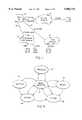
- FIG. 1diagrammatically illustrates a video teleconferencing system having multiple audiovisual terminals connected to an MCU through a variety of networks.
- FIG. 2is a block diagram of an MCU configuration.
- FIG. 3is a block diagram of a Bridge Processing Unit of the MCU configuration of FIG. 2.
- FIG. 4illustrates a conference operator queue screen in accordance with the present invention.
- FIG. 5is a state diagram illustrating the conference site states in accordance with the present invention.
- FIGS. 6A-6Billustrate attended conference scenarios in accordance with the present invention.
- FIG. 7shows an H.261 BCH block for use in the present invention.
- FIG. 8illustrates a timeline of events associated with image playback in accordance with the present invention.
- FIG. 9is a block diagram illustrating the flow of audio and video streams in an MCU according to the present invention.
- FIG. 10shows an H.221 frame used in the conferencing system of the present invention.
- FIGS. 11A-11Billustrate a flow diagram for a still image generator function in accordance with the present invention.
- FIGS. 12A-12Billustrate a flow diagram for a video bits retrieval function of the still image generator in accordance with the present invention.
- a video teleconferencing systemis shown in which audiovisual terminals A, B, C, and D are connected in a conference to an MCU 10 through a variety of communication networks 12, each network having a particular type of access interface 14 to the MCU 10, e.g., V.35/RS-449 for high-speed data networks, PRI for ISDN networks, and T1 access for private networks.
- V.35/RS-449for high-speed data networks
- PRIfor ISDN networks
- T1 access for private networkse.g., T1 access for private networks.
- incoming calls from conference participantsare automatically answered and placed in a single operator hold queue.
- an audio greeting or welcome message specific to the phone number dialed or the physical port reached at the MCUis played to the conference participant.
- a stored video clip or still image welcome messageis also transmitted to the participant. While in the queue, both types of conference participants receive music-on-hold after the initial audio greeting.
- the ability to assign audio and video clips/still images to phone numbers or MCU portsallows a conference service provider to support multiple, private-labeled conferencing services or to support customers that want their own company-specific information displayed to participants who are holding for their conferences.
- FIG. 2illustrates MCU 10 installed in a host 80386 or 80486-based PC, further disclosed in U.S. patent application Ser. No. 08/379,274, which is incorporated herein in its entirety by reference.
- the hostcan also be a Pentium®-based PC.
- MCU 10includes at least one Network Interface Unit (NIU) 20, at least one Bridge Processing Unit (BPU) 22, an optional Data Processing Unit (DPU) 23, an optional Video Processing Unit (VPU) 28 and a Host Processing Unit (HPU) 24.
- NNUNetwork Interface Unit
- BPUBridge Processing Unit
- DPUData Processing Unit
- VPUVideo Processing Unit
- HPUHost Processing Unit
- the MCU 10includes a Network Bus 34 and a BPU Bus 36.
- the Network Bus 34complies with the Multi-Vendor Integration Protocol (MVIP) while the BPU Bus 36 is a derivative of the MVIP specification.
- MVIPMulti-Vendor Integration Protocol
- External audiovisual terminals, or codecs 38connect to the MCU 10 to form conferences.
- the MCU 10also includes an Audio Interface Unit (AIU) 26 which is coupled to an external audio source 30.
- AIUAudio Interface Unit
- An operator site 25provides a workstation 27 for conference management and control through the HPU 24 and a codec 29 for use by an operator to support operator attended conferencing. While the codec 29 is shown connected to a particular NIU 20 that provides a V.35/RS-449 access interface, the codec can also be connected through other access interfaces, e.g., T1 or ISDN.
- Each codec 38typically an H.320 audiovisual terminal, connects to the MCU 10 through a communication network.
- Unsynchronized digital data frames from each codec 38are made available on the Network bus 34 through NIUs 20.
- the BPUs 22process the unsynchronized data frames from the Network Bus 34 to produce data frames aligned on an octet boundary which are made available to other BPUs 22 on the BPU bus 36.
- the BPUs 22also extract audio information from the data frames.
- the audio informationis decoded to PCM data and made available on the BPU bus 36 for mixing with audio from other codecs 38 by respective BPUs 22 in a conference.
- the BPUs 22combine compressed video information and mixed encoded audio information into frames which are placed on the Network Bus 34 for transmission to respective codecs 38.
- the optional DPU 23performs processing functions similar to the BPUs 22 to support ITU-TSS Rec. T.120 data conferencing.
- the present inventionis thus compatible with, and transparent to, T.120 data conferencing.
- the BPUs 22perform video switching within a conference by selecting video data frames from timeslots on the BPU bus 36 and routing the frames to respective codecs 38 in the conference.
- a particular BPU 22selects the appropriate video data frames based upon an MCU conference selection process. Typically, the selection process is based upon a comparison of the voice levels of the conference locations. Initially, the loudest conference location is designated the current broadcaster to be viewed by all other conference locations while the current broadcaster typically views another location. A subsequent loudest conference location becomes the current broadcaster only after the previous broadcaster has been silent for a period of time.
- an MCU operator or a particular audiovisual terminal operating in a chair control modeselects a location as the current broadcaster.
- multiple video inputsare sent to a VPU 28 where the video inputs are decompressed, mixed and recompressed into a single video stream. This single video stream is then passed back through the BPU 22 which switches the video stream to the appropriate endpoint codecs.
- the MVIP-compliant Network Bus 34comprises eight full-duplex, serial time-division multiplexed 125 ⁇ s data streams which adhere to the Mitel ST-BUS (Serial Telecom) Generic Device Specification. Each data stream operates at 2 Mbps and is divided into 32 separate timeslots. The total capacity of the bus is therefore 256 timeslots with each timeslot having a capacity of 64 Kbps.
- the digital datais space-division multiplexed across the data streams. In this way, a frame of digital data from a communications network can be multiplexed across any of the256 timeslots for intra-MCU communications.
- the MVIP-derivative BPU bus 36also referred to as an interprocessor bus, is a TDM serial bus capable of handling sixteen streams.
- each streamoperates at 2 Mbps, and has 32 timeslots, each timeslot at 64 Kbps for a total of 32 Mbps transfer rate.
- the HPU 24provides a management interface to a workstation 27 for MCU operations. Through the HPU 24, an operator can control and manage the operation of the other components.
- the HPU 24controls the setup and establishment of conferences, and performs monitoring and maintenance functions.
- Each NIU 20connects the MCU 10 with a particular communications network to a particular codec 38 through an appropriate interface port.
- the NIU 20formats the digital data frames that pass between the MCU 10 and codecs 38 for transmission within the MCU 10 and across the various communications networks.
- the most common type of NIU 20supports a single T1 or ISDN primary rate interface over which the network service (e.g., a communications carrier) has time-division-multiplexed a number of individual codec connections.
- the MCU 10can also include NIUs having interface ports that support only single codec connections.
- the frame structure for the data exchanged between the MCU 10 and the codecs 38is defined in ITU-TSS Rec. H.221.
- Each NIU 20reformats the digital data frames from the incoming line to an internal MCU format that is independent of the individual codec interfaces to the communications network. The reformatted data is then multiplexed onto the Network Bus channels for transmission to the BPUs 22.
- the BPUs 22handle video switching within conferences by selecting and routing time and space-division multiplexed digital data.
- Each BPU 22can support four codecs (audiovisual terminals) and multiple BPUs may be connected through the BPU bus 36.
- the BPU 22demultiplexes the digital data frames from the Network Bus 34, mixes the digital audio data, and multiplexes new digital data frames onto the Network Bus 34 from the mixed digital audio and the appropriate digital video and conferencing data.
- FIG. 3A detailed block diagram of BPU 22 is illustrated in FIG. 3.
- the BPU 22is segmented into four partitions (A, B,C,D), each partition having a pair of Digital Signal Processors (DSP) 40, 42 assignable to a particular codec.
- Each BPU partition (A,B,C,D)contains a first DSP (DSP1) 40 and a second DSP (DSP2) 42.
- DSP1 40transfers and analyzes data to and from the Network Bus 34 and manages a buffer for this data in SRAM memory 46 shared between DSP1 40 and DSP2 42.
- DSP2 42processes data that has been pre-processed by DSP1 40 and maintains inter-BPU communications over the BPU Bus 36.
- the DSP1 40 and DSP2 42perform their processing functions synchronously with respect to the timing on the BPU bus 36 and the Network bus 34. The processing of audio and video streams in accordance with the present invention is described further below.
- Each BPU 22also has a DSP that functions as a Control Processor (CP) 44 which maintains a list of partition associations. Because the data streams on the Network Bus 34 and BPU Bus 36 are time and space division multiplexed, the CP 44 operates a Time Division Multiplexer (TDM) having a network switch 48 and a BPU switch 50 to direct selected digital data frames from the data channels to the correct BPU partition.
- TDMTime Division Multiplexer
- the TDMmay be implemented by a Mitel MT8980D Digital Switch.
- the CP 44supports a 32 bit CP bus 47 to the DSPs 40, 42 in the four partitions (A,B,C,D). In addition, the CP 44 supports an 8 bit bus 49 to the network switch 48 and the BPU switch 50.
- the CP 44interfaces to TDM data streams through serial multiplexer 51.
- BPU configuration informationmay be stored in EEROM 53.
- the BPU 22has an HPU interface 41 which allows the HPU 24 (FIG. 2) to perform memory access of a CP SRAM memory 43 and I/O access to control the CP 44.
- Address decode block 45supports HPU I/O access to the BPU 22 using programmable switches selected by system configuration.
- the DPU 23performs two functions: 1) protocol handling of T.120 stacks for multilayer protocol (MLP) conferencing applications and 2) protocol handling, video bridging and audio processing for PCS (Intel) codec applications.
- MLPis defined in the H-series Recommendations H.200/AV.270 and will not be discussed further.
- a screen 100which illustrates conference operator queue information presented to an operator on workstation 27 (FIG. 2).
- the screen 100includes a conference site information window 102, a site action area 104, and a conference mode area 106.
- the conference site information window 102includes a list of conference sites. Each entry 102a includes fields labeled site name, site number, conference site state, and received signal state. The entries are listed chronologically with the most recently connected sites at the bottom. The operator site is not included in the list.
- pre-test timeis provided such that a conference participant experiences a transition from a preparation period to a formalized or active conference.
- An activate button 108allows the operator the choice of shortening the pre-test time and making the conference active. Once activated, or when the pre-test time expires, the conference cannot be made inactive again.
- the conference operatorselects a conference site listed in the queue of the conference site information window 102 and selects one of the actions available in the site action area 104 depending on the current state of the conference site and on the current conference mode.
- the conference site statesare shown in the state diagram of FIG. 5 and are described as follows.
- a conference site entering the operator queue of an Attended/Operator Assisted conferenceinitially is placed in a Waiting state 110. While in the Waiting state 110, the site receives music-on-hold and the audio/video greeting and waits to be assisted by an operator.
- a conference site in the Waiting state 110can move to either a Being Assisted state 112 or a Bypass state 116, depending on specific actions by the operator.
- a conference site in the Waiting state 110transitions to the Being Assisted state 112 when an operator selects the site from the operator queue and begins a subconference to check the audio and video signal quality for that site.
- a transition from the Waiting state 110 to the Bypass state 116occurs when the operator selects the site from the operator queue and sends the site into the conference without any assistance.
- a conference site in the Being Assisted state 112can move to either a Problem state 113, a Ready state 114, a Bypass state 116, or an Active state 118, depending on specific actions by the operator and on the conference state itself.
- a transition to the Problem state 113occurs when an operator determines that a problem exists with the audio and/or video signals being received from that particular site. Accordingly, the audio and video signals from a site in the Problem state 113 are not passed into an active conference until the problem is resolved. However, the site continues to receive music-on-hold and the video greeting.
- a conference sitetransitions to the Ready state 114 from the Being Assisted state 112 when the operator determines that the audio and video signal quality from the site is acceptable.
- the conferenceIn the Ready state 114, the conference is still in the pre-test period and therefore not yet active.
- the conference site in this statecontinues to receive music-on-hold and video greeting.
- the conference sitetransitions automatically from the Ready state 114 to the Active state 118 without any operator action.
- an operatorcan move a site to the Active state 118 directly from the Being Assisted state 112 if the conference has already been activated at the time the operator concludes offering assistance to the site. In either case, once a site reaches the Active state 118, the music-on-hold and video greeting are terminated and the site receives the normal conference audio and video signals instead.
- a conference site in this statecontinues to receive the music-on-hold and video greeting.
- the sitetransitions from this state to the Active state 118 automatically without operator action once the associated conference is activated.
- a site in the Ready state 114, the Bypass state 116, or the Active state 118may develop technical problems requiring assistance from the operator. Therefore, an operator can move a site from any of these states back into the Being Assisted state 112 for troubleshooting as needed.
- the transitions out of the Being Assisted state 112 to the Ready, Bypass, or Active statesis then the same as described above.
- buttonsare labeled Attach 104a, Detach/No Problem 104b, Detach/Problem 104c and Bypass 104d.
- Attach 104aDetach/No Problem 104b
- Detach/Problem 104cDetach/Problem 104c
- Bypass 104dOne of the sites must be selected in the site information window 102 in order to make the site action buttons functional.
- the Attach button 104aallows the operator to have a one-on-one conference with the selected site. This site action can be used at any time for the entire duration of the conference so long as the operator site is not busy helping another site. This is the subconferencing feature of the conference. Note that the site itself cannot initiate or signal for assistance within the confines of the conference. The site can only request assistance using a separate telephone connection to the operator. Both the Detach/No Problem button 104b and the Detach/Problem button 104c allow the operator to terminate the subconference. Upon selection of the Detach/No Problem button 104b, the site state will then be shown in the site information window 102 as the Ready state 114 if the conference is still pending or the Active state 118 if the conference is active.
- the Detach/Problem button 104callows the operator to suspend the site in the conference operator queue and mark the site as having a problem. This site will now be in the Problem state 113 and will not be an active participant in the conference. This can be helpful for troubleshooting a conference that is having difficulties.
- the operatorcan systematically place sites in the queue temporarily to diagnose technical problems.
- the Bypass button 104dallows the operator to send the site into the conference without having a one-on-one conference. This button is available only when the conference site has not been helped by the operator yet, i.e., the site is currently in the Waiting state 110.
- the MCU of the present inventionprovides for transition or conversion between conferencing modes.
- An unattended conferencecan be converted to an attended conference via a conference control function that results in an operator site being added.
- the conferenceis automatically converted to an unattended conference.
- the process of adding and deleting an operator siteis performed via the conference hold queue screen 100.
- FIG. 6Aan operator attended conference timeline is shown in which site A enters the conference hold queue at point A' followed by site B at point B'. Sites A and B remain in the conference queue for a period 300 and 302, respectively.
- each siteinitially receives music on hold. Once each site's video is ready, the first audio "welcome" message is received along with the video greeting. This is then followed by the second "operator-assisting" message. While conference participants at both sites are hearing music-on-hold and seeing the video greeting, the operator receives an indication in the conference hold queue screen 100 (FIG. 4) that both sites are currently in the Waiting state.
- the operatorconducts a subconference with Site A.
- the operatordetaches site A from the subconference at point A" and the site enters the Ready state for the pre-test period of the conference.
- Site Acontinues to receive music-on-hold and the video greeting while waiting for the conference to start.
- the operatorrepeats the same actions with respect to Site B during period 302.
- site Bdetaches from the subconference with the operator and enters the Ready state for the remainder of the pre-test conference period.
- Sites A and Bbecome active in the conference.
- Site Cattempts to join the conference after the pre-test period at point C'.
- Site Cis placed in the conference hold queue at point C' for a period 304, during which it receives assistance from the operator in a subconference. However, when the operator detaches site C from the subconference at point C", site C is cut directly into the active conference. Thereafter, sites A, B, and C are in the active conference.
- a timelineis shown in which conference sites A and B directly join an unattended conference at points A' and B', respectively, without having spent time in a conference hold queue.
- Each sitemay receive music on hold, the first audio message and video greeting for a period of time as specified by the conference definition.
- sites A and Bthen enter immediately into active conferencing.
- the operatordecides to change the scheduled unattended conference mode to an attend/operator assisted conference while the conference is underway.
- site Cattempts to join the conference and is placed in the queue for a period 308, during which it receives assistance from the operator in a subconference.
- site Cis cut directly into the active conference.
- site Bhas been in the active conference for a period 306
- the operatordecides to have a subconference with site B because trouble is indicated for site B's audio in the site window 102.
- the operatorreattaches site B from the conference queue at point B" to start a subconference and begins an investigation.
- the operatordetaches site B from the subconference and site B rejoins the active conference at point B".
- pre-recorded audio and video messagesart stored in system storage such as a hard disk, of the MCU 10.
- the BPU 22includes a DSP pair (DSP1, DSP2 labeled 40, 42 in FIG. 3) for each conference participant/codec.
- each participantis assigned to a DSP1, DSP2 pair.
- the audio and video messagesare retrieved from the system storage and are downloaded to the DSP1 private SRAM 46 through the HPU Interface 41 (FIG. 3).
- two audio messagesare downloaded, the first a "welcome” message and the second an "operator will assist you" message.
- the audio messagesare stored in the DSP1 private RAM 46 as G.711 PCM data in 32 bit words.
- G.711 PCMpulse code modulation
- the datais extracted from the buffer and G.711 expanded by the DSP1.
- the expanded audiois then passed to the DSP2 where it replaces the audio sample normally present on the BPU bus 36.
- the video imageis also stored in the DSP1 private RAM 46, encoded as a single H.261 QCIF intra mode frame.
- QCIFquarter-common intermediate format
- the imageis stored in an integer number of H.261 BCH blocks (512 bits or 16 words each).
- a single H.261 BCH frameis shown in FIG. 7.
- the 512 bit frameincludes a synch bit S and a fill flag bit F, followed by video bits.
- a BCH error checking codecompletes the frame.
- a timelineshows events associated with playback of the video image from the DSP1 private RAM to the associated codec 38.
- a freeze picture commandis sent to the associated conference participant's codec, shown as "START" in FIG. 8.
- the normal output video stream to that codecis then replaced with H.261 fill frames for a sufficient period to ensure codec synchronization.
- the image blocksare then read out f memory and placed into the H.221 framing. After all the image blocks have been sent, fill frames are sent to adjust the picture rate. The amount of fill frames required depends upon the frame rate negotiated with the endpoint codec 38.
- the image blocks followed by the fill framesare continuously sent until the video image is stopped by another command from the DSP CP 44.
- the codecdisplays the video image after some number of repetitions of the image blocks.
- the first audio messageis synchronized to be sent when the codec displays the received video image.
- the video image maximum sizeis about 8K bytes, but the size can vary depending on the picture content.
- the first audio message, the "welcome” message, and the second audio message, the "operator will assist you” message,can last up to 9 seconds. It should be noted that these message lengths are based on the storage constraints of a particular embodiment of a BPU 22.
- the inventioncontemplates storage of multiple video and audio messages customized to individual conference participants or conference service providers.
- the audio and video messagescould be customized to the language spoken by the conference participant.
- a video message customized for a particular conference service providermay include a specific service logo.
- the preferred embodimentemploys a still video image, a series of images as in a video clip could be used instead.
- conference participantsreceive music-on-hold before a conference becomes active.
- the Audio Interface Unit (AIU) 26(FIG. 2) provides a music on hold signal in G.711 format to the Network bus 34 from an audio source 30.
- the music-on-hold signalis assigned a dedicated timeslot on the Network bus 34. All conference participants that are in the conference states Waiting 110, Problem 113, Bypass 116 or Ready 114 (FIG. 5) receive music-on-hold from this timeslot.
- FIG. 9the flow of audio and video streams in accordance with the present invention will be described.
- DSP1 40, DSP2 42 pairis shown representing BPU 22 (FIG. 3) to simplify the description.
- the normal flowwill first be described followed by the flow according to the present invention.
- a codec 38(shown here functionally as separate codec input 38a and codec output 38b) outputs an H.221 frame 120 which is coupled to the Network bus 34.
- the H.221 framewhich includes audio, video and control information, is routed to the particular assigned DSP1 40 where a splitting function 142 is performed to split the H.221 frame 120 into separate audio, video, and control streams 122, 124 and 126, respectively.
- the control stream 126is passed to a control function 144 for communication to the DSP CP 44 (FIG. 3).
- the video stream 124is passed to the BPU bus 36 and made available for switching to other codecs 38.
- the audio stream 122is passed to an audio decoder 148 in DSP2.
- the audio decoder 148decodes the compressed audio stream 122 according to the coding algorithm for the assigned codec 38 (e.g., G.711, G.728, G.722, PT724).
- the decoder 148passes the expanded audio 123 to the BPU bus 36 where it is made available for switching to other codecs 38.
- audio and video streams 125, 126are selected from-the BPU bus 36 and passed to DSP2 42.
- the selected video stream 126is passed through DSP2 42 to DSP1 40.
- the expanded audio stream 125is passed to an audio encoder 146 which encodes the expanded audio stream-according to the coding algorithm for the assigned codec 38.
- the encoded audio stream 127 and the selected video stream 126are combined in combiner 136 with control information from control 134 to form a complete H.221 frame 128 that is placed on the Network bus 34 and transmitted to the assigned codec input portion 38a.
- DSP1 40processes these messages, shown separately as still image data block 130 and G.711 message data block 138, as follows.
- a G.711 encoded audio message data stream 150is passed to a G.711 decoder 140 in the DSP1 40.
- the decoder 140provides an expanded audio stream 156 to the audio encoder 146 in DSP2 42.
- the audio encoder 146switches from encoding the expanded audio stream 125 to encoding the audio message stream 156 instead.
- the audio message stream 156is similarly encoded according to the algorithm of the assigned codec 38 and passed to the combiner 136. If the conference state instead requires music on hold, the G.711 decoder 140 switches to decode a music on hold stream 152 received over Network bus 34 from the AIU 26.
- DSP1 40retrieves the still image data from memory block 130 as a video data stream 158 that is passed to a still image generator 132.
- the still image data stream 158 taken from 512 bit blocks of an H.261 intramode framelacks H.221 framing.
- the still image generator 132described further below, formats the video image data into the correct video block locations of H.221 frames.
- the DSP1 40selects this H.221 framed video stream 160 instead of the normal selected video stream 126 from the BPU bus 36 and combines it with the audio message or music on hold stream 127 to complete the H.221 frame 128 for transmission to the codec 38a.
- the image generator 132performs a formatting function to map 512 bit blocks of image data into appropriate video bit locations of an H.221 frame. Essentially, the image generator 132 performs a portion of the H.221 framing that is normally performed by an endpoint codec. The combiner 136 completes the H.221 framing by combining audio, video and control streams into the complete H.221 frame.
- FIG. 10illustrates a typical bandwidth allocation for an H.221 frame in a two channel, 128kbps ISDN connection.
- the H.221 frameis two columns or channels by 80 rows. Each channel is 8 bits wide.
- the first channel, labeled the I-channelincludes bandwidth allocated for audio according to one of the several audio standards G.711, G.722, G.728 or PT724.
- the remaining bandwidth in the I-channel and in the second channelis allocated to video and control information.
- the control informationis allocated one bit at the end position of each channel for each of the first 16 rows of the H.221 frame.
- the video bitstake up the remaining bit positions as shown in FIG. 10.
- the mapping function of the image generator 132is illustrated in FIGS. 11A-11B.
- a video bit pattern appropriate for the rateis selected from memory.
- the video bit patternindicates the locations or positions for allocating the image data to the H.221 frame.
- the patternis stored in a table which comprises one or more entries having the following fields:
- the tablemight have the following entries:
- the mapping processbegins at step 200 for each row of the H.221 frame.
- N video bitsare retrieved from the still image data store 130 (FIG. 9), or from a fill frame, where N equals the value stored in the I Num 1 field of the current pattern table entry.
- the bit pattern for the current rowis then set according to the retrieved video bits shifted by the value of the I Shift 1 field in the current pattern table entry to properly place the video bits in the first video block of the I-channel.
- the value of the I Num 2 field in the current pattern table entryis greater than zero, indicating that there are video bits in a second video block of the I-channel, then the next N video bits are retrieved from memory (FIG.
- Nthe value of the I Num 2 field of the current pattern table entry at step 214.
- These video bits for the second video block of the I-channelare added to the bit pattern shifted by the value of the I Shift 2 field. Processing continues at step 216.
- processingcontinues at step 216.
- the remainder of the processingrelates to handling the other (non-I) channels of the H.221 frame.
- a time slot counteris set to zero and a shift value counter is set to 24 plus the value of the O Shift field at step 216.
- the time slotrepresents one 8 bit column in the H.221 frame.
- step 218processing continues at step 218 wherein the time slot counter is incremented.
- step 220if all the time slots have been processed, then the bit pattern is saved in an output buffer at step 222 and the processing of the next H.221 row begins at step 200. If all the time slots have not been processed at step 220, then the shift value counter is set to the previous value minus 8 at step 224.
- step 226a check is made to see if the word is completed by determining if the shift value has become negative. If the shift value is positive, processing then continues at step 230. If the shift value is negative, indicating that the word is completed, then the bit pattern is saved in the output buffer at step 228. The shift value is also reset to the value set in step 216 and the bit pattern is cleared.
- a checkis made to see if the time slot counter is greater than a start time slot parameter to make sure the current time slot is in a range for replacement. If the current time slot count is in the range, then at step 232, the next N video bits are retrieved from storage (FIG. 9) or from the fill frame, where N equals the value of the O Num field of the current pattern table entry. The bits are placed into the correct location specified by the current shift value. Processing continues in a loop at step 218.
- Each of steps 210, 214 and 232includes retrieving N video bits from the still image buffer or from the fill frame.
- a process for retrieving the N bitsis shown in FIGS. 12A-12B.
- a Remain counterinitially set to a value of -32, is incremented by the value of N.
- a bit maskis constructed with all 1's, except that the lower N bits are set to 0's.
- a data pointeris initially set to point to the start of the fill block.
- the outputis initially set to the value stored at the data pointer value shifted by the value of the Remain counter.
- a checkis made to see if there are enough bits in the current word by determining whether the Remain counter has become non-negative. If the Remain counter is still negative, then at step 246, the output is masked to N bits and the processing ends.
- step 248the data pointer is moved to the next word.
- a check for the BCH frame boundaryis made at step 250, wherein a BCH frame comprises 16 words. If the BCH frame boundary is not detected, then at step 252 additional bits are retrieved.
- the Remain counteris adjusted by 32 and the Output is set to the previous value of the Output combined with the value stored at the data pointer value shifted by the value of the Remain counter. The Output is then masked to N bits at step 246 and processing ends.
- a frame counter that indicates the number of fill frames that need to be sent to synchronize the endpoint codechas an initial value typically equal to 70 and is stored as a negative counter.
- the frame counteris incremented.
- a checkis made at step256 to determine whether the frame counter is still negative, indicating that fill frames are being sent. If the frame counter is negative, then at step 258, the data pointer is set to the start of the fill block in memory. Processing continues at step 274.
- the DSP CP 44(FIG. 3) is sent a sync message by DSP1 to allow the CP to synchronize the still image and the audio messages. This message is sent at step 272. To reach that step, a check is made at step 268 to see if the synchronization message has not been sent and whether the image data has been sent M times, where M equals the number of times to send the image before codec synchronization is achieved. M is typically set to 3. If the sync message has been sent at step 268 or if the picture has not been sent M times at step 270, then processing continues at step 274. A sync bit from the BCH frame sync pattern is added to the most significant bit of the current word at step 274. If the last bit of the sync pattern has been reached at step 276, then the sync pattern is reset at step 278. Processing continues following connector C back to step 252 (FIG. 12A).
Landscapes
- Engineering & Computer Science (AREA)
- Multimedia (AREA)
- Signal Processing (AREA)
- General Engineering & Computer Science (AREA)
- Computer Networks & Wireless Communication (AREA)
- Two-Way Televisions, Distribution Of Moving Picture Or The Like (AREA)
- Telephonic Communication Services (AREA)
- Data Exchanges In Wide-Area Networks (AREA)
Abstract
Description
TABLE 1______________________________________ Attended/Operator Attended/From/To Assisted Bypass Unattended______________________________________Attended/ NA Any sites in Operator site isOperator the Waiting deleted. AllAssisted state will sites, except be auto- inactive sites, maticaily regardless of state sent into are sent into the the conference after conference operator via bypass. acknowledgment through a confirmation dialog box.Attended/ Any newly arrived NA Operator site isBypass sites become deleted. All Waiting sites. sites, except The operator can inactive sites, now help these regardless of state sites into the are sent into the conference. conference after an operator acknowledgment through a confirmation dialog box.Unattended The operator is The operator NA prompted to add is prompted an operator site. to add an Once the operator operator site is correctly site. Once added, attended/ the operator operator assisted site is mode is entered. correctly added, attended/ bypass mode is entered.______________________________________
______________________________________Row The ending row number for this pattern.I Num 1 Number of bits in first vieeo block for I channel.I Shift 1 Locations for first video block.I Num 2 Number of bits in second video block for I channel (Optional).I Shift 2 Location of second video block.O Num Number of video bits in each timeslot for other channels (Non-I channel).O Shift Location of video block in other channels.______________________________________
______________________________________Row I Num 1 I Shift 1 I Num 2 I Shift 2 0Num 0 Shift______________________________________16 1 1 0 0 7 080 2 0 0 0 8 0______________________________________
Claims (32)
Priority Applications (2)
| Application Number | Priority Date | Filing Date | Title |
|---|---|---|---|
| US08/790,289US5886734A (en) | 1997-01-28 | 1997-01-28 | Apparatus and method for storage and playback of video images and audio messages in multipoint videoconferencing |
| US09/273,966US5990933A (en) | 1997-01-28 | 1999-03-22 | Apparatus and method for storage and playback of video images and audio messages in multipoint videoconferencing |
Applications Claiming Priority (1)
| Application Number | Priority Date | Filing Date | Title |
|---|---|---|---|
| US08/790,289US5886734A (en) | 1997-01-28 | 1997-01-28 | Apparatus and method for storage and playback of video images and audio messages in multipoint videoconferencing |
Related Child Applications (1)
| Application Number | Title | Priority Date | Filing Date |
|---|---|---|---|
| US09/273,966ContinuationUS5990933A (en) | 1997-01-28 | 1999-03-22 | Apparatus and method for storage and playback of video images and audio messages in multipoint videoconferencing |
Publications (1)
| Publication Number | Publication Date |
|---|---|
| US5886734Atrue US5886734A (en) | 1999-03-23 |
Family
ID=25150237
Family Applications (2)
| Application Number | Title | Priority Date | Filing Date |
|---|---|---|---|
| US08/790,289Expired - LifetimeUS5886734A (en) | 1997-01-28 | 1997-01-28 | Apparatus and method for storage and playback of video images and audio messages in multipoint videoconferencing |
| US09/273,966Expired - LifetimeUS5990933A (en) | 1997-01-28 | 1999-03-22 | Apparatus and method for storage and playback of video images and audio messages in multipoint videoconferencing |
Family Applications After (1)
| Application Number | Title | Priority Date | Filing Date |
|---|---|---|---|
| US09/273,966Expired - LifetimeUS5990933A (en) | 1997-01-28 | 1999-03-22 | Apparatus and method for storage and playback of video images and audio messages in multipoint videoconferencing |
Country Status (1)
| Country | Link |
|---|---|
| US (2) | US5886734A (en) |
Cited By (42)
| Publication number | Priority date | Publication date | Assignee | Title |
|---|---|---|---|---|
| US5990933A (en)* | 1997-01-28 | 1999-11-23 | Videoserver, Inc. | Apparatus and method for storage and playback of video images and audio messages in multipoint videoconferencing |
| US6163798A (en)* | 1996-09-10 | 2000-12-19 | Fuzion Technologies, Inc. | Multi-head video teleconferencing station |
| US6401122B1 (en)* | 1996-07-19 | 2002-06-04 | Fujitsu Limited | Communication management apparatus |
| US20020188731A1 (en)* | 2001-05-10 | 2002-12-12 | Sergey Potekhin | Control unit for multipoint multimedia/audio system |
| US20030174202A1 (en)* | 2000-01-13 | 2003-09-18 | Noam Eshkoli | Method and system for controlling multimedia video communication |
| US6631410B1 (en) | 2000-03-16 | 2003-10-07 | Sharp Laboratories Of America, Inc. | Multimedia wired/wireless content synchronization system and method |
| US6757005B1 (en)* | 2000-01-13 | 2004-06-29 | Polycom Israel, Ltd. | Method and system for multimedia video processing |
| US20050058287A1 (en)* | 2003-09-12 | 2005-03-17 | Bran Ferren | Method and apparatus for synchronizing audio and video in encrypted videoconferences |
| US20050065779A1 (en)* | 2001-03-29 | 2005-03-24 | Gilad Odinak | Comprehensive multiple feature telematics system |
| WO2005074280A1 (en) | 2004-01-16 | 2005-08-11 | Huawei Technologies Co., Ltd. | Method for displaying conference information in video conference system |
| US20050213733A1 (en)* | 2001-12-31 | 2005-09-29 | Polycom, Inc. | Speakerphone and conference bridge which receive and provide participant monitoring information |
| US20050213517A1 (en)* | 2000-12-26 | 2005-09-29 | Polycom, Inc. | Conference endpoint controlling audio volume of a remote device |
| US20050213736A1 (en)* | 2001-12-31 | 2005-09-29 | Polycom, Inc. | Speakerphone establishing and using a second connection of graphics information |
| US20050213732A1 (en)* | 2001-12-31 | 2005-09-29 | Polycom, Inc. | Conference bridge which decodes and responds to control information embedded in audio information |
| US20050213734A1 (en)* | 2001-12-31 | 2005-09-29 | Polycom, Inc. | Conference bridge which detects control information embedded in audio information to prioritize operations |
| US20050213730A1 (en)* | 2000-12-26 | 2005-09-29 | Polycom, Inc. | Conference endpoint instructing conference bridge to dial phone number |
| US20050213726A1 (en)* | 2001-12-31 | 2005-09-29 | Polycom, Inc. | Conference bridge which transfers control information embedded in audio information between endpoints |
| US20050213739A1 (en)* | 2001-05-10 | 2005-09-29 | Polycom, Inc. | Conference endpoint controlling functions of a remote device |
| US20050213729A1 (en)* | 2000-12-26 | 2005-09-29 | Polycom,Inc. | Speakerphone using a secure audio connection to initiate a second secure connection |
| US20050213727A1 (en)* | 2001-05-10 | 2005-09-29 | Polycom, Inc. | Speakerphone and conference bridge which request and perform polling operations |
| US20050213735A1 (en)* | 2000-12-26 | 2005-09-29 | Polycom, Inc. | Speakerphone transmitting URL information to a remote device |
| US20050262256A1 (en)* | 2004-04-22 | 2005-11-24 | Benq Corporation | Method and device for multimedia processing |
| US20060149815A1 (en)* | 2004-12-30 | 2006-07-06 | Sean Spradling | Managing participants in an integrated web/audio conference |
| US20060282184A1 (en)* | 2005-06-08 | 2006-12-14 | Polycom, Inc. | Voice interference correction for mixed voice and spread spectrum data signaling |
| US20070047624A1 (en)* | 2005-06-08 | 2007-03-01 | Polycom, Inc | Mixed voice and spread spectrum data signaling with enhanced concealment of data |
| US20070140456A1 (en)* | 2001-12-31 | 2007-06-21 | Polycom, Inc. | Method and apparatus for wideband conferencing |
| EP1601160A3 (en)* | 2004-05-27 | 2007-10-10 | Microsoft Corporation | Efficient routing of real-time multimedia information |
| US20080002022A1 (en)* | 2006-06-30 | 2008-01-03 | Sony Ericsson Mobile Communications Ab | Call holding for a video call in a mobile communication device |
| US20080143819A1 (en)* | 2004-04-16 | 2008-06-19 | Polycom, Inc. | Conference link between a speakerphone and a video conference unit |
| US7653013B1 (en)* | 2000-06-01 | 2010-01-26 | Nortel Networks Limited | Conferencing systems with enhanced capabilities |
| US7796565B2 (en) | 2005-06-08 | 2010-09-14 | Polycom, Inc. | Mixed voice and spread spectrum data signaling with multiplexing multiple users with CDMA |
| US7821918B2 (en) | 2002-03-01 | 2010-10-26 | Polycom, Inc. | System and method for communication channel and device control via an existing audio channel |
| US7978838B2 (en) | 2001-12-31 | 2011-07-12 | Polycom, Inc. | Conference endpoint instructing conference bridge to mute participants |
| EP2381683A1 (en)* | 2010-04-23 | 2011-10-26 | Orange Vallee | Method and system for managing a live video broadcast streaming session |
| US8223942B2 (en) | 2001-12-31 | 2012-07-17 | Polycom, Inc. | Conference endpoint requesting and receiving billing information from a conference bridge |
| US8705719B2 (en) | 2001-12-31 | 2014-04-22 | Polycom, Inc. | Speakerphone and conference bridge which receive and provide participant monitoring information |
| US8885523B2 (en) | 2001-12-31 | 2014-11-11 | Polycom, Inc. | Speakerphone transmitting control information embedded in audio information through a conference bridge |
| US8934381B2 (en) | 2001-12-31 | 2015-01-13 | Polycom, Inc. | Conference endpoint instructing a remote device to establish a new connection |
| US8947487B2 (en) | 2001-12-31 | 2015-02-03 | Polycom, Inc. | Method and apparatus for combining speakerphone and video conference unit operations |
| US8977683B2 (en) | 2000-12-26 | 2015-03-10 | Polycom, Inc. | Speakerphone transmitting password information to a remote device |
| US20190132367A1 (en)* | 2015-09-11 | 2019-05-02 | Barco N.V. | Method and system for connecting electronic devices |
| US12425545B1 (en)* | 2023-07-10 | 2025-09-23 | Zoom Communications, Inc. | Multi-step enablement of media input devices during virtual conferences |
Families Citing this family (42)
| Publication number | Priority date | Publication date | Assignee | Title |
|---|---|---|---|---|
| US6839734B1 (en)* | 1998-09-21 | 2005-01-04 | Microsoft Corporation | Multimedia communications software with network streaming and multi-format conferencing |
| US6438136B1 (en)* | 1998-10-09 | 2002-08-20 | Microsoft Corporation | Method for scheduling time slots in a communications network channel to support on-going video transmissions |
| US6519004B1 (en) | 1998-10-09 | 2003-02-11 | Microsoft Corporation | Method for transmitting video information over a communication channel |
| US6445701B1 (en)* | 1998-10-09 | 2002-09-03 | Microsoft Corporation | Channel access scheme for use in network communications |
| US6507587B1 (en) | 1998-10-09 | 2003-01-14 | Microsoft Corporation | Method of specifying the amount of bandwidth to reserve for use in network communications |
| US6621834B1 (en)* | 1999-11-05 | 2003-09-16 | Raindance Communications, Inc. | System and method for voice transmission over network protocols |
| US6535909B1 (en)* | 1999-11-18 | 2003-03-18 | Contigo Software, Inc. | System and method for record and playback of collaborative Web browsing session |
| US7349944B2 (en)* | 1999-11-18 | 2008-03-25 | Intercall, Inc. | System and method for record and playback of collaborative communications session |
| US20020138842A1 (en)* | 1999-12-17 | 2002-09-26 | Chong James I. | Interactive multimedia video distribution system |
| US7328239B1 (en)* | 2000-03-01 | 2008-02-05 | Intercall, Inc. | Method and apparatus for automatically data streaming a multiparty conference session |
| US6606112B1 (en)* | 2000-03-16 | 2003-08-12 | Tandberg Telecom As | Composite-video generation from different-rate constituents |
| US20020077117A1 (en)* | 2000-12-15 | 2002-06-20 | Jocelyn Cloutier | Synchronous transmission of data with network remote control |
| US6853719B2 (en)* | 2001-03-22 | 2005-02-08 | Nortel Networks Limited | Provision of media content to telephony callers on-hold |
| EP1454492A4 (en)* | 2001-07-18 | 2005-01-05 | Polycom Inc | SYSTEM AND METHOD FOR IMPROVING THE QUALITY OF VIDEO COMMUNICATION OVER A PACKET NETWORK |
| US20080158337A1 (en)* | 2001-12-15 | 2008-07-03 | John William Richardson | Videoconference Bandwidth Selection Mechanism |
| US6757260B2 (en) | 2002-06-20 | 2004-06-29 | Thomson Licensing S.A. | Ancillary information transmission while user is on hold during a telecommunications device teleconference |
| AU2004211236B2 (en) | 2003-02-10 | 2009-04-02 | Open Invention Network, Llc | Methods and apparatus for automatically adding a media component to an established multimedia collaboration session |
| US7529798B2 (en) | 2003-03-18 | 2009-05-05 | Intercall, Inc. | System and method for record and playback of collaborative web browsing session |
| US6970547B2 (en) | 2003-05-12 | 2005-11-29 | Onstate Communications Corporation | Universal state-aware communications |
| US6963353B1 (en)* | 2003-05-14 | 2005-11-08 | Cisco Technology, Inc. | Non-causal speaker selection for conference multicast |
| US7814150B1 (en)* | 2003-06-03 | 2010-10-12 | Cisco Technology, Inc. | Apparatus and method to bridge telephone and data networks |
| US7064511B2 (en)* | 2004-01-16 | 2006-06-20 | Standard Microsystems Corporation | Autofan combination of zones |
| US20060168637A1 (en)* | 2005-01-25 | 2006-07-27 | Collaboration Properties, Inc. | Multiple-channel codec and transcoder environment for gateway, MCU, broadcast and video storage applications |
| US20070192427A1 (en)* | 2006-02-16 | 2007-08-16 | Viktors Berstis | Ease of use feature for audio communications within chat conferences |
| FR2897997A1 (en)* | 2006-02-27 | 2007-08-31 | France Telecom | Interactive television service direct broadcast system for telecasting video images, has terminals connected with reception server connected with conference and computing servers, where each server connects terminals connected to server |
| US8953756B2 (en) | 2006-07-10 | 2015-02-10 | International Business Machines Corporation | Checking for permission to record VoIP messages |
| DE102006032088A1 (en)* | 2006-07-11 | 2008-01-17 | Infineon Technologies Ag | Communication terminal, method for sending communication data, conference server equipment and method for forwarding communication data |
| US8266535B2 (en) | 2006-09-11 | 2012-09-11 | Broadnet Teleservices, Llc | Teleforum apparatus and method |
| US8503622B2 (en)* | 2006-09-15 | 2013-08-06 | International Business Machines Corporation | Selectively retrieving VoIP messages |
| US20080107045A1 (en)* | 2006-11-02 | 2008-05-08 | Viktors Berstis | Queuing voip messages |
| US8542266B2 (en)* | 2007-05-21 | 2013-09-24 | Polycom, Inc. | Method and system for adapting a CP layout according to interaction between conferees |
| KR101366330B1 (en)* | 2007-06-05 | 2014-02-20 | 엘지전자 주식회사 | Method for outputting information and Terminal using this same |
| EP2019522B1 (en)* | 2007-07-23 | 2018-08-15 | Polycom, Inc. | Apparatus and method for lost packet recovery with congestion avoidance |
| US20100309094A1 (en)* | 2009-06-08 | 2010-12-09 | Castleman Mark | Methos and apparatus for remote interaction using a partitioned display |
| US8286084B2 (en)* | 2009-06-08 | 2012-10-09 | Swakker Llc | Methods and apparatus for remote interaction using a partitioned display |
| US20100309196A1 (en)* | 2009-06-08 | 2010-12-09 | Castleman Mark | Methods and apparatus for processing related images of an object based on directives |
| US9516272B2 (en) | 2010-03-31 | 2016-12-06 | Polycom, Inc. | Adapting a continuous presence layout to a discussion situation |
| US8223189B2 (en) | 2010-07-09 | 2012-07-17 | Dialogic Corporation | Systems and methods of providing video features in a standard telephone system |
| CN101895719B (en)* | 2010-08-05 | 2012-03-14 | 杭州华三通信技术有限公司 | Method for controlling video playing by utilizing video conference terminal, system and equipment thereof |
| US20120278408A1 (en)* | 2011-04-29 | 2012-11-01 | Crestron Electronics Inc. | Meeting Management System Including Automated Equipment Setup |
| US10044871B2 (en) | 2011-04-29 | 2018-08-07 | Crestron Electronics, Inc. | Conference system including automated equipment setup |
| US9179095B2 (en)* | 2012-09-27 | 2015-11-03 | Avaya Inc. | Scalable multi-videoconferencing system |
Citations (5)
| Publication number | Priority date | Publication date | Assignee | Title |
|---|---|---|---|---|
| US4516156A (en)* | 1982-03-15 | 1985-05-07 | Satellite Business Systems | Teleconferencing method and system |
| US4691347A (en)* | 1985-02-15 | 1987-09-01 | American Telephone And Telegraph Company, At&T Bell Laboratories | Method and apparatus for controlling a conference |
| WO1996042152A1 (en)* | 1995-06-13 | 1996-12-27 | Multilink, Inc. | Audio-video conferencing system |
| US5600646A (en)* | 1995-01-27 | 1997-02-04 | Videoserver, Inc. | Video teleconferencing system with digital transcoding |
| US5710591A (en)* | 1995-06-27 | 1998-01-20 | At&T | Method and apparatus for recording and indexing an audio and multimedia conference |
Family Cites Families (1)
| Publication number | Priority date | Publication date | Assignee | Title |
|---|---|---|---|---|
| US5886734A (en)* | 1997-01-28 | 1999-03-23 | Videoserver, Inc. | Apparatus and method for storage and playback of video images and audio messages in multipoint videoconferencing |
- 1997
- 1997-01-28USUS08/790,289patent/US5886734A/ennot_activeExpired - Lifetime
- 1999
- 1999-03-22USUS09/273,966patent/US5990933A/ennot_activeExpired - Lifetime
Patent Citations (5)
| Publication number | Priority date | Publication date | Assignee | Title |
|---|---|---|---|---|
| US4516156A (en)* | 1982-03-15 | 1985-05-07 | Satellite Business Systems | Teleconferencing method and system |
| US4691347A (en)* | 1985-02-15 | 1987-09-01 | American Telephone And Telegraph Company, At&T Bell Laboratories | Method and apparatus for controlling a conference |
| US5600646A (en)* | 1995-01-27 | 1997-02-04 | Videoserver, Inc. | Video teleconferencing system with digital transcoding |
| WO1996042152A1 (en)* | 1995-06-13 | 1996-12-27 | Multilink, Inc. | Audio-video conferencing system |
| US5710591A (en)* | 1995-06-27 | 1998-01-20 | At&T | Method and apparatus for recording and indexing an audio and multimedia conference |
Non-Patent Citations (6)
| Title |
|---|
| "A Standards-Based Multimedia Conferencing Bridge," AT&T Technical Journal, pp. 41-49 (Jan.-Feb. 1993). |
| "British Telecom Chooses Video Server Multimedia Conference Servers for the Worlds's First coordinator Attended Videoconferencing Service," http;//www.videoserver.com/htm/press29.htm, pp. 1-2 (Aug. 6, 1996). |
| "Multilink Announces Availability of System 80 Videoconferencing Bridge," http://www.multilink.com/sys80.htm, pp. 1-2 (May 21, 1996). |
| A Standards Based Multimedia Conferencing Bridge, AT&T Technical Journal, pp. 41 49 (Jan. Feb. 1993).* |
| British Telecom Chooses Video Server Multimedia Conference Servers for the Worlds s First coordinator Attended Videoconferencing Service, http;//www.videoserver.com/htm/press29.htm, pp. 1 2 (Aug. 6, 1996).* |
| Multilink Announces Availability of System 80 Videoconferencing Bridge, http://www.multilink.com/sys80.htm, pp. 1 2 (May 21, 1996).* |
Cited By (71)
| Publication number | Priority date | Publication date | Assignee | Title |
|---|---|---|---|---|
| US6401122B1 (en)* | 1996-07-19 | 2002-06-04 | Fujitsu Limited | Communication management apparatus |
| US6163798A (en)* | 1996-09-10 | 2000-12-19 | Fuzion Technologies, Inc. | Multi-head video teleconferencing station |
| US5990933A (en)* | 1997-01-28 | 1999-11-23 | Videoserver, Inc. | Apparatus and method for storage and playback of video images and audio messages in multipoint videoconferencing |
| US7542068B2 (en) | 2000-01-13 | 2009-06-02 | Polycom, Inc. | Method and system for controlling multimedia video communication |
| US20030174202A1 (en)* | 2000-01-13 | 2003-09-18 | Noam Eshkoli | Method and system for controlling multimedia video communication |
| US6757005B1 (en)* | 2000-01-13 | 2004-06-29 | Polycom Israel, Ltd. | Method and system for multimedia video processing |
| US7185090B2 (en) | 2000-03-16 | 2007-02-27 | Sharp Laboratories Of America, Inc. | Multimedia wired/wireless content synchronization method |
| US6631410B1 (en) | 2000-03-16 | 2003-10-07 | Sharp Laboratories Of America, Inc. | Multimedia wired/wireless content synchronization system and method |
| US7653013B1 (en)* | 2000-06-01 | 2010-01-26 | Nortel Networks Limited | Conferencing systems with enhanced capabilities |
| US8964604B2 (en) | 2000-12-26 | 2015-02-24 | Polycom, Inc. | Conference endpoint instructing conference bridge to dial phone number |
| US7864938B2 (en) | 2000-12-26 | 2011-01-04 | Polycom, Inc. | Speakerphone transmitting URL information to a remote device |
| US20050213517A1 (en)* | 2000-12-26 | 2005-09-29 | Polycom, Inc. | Conference endpoint controlling audio volume of a remote device |
| US9001702B2 (en) | 2000-12-26 | 2015-04-07 | Polycom, Inc. | Speakerphone using a secure audio connection to initiate a second secure connection |
| US8948059B2 (en) | 2000-12-26 | 2015-02-03 | Polycom, Inc. | Conference endpoint controlling audio volume of a remote device |
| US8977683B2 (en) | 2000-12-26 | 2015-03-10 | Polycom, Inc. | Speakerphone transmitting password information to a remote device |
| US20050213730A1 (en)* | 2000-12-26 | 2005-09-29 | Polycom, Inc. | Conference endpoint instructing conference bridge to dial phone number |
| US20050213735A1 (en)* | 2000-12-26 | 2005-09-29 | Polycom, Inc. | Speakerphone transmitting URL information to a remote device |
| US20050213729A1 (en)* | 2000-12-26 | 2005-09-29 | Polycom,Inc. | Speakerphone using a secure audio connection to initiate a second secure connection |
| US20050065779A1 (en)* | 2001-03-29 | 2005-03-24 | Gilad Odinak | Comprehensive multiple feature telematics system |
| US20050213739A1 (en)* | 2001-05-10 | 2005-09-29 | Polycom, Inc. | Conference endpoint controlling functions of a remote device |
| US20050213727A1 (en)* | 2001-05-10 | 2005-09-29 | Polycom, Inc. | Speakerphone and conference bridge which request and perform polling operations |
| US8805928B2 (en) | 2001-05-10 | 2014-08-12 | Polycom, Inc. | Control unit for multipoint multimedia/audio system |
| US8934382B2 (en) | 2001-05-10 | 2015-01-13 | Polycom, Inc. | Conference endpoint controlling functions of a remote device |
| US8976712B2 (en) | 2001-05-10 | 2015-03-10 | Polycom, Inc. | Speakerphone and conference bridge which request and perform polling operations |
| EP1388080A4 (en)* | 2001-05-10 | 2006-10-25 | Polycom Israel Ltd | CONTROL UNIT FOR A MULTI-PEDAL MULTIMEDIA / AUDIO SYSTEM |
| US20020188731A1 (en)* | 2001-05-10 | 2002-12-12 | Sergey Potekhin | Control unit for multipoint multimedia/audio system |
| US8144854B2 (en) | 2001-12-31 | 2012-03-27 | Polycom Inc. | Conference bridge which detects control information embedded in audio information to prioritize operations |
| US8885523B2 (en) | 2001-12-31 | 2014-11-11 | Polycom, Inc. | Speakerphone transmitting control information embedded in audio information through a conference bridge |
| US20050213726A1 (en)* | 2001-12-31 | 2005-09-29 | Polycom, Inc. | Conference bridge which transfers control information embedded in audio information between endpoints |
| US8705719B2 (en) | 2001-12-31 | 2014-04-22 | Polycom, Inc. | Speakerphone and conference bridge which receive and provide participant monitoring information |
| US20070140456A1 (en)* | 2001-12-31 | 2007-06-21 | Polycom, Inc. | Method and apparatus for wideband conferencing |
| US8582520B2 (en) | 2001-12-31 | 2013-11-12 | Polycom, Inc. | Method and apparatus for wideband conferencing |
| US8223942B2 (en) | 2001-12-31 | 2012-07-17 | Polycom, Inc. | Conference endpoint requesting and receiving billing information from a conference bridge |
| US8934381B2 (en) | 2001-12-31 | 2015-01-13 | Polycom, Inc. | Conference endpoint instructing a remote device to establish a new connection |
| US20050213734A1 (en)* | 2001-12-31 | 2005-09-29 | Polycom, Inc. | Conference bridge which detects control information embedded in audio information to prioritize operations |
| US7978838B2 (en) | 2001-12-31 | 2011-07-12 | Polycom, Inc. | Conference endpoint instructing conference bridge to mute participants |
| US8102984B2 (en) | 2001-12-31 | 2012-01-24 | Polycom Inc. | Speakerphone and conference bridge which receive and provide participant monitoring information |
| US20050213733A1 (en)* | 2001-12-31 | 2005-09-29 | Polycom, Inc. | Speakerphone and conference bridge which receive and provide participant monitoring information |
| US8947487B2 (en) | 2001-12-31 | 2015-02-03 | Polycom, Inc. | Method and apparatus for combining speakerphone and video conference unit operations |
| US7742588B2 (en) | 2001-12-31 | 2010-06-22 | Polycom, Inc. | Speakerphone establishing and using a second connection of graphics information |
| US7787605B2 (en) | 2001-12-31 | 2010-08-31 | Polycom, Inc. | Conference bridge which decodes and responds to control information embedded in audio information |
| US20050213736A1 (en)* | 2001-12-31 | 2005-09-29 | Polycom, Inc. | Speakerphone establishing and using a second connection of graphics information |
| US20050213732A1 (en)* | 2001-12-31 | 2005-09-29 | Polycom, Inc. | Conference bridge which decodes and responds to control information embedded in audio information |
| US8023458B2 (en) | 2001-12-31 | 2011-09-20 | Polycom, Inc. | Method and apparatus for wideband conferencing |
| US7821918B2 (en) | 2002-03-01 | 2010-10-26 | Polycom, Inc. | System and method for communication channel and device control via an existing audio channel |
| US20080267401A1 (en)* | 2003-09-12 | 2008-10-30 | Bran Ferren | Method and apparatus for synchronizing audio and video in encrypted videoconferences |
| US7464262B2 (en) | 2003-09-12 | 2008-12-09 | Applied Minds, Inc. | Method and apparatus for synchronizing audio and video in encrypted videoconferences |
| US20050058287A1 (en)* | 2003-09-12 | 2005-03-17 | Bran Ferren | Method and apparatus for synchronizing audio and video in encrypted videoconferences |
| WO2005029738A3 (en)* | 2003-09-12 | 2006-01-12 | Applied Minds Inc | Method and apparatus for synchronizing audio and video in encrypted videoconferences |
| US7962740B2 (en) | 2003-09-12 | 2011-06-14 | Applied Minds, Inc. | Method and apparatus for synchronizing audio and video in encrypted videoconferences |
| US20070011313A1 (en)* | 2004-01-16 | 2007-01-11 | Huawei Technologies Co., Ltd. | Method for displaying site information in a videoconferencing system |
| WO2005074280A1 (en) | 2004-01-16 | 2005-08-11 | Huawei Technologies Co., Ltd. | Method for displaying conference information in video conference system |
| US8209418B2 (en)* | 2004-01-16 | 2012-06-26 | Huwei Technologies Co., Ltd. | Method for displaying site information in a videoconferencing system |
| EP1705912A4 (en)* | 2004-01-16 | 2007-03-28 | Huawei Tech Co Ltd | METHOD FOR DISPLAYING CONFERENCE INFORMATION IN A VIDEOCONFERENCE SYSTEM |
| NO337341B1 (en)* | 2004-01-16 | 2016-03-21 | Huawei Tech Co Ltd | Procedure for displaying participant information in a video conferencing system |
| US20080143819A1 (en)* | 2004-04-16 | 2008-06-19 | Polycom, Inc. | Conference link between a speakerphone and a video conference unit |
| US8004556B2 (en) | 2004-04-16 | 2011-08-23 | Polycom, Inc. | Conference link between a speakerphone and a video conference unit |
| US20050262256A1 (en)* | 2004-04-22 | 2005-11-24 | Benq Corporation | Method and device for multimedia processing |
| EP1601160A3 (en)* | 2004-05-27 | 2007-10-10 | Microsoft Corporation | Efficient routing of real-time multimedia information |
| US20060149815A1 (en)* | 2004-12-30 | 2006-07-06 | Sean Spradling | Managing participants in an integrated web/audio conference |
| US8199791B2 (en) | 2005-06-08 | 2012-06-12 | Polycom, Inc. | Mixed voice and spread spectrum data signaling with enhanced concealment of data |
| US8126029B2 (en) | 2005-06-08 | 2012-02-28 | Polycom, Inc. | Voice interference correction for mixed voice and spread spectrum data signaling |
| US7796565B2 (en) | 2005-06-08 | 2010-09-14 | Polycom, Inc. | Mixed voice and spread spectrum data signaling with multiplexing multiple users with CDMA |
| US20060282184A1 (en)* | 2005-06-08 | 2006-12-14 | Polycom, Inc. | Voice interference correction for mixed voice and spread spectrum data signaling |
| US20070047624A1 (en)* | 2005-06-08 | 2007-03-01 | Polycom, Inc | Mixed voice and spread spectrum data signaling with enhanced concealment of data |
| US7995712B2 (en)* | 2006-06-30 | 2011-08-09 | Sony Ericsson Mobile Communications Ab | Call holding for a video call in a mobile communication device |
| WO2008005584A1 (en)* | 2006-06-30 | 2008-01-10 | Sony Ericsson Mobile Communications Ab | Call holding for video call in a mobile communication device |
| US20080002022A1 (en)* | 2006-06-30 | 2008-01-03 | Sony Ericsson Mobile Communications Ab | Call holding for a video call in a mobile communication device |
| EP2381683A1 (en)* | 2010-04-23 | 2011-10-26 | Orange Vallee | Method and system for managing a live video broadcast streaming session |
| US20190132367A1 (en)* | 2015-09-11 | 2019-05-02 | Barco N.V. | Method and system for connecting electronic devices |
| US12425545B1 (en)* | 2023-07-10 | 2025-09-23 | Zoom Communications, Inc. | Multi-step enablement of media input devices during virtual conferences |
Also Published As
| Publication number | Publication date |
|---|---|
| US5990933A (en) | 1999-11-23 |
Similar Documents
| Publication | Publication Date | Title |
|---|---|---|
| US5886734A (en) | Apparatus and method for storage and playback of video images and audio messages in multipoint videoconferencing | |
| US6122259A (en) | Video conference equipment and multipoint video conference system using the same | |
| US6020915A (en) | Method and system for providing an analog voice-only endpoint with pseudo multimedia service | |
| EP0691778B1 (en) | Multimedia conferencing system | |
| AU696065B2 (en) | Seamless multimedia conferencing system using an enhanced multipoint control unit | |
| US5936662A (en) | Video conference control system using an integrated services digital network | |
| US5673080A (en) | Seamless multimedia conferencing system using enhanced endpoint devices | |
| US5841763A (en) | Audio-video conferencing system | |
| US4574374A (en) | Multilocation video conference terminal including rapid video switching | |
| CA2169571A1 (en) | System, method and multipoint control unit for multipoint multimedia conferencing | |
| US20130250817A1 (en) | Method of passing signal events through a voice over ip audio mixer device | |
| US5959998A (en) | Channel selection method for an ISDN line and an ISDN switching system therefor | |
| JPH0746569A (en) | Video conference multipoint control system | |
| US8515042B2 (en) | Method for indicating call progress state, conference control device, and conference system | |
| US5754836A (en) | Split bus architecture for multipoint control unit | |
| JPH06276515A (en) | Video conference picture control system | |
| JP3819097B2 (en) | Video conference control device | |
| KR100203279B1 (en) | A video conference multi-point control device having terminal information | |
| JPH06284419A (en) | Multi-point video conference system | |
| US20040114625A1 (en) | Method and apparatus for simultaneous incoming digital call processing using H.221 protocol | |
| JPH07327092A (en) | Multimedia communication equipment | |
| JPH04291860A (en) | Communication system reservation management method | |
| JPH07336661A (en) | Terminal device | |
| US20040114620A1 (en) | Method and apparatus for simultaneous incoming digital call processing using H.323 Protocol | |
| JPH08163271A (en) | Band management method for communication system |
Legal Events
| Date | Code | Title | Description |
|---|---|---|---|
| AS | Assignment | Owner name:VIDEOSERVER, INC., MASSACHUSETTS Free format text:ASSIGNMENT OF ASSIGNORS INTEREST;ASSIGNORS:OZONE, DANIEL F.;DISCHINO, CHRISTOPHER L.;SHEN, NELSON;AND OTHERS;REEL/FRAME:008456/0903 Effective date:19970320 | |
| STCF | Information on status: patent grant | Free format text:PATENTED CASE | |
| AS | Assignment | Owner name:EZENIA! INC., MASSACHUSETTS Free format text:CHANGE OF NAME;ASSIGNOR:VIDEOSERVER, INC.;REEL/FRAME:010589/0719 Effective date:19991104 | |
| FEPP | Fee payment procedure | Free format text:PAT HOLDER CLAIMS SMALL ENTITY STATUS, ENTITY STATUS SET TO SMALL (ORIGINAL EVENT CODE: LTOS); ENTITY STATUS OF PATENT OWNER: LARGE ENTITY Free format text:PAT HOLDER NO LONGER CLAIMS SMALL ENTITY STATUS, ENTITY STATUS SET TO UNDISCOUNTED (ORIGINAL EVENT CODE: STOL); ENTITY STATUS OF PATENT OWNER: LARGE ENTITY | |
| REFU | Refund | Free format text:REFUND - SURCHARGE, PETITION TO ACCEPT PYMT AFTER EXP, UNINTENTIONAL (ORIGINAL EVENT CODE: R2551); ENTITY STATUS OF PATENT OWNER: LARGE ENTITY | |
| AS | Assignment | Owner name:TANDBERG TELECOM AS, NORWAY Free format text:SECURITY INTEREST;ASSIGNOR:EZENIA! INC., F/K/A VIDEO SERVER, INC.;REEL/FRAME:013158/0285 Effective date:20020731 | |
| FPAY | Fee payment | Year of fee payment:4 | |
| AS | Assignment | Owner name:TANDBERG TELECOM AS, NORWAY Free format text:ASSIGNMENT OF ASSIGNORS INTEREST;ASSIGNOR:EZENIA! INC., F/K/A VIDEOSERVER INC.;REEL/FRAME:013516/0114 Effective date:20021030 Owner name:EZENIAL INC, F/K/A VIDEOSERVER INC., MASSACHUSETTS Free format text:RELEASE OF SECURITY INTEREST;ASSIGNOR:TANDBERG TELECOM AS;REEL/FRAME:013496/0146 Effective date:20021030 | |
| FPAY | Fee payment | Year of fee payment:8 | |
| FEPP | Fee payment procedure | Free format text:PAYOR NUMBER ASSIGNED (ORIGINAL EVENT CODE: ASPN); ENTITY STATUS OF PATENT OWNER: LARGE ENTITY Free format text:PAYER NUMBER DE-ASSIGNED (ORIGINAL EVENT CODE: RMPN); ENTITY STATUS OF PATENT OWNER: LARGE ENTITY | |
| FEPP | Fee payment procedure | Free format text:PAYOR NUMBER ASSIGNED (ORIGINAL EVENT CODE: ASPN); ENTITY STATUS OF PATENT OWNER: LARGE ENTITY Free format text:PAYER NUMBER DE-ASSIGNED (ORIGINAL EVENT CODE: RMPN); ENTITY STATUS OF PATENT OWNER: LARGE ENTITY | |
| FPAY | Fee payment | Year of fee payment:12 | |
| AS | Assignment | Owner name:CISCO TECHNOLOGY, INC., CALIFORNIA Free format text:CONFIRMATORY ASSIGNMENT;ASSIGNORS:TANDBERG TELECOM AS;CISCO SYSTEMS INTERNATIONAL SARL;SIGNING DATES FROM 20111110 TO 20111129;REEL/FRAME:027307/0451 |