US5886572A - Method and apparatus for reducing distortion in a power amplifier - Google Patents
Method and apparatus for reducing distortion in a power amplifierDownload PDFInfo
- Publication number
- US5886572A US5886572AUS08/900,584US90058497AUS5886572AUS 5886572 AUS5886572 AUS 5886572AUS 90058497 AUS90058497 AUS 90058497AUS 5886572 AUS5886572 AUS 5886572A
- Authority
- US
- United States
- Prior art keywords
- signal
- envelope
- amplifier
- difference
- output
- Prior art date
- Legal status (The legal status is an assumption and is not a legal conclusion. Google has not performed a legal analysis and makes no representation as to the accuracy of the status listed.)
- Expired - Lifetime
Links
Images

Classifications
- H—ELECTRICITY
- H03—ELECTRONIC CIRCUITRY
- H03F—AMPLIFIERS
- H03F1/00—Details of amplifiers with only discharge tubes, only semiconductor devices or only unspecified devices as amplifying elements
- H03F1/02—Modifications of amplifiers to raise the efficiency, e.g. gliding Class A stages, use of an auxiliary oscillation
- H03F1/0205—Modifications of amplifiers to raise the efficiency, e.g. gliding Class A stages, use of an auxiliary oscillation in transistor amplifiers
- H03F1/0211—Modifications of amplifiers to raise the efficiency, e.g. gliding Class A stages, use of an auxiliary oscillation in transistor amplifiers with control of the supply voltage or current
- H03F1/0216—Continuous control
- H03F1/0222—Continuous control by using a signal derived from the input signal
- H—ELECTRICITY
- H03—ELECTRONIC CIRCUITRY
- H03F—AMPLIFIERS
- H03F1/00—Details of amplifiers with only discharge tubes, only semiconductor devices or only unspecified devices as amplifying elements
- H03F1/02—Modifications of amplifiers to raise the efficiency, e.g. gliding Class A stages, use of an auxiliary oscillation
- H03F1/0205—Modifications of amplifiers to raise the efficiency, e.g. gliding Class A stages, use of an auxiliary oscillation in transistor amplifiers
- H—ELECTRICITY
- H03—ELECTRONIC CIRCUITRY
- H03C—MODULATION
- H03C5/00—Amplitude modulation and angle modulation produced simultaneously or at will by the same modulating signal
Definitions
- the present inventionis related to an invention described in a co-pending patent application which is assigned to the same assignee as the present invention.
- the patent application describing the related inventionis entitled "Method and Apparatus for Compensation of Phase Distortion in Power Amplifiers," Ser. No. 08/887,063, filed Jul. 2, 1997.
- This inventionrelates in general to power amplifiers and, in particular, to high efficiency power amplifiers.
- the amplifierpreferably exhibits very low amplitude distortion and very low phase distortion.
- Communications deviceswhich often transmit signals having information in both amplitude and phase, are an example application where these qualities are in demand. Low distortion allows the communications devices to communicate more reliably and high efficiency allows the devices to operate longer on a single battery.
- Saturating amplifierssuch as class C amplifiers
- Nonlinear amplifierscannot be used in applications where information is contained in the amplitude envelope because that information is corrupted by the nonlinear amplification.
- amplitude informationhas been corrupted by a nonlinear amplifier, amplitude distortion has occurred.
- ACPAdjacent Channel Power
- FIG. 1a diagram of an amplifier circuit in accordance with a preferred embodiment of the present invention
- FIG. 2shows a diagram of an envelope amplifier in accordance with a preferred embodiment of the present invention
- FIG. 3shows a diagram of a communications device in accordance with an embodiment of the present invention
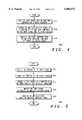
- FIG. 4shows a flow chart for a method of reducing distortion caused in a power amplifier in accordance with an embodiment of the present invention.
- FIG. 5shows a flow chart for a method of reducing distortion in an amplifier in accordance with a preferred embodiment of the present invention.
- the present inventionhelps solve the above-identified problems by providing a power amplifier circuit that amplifies the envelope of the input signal separately from the phase of the input signal, where the envelope of the output signal is provided as feedback into the circuit.
- FIG. 1shows a diagram of an amplifier circuit in accordance with a preferred embodiment of the present invention.
- Envelope elimination and restoration (EER)-type amplifierssuch as the one shown in FIG. 1 are recognized as high efficiency amplifiers.
- EERis a technique through which highly efficient but nonlinear radio frequency (RF) power amplifiers can be combined with other, highly efficient amplifiers to produce a high efficiency linear amplifier system.
- the detected envelopeis amplified efficiently by a class S or other highly efficient power amplifier which only has to operate on the bandwidth of the RF envelope.
- Amplitude modulation of the final RF power amplifierrestores the envelope to the phase modulated carrier creating an amplified replica of the input signal.
- EER-type amplifier 10includes power divider 210, envelope detector 220, difference amplifier 130, envelope amplifier 270, limiter 240, power amplifier 260, coupler 262, and envelope detector 120.
- EER-type amplifier 10receives an RF input into power divider 210.
- Power divider 210splits the RF input signal into an amplitude path which feeds envelope detector 220, and a phase path which feeds limiter 240.
- the phase path of EER-type amplifier 10includes limiter 240 and power amplifier 260.
- Limiter 240receives the signal output from power divider 210 and amplitude limits the signal.
- Limiter 240can be omitted, or can perform soft limiting, but limiter 240 preferably performs hard limiting so that the output of limiter 240 contains phase information with little or no amplitude information.
- the amplitude limited signal output from limiter 240is input to power amplifier 260.
- time delay elementfound in the phase path of most conventional EER-type amplifiers.
- the time delay elementnormally functions to balance the delay in the amplitude and phase paths. Because the preferred embodiment of the present invention provides other means to accomplish the delay matching, the time delay element may be advantageously omitted. This advantageous feature of the preferred embodiment is discussed further in connection with the amplitude path and the envelope amplifier below.
- the amplitude path of EER-type amplifier 10includes envelope detector 220, difference amplifier 130, and envelope amplifier 270.
- Envelope detector 220detects the envelope of the RF input signal and outputs an envelope signal which represents the amplitude information contained in the original RF input signal.
- Envelope detector 220is preferably a diode detector, however other types of detectors, such as a synchronous detector based upon a double balanced mixer, could be used.
- Difference amplifier 130receives the input envelope signal from envelope detector 220 and compares it to an output envelope signal generated by envelope detector 120.
- the output of difference amplifier 130is a slightly distorted version of the input envelope signal.
- the distortion introducedis preferably equal and opposite any distortion introduced by power amplifier 260.
- difference amplifier 130may scale either the input envelope signal, the output envelope signal, or both before amplifying the difference. In cases where it is advantageous to have nonlinear scaling of the envelope signals or of the difference signal, it can be performed by difference amplifier 130.
- Difference amplifier 130can be implemented in a variety of known ways, however it is preferably an operational amplifier.
- Envelope detector 120 and envelope detector 220are preferably matched so that they both introduce the same effects on the circuit. When both envelope detectors are matched, possible distortion introduced because of mismatch is reduced. Further, envelope detector 120 and envelope detector 220 are preferably located within the same package and are manufactured on the same substrate.
- Coupler 262is used to sample the output signal for the feedback. Of course, any means for sampling the output signal could be used in place of coupler 262 while still practicing the present invention. Coupler 262 takes a sample of the RF output waveform and feeds it back into the amplitude path through envelope detector 120. This feedback arrangement provides the well known benefits of feedback to an amplifier operating at very high frequency without the necessity of feeding back the very high frequency signals. The bandwidth requirements of the loop are dictated by the envelope bandwidth and not the RF bandwidth, so the benefits of the feedback can continue to be realized as the RF signals increase in frequency.
- Envelope amplifier 270amplifies the envelope signal output from difference amplifier 130 and drives the drain bias of power amplifier 260. Because envelope amplifier 270 only needs to operate on the bandwidth of the envelope rather than at the much higher RF bandwidth of the RF amplifier, envelope amplifier 270 can be an inexpensive and efficient amplifier with lower bandwidth requirements.
- envelope amplifier 270is a class S amplifier.
- Envelope amplifier 270amplifies the envelope signal to a level commensurate with the desired output.
- the output of the envelope amplifieris the power supply for RF power amplifier 260.
- the resultant remodulation of the phase modulated RF carrierrestores the envelope, producing an amplified replica of the input signal.
- FIG. 2shows a diagram of an envelope amplifier in accordance with a preferred embodiment of the present invention.
- Envelope amplifier 270includes difference amplifier 272, pulsewidth modulator (PWM) 275, driver 280, switching transistors 285, low pass filter 290, and voltage scaler 292.
- PWMpulsewidth modulator
- Difference amplifier 272receives the input to envelope amplifier 270 and compares it to a scaled version of the output of envelope amplifier 270.
- the scaled version of the output of envelope amplifier 270is produced by sampling the output of envelope amplifier 270 and scaling the resulting signal with voltage scaler 292. This signal path provides feedback within envelope amplifier 270.
- the sampling of the outputis preferably a direct connection, however sampling means that introduce less circuit loading are also suitable.
- Difference amplifier 272may scale either or both of its input signals before amplifying the difference. In cases where it is advantageous to have nonlinear scaling of the envelope signals or of the difference signal, it can be performed by difference amplifier 272. In the preferred embodiment as shown in FIG. 2, voltage scaler 292 scales the sampled output and difference amplifier 272 does not scale either of its input signals. Difference amplifier 272 can be implemented in a variety of known ways, however it is preferably an operational amplifier.
- PWM 275performs pulsewidth modulation of the envelope signal output from difference amplifier 272 to produce a pulsewidth modulated signal which has a duty cycle proportional to the amplitude of the envelope signal.
- the pulsewidth modulated signalis then fed to driver 280.
- Switching transistors 285 and low pass filter 290in response to driver 280, produce a signal that is an amplified version of the output of difference amplifier 272.
- the output of difference amplifier 272is input to PWM 275 rather than the envelope signal being directly input into PWM 275.
- the resulting feedbackcauses the output of envelope amplifier 270 to match very closely with the input of envelope amplifier 270, both in amplitude and phase.
- the output of low pass filter 290is delayed relative to the input of PWM 275, but it is not delayed relative to the input of envelope amplifier 270 because of the effects of the feedback.
- EER-type amplifiersexhibit a significant time delay in the envelope amplifier because of the delay introduced in the low pass filter following the pulsewidth modulator.
- the effects of the delay introduced by low pass filter 290have been removed by the feedback.
- the importance of the lack of delay in envelope amplifier 270becomes apparent when viewing EER-type amplifier 10 as a whole.
- conventional EER-type amplifiersinclude a delay element in the phase path to match the delay in the envelope amplifier low pass filter. Often this delay must be matched very closely and can therefore represent a significant expense.
- the removal of the delay in the amplitude path as in the preferred embodiment exemplified hereinallows the removal of the delay in the phase path resulting in cost savings and decreased circuit complexity.
- the combined circuit of FIG. 1 and FIG. 2forms an EER-type amplifier with two feedback loops, one embedded within the other.
- the closed loop envelope amplifier shown in FIG. 2forms the inner feedback loop.
- the outer feedback loopis formed by detection of the restored envelope at the output of the EER-type amplifier.
- the detected envelope at the outputis compared to the RF input envelope using a difference amplifier to generate a new signal to drive the envelope amplifier.
- This new signalcontains the distortion necessary to make the input and output envelopes nearly identical to reduce distortion in the amplification process.
- FIG. 3shows a diagram of a communications device in accordance with a preferred embodiment of the present invention.
- Communications device 300includes power amplifier circuit 320 and antenna 310.
- Power amplifier circuit 320may be any of the low distortion amplifiers of the present invention, including for example, EER-type amplifier 10 (FIG. 1).
- Communications device 300may be one of many different devices capable of communications. Examples include, but are not limited to, individual subscriber units in a satellite communications system, amateur radios, business band radios, two way pagers, and cellular phones.
- FIG. 4shows a flowchart for a method of reducing distortion caused in a power amplifier in accordance with an embodiment of the present invention.
- Method 400begins with step 410, in which an input signal is split into an amplitude component and a phase component. After step 410, the amplitude component and the phase component of the input signal can each be modified without affecting the other.
- an amplified envelope signalis produced as a function of the amplitude component of the input signal and of the output signal.
- an envelope detected version of the output signalis fed back into the amplitude path.
- the resulting amplified envelope signalcontains information from the input envelope as well as the output envelope. Because the amplified envelope signal contains information from the output signal, the amplified envelope signal is predistorted in such a way as to decrease the effects of distortion caused in the amplifier chain following the amplified envelope signal.
- the amplified envelope signalis produced as a difference between the input envelope and the output envelope. This function is exemplified by difference amplifier 130 (FIG. 1).
- step 430modulates the phase component with the amplified envelope signal to produce the output signal.
- This modulationcan be performed by modulating the drain of a field effect transistor (FET) amplifier.
- FETfield effect transistor
- the amplified envelope signalfunctions as the power supply of the final RF amplifier.
- the output signalis a more faithful reproduction of the input signal than could otherwise be obtained by conventional methods.
- FIG. 5shows a flowchart for a method of reducing distortion in an amplifier in accordance with a preferred embodiment of the present invention.
- step 510the envelope of the input signal is detected producing an input envelope signal.
- step 520the envelope of the output signal is sampled producing an output envelope signal.
- a first signalis produced in step 530 as a function of the two envelope signals.
- This first signalis analogous to an "error" signal in a conventional feedback system because it contains information from both the input and the output.
- the output envelope signalis scaled and then the first signal is produced by taking the difference between the input envelope signal and the scaled output envelope signal.
- the first signalis amplified to produce an amplified envelope signal.
- An example of an amplifier that amplifies the first signalis shown as envelope amplifier 270 (FIG. 2).
- the amplifierpreferably contains a feedback loop. The output of the amplifier is fed back to the input of the amplifier after being scaled. The scaled output is then compared to the first signal, producing a second signal which is then amplified with a class S amplifier.
- the class S amplifiergenerates a pulsewidth modulated signal having a duty cycle proportional to the second signal, and then the pulsewidth modulated signal is low pass filtered to produce the amplified envelope signal.
- step 550an amplifier stage is modulated with the amplified envelope signal.
- the output signalis a more faithful reproduction of the input signal than could otherwise be obtained by conventional methods.
- the method and apparatus of the present inventionprovide a means for operating a saturating amplifier at full power with acceptably low intermodulation products.
- the method and apparatus of the present invention as describedrepresent a versatile way of achieving low distortion in a high efficiency, linear power amplifier. Highly efficient linear amplifiers with low distortion are very useful in the amplification of modulated signals which contain information in both amplitude and phase. Communications devices, which often transmit signals having information in both amplitude and phase, benefit greatly from the apparatus and method of the present invention. Low distortion allows the communications devices to communicate more reliably and high efficiency allows the devices to operate longer on a single battery.
- coupler 262 and envelope detector 120could be combined into a single function, or power amplifier 260 could be comprised of many amplifier stages.
Landscapes
- Engineering & Computer Science (AREA)
- Power Engineering (AREA)
- Amplifiers (AREA)
Abstract
Description
Claims (11)
Priority Applications (11)
| Application Number | Priority Date | Filing Date | Title |
|---|---|---|---|
| US08/900,584US5886572A (en) | 1997-07-25 | 1997-07-25 | Method and apparatus for reducing distortion in a power amplifier |
| PCT/US1998/008556WO1999005783A1 (en) | 1997-07-25 | 1998-04-28 | Low distortion power amplifier |
| GB9905805AGB2331881B (en) | 1997-07-25 | 1998-04-28 | Low distortion power amplifier |
| CA002266739ACA2266739A1 (en) | 1997-07-25 | 1998-04-28 | Low distortion power amplifier |
| FI990600AFI990600A0 (en) | 1997-07-25 | 1998-04-28 | Low distortion power amplifier |
| JP50977999AJP2002500846A (en) | 1997-07-25 | 1998-04-28 | Low distortion power amplifier |
| DE19881110TDE19881110T1 (en) | 1997-07-25 | 1998-04-28 | Low distortion power amplifier |
| CN98801051.8ACN1234922A (en) | 1997-07-25 | 1998-04-28 | Low distortion power amplifier |
| TW087110975ATW432781B (en) | 1997-07-25 | 1998-07-07 | Method and apparatus for reducing distortion in a power amplifier |
| FR9809469AFR2766637B1 (en) | 1997-07-25 | 1998-07-24 | METHOD AND APPARATUS FOR REDUCING DISTORTION IN A POWER AMPLIFIER |
| SE9901094ASE523585C2 (en) | 1997-07-25 | 1999-03-25 | Low distortion power amplifier |
Applications Claiming Priority (1)
| Application Number | Priority Date | Filing Date | Title |
|---|---|---|---|
| US08/900,584US5886572A (en) | 1997-07-25 | 1997-07-25 | Method and apparatus for reducing distortion in a power amplifier |
Publications (1)
| Publication Number | Publication Date |
|---|---|
| US5886572Atrue US5886572A (en) | 1999-03-23 |
Family
ID=25412754
Family Applications (1)
| Application Number | Title | Priority Date | Filing Date |
|---|---|---|---|
| US08/900,584Expired - LifetimeUS5886572A (en) | 1997-07-25 | 1997-07-25 | Method and apparatus for reducing distortion in a power amplifier |
Country Status (11)
| Country | Link |
|---|---|
| US (1) | US5886572A (en) |
| JP (1) | JP2002500846A (en) |
| CN (1) | CN1234922A (en) |
| CA (1) | CA2266739A1 (en) |
| DE (1) | DE19881110T1 (en) |
| FI (1) | FI990600A0 (en) |
| FR (1) | FR2766637B1 (en) |
| GB (1) | GB2331881B (en) |
| SE (1) | SE523585C2 (en) |
| TW (1) | TW432781B (en) |
| WO (1) | WO1999005783A1 (en) |
Cited By (48)
| Publication number | Priority date | Publication date | Assignee | Title |
|---|---|---|---|---|
| US6112062A (en)* | 1997-09-26 | 2000-08-29 | The Whitaker Corporation | Predistortion for high power amplifiers |
| US6157253A (en)* | 1999-09-03 | 2000-12-05 | Motorola, Inc. | High efficiency power amplifier circuit with wide dynamic backoff range |
| US6194963B1 (en)* | 1998-11-18 | 2001-02-27 | Ericsson Inc. | Circuit and method for I/Q modulation with independent, high efficiency amplitude modulation |
| US6252455B1 (en) | 1999-10-07 | 2001-06-26 | Motorola, Inc. | Method and apparatus for efficient signal amplification |
| US6307436B1 (en) | 1999-06-15 | 2001-10-23 | Nec Corporation | Predistortion type linearizer with a resonant circuit and common gate FET |
| US6359504B1 (en)* | 2000-01-28 | 2002-03-19 | Lucent Technologies Inc. | Power amplifier using upstream signal information |
| US6366177B1 (en) | 2000-02-02 | 2002-04-02 | Tropian Inc. | High-efficiency power modulators |
| US6377784B2 (en) | 1999-02-09 | 2002-04-23 | Tropian, Inc. | High-efficiency modulation RF amplifier |
| US6407634B1 (en)* | 2000-06-16 | 2002-06-18 | Motorola, Inc. | Linear envelope tracking RF power amplifier with adaptive analog signal processing |
| US6445249B1 (en)* | 2001-08-08 | 2002-09-03 | Motorola, Inc. | Modification of phase component of error signal to reduce variation of phase component of output signal of power amplifier |
| US6492868B2 (en) | 2000-08-14 | 2002-12-10 | Larry Kirn | Dynamic range enhancement technique |
| US6509793B2 (en) | 2000-05-19 | 2003-01-21 | Larry Kim | Switching amplifier resolution enhancement apparatus and methods |
| US6535058B1 (en) | 1998-11-12 | 2003-03-18 | Jam Technologies, Llc | Multi-reference, high-accuracy switching amplifier |
| US20030112068A1 (en)* | 2000-02-24 | 2003-06-19 | Peter Kenington | Amplifier |
| US6593812B2 (en) | 2001-04-23 | 2003-07-15 | Telefonaktiebolaget Lm Ericsson | Automatic optimization of linearity for envelope feedback RF amplifier linearization |
| US6600369B2 (en)* | 2001-12-07 | 2003-07-29 | Motorola, Inc. | Wideband linear amplifier with predistortion error correction |
| US20030151456A1 (en)* | 1998-11-12 | 2003-08-14 | Larry Kirn | Multi-reference high accuracy switching amplifier expansion |
| FR2837639A1 (en)* | 2002-03-25 | 2003-09-26 | Canon Kk | Wireless transmitter having reduced power consumption, comprises a modulator including digital and analog parts |
| FR2837647A1 (en)* | 2002-03-25 | 2003-09-26 | Canon Kk | Wireless transmitter having reduced power consumption, comprises a modulator including digital and analog parts |
| EP1096670A3 (en)* | 1999-10-08 | 2003-10-29 | M/A-Com Eurotec | System and method for transmitting digital information using interleaved delta modulation |
| WO2004010283A1 (en)* | 2002-07-24 | 2004-01-29 | Motorola, Inc. | Method and apparatus for providing a supply voltage based on an envelope of a radio frequency signal |
| US6707857B1 (en) | 2000-07-14 | 2004-03-16 | Ericsson Inc. | Reference signal pre-distortion for transmitter with frequency synthesizer based phase encoding |
| US20040108896A1 (en)* | 2002-09-17 | 2004-06-10 | Jacob Midtgaard | Envelope elimination and restoration linear amplifier |
| US6771120B2 (en) | 2000-08-14 | 2004-08-03 | Jam Technologies, Llc | Reference generation technique for multiple-reference amplifier |
| US20040166813A1 (en)* | 2001-02-23 | 2004-08-26 | Mann Stephen Ian | Cartesian loop systems with digital processing |
| US20040185809A1 (en)* | 2001-07-03 | 2004-09-23 | Roland Jenkins | Method for adjusting the amplification of a high frequency signal |
| US6813319B1 (en) | 1999-10-08 | 2004-11-02 | M/A-Com Eurotec | System and method for transmitting digital information using interleaved delta modulation |
| US6839549B2 (en) | 2000-12-14 | 2005-01-04 | Ericsson Inc. | System and method of RF power amplification |
| US6864668B1 (en) | 1999-02-09 | 2005-03-08 | Tropian, Inc. | High-efficiency amplifier output level and burst control |
| US6937090B2 (en) | 2000-08-28 | 2005-08-30 | Jam Technologies, Llc | Charge injection reduction technique in single and multi-reference switching amplifiers |
| US20050208911A1 (en)* | 2002-03-02 | 2005-09-22 | Leif Petersen | Amplifier circuits and their use in radio frequency transmitters |
| US6975686B1 (en) | 2000-10-31 | 2005-12-13 | Telefonaktiebolaget L.M. Ericsson | IQ modulation systems and methods that use separate phase and amplitude signal paths |
| US7002322B1 (en)* | 2003-12-23 | 2006-02-21 | Nortel Networks Limited | Modulated power supply |
| US20070018718A1 (en)* | 2005-06-20 | 2007-01-25 | National Sun Yat-Sen University | Microwave transmitter and the method for increasing envelope bandwidth |
| US20070249304A1 (en)* | 2005-03-25 | 2007-10-25 | Pulsewave Rf, Inc. | Radio frequency power amplifier and method using a controlled supply |
| KR100815381B1 (en) | 2005-12-27 | 2008-03-20 | 후지쯔 가부시끼가이샤 | Timing controller and timing control method |
| US20100194440A1 (en)* | 2006-02-03 | 2010-08-05 | Quantance, Inc. | Phase Error De-Glitching Circuit and Method of Operating |
| US7791413B2 (en) | 2008-06-05 | 2010-09-07 | Her Majesty The Queen In Right Of Canada | Linearizing technique for power amplifiers |
| US20110140777A1 (en)* | 2006-02-03 | 2011-06-16 | Quantance, Inc. | RF Power Amplifier Controller Circuit Including Calibrated Phase Control Loop |
| US20110189966A1 (en)* | 2006-02-03 | 2011-08-04 | Quantance, Inc. | Power Amplifier Controller Circuit |
| US8238853B2 (en) | 2006-02-03 | 2012-08-07 | Quantance, Inc. | Amplitude error de-glitching circuit and method of operating |
| US8742844B2 (en) | 2012-02-17 | 2014-06-03 | Kabushiki Kaisha Toshiba | Power amplifier device |
| US8749308B2 (en) | 2003-02-19 | 2014-06-10 | Nujira Limited | High efficiency amplification |
| US20150123735A1 (en)* | 2013-10-21 | 2015-05-07 | Nujira Limited | Reduced bandwith of signal in an envelope path for envelope tracking system |
| US20150162882A1 (en)* | 2013-12-09 | 2015-06-11 | Marvell World Trade Ltd. | Power amplifier with wide band am-am feedback and digital pre-distortion |
| US20180054172A1 (en)* | 2015-07-27 | 2018-02-22 | Skyworks Solutions, Inc. | Devices and methods related to adjusting power provided to power amplifiers |
| US10396713B2 (en)* | 2017-05-26 | 2019-08-27 | Samsung Electro-Mechanics Co., Ltd. | Envelope-tracking current bias circuit with offset cancellation function |
| US11283479B2 (en)* | 2020-06-18 | 2022-03-22 | Analog Devices, Inc. | Apparatus and methods for radio frequency signal limiting |
Families Citing this family (21)
| Publication number | Priority date | Publication date | Assignee | Title |
|---|---|---|---|---|
| NZ338097A (en)* | 1999-09-29 | 2001-05-25 | Tait Electronics Ltd | Digitally controlled envelope elimination and restoration phase lock loop radio frequency amplifier |
| GB2359681B (en) | 2000-02-25 | 2004-03-10 | Wireless Systems Int Ltd | Switched amplifier |
| US6785521B2 (en) | 2001-03-21 | 2004-08-31 | Ericsson Inc. | System and method for current-mode amplitude modulation |
| US6738432B2 (en) | 2001-03-21 | 2004-05-18 | Ericsson Inc. | System and method for RF signal amplification |
| GB2380880B (en) | 2001-10-10 | 2004-02-11 | Zarlink Semiconductor Ltd | A polar loop transmitter |
| DE10230919B4 (en) | 2002-07-09 | 2018-08-02 | Rohde & Schwarz Gmbh & Co. Kg | Radio frequency transmitter and method for efficiency-optimized operation of the radio-frequency transmitter |
| DE10250613B4 (en)* | 2002-10-30 | 2007-02-08 | Advanced Micro Devices, Inc., Sunnyvale | Integrated RF signal level detector usable for automatic power level control |
| JP3841416B2 (en)* | 2003-10-07 | 2006-11-01 | 松下電器産業株式会社 | Transmission device, transmission output control method, and wireless communication device |
| JP4199185B2 (en)* | 2004-03-01 | 2008-12-17 | パナソニック株式会社 | Transmitting apparatus and wireless communication apparatus |
| JP4536468B2 (en)* | 2004-09-21 | 2010-09-01 | パナソニック株式会社 | Class E amplifier and EER modulation amplifier |
| CN101401261B (en) | 2006-02-03 | 2012-11-21 | 匡坦斯公司 | Power amplifier controller circuit |
| US8095090B2 (en)* | 2006-02-03 | 2012-01-10 | Quantance, Inc. | RF power amplifier controller circuit |
| US8093946B2 (en) | 2006-03-17 | 2012-01-10 | Nujira Limited | Joint optimisation of supply and bias modulation |
| CN101442294B (en)* | 2007-11-23 | 2011-11-09 | 瑞昱半导体股份有限公司 | Amplifying circuit and method for improving linearity thereof |
| GB2495306B (en) | 2011-10-05 | 2015-06-24 | Nujira Ltd | Envelope tracking push-pull or differential power amplifier |
| WO2013136860A1 (en)* | 2012-03-12 | 2013-09-19 | 日本電気株式会社 | Transmission apparatus and transmission method |
| CN104836574B (en)* | 2015-04-30 | 2018-03-30 | 中国科学院微电子研究所 | Envelope tracking power amplifier structure capable of automatically aligning |
| CN104836536B (en)* | 2015-04-30 | 2018-09-04 | 中国科学院微电子研究所 | Power amplifier structure based on negative feedback |
| US10505498B2 (en)* | 2017-10-24 | 2019-12-10 | Samsung Electro-Mechanics Co., Ltd. | Envelope tracking bias circuit and power amplifying device |
| KR102029554B1 (en)* | 2017-10-24 | 2019-10-07 | 삼성전기주식회사 | Envelope bias circuit and power amplifying apparatus |
| CN109813952A (en)* | 2018-12-12 | 2019-05-28 | 珠海亿智电子科技有限公司 | A kind of envelope detected circuit |
Citations (10)
| Publication number | Priority date | Publication date | Assignee | Title |
|---|---|---|---|---|
| GB226456A (en)* | 1924-08-16 | 1924-12-24 | Eric Vilhelm Larson | Improvements in separator bowls |
| US4210874A (en)* | 1978-10-23 | 1980-07-01 | Raytheon Company | Gain control amplifier circuit |
| US4831334A (en)* | 1987-06-08 | 1989-05-16 | Hughes Aircraft Company | Envelope amplifier |
| US5101172A (en)* | 1989-12-26 | 1992-03-31 | Mitsubishi Denki Kabushiki Kaisha | Linear amplifier |
| US5105164A (en)* | 1989-02-28 | 1992-04-14 | At&T Bell Laboratories | High efficiency uhf linear power amplifier |
| US5115205A (en)* | 1990-12-28 | 1992-05-19 | Square D Company | AC amplifier with automatic DC compensation |
| US5124665A (en)* | 1990-02-08 | 1992-06-23 | The Marconi Company Limited | Circuit for reducing distortion produced by an r.f. power amplifier |
| US5138274A (en)* | 1990-06-06 | 1992-08-11 | Oki Electric Industry Co., Ltd. | Linear amplifier circuit |
| US5251330A (en)* | 1989-06-30 | 1993-10-05 | Nippon Telegraph & Telephone Corporation | Linear transmitter |
| US5610553A (en)* | 1993-03-02 | 1997-03-11 | Kirn; Larry | Switching amplifier with impedance transformation output stage |
Family Cites Families (2)
| Publication number | Priority date | Publication date | Assignee | Title |
|---|---|---|---|---|
| NL8203428A (en)* | 1982-09-02 | 1984-04-02 | Philips Nv | DEVICE FOR CONVERTING AN ELECTRIC SIGNAL TO AN ACOUSTIC SIGNAL. |
| US5847602A (en)* | 1997-03-03 | 1998-12-08 | Hewlett-Packard Company | Method and apparatus for linearizing an efficient class D/E power amplifier using delta modulation |
- 1997
- 1997-07-25USUS08/900,584patent/US5886572A/ennot_activeExpired - Lifetime
- 1998
- 1998-04-28GBGB9905805Apatent/GB2331881B/ennot_activeExpired - Fee Related
- 1998-04-28CACA002266739Apatent/CA2266739A1/ennot_activeAbandoned
- 1998-04-28WOPCT/US1998/008556patent/WO1999005783A1/enactiveApplication Filing
- 1998-04-28FIFI990600Apatent/FI990600A0/enunknown
- 1998-04-28JPJP50977999Apatent/JP2002500846A/ennot_activeCeased
- 1998-04-28CNCN98801051.8Apatent/CN1234922A/enactivePending
- 1998-04-28DEDE19881110Tpatent/DE19881110T1/ennot_activeWithdrawn
- 1998-07-07TWTW087110975Apatent/TW432781B/enactive
- 1998-07-24FRFR9809469Apatent/FR2766637B1/ennot_activeExpired - Fee Related
- 1999
- 1999-03-25SESE9901094Apatent/SE523585C2/ennot_activeIP Right Cessation
Patent Citations (10)
| Publication number | Priority date | Publication date | Assignee | Title |
|---|---|---|---|---|
| GB226456A (en)* | 1924-08-16 | 1924-12-24 | Eric Vilhelm Larson | Improvements in separator bowls |
| US4210874A (en)* | 1978-10-23 | 1980-07-01 | Raytheon Company | Gain control amplifier circuit |
| US4831334A (en)* | 1987-06-08 | 1989-05-16 | Hughes Aircraft Company | Envelope amplifier |
| US5105164A (en)* | 1989-02-28 | 1992-04-14 | At&T Bell Laboratories | High efficiency uhf linear power amplifier |
| US5251330A (en)* | 1989-06-30 | 1993-10-05 | Nippon Telegraph & Telephone Corporation | Linear transmitter |
| US5101172A (en)* | 1989-12-26 | 1992-03-31 | Mitsubishi Denki Kabushiki Kaisha | Linear amplifier |
| US5124665A (en)* | 1990-02-08 | 1992-06-23 | The Marconi Company Limited | Circuit for reducing distortion produced by an r.f. power amplifier |
| US5138274A (en)* | 1990-06-06 | 1992-08-11 | Oki Electric Industry Co., Ltd. | Linear amplifier circuit |
| US5115205A (en)* | 1990-12-28 | 1992-05-19 | Square D Company | AC amplifier with automatic DC compensation |
| US5610553A (en)* | 1993-03-02 | 1997-03-11 | Kirn; Larry | Switching amplifier with impedance transformation output stage |
Non-Patent Citations (4)
| Title |
|---|
| An article entitled "Single-Sideband Transmission By Envelope Elimination And Restoration" by Leonard R. Kahn from Proceeding of the I.R.E., 1952. |
| An article entitled Single Sideband Transmission By Envelope Elimination And Restoration by Leonard R. Kahn from Proceeding of the I.R.E., 1952.* |
| Publication entitled, "A High Efficiency 835 MHZ Linear Power Amplifier For Digital Cellular Telephony", M.J. Koch et al. Published by Gateway to New Concepts in Vehicular Technology, San Francisco May 1-3, 1989. |
| Publication entitled, A High Efficiency 835 MHZ Linear Power Amplifier For Digital Cellular Telephony , M.J. Koch et al. Published by Gateway to New Concepts in Vehicular Technology, San Francisco May 1 3, 1989.* |
Cited By (66)
| Publication number | Priority date | Publication date | Assignee | Title |
|---|---|---|---|---|
| US6112062A (en)* | 1997-09-26 | 2000-08-29 | The Whitaker Corporation | Predistortion for high power amplifiers |
| US20030151456A1 (en)* | 1998-11-12 | 2003-08-14 | Larry Kirn | Multi-reference high accuracy switching amplifier expansion |
| US6768375B2 (en) | 1998-11-12 | 2004-07-27 | Jam Technologies, Llc | Multi-reference high accuracy switching amplifier expansion |
| US6535058B1 (en) | 1998-11-12 | 2003-03-18 | Jam Technologies, Llc | Multi-reference, high-accuracy switching amplifier |
| US6194963B1 (en)* | 1998-11-18 | 2001-02-27 | Ericsson Inc. | Circuit and method for I/Q modulation with independent, high efficiency amplitude modulation |
| US6864668B1 (en) | 1999-02-09 | 2005-03-08 | Tropian, Inc. | High-efficiency amplifier output level and burst control |
| US6377784B2 (en) | 1999-02-09 | 2002-04-23 | Tropian, Inc. | High-efficiency modulation RF amplifier |
| US6307436B1 (en) | 1999-06-15 | 2001-10-23 | Nec Corporation | Predistortion type linearizer with a resonant circuit and common gate FET |
| US6157253A (en)* | 1999-09-03 | 2000-12-05 | Motorola, Inc. | High efficiency power amplifier circuit with wide dynamic backoff range |
| US6252455B1 (en) | 1999-10-07 | 2001-06-26 | Motorola, Inc. | Method and apparatus for efficient signal amplification |
| US6813319B1 (en) | 1999-10-08 | 2004-11-02 | M/A-Com Eurotec | System and method for transmitting digital information using interleaved delta modulation |
| EP1096670A3 (en)* | 1999-10-08 | 2003-10-29 | M/A-Com Eurotec | System and method for transmitting digital information using interleaved delta modulation |
| US6359504B1 (en)* | 2000-01-28 | 2002-03-19 | Lucent Technologies Inc. | Power amplifier using upstream signal information |
| US6366177B1 (en) | 2000-02-02 | 2002-04-02 | Tropian Inc. | High-efficiency power modulators |
| US6847259B2 (en)* | 2000-02-24 | 2005-01-25 | Andrew Corporation | Amplifier |
| US20030112068A1 (en)* | 2000-02-24 | 2003-06-19 | Peter Kenington | Amplifier |
| US6509793B2 (en) | 2000-05-19 | 2003-01-21 | Larry Kim | Switching amplifier resolution enhancement apparatus and methods |
| US6617920B2 (en) | 2000-06-16 | 2003-09-09 | Motorola, Inc. | Linear envelope tracking RF power amplifier with adaptive analog signal processing |
| US6407634B1 (en)* | 2000-06-16 | 2002-06-18 | Motorola, Inc. | Linear envelope tracking RF power amplifier with adaptive analog signal processing |
| US6707857B1 (en) | 2000-07-14 | 2004-03-16 | Ericsson Inc. | Reference signal pre-distortion for transmitter with frequency synthesizer based phase encoding |
| US6492868B2 (en) | 2000-08-14 | 2002-12-10 | Larry Kirn | Dynamic range enhancement technique |
| US6771120B2 (en) | 2000-08-14 | 2004-08-03 | Jam Technologies, Llc | Reference generation technique for multiple-reference amplifier |
| US6937090B2 (en) | 2000-08-28 | 2005-08-30 | Jam Technologies, Llc | Charge injection reduction technique in single and multi-reference switching amplifiers |
| US7072421B2 (en) | 2000-10-31 | 2006-07-04 | Telefonaktiebolaget L.M. Ericsson | IQ modulation systems and methods that use separate phase and amplitude signal paths and perform modulation within a phase locked loop |
| US6975686B1 (en) | 2000-10-31 | 2005-12-13 | Telefonaktiebolaget L.M. Ericsson | IQ modulation systems and methods that use separate phase and amplitude signal paths |
| US6839549B2 (en) | 2000-12-14 | 2005-01-04 | Ericsson Inc. | System and method of RF power amplification |
| US20040166813A1 (en)* | 2001-02-23 | 2004-08-26 | Mann Stephen Ian | Cartesian loop systems with digital processing |
| US6593812B2 (en) | 2001-04-23 | 2003-07-15 | Telefonaktiebolaget Lm Ericsson | Automatic optimization of linearity for envelope feedback RF amplifier linearization |
| US7386287B2 (en) | 2001-07-03 | 2008-06-10 | Siemens Aktiengesellschaft | Method for controlling the gain of radio-frequency signal |
| US20040185809A1 (en)* | 2001-07-03 | 2004-09-23 | Roland Jenkins | Method for adjusting the amplification of a high frequency signal |
| US6445249B1 (en)* | 2001-08-08 | 2002-09-03 | Motorola, Inc. | Modification of phase component of error signal to reduce variation of phase component of output signal of power amplifier |
| US6600369B2 (en)* | 2001-12-07 | 2003-07-29 | Motorola, Inc. | Wideband linear amplifier with predistortion error correction |
| US20050208911A1 (en)* | 2002-03-02 | 2005-09-22 | Leif Petersen | Amplifier circuits and their use in radio frequency transmitters |
| US7206356B2 (en) | 2002-03-25 | 2007-04-17 | Canon Kabushiki Kaisha | Wireless transmitter with reduced power consumption |
| FR2837647A1 (en)* | 2002-03-25 | 2003-09-26 | Canon Kk | Wireless transmitter having reduced power consumption, comprises a modulator including digital and analog parts |
| US20030232607A1 (en)* | 2002-03-25 | 2003-12-18 | Canon Kabushiki Kaisha | Wireless transmitter with reduced power consumption |
| FR2837639A1 (en)* | 2002-03-25 | 2003-09-26 | Canon Kk | Wireless transmitter having reduced power consumption, comprises a modulator including digital and analog parts |
| US6696866B2 (en)* | 2002-07-24 | 2004-02-24 | Motorola, Inc. | Method and apparatus for providing a supply voltage based on an envelope of a radio frequency signal |
| WO2004010283A1 (en)* | 2002-07-24 | 2004-01-29 | Motorola, Inc. | Method and apparatus for providing a supply voltage based on an envelope of a radio frequency signal |
| US7049887B2 (en)* | 2002-09-17 | 2006-05-23 | Nokia Corporation | Envelope elimination and restoration linear amplifier |
| US20040108896A1 (en)* | 2002-09-17 | 2004-06-10 | Jacob Midtgaard | Envelope elimination and restoration linear amplifier |
| US9641132B2 (en) | 2003-02-19 | 2017-05-02 | Snaptrack, Inc. | High efficiency amplification |
| US9190958B2 (en) | 2003-02-19 | 2015-11-17 | Snaptrack, Inc. | High efficiency amplification |
| US8749308B2 (en) | 2003-02-19 | 2014-06-10 | Nujira Limited | High efficiency amplification |
| US9118278B2 (en) | 2003-02-19 | 2015-08-25 | Snaptrack, Inc. | High efficiency amplification |
| US7002322B1 (en)* | 2003-12-23 | 2006-02-21 | Nortel Networks Limited | Modulated power supply |
| US20070249304A1 (en)* | 2005-03-25 | 2007-10-25 | Pulsewave Rf, Inc. | Radio frequency power amplifier and method using a controlled supply |
| US7474149B2 (en) | 2005-03-25 | 2009-01-06 | Pulsewave Rf, Inc. | Radio frequency power amplifier and method using a controlled supply |
| US20070018718A1 (en)* | 2005-06-20 | 2007-01-25 | National Sun Yat-Sen University | Microwave transmitter and the method for increasing envelope bandwidth |
| KR100815381B1 (en) | 2005-12-27 | 2008-03-20 | 후지쯔 가부시끼가이샤 | Timing controller and timing control method |
| US8238853B2 (en) | 2006-02-03 | 2012-08-07 | Quantance, Inc. | Amplitude error de-glitching circuit and method of operating |
| US20110189966A1 (en)* | 2006-02-03 | 2011-08-04 | Quantance, Inc. | Power Amplifier Controller Circuit |
| US8260225B2 (en) | 2006-02-03 | 2012-09-04 | Quantance, Inc. | Power amplifier controller circuit |
| US8340604B2 (en) | 2006-02-03 | 2012-12-25 | Quantance, Inc. | RF power amplifier controller circuit including calibrated phase control loop |
| US20100194440A1 (en)* | 2006-02-03 | 2010-08-05 | Quantance, Inc. | Phase Error De-Glitching Circuit and Method of Operating |
| US20110140777A1 (en)* | 2006-02-03 | 2011-06-16 | Quantance, Inc. | RF Power Amplifier Controller Circuit Including Calibrated Phase Control Loop |
| US8179994B2 (en) | 2006-02-03 | 2012-05-15 | Quantance, Inc. | Phase error de-glitching circuit and method of operating |
| US7791413B2 (en) | 2008-06-05 | 2010-09-07 | Her Majesty The Queen In Right Of Canada | Linearizing technique for power amplifiers |
| US8742844B2 (en) | 2012-02-17 | 2014-06-03 | Kabushiki Kaisha Toshiba | Power amplifier device |
| US9350302B2 (en)* | 2013-10-21 | 2016-05-24 | Snaptrack, Inc. | Reduced bandwith of signal in an envelope path for envelope tracking system |
| US20150123735A1 (en)* | 2013-10-21 | 2015-05-07 | Nujira Limited | Reduced bandwith of signal in an envelope path for envelope tracking system |
| US20150162882A1 (en)* | 2013-12-09 | 2015-06-11 | Marvell World Trade Ltd. | Power amplifier with wide band am-am feedback and digital pre-distortion |
| US9385666B2 (en)* | 2013-12-09 | 2016-07-05 | Marvell World Trade Ltd. | Power amplifier with wide band AM-AM feedback and digital pre-distortion |
| US20180054172A1 (en)* | 2015-07-27 | 2018-02-22 | Skyworks Solutions, Inc. | Devices and methods related to adjusting power provided to power amplifiers |
| US10396713B2 (en)* | 2017-05-26 | 2019-08-27 | Samsung Electro-Mechanics Co., Ltd. | Envelope-tracking current bias circuit with offset cancellation function |
| US11283479B2 (en)* | 2020-06-18 | 2022-03-22 | Analog Devices, Inc. | Apparatus and methods for radio frequency signal limiting |
Also Published As
| Publication number | Publication date |
|---|---|
| TW432781B (en) | 2001-05-01 |
| FI990600L (en) | 1999-03-17 |
| CN1234922A (en) | 1999-11-10 |
| FI990600A7 (en) | 1999-03-17 |
| FR2766637B1 (en) | 2002-10-25 |
| DE19881110T1 (en) | 1999-08-05 |
| SE9901094D0 (en) | 1999-03-25 |
| WO1999005783A1 (en) | 1999-02-04 |
| SE9901094L (en) | 1999-03-25 |
| FR2766637A1 (en) | 1999-01-29 |
| FI990600A0 (en) | 1999-03-17 |
| GB2331881A (en) | 1999-06-02 |
| GB2331881B (en) | 2002-03-20 |
| CA2266739A1 (en) | 1999-02-04 |
| SE523585C2 (en) | 2004-05-04 |
| GB9905805D0 (en) | 1999-05-05 |
| JP2002500846A (en) | 2002-01-08 |
Similar Documents
| Publication | Publication Date | Title |
|---|---|---|
| US5886572A (en) | Method and apparatus for reducing distortion in a power amplifier | |
| US5861777A (en) | Method and apparatus for compensation of phase distortion in power amplifiers | |
| US5936464A (en) | Method and apparatus for reducing distortion in a high efficiency power amplifier | |
| US6084468A (en) | Method and apparatus for high efficiency wideband power amplification | |
| US6252455B1 (en) | Method and apparatus for efficient signal amplification | |
| US6130910A (en) | Method and apparatus for high efficiency wideband power amplification | |
| KR0135750B1 (en) | High Efficiency UHF Linear Power Amplifier | |
| US5942938A (en) | Method and apparatus for high efficiency power amplification | |
| US7560984B2 (en) | Transmitter | |
| US5831475A (en) | Method and apparatus for delay matching in a power amplifier | |
| US7062236B2 (en) | Transmitter circuits | |
| US6590940B1 (en) | Power modulation systems and methods that separately amplify low and high frequency portions of an amplitude waveform | |
| US7742541B2 (en) | Transmission circuit, and communication apparatus using the same | |
| US7932790B2 (en) | Switched modulation of a radio-frequency amplifier | |
| US7620377B2 (en) | Bandwidth enhancement for envelope elimination and restoration transmission systems | |
| US7583940B2 (en) | Transmission circuit and communication apparatus employing the same | |
| US5990735A (en) | Method and apparatus for high efficiency power amplification | |
| AU782014B2 (en) | Improvements relating to EER transmitters | |
| US8300728B1 (en) | Complex envelope elimination and restoration transmitter | |
| US6822523B2 (en) | Power modulator and method of operating a power modulator | |
| US7391261B2 (en) | Enhanced bandwidth envelope elimination and restoration | |
| US6100756A (en) | Method and apparatus for high efficiency power amplification | |
| US6049248A (en) | Method and apparatus for generating a driver signal for use by a non-linear class S amplifier for producing linear amplification | |
| US7050770B1 (en) | Linearized amplifier having a bypass circuit | |
| US12231143B2 (en) | Radio transmitter providing an analog signal with both radio frequency and baseband frequency information |
Legal Events
| Date | Code | Title | Description |
|---|---|---|---|
| AS | Assignment | Owner name:MOTOROLA, INC., ILLINOIS Free format text:ASSIGNMENT OF ASSIGNORS INTEREST;ASSIGNORS:MYERS, RONALD GENE;SIGMON, BERNARD EUGENE;JACKSON, ROBERT MICHAEL;REEL/FRAME:008737/0447 Effective date:19970718 | |
| STCF | Information on status: patent grant | Free format text:PATENTED CASE | |
| FPAY | Fee payment | Year of fee payment:4 | |
| FPAY | Fee payment | Year of fee payment:8 | |
| FPAY | Fee payment | Year of fee payment:12 | |
| AS | Assignment | Owner name:MOTOROLA MOBILITY, INC, ILLINOIS Free format text:ASSIGNMENT OF ASSIGNORS INTEREST;ASSIGNOR:MOTOROLA, INC;REEL/FRAME:025673/0558 Effective date:20100731 | |
| AS | Assignment | Owner name:MOTOROLA MOBILITY LLC, ILLINOIS Free format text:CHANGE OF NAME;ASSIGNOR:MOTOROLA MOBILITY, INC.;REEL/FRAME:029216/0282 Effective date:20120622 | |
| AS | Assignment | Owner name:GOOGLE TECHNOLOGY HOLDINGS LLC, CALIFORNIA Free format text:ASSIGNMENT OF ASSIGNORS INTEREST;ASSIGNOR:MOTOROLA MOBILITY LLC;REEL/FRAME:034475/0001 Effective date:20141028 |