US5886336A - Multiside coverage optical scanner - Google Patents
Multiside coverage optical scannerDownload PDFInfo
- Publication number
- US5886336A US5886336AUS08/764,345US76434596AUS5886336AUS 5886336 AUS5886336 AUS 5886336AUS 76434596 AUS76434596 AUS 76434596AUS 5886336 AUS5886336 AUS 5886336A
- Authority
- US
- United States
- Prior art keywords
- spinner
- window
- scan
- mirrors
- item
- Prior art date
- Legal status (The legal status is an assumption and is not a legal conclusion. Google has not performed a legal analysis and makes no representation as to the accuracy of the status listed.)
- Expired - Lifetime
Links
Images


Classifications
- G—PHYSICS
- G06—COMPUTING OR CALCULATING; COUNTING
- G06K—GRAPHICAL DATA READING; PRESENTATION OF DATA; RECORD CARRIERS; HANDLING RECORD CARRIERS
- G06K7/00—Methods or arrangements for sensing record carriers, e.g. for reading patterns
- G06K7/10—Methods or arrangements for sensing record carriers, e.g. for reading patterns by electromagnetic radiation, e.g. optical sensing; by corpuscular radiation
- G06K7/10544—Methods or arrangements for sensing record carriers, e.g. for reading patterns by electromagnetic radiation, e.g. optical sensing; by corpuscular radiation by scanning of the records by radiation in the optical part of the electromagnetic spectrum
- G06K7/10821—Methods or arrangements for sensing record carriers, e.g. for reading patterns by electromagnetic radiation, e.g. optical sensing; by corpuscular radiation by scanning of the records by radiation in the optical part of the electromagnetic spectrum further details of bar or optical code scanning devices
- G06K7/1096—Methods or arrangements for sensing record carriers, e.g. for reading patterns by electromagnetic radiation, e.g. optical sensing; by corpuscular radiation by scanning of the records by radiation in the optical part of the electromagnetic spectrum further details of bar or optical code scanning devices the scanner having more than one scanning window, e.g. two substantially orthogonally placed scanning windows for integration into a check-out counter of a super-market
- G—PHYSICS
- G02—OPTICS
- G02B—OPTICAL ELEMENTS, SYSTEMS OR APPARATUS
- G02B26/00—Optical devices or arrangements for the control of light using movable or deformable optical elements
- G02B26/08—Optical devices or arrangements for the control of light using movable or deformable optical elements for controlling the direction of light
- G02B26/10—Scanning systems
- G02B26/12—Scanning systems using multifaceted mirrors
- G02B26/125—Details of the optical system between the polygonal mirror and the image plane
- G—PHYSICS
- G06—COMPUTING OR CALCULATING; COUNTING
- G06K—GRAPHICAL DATA READING; PRESENTATION OF DATA; RECORD CARRIERS; HANDLING RECORD CARRIERS
- G06K7/00—Methods or arrangements for sensing record carriers, e.g. for reading patterns
- G06K7/10—Methods or arrangements for sensing record carriers, e.g. for reading patterns by electromagnetic radiation, e.g. optical sensing; by corpuscular radiation
- G06K7/10544—Methods or arrangements for sensing record carriers, e.g. for reading patterns by electromagnetic radiation, e.g. optical sensing; by corpuscular radiation by scanning of the records by radiation in the optical part of the electromagnetic spectrum
- G06K7/10554—Moving beam scanning
- G06K7/10594—Beam path
- G06K7/10683—Arrangement of fixed elements
- G06K7/10693—Arrangement of fixed elements for omnidirectional scanning
Definitions
- the present inventionrelates generally to optical scanners, and, ore specifically, to a dual aperture optical scanner.
- U.S. Pat. No. 5,229,588--Detwiler et aldiscloses an exemplary dual aperture optical scanner for reading a bar code positioned on the surface of an article or item.
- a laser diodeprojects a laser beam against a polygon spinner having a plurality of mirrored facets which reflect the laser beam in sequence against various pattern mirrors for producing scan lines which project outwardly through horizontal and vertical apertures or windows.
- the pattern mirrorsare arranged in sets of primary and secondary mirrors specifically oriented in space for generating specific scan lines. As the spinner rotates during operation, the scan beam traces the pattern mirrors in sequence for generating a finite number of scan lines. By mounting each facet of the spinner at a different elevation angle, corresponding, parallel sets of scan lines may be generated from the same sets of mirrors.
- Each itemhas several sides and is typically in the form of a rectangular box having six sides including a front side facing the vertical window, an opposite back side, a bottom side facing the horizontal window, an opposite top side, and leading and trailing sides defined by the relative swiping of the item across the windows.
- a typical bar codeincludes a series of varying width alternating bars and spaces arranged in a conventional manner, such as a one-dimensional Uniform Product Code (UPC), for recording suitable data such as identity of the item to which it is attached.
- UPCUniform Product Code
- the bar codeis printed on a label which may be mounted on any of the six sides of the item.
- a bar codemay be positioned on the item in either a ladder orientation with the bars being spaced apart vertically on the item in a ladder fashion, or in a picket orientation with the bars being spaced apart horizontally in a picket fence fashion.
- a scan lineIn order to properly read a bar code, a scan line must traverse in sequence the alternating bars and spaces, and therefore ladder bar codes and picket bar codes require different orientation of the scan lines for effecting a successful read thereof.
- a finite number of pattern mirrors and spinner facetsmay be used to produce a finite number of scan lines which defines the total scan budget.
- the pattern mirrorsare suitably configured and positioned in the limited volume of the scanner housing to produce scan lines of various orientation through the horizontal and vertical windows for reading ladder and picket bar codes over a preferred range of item orientation relative to the windows.
- the pattern mirrorsare therefore disposed to generate a first pattern of scan lines through the horizontal window, and a second pattern of scan lines through the vertical window which splits the scan budget for covering various sides of the item.
- the first scan pattern in the horizontal windowis configured for scanning at least the bottom side of the item
- the second scan pattern through the vertical windowis configured for scanning at least the front side of the item, with limited leading and trailing side coverage of the item also being provided by these two windows.
- the vertical windowprovides a scan line pattern for scanning both ladder and picket bar codes from the front side of the item. It also provides scan lines for scanning ladder bar codes on the leading and trailing sides. And, the scan line pattern from the horizontal window is effective for scanning bar codes on the bottom side of the item. It also provides scan lines for scanning picket bar codes on the leading and trailing sides.
- this dual aperture scannerlacks the ability to scan the back side of the item, including ladder bar codes thereon.
- an enhanced dual aperture optical scannereffective for additionally scanning the back side of an item, with improved leading and trailing side coverage for ladder bar codes.
- An optical scannerincludes a housing having first and second obliquely adjoining windows. Disposed in the housing is a laser for projecting a laser beam against a rotatable spinner having a plurality of mirrored facets for sequentially reflecting the laser beam to effect a scan beam.
- a plurality of pattern mirrorsare optically aligned with the spinner for reflecting the scan beam through the first and second windows to effect a plurality of individual scan lines arranged in first and second patterns corresponding with the first and second windows.
- the pattern mirrorsinclude a triad set of mirrors optically aligned in series between the spinner and the first window for scanning the first scan pattern to a back edge of the first window for scanning at least the back side of a multisided item.
- FIG. 1is an isometric view of a dual aperture optical scanner for scanning a bar code on an item swiped thereacross in accordance with one embodiment of the present invention.
- FIG. 2is a schematic representation of the optical scanner illustrated in FIG. 1.
- FIG. 3is a top view of exemplary components of the optical scanner illustrated in FIG. 2.
- FIG. 4is an elevational, partly sectional view of the optical scanner illustrated in FIGS. 1 and 3, and taken generally along line 4--4.
- FIG. 5is a plan view of the vertical window illustrated in FIG. 4 and taken along line 5--5 for showing an exemplary scan line pattern therein.
- FIG. 6is a plan view of the horizontal window illustrated in FIG. 4 and taken along line 6--6 for illustrating an exemplary scan pattern therein.
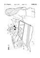
- FIG. 1Illustrated in FIG. 1 is an optical scanner 10 in accordance with an exemplary embodiment of the present invention for optically reading a bar code 12 suitably printed on a label secured to a multisided article or item 14.
- the item 14may have any suitable configuration, such as the six sided rectangular box illustrated, which is traversed or swiped in the direction S over the scanner 10 manually by a clerk 16.
- the housing 20includes a substantially horizontal first aperture or window 24 suitably disposed in the tray 22, and a second aperture or window 26 obliquely adjoining the first window 24, and extending generally vertically upwardly therefrom.
- the first and second windowsare made of a suitably transparent material and are configured for scanning the item 14 as it is swiped thereacross.
- the first window 24includes a front edge 24a adjacent the second window 26, an opposite back edge 24b adjacent the clerk 16 which defines the check side of the scanner 10, a third edge 24c over which the item 14 may be first traversed, and a laterally opposite fourth side 24d.
- the item 14includes a front side 14a which faces the second window 26, an opposite back or check side 14b which faces the clerk 16, a leading side 14c which first traverses the windows 24, 26 in the swiped direction S illustrated, an opposite trailing side 14d which follows the leading side 14c, a bottom side 14e which faces downwardly toward the first window 24, and an opposite top side 14f which faces upwardly away from the first window 24.
- the item 14is illustrated as being swiped from right to left in FIG. 1, it may also be swiped in the reverse direction from left to right which correspondingly redefines the leading and trailing sides of the item 14 relative to the movement of the item over the first window 24.
- the scanner 10is illustrated schematically in FIG. 2 operatively joined to a Point Of Sale (POS) terminal 28 which conventionally receives transaction data from the scanner 10 and completes a transaction by finding price data for the decoded bar code in a price-lookup data file contained therein.
- POSPoint Of Sale
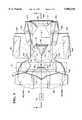
- the operative components of the scanner 10are disposed within the housing 20 and include a conventional laser 30 in the exemplary form of a laser diode for providing a suitable laser beam 32.
- the laser 30is illustrated in more particularity in FIGS. 3 and 4.
- a conventional optical transceiver 34includes an aperture for passing the laser beam 32 therethrough to a suitable rotary spinner 36.
- the spinner 36is illustrated in FIGS. 3 and 4 in optical alignment with the laser 30 and is in the form of a polygon.
- the spinner 36includes three circumferentially adjoining mirrored facets 36a,b,c for sequentially reflecting or scanning the laser beam 32 along an arcuate path to effect a scan beam 32s.
- a plurality of pattern mirrors designated generally by the prefix Mare suitably mounted in the housing 20 and optically aligned with the spinner 36 for reflecting the scan beam 32s through the first and second windows 24, 26 to effect for each revolution of the spinner 36 a collective plurality of individual and different scan lines illustrated in FIGS. 5 and 6 and identified by the numerical prefixes 1 through 8.
- the scan lines 1-8are arranged or grouped by respective ones of the pattern mirrors M in first and second patterns corresponding with the first and second windows 24, 26, respectively, as illustrated in FIGS. 6 and 5.
- one or more of the scan lines 32swill traverse the bars and spaces of the bar code 12 creating a scattered light return beam 32r which returns along the pattern mirrors M and spinner 36 to the optical transceiver 34 from which it is suitably reflected by a deflector or relay mirror 40 from which it is detected by a conventional photodetector 42 optically aligned therewith.
- the photodetector 42 as illustrated in FIG. 2is suitably electrically joined to a conventional control circuit 44 which is effective for decoding the return beam 32r from scanning the bar code 12.
- the decoded signalis suitably carried to the POS terminal 28 for use in a conventional manner such as for looking up the price of the item 14.
- the control circuit 44is suitably joined to the laser 30 and the motor 38 for controlling operation of the scanner 10 in a conventional manner.
- the three spinner facets 36a-care preferably flat mirrors extending about 120° each for collectively forming the perimeter of the spinner 36. Since only a finite number of the pattern mirrors M may be mounted in the limited volume within the housing 20, the spinner facets 36a-c are preferably disposed at different elevation angles E as illustrated in FIG. 4 for effecting three different sets of scan lines from the same pattern mirrors for increasing density of the first and second patterns.
- the three sets of scan linesare illustrated in FIGS. 5 and 6 by the suffix letters a,b,c associated with the scan lines 1-8.
- the corresponding three sets of scan linesare generally parallel to each other. In this way, more scan line coverage per area may be obtained from the same number of pattern mirrors M.
- the respective elevation angles E of the spinner facets 36a,b,care 81°, 78°, and 76.95°, respectively.
- the back side 14b of the item 14 illustrated in FIG. 2is swiped across the windows 24, 26 with the bottom side 14e facing downwardly toward the first window 24, and the front side extending vertically and facing toward the second window 26, and generally parallel thereto, for illuminating thereon the scan lines 1-8.
- the first pattern illustrated in FIG. 6includes ladder scan lines 2 and 7 which project vertically on the item 14 from the back side 14b thereof for reading a ladder orientation of the bar code 12 thereon. Also in the preferred embodiment illustrated in FIG.
- the first patternincludes a symmetrical set of the ladder scan lines 2 and 7 which project vertically on the item 14 along the back side 14b, as well as on the leading and trailing sides 14c,d thereof. In this way, back side scanning of the item 14 may now be obtained for increasing reliability of scanning of the item 14, while also increasing the effective orientation range of the item 14.
- the pattern mirrors Minclude a first triad set or sub-group of first, second, and third pattern mirrors designated M21, M22, and M23.
- the prefix Mdesignates the pattern mirrors generally.
- the first number of the suffixdesignates the sequence of the pattern mirrors relative to the rotating spinner 36 and the corresponding mirror set.
- the second number of the suffixdesignates the sequence of scan beam reflection from mirror-to-mirror in each pattern mirror set, with -1 being a primary mirror, -2 being a secondary mirror, etc.
- each setincluding a primary mirror, e.g. M11, M21, etc., and two or three secondary mirrors designated by the suffix 1, 2, 3.
- a primary mirrore.g. M11, M21, etc.
- two or three secondary mirrorsdesignated by the suffix 1, 2, 3.
- Table 1defines the several pattern mirrors and their orientation in space relative to an X, Y, Z coordinate system centered in the top of the first window 24 as illustrated in FIGS. 3 and 4.
- the X-axisrepresents the longitudinal centerline axis of the first window 24 and scanner 10, and is directed in an aft direction from the second window 26.
- the Y-axisextends vertically and perpendicularly upwardly from the first window 24.
- the Z-axisextends laterally in the horizontal plane of the first window 24 in the exemplary direction of swiping S.
- the X, Y, Z coordinates of each of the pattern mirrorsis listed in millimeters at the center of the respective mirror, and three conventional direction cosines COS (A), COS (B), and COS (C) identify orientation of the normal vectors of the plane of the pattern mirrors.
- the spinner 36rotates counterclockwise in this exemplary embodiment, with the laser beam 32 reflecting off each of the spinner facets 36a-c in turn to form the scan beam 32s which is reflected in turn from each of the pattern mirrors M11 through M81.
- the scan beam 32sis reflected from the first pattern mirror M11 in turn off the secondary pattern mirror M12 to form scan lines 1a,b,c from the respective spinner facets 36a,b,c.
- the first facet 36arotates counterclockwise, the scan beam 32s passes from the first primary mirror M11 to the second primary mirror M21, which in turn reflects the scan beam 32s off the secondary and tertiary mirrors M22 and M23 to form the second scan line 2a.
- the second and third spinner facets 36b,csimilarly generate the symmetrical scan lines 2b,c.
- the respective sets of pattern mirrors including primary pattern mirrors M11, M31, M41, M51, M61, and M81are conventional in configuration and orientation for producing the respective scan lines therefrom, except as further explained hereinbelow.
- the first triad set of pattern mirrors M21, M22, and M23provides in accordance with the present invention new back side scanning capability within the limited volume of the housing 20.
- These three triad mirrorsare optically aligned between the spinner 36 and the first window 24 as illustrated in FIGS. 3 and 4 for relaying or extending the first scan pattern to the back edge 24b of the first window 24 as illustrated in FIG. 6.
- the laser 30is colinearly aligned with the spinner 36 below the first window 24 along the longitudinal centerline X-axis for projecting the laser beam 32 from the front toward the back edges 24a,b of the first window 24.
- the window front edge 24ais disposed on the forward side of the spinner 36 with the back edge 24b being disposed aft of the spinner 36 in this configuration.
- Each of the spinner facets 36a-c illustrated in FIG. 3has an equal angular coverage or range R during rotation within which the laser beam 32 from the laser 30 is reflected as the scan beam 32s along the arcuate path traced by the rotating spinner 36.
- the annular coverage Ris conventionally determined by dividing 720° by the number of facets, with the three facets illustrated therefore each having an annular coverage R of 240°. As the number of facets increases the angular coverage R decreases and affects the scan budget and scan patterns.
- a pair of the triad sets of pattern mirrorsare preferably disposed symmetrically about the spinner 36 along the third and fourth edges 24c,d of the first window 24 for respectively scanning the laser beam 32 from the spinner 36 to effect a symmetrical set of the oblique ladder scan lines 2 and 7 adjacent to the back edge 24b of the first window 24.
- FIG. 3illustrates the first triad set of pattern mirrors M21, M22, M23 and the second set of triad mirrors M71, M72, and M73 shown symmetrically disposed on opposite sides of the centerline X-axis.
- the second primary mirror M21reflects the scan beam 32s from the spinner 36 at the upper left corner of the first window 24 illustrated in FIG. 3 on one side of the spinner 36 to the secondary mirror M22 at the lower right corner of the window on the opposite side of the spinner 36.
- the seventh primary mirror M71reflects the scan beam 32s from the spinner 36 at the lower left corner of the window 24 on one side of the spinner 36 to the secondary mirror M72 at the upper right corner of the window 24 on the opposite side of the spinner 36.
- the scan beam 32sis effectively relayed behind the spinner 36 for reaching the vicinity of the back edge 24b of the window 24 for being reflected upwardly through the first window 24 for reading the back side of the item 14. Since the respective secondary and tertiary mirrors M22, M23 and M72, M73 are disposed near corresponding opposite corners of the back edge of the window 24, the corresponding ladder scan lines 2a,b,c and 7a,b,c, not only project toward the item back side 14b but also along the item leading and trailing sides 14c,d, respectively, for reading the ladder bar code 12 placed thereon.
- the first triad mirror setis positioned in part, e.g., primary mirror M21, within the angular coverage R for first deflecting the scan beam 32s from the spinner 36.
- the first triad mirror M71 of the second setis symmetrically disposed on the opposite side of the spinner 36 within the angular coverage R.
- the corresponding second and third triad mirrors of the two setsi.e. M22, M23 and M72, M73, are disposed together at diametrically opposite back corners of the first window 24 for reflecting in turn the scan beam 32s from respective ones of the first triad mirrors M21 and M71 to project the scan beam vertically through the first window 24.
- the mirrors of the two triad sets as illustrated in FIG. 3are preferably optically aligned to effect an intersecting pair of the symmetrical oblique scan lines 2 and 7 through the first window 24 as illustrated in FIG. 6 so that each triad set is effective for reading the ladder bar code 12 on the item back side 14b, and on a different one of the leading and trailing sides 14c,d.
- the first triad setcan read a ladder bar code on the back and leading sides 14b,c of the item 14.
- the second triad setcan read a ladder bar code on the back and trailing sides 14b,d of the item 14.
- FIG. 6illustrates the two sets of ladder scan lines 2 and 7 intersecting each other generally along the centerline axis of the first window 24.
- the vertical projections of these oblique scan lines 2,7 on the item 14are effective for covering the leading, back, and trailing sides 14b,c,d of the item 14 in one swipe.
- the scanner 10is further configured for steering or intercepting a portion of the scan lines from the second window 26 to the first window 24, which are designated as steered scan lines 45b,c.
- the steered scan lineseffect picket scan lines 45b,c for reading a picket orientation of the bar code 12 on the back side of the item 14.
- first and second steering mirrors SM1 and SM2which are separately disposed symmetrically with the spinner 36 about the centerline X-axis as shown in FIGS. 3 and 4.
- the first and second steering mirrors SM1,2are preferably flat mirrors sized and positioned in optical alignment with the spinner 36 to intercept a suitable scan line portion from at least one of the spinner facets 36a-c.
- the first steering mirror SM1is a primary mirror optically aligned between the spinner 36 and a selected portion of the pattern mirrors within the angular coverage R for first intercepting the scan line portion in the pattern mirrors and from the second window 26.
- the second steering mirror SM2is a secondary mirror optically aligned with the first steering mirror SM1 on an opposite side of the spinner 36.
- the first steering mirror SM1is disposed forward of the spinner 36
- the second steering mirror SM2is disposed aft of the spinner 36, both symmetrically straddling the centerline X-axis symmetrically with the spinner 36.
- the pattern mirrorsinclude the common mirror M41/M51 which is disposed symmetrically with the spinner 36 about the centerline X-axis in the two symmetrical groups of pattern mirrors.
- the first steering mirror SM1is symmetrically laterally centered between the common mirror M41/M51 and the spinner 36 for intercepting the scan beam 32s from the spinner 36 over the center portion of the arcuate path, as illustrated in more particularity in FIG. 3.
- the first steering mirror SM1is optically aligned with at least one of the spinner facets 36a-c, and for example is optically aligned with only the second and third facets 36b,c as illustrated in FIG. 4.
- the first steering mirror SM1is preferably positioned out of optical alignment with at least one of the spinner facets such as the first facet 36a as also illustrated in FIG. 4. In this way, the first steering mirror SM1 intercepts a portion of the scan beam 32s along its arcuate travel as the spinner 36 rotates for the second and third facets 36b,c but not for the first facet 36a.
- the first steering mirror SM1is spaced vertically above the common mirror M41/M51 so that it intercepts the scan beam 32s from the spinner 36 for only the second and third facets 36b,c shown by the two phantom lines intersecting the first scan mirror SM1. Since the first spinner facet 36a has the maximum elevation angle E, the scan beam 32s is reflected below the first steering mirror SM1 to bypass this mirror and continue its normal path through the corresponding pattern mirrors.
- FIG. 5illustrates that the fourth and fifth scan lines 4b,c and 5b,c formed by the respective second and third spinner facets 36b,c have dotted line portions near the center of the second window 26 which have been removed by the first steering mirror SM1 and relayed through the second steering mirror SM2 to the first window 24 as the picket scan lines 45b,c.
Landscapes
- Physics & Mathematics (AREA)
- Electromagnetism (AREA)
- Engineering & Computer Science (AREA)
- General Physics & Mathematics (AREA)
- Health & Medical Sciences (AREA)
- General Health & Medical Sciences (AREA)
- Toxicology (AREA)
- Artificial Intelligence (AREA)
- Computer Vision & Pattern Recognition (AREA)
- Theoretical Computer Science (AREA)
- Optics & Photonics (AREA)
- Mechanical Optical Scanning Systems (AREA)
Abstract
Description
TABLE 1__________________________________________________________________________Mirror DefinitionCoordinates of the Center of Mirror Direction Cosines of the NormalMirror X Y Z COS(A) COS(B) COS(C) Scan Line__________________________________________________________________________M11 -10.6691 -63.4225 -112.9324 -0.0584 -0.5328 0.8442M12 -7.7222 -107.3025 -86.3600 0.0612 0.9981 0 1a,b,cM21 -58.8395 -73.0250 -64.9540 0.4518 -0.0858 0.8880M22 27.7535 -51.4470 63.4307 0.1917 -0.4397 -0.8774M23 78.4805 -55.7750 62.2500 -0.7442 0.6617 -0.0914 2a,b,cM31 -124.7245 -48.9998 -80.9834 0.1422 0.5736 0.8067M32 -157.747 61.4026 -69.2729 0.8243 -0.4695 0.3164 3a,b,cM41 -147.762 -43.4927 0 0.7372 0.6756 0M42 SAME AS M32 4a,b,cSM1 -107.6000 -59.8389 0 0.9832 -0.1822 0SM2 88.2551 -49.0432 0 -0.9135 0.4067 0 45b,cM51 SAME AS M41M52 -157.747 61.4026 69.2729 0.8243 -0.4695 -0.3164 5a,b,cM61 -124.7245 -48.9998 80.9834 0.1422 0.5736 -0.8067M62 SAME AS M52 6a,b,cM71 -58.8395 -73.0250 64.9540 0.4518 -0.0858 -0.8880M72 27.7535 -51.4470 -63.4307 0.1917 -0.4397 0.8774M73 78.4805 -55.7750 -62.2500 -0.7442 0.6617 0.0914 7a,b,cM81 -10.6691 -63.4225 112.9324 -0.0584 -0.5328 -0.8442M82 -7.7222 -107.3025 86.3600 0.0612 0.9981 0 8a,b,c__________________________________________________________________________
Claims (26)
Priority Applications (1)
| Application Number | Priority Date | Filing Date | Title |
|---|---|---|---|
| US08/764,345US5886336A (en) | 1996-12-12 | 1996-12-12 | Multiside coverage optical scanner |
Applications Claiming Priority (1)
| Application Number | Priority Date | Filing Date | Title |
|---|---|---|---|
| US08/764,345US5886336A (en) | 1996-12-12 | 1996-12-12 | Multiside coverage optical scanner |
Publications (1)
| Publication Number | Publication Date |
|---|---|
| US5886336Atrue US5886336A (en) | 1999-03-23 |
Family
ID=25070458
Family Applications (1)
| Application Number | Title | Priority Date | Filing Date |
|---|---|---|---|
| US08/764,345Expired - LifetimeUS5886336A (en) | 1996-12-12 | 1996-12-12 | Multiside coverage optical scanner |
Country Status (1)
| Country | Link |
|---|---|
| US (1) | US5886336A (en) |
Cited By (65)
| Publication number | Priority date | Publication date | Assignee | Title |
|---|---|---|---|---|
| US6076735A (en)* | 1997-04-24 | 2000-06-20 | Toshiba Tec Kabushiki Kaisha | Bar code scanning apparatus having a plurality of fixed mirrors which reflect scanning beams in orthogonal planes |
| US6176425B1 (en)* | 1998-09-10 | 2001-01-23 | Xerox Corporation | Information management system supporting multiple electronic tags |
| US6237852B1 (en)* | 1995-06-08 | 2001-05-29 | Psc Scanning, Inc. | Multiple plane weigh platter for multiple plane scanning systems |
| US6237851B1 (en)* | 1999-03-29 | 2001-05-29 | Ncr Corporation | Dual mode barcode scanner |
| US6286758B1 (en)* | 1999-02-17 | 2001-09-11 | Ncr Corporation | Reconfigurable checkout system |
| US6394345B1 (en) | 1999-11-02 | 2002-05-28 | Ncr Corporation | Checkout terminal and associated method having movable scanner |
| US6466389B1 (en)* | 1997-12-25 | 2002-10-15 | Fujitsu Limited | Library apparatus |
| US6466359B2 (en) | 2000-04-21 | 2002-10-15 | Fuji Photo Film Co., Ltd. | Multi-beam exposure apparatus |
| US6491224B2 (en)* | 1999-04-26 | 2002-12-10 | Fujitsu Limited | Optical scanning apparatus |
| US20030001010A1 (en)* | 2000-04-18 | 2003-01-02 | Mark Schmidt | Point-of-sale (POS) station having a based bar code driven cash register system with an integrated internet-enabled customer-kiosk terminal |
| US6502753B2 (en) | 2001-02-26 | 2003-01-07 | Ncr Corporation | Compact dual aperture scanner |
| US20030019933A1 (en)* | 1999-06-07 | 2003-01-30 | Metrologic Instruments, Inc. | Automated object identification and attribute acquisition system having a multi-compartment housing with optically-isolated light transmission apertures for operation of a planar laser illumination and imaging (PLIIM) based linear imaging subsystem and a laser-based object profiling subsystem integrated therein |
| US20030052173A1 (en)* | 2000-04-18 | 2003-03-20 | Adaptive Optics Associates, Inc. | Polygon-based bioptical POS scanning system employing dual independent optics platforms disposed beneath horizontal and vertical scanning windows |
| US6568598B1 (en) | 1992-07-14 | 2003-05-27 | Psc Scanning, Inc. | Multiple plane scanning system for data reading applications |
| US6588549B2 (en) | 2001-07-06 | 2003-07-08 | Ncr Corporation | Checkout system convertible between assisted and non-assisted configurations |
| US20030141367A1 (en)* | 2002-01-11 | 2003-07-31 | Metrologic Instruments, Inc. | Modular omnidirectional bar code symbol scanning system with at least one service port for removable installation of a scan module insert |
| US6629636B1 (en)* | 1999-12-20 | 2003-10-07 | Matsushita Electric Industrial Co., Ltd. | Sales transaction terminal device |
| US6631845B2 (en)* | 2001-04-03 | 2003-10-14 | Symbol Technologies, Inc. | Two window optical scanner |
| US6631844B1 (en)* | 1998-10-21 | 2003-10-14 | Fujitsu Limited | Optical scanner, code reader and bar code reader having increased degree of freedom in placement of optical parts |
| WO2003062956A3 (en)* | 2002-01-16 | 2003-10-16 | Metrologic Instr Inc | Point of sale (pos) based bar code reading and cash register systems with integrated internet-enabled customer-kiosk terminals |
| US20040046795A1 (en)* | 2002-03-08 | 2004-03-11 | Revelations In Design, Lp | Electric device control apparatus and methods for making and using same |
| US20040108383A1 (en)* | 2002-01-11 | 2004-06-10 | Timothy Good | Bioptical laser scanner for six-sided 360 pos-based scanning |
| US6758402B1 (en) | 1994-08-17 | 2004-07-06 | Metrologic Instruments, Inc. | Bioptical holographic laser scanning system |
| US20040189472A1 (en)* | 2002-02-01 | 2004-09-30 | Psc Scanning, Inc. | Combined data reader and electronic article surveillance (EAS) system |
| US6866197B1 (en)* | 2003-10-17 | 2005-03-15 | Ncr Corporation | Optical scanner having enhanced item side coverage |
| US20050098634A1 (en)* | 2000-04-18 | 2005-05-12 | Metrologic Instruments, Inc. | Bioptical laser scanning system providing 360° of omnidirectional bar code symbol scanning coverage at point of sale station |
| US20050109848A1 (en)* | 2002-01-11 | 2005-05-26 | Metrologic Instruments, Inc. | Bioptical laser scanning system providing 360° of omnidirectional bar code symbol scanning coverage at point of sale station |
| US6899272B2 (en)* | 2000-05-17 | 2005-05-31 | Symbol Technologies, Inc | Bioptics bar code reader |
| US20050145694A1 (en)* | 2002-02-01 | 2005-07-07 | Ncr Corporation | Checkout device including integrated barcode reader, scale, and EAS system |
| USD510090S1 (en)* | 2003-09-02 | 2005-09-27 | Ricoh Company, Ltd. | Bar code reader |
| US20050219053A1 (en)* | 2002-02-01 | 2005-10-06 | Psc Scanning, Inc. | Systems and methods for optical reading and EAS tag sensing and deactivating at retail checkout |
| US20060038009A1 (en)* | 2002-01-11 | 2006-02-23 | Metrologic Instruments, Inc. | Point of sale (POS) based bar code reading and cash register systems with integrated internet-enabled customer-kiosk terminals |
| US7051922B2 (en) | 1994-08-17 | 2006-05-30 | Metrologic Instruments, Inc. | Compact bioptical laser scanning system |
| EP1662291A1 (en)* | 2004-11-30 | 2006-05-31 | Ncr International Inc. | An optical scanner |
| US20060208894A1 (en)* | 2005-02-08 | 2006-09-21 | Friend Matthew J | Integrated data reader and electronic article surveillance (EAS) system |
| US20070119934A1 (en)* | 2005-11-30 | 2007-05-31 | Fujitsu Limited | Method and apparatus for optically reading identification information from commodity |
| US7272570B2 (en) | 1999-03-22 | 2007-09-18 | Ncr Corporation | System and methods for integrating a self-checkout system into an existing store system |
| US20080135619A1 (en)* | 2006-12-11 | 2008-06-12 | Sik Piu Kwan | Method, system, and apparatus for a multiple path image scanner |
| US20080249884A1 (en)* | 2000-11-24 | 2008-10-09 | Metrologic Instruments, Inc. | POS-centric digital imaging system |
| US20080277479A1 (en)* | 2003-11-13 | 2008-11-13 | Metrologic Instruments, Inc. | Countertop-based digital image capture and processing system having an illumination subsystem employing a single array of LEDS disposed behind an illumination focusing lens structure integrated within the imaging window, for generating a field of visible illumination highly confined below the field of view of the system operator and customers who are present during object illumination and imaging operations |
| USRE40576E1 (en) | 1997-10-14 | 2008-11-18 | Ncr Corporation | Point-of-sale system including isolation layer between client and server software |
| US20090127341A1 (en)* | 2007-11-19 | 2009-05-21 | Xiangyang Feng | Bar-code reading tool |
| US20090206161A1 (en)* | 2008-02-12 | 2009-08-20 | Datalogic Scanning, Inc. | Systems and methods for forming a composite image of multiple portions of an object from multiple perspectives |
| US20090286250A1 (en)* | 2006-05-19 | 2009-11-19 | James Arthur Hayward | Incorporating soluble security markers into cyanoacrylate solutions |
| US20100001863A1 (en)* | 2002-03-18 | 2010-01-07 | Salim Mohamed A | Operation monitoring and enhanced host communications in systems employing electronic article surveillance and rfid tags |
| EP1479054A4 (en)* | 2002-02-01 | 2010-05-12 | Datalogic Scanning Inc | Combined data reader and electronic article surveillance (eas) system |
| US20100138166A1 (en)* | 2008-12-03 | 2010-06-03 | International Business Machines Corporation | Estimating consumer alcohol intake using non-invasive technology |
| US20100163628A1 (en)* | 2008-02-12 | 2010-07-01 | Datalogic Scanning, Inc. | Two-plane optical code reader for acquisition of multiple views an object |
| US20100163626A1 (en)* | 2008-12-26 | 2010-07-01 | Datalogic Scanning, Inc. | Data reader having compact arrangement for acquisition of multiple views of an object |
| US20100163622A1 (en)* | 2008-02-12 | 2010-07-01 | Datalogic Scanning, Inc. | Monolithic mirror structure for use in a multi-perspective optical code reader |
| US20100163627A1 (en)* | 2008-12-26 | 2010-07-01 | Datalogic Scanning, Inc. | Image-based code reader for acquisition of multiple views of an object and methods for employing same |
| USD631478S1 (en)* | 2010-01-11 | 2011-01-25 | Datalogic Scanning, Inc. | Weigh platter or cover for a data reader |
| US20120085825A1 (en)* | 2010-10-07 | 2012-04-12 | Metrologic Instruments, Inc. | Laser scanning assembly having an improved scan angle-multiplication factor |
| US20120228381A1 (en)* | 2010-06-16 | 2012-09-13 | Symbol Technologies, Inc. | Optical scanner with customer interface |
| US8292181B1 (en)* | 2011-06-27 | 2012-10-23 | Ncr Corporation | Apparatus and system for a hybrid optical code scanner |
| US20130068840A1 (en)* | 2011-09-20 | 2013-03-21 | Metrologic Instruments, Inc. | Method of and apparatus for multiplying raster scanning lines by modulating a multi-cavity laser diode |
| US20130087617A1 (en)* | 2011-10-06 | 2013-04-11 | Symbol Technologies, Inc. | Apparatus for and method of reading targets arbitrarily oriented in imaging workstations |
| US8523076B2 (en) | 2012-01-10 | 2013-09-03 | Metrologic Instruments, Inc. | Omnidirectional laser scanning bar code symbol reader generating a laser scanning pattern with a highly non-uniform scan density with respect to line orientation |
| US8746569B2 (en) | 2008-02-12 | 2014-06-10 | Datalogic ADC, Inc. | Systems and methods for forming a composite image of multiple portions of an object from multiple perspectives |
| USD709888S1 (en)* | 2012-07-02 | 2014-07-29 | Symbol Technologies, Inc. | Bi-optic imaging scanner module |
| USD723560S1 (en)* | 2013-07-03 | 2015-03-03 | Hand Held Products, Inc. | Scanner |
| USD730901S1 (en)* | 2014-06-24 | 2015-06-02 | Hand Held Products, Inc. | In-counter barcode scanner |
| CN105095823A (en)* | 2015-09-14 | 2015-11-25 | 广东旭龙物联科技股份有限公司 | Imaging device of image-type barcode scanner, barcode reading method and barcode scanner |
| US9298962B1 (en)* | 2015-05-15 | 2016-03-29 | Symbol Technologies, Llc | Compact mirror arrangement for and method of capturing light and illuminating targets through a horizontal window of a point-of-transaction workstation |
| US9697406B2 (en) | 2015-05-15 | 2017-07-04 | Symbol Technologies, Llc | Compact mirror arrangement for and method of capturing light and illuminating targets through a horizontal window of a point-of-transaction workstation |
Citations (10)
| Publication number | Priority date | Publication date | Assignee | Title |
|---|---|---|---|---|
| US4097729A (en)* | 1975-05-27 | 1978-06-27 | Data General Corporation | Scanning system and method |
| US4652732A (en)* | 1985-09-17 | 1987-03-24 | National Semiconductor Corporation | Low-profile bar code scanner |
| US4713532A (en)* | 1985-11-21 | 1987-12-15 | Metrologic Instruments, Inc. | Compact omnidirectional laser scanner |
| US4861973A (en)* | 1987-06-18 | 1989-08-29 | Spectra-Physics, Inc. | Optical scan pattern generating arrangement for a laser scanner |
| US4960985A (en)* | 1985-11-21 | 1990-10-02 | Metrologic Instruments, Inc. | Compact omnidirectional laser scanner |
| US5028772A (en)* | 1988-08-26 | 1991-07-02 | Accu-Sort Systems, Inc. | Scanner to combine partial fragments of a complete code |
| US5132524A (en)* | 1990-05-21 | 1992-07-21 | Lazerdata Corporation | Multi directional laser scanner |
| US5206491A (en)* | 1990-03-02 | 1993-04-27 | Fujitsu Limited | Plural beam, plural window multi-direction bar code reading device |
| US5229588A (en)* | 1991-09-30 | 1993-07-20 | Ncr Corporation | Dual aperture optical scanner |
| US5684289A (en)* | 1995-10-30 | 1997-11-04 | Ncr Corporation | Optical scanner having enhanced item side coverage |
- 1996
- 1996-12-12USUS08/764,345patent/US5886336A/ennot_activeExpired - Lifetime
Patent Citations (10)
| Publication number | Priority date | Publication date | Assignee | Title |
|---|---|---|---|---|
| US4097729A (en)* | 1975-05-27 | 1978-06-27 | Data General Corporation | Scanning system and method |
| US4652732A (en)* | 1985-09-17 | 1987-03-24 | National Semiconductor Corporation | Low-profile bar code scanner |
| US4713532A (en)* | 1985-11-21 | 1987-12-15 | Metrologic Instruments, Inc. | Compact omnidirectional laser scanner |
| US4960985A (en)* | 1985-11-21 | 1990-10-02 | Metrologic Instruments, Inc. | Compact omnidirectional laser scanner |
| US4861973A (en)* | 1987-06-18 | 1989-08-29 | Spectra-Physics, Inc. | Optical scan pattern generating arrangement for a laser scanner |
| US5028772A (en)* | 1988-08-26 | 1991-07-02 | Accu-Sort Systems, Inc. | Scanner to combine partial fragments of a complete code |
| US5206491A (en)* | 1990-03-02 | 1993-04-27 | Fujitsu Limited | Plural beam, plural window multi-direction bar code reading device |
| US5132524A (en)* | 1990-05-21 | 1992-07-21 | Lazerdata Corporation | Multi directional laser scanner |
| US5229588A (en)* | 1991-09-30 | 1993-07-20 | Ncr Corporation | Dual aperture optical scanner |
| US5684289A (en)* | 1995-10-30 | 1997-11-04 | Ncr Corporation | Optical scanner having enhanced item side coverage |
Non-Patent Citations (1)
| Title |
|---|
| U.S. Patent application Ser. No. 08/550,150; filed Oct. 30, 1995.* |
Cited By (186)
| Publication number | Priority date | Publication date | Assignee | Title |
|---|---|---|---|---|
| US6974084B2 (en) | 1992-07-14 | 2005-12-13 | Psc Scanning, Inc. | Multiple plane scanning system for data reading applications |
| US20030201326A1 (en)* | 1992-07-14 | 2003-10-30 | Psc Scanning, Inc. | Multiple plane scanning system for data reading applications |
| US20090188980A1 (en)* | 1992-07-14 | 2009-07-30 | Datalogic Scanning, Inc | Multiple plane scanning system for data reading applications |
| US7198195B2 (en) | 1992-07-14 | 2007-04-03 | Psc Scanning, Inc. | Multiple plane scanning system for data reading applications |
| US20060249584A1 (en)* | 1992-07-14 | 2006-11-09 | Psc Scanning, Inc. | Multiple plane scanning system for data reading applications |
| US6568598B1 (en) | 1992-07-14 | 2003-05-27 | Psc Scanning, Inc. | Multiple plane scanning system for data reading applications |
| US20040217175A1 (en)* | 1992-07-14 | 2004-11-04 | Psc Scanning, Inc. | Multiple plane scanning system for data reading applications |
| US20060124745A1 (en)* | 1992-07-14 | 2006-06-15 | Psc Scanning, Inc. | Multiple plane scanning system for data reading applications |
| US7780087B2 (en) | 1992-07-14 | 2010-08-24 | Datalogic Scanning, Inc. | Multiple plane scanning system for data reading applications |
| US6991169B2 (en) | 1992-07-14 | 2006-01-31 | Psc Scanning, Inc. | Multiple plane scanning system for data reading applications |
| US7407103B2 (en) | 1994-08-17 | 2008-08-05 | Metrologic Instruments, Inc. | Bioptical holographic laser scanning system |
| US7051922B2 (en) | 1994-08-17 | 2006-05-30 | Metrologic Instruments, Inc. | Compact bioptical laser scanning system |
| US6991167B2 (en) | 1994-08-17 | 2006-01-31 | Metrologic Instruments, Inc. | Bioptical laser scanning system providing 360° of omnidirectional bar code symbol scanning coverage at a point of sale (POS) station |
| US20040134987A1 (en)* | 1994-08-17 | 2004-07-15 | Metrologic Instruments, Inc. | Bioptical laser scanning system providing 360 degrees of omnidirectional bar code symbol scanning coverage at a point of sale (POS) station |
| US6758402B1 (en) | 1994-08-17 | 2004-07-06 | Metrologic Instruments, Inc. | Bioptical holographic laser scanning system |
| USRE40071E1 (en) | 1995-06-08 | 2008-02-19 | Datalogic Scanning, Inc. | Multiple plane weigh platter for multiple plane scanning systems |
| US6237852B1 (en)* | 1995-06-08 | 2001-05-29 | Psc Scanning, Inc. | Multiple plane weigh platter for multiple plane scanning systems |
| US6076735A (en)* | 1997-04-24 | 2000-06-20 | Toshiba Tec Kabushiki Kaisha | Bar code scanning apparatus having a plurality of fixed mirrors which reflect scanning beams in orthogonal planes |
| USRE40576E1 (en) | 1997-10-14 | 2008-11-18 | Ncr Corporation | Point-of-sale system including isolation layer between client and server software |
| US6466389B1 (en)* | 1997-12-25 | 2002-10-15 | Fujitsu Limited | Library apparatus |
| US6176425B1 (en)* | 1998-09-10 | 2001-01-23 | Xerox Corporation | Information management system supporting multiple electronic tags |
| US6631844B1 (en)* | 1998-10-21 | 2003-10-14 | Fujitsu Limited | Optical scanner, code reader and bar code reader having increased degree of freedom in placement of optical parts |
| US6286758B1 (en)* | 1999-02-17 | 2001-09-11 | Ncr Corporation | Reconfigurable checkout system |
| US7272570B2 (en) | 1999-03-22 | 2007-09-18 | Ncr Corporation | System and methods for integrating a self-checkout system into an existing store system |
| US6237851B1 (en)* | 1999-03-29 | 2001-05-29 | Ncr Corporation | Dual mode barcode scanner |
| US6491224B2 (en)* | 1999-04-26 | 2002-12-10 | Fujitsu Limited | Optical scanning apparatus |
| US6840453B2 (en) | 1999-04-26 | 2005-01-11 | Fujitsu Limited | Optical scanning apparatus |
| US6988661B2 (en)* | 1999-06-07 | 2006-01-24 | Metrologic Instruments, Inc. | Automated object identification and attribute acquisition system having a multi-compartment housing with optically-isolated light transmission apertures for operation of a planar laser illumination and imaging (pliim) based linear imaging subsystem and a laser-base |
| US20030019933A1 (en)* | 1999-06-07 | 2003-01-30 | Metrologic Instruments, Inc. | Automated object identification and attribute acquisition system having a multi-compartment housing with optically-isolated light transmission apertures for operation of a planar laser illumination and imaging (PLIIM) based linear imaging subsystem and a laser-based object profiling subsystem integrated therein |
| US6394345B1 (en) | 1999-11-02 | 2002-05-28 | Ncr Corporation | Checkout terminal and associated method having movable scanner |
| US6629636B1 (en)* | 1999-12-20 | 2003-10-07 | Matsushita Electric Industrial Co., Ltd. | Sales transaction terminal device |
| US20030015588A1 (en)* | 2000-04-18 | 2003-01-23 | Metrologic Instruments, Inc. | Point-of-sale (POS) based bar code driven cash register system with an integrated internet-enabled customer-kiosk terminal |
| US6951304B2 (en) | 2000-04-18 | 2005-10-04 | Metrologic Instruments, Inc. | Polygon-based bioptical pos scanning system employing dual independent optics platforms disposed beneath horizontal and vertical scanning windows |
| US7341192B2 (en) | 2000-04-18 | 2008-03-11 | Metrologic Instruments, Inc. | Method of generating a complex laser scanning pattern from a bioptical laser scanning system for providing 360° of omnidirectional bar code symbol scanning coverage at a point of sale station |
| US20040016813A1 (en)* | 2000-04-18 | 2004-01-29 | Metrologic Instruments, Inc. | Bioptical laser scanning system providing 360 degree of omnidirectional bar code symbol scanning coverage at point of sale station |
| US6814292B2 (en) | 2000-04-18 | 2004-11-09 | Metrologic Instruments, Inc. | Bioptical laser scanning system providing 360° of omnidirectional bar code symbol scanning coverage at point of sale station |
| US20030052173A1 (en)* | 2000-04-18 | 2003-03-20 | Adaptive Optics Associates, Inc. | Polygon-based bioptical POS scanning system employing dual independent optics platforms disposed beneath horizontal and vertical scanning windows |
| US20030001010A1 (en)* | 2000-04-18 | 2003-01-02 | Mark Schmidt | Point-of-sale (POS) station having a based bar code driven cash register system with an integrated internet-enabled customer-kiosk terminal |
| US20050116031A1 (en)* | 2000-04-18 | 2005-06-02 | Metrologic Instruments, Inc. | Point of sale (POS) based bar code reading and cash register systems with integrated internet-enabled customer-kiosk terminals |
| US7841524B2 (en)* | 2000-04-18 | 2010-11-30 | Metrologic Instruments, Inc. | POS-based checkout system configured to enable the reading of code symbols on cashier and customer sides thereof, during a retail transaction being carried out at a point-of-sale (POS) station |
| US20030010825A1 (en)* | 2000-04-18 | 2003-01-16 | Mark Schmidt | Point of sale (POS) based bar code reading system with integrated internet-enabled customer-kiosk terminal |
| US20050098634A1 (en)* | 2000-04-18 | 2005-05-12 | Metrologic Instruments, Inc. | Bioptical laser scanning system providing 360° of omnidirectional bar code symbol scanning coverage at point of sale station |
| US20060255134A1 (en)* | 2000-04-18 | 2006-11-16 | Metrologic Instruments, Inc. | Point of sale (POS) based bar code reading and cash register systems with integrated internet-enabled customer-kiosk terminal |
| US20030102377A1 (en)* | 2000-04-18 | 2003-06-05 | Metrologic Instruments, Inc. | Polygon-based bioptical POS scanning system employing dual independent optics platforms disposed beneath horizontal and vertical scanning windows |
| US20050109847A1 (en)* | 2000-04-18 | 2005-05-26 | Metrologic Instruments, Inc. | Method of generating a complex laser scanning pattern from a bioptical laser scanning system for providing 360° of omnidirectional bar code symbol scanning coverage at a point of sale station |
| US7100832B2 (en) | 2000-04-18 | 2006-09-05 | Metrologic Instruments, Inc. | Bioptical laser scanning system providing 360° of omnidirectional bar code symbol scanning coverage at point of sale station |
| US6466359B2 (en) | 2000-04-21 | 2002-10-15 | Fuji Photo Film Co., Ltd. | Multi-beam exposure apparatus |
| US6899272B2 (en)* | 2000-05-17 | 2005-05-31 | Symbol Technologies, Inc | Bioptics bar code reader |
| US20080249884A1 (en)* | 2000-11-24 | 2008-10-09 | Metrologic Instruments, Inc. | POS-centric digital imaging system |
| US6502753B2 (en) | 2001-02-26 | 2003-01-07 | Ncr Corporation | Compact dual aperture scanner |
| US20040056099A1 (en)* | 2001-04-03 | 2004-03-25 | Symbol Technologies, Inc. | Two window optical scanner |
| US6631845B2 (en)* | 2001-04-03 | 2003-10-14 | Symbol Technologies, Inc. | Two window optical scanner |
| US6854655B2 (en) | 2001-04-03 | 2005-02-15 | Symbol Technologies, Inc. | Two window optical scanner |
| US6588549B2 (en) | 2001-07-06 | 2003-07-08 | Ncr Corporation | Checkout system convertible between assisted and non-assisted configurations |
| US7383996B2 (en) | 2002-01-11 | 2008-06-10 | Metrologic Instruments, Inc. | Bioptical laser scanner for six-sided 360° POS-based scanning |
| US7296748B2 (en) | 2002-01-11 | 2007-11-20 | Metrologic Instruments, Inc. | Bioptical laser scanning system providing 360° of omnidirectional bar code symbol scanning coverage at point of sale station |
| WO2003057396A3 (en)* | 2002-01-11 | 2003-11-06 | Metrologic Instr Inc | Bioptical laser scanner for six-sided 360° pos-based scanning |
| US7422156B2 (en) | 2002-01-11 | 2008-09-09 | Metrologic Instruments, Inc. | Bioptical laser scanning system for providing six-sided 360-degree omnidirectional bar code symbol scanning coverage at a point of sale station |
| US20030132291A1 (en)* | 2002-01-11 | 2003-07-17 | Metrologic Instruments, Inc. | Point of sale (POS) station having bar code reading system with integrated internet-enabled customer-kiosk terminal |
| US20060038009A1 (en)* | 2002-01-11 | 2006-02-23 | Metrologic Instruments, Inc. | Point of sale (POS) based bar code reading and cash register systems with integrated internet-enabled customer-kiosk terminals |
| US20040108383A1 (en)* | 2002-01-11 | 2004-06-10 | Timothy Good | Bioptical laser scanner for six-sided 360 pos-based scanning |
| US20030136843A1 (en)* | 2002-01-11 | 2003-07-24 | Metrologic Instruments, Inc. | Bar code symbol scanning system employing time-division multiplexed laser scanning and signal processing to avoid optical cross-talk and other unwanted light interference |
| US7753269B2 (en)* | 2002-01-11 | 2010-07-13 | Metrologic Instruments, Inc. | POS-based code driven retail transaction system configured to enable the reading of code symbols on cashier and customer sides thereof, during a retail transaction being carried out at a point-of-sale (POS) station, and driven by a retail transaction application program |
| US20050109848A1 (en)* | 2002-01-11 | 2005-05-26 | Metrologic Instruments, Inc. | Bioptical laser scanning system providing 360° of omnidirectional bar code symbol scanning coverage at point of sale station |
| US7083102B2 (en) | 2002-01-11 | 2006-08-01 | Metrologic Instruments, Inc. | Bioptical laser scanner for six-sided 360° Pos-based scanning |
| US7086597B2 (en) | 2002-01-11 | 2006-08-08 | Metrologic Instruments, Inc. | Bioptical laser scanning system providing 360 degree of omnidirectional bar code symbol scanning coverage at point of sale station |
| US20050109849A1 (en)* | 2002-01-11 | 2005-05-26 | Metrologic Instruments, Inc. | Method of generating a complex laser scanning pattern from a bioptical laser scanning system for providing 360° of omnidirectional bar code symbol scanning coverage at a point of sale station |
| US7740175B2 (en) | 2002-01-11 | 2010-06-22 | Metrologic Instruments, Inc. | Point-of-sale (POS) based laser scanning system providing six-sided 360 degree omni-directional bar code symbol scanning coverage at a POS station |
| US7374094B2 (en) | 2002-01-11 | 2008-05-20 | Metrologic Instruments, Inc. | Bioptical laser scanning system for providing six-sided omnidirectional bar code symbol scanning coverage at a point of sale station |
| US20050103852A1 (en)* | 2002-01-11 | 2005-05-19 | Metrologic Instruments, Inc. | Modular omnidirectional bar code symbol scanning system with at least one service port for removable installation of scan module insert |
| US7510118B2 (en) | 2002-01-11 | 2009-03-31 | Metrologic Instruments, Inc. | Bar code symbol scanning system employing time-division multiplexed laser scanning and signal processing to avoid optical cross-talk and other unwanted light interference |
| US20090121023A1 (en)* | 2002-01-11 | 2009-05-14 | Metrologic Instruments, Inc. | Point-of-sale (POS) based laser scanning system providing six-sided 360 degree omni-directional bar code symbol scanning coverage at a pos station |
| US20060283954A1 (en)* | 2002-01-11 | 2006-12-21 | Metrologic Instruments, Inc. | Bar code symbol scanning system employing time-division multiplexed laser scanning and signal processing to avoid optical cross-talk and other unwanted light interference |
| US20070007350A1 (en)* | 2002-01-11 | 2007-01-11 | Metrologic Instruments, Inc. | Bioptical laser scanning system for providing six-sided 360-degree omnidirectional bar code symbol scanning coverage at a point of sale station |
| US20070017995A1 (en)* | 2002-01-11 | 2007-01-25 | Metrologic Instruments, Inc. | Bioptical laser scanning system for providing six-sided omnidirectional bar code symbol scanning coverage at a point of sale station |
| US7314176B2 (en) | 2002-01-11 | 2008-01-01 | Metrologic Instruments, Inc. | Method of generating a complex laser scanning pattern from a bioptical laser scanning system for providing 360° of omnidirectional bar code symbol scanning coverage at a point of sale station |
| US20070290043A1 (en)* | 2002-01-11 | 2007-12-20 | Metrologic Instruments, Inc. | Point of sale (POS) based bar code reading and cash register systems with integrated internet-enabled customer-kiosk terminals |
| US20070029389A1 (en)* | 2002-01-11 | 2007-02-08 | Metrologic Instruments, Inc. | Bioptical laser scanner for six-sided 360º POS-based scanning |
| US20050061888A1 (en)* | 2002-01-11 | 2005-03-24 | Metrologic Instruments, Inc. | Bioptical laser scanning system providing 360 degree of omnidirectional bar code symbol scanning coverage at point of sale station |
| US7195167B2 (en) | 2002-01-11 | 2007-03-27 | Metrologic Instruments, Inc. | Modular omnidirectional bar code symbol scanning system with at least one service port for removable installation of scan module insert |
| US6874690B2 (en) | 2002-01-11 | 2005-04-05 | Metrologic Instruments, Inc. | Modular omnidirectional bar code symbol scanning system with at least one service port for removable installation of scan module insert |
| US6969004B2 (en) | 2002-01-11 | 2005-11-29 | Metrologic Instruments, Inc. | Bar code symbol scanning system employing time-division multiplexed laser scanning and signal processing to avoid optical cross-talk and other unwanted light interference |
| US20030141367A1 (en)* | 2002-01-11 | 2003-07-31 | Metrologic Instruments, Inc. | Modular omnidirectional bar code symbol scanning system with at least one service port for removable installation of a scan module insert |
| WO2003062956A3 (en)* | 2002-01-16 | 2003-10-16 | Metrologic Instr Inc | Point of sale (pos) based bar code reading and cash register systems with integrated internet-enabled customer-kiosk terminals |
| US20050099300A1 (en)* | 2002-02-01 | 2005-05-12 | Psc Scanning, Inc. | Combined data reader and electronic article surveillance (EAS) system |
| US7132947B2 (en) | 2002-02-01 | 2006-11-07 | Psc Scanning, Inc. | Systems and methods for data reading and EAS tag sensing and deactivating at retail checkout |
| US7172123B2 (en) | 2002-02-01 | 2007-02-06 | Psc Scanning, Inc. | Combined data reader and electronic article surveillance (EAS) system |
| US7170414B2 (en) | 2002-02-01 | 2007-01-30 | Psc Scanning, Inc. | Systems and methods for optical reading and EAS tag sensing and deactivating at retail checkout |
| EP1479054A4 (en)* | 2002-02-01 | 2010-05-12 | Datalogic Scanning Inc | Combined data reader and electronic article surveillance (eas) system |
| US20070210922A1 (en)* | 2002-02-01 | 2007-09-13 | Psc Scanning, Inc. | Systems and methods for data reading and EAS tag sensing and deactivating at retail checkout |
| US20040189472A1 (en)* | 2002-02-01 | 2004-09-30 | Psc Scanning, Inc. | Combined data reader and electronic article surveillance (EAS) system |
| US20070063045A1 (en)* | 2002-02-01 | 2007-03-22 | Psc Scanning, Inc. | Combined data reader and electronic article surveillance (EAS) system |
| US7374092B2 (en) | 2002-02-01 | 2008-05-20 | Datalogic Scanning, Inc. | Combined data reader and electronic article surveillance (EAS) system |
| US20050145694A1 (en)* | 2002-02-01 | 2005-07-07 | Ncr Corporation | Checkout device including integrated barcode reader, scale, and EAS system |
| US7495564B2 (en) | 2002-02-01 | 2009-02-24 | Datalogic Scanning, Inc. | Systems and methods for data reading and EAS tag sensing and deactivating at retail checkout |
| US8011579B2 (en)* | 2002-02-01 | 2011-09-06 | Datalogic Scanning, Inc. | Combined data reader and electronic article surveillance (EAS) system |
| US20050219053A1 (en)* | 2002-02-01 | 2005-10-06 | Psc Scanning, Inc. | Systems and methods for optical reading and EAS tag sensing and deactivating at retail checkout |
| US20040046795A1 (en)* | 2002-03-08 | 2004-03-11 | Revelations In Design, Lp | Electric device control apparatus and methods for making and using same |
| US20100001863A1 (en)* | 2002-03-18 | 2010-01-07 | Salim Mohamed A | Operation monitoring and enhanced host communications in systems employing electronic article surveillance and rfid tags |
| US8006904B2 (en) | 2002-03-18 | 2011-08-30 | Datalogic Scanning, Inc. | Operation monitoring and enhanced host communications in systems employing electronic article surveillance and RFID tags |
| EP1514141A4 (en)* | 2002-05-03 | 2008-01-23 | Metrologic Instr Inc | Modular omnidirectional bar code symbol scanning system with scan module insert |
| USD510090S1 (en)* | 2003-09-02 | 2005-09-27 | Ricoh Company, Ltd. | Bar code reader |
| US6866197B1 (en)* | 2003-10-17 | 2005-03-15 | Ncr Corporation | Optical scanner having enhanced item side coverage |
| EP1526475A3 (en)* | 2003-10-17 | 2005-11-16 | Ncr International Inc. | Optical scanner having enhanced item side coverage |
| US20080277476A1 (en)* | 2003-11-13 | 2008-11-13 | Anatoly Kotlarsky | Method of blocking a portion of illumination rays generated by a countertop-supported digital imaging system, and preventing illumination rays from striking the eyes of the system operator or nearby consumer during operation of said countertop-supported digital image capture and processing system installed at a retail point of sale (POS) station |
| US8132731B2 (en) | 2003-11-13 | 2012-03-13 | Metrologic Instruments, Inc. | Digital image capture and processing system having a printed circuit (PC) board with a light transmission aperture, wherein an image detection array is mounted on the rear side of said PC board, and a linear array of light emitting diodes (LEDS) is mounted on the front surface of said PC board, and aligned with an illumination-focusing lens structure integrated within said imaging window |
| US20080290172A1 (en)* | 2003-11-13 | 2008-11-27 | Metrologic Instruments, Inc. | Hand-supportable digital image capture and processing system employing manual trigger switching to control generation of a linear targeting illumination beam within the field of view (FOV), and to initiate illumination of the detected object and the capturing and processing of digital images thereof |
| US20080296384A1 (en)* | 2003-11-13 | 2008-12-04 | Anatoly Kotlarsky | Hand-supportable digital image capture and processing system having a printed circuit board with a light transmission aperture, through which the field of view (FOV) of the image detection array and visible targeting illumination beam are projected using a FOV-folding mirror |
| US20080314985A1 (en)* | 2003-11-13 | 2008-12-25 | Metrologic Instruments, Inc. | Digital image capture and processing system supporting advanced modes of automatic illumination and imaging control |
| US20090020610A1 (en)* | 2003-11-13 | 2009-01-22 | Metrologic Instruments, Inc. | Digital image capture and processing system employing an image formation and detection subsystem having an area-type image detection array supporting periodic occurrance of snap-shot type image acquisition cycles at a high-repetition rate during object illumination and imaging operations |
| US9104930B2 (en) | 2003-11-13 | 2015-08-11 | Metrologic Instruments, Inc. | Code symbol reading system |
| US20090057410A1 (en)* | 2003-11-13 | 2009-03-05 | Metrologic Instruments, Inc. | Digital image capture and processing system having a single printed circuit (PC) board with a light transmission aperture, wherein a first linear array of visible light emitting diodes (LEDS) are mounted on the rear side of the PC board for producing a linear targeting illumination beam, and wherein a second linear array of visible LEDS are mounted on the front side of said PC board for producing a field of visible illumination within the field of view (FOV) of the system |
| US20080283607A1 (en)* | 2003-11-13 | 2008-11-20 | Metrologic Instruments, Inc. | Hand-supportable digital image capture and processing system employing visible targeting illumination beam projected from an array of visible light sources on the rear surface of a printed circuit (PC) board having a light transmission aperture, and reflected off multiple folding mirrors and projected through the light transmission aperture into a central portion of the field of view of said system |
| US20080283606A1 (en)* | 2003-11-13 | 2008-11-20 | Anatoly Kotlarsky | Digital image capture and processing system supporting a periodic snapshot mode of operation wherein during each image acquistion cycle, the rows of image detection elements in the image detection array are exposed simultaneously to illumination |
| US20080290173A1 (en)* | 2003-11-13 | 2008-11-27 | Metrologic Instruments, Inc. | Hand-supportable digital image capture and processing system employing automatic object presence detection to control automatic generation of a linear targeting illumination beam within the field of view (FOV), and manual trigger switching to initiate illumination of the detected object and capturing and processing of digital images thereof |
| US8317105B2 (en) | 2003-11-13 | 2012-11-27 | Metrologic Instruments, Inc. | Optical scanning system having an extended programming mode and method of unlocking restricted extended classes of features and functionalities embodied therewithin |
| US8157174B2 (en) | 2003-11-13 | 2012-04-17 | Metrologic Instruments, Inc. | Digital image capture and processing system employing an image formation and detection system having an area-type image detection array supporting single snap-shot and periodic snap-shot modes of image acquisition during object illumination and imaging operations |
| US7997489B2 (en) | 2003-11-13 | 2011-08-16 | Metrologic Instruments, Inc. | Countertop-based digital image capture and processing system having an illumination subsystem employing a single array of LEDs disposed behind an illumination focusing lens structure integrated within the imaging window, for generating a field of visible illumination highly confined below the field |
| US8157175B2 (en) | 2003-11-13 | 2012-04-17 | Metrologic Instruments, Inc. | Digital image capture and processing system supporting a presentation mode of system operation which employs a combination of video and snapshot modes of image detection array operation during a single cycle of system operation |
| US20080277479A1 (en)* | 2003-11-13 | 2008-11-13 | Metrologic Instruments, Inc. | Countertop-based digital image capture and processing system having an illumination subsystem employing a single array of LEDS disposed behind an illumination focusing lens structure integrated within the imaging window, for generating a field of visible illumination highly confined below the field of view of the system operator and customers who are present during object illumination and imaging operations |
| US7967209B2 (en) | 2003-11-13 | 2011-06-28 | Metrologic Instruments, Inc. | Method of blocking a portion of illumination rays generated by a countertop-supported digital imaging system, and preventing illumination rays from striking the eyes of the system operator or nearby consumers during operation of said countertop-supported digital image capture and processing system installed at a retail point of sale (POS) station |
| US7980471B2 (en) | 2003-11-13 | 2011-07-19 | Metrologic Instruments, Inc. | Method of unlocking restricted extended classes of features and functionalities embodied within a digital image capture and processing system by reading feature/functionality-unlocking type code symbols |
| US7988053B2 (en) | 2003-11-13 | 2011-08-02 | Metrologic Instruments, Inc. | Digital image capture and processing system employing an image formation and detection subsystem having image formation optics providing a field of view (FOV) on an area-type image detection array, and a multi-mode illumination subsystem having near and far field LED-based illumination arrays for illuminating near and far field portions of said FOV |
| US8011585B2 (en) | 2003-11-13 | 2011-09-06 | Metrologic Instruments, Inc. | Digital image capture and processing system employing a linear LED-based illumination array mounted behind an illumination-focusing lens component integrated within the imaging window of the system |
| US8100331B2 (en) | 2003-11-13 | 2012-01-24 | Metrologic Instruments, Inc. | Digital image capture and processing system having a printed circuit (PC) board with light transmission aperture, wherein first and second field of view (FOV) folding mirrors project the FOV of a digital image detection array on the rear surface of said PC board, through said light transmission aperture |
| US8087588B2 (en) | 2003-11-13 | 2012-01-03 | Metrologic Instruments, Inc. | Digital image capture and processing system having a single printed circuit (PC) board with a light transmission aperture, wherein a first linear array of visible light emitting diodes (LEDs) are mounted on the rear side of the PC board for producing a linear targeting illumination beam, and wherein a second linear array of visible LEDs are mounted on the front side of said PC board for producing a field of visible illumination within the field of view (FOV) of the system |
| US8052057B2 (en) | 2003-11-13 | 2011-11-08 | Metrologic Instruments, Inc. | Method of programming the system configuration parameters of a digital image capture and processing system during the implementation of its communication interface with a host system without reading programming-type bar code symbols |
| US8047438B2 (en) | 2003-11-13 | 2011-11-01 | Metrologic Instruments, Inc. | Digital image capture and processing system employing an image formation and detection subsystem having an area-type image detection array supporting periodic occurrance of snap-shot type image acquisition cycles at a high-repetition rate during object illumination |
| US7922089B2 (en) | 2003-11-13 | 2011-04-12 | Metrologic Instruments, Inc. | Hand-supportable digital image capture and processing system employing automatic object presence detection to control automatic generation of a linear targeting illumination beam within the field of view (FOV), and manual trigger switching to initiate illumination |
| US7900839B2 (en) | 2003-11-13 | 2011-03-08 | Metrologic Instruments, Inc. | Hand-supportable digital image capture and processing system having a printed circuit board with a light transmission aperture, through which the field of view (FOV) of the image detection array and visible targeting illumination beam are projected using a FOV-folding mirror |
| US20080277473A1 (en)* | 2003-11-13 | 2008-11-13 | Metrologic Intruments, Inc. | Digital image capture and processing system employing an image formation and detection system having an area-type image detection array supporting single snap-shot and periodic snap-shot modes of image acquisition during object illumination and imaging operations |
| US7841533B2 (en) | 2003-11-13 | 2010-11-30 | Metrologic Instruments, Inc. | Method of capturing and processing digital images of an object within the field of view (FOV) of a hand-supportable digitial image capture and processing system |
| US7845561B2 (en) | 2003-11-13 | 2010-12-07 | Metrologic Instruments, Inc. | Digital image capture and processing system supporting a periodic snapshot mode of operation wherein during each image acquisition cycle, the rows of image detection elements in the image detection array are exposed simultaneously to illumination |
| US7845559B2 (en) | 2003-11-13 | 2010-12-07 | Metrologic Instruments, Inc. | Hand-supportable digital image capture and processing system employing visible targeting illumination beam projected from an array of visible light sources on the rear surface of a printed circuit (PC) board having a light transmission aperture, and reflected off multiple folding mirrors and projected through the light transmission aperture into a central portion of the field of view of said system |
| US20080277475A1 (en)* | 2003-11-13 | 2008-11-13 | Metrologic Instruments, Inc. | Digital image capture and processing system supporting a presentation mode of system operation which employs a combination of video and snapshot modes of image detection array operation during a single cycle of system operation |
| EP1662291A1 (en)* | 2004-11-30 | 2006-05-31 | Ncr International Inc. | An optical scanner |
| US20060113394A1 (en)* | 2004-11-30 | 2006-06-01 | Ncr Corporation | Optical scanner |
| US7137560B2 (en) | 2004-11-30 | 2006-11-21 | Ncr Corporation | Optical scanner |
| US8358211B2 (en) | 2005-02-08 | 2013-01-22 | Datalogic ADC, Inc. | Integrated data reader and electronic article surveillance (EAS) system |
| US20060208894A1 (en)* | 2005-02-08 | 2006-09-21 | Friend Matthew J | Integrated data reader and electronic article surveillance (EAS) system |
| US20100148967A1 (en)* | 2005-02-08 | 2010-06-17 | Datalogic Scanning, Inc. | Integrated data reader and electronic article surveillance (eas) system |
| US7619527B2 (en) | 2005-02-08 | 2009-11-17 | Datalogic Scanning, Inc. | Integrated data reader and electronic article surveillance (EAS) system |
| US20070119934A1 (en)* | 2005-11-30 | 2007-05-31 | Fujitsu Limited | Method and apparatus for optically reading identification information from commodity |
| EP1793327A1 (en)* | 2005-11-30 | 2007-06-06 | Fujitsu Limited | Method and apparatus for optically reading identification information from commodity |
| US20090286250A1 (en)* | 2006-05-19 | 2009-11-19 | James Arthur Hayward | Incorporating soluble security markers into cyanoacrylate solutions |
| US9087248B2 (en)* | 2006-12-11 | 2015-07-21 | Ncr Corporation | Method, system, and apparatus for a multiple path image scanner |
| US20080135619A1 (en)* | 2006-12-11 | 2008-06-12 | Sik Piu Kwan | Method, system, and apparatus for a multiple path image scanner |
| US20090127341A1 (en)* | 2007-11-19 | 2009-05-21 | Xiangyang Feng | Bar-code reading tool |
| US20090206161A1 (en)* | 2008-02-12 | 2009-08-20 | Datalogic Scanning, Inc. | Systems and methods for forming a composite image of multiple portions of an object from multiple perspectives |
| US20100163628A1 (en)* | 2008-02-12 | 2010-07-01 | Datalogic Scanning, Inc. | Two-plane optical code reader for acquisition of multiple views an object |
| US8608076B2 (en) | 2008-02-12 | 2013-12-17 | Datalogic ADC, Inc. | Monolithic mirror structure for use in a multi-perspective optical code reader |
| US20100163622A1 (en)* | 2008-02-12 | 2010-07-01 | Datalogic Scanning, Inc. | Monolithic mirror structure for use in a multi-perspective optical code reader |
| US8746569B2 (en) | 2008-02-12 | 2014-06-10 | Datalogic ADC, Inc. | Systems and methods for forming a composite image of multiple portions of an object from multiple perspectives |
| US8353457B2 (en) | 2008-02-12 | 2013-01-15 | Datalogic ADC, Inc. | Systems and methods for forming a composite image of multiple portions of an object from multiple perspectives |
| US8678287B2 (en) | 2008-02-12 | 2014-03-25 | Datalogic ADC, Inc. | Two-plane optical code reader for acquisition of multiple views of an object |
| US20100138166A1 (en)* | 2008-12-03 | 2010-06-03 | International Business Machines Corporation | Estimating consumer alcohol intake using non-invasive technology |
| US8195406B2 (en)* | 2008-12-03 | 2012-06-05 | International Business Machines Corporation | Estimating consumer status using non-invasive technology |
| US20100163626A1 (en)* | 2008-12-26 | 2010-07-01 | Datalogic Scanning, Inc. | Data reader having compact arrangement for acquisition of multiple views of an object |
| US8608077B2 (en) | 2008-12-26 | 2013-12-17 | Datalogic ADC, Inc. | Image-based code reader for acquisition of multiple views of an object and methods for employing same |
| US8322621B2 (en) | 2008-12-26 | 2012-12-04 | Datalogic ADC, Inc. | Image-based code reader for acquisition of multiple views of an object and methods for employing same |
| US8261990B2 (en)* | 2008-12-26 | 2012-09-11 | Datalogic ADC, Inc. | Data reader having compact arrangement for acquisition of multiple views of an object |
| US20100163627A1 (en)* | 2008-12-26 | 2010-07-01 | Datalogic Scanning, Inc. | Image-based code reader for acquisition of multiple views of an object and methods for employing same |
| USD659142S1 (en) | 2010-01-11 | 2012-05-08 | Datalogic ADC, Inc. | Weigh platter or cover for a data reader |
| USD631478S1 (en)* | 2010-01-11 | 2011-01-25 | Datalogic Scanning, Inc. | Weigh platter or cover for a data reader |
| USD642178S1 (en)* | 2010-01-11 | 2011-07-26 | Datalogic Scanning, Inc. | Weigh platter or cover for a data reader |
| USD676446S1 (en) | 2010-01-11 | 2013-02-19 | Datalogic ADC, Inc. | Weigh platter or cover for a data reader |
| US8613393B2 (en)* | 2010-06-16 | 2013-12-24 | Symbol Technologies, Inc. | Optical scanner with customer interface |
| US20120228381A1 (en)* | 2010-06-16 | 2012-09-13 | Symbol Technologies, Inc. | Optical scanner with customer interface |
| US8408469B2 (en)* | 2010-10-07 | 2013-04-02 | Metrologic Instruments, Inc. | Laser scanning assembly having an improved scan angle-multiplication factor |
| US20120085825A1 (en)* | 2010-10-07 | 2012-04-12 | Metrologic Instruments, Inc. | Laser scanning assembly having an improved scan angle-multiplication factor |
| US8292181B1 (en)* | 2011-06-27 | 2012-10-23 | Ncr Corporation | Apparatus and system for a hybrid optical code scanner |
| US20130068840A1 (en)* | 2011-09-20 | 2013-03-21 | Metrologic Instruments, Inc. | Method of and apparatus for multiplying raster scanning lines by modulating a multi-cavity laser diode |
| US8678285B2 (en)* | 2011-09-20 | 2014-03-25 | Metrologic Instruments, Inc. | Method of and apparatus for multiplying raster scanning lines by modulating a multi-cavity laser diode |
| US8740075B2 (en)* | 2011-10-06 | 2014-06-03 | Symbol Technologies, Inc. | Apparatus for and method of reading targets arbitrarily oriented in imaging workstations |
| US20130087617A1 (en)* | 2011-10-06 | 2013-04-11 | Symbol Technologies, Inc. | Apparatus for and method of reading targets arbitrarily oriented in imaging workstations |
| US8523076B2 (en) | 2012-01-10 | 2013-09-03 | Metrologic Instruments, Inc. | Omnidirectional laser scanning bar code symbol reader generating a laser scanning pattern with a highly non-uniform scan density with respect to line orientation |
| USD709888S1 (en)* | 2012-07-02 | 2014-07-29 | Symbol Technologies, Inc. | Bi-optic imaging scanner module |
| USD723560S1 (en)* | 2013-07-03 | 2015-03-03 | Hand Held Products, Inc. | Scanner |
| USD766244S1 (en) | 2013-07-03 | 2016-09-13 | Hand Held Products, Inc. | Scanner |
| USD826233S1 (en) | 2013-07-03 | 2018-08-21 | Hand Held Products, Inc. | Scanner |
| USD730901S1 (en)* | 2014-06-24 | 2015-06-02 | Hand Held Products, Inc. | In-counter barcode scanner |
| USD757009S1 (en) | 2014-06-24 | 2016-05-24 | Hand Held Products, Inc. | In-counter barcode scanner |
| US9298962B1 (en)* | 2015-05-15 | 2016-03-29 | Symbol Technologies, Llc | Compact mirror arrangement for and method of capturing light and illuminating targets through a horizontal window of a point-of-transaction workstation |
| US9697406B2 (en) | 2015-05-15 | 2017-07-04 | Symbol Technologies, Llc | Compact mirror arrangement for and method of capturing light and illuminating targets through a horizontal window of a point-of-transaction workstation |
| US10025962B2 (en) | 2015-05-15 | 2018-07-17 | Symbol Technologies, Llc | Devices and methods for imaging targets |
| CN105095823A (en)* | 2015-09-14 | 2015-11-25 | 广东旭龙物联科技股份有限公司 | Imaging device of image-type barcode scanner, barcode reading method and barcode scanner |
Similar Documents
| Publication | Publication Date | Title |
|---|---|---|
| US5886336A (en) | Multiside coverage optical scanner | |
| US5801370A (en) | Multi-directional bar code reading device | |
| US6059189A (en) | Dual aperture optical scanner | |
| US7780087B2 (en) | Multiple plane scanning system for data reading applications | |
| US4647143A (en) | Light-beam scanning apparatus | |
| USRE42651E1 (en) | Optical scanner having enhanced item side coverage | |
| KR940010808B1 (en) | Laser scanner for bar code reader | |
| US6045046A (en) | Full coverage barcode scanner | |
| US3988573A (en) | Three line scanner for bar code symbols | |
| EP0151915B1 (en) | Optical scanner with beam directing holograms at window | |
| US5175421A (en) | Dual depth of field deflector for bar code scanners | |
| US5498862A (en) | Side scanning bar code reader with vertical and horizontal scan patterns | |
| US5198649A (en) | Bar code scanner and method of scanning bar codes labels with or without an Add-On code | |
| US5892214A (en) | Low profile planar scanner | |
| EP0042946A2 (en) | Holographic scanner for generating scan patterns and its application to the sensing of bar code labels | |
| JPH0823629B2 (en) | Optical reader | |
| US6543694B1 (en) | Extended coverage barcode scanner | |
| US6237851B1 (en) | Dual mode barcode scanner | |
| JPH06150039A (en) | Barcode reader | |
| JPH08335243A (en) | Barcode scanner | |
| US5610385A (en) | Optical bar code scanner which produces substantially perpendicular scan lines | |
| JP2576604B2 (en) | Laser light scanning device | |
| US7077326B2 (en) | Generating a scan pattern over multiple surfaces of symbol-bearing objects passing through flat bed reader | |
| JPH0511288B2 (en) | ||
| JPS5986024A (en) | Hologram scanner |
Legal Events
| Date | Code | Title | Description |
|---|---|---|---|
| AS | Assignment | Owner name:NCR CORPORATION, OHIO Free format text:ASSIGNMENT OF ASSIGNORS INTEREST;ASSIGNORS:TANG, HONG;MERGENTHALER, BARRY;DETWILER, PAUL O.;AND OTHERS;REEL/FRAME:008353/0310 Effective date:19961209 | |
| STCF | Information on status: patent grant | Free format text:PATENTED CASE | |
| FPAY | Fee payment | Year of fee payment:4 | |
| FPAY | Fee payment | Year of fee payment:8 | |
| FPAY | Fee payment | Year of fee payment:12 | |
| AS | Assignment | Owner name:JPMORGAN CHASE BANK, N.A., AS ADMINISTRATIVE AGENT, ILLINOIS Free format text:SECURITY AGREEMENT;ASSIGNORS:NCR CORPORATION;NCR INTERNATIONAL, INC.;REEL/FRAME:032034/0010 Effective date:20140106 Owner name:JPMORGAN CHASE BANK, N.A., AS ADMINISTRATIVE AGENT Free format text:SECURITY AGREEMENT;ASSIGNORS:NCR CORPORATION;NCR INTERNATIONAL, INC.;REEL/FRAME:032034/0010 Effective date:20140106 | |
| AS | Assignment | Owner name:JPMORGAN CHASE BANK, N.A., ILLINOIS Free format text:SECURITY AGREEMENT;ASSIGNORS:NCR CORPORATION;NCR INTERNATIONAL, INC.;REEL/FRAME:038646/0001 Effective date:20160331 | |
| AS | Assignment | Owner name:NCR VOYIX CORPORATION, GEORGIA Free format text:RELEASE OF PATENT SECURITY INTEREST;ASSIGNOR:JPMORGAN CHASE BANK, N.A., AS ADMINISTRATIVE AGENT;REEL/FRAME:065346/0531 Effective date:20231016 |